EP4141727A1 - Modeling new designs for electromagnetic effects - Google Patents
Modeling new designs for electromagnetic effects Download PDFInfo
- Publication number
- EP4141727A1 EP4141727A1 EP22177764.2A EP22177764A EP4141727A1 EP 4141727 A1 EP4141727 A1 EP 4141727A1 EP 22177764 A EP22177764 A EP 22177764A EP 4141727 A1 EP4141727 A1 EP 4141727A1
- Authority
- EP
- European Patent Office
- Prior art keywords
- design
- model
- tool
- new design
- interest
- Prior art date
- Legal status (The legal status is an assumption and is not a legal conclusion. Google has not performed a legal analysis and makes no representation as to the accuracy of the status listed.)
- Pending
Links
Images




Classifications
-
- G—PHYSICS
- G06—COMPUTING OR CALCULATING; COUNTING
- G06F—ELECTRIC DIGITAL DATA PROCESSING
- G06F30/00—Computer-aided design [CAD]
- G06F30/20—Design optimisation, verification or simulation
- G06F30/23—Design optimisation, verification or simulation using finite element methods [FEM] or finite difference methods [FDM]
-
- G—PHYSICS
- G06—COMPUTING OR CALCULATING; COUNTING
- G06F—ELECTRIC DIGITAL DATA PROCESSING
- G06F30/00—Computer-aided design [CAD]
- G06F30/10—Geometric CAD
- G06F30/15—Vehicle, aircraft or watercraft design
-
- G—PHYSICS
- G06—COMPUTING OR CALCULATING; COUNTING
- G06F—ELECTRIC DIGITAL DATA PROCESSING
- G06F30/00—Computer-aided design [CAD]
- G06F30/20—Design optimisation, verification or simulation
- G06F30/27—Design optimisation, verification or simulation using machine learning, e.g. artificial intelligence, neural networks, support vector machines [SVM] or training a model
-
- G—PHYSICS
- G06—COMPUTING OR CALCULATING; COUNTING
- G06F—ELECTRIC DIGITAL DATA PROCESSING
- G06F2111/00—Details relating to CAD techniques
- G06F2111/10—Numerical modelling
-
- G—PHYSICS
- G06—COMPUTING OR CALCULATING; COUNTING
- G06F—ELECTRIC DIGITAL DATA PROCESSING
- G06F2119/00—Details relating to the type or aim of the analysis or the optimisation
- G06F2119/06—Power analysis or power optimisation
Definitions
- the disclosure relates to design modeling in general, and in particular, to modeling new designs for electromagnetic effects.
- Multidisciplinary analysis and optimization is used to study a variety of airplane architectures and design decisions. Many disciplines are incorporated into the optimization, except electromagnetic effects considerations and coupling of the electromagnetic effects to structural performance considerations. At present, the electromagnetic effects analysis takes a considerable amount of time and so lags behind the structural analysis. Accordingly, those skilled in the art continue with research and development efforts in the field of modeling designs for electromagnetic effects.
- a method for modeling a new design for electromagnetic effects includes identifying, with a model based system engineering tool executed in a computer, an area of interest in the new design where a lightning strike may occur.
- the new design includes a plurality of structural features and a plurality of electromagnetic features.
- the method further includes generating, with an electromagnetic effects solver tool and a structural solver tool, a design model for the area of interest in the new design, extracting a plurality of design parameters from the design model, and generating a reduced order model by processing the plurality of design parameters, one or more of a plurality of test results, and one or more of a plurality of simulation results with a modeling tool.
- the reduced order model couples the plurality of structural features with the plurality of electromagnetic features.
- the plurality of test results is determined by tests of a plurality of known designs that are similar to the new design.
- the plurality of simulation results is determined by simulations of a plurality of known models that are similar to the new design.
- the method further includes storing the reduced order model in a storage medium that is readable by a statistical modeling tool.
- the reduced order model includes one or more of an algebraic model, an ordinary differential equation model, and a partial differential equation model compatible with the statistical modeling tool.
- the electromagnetic effects solver tool and the structural solver tool are each a numerical modeling tool.
- the statistical modeling tool is a multidisciplinary analysis and optimization tool.
- the plurality of design parameters includes a peak power density in the area of interest due to the lightning strike, a peak electrical current in the area of interest due to the lightning strike, and a peak temperature in the area of interest due to the lightning strike.
- the plurality of design parameters includes one or more fatigue margins in the area of interest, one or more stress margins in the area of interest, and one or more damage limits in the area of interest.
- the generating of the design model includes predicting a power density at an edge of the new design due to the lightning strike based on the plurality of design parameters, predicting a damage to the new design due to the lightning strike based on the plurality of design parameters, and predicting an ignition hazard that originates from the new design due to the lightning strike based on the plurality of design parameters.
- the method includes increasing one or more weights of the plurality of simulation results where the plurality of known models corresponds to the plurality of test results.
- the new design forms a portion of an apparatus.
- the apparatus is an aircraft.
- a method for modeling a new design for electromagnetic effects includes storing, in a memory circuit, a plurality of test results that is determined by tests of a plurality of known designs that are similar to the new design.
- the new design includes a plurality of structural features and a plurality of electromagnetic features.
- the method further includes storing a plurality of simulation results that is determined by simulations of a plurality of known models that are similar to the new design, extracting a plurality of design parameters from a design model of the new design in an area of interest where a lightning strike may occur, generating a reduced order model by processing the plurality of design parameters, one or more of the plurality of test results, and one or more of the plurality of simulation results with a modeling tool, wherein the reduced order model couples the plurality of structural features with the plurality of electromagnetic features, and storing the reduced order model in a storage medium suitable for use by a statistical modeling tool.
- the reduced order model includes one or more of an algebraic model, an ordinary differential equation model, and a partial differential equation model compatible with the statistical modeling tool.
- the statistical modeling tool is a multidisciplinary analysis and optimization tool.
- the method includes parsing the plurality of test results and the plurality of simulation results among a plurality of training results, a plurality of validation results, and a plurality of testing data.
- the method includes generating a map of a parameter space populated by the plurality of test results and the plurality of simulation results.
- the new design forms a portion of an aircraft.
- the method includes identifying, with a model based system engineering tool executed in a computer, the area of interest in the new design where the lightning strike may occur, and generating, with an electromagnetic effects solver tool and a structural solver tool, the design model for the area of interest in the new design.
- a system includes a memory circuit and a processor.
- the memory circuit is configured to store a plurality of test results and a plurality of simulation results.
- the plurality of test results is determined by testing a plurality of known designs that are similar to a new design.
- the plurality of simulation results is determined by simulating a plurality of known models that are similar to the new design.
- the new design includes a plurality of structural features and a plurality of electromagnetic features.
- the processor is configured to identify an area of interest in the new design where a lightning strike may occur, generate a design model for the area of interest in the new design with an electromagnetic effects solver tool and a structural solver tool, extract a plurality of design parameters from the design model, and generate a reduced order model by processing the plurality of design parameters, one or more of the plurality of test results, and one or more of the plurality of simulation results with a modeling tool.
- the reduced order model couples the plurality of structural features with the plurality of electromagnetic features.
- the processor is further configured to store the reduced order model in a storage medium that is readable by a statistical modeling tool.
- the reduced order model includes one or more of an algebraic model, an ordinary differential equation model, and a partial differential equation model compatible with the statistical modeling tool, and the statistical modeling tool is a multidisciplinary analysis and optimization tool.
- the new design forms a portion of an aircraft.
- Examples of the disclosure generally provide a technique for modeling new designs for electromagnetic effects.
- Finite element modeling capabilities for the electromagnetic effects and structures are coupled and integrated into a model based engineering architecture.
- a wide database of known models and supplemental test data is accessible in the model based engineering architecture and may be used to extract key parameters into a database.
- the database subsequently feeds a modeling tool to create a reduced order model.
- the reduced order model is used by a multidisciplinary analysis and optimization technique to take into account the electromagnetic effects and/or the electromagnetic effects as coupled to the structures.
- the integration of the finite element modeling capabilities for electromagnetic effects and structures into the model based engineering architecture may be useful in the design of an aircraft.
- the use of the model based engineering predicts where a lightning strike is likely to occur, identify risk areas, predict the damage in the structure, and determine residual strength of vulnerable components, such as fasteners and structural joints.
- the system 100 generally includes a computer 102 having one or more processors 104 (one shown) and one or more memory circuits 106 (one shown), and one or more storage mediums 108 (one shown).
- the system 100 implements a design system.
- the system 100 is operational to support the development of new designs for parts and installation methods for a variety of machines that are subjected to electromagnetic effects.
- the machines include ground vehicles, aircraft, space vehicles, water vehicles, buildings, and the like.
- the electromagnetic effects include lightning strikes, electrostatic discharges, and high energy radio wave exposure.
- the computer 102 implements one or more data processing computers. In examples with multiple computers 102, the individual computers 102 are coupled together to share data, memory space, and processing resources.
- the computer 102 is operational to store the design data and execute software tools used to model, simulate, and create the new designs.
- the processor 104 implements one or more processors within the computer 102.
- the processor 104 is in communication with the memory circuit 106 and the storage medium 108 to exchange commands and data.
- the processor 104 is operational to execute the software tools used to create the new designs.
- the memory circuit 106 implements one or more computer readable storage devices (e.g., random access memory, read-only memory, magnetic hard drives, solid-state drives, etc.).
- the memory circuit 106 stores software programs (or tools) that are executed by the processor 104, and design data for one or more known designs, simulation results, known models, test results, and associated data.
- the tools include, but are not limited to a model based system (MBS) engineering tool 110, multiple numerical modeling tools 112 (including an electromagnetic effects (EME) solver tool 112a and a structural solver tool 112b), an extraction tool 114, a modeling tool 116, and a statistical modeling tool 118 (e.g., a multidisciplinary design and optimization (MDAO) tool 118a).
- MFS model based system
- EME electromagnetic effects
- a modeling tool 116 e.g., a multidisciplinary design and optimization (MDAO) tool 118a
- MDAO multidisciplinary design and optimization
- the tools 110-118a may be standard design tools.
- the design data includes, but is not limited to, design geometries 120, design material properties 122, structural features 124, electromagnetic features 126, design criteria 128, known designs 130, test results 132, known models 134, simulation results 136, a set of weights 137, an area of interest 138 in the new design, a design model 140, and design parameters 142.
- the memory circuit 106 implements volatile memory. In other examples, the memory circuit 106 implements nonvolatile (e.g., non-transitory) memory. In still other examples, the memory circuit 106 implements a combination of volatile memory and nonvolatile memory.
- the storage medium 108 implements one or more non-transitory nonvolatile computer readable memory devices.
- the storage medium 108 is operational to store a reduced order model 144, a new design 146, and a map of a parameter space 148.
- the new design 146 may be a design of a part 146a and/or a design of an installation method 146b.
- the storage medium 108 may be external to the computer 102 (as illustrated) or internal to the computer 102.
- the reduced order model 144 includes one or more of an algebraic model 144a, an ordinary differential equation model 144b, and a partial differential equation model 144c that are compatible with the statistical modeling tool 118.
- the reduced order model 144 may be suitable for use by the statistical modeling tool 118.
- the modeling architecture 149 generally includes the model based system engineering tool 110, numerical modeling tools 112 (including the electromagnetic effects solver tool 112a and the structural solver tool 112b), the extraction tool 114, the modeling tool 116, and the statistical modeling tool 118.
- the modeling architecture 149 also includes the design geometries 120, the design material properties 122, the structural features 124, the electromagnetic features 126, the design criteria 128, the known designs 130, the test results 132, the known models 134, the simulation results 136, the weights 137, the area of interest 138, the design model 140, the design parameters 142, the reduced order model 144, the new design 146, the map of the parameter space 148.
- Data for the new design 146, test results from previously tested designs, simulation results from previously modeled designs, and associated data may be stored in a database and subsequently provided to the model based system engineering tool 110.
- the model based system engineering tool 110 utilizes the received data to determine the area of interest 138 where an electromagnetic disturbance is likely to occur.
- the electromagnetic effects solver tool 112a and the structural solver tool 112b analyzes the data in the area of interest 138 to create a design model 140.
- the design model 140 includes the structural characteristics and the electromagnetic characteristics coupled together.
- the extraction tool 114 extracts the design parameters 142 that are subsequently provided to the modeling tool 116.
- the modeling tool 116 also received the test results 132 and the simulation results 136. Based on the design parameters 142, the test results 132 and the simulation results 136, the modeling tool 116 generates a reduced order model 144. The reduced order model 144 is processed by the statistical modeling tool 118. The statistical modeling tool 118 generates the new design 146, and the map of the parameter space 148. The map of the parameter space 148 is useful to determine where future models, future simulation data, and/or future test results would be beneficial in support of other new designs.
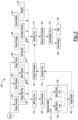
- FIG. 3 a flow diagram of an example implementation of a method 150 for modeling new designs for electromagnetic effects is shown in accordance with one or more exemplary examples.
- the method (or process) 150 is implemented by the system 100.
- the method 150 includes steps 152 to 181, as shown.
- the sequence of steps is shown as a representative example. Other step orders may be implemented to meet the criteria of a particular application.
- the design data may be stored in the memory circuit 106. Additional data may be generated in the step 154 by testing known designs 130 to generate test results 132 that are subsequently stored in the step 155. More data may be generated in the step 156 by simulating known models 134 to generate simulation results 136 that are also stored in the memory circuit 106 in the step 157. Data appropriate for the development of a new design 146 may be transferred in the step 158 to the model based system engineering tool 110.
- the model based system engineering tool 110 identifies an area of interest 138 in the new design 146.
- the area of interest 138 is usually a location where an electromagnetic disturbance (e.g., a lightning strike) is likely to occur.
- the numerical modeling tools 112 subsequently generate in the step 162 a design model 140 for the area of interest 138 in the new design 146.
- One or more design parameters 142 are extracted from the design model 140 in the step 164 by the extraction tool 114.
- the test results 132 and the know models 134 that are similar in nature to the new design 146 may be transferred to the modeling tool 116. Before, during, or after the transfer, one or more weights of the simulation results 136 may be increased in the step 168 where the simulation results 136 are related to known models 134 similar to the new design 146.
- the test results 132 and the simulation results 136 may be parsed in the step 170 among one or more training results, one or more validation results, and one or more sets of testing data.
- the modeling tool 116 (e.g., a machine learning tool, a neural network tool, an artificial intelligence tool, or the like) generate the reduced order model 144.
- the modeling tool 116 is trained by the simulation results 136 and the test results 132 from existing models and designs similar to the new design under consideration.
- the modeling tool 116 may expand the design parameters 142 based on the training.
- the reduced order model 144 is subsequently stored in the storage medium 108 in the step 174.
- the reduced order model 144 may be an ordered model.
- a format of the reduced order model 144 may be configured to feed into the statistical modeling tool 118 being used in the method 150.
- the statistical modeling tool 118) generates the new design 146 in the step 176.
- the new design 146 is stored in the storage medium 108 in the step 178.
- a map of the parameter space 148 may also be generated by the statistical modeling tool 118 in the step 180 and stored in storage medium 108 in the step 181.
- the method 150 may be performed as a single cycle.
- the resulting reduced order model 144 and/or the new design 146 may subsequently be evaluated. If appropriate, the method 150 may be repeated one or more times until the intended results are obtained.
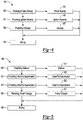
- the step 162 generally includes steps 182, 184, 186, and 188, as shown.
- the sequence of steps is shown as a representative example. Other step orders may be implemented to meet the criteria of a particular application.
- the numerical modeling tools 112 predicts a power density 183 at an edge of the new design 146 due to the electromagnetic disturbance (e.g., a lightning strike) based on the design parameters 142.
- the numerical modeling tools 112 predict, in the step 184, an ignition hazard 185 that originates from the new design 146 due to the electromagnetic disturbance based on the design parameters 142.
- the numerical modeling tools 112 predict a damage 187 to the new design 146 due to the electromagnetic disturbance also based on the design parameters 142.
- the power density 183, the ignition hazard 185, and the damage 187 are stored as part of the design model 140 in the step 188.
- the step 186 generally includes steps 190, 192, 194, 196, and 198, as shown.
- the sequence of steps is shown as a representative example. Other step orders may be implemented to meet the criteria of a particular application.
- an ablation 191 due to the electromagnetic disturbance may be predicted by the numerical modeling tools 112.
- Inter-ply delamination 193 due to the electromagnetic disturbance may be predicted by the numerical modeling tools 112 in the step 192.
- an intra-ply delamination 195 may be predicted due to the electromagnetic disturbance.
- Punch through 197 caused by the electromagnetic disturbance may be predicted in the step 196.
- the ablation 191, the inter-ply delamination 193, the intra-ply delamination 195, and the punch through 197 may be stored as part of the design model 140.
- the design parameters 142 includes a peak power density 210, a peak electrical current 220, a peak electrical current density 224, a peak temperature 226, a peak energy 228, a peak energy density 230, a peak pressure 232, a peak voltage 234, a peak electric field 236, and/or a peak magnetic field 238.
- the design parameters 142 also includes a material phase 240, a linear conductivity 242, a nonlinear conductivity 244, a relative permittivity 246, and/or a relative permeability 248.
- Additional design parameters 142 includes a specific heat 250, a thermal conductivity 252, a thermal expansion coefficients 254, fatigue margins 256, stress margins 258, damage limits 260, static margins 262, and/or stability limits 264.
- the known models 134 include one or more of anisotropic materials models 270, phase change material models 272, decomposition models 274, electrothermal models 276, and electrochemical models 278.
- the step 170 generally includes steps 280 and 288.
- the sequence of steps is shown as a representative example. Other step orders may be implemented to meet the criteria of a particular application.
- test results 132 and the simulation results 136 may be divided among training results 282, validation results 284, and testing data 286.
- Each of the training results 282, validation results 284, and testing data 286 may subsequently be presented to the modeling tool 116 in the step 288.
- FIG. 9 a schematic diagram of an example digital framework 290 to predict performance is shown in accordance with one or more exemplary examples.
- the digital framework 290 may use the model based system engineering tool 110 to predict an area of interest 138 where a lightning strike 90 is likely to occur, identify risk areas, predict damage in the structure, and determine residual strength.
- the lightning strike 90 may hit an apparatus 304 that forms a portion of an aircraft 300.
- the apparatus 304 has multiple components 304a-304b with the lightning strike 90 hitting along an edge 308 of the apparatus 304.
- the area of interest 138 further undergoes a "hot spot" analysis 320 by the electromagnetic effects solver tool 112a and the structural solver tool 112b.
- the hot spot analysis 320 may concern fasteners 310a-310b that connect the components 304a-304b of the apparatus 304 together at a joint.
- the hot spot analysis 320 determines the allowables, the fatigue margins 256, the stress margins 258, power density 183, peak electrical current 220, peak temperature 226, damage 187, and other parameters of the apparatus 304, method of installing the apparatus 304, and/or the aircraft 300.
- a structural performance analysis 322 may be performed based on the results of the hot spot analysis 320.
- the structural performance analysis 322 generally determines ignition source prediction and containment failures from mechanical forces.
- the joint analysis 340 may be used to evaluate joints in the new design 146.
- the analysis includes gathering a list of known joint types 342 from the known designs 130 and/or the known models 134.
- Parameters 344 related to the known joint types 342 may be gathered from the known designs 130 and/or the known models 134.
- the parameters 344 may include, but are not limited to, fastener diameters, ply thicknesses, numbers of fasteners, secondary containment criteria, connectivity enhancements, ultimate lightning load, and economic lightning damage load. Other parameters 344 may be used to meet the design criteria of a particular application.
- the known joint types 342 and the parameters 344 may be processed by the numerical modeling tools 112 to generate the design model 140.
- the design model 140 may include electromagnetic joint allowables 346 and structural joint allowables 348.
- a model interface/coupling 350 between the electromagnetic joint allowables 346 and structural joint allowables 348 may be included in the design model 140.
- the model interface/coupling 350 includes, but is not limited to, pressure, temperature, heat affected zones, and containment breaches.
- the numerical modeling tools 112 is used to predict the power density at the edge of a composite panel and compare the results to the values established to cause edge glow. Furthermore a coupled electromagnetic effect/structures model may be used to predict when a fastener/structure interface dissipates a sufficient amount of energy due to contact resistance and so breaches the containment and releases potential ignition hazards. This design may then be compared with a known design that has a secondary containment features, such as a cap seal.
- FIG. 11 a perspective diagram of an example area of interest 138 hit by a lightning strike 90 is shown in accordance with one or more exemplary examples.
- the apparatus 304 has visible surface damage 360 where the apparatus 304 incurred the lightning strike 90.
- the lightning strike 90 may create subsurface damage 362 around the visible surface damage 360. Heating from the lightning strike 90 may spread beyond the subsurface damage 362 into a wider volume 364 of the apparatus 304.
- Examples of the disclosure generate a database of run models that includes test results from existing designs and simulation results from existing models.
- the database may be searched for similar existing designs and/or similar existing models to provide background information.
- the new design and the background information are processed in parallel by both the electromagnetic effects solver tool 112a and the structural solver tool 112b to create the design model 140.
- the design parameters 142 are extracted from the design model 140 and subsequently feed into the modeling tool 116.
- the modeling tool 116 may be a machine learning tool, a neural network tool, an artificial intelligence tool, or the like.
- the extraction tool 114 and the modeling tool 116 may transform the design model 140 into the reduced order model 144.
- the reduced order model 144 may define algebraic equations for the new design 146.
- the coefficient of the algebraic equations may be optimized by the modeling tool 116.
- Extra weight may be given to the known models 134 that correspond to experimentally known test results 132.
- the reduced order model 144 may be transferred into the statistical modeling tool 118 to optimize a layout of the apparatus 304 and/or the aircraft 300.
- the statistical modeling tool 118 generates the map of the parameter space 148 to show where the database is sparsely populated and suggest new model builds and further test known designs.
- the techniques disclosed are useful in evaluating the allowables for electromagnetic effects and structures.
- the techniques may be integrated into a model based engineering digital thread to allow simultaneous and cross discipline effects to be captured more readily.
- the model based engineering environment also allows for the generation of a comprehensive database that houses the results from the simulations as well as existing and future test results that support, validate, and supplement the finite element modeling.
- the database of test data and models is subsequently used to extract specifics of the new design.
- the extraction may be done either manually or by model querying techniques and then applied to the finite element models and well as computer aided design and other models of the experimental tests.
- the collection of parameters generally grows and evolves over time.
- the database of parameters is regularly fed into the modeling tool 116 (e.g., machine learning tools, neural network tools, artificial intelligence tools, etc.) to create and optimize the reduced order model (e.g., algebraic equations, ordinary differential equations, and/or partial differential equations).
- the database of parameters may be split between training, validation, and testing data. The split may be 50%, 40%, and 10% respectively. Extra weight is given to models that have been validated by test.
- the map of the parameter space 148 will also inform requests for future models to be built.
- the reduced order model 144 may be available to the statistical modeling tool 118 to take the electromagnetic effects and electromagnetic effects/structures coupled performance into account and give weight in the overall architecture of the new design 146.
Landscapes
- Engineering & Computer Science (AREA)
- Physics & Mathematics (AREA)
- Geometry (AREA)
- Theoretical Computer Science (AREA)
- General Physics & Mathematics (AREA)
- Evolutionary Computation (AREA)
- Computer Hardware Design (AREA)
- General Engineering & Computer Science (AREA)
- Automation & Control Theory (AREA)
- Aviation & Aerospace Engineering (AREA)
- Computational Mathematics (AREA)
- Mathematical Analysis (AREA)
- Mathematical Optimization (AREA)
- Pure & Applied Mathematics (AREA)
- Artificial Intelligence (AREA)
- Computer Vision & Pattern Recognition (AREA)
- Medical Informatics (AREA)
- Software Systems (AREA)
- Management, Administration, Business Operations System, And Electronic Commerce (AREA)
Abstract
Description
- The disclosure relates to design modeling in general, and in particular, to modeling new designs for electromagnetic effects.
- Multidisciplinary analysis and optimization is used to study a variety of airplane architectures and design decisions. Many disciplines are incorporated into the optimization, except electromagnetic effects considerations and coupling of the electromagnetic effects to structural performance considerations. At present, the electromagnetic effects analysis takes a considerable amount of time and so lags behind the structural analysis. Accordingly, those skilled in the art continue with research and development efforts in the field of modeling designs for electromagnetic effects.
- A method for modeling a new design for electromagnetic effects is provided herein. The method includes identifying, with a model based system engineering tool executed in a computer, an area of interest in the new design where a lightning strike may occur. The new design includes a plurality of structural features and a plurality of electromagnetic features. The method further includes generating, with an electromagnetic effects solver tool and a structural solver tool, a design model for the area of interest in the new design, extracting a plurality of design parameters from the design model, and generating a reduced order model by processing the plurality of design parameters, one or more of a plurality of test results, and one or more of a plurality of simulation results with a modeling tool. The reduced order model couples the plurality of structural features with the plurality of electromagnetic features. The plurality of test results is determined by tests of a plurality of known designs that are similar to the new design. The plurality of simulation results is determined by simulations of a plurality of known models that are similar to the new design. The method further includes storing the reduced order model in a storage medium that is readable by a statistical modeling tool.
- In one or more examples of the method, the reduced order model includes one or more of an algebraic model, an ordinary differential equation model, and a partial differential equation model compatible with the statistical modeling tool.
- In one or more examples of the method, the electromagnetic effects solver tool and the structural solver tool are each a numerical modeling tool.
- In one or more examples of the method, the statistical modeling tool is a multidisciplinary analysis and optimization tool.
- In one or more examples of the method, the plurality of design parameters includes a peak power density in the area of interest due to the lightning strike, a peak electrical current in the area of interest due to the lightning strike, and a peak temperature in the area of interest due to the lightning strike.
- In one or more examples of the method, the plurality of design parameters includes one or more fatigue margins in the area of interest, one or more stress margins in the area of interest, and one or more damage limits in the area of interest.
- In one or more examples of the method, the generating of the design model includes predicting a power density at an edge of the new design due to the lightning strike based on the plurality of design parameters, predicting a damage to the new design due to the lightning strike based on the plurality of design parameters, and predicting an ignition hazard that originates from the new design due to the lightning strike based on the plurality of design parameters.
- In one or more examples, the method includes increasing one or more weights of the plurality of simulation results where the plurality of known models corresponds to the plurality of test results.
- In one or more examples of the method, the new design forms a portion of an apparatus.
- In one or more examples of the method, the apparatus is an aircraft.
- A method for modeling a new design for electromagnetic effects is provided. The method includes storing, in a memory circuit, a plurality of test results that is determined by tests of a plurality of known designs that are similar to the new design. The new design includes a plurality of structural features and a plurality of electromagnetic features. The method further includes storing a plurality of simulation results that is determined by simulations of a plurality of known models that are similar to the new design, extracting a plurality of design parameters from a design model of the new design in an area of interest where a lightning strike may occur, generating a reduced order model by processing the plurality of design parameters, one or more of the plurality of test results, and one or more of the plurality of simulation results with a modeling tool, wherein the reduced order model couples the plurality of structural features with the plurality of electromagnetic features, and storing the reduced order model in a storage medium suitable for use by a statistical modeling tool.
- In one or more examples of the method, the reduced order model includes one or more of an algebraic model, an ordinary differential equation model, and a partial differential equation model compatible with the statistical modeling tool.
- In one or more examples of the method, the statistical modeling tool is a multidisciplinary analysis and optimization tool.
- In one or more examples, the method includes parsing the plurality of test results and the plurality of simulation results among a plurality of training results, a plurality of validation results, and a plurality of testing data.
- In one or more examples, the method includes generating a map of a parameter space populated by the plurality of test results and the plurality of simulation results.
- In one or more examples of the method, the new design forms a portion of an aircraft.
- In one or more examples, the method includes identifying, with a model based system engineering tool executed in a computer, the area of interest in the new design where the lightning strike may occur, and generating, with an electromagnetic effects solver tool and a structural solver tool, the design model for the area of interest in the new design.
- A system is provided. The system includes a memory circuit and a processor. The memory circuit is configured to store a plurality of test results and a plurality of simulation results. The plurality of test results is determined by testing a plurality of known designs that are similar to a new design. The plurality of simulation results is determined by simulating a plurality of known models that are similar to the new design. The new design includes a plurality of structural features and a plurality of electromagnetic features. The processor is configured to identify an area of interest in the new design where a lightning strike may occur, generate a design model for the area of interest in the new design with an electromagnetic effects solver tool and a structural solver tool, extract a plurality of design parameters from the design model, and generate a reduced order model by processing the plurality of design parameters, one or more of the plurality of test results, and one or more of the plurality of simulation results with a modeling tool. The reduced order model couples the plurality of structural features with the plurality of electromagnetic features. The processor is further configured to store the reduced order model in a storage medium that is readable by a statistical modeling tool.
- In one or more examples of the system, the reduced order model includes one or more of an algebraic model, an ordinary differential equation model, and a partial differential equation model compatible with the statistical modeling tool, and the statistical modeling tool is a multidisciplinary analysis and optimization tool.
- In one or more examples of the system, the new design forms a portion of an aircraft.
- The above features and advantages, and other features and advantages of the present disclosure are readily apparent from the following detailed description of the best modes for carrying out the disclosure when taken in connection with the accompanying drawings.
-
-
FIG. 1 is a schematic diagram illustrating a context of a system in accordance with one or more exemplary examples. -
FIG. 2 is a schematic diagram of a modeling architecture implemented within the system in accordance with one or more exemplary examples. -
FIG. 3 is a flow diagram of a method for modeling new designs for electromagnetic effects in accordance with one or more exemplary examples. -
FIG. 4 is a flow diagram for generating a design model in accordance with one or more exemplary examples. -
FIG. 5 is a flow diagram for predicting damage in accordance with one or more exemplary examples. -
FIG. 6 is a list of design parameters of the design model in accordance with one or more exemplary examples. -
FIG. 7 is a list of model types in accordance with one or more exemplary examples. -
FIG. 8 is a flow diagram for parsing test results and simulation results in accordance with one or more exemplary examples. -
FIG. 9 is a schematic diagram of a digital framework in accordance with one or more exemplary examples. -
FIG. 10 is a schematic diagram of a joint analysis in accordance with one or more exemplary examples. -
FIG. 11 is a perspective diagram of an area of interest hit by a lightning strike in accordance with one or more exemplary examples. - Examples of the disclosure generally provide a technique for modeling new designs for electromagnetic effects. Finite element modeling capabilities for the electromagnetic effects and structures are coupled and integrated into a model based engineering architecture. A wide database of known models and supplemental test data is accessible in the model based engineering architecture and may be used to extract key parameters into a database. The database subsequently feeds a modeling tool to create a reduced order model. The reduced order model is used by a multidisciplinary analysis and optimization technique to take into account the electromagnetic effects and/or the electromagnetic effects as coupled to the structures. The integration of the finite element modeling capabilities for electromagnetic effects and structures into the model based engineering architecture may be useful in the design of an aircraft. The use of the model based engineering predicts where a lightning strike is likely to occur, identify risk areas, predict the damage in the structure, and determine residual strength of vulnerable components, such as fasteners and structural joints.
- Referring to
FIG. 1 , a schematic diagram illustrating a context of asystem 100 is shown in accordance with one or more exemplary examples. Thesystem 100 generally includes acomputer 102 having one or more processors 104 (one shown) and one or more memory circuits 106 (one shown), and one or more storage mediums 108 (one shown). - The
system 100 implements a design system. Thesystem 100 is operational to support the development of new designs for parts and installation methods for a variety of machines that are subjected to electromagnetic effects. The machines include ground vehicles, aircraft, space vehicles, water vehicles, buildings, and the like. The electromagnetic effects include lightning strikes, electrostatic discharges, and high energy radio wave exposure. - The
computer 102 implements one or more data processing computers. In examples withmultiple computers 102, theindividual computers 102 are coupled together to share data, memory space, and processing resources. Thecomputer 102 is operational to store the design data and execute software tools used to model, simulate, and create the new designs. - The
processor 104 implements one or more processors within thecomputer 102. Theprocessor 104 is in communication with thememory circuit 106 and thestorage medium 108 to exchange commands and data. Theprocessor 104 is operational to execute the software tools used to create the new designs. - The
memory circuit 106 implements one or more computer readable storage devices (e.g., random access memory, read-only memory, magnetic hard drives, solid-state drives, etc.). Thememory circuit 106 stores software programs (or tools) that are executed by theprocessor 104, and design data for one or more known designs, simulation results, known models, test results, and associated data. The tools include, but are not limited to a model based system (MBS)engineering tool 110, multiple numerical modeling tools 112 (including an electromagnetic effects (EME)solver tool 112a and astructural solver tool 112b), anextraction tool 114, amodeling tool 116, and a statistical modeling tool 118 (e.g., a multidisciplinary design and optimization (MDAO)tool 118a). In various examples, the tools 110-118a may be standard design tools. The design data includes, but is not limited to,design geometries 120,design material properties 122,structural features 124,electromagnetic features 126,design criteria 128, knowndesigns 130,test results 132, knownmodels 134, simulation results 136, a set ofweights 137, an area ofinterest 138 in the new design, adesign model 140, anddesign parameters 142. In various examples, thememory circuit 106 implements volatile memory. In other examples, thememory circuit 106 implements nonvolatile (e.g., non-transitory) memory. In still other examples, thememory circuit 106 implements a combination of volatile memory and nonvolatile memory. - The
storage medium 108 implements one or more non-transitory nonvolatile computer readable memory devices. Thestorage medium 108 is operational to store a reducedorder model 144, anew design 146, and a map of aparameter space 148. Thenew design 146 may be a design of apart 146a and/or a design of aninstallation method 146b. In various examples, thestorage medium 108 may be external to the computer 102 (as illustrated) or internal to thecomputer 102. The reducedorder model 144 includes one or more of analgebraic model 144a, an ordinarydifferential equation model 144b, and a partialdifferential equation model 144c that are compatible with thestatistical modeling tool 118. The reducedorder model 144 may be suitable for use by thestatistical modeling tool 118. - Referring to
FIG. 2 , a schematic diagram of anexample modeling architecture 149 implemented within thesystem 100 is shown in accordance with one or more exemplary examples. Themodeling architecture 149 generally includes the model basedsystem engineering tool 110, numerical modeling tools 112 (including the electromagneticeffects solver tool 112a and thestructural solver tool 112b), theextraction tool 114, themodeling tool 116, and thestatistical modeling tool 118. Themodeling architecture 149 also includes thedesign geometries 120, thedesign material properties 122, thestructural features 124, theelectromagnetic features 126, thedesign criteria 128, the known designs 130, thetest results 132, the knownmodels 134, the simulation results 136, theweights 137, the area ofinterest 138, thedesign model 140, thedesign parameters 142, the reducedorder model 144, thenew design 146, the map of theparameter space 148. - Data for the
new design 146, test results from previously tested designs, simulation results from previously modeled designs, and associated data may be stored in a database and subsequently provided to the model basedsystem engineering tool 110. The model basedsystem engineering tool 110 utilizes the received data to determine the area ofinterest 138 where an electromagnetic disturbance is likely to occur. The electromagneticeffects solver tool 112a and thestructural solver tool 112b analyzes the data in the area ofinterest 138 to create adesign model 140. Thedesign model 140 includes the structural characteristics and the electromagnetic characteristics coupled together. Theextraction tool 114 extracts thedesign parameters 142 that are subsequently provided to themodeling tool 116. - The
modeling tool 116 also received thetest results 132 and the simulation results 136. Based on thedesign parameters 142, thetest results 132 and the simulation results 136, themodeling tool 116 generates a reducedorder model 144. The reducedorder model 144 is processed by thestatistical modeling tool 118. Thestatistical modeling tool 118 generates thenew design 146, and the map of theparameter space 148. The map of theparameter space 148 is useful to determine where future models, future simulation data, and/or future test results would be beneficial in support of other new designs. - Referring to
FIG. 3 , a flow diagram of an example implementation of amethod 150 for modeling new designs for electromagnetic effects is shown in accordance with one or more exemplary examples. The method (or process) 150 is implemented by thesystem 100. Themethod 150 includessteps 152 to 181, as shown. The sequence of steps is shown as a representative example. Other step orders may be implemented to meet the criteria of a particular application. - In the
step 152, the design data may be stored in thememory circuit 106. Additional data may be generated in thestep 154 by testing knowndesigns 130 to generatetest results 132 that are subsequently stored in thestep 155. More data may be generated in thestep 156 by simulating knownmodels 134 to generatesimulation results 136 that are also stored in thememory circuit 106 in thestep 157. Data appropriate for the development of anew design 146 may be transferred in thestep 158 to the model basedsystem engineering tool 110. - In the
step 160, the model basedsystem engineering tool 110 identifies an area ofinterest 138 in thenew design 146. The area ofinterest 138 is usually a location where an electromagnetic disturbance (e.g., a lightning strike) is likely to occur. Thenumerical modeling tools 112 subsequently generate in the step 162 adesign model 140 for the area ofinterest 138 in thenew design 146. One ormore design parameters 142 are extracted from thedesign model 140 in thestep 164 by theextraction tool 114. - In the
step 166, thetest results 132 and theknow models 134 that are similar in nature to thenew design 146 may be transferred to themodeling tool 116. Before, during, or after the transfer, one or more weights of the simulation results 136 may be increased in thestep 168 where the simulation results 136 are related to knownmodels 134 similar to thenew design 146. The test results 132 and the simulation results 136 may be parsed in thestep 170 among one or more training results, one or more validation results, and one or more sets of testing data. - In the
step 172, the modeling tool 116 (e.g., a machine learning tool, a neural network tool, an artificial intelligence tool, or the like) generate the reducedorder model 144. Themodeling tool 116 is trained by the simulation results 136 and thetest results 132 from existing models and designs similar to the new design under consideration. Themodeling tool 116 may expand thedesign parameters 142 based on the training. The reducedorder model 144 is subsequently stored in thestorage medium 108 in thestep 174. The reducedorder model 144 may be an ordered model. A format of the reducedorder model 144 may be configured to feed into thestatistical modeling tool 118 being used in themethod 150. The statistical modeling tool 118) generates thenew design 146 in thestep 176. Thenew design 146 is stored in thestorage medium 108 in thestep 178. A map of theparameter space 148 may also be generated by thestatistical modeling tool 118 in thestep 180 and stored instorage medium 108 in thestep 181. - In various examples, the
method 150 may be performed as a single cycle. The resulting reducedorder model 144 and/or thenew design 146 may subsequently be evaluated. If appropriate, themethod 150 may be repeated one or more times until the intended results are obtained. - Referring to
FIG. 4 , a detailed flow diagram of an example implementation of thestep 162 for generation of the design model is shown in accordance with one or more exemplary examples. Thestep 162 generally includessteps - In the
step 182, thenumerical modeling tools 112 predicts apower density 183 at an edge of thenew design 146 due to the electromagnetic disturbance (e.g., a lightning strike) based on thedesign parameters 142. Thenumerical modeling tools 112 predict, in thestep 184, anignition hazard 185 that originates from thenew design 146 due to the electromagnetic disturbance based on thedesign parameters 142. In thestep 186, thenumerical modeling tools 112 predict adamage 187 to thenew design 146 due to the electromagnetic disturbance also based on thedesign parameters 142. Thepower density 183, theignition hazard 185, and thedamage 187 are stored as part of thedesign model 140 in thestep 188. - Referring to
FIG. 5 , a detailed flow diagram of an example implementation of thestep 186 for predicting the damage is shown in accordance with one or more exemplary examples. Thestep 186 generally includessteps - In the
step 190, anablation 191 due to the electromagnetic disturbance (e.g., a lightning strike) may be predicted by thenumerical modeling tools 112.Inter-ply delamination 193 due to the electromagnetic disturbance may be predicted by thenumerical modeling tools 112 in thestep 192. In thestep 194, anintra-ply delamination 195 may be predicted due to the electromagnetic disturbance. Punch through 197 caused by the electromagnetic disturbance may be predicted in thestep 196. In thestep 198, theablation 191, theinter-ply delamination 193, theintra-ply delamination 195, and the punch through 197 may be stored as part of thedesign model 140. - Referring to
FIG. 6 , a list of an example design parameters extracted from thedesign model 140 is shown in accordance with one or more exemplary examples. Thedesign parameters 142 includes apeak power density 210, a peak electrical current 220, a peak electricalcurrent density 224, apeak temperature 226, apeak energy 228, apeak energy density 230, apeak pressure 232, apeak voltage 234, a peakelectric field 236, and/or a peakmagnetic field 238. Thedesign parameters 142 also includes amaterial phase 240, alinear conductivity 242, anonlinear conductivity 244, arelative permittivity 246, and/or arelative permeability 248.Additional design parameters 142 includes aspecific heat 250, athermal conductivity 252, athermal expansion coefficients 254,fatigue margins 256,stress margins 258, damage limits 260,static margins 262, and/or stability limits 264. - Referring to
FIG. 7 , a list of known model types is shown in accordance with one or more exemplary examples. The knownmodels 134 include one or more ofanisotropic materials models 270, phasechange material models 272,decomposition models 274,electrothermal models 276, andelectrochemical models 278. - Referring to
FIG. 8 , a flow diagram of an example implementation of thestep 170 for parsing thetest results 132 and the simulation results 136 is shown in accordance with one or more exemplary examples. Thestep 170 generally includessteps - In the
step 280, thetest results 132 and the simulation results 136 may be divided amongtraining results 282, validation results 284, andtesting data 286. Each of the training results 282, validation results 284, andtesting data 286 may subsequently be presented to themodeling tool 116 in thestep 288. - Referring to
FIG. 9 , a schematic diagram of an exampledigital framework 290 to predict performance is shown in accordance with one or more exemplary examples. Thedigital framework 290 may use the model basedsystem engineering tool 110 to predict an area ofinterest 138 where alightning strike 90 is likely to occur, identify risk areas, predict damage in the structure, and determine residual strength. As illustrated, thelightning strike 90 may hit anapparatus 304 that forms a portion of anaircraft 300. Theapparatus 304 hasmultiple components 304a-304b with thelightning strike 90 hitting along anedge 308 of theapparatus 304. - The area of
interest 138 further undergoes a "hot spot"analysis 320 by the electromagneticeffects solver tool 112a and thestructural solver tool 112b. For example, thehot spot analysis 320 may concernfasteners 310a-310b that connect thecomponents 304a-304b of theapparatus 304 together at a joint. Thehot spot analysis 320 determines the allowables, thefatigue margins 256, thestress margins 258,power density 183, peak electrical current 220,peak temperature 226,damage 187, and other parameters of theapparatus 304, method of installing theapparatus 304, and/or theaircraft 300. - A
structural performance analysis 322 may be performed based on the results of thehot spot analysis 320. Thestructural performance analysis 322 generally determines ignition source prediction and containment failures from mechanical forces. - Referring to
FIG. 10 , a schematic diagram of an example implementation of ajoint analysis 340 is shown in accordance with one or more exemplary examples. Thejoint analysis 340 may be used to evaluate joints in thenew design 146. The analysis includes gathering a list of knownjoint types 342 from the knowndesigns 130 and/or the knownmodels 134.Parameters 344 related to the knownjoint types 342 may be gathered from the knowndesigns 130 and/or the knownmodels 134. Theparameters 344 may include, but are not limited to, fastener diameters, ply thicknesses, numbers of fasteners, secondary containment criteria, connectivity enhancements, ultimate lightning load, and economic lightning damage load.Other parameters 344 may be used to meet the design criteria of a particular application. - The known
joint types 342 and theparameters 344 may be processed by thenumerical modeling tools 112 to generate thedesign model 140. Thedesign model 140 may include electromagneticjoint allowables 346 and structuraljoint allowables 348. A model interface/coupling 350 between the electromagneticjoint allowables 346 and structuraljoint allowables 348 may be included in thedesign model 140. The model interface/coupling 350 includes, but is not limited to, pressure, temperature, heat affected zones, and containment breaches. - For the electromagnetic effects, the
numerical modeling tools 112 is used to predict the power density at the edge of a composite panel and compare the results to the values established to cause edge glow. Furthermore a coupled electromagnetic effect/structures model may be used to predict when a fastener/structure interface dissipates a sufficient amount of energy due to contact resistance and so breaches the containment and releases potential ignition hazards. This design may then be compared with a known design that has a secondary containment features, such as a cap seal. - Referring to
FIG. 11 , a perspective diagram of an example area ofinterest 138 hit by alightning strike 90 is shown in accordance with one or more exemplary examples. Theapparatus 304 hasvisible surface damage 360 where theapparatus 304 incurred thelightning strike 90. Thelightning strike 90 may createsubsurface damage 362 around thevisible surface damage 360. Heating from thelightning strike 90 may spread beyond thesubsurface damage 362 into awider volume 364 of theapparatus 304. - Examples of the disclosure generate a database of run models that includes test results from existing designs and simulation results from existing models. For a new design, the database may be searched for similar existing designs and/or similar existing models to provide background information. The new design and the background information are processed in parallel by both the electromagnetic
effects solver tool 112a and thestructural solver tool 112b to create thedesign model 140. Thedesign parameters 142 are extracted from thedesign model 140 and subsequently feed into themodeling tool 116. Themodeling tool 116 may be a machine learning tool, a neural network tool, an artificial intelligence tool, or the like. - The
extraction tool 114 and themodeling tool 116 may transform thedesign model 140 into the reducedorder model 144. In various examples, the reducedorder model 144 may define algebraic equations for thenew design 146. The coefficient of the algebraic equations may be optimized by themodeling tool 116. Extra weight may be given to the knownmodels 134 that correspond to experimentally known test results 132. - The reduced
order model 144 may be transferred into thestatistical modeling tool 118 to optimize a layout of theapparatus 304 and/or theaircraft 300. Thestatistical modeling tool 118 generates the map of theparameter space 148 to show where the database is sparsely populated and suggest new model builds and further test known designs. - The techniques disclosed are useful in evaluating the allowables for electromagnetic effects and structures. The techniques may be integrated into a model based engineering digital thread to allow simultaneous and cross discipline effects to be captured more readily. The model based engineering environment also allows for the generation of a comprehensive database that houses the results from the simulations as well as existing and future test results that support, validate, and supplement the finite element modeling. The database of test data and models is subsequently used to extract specifics of the new design. The extraction may be done either manually or by model querying techniques and then applied to the finite element models and well as computer aided design and other models of the experimental tests. The collection of parameters generally grows and evolves over time.
- The database of parameters is regularly fed into the modeling tool 116 (e.g., machine learning tools, neural network tools, artificial intelligence tools, etc.) to create and optimize the reduced order model (e.g., algebraic equations, ordinary differential equations, and/or partial differential equations). The database of parameters may be split between training, validation, and testing data. The split may be 50%, 40%, and 10% respectively. Extra weight is given to models that have been validated by test. The map of the
parameter space 148 will also inform requests for future models to be built. Finally the reducedorder model 144 may be available to thestatistical modeling tool 118 to take the electromagnetic effects and electromagnetic effects/structures coupled performance into account and give weight in the overall architecture of thenew design 146. - This disclosure is susceptible of examples in many different forms. Representative examples of the disclosure are shown in the drawings and will herein be described in detail with the understanding that these examples are provided as an exemplification of the disclosed principles, not limitations of the broad aspects of the disclosure. To that extent, elements and limitations that are described, for example, in the Abstract, Background, Summary, and Detailed Description sections, but not explicitly set forth in the claims, should not be incorporated into the claims, singly or collectively, by implication, inference or otherwise.
- For purposes of the present detailed description, unless specifically disclaimed, the singular includes the plural and vice versa. The words "and" and "or" shall be both conjunctive and disjunctive. The words "any" and "all" shall both mean "any and all", and the words "including," "containing," "comprising," "having," and the like shall each mean "including without limitation." Moreover, words of approximation such as "about," "almost," "substantially," "approximately," and "generally," may be used herein in the sense of "at, near, or nearly at," or "within 0-5% of," or "within acceptable manufacturing tolerances," or other logical combinations thereof. Referring to the drawings, wherein like reference numbers refer to like components.
- Further, the disclosure comprises examples according to the following clauses:
- Clause 1. A method (150) for modeling a new design (146) for electromagnetic effects comprising:
- identifying (160), with a model based system engineering tool (110) executed in a computer (102), an area of interest (138) in the new design (146) where a lightning strike (90) may occur, wherein the new design (146) includes a plurality of structural features (124) and a plurality of electromagnetic features (126);
- generating (162), with an electromagnetic effects solver tool (112a) and a structural solver tool (112b), a design model (140) for the area of interest (138) in the new design (146);
- extracting (164) a plurality of design parameters (142) from the design model (140);
- generating (172) a reduced order model (144) by processing the plurality of design parameters (142), one or more of a plurality of test results (132), and one or more of a plurality of simulation results (136) with a modeling tool (116), wherein
- the reduced order model (144) couples the plurality of structural features (124) with the plurality of electromagnetic features (126),
- the plurality of test results (132) is determined by tests (154) of a plurality of known designs (130) that are similar to the new design (146), and
- the plurality of simulation results (136) is determined by simulations (156) of a plurality of known models (134) that are similar to the new design (146); and
- storing (174) the reduced order model (144) in a storage medium (108) that is readable by a statistical modeling tool (118).
- Clause 2. The method (150) according to Clause 1, wherein the reduced order model (144) includes one or more of an algebraic model (144a), an ordinary differential equation model (144b), and a partial differential equation model (144c) compatible with the statistical modeling tool (118).
- Clause 3. The method (150) according to Clause 1 or 2, wherein the electromagnetic effects solver tool (112a) and the structural solver tool (112b) are each a numerical modeling tool (112).
- Clause 4. The method (150) according to any one of Clauses 1-3, wherein the statistical modeling tool (118) is a multidisciplinary analysis and optimization tool (118a).
- Clause 5. The method (150) according to any one of Clauses 1-4, wherein the plurality of design parameters (142) includes a peak power density (210) in the area of interest (138) due to the lightning strike (90), a peak electrical current (220) in the area of interest (138) due to the lightning strike (90), and a peak temperature (226) in the area of interest (138) due to the lightning strike (90).
- Clause 6. The method (150) according to any one of Clauses 1-5, wherein the plurality of design parameters (142) includes one or more fatigue margins (256) in the area of interest (138), one or more stress margins (258) in the area of interest (138), and one or more damage limits (260) in the area of interest (138).
- Clause 7. The method (150) according to any one of Clauses 1-6, wherein the generating (162) of the design model (140) includes:
- predicting (182) a power density (183) at an edge (308) of the new design (146) due to the lightning strike (90) based on the plurality of design parameters (142);
- predicting (186) a damage (187) to the new design (146) due to the lightning strike (90) based on the plurality of design parameters (142); and
- predicting (184) an ignition hazard (185) that originates from the new design (146) due to the lightning strike (90) based on the plurality of design parameters (142).
- Clause 8. The method (150) according to any one of Clauses 1-7, further comprising:
increasing (168) one or more weights (137) of the plurality of simulation results (136) where the plurality of known models (134) corresponds to the plurality of test results (132). - Clause 9. The method (150) according to any one of Clauses 1-8, wherein the new design (146) forms a portion of an apparatus (304).
- Clause 10. The method (150) according to Clause 9, wherein the apparatus (304) is an aircraft (300).
- Clause 11. A method (150) for modeling a new design (146) for electromagnetic effects comprising:
- storing (155), in a memory circuit (106), a plurality of test results (132) that is determined by tests (154) of a plurality of known designs (130) that are similar to the new design (146), wherein the new design (146) includes a plurality of structural features (124) and a plurality of electromagnetic features (126);
- storing (157) a plurality of simulation results (136) that is determined by simulations (156) of a plurality of known models (134) that are similar to the new design (146);
- extracting (164) a plurality of design parameters (142) from a design model (140) of the new design (146) in an area of interest (138) where a lightning strike (90) may occur;
- generating (172) a reduced order model (144) by processing the plurality of design parameters (142), one or more of the plurality of test results (132), and one or more of the plurality of simulation results (136) with a modeling tool (116), wherein the reduced order model (144) couples the plurality of structural features (124) with the plurality of electromagnetic features (126); and
- storing (174) the reduced order model (144) in a storage medium (108) suitable for use by a statistical modeling tool (118).
- Clause 12. The method (150) according to Clause 11, wherein the reduced order model (144) includes one or more of an algebraic model (144a), an ordinary differential equation model (144b), and a partial differential equation model (144c) compatible with the statistical modeling tool (118).
- Clause 13. The method (150) according to Clause 11 or 12, wherein the statistical modeling tool (118) is a multidisciplinary analysis and optimization tool (118a).
- Clause 14. The method (150) according to any one of Clauses 11-13, further comprising:
parsing (170) the plurality of test results (132) and the plurality of simulation results (136) among a plurality of training results (282), a plurality of validation results (284), and a plurality of testing data (286). - Clause 15. The method (150) according to any one of Clauses 11-14, further comprising:
generating (180) a map of a parameter space (148) populated by the plurality of test results (132) and the plurality of simulation results (136). - Clause 16. The method (150) according to any one of Clauses 11-15, wherein the new design (146) forms a portion of an aircraft (300).
- Clause 17. The method (150) according to any one of Clauses 11-16, further comprising:
- identifying (160), with a model based system engineering tool (110) executed in a computer (102), the area of interest (138) in the new design (146) where the lightning strike (90) may occur; and
- generating (162), with an electromagnetic effects solver tool (112a) and a structural solver tool (112b), the design model (140) for the area of interest (138) in the new design (146).
- Clause 18. A system (100) comprising:
- a memory circuit (106) configured to store a plurality of test results (132) and a plurality of simulation results (136), wherein
- the plurality of test results (132) is determined by testing (154) a plurality of known designs (130) that are similar to a new design (146),
- the plurality of simulation results (136) is determined by simulating (156) a plurality of known models (134) that are similar to the new design (146), and
- the new design (146) includes a plurality of structural features (124) and a plurality of electromagnetic features (126); and
- a processor (104) configured to:
- identify (160) an area of interest (138) in the new design (146) where a lightning strike (90) may occur;
- generate (162) a design model (140) for the area of interest (138) in the new design (146) with an electromagnetic effects solver tool (112a) and a structural solver tool (112b);
- extract (164) a plurality of design parameters (142) from the design model (140);
- generate (172) a reduced order model (144) by processing the plurality of design parameters (142), one or more of the plurality of test results (132), and one or more of the plurality of simulation results (136) with a modeling tool (116), wherein the reduced order model (144) couples the plurality of structural features (124) with the plurality of electromagnetic features (126); and
- store (174) the reduced order model (144) in a storage medium (108) that is readable by a statistical modeling tool (118).
- a memory circuit (106) configured to store a plurality of test results (132) and a plurality of simulation results (136), wherein
- Clause 19. The system (100) according to Clause 18, wherein:
- the reduced order model (144) includes one or more of an algebraic model (144a), an ordinary differential equation model (144b), and a partial differential equation model (144c) compatible with the statistical modeling tool (118); and
- the statistical modeling tool is a multidisciplinary analysis and optimization tool.
- Clause 20. The system (100) according to Clause 18 or 19, wherein the new design (146) forms a portion of an aircraft (300).
- The detailed description and the drawings or FIGS. are supportive and descriptive of the disclosure, but the scope of the disclosure is defined solely by the claims. While some of the best modes and other examples for carrying out the claimed disclosure have been described in detail, various alternative designs and examples exist for practicing the disclosure defined in the appended claims. Furthermore, the examples shown in the drawings or the characteristics of various examples mentioned in the present description are not necessarily to be understood as examples independent of each other. Rather, it is possible that each of the characteristics described in one of the examples of an example may be combined with one or a plurality of other desired characteristics from other examples, resulting in other examples not described in words or by reference to the drawings. Accordingly, such other examples fall within the framework of the scope of the appended claims.
Claims (15)
- A computer-implemented method (150) for modeling a new design (146) for electromagnetic effects comprising:identifying (160), with a model based system engineering tool (110) executed in a computer (102), an area of interest (138) in the new design (146) where a lightning strike (90) may occur, wherein the new design (146) includes a plurality of structural features (124) and a plurality of electromagnetic features (126);generating (162), with an electromagnetic effects solver tool (112a) and a structural solver tool (112b), a design model (140) for the area of interest (138) in the new design (146);extracting (164) a plurality of design parameters (142) from the design model (140);generating (172) a reduced order model (144) by processing the plurality of design parameters (142), one or more of a plurality of test results (132), and one or more of a plurality of simulation results (136) with a modeling tool (116), whereinthe reduced order model (144) couples the plurality of structural features (124) with the plurality of electromagnetic features (126),the plurality of test results (132) is determined by tests (154) of a plurality of known designs (130) that are similar to the new design (146), andthe plurality of simulation results (136) is determined by simulations (156) of a plurality of known models (134) that are similar to the new design (146); andstoring (174) the reduced order model (144) in a storage medium (108) that is readable by a statistical modeling tool (118).
- The method (150) according to claim 1, wherein the reduced order model (144) includes one or more of an algebraic model (144a), an ordinary differential equation model (144b), and a partial differential equation model (144c) compatible with the statistical modeling tool (118).
- The method (150) according to claim 1 or 2, wherein the electromagnetic effects solver tool (112a) and the structural solver tool (112b) are each a numerical modeling tool (112).
- The method (150) according to any one of claims 1-3, wherein the statistical modeling tool (118) is a multidisciplinary analysis and optimization tool (118a).
- The method (150) according to any one of claims 1-4, wherein the plurality of design parameters (142) includes a peak power density (210) in the area of interest (138) due to the lightning strike (90), a peak electrical current (220) in the area of interest (138) due to the lightning strike (90), and a peak temperature (226) in the area of interest (138) due to the lightning strike (90).
- The method (150) according to any one of claims 1-5, wherein the plurality of design parameters (142) includes one or more fatigue margins (256) in the area of interest (138), one or more stress margins (258) in the area of interest (138), and one or more damage limits (260) in the area of interest (138).
- The method (150) according to any one of claims 1-6, wherein the generating (162) of the design model (140) includes:predicting (182) a power density (183) at an edge (308) of the new design (146) due to the lightning strike (90) based on the plurality of design parameters (142);predicting (186) a damage (187) to the new design (146) due to the lightning strike (90) based on the plurality of design parameters (142); andpredicting (184) an ignition hazard (185) that originates from the new design (146) due to the lightning strike (90) based on the plurality of design parameters (142).
- The method (150) according to any one of claims 1-7, further comprising:
increasing (168) one or more weights (137) of the plurality of simulation results (136) where the plurality of known models (134) corresponds to the plurality of test results (132). - The method (150) according to any one of claims 1-8, wherein the new design (146) forms a portion of an apparatus (304).
- The method (150) according to claim 9, wherein the apparatus (304) is an aircraft (300).
- A system (100) comprising:a memory circuit (106) configured to store a plurality of test results (132) and a plurality of simulation results (136), whereinthe plurality of test results (132) is determined by testing (154) a plurality of known designs (130) that are similar to a new design (146),the plurality of simulation results (136) is determined by simulating (156) a plurality of known models (134) that are similar to the new design (146), andthe new design (146) includes a plurality of structural features (124) and a plurality of electromagnetic features (126); anda processor (104) configured to:identify (160) an area of interest (138) in the new design (146) where a lightning strike (90) may occur;generate (162) a design model (140) for the area of interest (138) in the new design (146) with an electromagnetic effects solver tool (112a) and a structural solver tool (112b);extract (164) a plurality of design parameters (142) from the design model (140);generate (172) a reduced order model (144) by processing the plurality of design parameters (142), one or more of the plurality of test results (132), and one or more of the plurality of simulation results (136) with a modeling tool (116), wherein the reduced order model (144) couples the plurality of structural features (124) with the plurality of electromagnetic features (126); andstore (174) the reduced order model (144) in a storage medium (108) that is readable by a statistical modeling tool (118).
- The system (100) according to claim 11, wherein:the reduced order model (144) includes one or more of an algebraic model (144a), an ordinary differential equation model (144b), and a partial differential equation model (144c) compatible with the statistical modeling tool (118); andthe statistical modeling tool is a multidisciplinary analysis and optimization tool.
- The system (100) according to claim 11 or 12, wherein the new design (146) forms a portion of an aircraft (300).
- The system (100) according to any one of claims 11-13, wherein the electromagnetic effects solver tool (112a) and the structural solver tool (112b) are each a numerical modeling tool (112).
- The system (100) according to any one of claims 11-14, wherein the plurality of design parameters (142) includes a peak power density (210) in the area of interest (138) due to the lightning strike (90), a peak electrical current (220) in the area of interest (138) due to the lightning strike (90), and a peak temperature (226) in the area of interest (138) due to the lightning strike (90).
Applications Claiming Priority (1)
| Application Number | Priority Date | Filing Date | Title |
|---|---|---|---|
| US17/459,316 US12106023B2 (en) | 2021-08-27 | 2021-08-27 | Modeling new designs for electromagnetic effects |
Publications (1)
| Publication Number | Publication Date |
|---|---|
| EP4141727A1 true EP4141727A1 (en) | 2023-03-01 |
Family
ID=81984803
Family Applications (1)
| Application Number | Title | Priority Date | Filing Date |
|---|---|---|---|
| EP22177764.2A Pending EP4141727A1 (en) | 2021-08-27 | 2022-06-08 | Modeling new designs for electromagnetic effects |
Country Status (5)
| Country | Link |
|---|---|
| US (1) | US12106023B2 (en) |
| EP (1) | EP4141727A1 (en) |
| JP (1) | JP2023033239A (en) |
| CN (1) | CN115730381A (en) |
| CA (1) | CA3158019A1 (en) |
Cited By (1)
| Publication number | Priority date | Publication date | Assignee | Title |
|---|---|---|---|---|
| EP4672075A1 (en) * | 2024-06-27 | 2025-12-31 | The Boeing Company | METHOD AND DEVICE FOR PRODUCING A COMPOSITE STRUCTURAL ELEMENT |
Families Citing this family (3)
| Publication number | Priority date | Publication date | Assignee | Title |
|---|---|---|---|---|
| US20230237037A1 (en) * | 2022-01-24 | 2023-07-27 | Conq, Inc. | System and method for concept creation |
| US12570409B2 (en) * | 2023-12-06 | 2026-03-10 | The Boeing Company | Methods for determining likelihoods of ignition hazards |
| CN117725756A (en) * | 2023-12-29 | 2024-03-19 | 北京树优信息技术有限公司 | A parameter determination method, device, electronic equipment and storage medium |
Family Cites Families (1)
| Publication number | Priority date | Publication date | Assignee | Title |
|---|---|---|---|---|
| CN112329149B (en) * | 2020-11-19 | 2023-10-10 | 中国航空工业集团公司沈阳飞机设计研究所 | Conduction impedance electromagnetic simulation method |
-
2021
- 2021-08-27 US US17/459,316 patent/US12106023B2/en active Active
-
2022
- 2022-05-02 CA CA3158019A patent/CA3158019A1/en active Pending
- 2022-06-08 EP EP22177764.2A patent/EP4141727A1/en active Pending
- 2022-06-20 CN CN202210696370.8A patent/CN115730381A/en active Pending
- 2022-08-26 JP JP2022134717A patent/JP2023033239A/en active Pending
Non-Patent Citations (5)
| Title |
|---|
| APRA M ET AL: "Lightning Indirect Effects Certification of a Transport Aircraft by Numerical Simulation", IEEE TRANSACTIONS ON ELECTROMAGNETIC COMPATIBILITY, IEEE SERVICE CENTER , NEW YORK , NY, US, vol. 50, no. 3, 1 August 2008 (2008-08-01), pages 513 - 523, XP011233361, ISSN: 0018-9375, DOI: 10.1109/TEMC.2008.927738 * |
| GUADALUPE GUTIERREZ GUTIERREZ ET AL: "Finite-difference time-domain method applied to lightning simulation and aircraft certification process", EMC EUROPE 2011 YORK, IEEE, 26 September 2011 (2011-09-26), pages 750 - 755, XP032020820, ISBN: 978-1-4577-1709-3 * |
| JOHN C CORBIN ET AL: "Assessment of Aircraft Susceptibility/Vulnerability to Lightning and Development of Lightning-Protection Design Criteria", IEEE TRANSACTIONS ON ELECTROMAGNETIC COMPATIBILITY, IEEE SERVICE CENTER , NEW YORK , NY, US, vol. EMC-10, no. 2, 1 May 1982 (1982-05-01), pages 225 - 237, XP011165078, ISSN: 0018-9375 * |
| LARSSON ANDERS: "The interaction between a lightning flash and an aircraft in flight", C. R. PHYSIQUE, 1 January 2002 (2002-01-01), FOI - Swedish Defence Research Agency, Grindsjön Research Centre, 14725 Tumba, Sweden, pages 1423 - 1444, XP093001517, Retrieved from the Internet <URL:https://www.sciencedirect.com/science/article/pii/S163107050201410X> [retrieved on 20221124] * |
| YANCHAO DUAN ET AL: "Research on aircraft radome lightning protection based on segmented diverter strips", 2017 INTERNATIONAL SYMPOSIUM ON ELECTROMAGNETIC COMPATIBILITY - EMC EUROPE, IEEE, 4 September 2017 (2017-09-04), pages 1 - 6, XP033246491, DOI: 10.1109/EMCEUROPE.2017.8094806 * |
Cited By (1)
| Publication number | Priority date | Publication date | Assignee | Title |
|---|---|---|---|---|
| EP4672075A1 (en) * | 2024-06-27 | 2025-12-31 | The Boeing Company | METHOD AND DEVICE FOR PRODUCING A COMPOSITE STRUCTURAL ELEMENT |
Also Published As
| Publication number | Publication date |
|---|---|
| US20230062266A1 (en) | 2023-03-02 |
| CA3158019A1 (en) | 2023-02-27 |
| CN115730381A (en) | 2023-03-03 |
| US12106023B2 (en) | 2024-10-01 |
| JP2023033239A (en) | 2023-03-09 |
Similar Documents
| Publication | Publication Date | Title |
|---|---|---|
| EP4141727A1 (en) | Modeling new designs for electromagnetic effects | |
| CN105653869A (en) | Three-dimensional transient performance analysis method for supercritical water reactor core | |
| CN102081767A (en) | Poor information theory fusion-based product life characteristic information extraction method | |
| CN109873721B (en) | Method for evaluating robustness of infrastructure network based on multi-layer complex network | |
| Mustafa et al. | Probabilistic micromechanical analysis of composite material stiffness properties for a wind turbine blade | |
| CN110266046B (en) | Electric heating micro-grid topology comprehensive diagnosis method and system based on complex network | |
| Li et al. | Taxonomic description for western Australian distribution medium‐voltage and low‐voltage feeders | |
| CN119990431A (en) | A collaborative prediction method for power system transient and voltage stability based on spatiotemporal graph neural network | |
| CN104408261A (en) | Complete vehicle electromagnetic compatibility (EMC) model building method applicable to complex automobile structure | |
| CN110047563B (en) | Composite material lightning damage simulation method and device | |
| Zhang et al. | An intelligent deformation‐based approach to the state of health estimation of collided lithium‐ion batteries for facilitating battery module safety evaluation | |
| CN101387582A (en) | A Fault Diagnosis System and Method Based on PDA | |
| Qiangwei et al. | Knowledge-data driven sampling diagnosis algorithm for lithium batteries on electric vehicles | |
| US20100204962A1 (en) | System And Method For Performing Thermal Analysis On A Building Through Universal Meshing | |
| CN119169456A (en) | A tunnel smoke and fire detection method based on mutual attention mechanism and domain adaptation | |
| Stanojević et al. | TCAD for circuits and systems: Process emulation, parasitics extraction, self-heating | |
| CN112864863B (en) | An integration method of switchboard box and secondary power supply | |
| Bapty et al. | Integrated modeling and simulation for cyberphysical systems extending multi-domain M&S to the design community. | |
| Alayande et al. | A Suitable Scheme for Influential Load Nodes Detection Considering Network Structural Risk Vulnerability Analysis. | |
| CN121328690B (en) | A Method for Constructing a 3D Virtual Model Library for Power Distribution Operations Based on Domain Knowledge Graph | |
| Cao et al. | A study of reliability assessment and topology similarity: Methodology, relationship, and applications | |
| Hu et al. | Method considering the dynamic coupling characteristic in power system for stability assessment | |
| CN121117238B (en) | Corpus database construction method and system | |
| Rasmussen | Analysis of correlations between energy consumption, structural specifications and climate-induced variables to increase energy efficiency in households and buildings through a prediction model | |
| Wang et al. | Research on information security risk assessment based on integrated influence of neighborhood |
Legal Events
| Date | Code | Title | Description |
|---|---|---|---|
| PUAI | Public reference made under article 153(3) epc to a published international application that has entered the european phase |
Free format text: ORIGINAL CODE: 0009012 |
|
| STAA | Information on the status of an ep patent application or granted ep patent |
Free format text: STATUS: THE APPLICATION HAS BEEN PUBLISHED |
|
| AK | Designated contracting states |
Kind code of ref document: A1 Designated state(s): AL AT BE BG CH CY CZ DE DK EE ES FI FR GB GR HR HU IE IS IT LI LT LU LV MC MK MT NL NO PL PT RO RS SE SI SK SM TR |
|
| RAP3 | Party data changed (applicant data changed or rights of an application transferred) |
Owner name: THE BOEING COMPANY |
|
| STAA | Information on the status of an ep patent application or granted ep patent |
Free format text: STATUS: REQUEST FOR EXAMINATION WAS MADE |
|
| 17P | Request for examination filed |
Effective date: 20230829 |
|
| RBV | Designated contracting states (corrected) |
Designated state(s): AL AT BE BG CH CY CZ DE DK EE ES FI FR GB GR HR HU IE IS IT LI LT LU LV MC MK MT NL NO PL PT RO RS SE SI SK SM TR |