EP4141626A1 - Touch frame assembly and intelligent interactive panel - Google Patents
Touch frame assembly and intelligent interactive panel Download PDFInfo
- Publication number
- EP4141626A1 EP4141626A1 EP20967858.0A EP20967858A EP4141626A1 EP 4141626 A1 EP4141626 A1 EP 4141626A1 EP 20967858 A EP20967858 A EP 20967858A EP 4141626 A1 EP4141626 A1 EP 4141626A1
- Authority
- EP
- European Patent Office
- Prior art keywords
- cover plate
- glass cover
- frame body
- touch frame
- concave surface
- Prior art date
- Legal status (The legal status is an assumption and is not a legal conclusion. Google has not performed a legal analysis and makes no representation as to the accuracy of the status listed.)
- Granted
Links
Images





Classifications
-
- G—PHYSICS
- G06—COMPUTING OR CALCULATING; COUNTING
- G06F—ELECTRIC DIGITAL DATA PROCESSING
- G06F3/00—Input arrangements for transferring data to be processed into a form capable of being handled by the computer; Output arrangements for transferring data from processing unit to output unit, e.g. interface arrangements
- G06F3/01—Input arrangements or combined input and output arrangements for interaction between user and computer
- G06F3/03—Arrangements for converting the position or the displacement of a member into a coded form
- G06F3/041—Digitisers, e.g. for touch screens or touch pads, characterised by the transducing means
-
- G—PHYSICS
- G06—COMPUTING OR CALCULATING; COUNTING
- G06F—ELECTRIC DIGITAL DATA PROCESSING
- G06F3/00—Input arrangements for transferring data to be processed into a form capable of being handled by the computer; Output arrangements for transferring data from processing unit to output unit, e.g. interface arrangements
- G06F3/01—Input arrangements or combined input and output arrangements for interaction between user and computer
- G06F3/03—Arrangements for converting the position or the displacement of a member into a coded form
- G06F3/041—Digitisers, e.g. for touch screens or touch pads, characterised by the transducing means
- G06F3/042—Digitisers, e.g. for touch screens or touch pads, characterised by the transducing means by opto-electronic means
-
- G—PHYSICS
- G06—COMPUTING OR CALCULATING; COUNTING
- G06F—ELECTRIC DIGITAL DATA PROCESSING
- G06F3/00—Input arrangements for transferring data to be processed into a form capable of being handled by the computer; Output arrangements for transferring data from processing unit to output unit, e.g. interface arrangements
- G06F3/01—Input arrangements or combined input and output arrangements for interaction between user and computer
- G06F3/03—Arrangements for converting the position or the displacement of a member into a coded form
- G06F3/041—Digitisers, e.g. for touch screens or touch pads, characterised by the transducing means
- G06F3/042—Digitisers, e.g. for touch screens or touch pads, characterised by the transducing means by opto-electronic means
- G06F3/0421—Digitisers, e.g. for touch screens or touch pads, characterised by the transducing means by opto-electronic means by interrupting or reflecting a light beam, e.g. optical touch-screen
-
- G—PHYSICS
- G06—COMPUTING OR CALCULATING; COUNTING
- G06F—ELECTRIC DIGITAL DATA PROCESSING
- G06F1/00—Details not covered by groups G06F3/00 - G06F13/00 and G06F21/00
- G06F1/16—Constructional details or arrangements
- G06F1/1601—Constructional details related to the housing of computer displays, e.g. of CRT monitors, of flat displays
-
- G—PHYSICS
- G06—COMPUTING OR CALCULATING; COUNTING
- G06F—ELECTRIC DIGITAL DATA PROCESSING
- G06F1/00—Details not covered by groups G06F3/00 - G06F13/00 and G06F21/00
- G06F1/16—Constructional details or arrangements
- G06F1/1613—Constructional details or arrangements for portable computers
- G06F1/1633—Constructional details or arrangements of portable computers not specific to the type of enclosures covered by groups G06F1/1615 - G06F1/1626
- G06F1/1637—Details related to the display arrangement, including those related to the mounting of the display in the housing
- G06F1/1643—Details related to the display arrangement, including those related to the mounting of the display in the housing the display being associated to a digitizer, e.g. laptops that can be used as penpads
-
- G—PHYSICS
- G06—COMPUTING OR CALCULATING; COUNTING
- G06F—ELECTRIC DIGITAL DATA PROCESSING
- G06F3/00—Input arrangements for transferring data to be processed into a form capable of being handled by the computer; Output arrangements for transferring data from processing unit to output unit, e.g. interface arrangements
- G06F3/01—Input arrangements or combined input and output arrangements for interaction between user and computer
- G06F3/03—Arrangements for converting the position or the displacement of a member into a coded form
- G06F3/041—Digitisers, e.g. for touch screens or touch pads, characterised by the transducing means
- G06F3/0412—Digitisers structurally integrated in a display
-
- H—ELECTRICITY
- H05—ELECTRIC TECHNIQUES NOT OTHERWISE PROVIDED FOR
- H05K—PRINTED CIRCUITS; CASINGS OR CONSTRUCTIONAL DETAILS OF ELECTRIC APPARATUS; MANUFACTURE OF ASSEMBLAGES OF ELECTRICAL COMPONENTS
- H05K1/00—Printed circuits
- H05K1/02—Details
Definitions
- the present disclosure relates to the technical field of touch display devices, in particular to a touch frame assembly and an interactive white board.
- an infrared sensing height (writing height) of the touch frame assembly is generally greater than 3.5mm, and even the infrared writing height of some products is greater than 4.5mm.
- the feeling of suspension is serious, resulting in poor writing experience.
- One of the major limitations of the infrared writing height is a control of inward concave of the glass cover plate.
- the present disclosure provides a touch frame assembly and an interactive white board in order to solve the problems of high loss of glass and high cost caused by controlling an inward concave of a glass cover plate by selecting glass in the prior art.
- the touch frame assembly comprises: an infrared touch frame, including a frame body and a PCB assembly arranged in the frame body; a glass cover plate, located on an inner side of the PCB assembly; a fixing structure, used for fixing the glass cover plate to the infrared touch frame.
- the glass cover plate controls an inward concave of the glass cover plate through a curvature of the frame and/or the fixing structure.
- Another aspect of the present disclosure provides an interactive white board, comprising a backlight module and the touch frame assembly provided above.
- the touch frame assembly comprises an infrared touch frame, a glass cover plate and a fixing structure.
- the glass cover plate After the glass cover plate is fixedly mounted on the frame body with the fixing structure, the glass cover plate will control the glass cover plate to be recessed inward through the curvature of the frame body and/or the fixing structure, so as to prevent the glass cover plate from blocking infrared signal transmission of the PCB assembly due to the convex during use, thereby ensuring a normal infrared touch operation.
- it does not need to control the inward concave of the glass cover plate by selecting glass, which can reduce the loss of glass, thereby improving the production efficiency and reducing the production cost.
- the above figures include the following reference numerals: 10. Infrared Touch Frame; 11. Frame Body; 111. First Step; 112. First Mounting Groove; 1121. Slot; 1122. Second Step; 12. PCB Assembly; 20. Glass Cover Plate; 31. Inward concave Surface; 32. Support Pad; 40. Filter Bar; 60. Fixing Piece.
- Embodiment 1 of the present disclosure provides a touch frame assembly.
- This touch frame assembly includes an infrared touch frame 10, a glass cover plate 20 and a fixing structure.
- the infrared touch frame 10 includes a frame body 11 and a PCB assembly 12 arranged in the frame body 11.
- the glass cover plate 20 is located on an inner side of the PCB assembly 12.
- An touch operation can be performed by touching the glass cover plate 20.
- the glass cover plate 20 can be fixed to the frame body 11 by the fixing structure provided between the frame body 11 and the glass cover plate 20.
- An inward concave of the glass cover plate 20 can be controlled by the curvature of the frame body 11 and the fixing structure.
- the inward concave of the glass cover plate 20 can be controlled by the curvature of the frame body 11 and the fixing structure, so as to prevent the glass cover plate 20 from blocking infrared signal transmission of the PCB assembly 12 due to the convex during use, thereby ensuring a normal operation of infrared touch.
- the display device with the above structure, such as the interactive white board, it is not necessary to control the inward concave of the glass cover plate 20 by selecting glass, which can reduce the loss of glass, thereby improving the production efficiency, simplifying the structure and reducing the low cost.
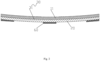
- the frame body as the frame of the display device, is formed by bending, which can be machined in various forms, such as rolling, so that the frame body 11 forms an inward concave surface and is recessed inward, and the thickness of the frame body 11 is kept consistent. As shown in Fig. 2 , the thickness of the frame body 11 is kept consistent.
- the backlight module is located inside the display device, the PCB assembly 12 is installed in the frame body 11, and the glass cover plate 20 is located on the inner side of the PCB assembly 12.
- the frame body 11 is provided with a PCB assembly 12.
- the PCB assembly 12 is provided with an infrared emission tube and an infrared receiving tube.
- Infrared rays emitted by the infrared emission tube are received by the infrared receiving tube, and an infrared matrix crossing vertically and horizontally is formed above the glass cover plate.
- a controller judges a specific position of the contact point on the screen, thereby completing the infrared touch operation.
- the glass cover plate 20 is located on the inner side of the PCB assembly 12. Since the frame body 11 is bent inward, after the glass cover plate 20 is fixedly mounted on the frame body 11, the glass cover plate 20 will be recessed inward due to the attachment of the glass cover plate 20 to the bent frame body 11. Specifically, the frame body 11 forms an inward concave arc-surface. When the glass cover plate 20 is fixedly connected with the frame body 11, the glass cover plate 20 deforms along with the inward concave of the frame body 11 to achieve the inward concave of the glass cover plate 20.
- the glass cover plate 20 is fixed on the frame body through the fixing piece 60 to maintain the inward concave of the glass cover plate 20, so as to prevent the glass cover plate 20 from blocking infrared signals emitted by the PCB assembly 12 due to the convex during use.
- a direction of the arrow in the figure indicates infrared signal transmission.
- the glass cover plate 20 is recessed inward, and the signal is normally transmitted, thereby ensuring the normal operation of the infrared touch.
- the frame body 11 is provided with an inward concave surface 31 for connecting the glass cover plate 20.
- the inward concave surface 31 is recessed toward a side of the frame body 11 facing away from the PCB assembly 12. A part of the surface of the glass cover plate 20 is attached to the inward concave surface 31.
- the fixing structure fixes the glass cover plate 20 to the infrared touch frame
- the glass cover plate 20 is kept in an inward concave state.
- the glass cover plate 20 mounted on the frame body 11 is recessed inward by a molding operation on the whole frame body 11, which is simple in structure and low in cost.
- the side of the frame body 11 facing away from the PCB assembly 12 is bent to form a depression, and the glass cover plate 20 is fixedly mounted on the frame body 11 so that the glass cover plate 20 is recessed inward. That is, the frame body 11 forms an inward concave surface 31 which is recessed inward.
- the glass cover plate 20 deforms with the depression of the frame body 11 to achieve the concave of the glass cover plate 20, thereby preventing the glass cover plate 20 from blocking the infrared signal transmission of the PCB assembly 12 due to the convex during use, and thus ensuring the normal infrared touch operation.
- the inward concave surface 31 is an arc-shaped concave surface.
- the adoption of the arc-shaped concave structure facilitates the deformation of the glass cover plate 20 by using the arc-shaped concave surface.
- the arc-shaped concave surface has a symmetrical structure, and the glass cover plate 20 can be symmetrically depressed, so that the inward concave of the glass cover plate 20 is more stable.
- a highest point of the arc-shaped concave surface is arranged corresponding to both ends of the glass cover plate 20
- a lowest point of the arc-shaped concave surface is arranged corresponding to a middle point of a long edge of the glass cover plate 20
- the highest point of the arc-shaped concave surface is arranged corresponding to both ends of the frame body 11
- the lowest point of the arc-shaped concave surface is arranged corresponding to a middle point of a long edge of the frame body 11, so that the glass cover plate 20 can achieve uniform depression, which prevents the glass cover plate 20 from a fracture due to excessive deformation of local depression.
- a length of the long edge of the glass cover plate 20 is large, it is easy to bend the glass cover plate 20 from the middle portion to the inner side, so as to bend the
- a height difference between the highest point of the arc-shaped concave surface and the lowest point of the arc-shaped concave surface is H, and H has a value range of 0.5mm-5mm. It should be pointed out that when the value of H is too small, the bending of the glass cover plate 20 is not obvious. At this time, when the glass cover plate 20 is convex, it is easy to cause that the infrared signal is unable to be transmitted normally. When the value of H is too large, it is easy to cause fracture of the glass cover plate 20. Therefore, the above value range of H is optional.
- the outer contour of the glass cover plate 20 is rectangular, and the long edge of the glass cover plate 20 is connected with the inward concave surface 31, so that the glass cover plate 20 can be easily deformed.
- the frame body 11 is a curved profile by rolling, that is, the frame body 11 is rolled to form an inner concave arc-surface, which is easy to process and low in cost. Therein, the thickness of the frame body 11 is kept consistent.
- the frame body 11 is provided with a first step 111 for supporting the glass cover plate 20.
- a part of the surface of the glass cover plate 20 is abutted against the step surface of the first step 111, and the end of the glass cover plate 20 is supported by the first step 111.
- the above structure makes the installation of the glass cover plate 20 more convenient and the abutting more stable.
- the glass cover plate 20 is fixed through the fixing structure, which can prevent the glass cover plate 20 from slipping, and the first step 111 has a positioning function to facilitate the installation of the glass cover plate 20.
- the inward concave surface 31 is provided on the step surface of the first step 111. After the glass cover plate 20 is placed in the first step 111, the inward concave of the glass cover plate 20 can be realized while using the first step 111 for positioning.
- the display device further includes a plurality of fixing pieces 60.
- Each fixing piece 60 is respectively connected with the inner surface of the glass cover plate 20 and the frame body 11, whereby the fixing pieces 60 fix the inner surface of the glass cover plate 20 and the frame body 11, so that the glass cover plate 20 is firmly fixed in the frame body 11.
- a first end of the fixing piece 60 is connected with the frame body 11 through screws, a second end of the fixing piece 60 is located above the first step 111, and the second end of the fixing piece 60 is pressed on the glass cover plate 20, so as to firmly fix the glass cover plate 20 in the frame body 11.
- the fixing pieces 60 are glass pressing blocks, and each glass pressing block is evenly distributed along the length direction of the glass cover plate 20, so that the glass cover plate 20 is stably fixed on the frame body 11.
- the glass pressing blocks can also be provided on a short edge of the glass cover plate 20, but the length of the long edge of the glass cover plate 20 is long, and the stable connection of the glass cover plate 20 can be better achieved by providing the glass pressing block on the long edge.
- the glass pressing block is locked by a locking screw, so that the glass cover plate 20 is recessed inward and fixed to the frame body 11.
- the glass cover plate 20 may be bonded to the inward concave surface 31. That is, the glass cover plate 20 is adhered in the frame body 11 with double-sided adhesive or liquid adhesive, so as to realize the fixed connection between the glass cover plate 20 and the frame body 11.
- the frame body 11 includes a first mounting groove 112, and the PCB assembly 12 is arranged in the first mounting groove 112, thereby facilitating installation and protection of the PCB assembly 12.
- a wall of the first mounting groove 112 is provided with a slot 1121 and a second step 1122.
- One end of the PCB assembly 12 is clamped with the slot 1121, and the other end of the PCB assembly 12 is bonded with a step surface of the second step 1122, so that the PCB assembly 12 is stably arranged in the first mounting groove 112, thereby avoiding shaking of the PCB assembly 12, and ensuring a normal operation of the touch operation.
- the touch frame assembly further includes a filter bar 40.
- the filter bar 40 is mounted on a notch of the first mounting groove 112.
- a side of the frame body 11 facing away from the PCB assembly 12 is bent to form a depression, and the glass cover plate 20 is fixedly mounted on the frame body 11 so that the glass cover plate 20 is recessed inward.
- the frame body 11 is fixed by a backlight module of the display device, when the glass cover plate 20 is fixedly connected in the frame body 11, the glass cover plate 20 deforms along with the depression of the frame body 11 to realize the inward concave of the glass cover plate 20, so as to prevent the glass cover plate 20 from blocking the infrared signal transmission of the PCB assembly 12 due to the convex during use, thereby ensuring a normal infrared touch operation.
- the glass cover plate 20 mounted on the frame body 11 is recessed inward by the molding operation on the whole frame body 11, which is simple in structure and low in cost.
- Embodiment 2 of the present disclosure provides a touch frame assembly.
- the difference between Embodiment 2 and Embodiment 1 is that in Embodiment 2, the thickness of the middle portion of the frame body 11 is greater than that of both ends of the frame body 11, so as to form the inward concave surface 31.
- the frame body 11 is provided with a machined surface for connecting the glass cover plate 20.
- the machined surface is an inward concave surface 31, which can be obtained by machining.
- the inward concave surface 31 can be an arc-shaped concave surface or a surface having step differences, so that the machined surface can be gradually depressed along its two ends to the middle.
- the surface of the glass cover plate 20 is attached to the inward concave surface 31.
- the glass cover plate 20 is closely attached to the inward concave surface 31, and the glass cover plate 20 is connected and fixed on the frame body 11 through the fixing piece, so that the glass cover plate 20 is bent inward, which makes the glass cover plate 20 to be recessed inward, thereby preventing the glass cover plate 20 from blocking the infrared signal emitted by the PCB assembly 12 due to its convex during use.
- the glass cover plate 20 is connected and fixed on the frame body 11 by a fixing piece, which is the same as the scheme in Embodiment 1, and will not be described herein.
- the glass cover plate 20 is attached to the inward concave surface 31, so that the glass cover plate 20 is recessed inward, thereby preventing the glass cover plate 20 from blocking the infrared signal transmission of the PCB assembly 12 due to the convex during use, and thus ensuring the normal infrared touch operation.
- it only needs to machine the inward concave surface 31 on the frame body 11, and does not need to select glass to control the inward concave of the glass cover plate 20, which can reduce the loss of glass and improve the production efficiency.
- the machining cost of the inward concave surface 31 is low and the inward concave of the glass cover plate 20 is realized, and thus the structure is simple and the cost is low.
- the thickness of the middle portion of the frame body 11 is greater than that of both ends of the frame body 11, that is, the inward concave surface 31 is formed by cutting both ends of the frame body 11, thereby making the machining of the inward concave surface 31 of the frame body more convenient.
- the outer contour of the glass cover plate 20 is rectangular, the long edge of the glass cover plate 20 is connected with the inward concave surface 31, and the length of the long edge of the glass cover plate 20 is large. Therefor, when the long edge of the glass cover plate 20 is connected with the inward concave surface 31, it is easy to make the glass cover plate 20 recess inward from the middle portion.
- the inward concave surface 31 is an arc-shaped concave surface, and the arc-shaped concave surface has a symmetrical structure, so that the glass cover plate 20 can be symmetrically recessed, which makes the glass cover plate 20 generate uniform concave deformation.
- the highest point of the arc-shaped concave surface is arranged corresponding to both ends of the glass cover plate 20, that is, the highest point of the arc-shaped concave surface is two ends of the frame body 11,or near the two ends of the frame body 11.
- the lowest point of the arc-shaped concave surface is arranged corresponding to the midpoint of the long edge of the glass cover plate 20, that is, the lowest point of the arc-shaped concave surface is the midpoint of the frame body 11 or near the midpoint of the frame body 11, which further makes the glass cover plate 20 achieve uniform depression, and prevents the glass cover plate 20 from fracture due to excessive deformation of local depression.
- H a height difference between the highest point of the arc-shaped concave surface and the lowest point of the arc-shaped concave surface. It should be pointed out that when the value of H is too small, the bending of the glass cover plate 20 is not obvious. At this time, when the glass cover plate 20 is convex, it is easy to cause that the infrared signal is unable to be transmitted normally. When the value of H is too large, it is easy to cause fracture of the glass cover plate 20. Therefore, the above value range of H is optional.
- the frame body 11 is provided with a machined surface for connecting the glass cover plate 20.
- the machined surface is an inward concave surface 31, and the inward concave surface 31 is recessed inward.
- a back surface of the glass cover plate 20 is attached to the inward concave surface 31.
- the display device with the above structure, it is only necessary to machine the frame body 11 to get the inward concave surface 31, without selecting glass to control the concave of the glass cover plate 20, which reduces the loss of glass and improves the production efficiency. Moreover, the machining cost of the inward concave surface 31 is low and the inward concave of the glass cover plate 20 is realized, and the structure is simple and the cost is low.
- Embodiment 3 of the present disclosure provides a touch frame assembly.
- the difference between Embodiment 3 and Embodiment 1 is that in Embodiment 3, a support pad 32 is provided between the glass cover plate 20 and the frame body 11.
- the support pad 32 generates a force causing the glass cover plate 20 recess inward, so that the glass cover plate 20 recesses inward.
- the outer surface of the glass cover plate 20 faces the outer side of the display device.
- the PCB assembly 12 is provided with one-to-one corresponding infrared emission tubes and infrared receiving tubes, so that an infrared matrix crossing vertically and horizontally is formed on the screen.
- the controller judges the specific position of the contact point on the screen, thereby achieving the infrared touch operation.
- the PCB assembly 12 is installed in the frame body 11, and the glass cover plate 20 is located on the inner side of the PCB assembly 12, that is, the infrared ray emitted by the infrared emission tube is located above the outer surface of the glass cover plate 20, and both ends of the glass cover plate 20 are fixedly connected in the frame body 11. Since both ends of the glass cover plate 20 are fixedly connected with the frame body 11, by arranging the support pad 32 between the frame body 11 and the glass cover plate 20, the glass cover plate 20 will be deformed under the support of the support pad 32, so that the glass cover plate 20 is recessed inward.
- the fixing structure includes a fixing piece 60, and both ends of the fixing piece 60 are respectively connected to the inner surfaces of the glass cover plate 20 and the frame body 11. Specifically, both ends of the glass cover plate 20 are fixed to the frame body 11 through the glass pressing block, and the support pad 32 forms a fulcrum.
- the glass cover plate 20 is extruded by the support pad 32, so that the glass cover plate 20 is recessed inward, so as to prevent the glass cover plate 20 from blocking the infrared signals sent by the PCB assembly 12 due to the convex during use.
- a direction of the arrow in the figure indicates the infrared signal transmission.
- the glass cover plate 20 is recessed inward, and the signal is normally transmitted, thereby ensuring normal infrared touch operation.
- the support pad 32 realizes the concave of the glass cover plate 20, which is simple in structure and low in cost.
- the outer contour of the glass cover plate 20 is rectangular, and a support pad 32 is arranged at the midpoint of the long edge of the glass cover plate 20. Since the length of the long edge of the glass cover plate 20 is large, it is easy to make the glass cover plate 20 recess inward from the middle portion, and make the glass cover plate 20 bend symmetrically, which is not easy to cause fracture of the glass cover plate 20. It should be pointed out that the support pad 32 may also be provided on the short edge of the glass cover plate 20, but the bending effect of the glass cover plate 20 is not good enough and the inward-concave degree of the glass cover plate 20 is not enough.
- a plurality of support pads 32 may be provided, and the plurality of support pads 32 may be evenly spaced.
- the support pad 32 is in the form of a block, and the ratio of the length of the support pad 32 to the length of the long edge of the glass cover plate 20 is a , wherein a value of a has a range of 1/8 to 1/12; the ratio of the thickness of the support pad 32 to the thickness of the glass cover plate 20 is b , wherein a value of b has a range of 1/3 to 1/4.
- the glass cover plate 20 will be easily fractured due to partial extrusion; if the length of the support pad 32 is too long, the contact with the glass cover plate 20 will not be sufficient when the glass cover plate 20 is extruded, and the bending effect of the glass cover plate 20 will not be obvious. If the thickness of the support pad 32 is too small, the bending and inward concave of the glass cover plate 20 is not obvious; if the thickness of the support pad 32 is too large, the glass cover plate 20 is easily fractured. Therefore, a and b in the above value range are optional.
- the support pad 32 is adhered to the frame body 11, so that the support pad 32 and the frame body 11 are stably connected.
- the support pad 32 may also be fixed to the frame body 11 by other means such as fasteners, but it is more convenient and firm to adopt the form of adhesion.
- the material of the support pad 32 is plastic or foam, so that the glass cover plate 20 is not easily damaged when the glass cover plate 20 is extruded, thereby improving the stability of the structure.
- the glass pressing blocks at both ends of the glass cover plate 20 are extruded.
- the support pad 32 in the middle portion of the glass cover plate 20 is extruded to bend the glass cover plate 20.
- the glass pressing blocks in the middle portion of the glass cover plate 20 are locked, so that the glass cover plate 20 is recessed inward and fixed on the frame body 11.
- both ends of the glass cover plate 20 are fixed to the frame body 11, and the glass cover plate 20 is extruded by the support pad 32, so that the glass cover plate 20 is recessed inward, thereby preventing the glass cover plate 20 from blocking the infrared signal transmission of the PCB assembly 12 due to the convex during use, and thus ensuring a normal infrared touch operation.
- the display device with the above structure, it is necessary to select glass to control the concave of the glass cover plate 20, which reduces the loss of glass and improves the production efficiency.
- the support pad 32 realizes the inward concave of the glass cover plate 20, which is simple in structure and low in cost.
- Embodiment 4 of the present disclosure provides an interactive white board, including a backlight module and the touch frame assembly provided above.
- the backlight module is arranged on the inner side of the touch frame assembly.
- orientation or positional relationship indicated by the orientation terms such as “front, rear, up, down, left, right", “transverse, vertical, perpendicular, horizontal " and “top, bottom” are generally based on the orientation or positional relationship shown in the drawings, which is only for the convenience of describing the present disclosure and simplifying the description. Without any contrary description, these orientation terms do not indicate and imply that the device or element referred to must have a specific orientation or be constructed and operated in a specific orientation, and therefore cannot be understood as limiting the claimed scope of the present disclosure.
- the orientation terms such as “inside, outside” refer to the inside and outside of the contour of each component itself.
- spatial terms such as “on”, “ above”, “on the upper surface”, “over”, etc., can be used herein to describe the spatial positional relationship between one element or feature and other elements or features as shown in the figure. It should be understood that the spatial term is intended to include different orientations in use or operation in addition to those described in the drawings of the element. For example, if the element in the drawing is inverted, the element described as “above other elements or structures” or “on other elements or structures” will then be positioned as “below other elements or structures” or “under other elements or structures”. Thus, the exemplary term “above” may include two orientations: “above” and “below”. The element may also be positioned in other different ways (rotated by 90 degrees or in other orientations) and the spatial relative description used herein is described accordingly.
Landscapes
- Engineering & Computer Science (AREA)
- Theoretical Computer Science (AREA)
- General Engineering & Computer Science (AREA)
- Human Computer Interaction (AREA)
- Physics & Mathematics (AREA)
- General Physics & Mathematics (AREA)
- Computer Hardware Design (AREA)
- Microelectronics & Electronic Packaging (AREA)
- Devices For Indicating Variable Information By Combining Individual Elements (AREA)
- Securing Of Glass Panes Or The Like (AREA)
Abstract
Description
- The present disclosure relates to the technical field of touch display devices, in particular to a touch frame assembly and an interactive white board.
- At present, an infrared sensing height (writing height) of the touch frame assembly is generally greater than 3.5mm, and even the infrared writing height of some products is greater than 4.5mm. When the user is writing, the feeling of suspension is serious, resulting in poor writing experience. In order to continuously improve the user's writing experience, it is an inevitable development trend to continuously reduce the touch writing height. One of the major limitations of the infrared writing height is a control of inward concave of the glass cover plate.
- Particularly, for large-sized touch panels, a deformation of the glass cover plate is more difficult to control. An installation structure of the existing glass cover plate cannot effectively control a convex of the glass cover plate. For display devices with low infrared writing height, once the convex of the glass cover plate occurs, infrared signals will be blocked, resulting in a failure of touch recognition. In the prior art, the inward concave of the glass cover plate can only be realized by selecting the glass, which causes high loss of glass, low production efficiency and high cost.
- The present disclosure provides a touch frame assembly and an interactive white board in order to solve the problems of high loss of glass and high cost caused by controlling an inward concave of a glass cover plate by selecting glass in the prior art.
- An aspect of the present disclosure provides a touch frame assembly. The touch frame assembly comprises: an infrared touch frame, including a frame body and a PCB assembly arranged in the frame body; a glass cover plate, located on an inner side of the PCB assembly; a fixing structure, used for fixing the glass cover plate to the infrared touch frame. The glass cover plate controls an inward concave of the glass cover plate through a curvature of the frame and/or the fixing structure.
- Another aspect of the present disclosure provides an interactive white board, comprising a backlight module and the touch frame assembly provided above.
- According to the technical solution of the present disclosure, the touch frame assembly comprises an infrared touch frame, a glass cover plate and a fixing structure. After the glass cover plate is fixedly mounted on the frame body with the fixing structure, the glass cover plate will control the glass cover plate to be recessed inward through the curvature of the frame body and/or the fixing structure, so as to prevent the glass cover plate from blocking infrared signal transmission of the PCB assembly due to the convex during use, thereby ensuring a normal infrared touch operation. In addition, for the display device with the above structure, it does not need to control the inward concave of the glass cover plate by selecting glass, which can reduce the loss of glass, thereby improving the production efficiency and reducing the production cost.
- The drawings which consists a part of the present disclosure are used to provide a further understanding of the present disclosure. The schematic embodiments of the present disclosure and their descriptions are used to explain the present disclosure and do not constitute an improper limitation of the present disclosure. In the drawings:
-
Fig. 1 shows a cross-sectional view of a touch frame assembly according toEmbodiment 1 of the present disclosure; -
Fig. 2 shows another cross-sectional view of a touch frame assembly provided according toEmbodiment 1 of the present disclosure; -
Fig. 3 shows a cross-sectional view of a touch frame assembly according to Embodiment 2 of the present disclosure; -
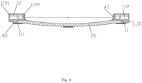
Fig. 4 shows a cross-sectional view of a touch frame assembly according to Embodiment 3 of the present disclosure; -
Fig. 5 shows another cross-sectional view of the touch frame assembly according to Embodiment 3 of the present disclosure; -
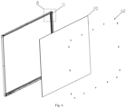
Fig. 6 shows an exploded view of a touch frame assembly provided according toEmbodiment 1 of the present disclosure; -
Fig. 7 shows a partial enlarged view at A inFig. 6 ; -
Fig. 8 shows an assembly diagram of a touch frame assembly according toEmbodiment 1 of the present disclosure; -
Fig. 9 shows a partial enlarged view at B inFig. 8 . - Therein, the above figures include the following reference numerals:
10. Infrared Touch Frame; 11. Frame Body; 111. First Step; 112. First Mounting Groove; 1121. Slot; 1122. Second Step; 12. PCB Assembly; 20. Glass Cover Plate; 31. Inward concave Surface; 32. Support Pad; 40. Filter Bar; 60. Fixing Piece. - Hereinafter, the technical solutions in the embodiments of the present disclosure will be described clearly and completely in combination with the drawings in the embodiments of the present disclosure. Definitely, the described embodiments are only a part of the embodiments of the present disclosure, not all of the embodiments. The following description of at least one exemplary embodiment in face merely illustrative, which does not serve as any limitation on the present disclosure and its application or use. Based on the embodiments of the present disclosure, all other embodiments obtained by those skilled in the art without making creative labor shall fall within the claimed scope of the present disclosure.
- As shown in
Figs. 1 and2 ,Embodiment 1 of the present disclosure provides a touch frame assembly. This touch frame assembly includes aninfrared touch frame 10, aglass cover plate 20 and a fixing structure. Theinfrared touch frame 10 includes aframe body 11 and aPCB assembly 12 arranged in theframe body 11. Theglass cover plate 20 is located on an inner side of thePCB assembly 12. An touch operation can be performed by touching theglass cover plate 20. Theglass cover plate 20 can be fixed to theframe body 11 by the fixing structure provided between theframe body 11 and theglass cover plate 20. An inward concave of theglass cover plate 20 can be controlled by the curvature of theframe body 11 and the fixing structure. - By applying the touch frame assembly provided in this embodiment, after the
glass cover plate 20 is fixed on theframe body 11 through the fixing structure, the inward concave of theglass cover plate 20 can be controlled by the curvature of theframe body 11 and the fixing structure, so as to prevent theglass cover plate 20 from blocking infrared signal transmission of thePCB assembly 12 due to the convex during use, thereby ensuring a normal operation of infrared touch. In addition, by adopting the display device with the above structure, such as the interactive white board, it is not necessary to control the inward concave of theglass cover plate 20 by selecting glass, which can reduce the loss of glass, thereby improving the production efficiency, simplifying the structure and reducing the low cost. - In this embodiment, the frame body, as the frame of the display device, is formed by bending, which can be machined in various forms, such as rolling, so that the
frame body 11 forms an inward concave surface and is recessed inward, and the thickness of theframe body 11 is kept consistent. As shown inFig. 2 , the thickness of theframe body 11 is kept consistent. In this embodiment, the backlight module is located inside the display device, thePCB assembly 12 is installed in theframe body 11, and theglass cover plate 20 is located on the inner side of thePCB assembly 12. It should be noted that theframe body 11 is provided with aPCB assembly 12. ThePCB assembly 12 is provided with an infrared emission tube and an infrared receiving tube. Infrared rays emitted by the infrared emission tube are received by the infrared receiving tube, and an infrared matrix crossing vertically and horizontally is formed above the glass cover plate. When the user touches the screen, a controller judges a specific position of the contact point on the screen, thereby completing the infrared touch operation. - As shown in
Figs. 1 and2 , theglass cover plate 20 is located on the inner side of thePCB assembly 12. Since theframe body 11 is bent inward, after theglass cover plate 20 is fixedly mounted on theframe body 11, theglass cover plate 20 will be recessed inward due to the attachment of theglass cover plate 20 to thebent frame body 11. Specifically, theframe body 11 forms an inward concave arc-surface. When theglass cover plate 20 is fixedly connected with theframe body 11, theglass cover plate 20 deforms along with the inward concave of theframe body 11 to achieve the inward concave of theglass cover plate 20. Then, theglass cover plate 20 is fixed on the frame body through the fixingpiece 60 to maintain the inward concave of theglass cover plate 20, so as to prevent theglass cover plate 20 from blocking infrared signals emitted by thePCB assembly 12 due to the convex during use. As shown inFig. 1 , a direction of the arrow in the figure indicates infrared signal transmission. At this time, theglass cover plate 20 is recessed inward, and the signal is normally transmitted, thereby ensuring the normal operation of the infrared touch. - As shown in
Fig. 2 , in this embodiment, theframe body 11 is provided with an inwardconcave surface 31 for connecting theglass cover plate 20. The inwardconcave surface 31 is recessed toward a side of theframe body 11 facing away from thePCB assembly 12. A part of the surface of theglass cover plate 20 is attached to the inwardconcave surface 31. When the fixing structure fixes theglass cover plate 20 to the infrared touch frame, theglass cover plate 20 is kept in an inward concave state. Theglass cover plate 20 mounted on theframe body 11 is recessed inward by a molding operation on thewhole frame body 11, which is simple in structure and low in cost. - Specifically, the side of the
frame body 11 facing away from thePCB assembly 12 is bent to form a depression, and theglass cover plate 20 is fixedly mounted on theframe body 11 so that theglass cover plate 20 is recessed inward. That is, theframe body 11 forms an inwardconcave surface 31 which is recessed inward. Specifically, when theglass cover plate 20 is fixedly connected in theframe body 11, theglass cover plate 20 deforms with the depression of theframe body 11 to achieve the concave of theglass cover plate 20, thereby preventing theglass cover plate 20 from blocking the infrared signal transmission of thePCB assembly 12 due to the convex during use, and thus ensuring the normal infrared touch operation. - In this embodiment, the inward
concave surface 31 is an arc-shaped concave surface. The adoption of the arc-shaped concave structure facilitates the deformation of theglass cover plate 20 by using the arc-shaped concave surface. - In this embodiment, the arc-shaped concave surface has a symmetrical structure, and the
glass cover plate 20 can be symmetrically depressed, so that the inward concave of theglass cover plate 20 is more stable. Preferably, a highest point of the arc-shaped concave surface is arranged corresponding to both ends of theglass cover plate 20, a lowest point of the arc-shaped concave surface is arranged corresponding to a middle point of a long edge of theglass cover plate 20, the highest point of the arc-shaped concave surface is arranged corresponding to both ends of theframe body 11, and the lowest point of the arc-shaped concave surface is arranged corresponding to a middle point of a long edge of theframe body 11, so that theglass cover plate 20 can achieve uniform depression, which prevents theglass cover plate 20 from a fracture due to excessive deformation of local depression. In addition, since a length of the long edge of theglass cover plate 20 is large, it is easy to bend theglass cover plate 20 from the middle portion to the inner side, so as to achieve the inward concave of theglass cover plate 20, which is an optional scheme. - In this embodiment, a height difference between the highest point of the arc-shaped concave surface and the lowest point of the arc-shaped concave surface is H, and H has a value range of 0.5mm-5mm. It should be pointed out that when the value of H is too small, the bending of the
glass cover plate 20 is not obvious. At this time, when theglass cover plate 20 is convex, it is easy to cause that the infrared signal is unable to be transmitted normally. When the value of H is too large, it is easy to cause fracture of theglass cover plate 20. Therefore, the above value range of H is optional. - In this embodiment, the outer contour of the
glass cover plate 20 is rectangular, and the long edge of theglass cover plate 20 is connected with the inwardconcave surface 31, so that theglass cover plate 20 can be easily deformed. - In this embodiment, the
frame body 11 is a curved profile by rolling, that is, theframe body 11 is rolled to form an inner concave arc-surface, which is easy to process and low in cost. Therein, the thickness of theframe body 11 is kept consistent. - As shown in
Figs. 1 ,6 and7 , theframe body 11 is provided with afirst step 111 for supporting theglass cover plate 20. A part of the surface of theglass cover plate 20 is abutted against the step surface of thefirst step 111, and the end of theglass cover plate 20 is supported by thefirst step 111. The above structure makes the installation of theglass cover plate 20 more convenient and the abutting more stable. After theglass cover plate 20 is placed in thefirst step 111, theglass cover plate 20 is fixed through the fixing structure, which can prevent theglass cover plate 20 from slipping, and thefirst step 111 has a positioning function to facilitate the installation of theglass cover plate 20. InFig. 1 , there is a gap between the end of theglass cover plate 20 and thefirst step 111. Since there is a machining error in the machining process of each component, theglass cover plate 20 can be smoothly installed into theframe body 11 by arranging the gap. - Specifically, the inward
concave surface 31 is provided on the step surface of thefirst step 111. After theglass cover plate 20 is placed in thefirst step 111, the inward concave of theglass cover plate 20 can be realized while using thefirst step 111 for positioning. - As shown in
Figs. 1 ,2 ,8 and9 , in this embodiment, the display device further includes a plurality of fixingpieces 60. Each fixingpiece 60 is respectively connected with the inner surface of theglass cover plate 20 and theframe body 11, whereby the fixingpieces 60 fix the inner surface of theglass cover plate 20 and theframe body 11, so that theglass cover plate 20 is firmly fixed in theframe body 11. - Specifically, a first end of the fixing
piece 60 is connected with theframe body 11 through screws, a second end of the fixingpiece 60 is located above thefirst step 111, and the second end of the fixingpiece 60 is pressed on theglass cover plate 20, so as to firmly fix theglass cover plate 20 in theframe body 11. - In this embodiment, the fixing
pieces 60 are glass pressing blocks, and each glass pressing block is evenly distributed along the length direction of theglass cover plate 20, so that theglass cover plate 20 is stably fixed on theframe body 11. It should be noted that the glass pressing blocks can also be provided on a short edge of theglass cover plate 20, but the length of the long edge of theglass cover plate 20 is long, and the stable connection of theglass cover plate 20 can be better achieved by providing the glass pressing block on the long edge. When theglass cover plate 20 is mounted, the glass pressing block is locked by a locking screw, so that theglass cover plate 20 is recessed inward and fixed to theframe body 11. - In other embodiments, the
glass cover plate 20 may be bonded to the inwardconcave surface 31. That is, theglass cover plate 20 is adhered in theframe body 11 with double-sided adhesive or liquid adhesive, so as to realize the fixed connection between theglass cover plate 20 and theframe body 11. - In this embodiment, the
frame body 11 includes a first mountinggroove 112, and thePCB assembly 12 is arranged in the first mountinggroove 112, thereby facilitating installation and protection of thePCB assembly 12. - Specifically, a wall of the first mounting
groove 112 is provided with aslot 1121 and asecond step 1122. One end of thePCB assembly 12 is clamped with theslot 1121, and the other end of thePCB assembly 12 is bonded with a step surface of thesecond step 1122, so that thePCB assembly 12 is stably arranged in the first mountinggroove 112, thereby avoiding shaking of thePCB assembly 12, and ensuring a normal operation of the touch operation. - In addition, the touch frame assembly further includes a
filter bar 40. In order to make thefilter bar 40 be stably connected, thefilter bar 40 is mounted on a notch of the first mountinggroove 112. - By adopting the touch frame assembly of
Embodiment 1, a side of theframe body 11 facing away from thePCB assembly 12 is bent to form a depression, and theglass cover plate 20 is fixedly mounted on theframe body 11 so that theglass cover plate 20 is recessed inward. Specifically, since theframe body 11 is fixed by a backlight module of the display device, when theglass cover plate 20 is fixedly connected in theframe body 11, theglass cover plate 20 deforms along with the depression of theframe body 11 to realize the inward concave of theglass cover plate 20, so as to prevent theglass cover plate 20 from blocking the infrared signal transmission of thePCB assembly 12 due to the convex during use, thereby ensuring a normal infrared touch operation. In addition, for the display device with the above structure, it does not need to control the inward concave of theglass cover plate 20 by selecting glass, which reduces the loss of glass and improves the production efficiency. Moreover, theglass cover plate 20 mounted on theframe body 11 is recessed inward by the molding operation on thewhole frame body 11, which is simple in structure and low in cost. - As shown in
Fig. 3 , Embodiment 2 of the present disclosure provides a touch frame assembly. The difference between Embodiment 2 andEmbodiment 1 is that in Embodiment 2, the thickness of the middle portion of theframe body 11 is greater than that of both ends of theframe body 11, so as to form the inwardconcave surface 31. - In this embodiment, the
frame body 11 is provided with a machined surface for connecting theglass cover plate 20. The machined surface is an inwardconcave surface 31, which can be obtained by machining. The inwardconcave surface 31 can be an arc-shaped concave surface or a surface having step differences, so that the machined surface can be gradually depressed along its two ends to the middle. The surface of theglass cover plate 20 is attached to the inwardconcave surface 31. At this time, theglass cover plate 20 is closely attached to the inwardconcave surface 31, and theglass cover plate 20 is connected and fixed on theframe body 11 through the fixing piece, so that theglass cover plate 20 is bent inward, which makes theglass cover plate 20 to be recessed inward, thereby preventing theglass cover plate 20 from blocking the infrared signal emitted by thePCB assembly 12 due to its convex during use. - In this embodiment, the
glass cover plate 20 is connected and fixed on theframe body 11 by a fixing piece, which is the same as the scheme inEmbodiment 1, and will not be described herein. - By applying the touch frame assembly provided in this embodiment, the
glass cover plate 20 is attached to the inwardconcave surface 31, so that theglass cover plate 20 is recessed inward, thereby preventing theglass cover plate 20 from blocking the infrared signal transmission of thePCB assembly 12 due to the convex during use, and thus ensuring the normal infrared touch operation. In addition, for the display device with the above structure, it only needs to machine the inwardconcave surface 31 on theframe body 11, and does not need to select glass to control the inward concave of theglass cover plate 20, which can reduce the loss of glass and improve the production efficiency. Moreover, the machining cost of the inwardconcave surface 31 is low and the inward concave of theglass cover plate 20 is realized, and thus the structure is simple and the cost is low. - In this embodiment, the thickness of the middle portion of the
frame body 11 is greater than that of both ends of theframe body 11, that is, the inwardconcave surface 31 is formed by cutting both ends of theframe body 11, thereby making the machining of the inwardconcave surface 31 of the frame body more convenient. The outer contour of theglass cover plate 20 is rectangular, the long edge of theglass cover plate 20 is connected with the inwardconcave surface 31, and the length of the long edge of theglass cover plate 20 is large. Therefor, when the long edge of theglass cover plate 20 is connected with the inwardconcave surface 31, it is easy to make theglass cover plate 20 recess inward from the middle portion. - Specifically, the inward
concave surface 31 is an arc-shaped concave surface, and the arc-shaped concave surface has a symmetrical structure, so that theglass cover plate 20 can be symmetrically recessed, which makes theglass cover plate 20 generate uniform concave deformation. The highest point of the arc-shaped concave surface is arranged corresponding to both ends of theglass cover plate 20, that is, the highest point of the arc-shaped concave surface is two ends of theframe body 11,or near the two ends of theframe body 11. The lowest point of the arc-shaped concave surface is arranged corresponding to the midpoint of the long edge of theglass cover plate 20, that is, the lowest point of the arc-shaped concave surface is the midpoint of theframe body 11 or near the midpoint of theframe body 11, which further makes theglass cover plate 20 achieve uniform depression, and prevents theglass cover plate 20 from fracture due to excessive deformation of local depression. - Therein, a height difference between the highest point of the arc-shaped concave surface and the lowest point of the arc-shaped concave surface is H, and H has a value range of 0.5mm-5mm. It should be pointed out that when the value of H is too small, the bending of the
glass cover plate 20 is not obvious. At this time, when theglass cover plate 20 is convex, it is easy to cause that the infrared signal is unable to be transmitted normally. When the value of H is too large, it is easy to cause fracture of theglass cover plate 20. Therefore, the above value range of H is optional. - By adopting the touch frame assembly of Embodiment 2, the
frame body 11 is provided with a machined surface for connecting theglass cover plate 20. The machined surface is an inwardconcave surface 31, and the inwardconcave surface 31 is recessed inward. A back surface of theglass cover plate 20 is attached to the inwardconcave surface 31. By fixedly connecting theglass cover plate 20 with theframe body 11 through a fixing piece, theglass cover plate 20 is recessed inward, so as to prevent theglass cover plate 20 from blocking the infrared signal transmission of thePCB assembly 12 due to the convex during use, thereby ensuring a normal infrared touch operation. In addition, by adopting the display device with the above structure, it is only necessary to machine theframe body 11 to get the inwardconcave surface 31, without selecting glass to control the concave of theglass cover plate 20, which reduces the loss of glass and improves the production efficiency. Moreover, the machining cost of the inwardconcave surface 31 is low and the inward concave of theglass cover plate 20 is realized, and the structure is simple and the cost is low. - As shown in
Figs. 4 and5 , Embodiment 3 of the present disclosure provides a touch frame assembly. The difference between Embodiment 3 andEmbodiment 1 is that in Embodiment 3, asupport pad 32 is provided between theglass cover plate 20 and theframe body 11. Thesupport pad 32 generates a force causing theglass cover plate 20 recess inward, so that theglass cover plate 20 recesses inward. - In this embodiment, the outer surface of the
glass cover plate 20 faces the outer side of the display device. It should be pointed out that thePCB assembly 12 is provided with one-to-one corresponding infrared emission tubes and infrared receiving tubes, so that an infrared matrix crossing vertically and horizontally is formed on the screen. When the user touches the screen, the controller judges the specific position of the contact point on the screen, thereby achieving the infrared touch operation. - As shown in
Figs. 4 and5 , thePCB assembly 12 is installed in theframe body 11, and theglass cover plate 20 is located on the inner side of thePCB assembly 12, that is, the infrared ray emitted by the infrared emission tube is located above the outer surface of theglass cover plate 20, and both ends of theglass cover plate 20 are fixedly connected in theframe body 11. Since both ends of theglass cover plate 20 are fixedly connected with theframe body 11, by arranging thesupport pad 32 between theframe body 11 and theglass cover plate 20, theglass cover plate 20 will be deformed under the support of thesupport pad 32, so that theglass cover plate 20 is recessed inward. - In this embodiment, the fixing structure includes a fixing
piece 60, and both ends of the fixingpiece 60 are respectively connected to the inner surfaces of theglass cover plate 20 and theframe body 11. Specifically, both ends of theglass cover plate 20 are fixed to theframe body 11 through the glass pressing block, and thesupport pad 32 forms a fulcrum. Theglass cover plate 20 is extruded by thesupport pad 32, so that theglass cover plate 20 is recessed inward, so as to prevent theglass cover plate 20 from blocking the infrared signals sent by thePCB assembly 12 due to the convex during use. As shown inFig. 4 , a direction of the arrow in the figure indicates the infrared signal transmission. At this time, theglass cover plate 20 is recessed inward, and the signal is normally transmitted, thereby ensuring normal infrared touch operation. In addition, by adopting the display device with the above structure, it is not necessary to select glass to control the concave of theglass cover plate 20, which reduces the loss of glass and improves the production efficiency. Moreover, thesupport pad 32 realizes the concave of theglass cover plate 20, which is simple in structure and low in cost. - In this embodiment, the outer contour of the
glass cover plate 20 is rectangular, and asupport pad 32 is arranged at the midpoint of the long edge of theglass cover plate 20. Since the length of the long edge of theglass cover plate 20 is large, it is easy to make theglass cover plate 20 recess inward from the middle portion, and make theglass cover plate 20 bend symmetrically, which is not easy to cause fracture of theglass cover plate 20. It should be pointed out that thesupport pad 32 may also be provided on the short edge of theglass cover plate 20, but the bending effect of theglass cover plate 20 is not good enough and the inward-concave degree of theglass cover plate 20 is not enough. - In other embodiments, a plurality of
support pads 32 may be provided, and the plurality ofsupport pads 32 may be evenly spaced. - Specifically, the
support pad 32 is in the form of a block, and the ratio of the length of thesupport pad 32 to the length of the long edge of theglass cover plate 20 is a , wherein a value of a has a range of 1/8 to 1/12; the ratio of the thickness of thesupport pad 32 to the thickness of theglass cover plate 20 is b , wherein a value of b has a range of 1/3 to 1/4. It should be pointed out that if the length of thesupport pad 32 is too small, theglass cover plate 20 will be easily fractured due to partial extrusion; if the length of thesupport pad 32 is too long, the contact with theglass cover plate 20 will not be sufficient when theglass cover plate 20 is extruded, and the bending effect of theglass cover plate 20 will not be obvious. If the thickness of thesupport pad 32 is too small, the bending and inward concave of theglass cover plate 20 is not obvious; if the thickness of thesupport pad 32 is too large, theglass cover plate 20 is easily fractured. Therefore, a and b in the above value range are optional. - In this embodiment, the
support pad 32 is adhered to theframe body 11, so that thesupport pad 32 and theframe body 11 are stably connected. In other embodiments, thesupport pad 32 may also be fixed to theframe body 11 by other means such as fasteners, but it is more convenient and firm to adopt the form of adhesion. - In this embodiment, the material of the
support pad 32 is plastic or foam, so that theglass cover plate 20 is not easily damaged when theglass cover plate 20 is extruded, thereby improving the stability of the structure. - When installing the
glass cover plate 20, firstly, the glass pressing blocks at both ends of theglass cover plate 20 are extruded. At this time, thesupport pad 32 in the middle portion of theglass cover plate 20 is extruded to bend theglass cover plate 20. Then, the glass pressing blocks in the middle portion of theglass cover plate 20 are locked, so that theglass cover plate 20 is recessed inward and fixed on theframe body 11. - By adopting the touch frame assembly of Embodiment 3, both ends of the
glass cover plate 20 are fixed to theframe body 11, and theglass cover plate 20 is extruded by thesupport pad 32, so that theglass cover plate 20 is recessed inward, thereby preventing theglass cover plate 20 from blocking the infrared signal transmission of thePCB assembly 12 due to the convex during use, and thus ensuring a normal infrared touch operation. In addition, by adopting the display device with the above structure, it is necessary to select glass to control the concave of theglass cover plate 20, which reduces the loss of glass and improves the production efficiency. Moreover, thesupport pad 32 realizes the inward concave of theglass cover plate 20, which is simple in structure and low in cost. - Embodiment 4 of the present disclosure provides an interactive white board, including a backlight module and the touch frame assembly provided above. The backlight module is arranged on the inner side of the touch frame assembly.
- It should be noted that the terms used herein are only for describing embodiments and are not intended to limit exemplary embodiments according to the present disclosure. As used herein, the singular form is also intended to include the plural form unless the context otherwise expressly indicates, and it should also be understood that when the terms "comprise" and/or "include" are used in this description, they indicate the presence of features, steps, operations, elements, components, and/or combinations thereof.
- Unless otherwise specified, the relative arrangement of components and steps, numerical expressions and numerical values set forth in these embodiments do not limit the scope of the present disclosure. At the same time, it should be understood that, for convenience of description, the dimensions of each part shown in the drawings are not drawn according to the actual scale relationship. The technologies, methods and devices known to those skilled in the art may not be discussed in detail, but in appropriate cases, the technologies, methods and devices shall be regarded as a part of the authorization described. In all the examples shown and discussed herein, any specific value should be interpreted as merely exemplary and not as a limitation. Therefore, other examples of the exemplary embodiments may have different values. It should be noted that similar reference numerals and letters indicate similar items in the following drawings. Therefore, once an item is defined in one drawing, it is not necessary to be further discussed in the following drawings.
- In the description of the present disclosure, it should be understood that the orientation or positional relationship indicated by the orientation terms such as "front, rear, up, down, left, right", "transverse, vertical, perpendicular, horizontal " and "top, bottom" are generally based on the orientation or positional relationship shown in the drawings, which is only for the convenience of describing the present disclosure and simplifying the description. Without any contrary description, these orientation terms do not indicate and imply that the device or element referred to must have a specific orientation or be constructed and operated in a specific orientation, and therefore cannot be understood as limiting the claimed scope of the present disclosure. The orientation terms such as "inside, outside" refer to the inside and outside of the contour of each component itself.
- For convenience of description, spatial terms, such as "on", " above", "on the upper surface", "over", etc., can be used herein to describe the spatial positional relationship between one element or feature and other elements or features as shown in the figure. It should be understood that the spatial term is intended to include different orientations in use or operation in addition to those described in the drawings of the element. For example, if the element in the drawing is inverted, the element described as "above other elements or structures" or "on other elements or structures" will then be positioned as "below other elements or structures" or "under other elements or structures". Thus, the exemplary term "above" may include two orientations: "above" and "below". The element may also be positioned in other different ways (rotated by 90 degrees or in other orientations) and the spatial relative description used herein is described accordingly.
- In addition, it should be noted that the terms "first" and "second" are used to define the parts, which is only for the convenience of distinguishing the corresponding parts. Unless otherwise stated, the above words have no special meaning, so they cannot be understood as limiting the claimed scope of the present disclosure.
- The above description is only the preferred embodiment of the present disclosure, and is not intended to limit the present disclosure. For those skilled in the art, the present disclosure may have various changes and variations. Any modification, equivalent replacement, improvement, etc. made within the spirit and principle of the present disclosure shall be included in the claimed scope of the present disclosure.
Claims (20)
- A touch frame assembly, characterized in that the touch frame assembly comprises:an infrared touch frame (10), including a frame body (11) and a PCB assembly (12) arranged in the frame body (11);a glass cover plate (20), located on an inner side of the PCB assembly (12);a fixing structure, used for fixing the glass cover plate (20) to the infrared touch frame (10), wherein the glass cover plate (20) controls an inward concave of the glass cover plate (20) through a curvature of the frame (11) and/or the fixing structure.
- The touch frame assembly according to claim 1, characterized in that the frame body (11) is provided with an inward concave surface (31) for cooperating with the glass cover plate (20), and a part of a surface of the glass cover plate (20) is attached to the inward concave surface (31), when the fixing structure fixes the glass cover plate (20) to the infrared touch frame (10), the glass cover plate (20) is kept in an inward concave state.
- The touch frame assembly according to claim 2, characterized in that the inward concave surface (31) is an arc-shaped concave surface.
- The touch frame assembly according to claim 3, characterized in that the arc-shaped concave surface has a symmetrical structure,a highest point of the arc-shaped concave surface is arranged corresponding to both ends of the glass cover plate (20), and a lowest point of the arc-shaped concave surface is arranged corresponding to a midpoint of a long edge of the glass cover plate (20); or,the highest point of the arc-shaped concave surface is arranged corresponding to both ends of the frame body (11), and the lowest point of the arc-shaped concave surface is arranged corresponding to a midpoint of a long edge of the frame body (11).
- The touch frame assembly according to claim 3, characterized in that
a height difference between a highest point of the arc-shaped concave surface and a lowest point of the arc-shaped concave surface is H, and H has a value range of 0.5mm-5mm. - The touch frame assembly according to claim 2, characterized in that an outer contour of the glass cover plate (20) is rectangular.
- The touch frame assembly according to claim 6, characterized in that a long edge of the glass cover plate (20) is attached to the inward concave surface (31).
- The touch frame assembly according to claim 2, characterized in thatthe fixing structure includes a fixing piece (60), one end of the fixing piece (60) is pressed on the glass cover plate (20), the other end of the fixing piece (60) is fixed on the frame body (11), so as to keep the glass cover plate (20) fixed on the infrared touch frame (10); or,the fixing structure includes an adhesive, and the glass cover plate (20) is adhered to the inward concave surface (31) through the adhesive.
- The touch frame assembly according to any one of claims 2-8, characterized in thatthe frame body (11) is a curved frame body and is recessed inward so as to form the inward concave surface (31), and a thickness of the frame body (11) is kept consistent; or,a thickness of the middle portion of the frame body (11) is greater than that of both ends of the frame body (11), so as to form the inward concave surface (31).
- The touch frame assembly according to any one of claims 2-8, characterized in that the frame body (11) is provided with a first step (111) for supporting the glass cover plate (20), a part of the surface of the glass cover plate (20) is abutted against a step surface of the first step (111), and an end of the glass cover plate (20) is supported by the first step (111).
- The touch frame assembly according to any one of claims 1-8, characterized in that the frame body (11) includes a first mounting groove (112), and the PCB assembly (12) is arranged in the first mounting groove (112).
- The touch frame assembly according to claim 11, characterized in that a wall of the first mounting groove (112) is provided with a slot (1121) and a second step (1122), one end of the PCB assembly (12) is clamped with the slot (1121), and the other end of the PCB assembly (12) is bonded with a step surface of the second step (1122).
- The touch frame assembly according to claim 11, characterized in that the touch frame assembly further comprises a filter bar (40), and the filter bar (40) is mounted on a notch of the first mounting groove (112).
- The touch frame assembly according to claim 1, characterized in that a support pad (32) is provided between the glass cover plate (20) and the frame body (11), and the support pad (32) generates a force that causes the glass cover plate (20) to be recessed inward, so that the glass cover plate (20) is recessed inward.
- The touch frame assembly according to claim 14, characterized in that an outer contour of the glass cover plate (20) is rectangular,the number of the support pad (32) is one, and the support pad (32) is arranged at a midpoint of a long edge of the glass cover plate (20); orthe number of the support pads (32) is plural, and the plurality of support pads (32) are evenly arranged at intervals.
- The touch frame assembly according to claim 14 or 15, characterized in that the support pad (32) is in the form of a block,a ratio of a length of the support pad (32) to a length of a long edge of the glass cover plate (20) is a , wherein a value of a has a range of 1/8 to 1/12; and/or,a ratio of a thickness of the support pad (32) to a thickness of the glass cover plate (20) is b, wherein a value of b has a range of 1/3 to 1/4.
- The touch frame assembly according to claim 14 or 15, characterized in that the fixing structure includes a fixing piece (60), one end of the fixing piece (60) is pressed on the glass cover plate (20), the other end of the fixing piece (60) is fixed on the frame body (11), so as to keep the glass cover plate (20) fixed on the infrared touch frame (10).
- The touch frame assembly according to claim 14 or 15, characterized in that the support pad (32) is adhered to the frame body (11).
- The touch frame assembly according to claim 14 or 15, characterized in that a material of the support pad (32) is plastic or foam.
- An interactive white board, comprising a backlight module and a touch frame assembly according to any one of claims 1-19.
Applications Claiming Priority (1)
| Application Number | Priority Date | Filing Date | Title |
|---|---|---|---|
| PCT/CN2020/142416 WO2022141520A1 (en) | 2020-12-31 | 2020-12-31 | Touch frame assembly and intelligent interactive panel |
Publications (3)
| Publication Number | Publication Date |
|---|---|
| EP4141626A1 true EP4141626A1 (en) | 2023-03-01 |
| EP4141626A4 EP4141626A4 (en) | 2023-08-09 |
| EP4141626B1 EP4141626B1 (en) | 2026-04-29 |
Family
ID=82260094
Family Applications (1)
| Application Number | Title | Priority Date | Filing Date |
|---|---|---|---|
| EP20967858.0A Active EP4141626B1 (en) | 2020-12-31 | 2020-12-31 | Touch frame assembly and intelligent interactive panel |
Country Status (6)
| Country | Link |
|---|---|
| US (1) | US12189903B2 (en) |
| EP (1) | EP4141626B1 (en) |
| JP (1) | JP7563859B2 (en) |
| KR (1) | KR102779888B1 (en) |
| CN (2) | CN115668110B (en) |
| WO (1) | WO2022141520A1 (en) |
Families Citing this family (1)
| Publication number | Priority date | Publication date | Assignee | Title |
|---|---|---|---|---|
| WO2026036845A1 (en) * | 2024-08-16 | 2026-02-19 | 深圳市鸿合创新信息技术有限责任公司 | Touch screen and display device |
Family Cites Families (35)
| Publication number | Priority date | Publication date | Assignee | Title |
|---|---|---|---|---|
| US4818859A (en) * | 1987-06-01 | 1989-04-04 | Carroll Touch Inc. | Low profile opto-device assembly with specific optoelectronic lead mount |
| JP4742351B2 (en) * | 2001-09-18 | 2011-08-10 | 株式会社リコー | Coordinate input device |
| US20150277636A1 (en) * | 2001-11-02 | 2015-10-01 | Neonode Inc. | Compound lens structure for optical touch screen |
| US20090322696A1 (en) * | 2008-06-18 | 2009-12-31 | N-Trig Ltd. | Method for assembling a digitizer sensor |
| CN102117155A (en) * | 2011-03-02 | 2011-07-06 | 广州视睿电子科技有限公司 | Concave optical touch screen |
| CN106406432A (en) * | 2011-03-21 | 2017-02-15 | 苹果公司 | Electronic device with flexible display |
| KR20140057293A (en) * | 2011-09-04 | 2014-05-12 | 네오노드, 인크. | Light actuator for movable buttons on a keypad |
| JP2013058084A (en) * | 2011-09-08 | 2013-03-28 | Nitto Denko Corp | Input display system |
| KR101319543B1 (en) * | 2012-05-17 | 2013-10-21 | 삼성디스플레이 주식회사 | Curved dispaly apparatus and multi display apparatus including the same |
| US9207800B1 (en) * | 2014-09-23 | 2015-12-08 | Neonode Inc. | Integrated light guide and touch screen frame and multi-touch determination method |
| US9323084B2 (en) * | 2012-11-08 | 2016-04-26 | Lg Display Co., Ltd. | Curved liquid crystal display device |
| JP2014232425A (en) * | 2013-05-29 | 2014-12-11 | 株式会社リコー | Input device and electronic information board system |
| JP6134442B2 (en) * | 2013-06-04 | 2017-05-24 | ネオノード インコーポレイテッド | Light touch screen |
| KR102315659B1 (en) * | 2013-11-27 | 2021-10-20 | 가부시키가이샤 한도오따이 에네루기 켄큐쇼 | Display device |
| KR102187473B1 (en) * | 2014-03-17 | 2020-12-08 | 엘지이노텍 주식회사 | Touch device |
| TWI531940B (en) * | 2014-05-08 | 2016-05-01 | 群創光電股份有限公司 | Curved touch-controlled display device and manufacturing method thereof |
| KR102333790B1 (en) * | 2015-01-23 | 2021-12-01 | 삼성디스플레이 주식회사 | Curved display device |
| EP3256936A4 (en) * | 2015-02-09 | 2018-10-17 | FlatFrog Laboratories AB | Optical touch system comprising means for projecting and detecting light beams above and inside a transmissive panel |
| KR102501102B1 (en) * | 2015-06-12 | 2023-02-20 | 삼성디스플레이 주식회사 | Curved display device and fabrication method of the same |
| US10209819B2 (en) * | 2015-12-31 | 2019-02-19 | Lg Display Co., Ltd. | Electronic device |
| CN105700214B (en) * | 2016-04-26 | 2019-03-01 | 深圳市华星光电技术有限公司 | Back board structure and flexible displays |
| KR102524906B1 (en) * | 2016-09-19 | 2023-04-26 | 삼성디스플레이 주식회사 | Display apparatus |
| KR20180037749A (en) * | 2016-10-05 | 2018-04-13 | 에스프린팅솔루션 주식회사 | Display apparatus |
| EP3667475B1 (en) * | 2016-12-07 | 2022-09-07 | FlatFrog Laboratories AB | A curved touch device |
| KR102481172B1 (en) * | 2017-12-07 | 2022-12-23 | 엘지디스플레이 주식회사 | Curved liquid Crystal Display device |
| KR102174464B1 (en) * | 2018-10-08 | 2020-11-05 | 주식회사 토비스 | Space touch detecting device and display device having the same |
| CN109884825A (en) * | 2019-02-19 | 2019-06-14 | 广州视源电子科技股份有限公司 | Touch display device, display screen and bonding method thereof |
| CN210038733U (en) * | 2019-04-18 | 2020-02-07 | 广州华欣电子科技有限公司 | Touch frame structure, touch screen and touch device |
| CN210038749U (en) * | 2019-06-12 | 2020-02-07 | 猫岐智能科技(上海)有限公司 | Touch device |
| CN210573710U (en) * | 2019-09-26 | 2020-05-19 | 广州视源电子科技股份有限公司 | Recessed display components, touch modules and intelligent interactive devices |
| US11042060B2 (en) * | 2019-10-04 | 2021-06-22 | Lg Electronics Inc. | Display device |
| CN210573725U (en) * | 2019-11-18 | 2020-05-19 | 深圳市他山石电子有限公司 | An infrared touch display tray structure |
| US11709568B2 (en) * | 2020-02-25 | 2023-07-25 | Promethean Limited | Convex interactive touch displays and related systems and methods |
| CN111766968A (en) * | 2020-06-04 | 2020-10-13 | 深圳市华星光电半导体显示技术有限公司 | Infrared display panel |
| US20220113832A1 (en) * | 2020-10-13 | 2022-04-14 | Zhenwu Huang | Touchless Display Interface System |
-
2020
- 2020-12-31 CN CN202080101177.4A patent/CN115668110B/en active Active
- 2020-12-31 EP EP20967858.0A patent/EP4141626B1/en active Active
- 2020-12-31 KR KR1020227042516A patent/KR102779888B1/en active Active
- 2020-12-31 WO PCT/CN2020/142416 patent/WO2022141520A1/en not_active Ceased
- 2020-12-31 JP JP2022574182A patent/JP7563859B2/en active Active
- 2020-12-31 CN CN202510720338.2A patent/CN120469596A/en active Pending
-
2022
- 2022-11-25 US US17/994,240 patent/US12189903B2/en active Active
Also Published As
| Publication number | Publication date |
|---|---|
| EP4141626B1 (en) | 2026-04-29 |
| KR102779888B1 (en) | 2025-03-12 |
| US20230087739A1 (en) | 2023-03-23 |
| KR20230004867A (en) | 2023-01-06 |
| CN115668110B (en) | 2025-07-08 |
| US12189903B2 (en) | 2025-01-07 |
| WO2022141520A1 (en) | 2022-07-07 |
| JP7563859B2 (en) | 2024-10-08 |
| EP4141626A4 (en) | 2023-08-09 |
| CN115668110A (en) | 2023-01-31 |
| CN120469596A (en) | 2025-08-12 |
| JP2023527900A (en) | 2023-06-30 |
Similar Documents
| Publication | Publication Date | Title |
|---|---|---|
| CN107329301B (en) | display device | |
| US20070115401A1 (en) | Display device | |
| CN206020871U (en) | Ultra-thin display module and display device | |
| CN210605673U (en) | Touch frame and touch screen comprising same | |
| US9220174B2 (en) | Pedestal for flat panel display device and flat panel display device | |
| CN111028691B (en) | Flexible display panel and electronic equipment | |
| CN116669364B (en) | Housing and electronic equipment | |
| US12189903B2 (en) | Touch frame assembly and interactive white board | |
| CN216434585U (en) | Display module and display device | |
| CN206147212U (en) | Liquid crystal display device | |
| TWM482084U (en) | Plastic-frame-absent frame type back board structure | |
| CN101539677B (en) | Liquid crystal display device | |
| CN110696734A (en) | Locking mechanism of multi-function vehicle carries panel computer support | |
| US20090080179A1 (en) | Backlight unit, and a display device including the same | |
| CN210720949U (en) | Liquid crystal display device and direct type backlight module and back plate thereof | |
| CN221573394U (en) | Backlight module and display device | |
| CN105759501B (en) | Lamp strip mounting structure of direct type display device | |
| CN221008509U (en) | Interactive display device and intelligent blackboard | |
| CN119127007B (en) | Intelligent interaction touch panel based on glue-free lamination | |
| CN217718379U (en) | Backlight module and display device | |
| CN217588363U (en) | LCD screen mounting structure | |
| CN217279717U (en) | Express cabinet | |
| CN219842604U (en) | Improve and press white and dirt-proof liquid crystal display | |
| KR102698779B1 (en) | Electronic blackboard with non-adhesive assembly structure of video panel and protective glass plate | |
| CN220290198U (en) | Mounting, diaphragm fixed knot constructs and mutual dull and stereotyped |
Legal Events
| Date | Code | Title | Description |
|---|---|---|---|
| STAA | Information on the status of an ep patent application or granted ep patent |
Free format text: STATUS: THE INTERNATIONAL PUBLICATION HAS BEEN MADE |
|
| PUAI | Public reference made under article 153(3) epc to a published international application that has entered the european phase |
Free format text: ORIGINAL CODE: 0009012 |
|
| STAA | Information on the status of an ep patent application or granted ep patent |
Free format text: STATUS: REQUEST FOR EXAMINATION WAS MADE |
|
| 17P | Request for examination filed |
Effective date: 20221122 |
|
| AK | Designated contracting states |
Kind code of ref document: A1 Designated state(s): AL AT BE BG CH CY CZ DE DK EE ES FI FR GB GR HR HU IE IS IT LI LT LU LV MC MK MT NL NO PL PT RO RS SE SI SK SM TR |
|
| A4 | Supplementary search report drawn up and despatched |
Effective date: 20230710 |
|
| RIC1 | Information provided on ipc code assigned before grant |
Ipc: G06F 3/042 20060101ALI20230704BHEP Ipc: G06F 1/16 20060101ALI20230704BHEP Ipc: G06F 3/041 20060101AFI20230704BHEP |
|
| DAV | Request for validation of the european patent (deleted) | ||
| DAX | Request for extension of the european patent (deleted) | ||
| GRAP | Despatch of communication of intention to grant a patent |
Free format text: ORIGINAL CODE: EPIDOSNIGR1 |
|
| STAA | Information on the status of an ep patent application or granted ep patent |
Free format text: STATUS: GRANT OF PATENT IS INTENDED |
|
| INTG | Intention to grant announced |
Effective date: 20251125 |
|
| GRAJ | Information related to disapproval of communication of intention to grant by the applicant or resumption of examination proceedings by the epo deleted |
Free format text: ORIGINAL CODE: EPIDOSDIGR1 |
|
| STAA | Information on the status of an ep patent application or granted ep patent |
Free format text: STATUS: REQUEST FOR EXAMINATION WAS MADE |
|
| GRAP | Despatch of communication of intention to grant a patent |
Free format text: ORIGINAL CODE: EPIDOSNIGR1 |
|
| STAA | Information on the status of an ep patent application or granted ep patent |
Free format text: STATUS: GRANT OF PATENT IS INTENDED |
|
| INTC | Intention to grant announced (deleted) | ||
| INTG | Intention to grant announced |
Effective date: 20260217 |
|
| P01 | Opt-out of the competence of the unified patent court (upc) registered |
Free format text: CASE NUMBER: UPC_APP_0004540_4141626/2026 Effective date: 20260209 |
|
| GRAS | Grant fee paid |
Free format text: ORIGINAL CODE: EPIDOSNIGR3 |
|
| GRAA | (expected) grant |
Free format text: ORIGINAL CODE: 0009210 |
|
| STAA | Information on the status of an ep patent application or granted ep patent |
Free format text: STATUS: THE PATENT HAS BEEN GRANTED |
|
| AK | Designated contracting states |
Kind code of ref document: B1 Designated state(s): AL AT BE BG CH CY CZ DE DK EE ES FI FR GB GR HR HU IE IS IT LI LT LU LV MC MK MT NL NO PL PT RO RS SE SI SK SM TR |
|
| REG | Reference to a national code |
Ref country code: CH Ref legal event code: F10 Free format text: ST27 STATUS EVENT CODE: U-0-0-F10-F00 (AS PROVIDED BY THE NATIONAL OFFICE) Effective date: 20260429 Ref country code: GB Ref legal event code: FG4D |