EP4141609A1 - Proactive thermal management system - Google Patents
Proactive thermal management system Download PDFInfo
- Publication number
- EP4141609A1 EP4141609A1 EP22192958.1A EP22192958A EP4141609A1 EP 4141609 A1 EP4141609 A1 EP 4141609A1 EP 22192958 A EP22192958 A EP 22192958A EP 4141609 A1 EP4141609 A1 EP 4141609A1
- Authority
- EP
- European Patent Office
- Prior art keywords
- component
- identified
- coolant flow
- imminent
- identifying
- Prior art date
- Legal status (The legal status is an assumption and is not a legal conclusion. Google has not performed a legal analysis and makes no representation as to the accuracy of the status listed.)
- Granted
Links
Images


Classifications
-
- G—PHYSICS
- G05—CONTROLLING; REGULATING
- G05D—SYSTEMS FOR CONTROLLING OR REGULATING NON-ELECTRIC VARIABLES
- G05D23/00—Control of temperature
- G05D23/19—Control of temperature characterised by the use of electric means
- G05D23/1919—Control of temperature characterised by the use of electric means characterised by the type of controller
-
- B—PERFORMING OPERATIONS; TRANSPORTING
- B60—VEHICLES IN GENERAL
- B60L—PROPULSION OF ELECTRICALLY-PROPELLED VEHICLES; SUPPLYING ELECTRIC POWER FOR AUXILIARY EQUIPMENT OF ELECTRICALLY-PROPELLED VEHICLES; ELECTRODYNAMIC BRAKE SYSTEMS FOR VEHICLES IN GENERAL; MAGNETIC SUSPENSION OR LEVITATION FOR VEHICLES; MONITORING OPERATING VARIABLES OF ELECTRICALLY-PROPELLED VEHICLES; ELECTRIC SAFETY DEVICES FOR ELECTRICALLY-PROPELLED VEHICLES
- B60L58/00—Methods or circuit arrangements for monitoring or controlling batteries or fuel cells, specially adapted for electric vehicles
- B60L58/10—Methods or circuit arrangements for monitoring or controlling batteries or fuel cells, specially adapted for electric vehicles for monitoring or controlling batteries
- B60L58/24—Methods or circuit arrangements for monitoring or controlling batteries or fuel cells, specially adapted for electric vehicles for monitoring or controlling batteries for controlling the temperature of batteries
-
- B—PERFORMING OPERATIONS; TRANSPORTING
- B64—AIRCRAFT; AVIATION; COSMONAUTICS
- B64D—EQUIPMENT FOR FITTING IN OR TO AIRCRAFT; FLIGHT SUITS; PARACHUTES; ARRANGEMENT OR MOUNTING OF POWER PLANTS OR PROPULSION TRANSMISSIONS IN AIRCRAFT
- B64D27/00—Arrangement or mounting of power plants in aircraft; Aircraft characterised by the type or position of power plants
- B64D27/02—Aircraft characterised by the type or position of power plants
- B64D27/30—Aircraft characterised by electric power plants
- B64D27/34—All-electric aircraft
-
- B—PERFORMING OPERATIONS; TRANSPORTING
- B64—AIRCRAFT; AVIATION; COSMONAUTICS
- B64D—EQUIPMENT FOR FITTING IN OR TO AIRCRAFT; FLIGHT SUITS; PARACHUTES; ARRANGEMENT OR MOUNTING OF POWER PLANTS OR PROPULSION TRANSMISSIONS IN AIRCRAFT
- B64D27/00—Arrangement or mounting of power plants in aircraft; Aircraft characterised by the type or position of power plants
- B64D27/02—Aircraft characterised by the type or position of power plants
- B64D27/30—Aircraft characterised by electric power plants
- B64D27/35—Arrangements for on-board electric energy production, distribution, recovery or storage
- B64D27/357—Arrangements for on-board electric energy production, distribution, recovery or storage using batteries
-
- B—PERFORMING OPERATIONS; TRANSPORTING
- B64—AIRCRAFT; AVIATION; COSMONAUTICS
- B64D—EQUIPMENT FOR FITTING IN OR TO AIRCRAFT; FLIGHT SUITS; PARACHUTES; ARRANGEMENT OR MOUNTING OF POWER PLANTS OR PROPULSION TRANSMISSIONS IN AIRCRAFT
- B64D33/00—Arrangement in aircraft of power plant parts or auxiliaries not otherwise provided for
- B64D33/08—Arrangement in aircraft of power plant parts or auxiliaries not otherwise provided for of power plant cooling systems
-
- G—PHYSICS
- G07—CHECKING-DEVICES
- G07C—TIME OR ATTENDANCE REGISTERS; REGISTERING OR INDICATING THE WORKING OF MACHINES; GENERATING RANDOM NUMBERS; VOTING OR LOTTERY APPARATUS; ARRANGEMENTS, SYSTEMS OR APPARATUS FOR CHECKING NOT PROVIDED FOR ELSEWHERE
- G07C5/00—Registering or indicating the working of vehicles
- G07C5/02—Registering or indicating driving, working, idle, or waiting time only
-
- H—ELECTRICITY
- H01—ELECTRIC ELEMENTS
- H01M—PROCESSES OR MEANS, e.g. BATTERIES, FOR THE DIRECT CONVERSION OF CHEMICAL ENERGY INTO ELECTRICAL ENERGY
- H01M10/00—Secondary cells; Manufacture thereof
- H01M10/60—Heating or cooling; Temperature control
- H01M10/61—Types of temperature control
- H01M10/613—Cooling or keeping cold
-
- H—ELECTRICITY
- H01—ELECTRIC ELEMENTS
- H01M—PROCESSES OR MEANS, e.g. BATTERIES, FOR THE DIRECT CONVERSION OF CHEMICAL ENERGY INTO ELECTRICAL ENERGY
- H01M10/00—Secondary cells; Manufacture thereof
- H01M10/60—Heating or cooling; Temperature control
- H01M10/62—Heating or cooling; Temperature control specially adapted for specific applications
- H01M10/625—Vehicles
-
- H—ELECTRICITY
- H01—ELECTRIC ELEMENTS
- H01M—PROCESSES OR MEANS, e.g. BATTERIES, FOR THE DIRECT CONVERSION OF CHEMICAL ENERGY INTO ELECTRICAL ENERGY
- H01M10/00—Secondary cells; Manufacture thereof
- H01M10/60—Heating or cooling; Temperature control
- H01M10/63—Control systems
- H01M10/633—Control systems characterised by algorithms, flow charts, software details or the like
-
- H—ELECTRICITY
- H01—ELECTRIC ELEMENTS
- H01M—PROCESSES OR MEANS, e.g. BATTERIES, FOR THE DIRECT CONVERSION OF CHEMICAL ENERGY INTO ELECTRICAL ENERGY
- H01M10/00—Secondary cells; Manufacture thereof
- H01M10/60—Heating or cooling; Temperature control
- H01M10/65—Means for temperature control structurally associated with the cells
- H01M10/656—Means for temperature control structurally associated with the cells characterised by the type of heat-exchange fluid
- H01M10/6567—Liquids
- H01M10/6568—Liquids characterised by flow circuits, e.g. loops, located externally to the cells or cell casings
-
- B—PERFORMING OPERATIONS; TRANSPORTING
- B60—VEHICLES IN GENERAL
- B60L—PROPULSION OF ELECTRICALLY-PROPELLED VEHICLES; SUPPLYING ELECTRIC POWER FOR AUXILIARY EQUIPMENT OF ELECTRICALLY-PROPELLED VEHICLES; ELECTRODYNAMIC BRAKE SYSTEMS FOR VEHICLES IN GENERAL; MAGNETIC SUSPENSION OR LEVITATION FOR VEHICLES; MONITORING OPERATING VARIABLES OF ELECTRICALLY-PROPELLED VEHICLES; ELECTRIC SAFETY DEVICES FOR ELECTRICALLY-PROPELLED VEHICLES
- B60L2200/00—Type of vehicles
- B60L2200/10—Air crafts
-
- B—PERFORMING OPERATIONS; TRANSPORTING
- B60—VEHICLES IN GENERAL
- B60L—PROPULSION OF ELECTRICALLY-PROPELLED VEHICLES; SUPPLYING ELECTRIC POWER FOR AUXILIARY EQUIPMENT OF ELECTRICALLY-PROPELLED VEHICLES; ELECTRODYNAMIC BRAKE SYSTEMS FOR VEHICLES IN GENERAL; MAGNETIC SUSPENSION OR LEVITATION FOR VEHICLES; MONITORING OPERATING VARIABLES OF ELECTRICALLY-PROPELLED VEHICLES; ELECTRIC SAFETY DEVICES FOR ELECTRICALLY-PROPELLED VEHICLES
- B60L2240/00—Control parameters of input or output; Target parameters
- B60L2240/40—Drive Train control parameters
- B60L2240/42—Drive Train control parameters related to electric machines
- B60L2240/425—Temperature
-
- B—PERFORMING OPERATIONS; TRANSPORTING
- B60—VEHICLES IN GENERAL
- B60L—PROPULSION OF ELECTRICALLY-PROPELLED VEHICLES; SUPPLYING ELECTRIC POWER FOR AUXILIARY EQUIPMENT OF ELECTRICALLY-PROPELLED VEHICLES; ELECTRODYNAMIC BRAKE SYSTEMS FOR VEHICLES IN GENERAL; MAGNETIC SUSPENSION OR LEVITATION FOR VEHICLES; MONITORING OPERATING VARIABLES OF ELECTRICALLY-PROPELLED VEHICLES; ELECTRIC SAFETY DEVICES FOR ELECTRICALLY-PROPELLED VEHICLES
- B60L2240/00—Control parameters of input or output; Target parameters
- B60L2240/40—Drive Train control parameters
- B60L2240/54—Drive Train control parameters related to batteries
- B60L2240/545—Temperature
-
- H—ELECTRICITY
- H01—ELECTRIC ELEMENTS
- H01M—PROCESSES OR MEANS, e.g. BATTERIES, FOR THE DIRECT CONVERSION OF CHEMICAL ENERGY INTO ELECTRICAL ENERGY
- H01M2220/00—Batteries for particular applications
- H01M2220/20—Batteries in motive systems, e.g. vehicle, ship, plane
Definitions
- a propeller motor and a battery powering the propeller motor both generate heat during operation and can overheat (surpass an upper temperature limit) if left uncooled.
- Certain components, such as the battery also may have a lower temperature limit to operate properly. Accordingly, the aircraft is equipped with a thermal management system including cooling circuits for these components.
- each component may have a normal operating temperature based on normal power consumption during the flight and peak operating temperatures resulting from specific events occurring during the flight.
- the heat of a motor and/or inverter of a propeller arrangement of the aircraft may increase during take off, landing, hovering, or turning of the aircraft compared to the temperature during cruising.
- the heat of the battery also may cycle based on how much power is drawn by the propeller arrangements or other components during the flight. Accordingly, the thermal management system is typically configured to provide sufficient cooling for the expected elevated temperatures.
- Some aspects of the disclosure are directed to a thermal management system configured to provide proactive cooling to one or more components of a power system to mitigate the temperature cycle of the component during a high power event (e.g., take off, landing, hovering, turning, etc.).
- a high power event e.g., take off, landing, hovering, turning, etc.
- the peak operating temperature of the component may be reduced. Accordingly, the maximum output of the thermal management system 120 required to combat these peak operating temperatures also may be mitigated, which allows for smaller/lighter components of the thermal management system 120.
- the flow rate of the coolant needing to pass over a component during a high power event may be reduced, which allows for the use of a smaller pump arrangement.
- the amount of heat needing to be removed from the coolant during a high power event also may be reduced, which allows for the use of a smaller radiator, a smaller chiller, a smaller condenser, and/or a reduced amount of coolant carried by the aircraft.
- the thermal management system provides cooling to a component before the temperature of the component has begun to rise based on an expectation of a temperature rise.
- the expectation that the temperature will rise is based on a maneuver command (e.g., take-off, land, hover, turn) sent to the flight management system by the pilot.
- the expectation that the temperature will rise is based on a maneuver command included in a flight plan for the aircraft.
- the thermal management system increases cooling of a component expected to be affected by the high power event even before the command from the flight plan is implemented.
- the thermal management system increases cooling of a component expected to be affected by the high power even after the command is implemented, but before the temperature of the component has exceeded an upper boundary threshold.
- inventive aspects can relate to individual features and to combinations of features. It is to be understood that both the forgoing general description and the following detailed description are exemplary and explanatory only and are not restrictive of the broad inventive concepts upon which the embodiments disclosed herein are based.
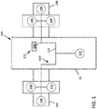
- An aircraft 100 includes a fuselage 102 defining a cabin sized to carry a pilot and one or more passengers.
- the aircraft 100 also includes a first wing 104 and a second wing 106 that each carry one or more propeller arrangements 108 or other propulsion components.
- three propeller arrangements 108 are disposed at each wing 104, 106.
- each wing 104, 106 may carry any desired number or propulsion components.
- each propeller arrangement 108 includes a motor and an inverter to operate the propeller arrangement 108.
- the aircraft 100 includes a power system 110 including at least one battery 112 that powers the propeller arrangements 108 via a power bus 114.
- the propeller arrangements 108 are powered by a main battery 112 carried by the fuselage 102.
- the propeller arrangements 108 may be powered by one or more batteries 112 carried by the wings 104, 106.
- the power system 110 also provides electric power to other components of the aircraft such as the flight management system, the control display unit, and/or lighting.
- the power system 110 also provides electric power to one or more components 116 of a thermal management system 120 used to cool the battery 112 and/or other components such as the propeller arrangement 108.
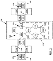
- FIG. 2 illustrates an example thermal management system 120 including one or more cooling circuits 122, 124, 126, 128 that cool various components of the aircraft.
- the thermal management system 120 includes a battery cooling circuit 122 configured to cool one or more batteries 112 of the power system 110, a refrigeration circuit 124 configured to cool one or more of the cooling circuits 122, 126, 128, a first motor/inverter cooling circuit 126 configured to cool one or more of the propeller arrangements 108 at the first wing 104, and a second motor/inverter cooling circuit 128 configured to cool one or more of the propeller arrangements 108 at the second wing 106.
- each propeller arrangement 108 may have a corresponding motor/inverter cooling circuit 126.
- each propeller arrangement 108 may have a respective battery 112 and battery cooling circuit 122.
- the battery cooling circuit 122 includes a tank 130 configured to hold coolant (e.g., water), a pump 132 configured to draw the coolant from the tank 130, and a conduit 134 along which the coolant flows through the battery cooling circuit 122.
- the conduit 134 is directed from the pump 132 towards the battery 112. After absorbing heat from the battery 112, the coolant is directed to a chiller 136 at which heat from the coolant is absorbed by refrigerant passing through the refrigeration circuit 124. The cooled coolant then passes back to the tank 130.
- the refrigeration circuit 124 includes a conduit 138 through which the refrigerant (e.g., glycol) is carried through the refrigeration circuit 124.
- the refrigeration circuit 124 also includes a compressor 140 configured to draw the refrigerant along the conduit 138 and to pressurize (e.g., vaporize) the refrigerant; a condenser 142 at which at least some heat is removed from the pressurized refrigerant; and an expansion valve 144 creates a pressure drop so that low temperature, low pressure refrigerant is then conveyed to the chiller 136 at which the refrigerant absorbs heat from the coolant of the battery cooling circuit 122.
- a compressor 140 configured to draw the refrigerant along the conduit 138 and to pressurize (e.g., vaporize) the refrigerant; a condenser 142 at which at least some heat is removed from the pressurized refrigerant; and an expansion valve 144 creates a pressure drop so that low temperature, low pressure refrigerant
- Each of the motor/inverters cooling circuits 126, 128 includes a conduit 146 through which coolant flows through the circuit.
- Each of the motor/inverter cooling circuits 126, 128 also includes a tank 148, a pump arrangement 150 of one or more pumps to draw coolant from the tank 148 and circulate the coolant through the conduit 146, and a radiator 152 exposed to ambient air outside the aircraft.
- the coolant passes from the pump arrangement 150 to a motor and/or an inverter of one or more of the propeller arrangements 108 at which heat is absorbed by the coolant.
- the heated coolant is air cooled at the radiator 152 before returning to the tank 148.
- each of the coolant circuits 122, 126, 128 operates independently.
- one or more of the coolant circuits 122, 126, 128 may be fluidly coupled.
- the tanks 148, 130 of each coolant circuit 122, 126, 128 may be fluidly coupled together.
- two of more of the coolant circuits 122, 126, 128 may be selectively fluidly coupled together using directional control valves operated by an electronic controller.
- two or more of the coolant circuits 122, 126, 128 may be fluidly coupled during a failure of one or more components of one of the coolant circuits or during a period where one or more components of the power system 110 require extra cooling.
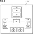
- FIG. 3 illustrates a system control schema 160 by which the components of the power system 110 and the thermal management system 120 are operated.
- the control schema 160 includes one or more electronic controllers that each include a memory and processor configured to store and implement instructions for operating the components.
- the control schema 160 includes a system controller 162 implementing a flight management system.
- the system controller 162 includes a user interface 164 (e.g., a graphic user interface) at which commands can be input by a pilot of the aircraft 100.
- the system controller 162 also may include an interface 166 by which the system controller 162 communicates with a TMS controller 168 of the thermal management system 120. In other examples, the system controller 162 may operate the thermal management system 120 directly.
- the TMS controller 168 is configured to operate components of the thermal management system 120.
- the TMS controller 168 controls the operation of the pump 132 (e.g., controls the speed and/or volume of the coolant through the pump) of the battery cooling circuit 122, the compressor 140 (e.g., controls the speed and/or volume of the refrigerant through the compressor) of the refrigerant circuit 124, and the pump arrangements 150 (e.g., controls the speed and/or volume of the coolant through the pump arrangement) of the motor/inverter circuits 126, 128.
- the TMS controller 168 controls separate pumps 150A-150N for each propeller arrangement 108.
- FIG. 4 illustrates an example TMS controller 168 suitable for use in operating the thermal management system 110.
- the TMS controller 168 includes one or more electronic memories 172 configured to store instructions 174 for operating the various components of the thermal management system 110.
- the TMS controller 168 also includes one or more processors 170 configured to implement the instructions stored in the memory 172.
- the TMS controller 168 includes interfaces to communicate with the various components, such as a compressor interface 176 by which the processor 170 controls the compressor 140 of the refrigeration circuit 124 and one or more pump interfaces 178 by which the processor 170 controls the pumps 150 of the motor/inverter cooling circuits 126, 128 and/or the pump 132 of the battery cooling circuit 122.
- the TMS controller 168 also includes a temperature sensor arrangement 180 (or an interface for a temperature sensor arrangement) including one or more temperature sensors disposed at components of the power system 110.
- a temperature sensor may be disposed at the battery 112, at one or more of the motors and/or one or more of the inverters of the propeller arrangements 108, at the chiller 136, or at any other desired component.
- the temperature sensor arrangement 180 may determine a temperature of a component based on other sensed data (e.g., pressure, movement, etc.). Temperature data 182 obtained by the temperature sensor arrangement 180 is communicated to the processor 170 and/or is stored in the memory 172.
- a first threshold 184 may indicate an upper temperature limit for the battery 112 and a second threshold 186 may indicate a lower temperature limit for the battery 112.
- the first and second thresholds 184, 186 may indicate temperatures at which action must be taken to cool or warm the battery 112 before an upper or lower temperature threshold of the battery 112 is reached.
- Other thresholds that can be stored include a maximum temperature limit for the motor of a propeller arrangement 108, a maximum temperature limit for the inverter of a propeller arrangement 108, a maximum temperature limit for the chiller 136, and other such boundaries.
- the TMS controller 168 includes a system interface 188 by which the TMS controller 168 communicates with the system controller 162. In certain implementations, the TMS controller 168 monitors commands input by the pilot using the system interface 188. In certain implementations, the TMS controller 168 monitors commands obtained from a flight plan 190 entered into the system controller 162 before or during a flight.
- the flight plan 190 includes various commands MC 1 -MC N (e.g., take-off commands, landing commands, hovering commands, turning commands, etc.) for controlling the propeller arrangements 108.
- the flight plan 190 also includes trigger events Trig 1 -Trig N (e.g., positioning along the flight path such as GPS coordinates, timing, etc.) at which a corresponding one or more of the commands MC 1 -MC N is executed.
- the flight plan 190 can be stored in the memory 172 of the TMS controller 168.
- FIGS. 5 and 6 illustrate processes by which the TMS controller 168 can operate the thermal management system 120.
- FIG. 5 shows a first process 200 by which the TMS controller 168 operates the thermal management system 120 based on monitored commands received by the pilot and the temperature data 182.
- FIG. 6 shows a second process 220 by which the TMS controller 168 operates the thermal management system 120 based on the flight plan 190 and/or the temperature data 182.
- the TMS controller 168 implements both processes 200, 220.
- the TMS controller 168 may implement the second process 220 to anticipate thermal cycling based on known upcoming commands based on the flight plan 190 while also using the first process 200 to react quickly to unexpected commands input by the pilot.
- the first process 200 begins at a first operation 202 by operating the thermal management system 120 at a normal level of operation for each component.
- the pump 132, 150 of each coolant circuit 122, 126, 128 circulates a predetermined volume of coolant at a predetermined rate selected to cool the corresponding power system components based on a standard operating temperature of the components.
- the TMS controller 168 monitors commands (e.g., maneuver commands) input by the pilot at a second operation 204.
- the TMS controller 168 determines whether the commands indicate a high power event (e.g., take-off, landing, hovering, turning) is starting. If the TMS controller 168 determines at module 206 that the command does not indicate that a high power event is starting, then the TMS controller 168 continues to monitor commands at the second operation 204. However, if the TMS controller 168 determines at the module 206 that a high power event is starting, then the TMS controller 168 determines which components of the power system 110 will be affected by the high power event (e.g., are likely to heat up) at a third operation 208.
- commands e.g., maneuver commands
- the TMS controller 168 determines whether the commands indicate a high power event (e.g., take-off, landing, hovering, turning) is starting. If the TMS controller 168 determines at module 206 that the command does not indicate
- the TMS controller 168 increases cooling at the determined components. For example, if the TMS controller 168 determines that a turn event is starting, then the TMS controller 168 may increase a flow rate of a pump 150 of the cooling circuit 126, 128 of one of the wings 104, 106 to provide enhanced cooling at the motor and/or inverter of the relevant propeller arrangements 108. In certain examples, the TMS controller 168 may determine at the third operation 208 that the battery 112 is likely to experience an enhanced power draw during the high power event and may provide enhanced cooling (may increase the flow rate of pump 132) to the battery 112 at the fourth operation 210.
- the TMS controller 168 also may enhance cooling by increasing a flow rate of the compressor 140 to increase the amount of refrigerant being provided to the chiller 136 to cool the coolant of the battery cooling circuit 122.
- the TMS controller 168 may fluidly couple together the coolant of one or more of the cooling circuits 122, 126, 128. Accordingly, the enhanced cooling provided to the battery cooling circuit 122 by the refrigeration circuit 124 may be distributed to the motor/inverter cooling circuits 126, 128.
- the coolant of the battery cooling circuit 122 could be further cooled by passage by the radiators 152 of the motor/inverter cooling circuits 126, 128.
- the TMS controller 168 may determine at the third operation 208 one or more components at which a temperature is expected to decrease during a high power event. For example, if the high power event is a turn, then the propeller arrangements 108 on one of the wings 104, 106 may draw more power than during normal operation and the propeller arrangements 108 on the other of the wings 104, 106 may draw less power than during normal operation. In such situations, at the fourth operation 210, the TMS controller 168 may temporarily reduce the amount of coolant supplied to the propeller arrangement 108 or other component expected to generate less heat. In certain examples, the TMS controller 168 may direct coolant that otherwise would have been supplied to the component expected to generate less heat to the component expected to generate more heat instead.
- the TMS controller 168 also monitors temperature data obtained by the temperature sensor arrangement 180 to further adjust cooling provided to the various components. For example, the TMS controller 168 may continue to increase a flow rate of the coolant and/or a flow rate of the refrigerant if the temperature of one or more of the identified components is determined at module 212 to increase beyond a first threshold T1 (e.g., first threshold 184). Likewise, the TMS controller 168 may decrease the flow rate of the coolant and/or the flow rate of the refrigerant at a fifth operation 216 if the temperature of one or more of the identified components is determined at module 214 to decrease beyond a second threshold T2 (e.g., second 186). When the TMS controller 168 determines at module 218 that the high power event is ending (e.g., receives a command to stop turning), then the TMS controller 168 returns the thermal management system to operating at a normal cooling state.
- a first threshold T1 e.g., first threshold 184
- the second process 220 begins at a first operation 222 at which the TMS controller 168 and/or the system controller 162 receive a flight plan 190 for the aircraft 100.
- all or portions of the flight plan 190 is stored in the memory 172 of the TMS controller 168.
- the flight plan 190 is stored in the memory of the system controller 162.
- the planned high powered events included in the flight plan 190 are identified.
- the high powered events may include take-off, hovering, turning, and landing. Triggers for the high powered events also are identified.
- the triggers may include a maneuver command entered by the pilot.
- the triggers may include a geographic location of the aircraft (i.e., position along a planned flight path), a time, etc.).
- the TMS controller 168 operates the thermal management system 120 at a normal level of operation for each component.
- the pump 132, 150 of each coolant circuit 122, 126, 128 circulates a predetermined volume of coolant at a predetermined rate selected to cool the corresponding power system components based on a standard operating temperature of the components.
- the TMS controller 168 monitors a status of the flight plan 190 at a fourth operation 228.
- the TMS controller 168 determines at module 230 when an identified high power event is imminent (e.g., based on the previously executed commands and/or based on the position of the aircraft along the planned flight path).
- the TMS controller 168 determines a high power event is imminent, the TMS controller 168 identifies one or more components that would be affected by the high power event and determines a likely temperature rise or drop for each component at a fifth operation 232.
- the flight plan 190 may indicate that a propeller arrangement 108 is intended to operate at a predetermined power level for a predetermined period of time.
- the amount of heat generated by the propeller arrangement 108 operating at the predetermined power level for the predetermined period of time can be calculated based on known thermal principles.
- the TMS controller 168 also may calculate how much power may be required from the battery 112 to operate the propeller arrangement 108 at the predetermined power level for a predetermined period of time and, therefore, calculate a resulting temperature increase for the battery 112.
- the TMS controller 168 adjusts the level of cooling provided to each component based on the calculations of the fifth operation 232. For example, the TMS controller 168 may increase a coolant rate of an identified motor/inverter cooling circuit 126, 128 by a calculated amount. In certain implementations, the TMS controller 168 increases the coolant rate before a temperature of the identified motor/inverter has begun to increase. In certain implementations, the TMS controller 168 may increase the coolant rate before the maneuver command of the high power event is implemented by the aircraft 100 (e.g., before the propeller arrangement 108 begins executing the maneuver).
- the TMS controller 168 may increase the coolant rate a predetermined period of time (e.g., one or more seconds, one or more minutes, etc.) before the maneuver command of the flight plan 190 is intended to be executed (e.g., before the aircraft 100 reaches the relevant geographical location at which the maneuver command is to be executed).
- the TMS controller 168 may decrease a coolant rate of the motor/inverter cooling circuit 126, 128 of a propeller arrangement 108 expected to cool down (or to not heat up) during the high power event.
- the TMS controller 168 also may increase a compressor speed to increase a flow rate of the refrigerant through the refrigeration circuit 124 if needed based on the calculations.
- the TMS controller 168 determines at module 236 whether the high power event is ending. For example, the TMS controller 168 may determine that the aircraft 100 has reached a particular geographic location (e.g., has finished turning to stay on the flight path) or that a subsequent maneuver command is being executed. The TMS controller 168 may continue adjusting the cooling of the various components until the high power event is over. Once over, the TMS controller 168 may return to normal operation. Alternatively, the TMs controller 168 may proceed to a module 238 at which the TMS controller 168 determines whether the temperature of the various components obtained by the temperature sensor arrangement 180 has returned to normal (e.g., are within predetermined tolerances). In such examples, the TMS controller 168 returns to normal operation only if the relevant components have cooled down enough for normal thermal cooling to be sufficient. Otherwise, the TMs controller 168 continues to adjust the thermal cooling of the relevant components until temperatures are within tolerances.
- the TMS controller 168 may begin cooling of one or more components (e.g., increase relevant coolant pump flow rate) based on an expected flight plan maneuver that has not yet been implemented, but not fully increase the cooling to calculated levels until the command has been implemented.
- the TMS controller 168 may increase pump flow by a first amount prior to execution of the maneuver and increase by a second amount during or after execution of the maneuver.
- the TMS controller 168 may increase a coolant pump flow prior to execution of the maneuver and increase a refrigerant flow during or after execution of the maneuver.
- the TMS controller 168 may increase a refrigerant flow prior to execution of the maneuver and increase a coolant pump flow during or after execution of the maneuver. Accordingly, the thermal management system 120 still takes proactive action to mitigate the temperature spike for the relevant components while also mitigating unnecessary stress on the components of the thermal management system.
Landscapes
- Engineering & Computer Science (AREA)
- Chemical & Material Sciences (AREA)
- Aviation & Aerospace Engineering (AREA)
- Manufacturing & Machinery (AREA)
- General Chemical & Material Sciences (AREA)
- Electrochemistry (AREA)
- Chemical Kinetics & Catalysis (AREA)
- Mechanical Engineering (AREA)
- Automation & Control Theory (AREA)
- General Physics & Mathematics (AREA)
- Physics & Mathematics (AREA)
- Combustion & Propulsion (AREA)
- Life Sciences & Earth Sciences (AREA)
- Sustainable Development (AREA)
- Sustainable Energy (AREA)
- Power Engineering (AREA)
- Transportation (AREA)
- Cooling Or The Like Of Electrical Apparatus (AREA)
- Electric Propulsion And Braking For Vehicles (AREA)
Abstract
Description
- Various components within an aircraft require thermal management to operate. For example, a propeller motor and a battery powering the propeller motor both generate heat during operation and can overheat (surpass an upper temperature limit) if left uncooled. Certain components, such as the battery, also may have a lower temperature limit to operate properly. Accordingly, the aircraft is equipped with a thermal management system including cooling circuits for these components.
- The thermal cycling of these components does not remain constant during a flight. Rather, each component may have a normal operating temperature based on normal power consumption during the flight and peak operating temperatures resulting from specific events occurring during the flight. For example, the heat of a motor and/or inverter of a propeller arrangement of the aircraft may increase during take off, landing, hovering, or turning of the aircraft compared to the temperature during cruising. The heat of the battery also may cycle based on how much power is drawn by the propeller arrangements or other components during the flight. Accordingly, the thermal management system is typically configured to provide sufficient cooling for the expected elevated temperatures.
- Some aspects of the disclosure are directed to a thermal management system configured to provide proactive cooling to one or more components of a power system to mitigate the temperature cycle of the component during a high power event (e.g., take off, landing, hovering, turning, etc.).
- By proactively cooling the components, the peak operating temperature of the component may be reduced. Accordingly, the maximum output of the
thermal management system 120 required to combat these peak operating temperatures also may be mitigated, which allows for smaller/lighter components of thethermal management system 120. For example, the flow rate of the coolant needing to pass over a component during a high power event may be reduced, which allows for the use of a smaller pump arrangement. The amount of heat needing to be removed from the coolant during a high power event also may be reduced, which allows for the use of a smaller radiator, a smaller chiller, a smaller condenser, and/or a reduced amount of coolant carried by the aircraft. - In certain implementations, the thermal management system provides cooling to a component before the temperature of the component has begun to rise based on an expectation of a temperature rise. In some implementations, the expectation that the temperature will rise is based on a maneuver command (e.g., take-off, land, hover, turn) sent to the flight management system by the pilot. In other implementations, the expectation that the temperature will rise is based on a maneuver command included in a flight plan for the aircraft. In some examples, the thermal management system increases cooling of a component expected to be affected by the high power event even before the command from the flight plan is implemented. In other examples, the thermal management system increases cooling of a component expected to be affected by the high power even after the command is implemented, but before the temperature of the component has exceeded an upper boundary threshold.
- A variety of additional inventive aspects will be set forth in the description that follows. The inventive aspects can relate to individual features and to combinations of features. It is to be understood that both the forgoing general description and the following detailed description are exemplary and explanatory only and are not restrictive of the broad inventive concepts upon which the embodiments disclosed herein are based.
- The accompanying drawings, which are incorporated in and constitute a part of the description, illustrate several aspects of the present disclosure. A brief description of the drawings is as follows:
-
FIG. 1 is a schematic diagram of an example aircraft power system; -
FIG. 2 is a schematic diagram of a thermal management system for use in cooling the power system, the thermal management system including one or more cooling circuits for the propellers in each wing, a battery cooling circuit, and a refrigeration circuit; -
FIG. 3 illustrates an electronic controller schema for the thermal management system; -
FIG. 4 is a schematic diagram of a thermal management system controller suitable for use with the thermal management system ofFIG. 2 in the electronic controller schema ofFIG. 3 ; -
FIG. 5 is a flowchart illustrating a first thermal management system control process; and -
FIG. 6 is a flowchart illustrating a second thermal management system control process. - Reference will now be made in detail to exemplary aspects of the present disclosure that are illustrated in the accompanying drawings. Wherever possible, the same reference numbers will be used throughout the drawings to refer to the same or like parts.
- An
aircraft 100 includes afuselage 102 defining a cabin sized to carry a pilot and one or more passengers. Theaircraft 100 also includes afirst wing 104 and asecond wing 106 that each carry one ormore propeller arrangements 108 or other propulsion components. In the example shown, threepropeller arrangements 108 are disposed at eachwing wing propeller arrangement 108 includes a motor and an inverter to operate thepropeller arrangement 108. - The
aircraft 100 includes apower system 110 including at least onebattery 112 that powers thepropeller arrangements 108 via apower bus 114. In the example shown, thepropeller arrangements 108 are powered by amain battery 112 carried by thefuselage 102. In other examples, thepropeller arrangements 108 may be powered by one ormore batteries 112 carried by thewings power system 110 also provides electric power to other components of the aircraft such as the flight management system, the control display unit, and/or lighting. In certain implementations, thepower system 110 also provides electric power to one ormore components 116 of athermal management system 120 used to cool thebattery 112 and/or other components such as thepropeller arrangement 108. -
FIG. 2 illustrates an examplethermal management system 120 including one ormore cooling circuits thermal management system 120 includes abattery cooling circuit 122 configured to cool one ormore batteries 112 of thepower system 110, arefrigeration circuit 124 configured to cool one or more of thecooling circuits inverter cooling circuit 126 configured to cool one or more of thepropeller arrangements 108 at thefirst wing 104, and a second motor/inverter cooling circuit 128 configured to cool one or more of thepropeller arrangements 108 at thesecond wing 106. In other examples, eachpropeller arrangement 108 may have a corresponding motor/inverter cooling circuit 126. In other examples, eachpropeller arrangement 108 may have arespective battery 112 andbattery cooling circuit 122. - The
battery cooling circuit 122 includes atank 130 configured to hold coolant (e.g., water), apump 132 configured to draw the coolant from thetank 130, and aconduit 134 along which the coolant flows through thebattery cooling circuit 122. Theconduit 134 is directed from thepump 132 towards thebattery 112. After absorbing heat from thebattery 112, the coolant is directed to achiller 136 at which heat from the coolant is absorbed by refrigerant passing through therefrigeration circuit 124. The cooled coolant then passes back to thetank 130. - The
refrigeration circuit 124 includes aconduit 138 through which the refrigerant (e.g., glycol) is carried through therefrigeration circuit 124. Therefrigeration circuit 124 also includes acompressor 140 configured to draw the refrigerant along theconduit 138 and to pressurize (e.g., vaporize) the refrigerant; acondenser 142 at which at least some heat is removed from the pressurized refrigerant; and anexpansion valve 144 creates a pressure drop so that low temperature, low pressure refrigerant is then conveyed to thechiller 136 at which the refrigerant absorbs heat from the coolant of thebattery cooling circuit 122. - Each of the motor/
inverters cooling circuits conduit 146 through which coolant flows through the circuit. Each of the motor/inverter cooling circuits tank 148, apump arrangement 150 of one or more pumps to draw coolant from thetank 148 and circulate the coolant through theconduit 146, and aradiator 152 exposed to ambient air outside the aircraft. The coolant passes from thepump arrangement 150 to a motor and/or an inverter of one or more of thepropeller arrangements 108 at which heat is absorbed by the coolant. The heated coolant is air cooled at theradiator 152 before returning to thetank 148. - In some implementations, each of the
coolant circuits coolant circuits tanks coolant circuit coolant circuits coolant circuits power system 110 require extra cooling. -
FIG. 3 illustrates asystem control schema 160 by which the components of thepower system 110 and thethermal management system 120 are operated. Thecontrol schema 160 includes one or more electronic controllers that each include a memory and processor configured to store and implement instructions for operating the components. In certain examples, thecontrol schema 160 includes asystem controller 162 implementing a flight management system. Thesystem controller 162 includes a user interface 164 (e.g., a graphic user interface) at which commands can be input by a pilot of theaircraft 100. Thesystem controller 162 also may include aninterface 166 by which thesystem controller 162 communicates with aTMS controller 168 of thethermal management system 120. In other examples, thesystem controller 162 may operate thethermal management system 120 directly. - The
TMS controller 168 is configured to operate components of thethermal management system 120. For example, theTMS controller 168 controls the operation of the pump 132 (e.g., controls the speed and/or volume of the coolant through the pump) of thebattery cooling circuit 122, the compressor 140 (e.g., controls the speed and/or volume of the refrigerant through the compressor) of therefrigerant circuit 124, and the pump arrangements 150 (e.g., controls the speed and/or volume of the coolant through the pump arrangement) of the motor/inverter circuits TMS controller 168 controlsseparate pumps 150A-150N for eachpropeller arrangement 108. -
FIG. 4 illustrates anexample TMS controller 168 suitable for use in operating thethermal management system 110. TheTMS controller 168 includes one or moreelectronic memories 172 configured to storeinstructions 174 for operating the various components of thethermal management system 110. TheTMS controller 168 also includes one ormore processors 170 configured to implement the instructions stored in thememory 172. TheTMS controller 168 includes interfaces to communicate with the various components, such as acompressor interface 176 by which theprocessor 170 controls thecompressor 140 of therefrigeration circuit 124 and one ormore pump interfaces 178 by which theprocessor 170 controls thepumps 150 of the motor/inverter cooling circuits pump 132 of thebattery cooling circuit 122. - The
TMS controller 168 also includes a temperature sensor arrangement 180 (or an interface for a temperature sensor arrangement) including one or more temperature sensors disposed at components of thepower system 110. For example, a temperature sensor may be disposed at thebattery 112, at one or more of the motors and/or one or more of the inverters of thepropeller arrangements 108, at thechiller 136, or at any other desired component. In other implementations, thetemperature sensor arrangement 180 may determine a temperature of a component based on other sensed data (e.g., pressure, movement, etc.).Temperature data 182 obtained by thetemperature sensor arrangement 180 is communicated to theprocessor 170 and/or is stored in thememory 172. - Various temperature thresholds also may be stored in the
memory 172 of theTMS controller 168. For example, afirst threshold 184 may indicate an upper temperature limit for thebattery 112 and asecond threshold 186 may indicate a lower temperature limit for thebattery 112. In other examples, the first andsecond thresholds battery 112 before an upper or lower temperature threshold of thebattery 112 is reached. Other thresholds that can be stored include a maximum temperature limit for the motor of apropeller arrangement 108, a maximum temperature limit for the inverter of apropeller arrangement 108, a maximum temperature limit for thechiller 136, and other such boundaries. - In certain implementations, the
TMS controller 168 includes asystem interface 188 by which theTMS controller 168 communicates with thesystem controller 162. In certain implementations, theTMS controller 168 monitors commands input by the pilot using thesystem interface 188. In certain implementations, theTMS controller 168 monitors commands obtained from aflight plan 190 entered into thesystem controller 162 before or during a flight. Theflight plan 190 includes various commands MC1-MCN (e.g., take-off commands, landing commands, hovering commands, turning commands, etc.) for controlling thepropeller arrangements 108. In certain examples, theflight plan 190 also includes trigger events Trig1-TrigN (e.g., positioning along the flight path such as GPS coordinates, timing, etc.) at which a corresponding one or more of the commands MC1-MCN is executed. In certain examples, theflight plan 190 can be stored in thememory 172 of theTMS controller 168. -
FIGS. 5 and6 illustrate processes by which theTMS controller 168 can operate thethermal management system 120.FIG. 5 shows afirst process 200 by which theTMS controller 168 operates thethermal management system 120 based on monitored commands received by the pilot and thetemperature data 182.FIG. 6 shows asecond process 220 by which theTMS controller 168 operates thethermal management system 120 based on theflight plan 190 and/or thetemperature data 182. In certain implementations, theTMS controller 168 implements bothprocesses TMS controller 168 may implement thesecond process 220 to anticipate thermal cycling based on known upcoming commands based on theflight plan 190 while also using thefirst process 200 to react quickly to unexpected commands input by the pilot. - As shown in
FIG. 5 , thefirst process 200 begins at afirst operation 202 by operating thethermal management system 120 at a normal level of operation for each component. For example, thepump coolant circuit - The
TMS controller 168 monitors commands (e.g., maneuver commands) input by the pilot at asecond operation 204. TheTMS controller 168 determines whether the commands indicate a high power event (e.g., take-off, landing, hovering, turning) is starting. If theTMS controller 168 determines atmodule 206 that the command does not indicate that a high power event is starting, then theTMS controller 168 continues to monitor commands at thesecond operation 204. However, if theTMS controller 168 determines at themodule 206 that a high power event is starting, then theTMS controller 168 determines which components of thepower system 110 will be affected by the high power event (e.g., are likely to heat up) at athird operation 208. - At a
fourth operation 210, theTMS controller 168 increases cooling at the determined components. For example, if theTMS controller 168 determines that a turn event is starting, then theTMS controller 168 may increase a flow rate of apump 150 of thecooling circuit wings relevant propeller arrangements 108. In certain examples, theTMS controller 168 may determine at thethird operation 208 that thebattery 112 is likely to experience an enhanced power draw during the high power event and may provide enhanced cooling (may increase the flow rate of pump 132) to thebattery 112 at thefourth operation 210. - In certain implementations, the
TMS controller 168 also may enhance cooling by increasing a flow rate of thecompressor 140 to increase the amount of refrigerant being provided to thechiller 136 to cool the coolant of thebattery cooling circuit 122. In certain implementations, theTMS controller 168 may fluidly couple together the coolant of one or more of the coolingcircuits battery cooling circuit 122 by therefrigeration circuit 124 may be distributed to the motor/inverter cooling circuits battery cooling circuit 122 could be further cooled by passage by theradiators 152 of the motor/inverter cooling circuits - In certain examples, the
TMS controller 168 may determine at thethird operation 208 one or more components at which a temperature is expected to decrease during a high power event. For example, if the high power event is a turn, then thepropeller arrangements 108 on one of thewings propeller arrangements 108 on the other of thewings fourth operation 210, theTMS controller 168 may temporarily reduce the amount of coolant supplied to thepropeller arrangement 108 or other component expected to generate less heat. In certain examples, theTMS controller 168 may direct coolant that otherwise would have been supplied to the component expected to generate less heat to the component expected to generate more heat instead. - In certain implementations, the
TMS controller 168 also monitors temperature data obtained by thetemperature sensor arrangement 180 to further adjust cooling provided to the various components. For example, theTMS controller 168 may continue to increase a flow rate of the coolant and/or a flow rate of the refrigerant if the temperature of one or more of the identified components is determined atmodule 212 to increase beyond a first threshold T1 (e.g., first threshold 184). Likewise, theTMS controller 168 may decrease the flow rate of the coolant and/or the flow rate of the refrigerant at afifth operation 216 if the temperature of one or more of the identified components is determined atmodule 214 to decrease beyond a second threshold T2 (e.g., second 186). When theTMS controller 168 determines atmodule 218 that the high power event is ending (e.g., receives a command to stop turning), then theTMS controller 168 returns the thermal management system to operating at a normal cooling state. - As shown in
FIG. 6 , thesecond process 220 begins at afirst operation 222 at which theTMS controller 168 and/or thesystem controller 162 receive aflight plan 190 for theaircraft 100. In some examples, all or portions of theflight plan 190 is stored in thememory 172 of theTMS controller 168. In other examples, theflight plan 190 is stored in the memory of thesystem controller 162. At asecond operation 224, the planned high powered events included in theflight plan 190 are identified. For example, the high powered events may include take-off, hovering, turning, and landing. Triggers for the high powered events also are identified. In some examples, the triggers may include a maneuver command entered by the pilot. In other examples, the triggers may include a geographic location of the aircraft (i.e., position along a planned flight path), a time, etc.). - At a
third operation 226, theTMS controller 168 operates thethermal management system 120 at a normal level of operation for each component. For example, thepump coolant circuit TMS controller 168 monitors a status of theflight plan 190 at afourth operation 228. For example, theTMS controller 168 determines atmodule 230 when an identified high power event is imminent (e.g., based on the previously executed commands and/or based on the position of the aircraft along the planned flight path). - When the
TMS controller 168 determines a high power event is imminent, theTMS controller 168 identifies one or more components that would be affected by the high power event and determines a likely temperature rise or drop for each component at afifth operation 232. For example, theflight plan 190 may indicate that apropeller arrangement 108 is intended to operate at a predetermined power level for a predetermined period of time. The amount of heat generated by thepropeller arrangement 108 operating at the predetermined power level for the predetermined period of time can be calculated based on known thermal principles. TheTMS controller 168 also may calculate how much power may be required from thebattery 112 to operate thepropeller arrangement 108 at the predetermined power level for a predetermined period of time and, therefore, calculate a resulting temperature increase for thebattery 112. - At a
sixth operation 234, theTMS controller 168 adjusts the level of cooling provided to each component based on the calculations of thefifth operation 232. For example, theTMS controller 168 may increase a coolant rate of an identified motor/inverter cooling circuit TMS controller 168 increases the coolant rate before a temperature of the identified motor/inverter has begun to increase. In certain implementations, theTMS controller 168 may increase the coolant rate before the maneuver command of the high power event is implemented by the aircraft 100 (e.g., before thepropeller arrangement 108 begins executing the maneuver). In certain implementations, theTMS controller 168 may increase the coolant rate a predetermined period of time (e.g., one or more seconds, one or more minutes, etc.) before the maneuver command of theflight plan 190 is intended to be executed (e.g., before theaircraft 100 reaches the relevant geographical location at which the maneuver command is to be executed). In certain implementations, theTMS controller 168 may decrease a coolant rate of the motor/inverter cooling circuit propeller arrangement 108 expected to cool down (or to not heat up) during the high power event. TheTMS controller 168 also may increase a compressor speed to increase a flow rate of the refrigerant through therefrigeration circuit 124 if needed based on the calculations. - At
module 236, theTMS controller 168 determines atmodule 236 whether the high power event is ending. For example, theTMS controller 168 may determine that theaircraft 100 has reached a particular geographic location (e.g., has finished turning to stay on the flight path) or that a subsequent maneuver command is being executed. TheTMS controller 168 may continue adjusting the cooling of the various components until the high power event is over. Once over, theTMS controller 168 may return to normal operation. Alternatively, theTMs controller 168 may proceed to amodule 238 at which theTMS controller 168 determines whether the temperature of the various components obtained by thetemperature sensor arrangement 180 has returned to normal (e.g., are within predetermined tolerances). In such examples, theTMS controller 168 returns to normal operation only if the relevant components have cooled down enough for normal thermal cooling to be sufficient. Otherwise, theTMs controller 168 continues to adjust the thermal cooling of the relevant components until temperatures are within tolerances. - In certain implementations, the
TMS controller 168 may begin cooling of one or more components (e.g., increase relevant coolant pump flow rate) based on an expected flight plan maneuver that has not yet been implemented, but not fully increase the cooling to calculated levels until the command has been implemented. In an example, theTMS controller 168 may increase pump flow by a first amount prior to execution of the maneuver and increase by a second amount during or after execution of the maneuver. In another example, theTMS controller 168 may increase a coolant pump flow prior to execution of the maneuver and increase a refrigerant flow during or after execution of the maneuver. In another example, theTMS controller 168 may increase a refrigerant flow prior to execution of the maneuver and increase a coolant pump flow during or after execution of the maneuver. Accordingly, thethermal management system 120 still takes proactive action to mitigate the temperature spike for the relevant components while also mitigating unnecessary stress on the components of the thermal management system. -
- 1. A method of operating a thermal management system of an aircraft, the method comprising:
- operating a thermal management system in a normal operating mode;
- identifying an imminent temperature rise of a component of the aircraft; and
- increasing coolant flow to the component before a temperature of the component rises.
- 2. The method of
aspect 1, wherein identifying an imminent temperature rise of the component comprises:- monitoring maneuver commands provided to a system controller from a user interface, each maneuver command being associated with a power output level of one or more components of the aircraft;
- identifying the power output level of each maneuver command, wherein the imminent temperature rise is identified when the power output level is high; and
- identifying the one or more components associated with each maneuver command identified as being associated with a high power output level, wherein the component for which the imminent temperature rise is identified is one of the one or more identified components.
- 3. The method of
aspect 1, wherein identifying an imminent temperature rise of the component comprises:- receiving a flight plan including a plurality of maneuver commands;
- monitoring progress of a flight of the aircraft relative to the flight plan to determine upcoming maneuver commands;
- identifying the power output level of each upcoming maneuver command, wherein the imminent temperature rise is identified when the power output level is identified as high; and
- identifying the one or more components associated with each upcoming maneuver command identified as being associated with a high power output level, wherein the component for which the imminent temperature rise is identified is one of the one or more identified components.
- 4. The method of aspect 2 or aspect 3, wherein the coolant flow to the component is increased before the maneuver command is implemented by the system controller.
- 5. The method of aspect 3, wherein the coolant flow to the component is increased a predetermined period of time before the maneuver command is provided to the system controller.
- 6. The method of any of aspects 1-3, wherein increasing coolant flow to the component comprises identifying a pump associated with a cooling system for the component and increasing a flow rate of the identified pump.
- 7. The method of aspect 6, wherein increasing a flow rate of the identified pump comprises running the identified pump at a maximum speed.
- 8. The method of any of aspects 1-7, wherein the component is a battery.
- 9. The method of any of aspects 1-7, wherein the component is a motor arrangement.
- 10. The method of any of aspects 1-9, wherein the coolant flow is cooled using a refrigerant cycle, and wherein the method comprises increasing power supplied to a compressor of the refrigerant cycle after identifying an imminent temperature rise of a component of the aircraft.
- 11. The method of any of aspects 1-10, further comprising:
- monitoring a temperature of the component; and
- adjusting the coolant flow to the component based on the temperature of the component regardless of whether an imminent temperature rise has been identified.
- 12. The method of any of aspects 1-11, further comprising:
- determining a temperature of the component has dropped below a first threshold;
- determining that another temperature rise of the component is not imminent; and
- reducing the coolant flow to the component to a normal level.
- 13. The method of aspect 11, wherein adjusting the coolant flow to the component includes reducing the coolant flow if the temperature of the component drops below a second threshold.
- 14. The method of aspect 11, wherein adjusting the coolant flow to the component includes increasing the coolant flow if the temperature of the component rises above a third threshold.
- 15. The method of any of aspects 1-14, wherein the component is a first component; and wherein the method further comprises:
- identifying an imminent lower power consumption level of a second component; and
- reducing coolant flow to the second component.
- 16. The method of aspect 15, wherein reducing the coolant flow includes diverting at least a portion of the coolant flow to the first component.
- Having described the preferred aspects and implementations of the present disclosure, modifications and equivalents of the disclosed concepts may readily occur to one skilled in the art. However, it is intended that such modifications and equivalents be included within the scope of the claims which are appended hereto.
Claims (15)
- A method of operating a thermal management system of an aircraft, the method comprising:operating a thermal management system in a normal operating mode;identifying an imminent temperature rise of a component of the aircraft; andincreasing coolant flow to the component before a temperature of the component rises.
- The method of claim 1, wherein identifying an imminent temperature rise of the component comprises:monitoring maneuver commands provided to a system controller from a user interface, each maneuver command being associated with a power output level of one or more components of the aircraft;identifying the power output level of each maneuver command, wherein the imminent temperature rise is identified when the power output level is high; andidentifying the one or more components associated with each maneuver command identified as being associated with a high power output level, wherein the component for which the imminent temperature rise is identified is one of the one or more identified components.
- The method of claim 1, wherein identifying an imminent temperature rise of the component comprises:receiving a flight plan including a plurality of maneuver commands;monitoring progress of a flight of the aircraft relative to the flight plan to determine upcoming maneuver commands;identifying the power output level of each upcoming maneuver command, wherein the imminent temperature rise is identified when the power output level is identified as high; andidentifying the one or more components associated with each upcoming maneuver command identified as being associated with a high power output level, wherein the component for which the imminent temperature rise is identified is one of the one or more identified components.
- The method of claim 2 or claim 3, wherein the coolant flow to the component is increased before the maneuver command is implemented by the system controller.
- The method of claim 3, wherein the coolant flow to the component is increased a predetermined period of time before the maneuver command is provided to the system controller.
- The method of any of claims 1-3, wherein increasing coolant flow to the component comprises identifying a pump associated with a cooling system for the component and increasing a flow rate of the identified pump.
- The method of claim 6, wherein increasing a flow rate of the identified pump comprises running the identified pump at a maximum speed.
- The method of any of claims 1-7, wherein the component is a battery.
- The method of any of claims 1-7, wherein the component is a motor arrangement.
- The method of any of claims 1-9, wherein the coolant flow is cooled using a refrigerant cycle, and wherein the method comprises increasing power supplied to a compressor of the refrigerant cycle after identifying an imminent temperature rise of a component of the aircraft.
- The method of any of claims 1-10, further comprising:monitoring a temperature of the component; andadjusting the coolant flow to the component based on the temperature of the component regardless of whether an imminent temperature rise has been identified.
- The method of any of claims 1-11, further comprising:determining a temperature of the component has dropped below a first threshold;determining that another temperature rise of the component is not imminent; andreducing the coolant flow to the component to a normal level.
- The method of claim 11, wherein adjusting the coolant flow to the component includes reducing the coolant flow if the temperature of the component drops below a second threshold.
- The method of claim 11, wherein adjusting the coolant flow to the component includes increasing the coolant flow if the temperature of the component rises above a third threshold.
- The method of any of claims 1-14, wherein the component is a first component; and wherein the method further comprises:identifying an imminent lower power consumption level of a second component; andreducing coolant flow to the second component, wherein reducing the coolant flow includes diverting at least a portion of the coolant flow to the first component.
Applications Claiming Priority (1)
| Application Number | Priority Date | Filing Date | Title |
|---|---|---|---|
| IN202111039315 | 2021-08-31 |
Publications (2)
| Publication Number | Publication Date |
|---|---|
| EP4141609A1 true EP4141609A1 (en) | 2023-03-01 |
| EP4141609B1 EP4141609B1 (en) | 2026-02-11 |
Family
ID=83506093
Family Applications (1)
| Application Number | Title | Priority Date | Filing Date |
|---|---|---|---|
| EP22192958.1A Active EP4141609B1 (en) | 2021-08-31 | 2022-08-30 | Proactive thermal management system |
Country Status (3)
| Country | Link |
|---|---|
| US (1) | US12656793B2 (en) |
| EP (1) | EP4141609B1 (en) |
| ES (1) | ES3071033T3 (en) |
Families Citing this family (4)
| Publication number | Priority date | Publication date | Assignee | Title |
|---|---|---|---|---|
| EP4140896A1 (en) | 2021-08-31 | 2023-03-01 | Eaton Intelligent Power Limited | Thermal management system |
| EP4147977B1 (en) | 2021-09-14 | 2025-05-21 | Eaton Intelligent Power Limited | Thermal management system with dual condensers |
| US20250040107A1 (en) * | 2023-07-28 | 2025-01-30 | Honeywell International Inc. | Thermal management system for an electric vehicle |
| DE102025122365A1 (en) * | 2024-06-12 | 2025-12-18 | Eaton Intelligent Power Limited | ICE PROTECTION SYSTEM WITH WASTE HEAT RECOVERY |
Citations (1)
| Publication number | Priority date | Publication date | Assignee | Title |
|---|---|---|---|---|
| US20200339010A1 (en) * | 2019-04-23 | 2020-10-29 | Joby Aero, Inc. | Battery thermal management system and method |
Family Cites Families (40)
| Publication number | Priority date | Publication date | Assignee | Title |
|---|---|---|---|---|
| US8448460B2 (en) | 2008-06-23 | 2013-05-28 | GM Global Technology Operations LLC | Vehicular combination chiller bypass system and method |
| DE102008062176A1 (en) | 2008-12-13 | 2010-06-17 | Modine Manufacturing Co., Racine | Mechanism for tempering electrical elements in hybrid vehicle, has heat exchanger that is attached to refrigerant line which lies between condenser or gas radiator and expansion valve |
| DE102010042122B4 (en) | 2010-10-07 | 2019-02-28 | Audi Ag | Cooling device of a vehicle |
| US9669936B1 (en) | 2012-10-24 | 2017-06-06 | The Boeing Company | Aircraft air conditioning systems and methods |
| KR101628120B1 (en) | 2014-10-20 | 2016-06-08 | 현대자동차 주식회사 | Betterly cooling system for vehicle |
| US9780422B2 (en) | 2015-05-20 | 2017-10-03 | Ford Global Technologies, Llc | Cabin and battery cooling control for electrified vehicles |
| US10076944B2 (en) | 2016-01-29 | 2018-09-18 | Ford Global Technologies, Llc | Vehicle cabin air conditioning and battery cooling system |
| DE102016112095A1 (en) | 2016-07-01 | 2018-01-04 | Hanon Systems | A system for conditioning the air of a passenger compartment and for heat transfer with drive components of a motor vehicle and method for operating the system |
| US10644367B2 (en) | 2016-10-04 | 2020-05-05 | Ford Global Technologies, Llc | Electric vehicle battery cooling using excess cabin air conditioning capacity |
| DE102016219680A1 (en) | 2016-10-11 | 2018-04-12 | Siemens Aktiengesellschaft | Drive system for a vehicle with internal combustion engine and fuel tank |
| US11046448B2 (en) | 2016-12-20 | 2021-06-29 | Textron Innovations Inc. | Engine cooling systems for aircraft |
| US10513982B2 (en) | 2017-02-22 | 2019-12-24 | Textron Innovations Inc. | Rotorcraft having increased altitude density ceiling |
| KR102290819B1 (en) | 2017-02-27 | 2021-08-17 | 도시바 미쓰비시덴키 산교시스템 가부시키가이샤 | controller |
| JPWO2019039211A1 (en) | 2017-08-21 | 2020-10-01 | ソニー株式会社 | Motor device and motor-driven moving body |
| US10696412B2 (en) | 2017-09-29 | 2020-06-30 | The Boeing Company | Combined fluid ice protection and electronic cooling system |
| KR102391004B1 (en) | 2017-10-31 | 2022-04-27 | 현대자동차주식회사 | Method and system for controlling water pump |
| GB201718141D0 (en) | 2017-11-02 | 2017-12-20 | Rolls Royce Plc | Thermal management system |
| CN110286584A (en) * | 2018-03-19 | 2019-09-27 | 罗伯特·博世有限公司 | Motor vehicle cooling control system and method |
| JP7056335B2 (en) * | 2018-04-09 | 2022-04-19 | 株式会社デンソー | Travel control device |
| US11289756B2 (en) | 2018-05-18 | 2022-03-29 | The Johns Hopkins University | Active thermal management of battery cells via thermoelectrics |
| DE102018113687B4 (en) | 2018-06-08 | 2023-08-03 | Hanon Systems | Device and method for cooling battery cell modules |
| KR102575995B1 (en) | 2018-10-04 | 2023-09-08 | 한온시스템 주식회사 | Thermal management system |
| DE102019107191A1 (en) | 2019-03-20 | 2020-09-24 | Bayerische Motoren Werke Aktiengesellschaft | Heating system for an electric or hybrid vehicle, electric or hybrid vehicle, method for operating a heating system |
| US11466621B2 (en) | 2019-03-20 | 2022-10-11 | Raytheon Technologies Corporation | Adaptive thermal management system for aircraft fuel system |
| US11152653B2 (en) * | 2019-04-23 | 2021-10-19 | GM Global Technology Operations LLC | Battery thermal management |
| US11230384B2 (en) | 2019-04-23 | 2022-01-25 | Joby Aero, Inc. | Vehicle cabin thermal management system and method |
| AU2020283812A1 (en) | 2019-05-24 | 2021-12-16 | Alakai Technologies Corporation | Integrated multimode thermal energy transfer system, method and apparatus for clean fuel electric multirotor aircraft |
| US20210061477A1 (en) | 2019-08-30 | 2021-03-04 | Bell Textron Inc. | Cabin thermal management system |
| EP4054886A4 (en) * | 2019-11-07 | 2023-11-01 | Taiga Motors Inc. | THERMAL MANAGEMENT SYSTEM FOR AN ELECTRIC VEHICLE |
| CN114599584B (en) | 2019-11-12 | 2024-11-05 | 株式会社斯巴鲁 | Propulsion device, rotor anti-icing method and aircraft |
| CN110758056B (en) | 2019-11-25 | 2021-07-09 | 西安交通大学 | Vehicle thermal management system and method for hybrid electric vehicle |
| CN111591108A (en) | 2020-06-28 | 2020-08-28 | 南方英特空调有限公司 | Automobile heat pump heating system and method combining battery cooler and motor waste heat |
| CN213383775U (en) | 2020-08-17 | 2021-06-08 | 南方英特空调有限公司 | Heat pump system of automobile air conditioner |
| US11909019B2 (en) * | 2021-02-19 | 2024-02-20 | Transportation Ip Holdings, Llc | Battery management system |
| WO2022184325A1 (en) | 2021-03-05 | 2022-09-09 | Eaton Intelligent Power Limited | System and method for generating electrical energy from thermal waste energy and removing thermal waste energy in an aircraft |
| US12054266B2 (en) | 2021-03-29 | 2024-08-06 | Aurora Flight Sciences Corporation | Integrated electric nacelle system and method |
| EP4140896A1 (en) | 2021-08-31 | 2023-03-01 | Eaton Intelligent Power Limited | Thermal management system |
| EP4147977B1 (en) | 2021-09-14 | 2025-05-21 | Eaton Intelligent Power Limited | Thermal management system with dual condensers |
| US12285991B2 (en) | 2021-12-28 | 2025-04-29 | Nuro, Inc. | Thermal system for autonomous vehicle |
| US11827370B1 (en) | 2022-06-21 | 2023-11-28 | Pratt & Whitney Canada Corp. | Aircraft propulsion system with intermittent combustion engine and electric transmission system and method for operating the same |
-
2022
- 2022-08-30 ES ES22192958T patent/ES3071033T3/en active Active
- 2022-08-30 EP EP22192958.1A patent/EP4141609B1/en active Active
- 2022-08-30 US US17/898,965 patent/US12656793B2/en active Active
Patent Citations (1)
| Publication number | Priority date | Publication date | Assignee | Title |
|---|---|---|---|---|
| US20200339010A1 (en) * | 2019-04-23 | 2020-10-29 | Joby Aero, Inc. | Battery thermal management system and method |
Also Published As
| Publication number | Publication date |
|---|---|
| ES3071033T3 (en) | 2026-06-19 |
| EP4141609B1 (en) | 2026-02-11 |
| US12656793B2 (en) | 2026-06-16 |
| US20230067744A1 (en) | 2023-03-02 |
Similar Documents
| Publication | Publication Date | Title |
|---|---|---|
| EP4141609B1 (en) | Proactive thermal management system | |
| EP4140896A1 (en) | Thermal management system | |
| US11688903B2 (en) | Cooling modes to manage a high voltage battery for a vehicle | |
| US7975499B2 (en) | Aircraft supplemental cooling system | |
| US10340563B2 (en) | Traction battery cooling system with coolant proportional valve | |
| EP4147977B1 (en) | Thermal management system with dual condensers | |
| EP3173337B1 (en) | Aircraft air conditioning system with ambient air supply and method for operating such an aircraft air conditioning system | |
| CN113291128B (en) | Integrated power battery cooling system, cooling control method and electric automobile | |
| EP2527252A2 (en) | Adaptive power and thermal management system | |
| EP3279091B1 (en) | Aircraft electronics thermal regulation system | |
| US20220306300A1 (en) | Aircraft | |
| US20240300289A1 (en) | Thermal management system | |
| CN110816851A (en) | Helicopter environmental control integrated control system | |
| US20130239598A1 (en) | Aircraft environmental control system with conditioned heat sink | |
| EP4119444B1 (en) | Method for cooling an electrical aircraft propulsion system | |
| US10271465B2 (en) | System for cooling electric driving unit of aircraft | |
| US12491753B2 (en) | Thermal management system | |
| JP2771849B2 (en) | Cooling system using external surface cooler for avionics | |
| US20260097640A1 (en) | Anticipative cooling system for battery electric vehicle | |
| US12485726B2 (en) | Method for remediating loss of coolant flow or aerated coolant in thermal management of devices | |
| CN223956636U (en) | EVTOL battery thermal management system and aircraft | |
| CN215794520U (en) | Wide-flow pressure-adjustable general type avionics liquid cooling vehicle | |
| CN120127274A (en) | Thermal management system, temperature control system and thermal management method of eVTOL battery | |
| CN121993267A (en) | Aviation refrigeration power generation system, aircraft and control method | |
| US20250382062A1 (en) | Ice protection system using waste heat recovery |
Legal Events
| Date | Code | Title | Description |
|---|---|---|---|
| PUAI | Public reference made under article 153(3) epc to a published international application that has entered the european phase |
Free format text: ORIGINAL CODE: 0009012 |
|
| STAA | Information on the status of an ep patent application or granted ep patent |
Free format text: STATUS: THE APPLICATION HAS BEEN PUBLISHED |
|
| AK | Designated contracting states |
Kind code of ref document: A1 Designated state(s): AL AT BE BG CH CY CZ DE DK EE ES FI FR GB GR HR HU IE IS IT LI LT LU LV MC MK MT NL NO PL PT RO RS SE SI SK SM TR |
|
| P01 | Opt-out of the competence of the unified patent court (upc) registered |
Effective date: 20230521 |
|
| STAA | Information on the status of an ep patent application or granted ep patent |
Free format text: STATUS: REQUEST FOR EXAMINATION WAS MADE |
|
| 17P | Request for examination filed |
Effective date: 20230825 |
|
| RBV | Designated contracting states (corrected) |
Designated state(s): AL AT BE BG CH CY CZ DE DK EE ES FI FR GB GR HR HU IE IS IT LI LT LU LV MC MK MT NL NO PL PT RO RS SE SI SK SM TR |
|
| STAA | Information on the status of an ep patent application or granted ep patent |
Free format text: STATUS: EXAMINATION IS IN PROGRESS |
|
| 17Q | First examination report despatched |
Effective date: 20240117 |
|
| GRAP | Despatch of communication of intention to grant a patent |
Free format text: ORIGINAL CODE: EPIDOSNIGR1 |
|
| STAA | Information on the status of an ep patent application or granted ep patent |
Free format text: STATUS: GRANT OF PATENT IS INTENDED |
|
| INTG | Intention to grant announced |
Effective date: 20250916 |
|
| GRAS | Grant fee paid |
Free format text: ORIGINAL CODE: EPIDOSNIGR3 |
|
| GRAA | (expected) grant |
Free format text: ORIGINAL CODE: 0009210 |
|
| STAA | Information on the status of an ep patent application or granted ep patent |
Free format text: STATUS: THE PATENT HAS BEEN GRANTED |
|
| AK | Designated contracting states |
Kind code of ref document: B1 Designated state(s): AL AT BE BG CH CY CZ DE DK EE ES FI FR GB GR HR HU IE IS IT LI LT LU LV MC MK MT NL NO PL PT RO RS SE SI SK SM TR |
|
| REG | Reference to a national code |
Ref country code: CH Ref legal event code: F10 Free format text: ST27 STATUS EVENT CODE: U-0-0-F10-F00 (AS PROVIDED BY THE NATIONAL OFFICE) Effective date: 20260211 Ref country code: GB Ref legal event code: FG4D |
|
| REG | Reference to a national code |
Ref country code: DE Ref legal event code: R096 Ref document number: 602022030066 Country of ref document: DE |
|
| REG | Reference to a national code |
Ref country code: IE Ref legal event code: FG4D |
|
| REG | Reference to a national code |
Ref country code: NL Ref legal event code: MP Effective date: 20260211 |
|
| REG | Reference to a national code |
Ref country code: ES Ref legal event code: FG2A Ref document number: 3071033 Country of ref document: ES Kind code of ref document: T3 Effective date: 20260619 |
|
| PG25 | Lapsed in a contracting state [announced via postgrant information from national office to epo] |
Ref country code: RS Free format text: LAPSE BECAUSE OF FAILURE TO SUBMIT A TRANSLATION OF THE DESCRIPTION OR TO PAY THE FEE WITHIN THE PRESCRIBED TIME-LIMIT Effective date: 20260511 |
|
| PG25 | Lapsed in a contracting state [announced via postgrant information from national office to epo] |
Ref country code: PL Free format text: LAPSE BECAUSE OF FAILURE TO SUBMIT A TRANSLATION OF THE DESCRIPTION OR TO PAY THE FEE WITHIN THE PRESCRIBED TIME-LIMIT Effective date: 20260211 |
|
| PG25 | Lapsed in a contracting state [announced via postgrant information from national office to epo] |
Ref country code: GR Free format text: LAPSE BECAUSE OF FAILURE TO SUBMIT A TRANSLATION OF THE DESCRIPTION OR TO PAY THE FEE WITHIN THE PRESCRIBED TIME-LIMIT Effective date: 20260512 |
|
| REG | Reference to a national code |
Ref country code: LT Ref legal event code: MG9D |
|
| PG25 | Lapsed in a contracting state [announced via postgrant information from national office to epo] |
Ref country code: LT Free format text: LAPSE BECAUSE OF FAILURE TO SUBMIT A TRANSLATION OF THE DESCRIPTION OR TO PAY THE FEE WITHIN THE PRESCRIBED TIME-LIMIT Effective date: 20260211 |
|
| PG25 | Lapsed in a contracting state [announced via postgrant information from national office to epo] |
Ref country code: NO Free format text: LAPSE BECAUSE OF FAILURE TO SUBMIT A TRANSLATION OF THE DESCRIPTION OR TO PAY THE FEE WITHIN THE PRESCRIBED TIME-LIMIT Effective date: 20260511 |
|
| PG25 | Lapsed in a contracting state [announced via postgrant information from national office to epo] |
Ref country code: AT Free format text: LAPSE BECAUSE OF FAILURE TO SUBMIT A TRANSLATION OF THE DESCRIPTION OR TO PAY THE FEE WITHIN THE PRESCRIBED TIME-LIMIT Effective date: 20260211 Ref country code: SE Free format text: LAPSE BECAUSE OF FAILURE TO SUBMIT A TRANSLATION OF THE DESCRIPTION OR TO PAY THE FEE WITHIN THE PRESCRIBED TIME-LIMIT Effective date: 20260211 Ref country code: FI Free format text: LAPSE BECAUSE OF FAILURE TO SUBMIT A TRANSLATION OF THE DESCRIPTION OR TO PAY THE FEE WITHIN THE PRESCRIBED TIME-LIMIT Effective date: 20260211 |
|
| REG | Reference to a national code |
Ref country code: AT Ref legal event code: MK05 Ref document number: 1886199 Country of ref document: AT Kind code of ref document: T Effective date: 20260211 |
|
| PG25 | Lapsed in a contracting state [announced via postgrant information from national office to epo] |
Ref country code: HR Free format text: LAPSE BECAUSE OF FAILURE TO SUBMIT A TRANSLATION OF THE DESCRIPTION OR TO PAY THE FEE WITHIN THE PRESCRIBED TIME-LIMIT Effective date: 20260211 |
|
| PG25 | Lapsed in a contracting state [announced via postgrant information from national office to epo] |
Ref country code: IS Free format text: LAPSE BECAUSE OF FAILURE TO SUBMIT A TRANSLATION OF THE DESCRIPTION OR TO PAY THE FEE WITHIN THE PRESCRIBED TIME-LIMIT Effective date: 20260611 Ref country code: PT Free format text: LAPSE BECAUSE OF FAILURE TO SUBMIT A TRANSLATION OF THE DESCRIPTION OR TO PAY THE FEE WITHIN THE PRESCRIBED TIME-LIMIT Effective date: 20260611 |
|
| PG25 | Lapsed in a contracting state [announced via postgrant information from national office to epo] |
Ref country code: NL Free format text: LAPSE BECAUSE OF FAILURE TO SUBMIT A TRANSLATION OF THE DESCRIPTION OR TO PAY THE FEE WITHIN THE PRESCRIBED TIME-LIMIT Effective date: 20260211 |
|
| PG25 | Lapsed in a contracting state [announced via postgrant information from national office to epo] |
Ref country code: LV Free format text: LAPSE BECAUSE OF FAILURE TO SUBMIT A TRANSLATION OF THE DESCRIPTION OR TO PAY THE FEE WITHIN THE PRESCRIBED TIME-LIMIT Effective date: 20260211 |
|
| PG25 | Lapsed in a contracting state [announced via postgrant information from national office to epo] |
Ref country code: BG Free format text: LAPSE BECAUSE OF FAILURE TO SUBMIT A TRANSLATION OF THE DESCRIPTION OR TO PAY THE FEE WITHIN THE PRESCRIBED TIME-LIMIT Effective date: 20260211 |