EP4141423A1 - Gripping device - Google Patents
Gripping device Download PDFInfo
- Publication number
- EP4141423A1 EP4141423A1 EP20932802.0A EP20932802A EP4141423A1 EP 4141423 A1 EP4141423 A1 EP 4141423A1 EP 20932802 A EP20932802 A EP 20932802A EP 4141423 A1 EP4141423 A1 EP 4141423A1
- Authority
- EP
- European Patent Office
- Prior art keywords
- container
- unit
- determination
- marker
- grasping
- Prior art date
- Legal status (The legal status is an assumption and is not a legal conclusion. Google has not performed a legal analysis and makes no representation as to the accuracy of the status listed.)
- Granted
Links
Images






Classifications
-
- G—PHYSICS
- G01—MEASURING; TESTING
- G01N—INVESTIGATING OR ANALYSING MATERIALS BY DETERMINING THEIR CHEMICAL OR PHYSICAL PROPERTIES
- G01N21/00—Investigating or analysing materials by the use of optical means, i.e. using sub-millimetre waves, infrared, visible or ultraviolet light
- G01N21/84—Systems specially adapted for particular applications
- G01N21/88—Investigating the presence of flaws or contamination
- G01N21/90—Investigating the presence of flaws or contamination in a container or its contents
- G01N21/9018—Dirt detection in containers
- G01N21/9027—Dirt detection in containers in containers after filling
-
- G—PHYSICS
- G06—COMPUTING OR CALCULATING; COUNTING
- G06T—IMAGE DATA PROCESSING OR GENERATION, IN GENERAL
- G06T7/00—Image analysis
- G06T7/0002—Inspection of images, e.g. flaw detection
-
- G—PHYSICS
- G01—MEASURING; TESTING
- G01N—INVESTIGATING OR ANALYSING MATERIALS BY DETERMINING THEIR CHEMICAL OR PHYSICAL PROPERTIES
- G01N21/00—Investigating or analysing materials by the use of optical means, i.e. using sub-millimetre waves, infrared, visible or ultraviolet light
- G01N21/84—Systems specially adapted for particular applications
- G01N21/88—Investigating the presence of flaws or contamination
- G01N21/90—Investigating the presence of flaws or contamination in a container or its contents
- G01N21/9009—Non-optical constructional details affecting optical inspection, e.g. cleaning mechanisms for optical parts, vibration reduction
-
- G—PHYSICS
- G06—COMPUTING OR CALCULATING; COUNTING
- G06T—IMAGE DATA PROCESSING OR GENERATION, IN GENERAL
- G06T7/00—Image analysis
- G06T7/20—Analysis of motion
-
- B—PERFORMING OPERATIONS; TRANSPORTING
- B25—HAND TOOLS; PORTABLE POWER-DRIVEN TOOLS; MANIPULATORS
- B25J—MANIPULATORS; CHAMBERS PROVIDED WITH MANIPULATION DEVICES
- B25J17/00—Joints
- B25J17/02—Wrist joints
- B25J17/0241—One-dimensional joints
-
- G—PHYSICS
- G06—COMPUTING OR CALCULATING; COUNTING
- G06T—IMAGE DATA PROCESSING OR GENERATION, IN GENERAL
- G06T2207/00—Indexing scheme for image analysis or image enhancement
- G06T2207/30—Subject of image; Context of image processing
- G06T2207/30204—Marker
Definitions
- the present invention relates to a grasping device, a determination system, a determination apparatus, a determination method, and a recording medium.
- a technique for detecting foreign matter in liquid in a container is known.
- Patent Document 1 describes a system which includes a reversing device, an imaging device, and an image processing device.
- the reversing device tilts or inverts a held object to be inspected and returns the object to its original posture.
- the imaging device captures an image of the object to be inspected immediately after being tilted or inverted and returned to its original posture by the reversing device.
- the image processing device processes the image captured by the imaging device and determines whether the object to be inspected is good or bad.
- Patent Document 1 discloses tilting or inverting an object to be inspected around a rotation center axis located above the object to be inspected.
- Patent Document 2 describes a method to detect foreign matter by selecting an air bubble and a stain and the like on a container based on a difference image and removing the selected air bubble and stain and the like.
- an object of the present invention is to provide a grasping device, a determination system, a determination apparatus, a determination method, and a recording medium that make it possible to easily determine a scratch, a stain and the like attaching to a container in detecting foreign matter.
- a grasping device as an aspect of the present disclosure includes: a grasping unit configured to grasp a container filled with liquid; a tilting unit configured to at least tilt the container in a state where the grasping unit grasps the container; and a maker installed at a part tilting in synchronism with the container when the container tilts and configured to move in conjunction with movement of the container.
- a determination system as another aspect of the present disclosure includes: a grasping device including a grasping unit configured to grasp a container filled with liquid, a tilting unit configured to at least tilt the container in a state where the grasping unit grasps the container, and a maker installed at a part tilting in synchronism with the container when the container tilts and configured to move in conjunction with movement of the container; a camera installed outside the grasping device and configured to image the liquid filled in the container; and a determination apparatus configured to detect an object based on image data obtained by the camera and determine whether or not the detected object is foreign matter.
- a determination apparatus as another aspect of the present disclosure includes: a detection unit configured to detect an object based on image data showing liquid filled in a container and a marker moving in conjunction when the container moves; a tracking unit configured to track the object detected by the detection unit; and a determination unit configured to perform determination of the object detected by the detection unit based on a result of tracking by the tracking unit and movement of the marker.
- a determination method as another aspect of the present disclosure includes, by a determination apparatus: detecting an object based on image data showing liquid filled in a container and a marker moving in conjunction when the container moves; tracking the detected object; and performing determination of the detected object based on a result of tracking and movement of the marker.
- a recording medium as another aspect of the present disclosure is a non-transitory computer-readable recording medium having a program recorded thereon.
- the program includes instructions for causing a determination apparatus to implement: a detection unit configured to detect an object based on image data showing liquid filled in a container and a marker moving in conjunction when the container moves; a tracking unit configured to track the object detected by the detection unit; and a determination unit configured to perform determination of the object based on a result of tracking by the tracking unit and movement of the marker.
- Fig. 1 is a view showing an example of a configuration of a determination system 100.
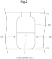
- Fig. 2 is a view showing an example of a positional relation between a container 500 and a marker 230.
- Fig. 3 is a view for describing an example of movement of the container 500.
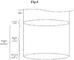
- Fig. 4 is a view for describing a region of interest.
- Fig. 5 is a view for describing a swing center axis.
- Fig. 6 is a view for describing a position of a camera 300.
- Fig. 7 is a block diagram showing an example of a configuration of a determination apparatus 400.
- Fig. 1 is a view showing an example of a configuration of a determination system 100.
- Fig. 2 is a view showing an example of a positional relation between a container 500 and a marker 230.
- Fig. 3 is a view for describing an example of movement of the container 500.
- Fig. 4 is a view for describing a
- Fig. 8 is a flowchart showing an example of operations of a grasping device 200 and the camera 300.
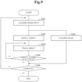
- Fig. 9 is a flowchart showing an example of an operation of the determination apparatus 400.
- Fig. 10 is a flowchart showing an example of processing by a determination unit 445.
- Fig. 11 is a view showing an example of a configuration of a grasping device 600, which is another grasping device included by the determination system 100.
- Fig. 12 is a view for describing the example of the configuration of the grasping device 600 that is the other grasping device.
- a determination system 100 that detects objects mixed in the container 500 filled with liquid such as water or medicine and determines foreign matter such as hair or glass chip among the detected objects.
- the determination system 100 tilts/swings the container 500 while sandwiching and grasping the container 500.
- a marker 230 is provided at a part that tilts in synchronism with the container 500 when the container 500 is tilted. According to such a configuration, a scratch and a stain on the container 500, adhering matter located outside the filled liquid and the like move in conjunction with the movement of the marker 230. As a result, it becomes possible to easily determine a scratch and a stain on the container 500, adhering matter located outside the filled liquid and the like based on image data showing the container 500 and the marker 230 captured and acquired by the fixed camera 300.
- a side of the container 500 on which liquid is filled is defined as the upper side, and the opposite side is defined as the lower side.
- the liquid filled inside the container 500 gathers on the lower side of the container 500.
- Fig. 1 is a side view showing an example of a configuration of the overall determination system 100.
- the determination system 100 includes, for example, a grasping device 200 having a motor 240 serving as a rotating means, a camera 300, and a determination apparatus 400.
- the camera 300 and the determination apparatus 400 are connected so as to be able to communicate with each other by wire or wirelessly.
- the determination apparatus 400 and the grasping device 200 can be connected so as to be able to communicate with each other by wire or wirelessly.
- the grasping device 200 is a device which tilts/swings and rotates the container 500 while sandwiching and grasping the container 500 filled with liquid from above and below.
- the grasping device 200 has, for example, a body unit 210 including a grasping part including an upper grasping part 213 and a lower grasping part 214, an area light source 220, a marker 230, and a motor 240.
- the body unit 210 tilts/swings and rotates in accordance with rotation of the motor 240 functioning as a rotating means.
- the body unit 210 has a rectangular shape when viewed from the front.
- a material that forms the body unit 210 is not particularly limited.
- the body unit 210 may be formed by any material such as resin or metal.
- the shape of the body unit 210 may be other than the shape illustrated above.
- Fig. 1 shows an example when the body unit 210 is viewed from the side.
- the body unit 210 includes, for example, a flat portion 211 connected to the motor 240, an arm part 212 extending from an upper end and a lower end of the flat portion 211 toward the opposite side to a side on which the motor 240 is located, and the grasping part that is formed at an end of the arm part 212 on the opposite side to the side where the motor 240 is located and that sandwiches and grasps the container 500.
- the grasping part includes the upper grasping part 213 that protrudes downward from the arm part 212 formed on the upper side and contacts the top of the container 500 (the side where liquid is filled in), and the lower grasping part 214 that protrudes upward from the arm part 212 formed on the lower side and contacts the bottom of container 500. As shown in Fig. 1 , since the upper grasping part 213 contacts the container 500 from the top of the container 500 and the lower grasping part 214 contacts the container 500 from the bottom of the container 500, the grasping part thereby sandwiches and grasps the container 500 from above and below.
- the upper grasping part 213 and the lower grasping part 214 can be configured to be adjustable in length.
- the length adjustment function may be implemented by using a known means, for example, by configuring the upper grasping part 213 and the lower grasping part 214 so as to have a first portion and a second portion, respectively, to make the first portion and the second portion slidable and fixable at any position.
- the area light source 220 (light source) emits light to the liquid filled in the container 500.
- the area light source 220 has a shape corresponding to the shape of the body unit 210, such as a rectangular shape when viewed from front.
- the area light source 220 may have a shape other than the illustrated shape.
- the area light source 220 is installed on the opposite side to a side where the camera 300 is installed when viewed from the container 500 and the grasping part.
- the area light source 220 is installed on a surface of the flat portion 211 configuring the body unit 210 on the opposite side to the side where the motor 240 is located.
- the area light source 220 emits light to the camera 300 through the container 500. That is to say, it can be said that the area light source 220 is installed in the body unit 210 so as to emit light to the camera 300 through the container 500.
- the area light source 220 is installed on the flat portion 211 of the body unit 210, it can be said that the area light source 220 is configured integrally with the body unit 210 including the upper grasping part 213 and the lower grasping part 214. Therefore, for example, when the container 500 grasped by the upper grasping part 213 and the lower grasping part 214 is tilted, the area light source 220 is also tilted in synchronism with the tilt of the container 500.
- the marker 230 is a structure for enabling acquisition of a rotation angle based on image data captured by the camera 300.
- the marker 230 is, for example, a film that has a rectangular shape having a size of about 0.5 mm square or a circular shape and does not transmit light, and is installed in a predetermined position on the area light source 220.
- the marker 230 may be a two-dimensional code or the like containing any information.
- the marker 230 is installed at a predetermined position on the area light source 220 so that at least one marker 230 is shown in image data acquired by the fixedly installed camera 300 even when the container 500 is tilted.
- Fig. 2 shows an example of an installation position of the marker 230.
- the markers 230 are set at two positions; a position outside the container 500 near the left side surface of the container 500 and a position outside the container 500 near the right side surface of the container 500 in a state where the container 500 is not tilted.
- the markers 230 are provided at a height approximately equal to the height of a swing center axis A, which is an axis when the container 500 is tilted.
- the marker 230 may be installed at a position other than the position illustrated above. Moreover, the number of the markers 230 to be installed may be determined freely, such as one or three or more.
- the marker 230 may be installed on any part other than the area light source as long as it is a part that moves in synchronism with the body unit 210 including the upper grasping part 213 and the lower grasping part 214.
- the marker 230 may be implemented by a protruding part or the like that protrudes toward the container 500 from a part of the body unit 210 located on the side surface of the container 500 when the container 500 is grasped.
- the marker 230 may be implemented by a method other than the method illustrated above.
- the motor 240 By rotating in accordance with electric power supplied from outside, the motor 240 functions as a rotating means (tilting unit) that tilts the body unit 210 to tilt/swing and rotate the container 500 grasped by the upper grasping part 213 and the lower grasping part 214.
- the motor 240 is connected to the flat portion 211 of the body unit 210, and the motor 240 can tilt/swing and rotate the body unit 210 by rotating.
- Fig. 3 shows an example of how the container 500 grasped by the upper grasping part 213 and the lower grasping part 214 is tilted.
- the motor 240 can tilt the container 500 in a forward direction (for example, counterclockwise direction) and tilt the container 500 in a reverse direction (for example, clockwise direction).
- the motor 240 can tilt/swing the container 500 so that the state of the container 500 transits in an order of a state in which the container 500 is not tilted (0 degrees), a state in which the container 500 is tilted 90 degrees in the forward direction, a state in which the container 500 is not tilted, a state in which the container 500 is tilted 90 degrees in the reverse direction, and a state in which the container 500 is not tilted That is to say, the motor 240 can swing the container 500 around the swing center axis A while switching between the normal and reverse directions.
- the swing rotation axis A is not adjusted to be a center height A of the container 500 when the container 500 is not tilted, but adjusted to be a liquid level height B or a liquid center height C (or between the liquid level height B and the liquid center height C, or the like) when the container 500 is not tilted.
- the swing center axis Ato be the center when the body unit 210, the grasped container 500 and the like tilt is determined in accordance with a position where the motor 240 and the flat portion 211 are connected. Moreover, by adjusting the lengths of the upper grasping part 213 and the lower grasping part 214, it is possible to adjust the positional relation between the swing center axis A and the container 500 and between the swing center p A and the liquid filled inside the container 500.
- An angle at which the motor 240 tilts the container 500 is not limited to being up to 90 degrees.
- the angle at which the motor 240 tilts the container 500 may be determined as necessary in accordance with the property of the liquid filled in the container 500 and the property of foreign matter to be detected.
- the motor 240 can start and stop swing in accordance with an instruction received from the determination apparatus 400 to be described later.
- the motor 240 may start and stop swing manually, for example.
- the camera 300 is an imaging device that images the container 500 to acquire image data.
- the camera 300 is previously installed at a predetermined position on the opposite side to a side where the area light source 220 is located when viewed from the upper grasping part 213 and the lower grasping part 214.
- the grasping device 200 and the camera 300 are not configured integrally. Therefore, the camera 300 does not tilt even when the body unit 210 and others are tilted. That is to say, in this example embodiment, the camera 300 acquires image data in a state fixed at the previously installed position.
- the camera 300 acquires image data at a high frame rate of approximately 150 to 200 fps. Then, the camera 300 transmits the acquired image data to the determination apparatus 400 together with information indicating the imaging time, and the like.
- the camera 300 may acquire image data at a frame rate other than that illustrated above.
- the camera 300 it is desirable to install the camera 300 so that a region where the inside of the liquid and the liquid level overlap within a range where the entire liquid filled in the container 500 is shown is as small as possible. For example, it is desirable to install the camera 300 so as to capture an image from a direction as horizontal as possible to the liquid level.
- the installation position of the camera 300 is desirably in a state as shown in Fig. 6 , for example.
- the center height of the camera 300 is set to be at a position equal to or lower than the liquid level and higher than the bottom of the bottle and the entire bottom of the bottle is shown. It can also be seen that the center height of the camera 300 is set to be lower than the height of the liquid level and is as close to the height of the liquid level as possible.
- the determination apparatus 400 is an information processing apparatus that detects an object mixed inside the container 500 filled with a liquid and determines foreign matter based on image data captured/acquired by the camera 300.
- Fig. 7 shows an example of a configuration of the determination apparatus 400. Referring to Fig. 7 , the determination apparatus 400 has, as major components, a screen display unit 410, a communication I/F unit 420, a storage unit 430, and an operation processing unit 440, for example.
- the screen display unit 410 includes a screen display device such as a LCD (Liquid Crystal Display).
- the screen display unit 410 can display on a screen various kinds of information stored in the storage unit 43 such as image information 431, tracking information 432 and determination result information 433 in accordance with an instruction from the operation processing unit 440.
- the communication I/F unit 420 includes a data communication circuit.
- the communication I/F unit 420 performs data communication with the camera 300, an external device and the like connected via a communication line.
- the storage unit 430 is a storage device such as a hard disk and a memory.
- the storage unit 430 stores therein processing information necessary for various kinds of processing by the operation processing unit 440 and a program 434.
- the program 434 is loaded to and executed by the operation processing unit 440 to implement various kinds of processing units.
- the program 434 is previously loaded from an external device or a recording medium via a data input/output function such as the communication I/F unit 420, and is stored in the storage unit 430.
- Major information stored in the storage unit 430 are, for example, the image information 431, the tracking information 432, and the determination result information 433.
- the image information 431 includes image data acquired by the camera 300.
- the image data is associated with information indicating time and date of acquisition of the image data by the camera 300 (information indicating the imaging time).
- the tracking information 432 includes information corresponding to the result of tracking by a tracking unit 343.
- identification information assigned to each object is associated with time-series information indicating the position of the object.
- the time-series information indicating the position of the object includes, for example, time information and position information such as coordinates indicating the position of the object at each time.
- the tracking information 432 may include, other than the time-series information of the position of the object, for example, time-series information of angle information indicating the angle of the container 500, information indicating the area of a detection region, and the like.
- the position information such as the coordinates indicating the position of the object may indicate XY coordinates in each image data, or may indicate coordinates obtained by correcting the XY coordinates in each image data based on the information indicating the angle of the container 500 (for example, coordinates obtained by correcting to a position when the container 500 is not tilted).
- the determination result information 433 includes information indicating the result of determination by the determination unit 445.
- identification information assigned to each object is associated with information indicating the result of determination based on the tracking information 432 by the determination unit 445. That is to say, the determination result information 433 includes information indicating whether the detected object is foreign matter, an air bubble, or a scratch, a stain or the like on the container.
- the operation processing unit 440 has a microprocessor such as a MPU and a peripheral circuit thereof.
- the operation processing unit 440 loads the program 434 from the storage unit 434 and executes the program 434 to make the abovementioned hardware cooperate with the program 434 and implement various kinds of processing units.
- Major processing units implemented by the operation processing unit 440 are, for example, an image acquisition unit 441, a detection unit 442, a tracking unit 443, an angle information acquisition unit 444, a determination unit 445, and an output unit 446.
- the image acquisition unit 441 acquires image data acquired by the camera 300 from the camera 300 via the communication I/F unit 420. Then, the image acquisition unit 441 associates the acquired data with, for example, time and date of acquisition of the image data (information indicating the imaging time), and stores as the image information 431 into the storage unit 430.
- the detection unit 442 detects an object existing within a region corresponding to the container 500 and liquid filled in the container 500. For example, the detection unit 442 performs a binarization process on the image data and detects an object based on the result of the binarization process. Meanwhile, the detection unit 442 may detect an object by using other known techniques.
- the tracking unit 443 tracks an object detected by the detection unit 442. As described above, the camera 300 acquires image data at a high frame rate such as 200 fps. Therefore, it is assumed that the positions of the same object are extremely close between two pieces of image data with consecutive imaging times (the imaging times are closer than a predetermined value). Then, the tracking unit 443 compares the position of an object detected by the detection unit 442 with the position of an object detected by the detection unit 442 in image data with the previous imaging time (or within a predetermined value).
- the tracking unit 443 determines that the object detected by the detection unit 442 and the object detected by the detection unit 442 in the image data with the previous imaging time that are separated by a distance equal to or less than the threshold value are the same objects. In this case, the tracking unit 443 provides the object detected by the detection unit 442 with identification information such as ID provided to the object determined to be the same object. On the other hand, in a case where the image data with the previous imaging time (or within the predetermined value) does not show an object with a distance equal to or less than the predetermined threshold value from the object detected by the detection unit 442, the tracking unit 443 determines that a new object is detected. In this case, the tracking unit 443 provides the detected object with identification information such as new ID.
- the tracking unit 443 provides an object detected by the detection unit 442 with identification information by performing tracking based on a distance between objects in different image data. Moreover, the tracking unit 443 acquires coordinates indicating the position of the object detected by the detection unit 442. Then, the tracking unit 443 associates the identification information, time information indicating the imaging time of the image data, and the coordinates, and stores as the tracking information 432 into the storage unit 430.
- the tracking unit 443 may store XY coordinates in the image data into the storage unit 430 as the tracking information 432, or may store coordinates obtained by correcting XY coordinates in each image data based on information indicating the angle of the container 500 acquired by the angle information acquisition unit 444 (for example, coordinates corrected to a position in a case where the container 500 is not tilted) into the storage unit 430 as the tracking information 432.
- the angle information acquisition unit 444 acquires angle information indicating an angle at which the container 500 is tilted based on the position of the marker 230 in image data. For example, calibration of the tilt angle of the container 500 and the position of the marker 230 in the image data is performed in advance. Therefore, the angle information acquisition unit 444 can acquire angle information indicating an angle at which the container 500 is tilted based on the position of the marker 230 in the image data.
- the angle information acquisition unit 444 can store the acquired angle information into the storage unit 430 together with time information indicating the imaging time of the image data. As described above, the angle information acquisition unit 444 may store the angle information into the storage section 430 as one of the information included by the tracking information 432.
- the determination unit 445 determines whether an object detected by the detection unit 442 is an air bubble, foreign matter, or a scratch, stain or adhering matter on the container 500.
- the determination unit 445 can perform a determination based on time-series information while the container 500 is swinging and a determination based on time-series information after the swing is finished (that is, after the container 500 stops in the state shown in Fig. 1 ).
- the determination unit 445 can determine whether or not the container 500 is swinging based on the angle information included by the tracking information 432.
- the determination unit 445 determines whether or not an object detected by the detection unit 442 is a scratch or stain on the container 500 or adhering matter adhering to the container 500 based on the time-series information while the container 500 is swinging included by the tracking information 432.
- the marker 230 is installed on the area light source 220 installed on the body unit 210 that tilts in synchronism with the container 500. Therefore, a scratch and a stain on the container 500, an adhering matter located outside the filled liquid and the like move in conjunction with the movement of the marker 230.
- the movement in conjunction described above refers to movement in full conjunction such that, when the marker 230 starts movement, a scratch and a stain on the container 500, adhering matter located outside the filled liquid and the like immediately start movement and, when the marker 230 stops movement, the scratch and stain on the container 500, the adhering matter located outside the filled liquid and the like immediately stop movement.
- the determination unit 445 determines that an object moving in conjunction with the movement of the marker 230 among the objects detected by the detection unit 442 is a scratch or stain on the container 500, adhering matter, or the like based on the time-series information while the container 500 is swinging.
- the determination unit 445 determines that an object which is not moving in conjunction with the movement of the marker 230 among the objects detected by the detection unit 442 is not a scratch or stain on the container 500, adhering matter, or the like. That is to say, the determination unit 445 determines that the object that is not moving in conjunction with the movement of the marker 230 is possibly an air bubble or foreign matter.
- the determination unit 445 determines whether the object detected by the detection unit 442 is an air bubble or foreign matter based on the time-series information after the swing is finished included by the tracking information 432.
- the determination unit 445 can perform the above determination on all the objects detected by the detection unit 442, excluding an object determined by the determination unit 445 as a scratch, a stain or adhering matter on the container. For example, in a case where it is determined that the object is moving upward based on the time-series information after the swing stops, the determination unit 445 determines that the object is an air bubble. On the other hand, in a case where it is determined that the object is moving downward based on the time-series information after the swing stops, the determination unit 445 determines that the object is foreign matter.
- the determination unit 445 can determine whether the object is an air bubble or foreign matter based on the movement direction of the object indicated by the time-series information after the swing stops. Meanwhile, the determination unit 445 may determine whether the object is an air bubble or foreign matter by a method other than the method illustrated above, such as performing the determination by using a model that has been learned in advance.
- the determination unit 445 determines whether the remaining object is an air bubble or foreign matter. Then, the determination unit 445 stores the result of determination of the respective objects detected by the detection unit 442 as the determination result information 433 into the storage unit 430.
- a timing at which the determination unit 445 performs the determination is not particularly limited.
- the determination unit 445 may be configured to determine in real time while the container 500 is swinging whether or not the object is a scratch or the like, or may be configured to perform the series of processing described above after the time-series data during and after the swing are completed.
- the determination unit 445 may be configured to perform the determination of movement in conjunction with the marker 230 and the determination whether the object is an air bubble or foreign matter in parallel. That is to say, the determination unit 445 may start the determination whether the object is an air bubble or foreign matter before the swing finishes. Moreover, the determination unit 445 may use information other than the tracking information 432 when determining the object. For example, the determination unit 445 can determine the object by using information indicating the image characteristics of the object, the size, the average luminance value, and the like. By performing the determination also using information other than movement, such as the size of the object and average luminance value, it is possible to comprehensively judge the characteristics of an air bubble and foreign matter, and consequently, higher determination accuracy can be obtained.
- the output unit 446 outputs the image information 431, the tracking information 432, the determination result information 433 and the like.
- the output unit 446 can display the image information 431, the tracking information 432, the determination result information 433 and the like on the screen display unit 410, and transmit them to an external device via the communication I/F unit 420.
- the above is an example of the configuration of the determination apparatus 400.
- the determination apparatus 400 may have a configuration other than that described above.
- the determination apparatus 400 can be configured to instruct the grasping device 200 to start swing or to stop swing.
- the determination apparatus 400 can instruct the grasping device 200 to stop swing.
- the determination apparatus 400 can instruct the grasping device 200 to perform a rotation operation for peeling off foreign matter and the like fixedly adhering to the wall surface of the container 500 before instructing the start of swing. That is to say, the determination apparatus 400 may be configured to instruct the start of swing after instructing the rotation operation.
- the container 500 is a translucent container such as a glass bottle or a plastic bottle.
- the inside of the container 500 is filled with liquid such as water or medicine.
- the container 500 may have a scratch, a stain and the like.
- foreign matter may be mixed inside the container 500. Examples of foreign matter include a rubber piece, hair, a fiber piece, soot, and a glass or plastic chip.
- the above is an example of the configurations of the grasping device 200, the camera 300, the determination apparatus 400, and the container 500 included by the determination system 100.
- an example of an operation of the determination system 100 will be described with reference to Figs. 8 to 10 .
- Fig. 8 the relation between a timing at which the grasping device 200 swings the container 500 and a timing at which the camera 300 captures an image will be described.
- the grasping device 200 tilts the container 500, for example, in accordance with an instruction by the determination apparatus 400 (step S101). That is to say, the grasping device 200 starts swing. Moreover, for example, at a timing at which the grasping device 200 starts swing, the camera 300 starts capturing an image (step S201). The camera 300 may start capturing an image before the grasping device 200 starts swing, or may start capturing an image after the grasping device 200 starts swing.
- the grasping device 200 stops swing, for example, in accordance with an instruction by the determination apparatus 400 (step S102). As shown in Fig. 8 , at a timing that the grasping device 200 stops swing, the camera 300 does not finish capturing an image. Therefore, the camera 300 captures an image while the grasping device 200 swinging the container 500, and also continues capturing an image after the grasping device 200 stops swing.
- the camera 300 finishes capturing an image (step S202).
- a condition that the camera 300 finishes capturing an image is not specifically limited.
- the camera 300 can finish capturing an image in a case where a predetermined condition is satisfied, for example, a predetermined time has passed since the start of swing, a predetermined time has passed after the stop of swing, or the determination by the determination unit 445 has been completed for all objects detected by the detection unit 442.
- the above is an example of the relation between the timing at which the grasping device 200 swings the container 500 and the timing at which the camera 300 captures an image.
- the camera 300 captures an image of the grasping device 200 swinging the container 500, and also continues capturing an image after the swing stops.
- an example of an operation of the overall determination apparatus 400 will be described with reference to Fig. 9 .
- the image acquisition unit 441 acquires image data acquired by the camera 300 from the camera 300 via the communication I/F unit 420 (step S301).
- the detection unit 442 detects an object existing within a region corresponding to the container 500 and liquid filled in the container 500 based on the image data (step S302).
- the detection unit 442 may detect the object by using a known technique.
- the tracking unit 443 tracks the object detected by the detection unit 442 (step S303). For example, the tracking unit 443 tracks the object based on a distance between objects in image data with close (or consecutive) imaging times.
- the tracking unit 443 In a case where the tracking unit 443 has not tracked all the objects detected by the detection unit 422 in the image data (step S304, No), the tracking unit 443 tracks an object having not been tracked. On the other hand, in a case where the tracking unit 443 has tracked all the objects detected by the detection unit 422 in the image data (step S304, Yes), the tracking unit 443 completes the tracking.
- the angle information acquisition unit 444 acquires angle information indicating an angle at which the container 500 tilts based on the location of the marker 230 in the image data (step S305).
- step S306, Yes the determination apparatus 400 finishes the processing.
- step S306, No the image acquisition unit 441 acquires the image data from the camera 300 (step S301).
- the determination apparatus 400 may perform the processing in an order other than that illustrated above, such as performing the processing at step S302 and later after acquiring all of the series of image data captured by the camera 300.
- the determination unit 445 will be described with reference to Fig. 10 .
- the determination unit 445 acquires time-series information while the container 500 is swinging included by the tracking information 432 (step S401).
- the determination unit 445 determines that the object moving in conjunction with the movement of the marker 230 is a scratch, stain, adhering matter or the like on the container 500 (step S403). Then, the determination unit 445 excludes the object determined to be a scratch, stain, adhering matter or the like on the container 500 from objects to be determined in a process at step S407 (step S404).
- the determination unit 445 determines that the object not moving in conjunction with the movement of the marker 230 is not a scratch, stain, adhering matter or the like on the container 500 (step S405).
- the determination unit 445 acquires time-series information after the container 500 stops swinging included by the tracking information 432 (step S406). Then, the determination unit 445 determines whether the object detected by the detection unit 442 is an air bubble or foreign matter based on the time-series information after the swing finishes included by the tracking information 432 (step S407). For example, the determination unit 445 can determine whether the object is an air bubble or foreign matter based on the moving direction of the object indicated by the time-series information after the swing stops. The determination unit 445 may perform the determination by a method other than that illustrated above.
- a timing at which the determination unit 445 performs the determination is not specifically limited.
- the determination unit 445 may be configured to determine whether or not the object is a scratch or the like in real time while the container 500 is swinging, or may perform the series of processing described above after the time-series data during and after the swing are obtained.
- the grasping device 200 has the marker 230 installed on the area light source 220 that tilts in synchronism with the container 500 when tilting the grasped container 500.
- the marker 230 installed on the area light source 220 that tilts in synchronism with the container 500 when tilting the grasped container 500.
- angle information indicating an angle at which the container 500 tilts can be easily acquired.
- the angle information can be acquired, for example, from an encoder of the motor 240 serving as a rotating means, acquisition of the angle information from the encoder makes the configuration of the determination system 100 complicated. By installing the marker 230 as described above, it becomes possible to easily acquire the angle information without making the configuration complicated.
- the determination unit 445 can determine whether an object excluding the scratch and the like on the container 500 beforehand is an air bubble or foreign matter. As a result, it is possible to suppress erroneous determination of a scratch and the like on the container 500 as an air bubble or foreign matter, and it is possible to increase the accuracy of the determination.
- the configuration of the determination system 100 is not limited to that illustrated in this example embodiment.
- the determination system 100 may have a grasping device 600 as shown in Figs. 11 and 12 instead of the grasping device 200 illustrated in Fig. 1 and others.
- the grasping device 600 is a device that sandwiches and grasps the container 500 filled with liquid from above and below and tilts the container 500 in this state.
- the grasping device 600 includes, for example, a body unit 610 including a grasping part including an upper grasping part 611 and a lower grasping part 612, an area light source 620, a gear 630, and a motor 640.
- the body unit 610 tilts/swings and rotates in accordance with the rotation of the gear 630 and the motor 640 that function as a rotating means.
- the body unit 610 has a cylindrical shape and is configured to be able to grasp the container 500 inside.
- the body unit 610 may be formed by any material.
- the shape of the body unit 610 may be other than that illustrated above.
- Fig. 11 shows an example of the body unit 610 viewed from the side
- Fig. 12 shows an example of the main body 610 viewed from the front.
- the body unit 610 includes the grasping part for grasping the container 500 and a pair of marker parts 613 protruding toward the container 500 from parts of the body unit 610 located on the side surface of the container 500 when the container 500 is grasped.
- the body unit 610 meshes with the gear 630 and is configured to tilt/swing in accordance with the rotation of the gear 630.
- the grasping part includes the upper grasping part 611 formed on the upper inner peripheral surface of the body unit 610 and protruding downward, and the lower grasping part 612 formed on the lower inner peripheral surface of the body unit 610 and protruding upward. As shown in Fig. 12 , the upper grasping part 611 contacts the container 500 from above the container 500, the lower grasping part 612 contacts the container 500 from below the container 500, and the grasping part thereby sandwiches the container 500 from above and below and grasps the container 500.
- the upper grasping part 611 and the lower grasping part 612 may be configured to be adjustable in length.
- the marker part 613 is a structure for enabling acquisition of a rotation angle based on image data captured by the camera 300. In the vicinity of the inner tip of the marker part 613, a two-dimensional code or the like may be installed.
- the marker part 613 can employ various modification examples as well as the marker 230.
- the area light source 620 emits light to liquid filled inside the container 500.
- the area light source 620 may have a shape corresponding to the shape of the body unit 610, such as a circular shape when viewed from the front, or may be a rectangular shape or the like.
- the area light source 620 is installed on the opposite side to a side where the camera 300 is installed when viewed from the container 500 and the grasping part.
- the area light source 620 may be configured not to be integral with the body unit 610.
- the area light source 620 may be configured to be integral with the body unit 610.
- the gear 630 and the motor 640 function as a rotating means for rotating the body unit 610.
- the motor 640 rotates in accordance with electric power supplied from outside, and thereby rotates the gear 630.
- the gear 630 transmits the rotation of the motor 640 to the body unit 610. Consequently, the body unit 610 tilts/swings in accordance with the rotation of the motor 640.
- the determination system 100 may have the grasping device 600 instead of the grasping device 200.
- the determination system 100 having the grasping device 600 can also have the same action and effect as in the case of having the determination device 200.
- the grasping device included by the determination system 100 may have a characteristic that combines the characteristic of the grasping device 200 and the characteristic of the grasping device 600.
- the function of the determination apparatus 400 may be implemented by a plurality of information processing apparatuses connected via a network.
- the determination apparatus 400 can be configured to instruct the grasping device 200 to start swing and stop swing.
- the determination system 100 may have an instruction apparatus that performs the above instruction as an apparatus different from the determination apparatus 400.
- a second example embodiment of the present invention will be described with reference to Figs. 13 to 15 .
- the outline of configurations of a grasping device 700 and a determination apparatus 800 will be described.
- Fig. 13 shows an example of the configuration of the grasping device 700.
- the grasping device 700 includes a grasping unit 710, a tilting unit 720, and a marker 730.
- the gasping unit 710 grasps a container filled with liquid.
- the tilting unit 720 at least tilts the container in a state where the grasping unit 710 grasps the container.
- the tilting unit 720 is a motor or the like, and tilts the container by tilting the grasping unit 710.
- the marker 730 is installed at a part tilting in synchronism with the container when the container tilts, and moves in conjunction with the movement of the container.
- the marker 730 is installed on the grasping unit 710.
- the grasping device 700 includes the grasping unit 710, the tilting unit 720, and the marker 730.
- the grasping unit 710 when the grasped container is tilted, a scratch and stain on the container, and adhering matter and the like located outside the filled liquid move in conjunction with the movement of the marker 730.
- a scratch and stain on the container, and adhering matter and the like located outside the filled liquid can be easily determined.
- Fig. 14 shows an example of a hardware configuration of the determination apparatus 800.
- the determination apparatus 800 has, as an example, a hardware configuration as shown below including;
- the determination apparatus 800 can implement the functions of a detection unit 821, a tracking unit 822, and a determination unit 823 shown in Fig. 15 .
- the programs 804 are, for example, stored in the storage device or the ROM 805 in advance, and are loaded to the RAM 803 or the like and executed by the CPU 801 as necessary.
- the programs 804 may be supplied to the CPU 801 via the communication network 811, or may be stored in the recording medium 810 in advance and retrieved and supplied to the CPU 801 by the drive device 806.
- Fig. 14 shows an example of the hardware configuration of the determination apparatus 800.
- the hardware configuration of the determination apparatus 800 is not limited to that described above.
- the determination apparatus 800 may be configured by part of the above configuration, for example, excluding the drive device 806.
- the detection unit 821 detects an object based on image data showing liquid filled in a container and a marker moving in conjunction with movement of the container.
- the tracking unit 822 tracks the object detected by the detection unit 821.
- the determination unit 823 determines the object detected by the detection unit 821 based on the result of the tracking by the tracking unit 822 and the movement of the marker. For example, the determination unit 823 determines whether the object is foreign matter, an air bubble, or a scratch or the like on the container.
- the determination apparatus 800 includes the detection unit 821, the tracking unit 822, and the determination unit 823.
- the determination unit 823 can perform determination of an object detected by the detection unit 821 based on the result of tracking by the tracking unit 822 and the movement of the marker.
- the determination unit 823 can perform determination of an object detected by the detection unit 821 based on the result of tracking by the tracking unit 822 and the movement of the marker.
- the determination apparatus 800 described above can be implemented by installation of a predetermined program in the determination apparatus 800.
- a program as another aspect of the present invention is a program for causing the determination apparatus 800 to implement: the detection unit 821 that detects an object based on image data showing liquid filled in a container and a marker moving in conjunction with movement of the container; the tracking unit 822 that tracks the object detected by the detection unit 821; and the determination unit 823 that performs determination of the object based on the result of the tracking by the tracking unit 822 and the movement of the marker.
- a determination method executed by the determination apparatus 800 described above is a method including, by the determination apparatus 800: detecting an object based on image data showing liquid filled in a container and a marker moving in conjunction with movement of the container; tracking the detected object; and performing determination of the detected object based on the result of the tracking and the movement of the marker.
- a grasping device comprising:
- the grasping device according to any one of Supplementary Notes 1 to 4, wherein the tilting unit is configured to tilt the container in a clockwise direction and also tilt the container in a counterclockwise direction.
- a determination system comprising:
- a determination apparatus comprising:
- the determination apparatus configured to perform determination of the object based on movement of the object identified as the result of tracking by the tracking unit and the movement of the marker.
- the determination apparatus according to Supplementary Note 8, wherein the determination unit is configured to determine whether the object is an air bubble or foreign matter.
- the determination apparatus configured to, when the movement of the object and the movement of the marker are in conjunction, determine that the object is a scratch or a strain on the container or adhering matter adhering to the container.
- the determination apparatus according to any one of Supplementary Notes 8 to 10, wherein the determination unit is configured to determine whether or not the movement of the object and the movement of the marker are in conjunction, and also determine whether the object is an air bubble or foreign matter based on the result of tracking by the tracking unit.
- the determination apparatus according to any one of Supplementary Notes 8 to 11, wherein the determination unit is configured to, in accordance with determination based on whether or not the movement of the object and the movement of the marker are in conjunction, identify the object that is a scratch or a stain on the container or adhering matter adhering to the container, and determine whether the object excluding the identified object among the objects detected by the detection unit is an air bubble or foreign matter.
- a determination method comprising, by a determination apparatus:
- the program described in the example embodiments and supplementary notes is stored in a storage device, or recorded on a computer-readable recording medium.
- the recording medium is a portable medium such as a flexible disk, an optical disk, a magnetooptical disk, and a semiconductor memory.
Landscapes
- Engineering & Computer Science (AREA)
- Physics & Mathematics (AREA)
- General Physics & Mathematics (AREA)
- Theoretical Computer Science (AREA)
- Computer Vision & Pattern Recognition (AREA)
- Life Sciences & Earth Sciences (AREA)
- Health & Medical Sciences (AREA)
- Chemical & Material Sciences (AREA)
- Analytical Chemistry (AREA)
- Biochemistry (AREA)
- General Health & Medical Sciences (AREA)
- Immunology (AREA)
- Pathology (AREA)
- Quality & Reliability (AREA)
- Multimedia (AREA)
- Investigating Materials By The Use Of Optical Means Adapted For Particular Applications (AREA)
Abstract
Description
- The present invention relates to a grasping device, a determination system, a determination apparatus, a determination method, and a recording medium.
- A technique for detecting foreign matter in liquid in a container is known.
- One of the techniques used in detecting foreign matter is described in Patent Document 1, for example. Patent Document 1 describes a system which includes a reversing device, an imaging device, and an image processing device. According to Patent Document 1, the reversing device tilts or inverts a held object to be inspected and returns the object to its original posture. The imaging device captures an image of the object to be inspected immediately after being tilted or inverted and returned to its original posture by the reversing device. The image processing device processes the image captured by the imaging device and determines whether the object to be inspected is good or bad. Patent Document 1 discloses tilting or inverting an object to be inspected around a rotation center axis located above the object to be inspected.
- Further, a related technique is described in Patent Document 2, for example. Patent Document 2 describes a method to detect foreign matter by selecting an air bubble and a stain and the like on a container based on a difference image and removing the selected air bubble and stain and the like.
- Patent Document 1: International Publication No.
WO 2005-031328 - Patent Document 2: Japanese Unexamined Patent Application Publication No.
JP-A 2004-354100 - In detecting foreign matter with accuracy, it is required to distinguish foreign matter from an air bubble and a scratch, a stain and the like attaching to a container. However, unlike foreign matter, an air bubble and the like, a scratch, a stain and the like attaching to a container do not move in a state where the container is stationary. Therefore, with the techniques described in Patent Document 1 and Patent Document 2, which are performing detection based on the result of imaging a container in a stationary state, it may be difficult to distinguish a scratch, a stain and the like attaching to the container.
- Accordingly, an object of the present invention is to provide a grasping device, a determination system, a determination apparatus, a determination method, and a recording medium that make it possible to easily determine a scratch, a stain and the like attaching to a container in detecting foreign matter.
- In order to achieve the object, a grasping device as an aspect of the present disclosure includes: a grasping unit configured to grasp a container filled with liquid; a tilting unit configured to at least tilt the container in a state where the grasping unit grasps the container; and a maker installed at a part tilting in synchronism with the container when the container tilts and configured to move in conjunction with movement of the container.
- Further, a determination system as another aspect of the present disclosure includes: a grasping device including a grasping unit configured to grasp a container filled with liquid, a tilting unit configured to at least tilt the container in a state where the grasping unit grasps the container, and a maker installed at a part tilting in synchronism with the container when the container tilts and configured to move in conjunction with movement of the container; a camera installed outside the grasping device and configured to image the liquid filled in the container; and a determination apparatus configured to detect an object based on image data obtained by the camera and determine whether or not the detected object is foreign matter.
- Further, a determination apparatus as another aspect of the present disclosure includes: a detection unit configured to detect an object based on image data showing liquid filled in a container and a marker moving in conjunction when the container moves; a tracking unit configured to track the object detected by the detection unit; and a determination unit configured to perform determination of the object detected by the detection unit based on a result of tracking by the tracking unit and movement of the marker.
- Further, a determination method as another aspect of the present disclosure includes, by a determination apparatus: detecting an object based on image data showing liquid filled in a container and a marker moving in conjunction when the container moves; tracking the detected object; and performing determination of the detected object based on a result of tracking and movement of the marker.
- Further, a recording medium as another aspect of the present disclosure is a non-transitory computer-readable recording medium having a program recorded thereon. The program includes instructions for causing a determination apparatus to implement: a detection unit configured to detect an object based on image data showing liquid filled in a container and a marker moving in conjunction when the container moves; a tracking unit configured to track the object detected by the detection unit; and a determination unit configured to perform determination of the object based on a result of tracking by the tracking unit and movement of the marker.
- With the respective configurations as described above, it is possible to provide a grasping device, a determination system, a determination apparatus, a determination method, and a recording medium that make it possible to easily determine a scratch, a stain and the like attaching to a container in detecting foreign matter.
-
-
Fig. 1 is a view showing an example of a configuration of a determination system in a first example embodiment of the present disclosure; -
Fig. 2 is a view showing an example of a positional relation between a container and a marker; -
Fig. 3 is a view for describing an example of movement of the container; -
Fig. 4 is a view for describing a region of interest; -
Fig. 5 is a view for describing a position of a swing center axis; -
Fig. 6 is a view for describing a position of a camera; -
Fig. 7 is a block diagram showing an example of a configuration of a determination apparatus shown inFig. 1 ; -
Fig. 8 is a flowchart showing an example of operations of a grasping device and the camera in the first example embodiment of the present disclosure; -
Fig. 9 is a flowchart showing an example of an operation of the overall determination apparatus in the first example embodiment of the present disclosure; -
Fig. 10 is a flowchart showing an example of processing by a determination unit; -
Fig. 11 is a view showing an example of a configuration of another grasping device included by the determination system; -
Fig. 12 is a view for describing the configuration example of the other grasping device; -
Fig. 13 is a view showing an example of a configuration of a grasping device in a second example embodiment of the present disclosure; -
Fig. 14 is a view showing an example of a hardware configuration diagram of a determination apparatus in the second example embodiment of the present disclosure; and -
Fig. 15 is a block diagram showing an example of a configuration of the determination apparatus in the second example embodiment of the present disclosure. - A first example embodiment of the present disclosure will be described with reference to
Figs. 1 to 12 .Fig. 1 is a view showing an example of a configuration of adetermination system 100.Fig. 2 is a view showing an example of a positional relation between acontainer 500 and amarker 230.Fig. 3 is a view for describing an example of movement of thecontainer 500.Fig. 4 is a view for describing a region of interest.Fig. 5 is a view for describing a swing center axis.Fig. 6 is a view for describing a position of acamera 300.Fig. 7 is a block diagram showing an example of a configuration of adetermination apparatus 400.Fig. 8 is a flowchart showing an example of operations of agrasping device 200 and thecamera 300.Fig. 9 is a flowchart showing an example of an operation of thedetermination apparatus 400.Fig. 10 is a flowchart showing an example of processing by adetermination unit 445.Fig. 11 is a view showing an example of a configuration of agrasping device 600, which is another grasping device included by thedetermination system 100.Fig. 12 is a view for describing the example of the configuration of thegrasping device 600 that is the other grasping device. - In the first example embodiment of the present disclosure, a
determination system 100 will be described that detects objects mixed in thecontainer 500 filled with liquid such as water or medicine and determines foreign matter such as hair or glass chip among the detected objects. As will be described later, thedetermination system 100 tilts/swings thecontainer 500 while sandwiching and grasping thecontainer 500. Moreover, in thedetermination system 100, amarker 230 is provided at a part that tilts in synchronism with thecontainer 500 when thecontainer 500 is tilted. According to such a configuration, a scratch and a stain on thecontainer 500, adhering matter located outside the filled liquid and the like move in conjunction with the movement of themarker 230. As a result, it becomes possible to easily determine a scratch and a stain on thecontainer 500, adhering matter located outside the filled liquid and the like based on image data showing thecontainer 500 and themarker 230 captured and acquired by thefixed camera 300. - In the description of this example embodiment, in the state shown in
Fig. 1 , a side of thecontainer 500 on which liquid is filled is defined as the upper side, and the opposite side is defined as the lower side. InFig. 1 , the liquid filled inside thecontainer 500 gathers on the lower side of thecontainer 500. -
Fig. 1 is a side view showing an example of a configuration of theoverall determination system 100. Referring toFig. 1 , thedetermination system 100 includes, for example, a graspingdevice 200 having amotor 240 serving as a rotating means, acamera 300, and adetermination apparatus 400. As shown inFig. 1 , thecamera 300 and thedetermination apparatus 400 are connected so as to be able to communicate with each other by wire or wirelessly. Moreover, thedetermination apparatus 400 and the graspingdevice 200 can be connected so as to be able to communicate with each other by wire or wirelessly. - The grasping
device 200 is a device which tilts/swings and rotates thecontainer 500 while sandwiching and grasping thecontainer 500 filled with liquid from above and below. As shown inFig. 1 , the graspingdevice 200 has, for example, abody unit 210 including a grasping part including an uppergrasping part 213 and a lowergrasping part 214, an arealight source 220, amarker 230, and amotor 240. - The
body unit 210 tilts/swings and rotates in accordance with rotation of themotor 240 functioning as a rotating means. For example, thebody unit 210 has a rectangular shape when viewed from the front. Meanwhile, in this example embodiment, a material that forms thebody unit 210 is not particularly limited. Thebody unit 210 may be formed by any material such as resin or metal. Moreover, the shape of thebody unit 210 may be other than the shape illustrated above. -
Fig. 1 shows an example when thebody unit 210 is viewed from the side. Referring toFig. 1 , thebody unit 210 includes, for example, aflat portion 211 connected to themotor 240, anarm part 212 extending from an upper end and a lower end of theflat portion 211 toward the opposite side to a side on which themotor 240 is located, and the grasping part that is formed at an end of thearm part 212 on the opposite side to the side where themotor 240 is located and that sandwiches and grasps thecontainer 500. - The grasping part includes the upper grasping
part 213 that protrudes downward from thearm part 212 formed on the upper side and contacts the top of the container 500 (the side where liquid is filled in), and the lowergrasping part 214 that protrudes upward from thearm part 212 formed on the lower side and contacts the bottom ofcontainer 500. As shown inFig. 1 , since the upper graspingpart 213 contacts thecontainer 500 from the top of thecontainer 500 and the lowergrasping part 214 contacts thecontainer 500 from the bottom of thecontainer 500, the grasping part thereby sandwiches and grasps thecontainer 500 from above and below. - The upper
grasping part 213 and the lowergrasping part 214 can be configured to be adjustable in length. By configuring the upper graspingpart 213 and the lowergrasping part 214 to be adjustable in length, it is possible to graspcontainers 500 of various sizes, and it is also possible to easily perform position adjustment (height adjustment) when the grasping part grasps thecontainer 500. The length adjustment function may be implemented by using a known means, for example, by configuring the upper graspingpart 213 and the lowergrasping part 214 so as to have a first portion and a second portion, respectively, to make the first portion and the second portion slidable and fixable at any position. - The area light source 220 (light source) emits light to the liquid filled in the
container 500. For example, the arealight source 220 has a shape corresponding to the shape of thebody unit 210, such as a rectangular shape when viewed from front. The arealight source 220 may have a shape other than the illustrated shape. - For example, the area
light source 220 is installed on the opposite side to a side where thecamera 300 is installed when viewed from thecontainer 500 and the grasping part. For example, referring toFig. 1 , the arealight source 220 is installed on a surface of theflat portion 211 configuring thebody unit 210 on the opposite side to the side where themotor 240 is located. With such a configuration, the arealight source 220 emits light to thecamera 300 through thecontainer 500. That is to say, it can be said that the arealight source 220 is installed in thebody unit 210 so as to emit light to thecamera 300 through thecontainer 500. - Since the area
light source 220 is installed on theflat portion 211 of thebody unit 210, it can be said that the arealight source 220 is configured integrally with thebody unit 210 including the upper graspingpart 213 and the lowergrasping part 214. Therefore, for example, when thecontainer 500 grasped by the upper graspingpart 213 and the lowergrasping part 214 is tilted, the arealight source 220 is also tilted in synchronism with the tilt of thecontainer 500. - The
marker 230 is a structure for enabling acquisition of a rotation angle based on image data captured by thecamera 300. Themarker 230 is, for example, a film that has a rectangular shape having a size of about 0.5 mm square or a circular shape and does not transmit light, and is installed in a predetermined position on the arealight source 220. Themarker 230 may be a two-dimensional code or the like containing any information. - The
marker 230 is installed at a predetermined position on the arealight source 220 so that at least onemarker 230 is shown in image data acquired by the fixedly installedcamera 300 even when thecontainer 500 is tilted.Fig. 2 shows an example of an installation position of themarker 230. For example, in the case illustrated inFig. 2 , themarkers 230 are set at two positions; a position outside thecontainer 500 near the left side surface of thecontainer 500 and a position outside thecontainer 500 near the right side surface of thecontainer 500 in a state where thecontainer 500 is not tilted. Moreover, in the case illustrated inFig. 2 , themarkers 230 are provided at a height approximately equal to the height of a swing center axis A, which is an axis when thecontainer 500 is tilted. - If at least one
marker 230 is shown in the image of the liquid even when thecontainer 500 is tilted, themarker 230 may be installed at a position other than the position illustrated above. Moreover, the number of themarkers 230 to be installed may be determined freely, such as one or three or more. - Further, the
marker 230 may be installed on any part other than the area light source as long as it is a part that moves in synchronism with thebody unit 210 including the upper graspingpart 213 and the lowergrasping part 214. For example, themarker 230 may be implemented by a protruding part or the like that protrudes toward thecontainer 500 from a part of thebody unit 210 located on the side surface of thecontainer 500 when thecontainer 500 is grasped. Themarker 230 may be implemented by a method other than the method illustrated above. - By rotating in accordance with electric power supplied from outside, the
motor 240 functions as a rotating means (tilting unit) that tilts thebody unit 210 to tilt/swing and rotate thecontainer 500 grasped by the upper graspingpart 213 and the lowergrasping part 214. For example, themotor 240 is connected to theflat portion 211 of thebody unit 210, and themotor 240 can tilt/swing and rotate thebody unit 210 by rotating. -
Fig. 3 shows an example of how thecontainer 500 grasped by the upper graspingpart 213 and the lowergrasping part 214 is tilted. As shown inFig. 3 , themotor 240 can tilt thecontainer 500 in a forward direction (for example, counterclockwise direction) and tilt thecontainer 500 in a reverse direction (for example, clockwise direction). As an example, themotor 240 can tilt/swing thecontainer 500 so that the state of thecontainer 500 transits in an order of a state in which thecontainer 500 is not tilted (0 degrees), a state in which thecontainer 500 is tilted 90 degrees in the forward direction, a state in which thecontainer 500 is not tilted, a state in which thecontainer 500 is tilted 90 degrees in the reverse direction, and a state in which thecontainer 500 is not tilted That is to say, themotor 240 can swing thecontainer 500 around the swing center axis A while switching between the normal and reverse directions. - In capturing image data with the
camera 300, it is desirable that a region of interest (inside liquid and bottom of bottle) as shown inFig. 4 is efficiently held within the angle of view of thecamera 300 even when thecontainer 300 is tilted. Therefore, it is desirable that, for example, as shown inFig. 5 , the swing rotation axis A is not adjusted to be a center height A of thecontainer 500 when thecontainer 500 is not tilted, but adjusted to be a liquid level height B or a liquid center height C (or between the liquid level height B and the liquid center height C, or the like) when thecontainer 500 is not tilted. For example, in the case of the graspingdevice 200 described in this example embodiment, the swing center axis Ato be the center when thebody unit 210, the graspedcontainer 500 and the like tilt is determined in accordance with a position where themotor 240 and theflat portion 211 are connected. Moreover, by adjusting the lengths of the upper graspingpart 213 and the lowergrasping part 214, it is possible to adjust the positional relation between the swing center axis A and thecontainer 500 and between the swing center p A and the liquid filled inside thecontainer 500. Therefore, it can be said to be desirable that a position where themotor 240 and theflat portion 211 are connected and the lengths of the upper graspingpart 213 and the lowergrasping part 214 are determined in advance and corrected as necessary so that the swing center axis A is located at a desirable position in accordance with the size of thecontainer 500, the amount of liquid at the liquid level height B, the liquid center height C or the like, and others. - An angle at which the
motor 240 tilts thecontainer 500 is not limited to being up to 90 degrees. For example, the angle at which themotor 240 tilts thecontainer 500 may be determined as necessary in accordance with the property of the liquid filled in thecontainer 500 and the property of foreign matter to be detected. - Further, the
motor 240 can start and stop swing in accordance with an instruction received from thedetermination apparatus 400 to be described later. Themotor 240 may start and stop swing manually, for example. - The
camera 300 is an imaging device that images thecontainer 500 to acquire image data. For example, thecamera 300 is previously installed at a predetermined position on the opposite side to a side where the arealight source 220 is located when viewed from the upper graspingpart 213 and the lowergrasping part 214. As shown inFig. 1 , the graspingdevice 200 and thecamera 300 are not configured integrally. Therefore, thecamera 300 does not tilt even when thebody unit 210 and others are tilted. That is to say, in this example embodiment, thecamera 300 acquires image data in a state fixed at the previously installed position. - For example, the
camera 300 acquires image data at a high frame rate of approximately 150 to 200 fps. Then, thecamera 300 transmits the acquired image data to thedetermination apparatus 400 together with information indicating the imaging time, and the like. Thecamera 300 may acquire image data at a frame rate other than that illustrated above. - It is highly possible that foreign matter in a liquid filled in the
container 500 remains in a region of interest as shown inFig. 4 (that is, inside of liquid or bottom of bottle). Therefore, it is desirable to install thecamera 300 so as to be able to efficiently image the region of interest. For example, it is desirable to determine the installation position of thecamera 300 so that the center of thecamera 300 is located higher than the lower end of thecontainer 500 and the entire bottom surface (bottom of bottle) of thecontainer 500 is shown as close as possible within a range where the depth of field can be maintained. Moreover, it is desirable that thecamera 300 uses a wideangle lens. By thus installing thecamera 300, for example, it is possible to detect even foreign matter that has a large mass and does not largely float without missing it. - Further, it is desirable to install the
camera 300 so that a region where the inside of the liquid and the liquid level overlap within a range where the entire liquid filled in thecontainer 500 is shown is as small as possible. For example, it is desirable to install thecamera 300 so as to capture an image from a direction as horizontal as possible to the liquid level. - To summarize the above, it can be said that the installation position of the
camera 300 is desirably in a state as shown inFig. 6 , for example. Referring toFig. 6 , it can be seen that the center height of thecamera 300 is set to be at a position equal to or lower than the liquid level and higher than the bottom of the bottle and the entire bottom of the bottle is shown. It can also be seen that the center height of thecamera 300 is set to be lower than the height of the liquid level and is as close to the height of the liquid level as possible. - The
determination apparatus 400 is an information processing apparatus that detects an object mixed inside thecontainer 500 filled with a liquid and determines foreign matter based on image data captured/acquired by thecamera 300.Fig. 7 shows an example of a configuration of thedetermination apparatus 400. Referring toFig. 7 , thedetermination apparatus 400 has, as major components, ascreen display unit 410, a communication I/F unit 420, astorage unit 430, and anoperation processing unit 440, for example. - The
screen display unit 410 includes a screen display device such as a LCD (Liquid Crystal Display). Thescreen display unit 410 can display on a screen various kinds of information stored in the storage unit 43 such asimage information 431, trackinginformation 432 and determination resultinformation 433 in accordance with an instruction from theoperation processing unit 440. - The communication I/
F unit 420 includes a data communication circuit. The communication I/F unit 420 performs data communication with thecamera 300, an external device and the like connected via a communication line. - The
storage unit 430 is a storage device such as a hard disk and a memory. Thestorage unit 430 stores therein processing information necessary for various kinds of processing by theoperation processing unit 440 and aprogram 434. Theprogram 434 is loaded to and executed by theoperation processing unit 440 to implement various kinds of processing units. Theprogram 434 is previously loaded from an external device or a recording medium via a data input/output function such as the communication I/F unit 420, and is stored in thestorage unit 430. Major information stored in thestorage unit 430 are, for example, theimage information 431, the trackinginformation 432, and the determination resultinformation 433. - The
image information 431 includes image data acquired by thecamera 300. In theimage information 431, for example, the image data is associated with information indicating time and date of acquisition of the image data by the camera 300 (information indicating the imaging time). - The tracking
information 432 includes information corresponding to the result of tracking by a tracking unit 343. For example, in the trackinginformation 432, identification information assigned to each object is associated with time-series information indicating the position of the object. Moreover, the time-series information indicating the position of the object includes, for example, time information and position information such as coordinates indicating the position of the object at each time. - The tracking
information 432 may include, other than the time-series information of the position of the object, for example, time-series information of angle information indicating the angle of thecontainer 500, information indicating the area of a detection region, and the like. Moreover, the position information such as the coordinates indicating the position of the object may indicate XY coordinates in each image data, or may indicate coordinates obtained by correcting the XY coordinates in each image data based on the information indicating the angle of the container 500 (for example, coordinates obtained by correcting to a position when thecontainer 500 is not tilted). - The determination result
information 433 includes information indicating the result of determination by thedetermination unit 445. For example, in the determination resultinformation 433, identification information assigned to each object is associated with information indicating the result of determination based on the trackinginformation 432 by thedetermination unit 445. That is to say, the determination resultinformation 433 includes information indicating whether the detected object is foreign matter, an air bubble, or a scratch, a stain or the like on the container. - The
operation processing unit 440 has a microprocessor such as a MPU and a peripheral circuit thereof. Theoperation processing unit 440 loads theprogram 434 from thestorage unit 434 and executes theprogram 434 to make the abovementioned hardware cooperate with theprogram 434 and implement various kinds of processing units. Major processing units implemented by theoperation processing unit 440 are, for example, animage acquisition unit 441, adetection unit 442, atracking unit 443, an angleinformation acquisition unit 444, adetermination unit 445, and anoutput unit 446. - The
image acquisition unit 441 acquires image data acquired by thecamera 300 from thecamera 300 via the communication I/F unit 420. Then, theimage acquisition unit 441 associates the acquired data with, for example, time and date of acquisition of the image data (information indicating the imaging time), and stores as theimage information 431 into thestorage unit 430. - The
detection unit 442 detects an object existing within a region corresponding to thecontainer 500 and liquid filled in thecontainer 500. For example, thedetection unit 442 performs a binarization process on the image data and detects an object based on the result of the binarization process. Meanwhile, thedetection unit 442 may detect an object by using other known techniques. - The
tracking unit 443 tracks an object detected by thedetection unit 442. As described above, thecamera 300 acquires image data at a high frame rate such as 200 fps. Therefore, it is assumed that the positions of the same object are extremely close between two pieces of image data with consecutive imaging times (the imaging times are closer than a predetermined value). Then, thetracking unit 443 compares the position of an object detected by thedetection unit 442 with the position of an object detected by thedetection unit 442 in image data with the previous imaging time (or within a predetermined value). In a case where a distance between the objects is equal to or less than a predetermined threshold value, thetracking unit 443 determines that the object detected by thedetection unit 442 and the object detected by thedetection unit 442 in the image data with the previous imaging time that are separated by a distance equal to or less than the threshold value are the same objects. In this case, thetracking unit 443 provides the object detected by thedetection unit 442 with identification information such as ID provided to the object determined to be the same object. On the other hand, in a case where the image data with the previous imaging time (or within the predetermined value) does not show an object with a distance equal to or less than the predetermined threshold value from the object detected by thedetection unit 442, thetracking unit 443 determines that a new object is detected. In this case, thetracking unit 443 provides the detected object with identification information such as new ID. - For example, as described above, the
tracking unit 443 provides an object detected by thedetection unit 442 with identification information by performing tracking based on a distance between objects in different image data. Moreover, thetracking unit 443 acquires coordinates indicating the position of the object detected by thedetection unit 442. Then, thetracking unit 443 associates the identification information, time information indicating the imaging time of the image data, and the coordinates, and stores as the trackinginformation 432 into thestorage unit 430. Thetracking unit 443 may store XY coordinates in the image data into thestorage unit 430 as the trackinginformation 432, or may store coordinates obtained by correcting XY coordinates in each image data based on information indicating the angle of thecontainer 500 acquired by the angle information acquisition unit 444 (for example, coordinates corrected to a position in a case where thecontainer 500 is not tilted) into thestorage unit 430 as the trackinginformation 432. - The angle
information acquisition unit 444 acquires angle information indicating an angle at which thecontainer 500 is tilted based on the position of themarker 230 in image data. For example, calibration of the tilt angle of thecontainer 500 and the position of themarker 230 in the image data is performed in advance. Therefore, the angleinformation acquisition unit 444 can acquire angle information indicating an angle at which thecontainer 500 is tilted based on the position of themarker 230 in the image data. - Upon acquisition of the angle information, the angle
information acquisition unit 444 can store the acquired angle information into thestorage unit 430 together with time information indicating the imaging time of the image data. As described above, the angleinformation acquisition unit 444 may store the angle information into thestorage section 430 as one of the information included by the trackinginformation 432. - Based on the tracking
information 432, thedetermination unit 445 determines whether an object detected by thedetection unit 442 is an air bubble, foreign matter, or a scratch, stain or adhering matter on thecontainer 500. In this example embodiment, thedetermination unit 445 can perform a determination based on time-series information while thecontainer 500 is swinging and a determination based on time-series information after the swing is finished (that is, after thecontainer 500 stops in the state shown inFig. 1 ). Thedetermination unit 445 can determine whether or not thecontainer 500 is swinging based on the angle information included by the trackinginformation 432. - For example, the
determination unit 445 determines whether or not an object detected by thedetection unit 442 is a scratch or stain on thecontainer 500 or adhering matter adhering to thecontainer 500 based on the time-series information while thecontainer 500 is swinging included by the trackinginformation 432. As described above, themarker 230 is installed on the arealight source 220 installed on thebody unit 210 that tilts in synchronism with thecontainer 500. Therefore, a scratch and a stain on thecontainer 500, an adhering matter located outside the filled liquid and the like move in conjunction with the movement of themarker 230. For example, the movement in conjunction described above refers to movement in full conjunction such that, when themarker 230 starts movement, a scratch and a stain on thecontainer 500, adhering matter located outside the filled liquid and the like immediately start movement and, when themarker 230 stops movement, the scratch and stain on thecontainer 500, the adhering matter located outside the filled liquid and the like immediately stop movement. Then, thedetermination unit 445 determines that an object moving in conjunction with the movement of themarker 230 among the objects detected by thedetection unit 442 is a scratch or stain on thecontainer 500, adhering matter, or the like based on the time-series information while thecontainer 500 is swinging. On the other hand, thedetermination unit 445 determines that an object which is not moving in conjunction with the movement of themarker 230 among the objects detected by thedetection unit 442 is not a scratch or stain on thecontainer 500, adhering matter, or the like. That is to say, thedetermination unit 445 determines that the object that is not moving in conjunction with the movement of themarker 230 is possibly an air bubble or foreign matter. - Further, the
determination unit 445 determines whether the object detected by thedetection unit 442 is an air bubble or foreign matter based on the time-series information after the swing is finished included by the trackinginformation 432. Thedetermination unit 445 can perform the above determination on all the objects detected by thedetection unit 442, excluding an object determined by thedetermination unit 445 as a scratch, a stain or adhering matter on the container. For example, in a case where it is determined that the object is moving upward based on the time-series information after the swing stops, thedetermination unit 445 determines that the object is an air bubble. On the other hand, in a case where it is determined that the object is moving downward based on the time-series information after the swing stops, thedetermination unit 445 determines that the object is foreign matter. For example, as described above, thedetermination unit 445 can determine whether the object is an air bubble or foreign matter based on the movement direction of the object indicated by the time-series information after the swing stops. Meanwhile, thedetermination unit 445 may determine whether the object is an air bubble or foreign matter by a method other than the method illustrated above, such as performing the determination by using a model that has been learned in advance. - For example, as described above, after determining a scratch or the like of the
container 500 among the objects, thedetermination unit 445 determines whether the remaining object is an air bubble or foreign matter. Then, thedetermination unit 445 stores the result of determination of the respective objects detected by thedetection unit 442 as the determination resultinformation 433 into thestorage unit 430. In this example embodiment, a timing at which thedetermination unit 445 performs the determination is not particularly limited. For example, thedetermination unit 445 may be configured to determine in real time while thecontainer 500 is swinging whether or not the object is a scratch or the like, or may be configured to perform the series of processing described above after the time-series data during and after the swing are completed. - The
determination unit 445 may be configured to perform the determination of movement in conjunction with themarker 230 and the determination whether the object is an air bubble or foreign matter in parallel. That is to say, thedetermination unit 445 may start the determination whether the object is an air bubble or foreign matter before the swing finishes. Moreover, thedetermination unit 445 may use information other than the trackinginformation 432 when determining the object. For example, thedetermination unit 445 can determine the object by using information indicating the image characteristics of the object, the size, the average luminance value, and the like. By performing the determination also using information other than movement, such as the size of the object and average luminance value, it is possible to comprehensively judge the characteristics of an air bubble and foreign matter, and consequently, higher determination accuracy can be obtained. - The
output unit 446 outputs theimage information 431, the trackinginformation 432, the determination resultinformation 433 and the like. For example, theoutput unit 446 can display theimage information 431, the trackinginformation 432, the determination resultinformation 433 and the like on thescreen display unit 410, and transmit them to an external device via the communication I/F unit 420. - The above is an example of the configuration of the
determination apparatus 400. - The
determination apparatus 400 may have a configuration other than that described above. For example, thedetermination apparatus 400 can be configured to instruct the graspingdevice 200 to start swing or to stop swing. For example, in a case where a condition is satisfied such that a predetermined period of time has passed since the start of swing or the number of swings (the number of times of tilting in the forward direction and the number of times of tilting in the reverse direction) has reached a predetermined number of times, thedetermination apparatus 400 can instruct the graspingdevice 200 to stop swing. - Further, the
determination apparatus 400 can instruct the graspingdevice 200 to perform a rotation operation for peeling off foreign matter and the like fixedly adhering to the wall surface of thecontainer 500 before instructing the start of swing. That is to say, thedetermination apparatus 400 may be configured to instruct the start of swing after instructing the rotation operation. - The
container 500 is a translucent container such as a glass bottle or a plastic bottle. The inside of thecontainer 500 is filled with liquid such as water or medicine. Thecontainer 500 may have a scratch, a stain and the like. Moreover, foreign matter may be mixed inside thecontainer 500. Examples of foreign matter include a rubber piece, hair, a fiber piece, soot, and a glass or plastic chip. - The above is an example of the configurations of the grasping
device 200, thecamera 300, thedetermination apparatus 400, and thecontainer 500 included by thedetermination system 100. Next, an example of an operation of thedetermination system 100 will be described with reference toFigs. 8 to 10 . First, with reference toFig. 8 , the relation between a timing at which the graspingdevice 200 swings thecontainer 500 and a timing at which thecamera 300 captures an image will be described. - Referring to
Fig. 8 , the graspingdevice 200 tilts thecontainer 500, for example, in accordance with an instruction by the determination apparatus 400 (step S101). That is to say, the graspingdevice 200 starts swing. Moreover, for example, at a timing at which the graspingdevice 200 starts swing, thecamera 300 starts capturing an image (step S201). Thecamera 300 may start capturing an image before thegrasping device 200 starts swing, or may start capturing an image after thegrasping device 200 starts swing. - The grasping
device 200 stops swing, for example, in accordance with an instruction by the determination apparatus 400 (step S102). As shown inFig. 8 , at a timing that the graspingdevice 200 stops swing, thecamera 300 does not finish capturing an image. Therefore, thecamera 300 captures an image while the graspingdevice 200 swinging thecontainer 500, and also continues capturing an image after thegrasping device 200 stops swing. - The
camera 300 finishes capturing an image (step S202). In this example embodiment, a condition that thecamera 300 finishes capturing an image is not specifically limited. Thecamera 300 can finish capturing an image in a case where a predetermined condition is satisfied, for example, a predetermined time has passed since the start of swing, a predetermined time has passed after the stop of swing, or the determination by thedetermination unit 445 has been completed for all objects detected by thedetection unit 442. - The above is an example of the relation between the timing at which the grasping
device 200 swings thecontainer 500 and the timing at which thecamera 300 captures an image. As described above, in this example embodiment, thecamera 300 captures an image of the graspingdevice 200 swinging thecontainer 500, and also continues capturing an image after the swing stops. Next, an example of an operation of theoverall determination apparatus 400 will be described with reference toFig. 9 . - Referring to
Fig. 9 , theimage acquisition unit 441 acquires image data acquired by thecamera 300 from thecamera 300 via the communication I/F unit 420 (step S301). - The
detection unit 442 detects an object existing within a region corresponding to thecontainer 500 and liquid filled in thecontainer 500 based on the image data (step S302). Thedetection unit 442 may detect the object by using a known technique. - The
tracking unit 443 tracks the object detected by the detection unit 442 (step S303). For example, thetracking unit 443 tracks the object based on a distance between objects in image data with close (or consecutive) imaging times. - In a case where the
tracking unit 443 has not tracked all the objects detected by the detection unit 422 in the image data (step S304, No), thetracking unit 443 tracks an object having not been tracked. On the other hand, in a case where thetracking unit 443 has tracked all the objects detected by the detection unit 422 in the image data (step S304, Yes), thetracking unit 443 completes the tracking. - Further, the angle
information acquisition unit 444 acquires angle information indicating an angle at which thecontainer 500 tilts based on the location of themarker 230 in the image data (step S305). - In a case where all of a series of image data captured by the
camera 300 have been acquired (step S306, Yes), thedetermination apparatus 400 finishes the processing. On the other hand, in a case where image data having not been acquired is left (step S306, No), theimage acquisition unit 441 acquires the image data from the camera 300 (step S301). - The above is an example of the operation of the
determination apparatus 400. Meanwhile, thedetermination apparatus 400 may perform the processing in an order other than that illustrated above, such as performing the processing at step S302 and later after acquiring all of the series of image data captured by thecamera 300. Next, an example of processing by thedetermination unit 445 will be described with reference toFig. 10 . - Referring to
Fig. 10 , thedetermination unit 445 acquires time-series information while thecontainer 500 is swinging included by the tracking information 432 (step S401). - In a case where there is an object moving in conjunction with the movement of the
marker 230 among objects detected by the detection unit 442 (step S402, Yes), thedetermination unit 445 determines that the object moving in conjunction with the movement of themarker 230 is a scratch, stain, adhering matter or the like on the container 500 (step S403). Then, thedetermination unit 445 excludes the object determined to be a scratch, stain, adhering matter or the like on thecontainer 500 from objects to be determined in a process at step S407 (step S404). On the other hand, in a case where there is an object that does not move in conjunction with the movement of the marker 230 (step S402, No), thedetermination unit 445 determines that the object not moving in conjunction with the movement of themarker 230 is not a scratch, stain, adhering matter or the like on the container 500 (step S405). - Further, the
determination unit 445 acquires time-series information after thecontainer 500 stops swinging included by the tracking information 432 (step S406). Then, thedetermination unit 445 determines whether the object detected by thedetection unit 442 is an air bubble or foreign matter based on the time-series information after the swing finishes included by the tracking information 432 (step S407). For example, thedetermination unit 445 can determine whether the object is an air bubble or foreign matter based on the moving direction of the object indicated by the time-series information after the swing stops. Thedetermination unit 445 may perform the determination by a method other than that illustrated above. - The above is an example of the processing by the
determination unit 445. In this example embodiment, a timing at which thedetermination unit 445 performs the determination is not specifically limited. For example, thedetermination unit 445 may be configured to determine whether or not the object is a scratch or the like in real time while thecontainer 500 is swinging, or may perform the series of processing described above after the time-series data during and after the swing are obtained. - Thus, the grasping
device 200 has themarker 230 installed on the arealight source 220 that tilts in synchronism with thecontainer 500 when tilting the graspedcontainer 500. With such a configuration, when the graspedcontainer 500 is tilted, a scratch and a stain on thecontainer 500 and adhering matter and the like located outside the filled liquid move in conjunction with the movement of themarker 230. As a result, based on image data showing thecontainer 500 and themarker 230 acquired by the fixedcamera 300, a scratch and a stain on thecontainer 500 and adhering matter and the like located outside the filled liquid can be easily determined. - Further, with the above configuration, based on the image data captured/acquired by the fixed
camera 300, angle information indicating an angle at which thecontainer 500 tilts can be easily acquired. Although the angle information can be acquired, for example, from an encoder of themotor 240 serving as a rotating means, acquisition of the angle information from the encoder makes the configuration of thedetermination system 100 complicated. By installing themarker 230 as described above, it becomes possible to easily acquire the angle information without making the configuration complicated. - Further, with the configuration described above, it is possible to determine a scratch and the like on the
container 500 beforehand. Consequently, thedetermination unit 445 can determine whether an object excluding the scratch and the like on thecontainer 500 beforehand is an air bubble or foreign matter. As a result, it is possible to suppress erroneous determination of a scratch and the like on thecontainer 500 as an air bubble or foreign matter, and it is possible to increase the accuracy of the determination. - In this example embodiment, an example of the configuration of the
determination system 100 has been described. However, the configuration of thedetermination system 100 is not limited to that illustrated in this example embodiment. For example, thedetermination system 100 may have agrasping device 600 as shown inFigs. 11 and12 instead of the graspingdevice 200 illustrated inFig. 1 and others. - As well as the grasping
device 200, the graspingdevice 600 is a device that sandwiches and grasps thecontainer 500 filled with liquid from above and below and tilts thecontainer 500 in this state. As shown inFig. 11 , the graspingdevice 600 includes, for example, abody unit 610 including a grasping part including an uppergrasping part 611 and a lowergrasping part 612, an arealight source 620, agear 630, and amotor 640. - The
body unit 610 tilts/swings and rotates in accordance with the rotation of thegear 630 and themotor 640 that function as a rotating means. For example, thebody unit 610 has a cylindrical shape and is configured to be able to grasp thecontainer 500 inside. As well as thebody unit 210, thebody unit 610 may be formed by any material. Moreover, the shape of thebody unit 610 may be other than that illustrated above. -
Fig. 11 shows an example of thebody unit 610 viewed from the side, andFig. 12 shows an example of themain body 610 viewed from the front. Referring toFigs. 11 and12 , thebody unit 610 includes the grasping part for grasping thecontainer 500 and a pair ofmarker parts 613 protruding toward thecontainer 500 from parts of thebody unit 610 located on the side surface of thecontainer 500 when thecontainer 500 is grasped. Moreover, thebody unit 610 meshes with thegear 630 and is configured to tilt/swing in accordance with the rotation of thegear 630. - The grasping part includes the upper grasping
part 611 formed on the upper inner peripheral surface of thebody unit 610 and protruding downward, and the lowergrasping part 612 formed on the lower inner peripheral surface of thebody unit 610 and protruding upward. As shown inFig. 12 , the upper graspingpart 611 contacts thecontainer 500 from above thecontainer 500, the lowergrasping part 612 contacts thecontainer 500 from below thecontainer 500, and the grasping part thereby sandwiches thecontainer 500 from above and below and grasps thecontainer 500. - As in the case of the grasping
device 200, the upper graspingpart 611 and the lowergrasping part 612 may be configured to be adjustable in length. - As well as the
marker 230, themarker part 613 is a structure for enabling acquisition of a rotation angle based on image data captured by thecamera 300. In the vicinity of the inner tip of themarker part 613, a two-dimensional code or the like may be installed. Themarker part 613 can employ various modification examples as well as themarker 230. - The area
light source 620 emits light to liquid filled inside thecontainer 500. For example, the arealight source 620 may have a shape corresponding to the shape of thebody unit 610, such as a circular shape when viewed from the front, or may be a rectangular shape or the like. - For example, as well as the area
light source 220, the arealight source 620 is installed on the opposite side to a side where thecamera 300 is installed when viewed from thecontainer 500 and the grasping part. In the case of the graspingdevice 600, unlike the graspingdevice 200, the arealight source 620 may be configured not to be integral with thebody unit 610. The arealight source 620 may be configured to be integral with thebody unit 610. - The
gear 630 and themotor 640 function as a rotating means for rotating thebody unit 610. Themotor 640 rotates in accordance with electric power supplied from outside, and thereby rotates thegear 630. Moreover, thegear 630 transmits the rotation of themotor 640 to thebody unit 610. Consequently, thebody unit 610 tilts/swings in accordance with the rotation of themotor 640. - For example, as described above, the
determination system 100 may have thegrasping device 600 instead of the graspingdevice 200. Thedetermination system 100 having the graspingdevice 600 can also have the same action and effect as in the case of having thedetermination device 200. The grasping device included by thedetermination system 100 may have a characteristic that combines the characteristic of the graspingdevice 200 and the characteristic of the graspingdevice 600. - Further, in this example embodiment, a case of implementing the function of the
determination apparatus 400 by a single information processing apparatus has been described. However, the function of thedetermination apparatus 400 may be implemented by a plurality of information processing apparatuses connected via a network. For example, in this example embodiment, thedetermination apparatus 400 can be configured to instruct the graspingdevice 200 to start swing and stop swing. However, thedetermination system 100 may have an instruction apparatus that performs the above instruction as an apparatus different from thedetermination apparatus 400. - Next, a second example embodiment of the present invention will be described with reference to
Figs. 13 to 15 . In the second example embodiment, the outline of configurations of agrasping device 700 and adetermination apparatus 800 will be described. -
Fig. 13 shows an example of the configuration of the graspingdevice 700. Referring toFig. 13 , the graspingdevice 700 includes a graspingunit 710, atilting unit 720, and amarker 730. - The gasping
unit 710 grasps a container filled with liquid. Thetilting unit 720 at least tilts the container in a state where the graspingunit 710 grasps the container. For example, thetilting unit 720 is a motor or the like, and tilts the container by tilting the graspingunit 710. Themarker 730 is installed at a part tilting in synchronism with the container when the container tilts, and moves in conjunction with the movement of the container. For example, themarker 730 is installed on the graspingunit 710. - Thus, the grasping
device 700 includes the graspingunit 710, thetilting unit 720, and themarker 730. With such a configuration, when the grasped container is tilted, a scratch and stain on the container, and adhering matter and the like located outside the filled liquid move in conjunction with the movement of themarker 730. As a result, based on image data showing the container and themarker 730 acquired by a fixed camera, a scratch and stain on the container, and adhering matter and the like located outside the filled liquid can be easily determined. - Further,
Fig. 14 shows an example of a hardware configuration of thedetermination apparatus 800. Referring toFig. 14 , thedetermination apparatus 800 has, as an example, a hardware configuration as shown below including; - a CPU (Central Processing Unit) 801 (operation device),
- a ROM (Read Only Memory) 802 (storage device),
- a RAM (Random Access Memory) 803 (storage device),
-
programs 804 loaded to theRAM 803, - a
storage device 805 for storing theprograms 804, - a
drive device 806 reading from and writing into arecording medium 810 outside the information processing apparatus, - a
communication interface 807 connected to acommunication network 811 outside the information processing apparatus, - an input/
output interface 808 performing input and output of data, and - a bus 809 connecting the respective components.
- Further, by acquisition and execution of the
programs 804 by theCPU 801, thedetermination apparatus 800 can implement the functions of adetection unit 821, atracking unit 822, and adetermination unit 823 shown inFig. 15 . Theprograms 804 are, for example, stored in the storage device or theROM 805 in advance, and are loaded to theRAM 803 or the like and executed by theCPU 801 as necessary. Moreover, theprograms 804 may be supplied to theCPU 801 via thecommunication network 811, or may be stored in therecording medium 810 in advance and retrieved and supplied to theCPU 801 by thedrive device 806. -
Fig. 14 shows an example of the hardware configuration of thedetermination apparatus 800. The hardware configuration of thedetermination apparatus 800 is not limited to that described above. For example, thedetermination apparatus 800 may be configured by part of the above configuration, for example, excluding thedrive device 806. - The
detection unit 821 detects an object based on image data showing liquid filled in a container and a marker moving in conjunction with movement of the container. - The
tracking unit 822 tracks the object detected by thedetection unit 821. - The
determination unit 823 determines the object detected by thedetection unit 821 based on the result of the tracking by thetracking unit 822 and the movement of the marker. For example, thedetermination unit 823 determines whether the object is foreign matter, an air bubble, or a scratch or the like on the container. - Thus, the
determination apparatus 800 includes thedetection unit 821, thetracking unit 822, and thedetermination unit 823. With such a configuration, thedetermination unit 823 can perform determination of an object detected by thedetection unit 821 based on the result of tracking by thetracking unit 822 and the movement of the marker. As a result, it becomes possible to easily determine a scratch or the like on a container, and it becomes possible to determine whether the object is an air bubble or foreign matter in a state where the scratch or the like on the container is excluded. Consequently, for example, it becomes possible to increase the accuracy of the determination. - The
determination apparatus 800 described above can be implemented by installation of a predetermined program in thedetermination apparatus 800. Specifically, a program as another aspect of the present invention is a program for causing thedetermination apparatus 800 to implement: thedetection unit 821 that detects an object based on image data showing liquid filled in a container and a marker moving in conjunction with movement of the container; thetracking unit 822 that tracks the object detected by thedetection unit 821; and thedetermination unit 823 that performs determination of the object based on the result of the tracking by thetracking unit 822 and the movement of the marker. - Further, a determination method executed by the
determination apparatus 800 described above is a method including, by the determination apparatus 800: detecting an object based on image data showing liquid filled in a container and a marker moving in conjunction with movement of the container; tracking the detected object; and performing determination of the detected object based on the result of the tracking and the movement of the marker. - Since the invention of the program or the determination method having the above configuration also has the same action and effect as the
determination apparatus 800, the abovementioned object of the present invention can be achieved. - The whole or part of the example embodiments disclosed above can be described as the following supplementary notes. Below, the overview of a grasping device, a determination apparatus and others according to the present invention will be described. However, the present invention is not limited to the following configurations.
- A grasping device comprising:
- a grasping unit configured to grasp a container filled with liquid;
- a tilting unit configured to at least tilt the container in a state where the grasping unit grasps the container; and
- a maker installed at a part tilting in synchronism with the container when the container tilts and configured to move in conjunction with movement of the container.
- The grasping device according to Supplementary Note 1, wherein:
- the grasping unit has a light source emitting light to the liquid filled in the container grasped by the grasping unit;
- the light source is installed so as to tilt in synchronism with the container when the container tilts; and
- the marker is installed on the light source.
- The grasping device according to Supplementary Note 1 or 2, wherein:
- the grasping unit is configured to tilt a body unit including the grasping unit to tilt the container grasped by the grasping unit; and
- the marker is installed on the body unit.
- The grasping device according to any one of Supplementary Notes 1 to 3, wherein
the marker is installed so as to be located within an imaging range in imaging the liquid filled in the container with a camera installed outside. - The grasping device according to any one of Supplementary Notes 1 to 4, wherein
the tilting unit is configured to tilt the container in a clockwise direction and also tilt the container in a counterclockwise direction. - A determination system comprising:
- a grasping device including a grasping unit configured to grasp a container filled with liquid, a tilting unit configured to at least tilt the container in a state where the grasping unit grasps the container, and a maker installed at a part tilting in synchronism with the container when the container tilts and configured to move in conjunction with movement of the container;
- a camera installed outside the grasping device and configured to image the liquid filled in the container; and
- a determination apparatus configured to detect an object based on image data obtained by the camera and determine whether or not the detected object is foreign matter.
- A determination apparatus comprising:
- a detection unit configured to detect an object based on image data showing liquid filled in a container and a marker moving in conjunction when the container moves;
- a tracking unit configured to track the object detected by the detection unit; and
- a determination unit configured to perform determination of the object detected by the detection unit based on a result of tracking by the tracking unit and movement of the marker.
- The determination apparatus according to Supplementary Note 7, wherein
the determination unit is configured to perform determination of the object based on movement of the object identified as the result of tracking by the tracking unit and the movement of the marker. - The determination apparatus according to Supplementary Note 8, wherein
the determination unit is configured to determine whether the object is an air bubble or foreign matter. - The determination apparatus according to Supplementary Note 8 or 9, wherein
the determination unit is configured to, when the movement of the object and the movement of the marker are in conjunction, determine that the object is a scratch or a strain on the container or adhering matter adhering to the container. - The determination apparatus according to any one of Supplementary Notes 8 to 10, wherein
the determination unit is configured to determine whether or not the movement of the object and the movement of the marker are in conjunction, and also determine whether the object is an air bubble or foreign matter based on the result of tracking by the tracking unit. - The determination apparatus according to any one of Supplementary Notes 8 to 11, wherein
the determination unit is configured to, in accordance with determination based on whether or not the movement of the object and the movement of the marker are in conjunction, identify the object that is a scratch or a stain on the container or adhering matter adhering to the container, and determine whether the object excluding the identified object among the objects detected by the detection unit is an air bubble or foreign matter. - A determination method comprising, by a determination apparatus:
- detecting an object based on image data showing liquid filled in a container and a marker moving in conjunction when the container moves;
- tracking the detected object; and
- performing determination of the detected object based on a result of tracking and movement of the marker.
- A non-transitory computer-readable recording medium having a program recorded thereon, the program comprising instructions for causing a determination apparatus to implement:
- a detection unit configured to detect an object based on image data showing liquid filled in a container and a marker moving in conjunction when the container moves;
- a tracking unit configured to track the object detected by the detection unit; and
- a determination unit configured to perform determination of the object based on a result of tracking by the tracking unit and movement of the marker.
- The program described in the example embodiments and supplementary notes is stored in a storage device, or recorded on a computer-readable recording medium. For example, the recording medium is a portable medium such as a flexible disk, an optical disk, a magnetooptical disk, and a semiconductor memory.
- Although the present invention has been described above with reference to the example embodiments, the present invention is not limited to the above example embodiments. The configurations and details of the present invention can be changed in various manners that can be understood by one skilled in the art within the scope of the present invention.
-
- 100
- determination system
- 200
- grasping device
- 210
- body unit
- 211
- flat portion
- 212
- arm part
- 213
- upper grasping part
- 214
- lower grasping part
- 220
- area light source
- 230
- marker
- 240
- motor
- 300
- camera
- 400
- determination apparatus
- 410
- screen display unit
- 420
- communication I/F unit
- 430
- storage unit
- 431
- image information
- 432
- tracking information
- 433
- determination result information
- 434
- program
- 440
- operation processing unit
- 441
- image acquisition unit
- 442
- detection unit
- 443
- tracking unit
- 444
- angle information acquisition unit
- 445
- determination unit
- 446
- output unit
- 500
- container
- 600
- grasping device
- 610
- body unit
- 611
- upper grasping part
- 612
- lower grasping part
- 613
- marker part
- 620
- area light source
- 630
- gear
- 640
- motor
- 710
- grasping unit
- 720
- tilting unit
- 730
- marker
- 800
- determination apparatus
- 801
- CPU
- 802
- ROM
- 803
- RAM
- 804
- programs
- 805
- storage device
- 806
- drive device
- 807
- communication interface
- 808
- input/output interface
- 809
- bus
- 810
- recording medium
- 811
- communication network
- 821
- detection unit
- 822
- tracking unit
- 823
- determination unit
Claims (14)
- A grasping device comprising:a grasping unit configured to grasp a container filled with liquid;a tilting unit configured to at least tilt the container in a state where the grasping unit grasps the container; anda maker installed at a part tilting in synchronism with the container when the container tilts and configured to move in conjunction with movement of the container.
- The grasping device according to Claim 1, wherein:the grasping unit has a light source emitting light to the liquid filled in the container grasped by the grasping unit;the light source is installed so as to tilt in synchronism with the container when the container tilts; andthe marker is installed on the light source.
- The grasping device according to Claim 1 or 2, wherein:the grasping unit is configured to tilt a body unit including the grasping unit to tilt the container grasped by the grasping unit; andthe marker is installed on the body unit.
- The grasping device according to any one of Claims 1 to 3, wherein
the marker is installed so as to be located within an imaging range in imaging the liquid filled in the container with a camera installed outside. - The grasping device according to any one of Claims 1 to 4, wherein
the tilting unit is configured to tilt the container in a clockwise direction and also tilt the container in a counterclockwise direction. - A determination system comprising:a grasping device including a grasping unit configured to grasp a container filled with liquid, a tilting unit configured to at least tilt the container in a state where the grasping unit grasps the container, and a maker installed at a part tilting in synchronism with the container when the container tilts and configured to move in conjunction with movement of the container;a camera installed outside the grasping device and configured to image the liquid filled in the container; anda determination apparatus configured to detect an object based on image data obtained by the camera and determine whether or not the detected object is foreign matter.
- A determination apparatus comprising:a detection unit configured to detect an object based on image data showing liquid filled in a container and a marker moving in conjunction when the container moves;a tracking unit configured to track the object detected by the detection unit; anda determination unit configured to perform determination of the object detected by the detection unit based on a result of tracking by the tracking unit and movement of the marker.
- The determination apparatus according to Claim 7, wherein
the determination unit is configured to perform determination of the object based on movement of the object identified as the result of tracking by the tracking unit and the movement of the marker. - The determination apparatus according to Claim 8, wherein
the determination unit is configured to determine whether the object is an air bubble or foreign matter. - The determination apparatus according to Claim 8 or 9, wherein
the determination unit is configured to, when the movement of the object and the movement of the marker are in conjunction, determine that the object is a scratch or a strain on the container or adhering matter adhering to the container. - The determination apparatus according to any one of Claims 8 to 10, wherein
the determination unit is configured to determine whether or not the movement of the object and the movement of the marker are in conjunction, and also determine whether the object is an air bubble or foreign matter based on the result of tracking by the tracking unit. - The determination apparatus according to any one of Claims 8 to 11, wherein
the determination unit is configured to, in accordance with determination based on whether or not the movement of the object and the movement of the marker are in conjunction, identify the object that is a scratch or a stain on the container or adhering matter adhering to the container, and determine whether the object excluding the identified object among the objects detected by the detection unit is an air bubble or foreign matter. - A determination method comprising, by a determination apparatus:detecting an object based on image data showing liquid filled in a container and a marker moving in conjunction when the container moves;tracking the detected object; andperforming determination of the detected object based on a result of tracking and movement of the marker.
- A non-transitory computer-readable recording medium having a program recorded thereon, the program comprising instructions for causing a determination apparatus to implement:a detection unit configured to detect an object based on image data showing liquid filled in a container and a marker moving in conjunction when the container moves;a tracking unit configured to track the object detected by the detection unit; anda determination unit configured to perform determination of the object based on a result of tracking by the tracking unit and movement of the marker.
Applications Claiming Priority (1)
| Application Number | Priority Date | Filing Date | Title |
|---|---|---|---|
| PCT/JP2020/017030 WO2021214820A1 (en) | 2020-04-20 | 2020-04-20 | Gripping device |
Publications (3)
| Publication Number | Publication Date |
|---|---|
| EP4141423A1 true EP4141423A1 (en) | 2023-03-01 |
| EP4141423A4 EP4141423A4 (en) | 2023-05-31 |
| EP4141423B1 EP4141423B1 (en) | 2025-12-03 |
Family
ID=78270452
Family Applications (1)
| Application Number | Title | Priority Date | Filing Date |
|---|---|---|---|
| EP20932802.0A Active EP4141423B1 (en) | 2020-04-20 | 2020-04-20 | Determination system |
Country Status (4)
| Country | Link |
|---|---|
| US (1) | US12536635B2 (en) |
| EP (1) | EP4141423B1 (en) |
| JP (1) | JP7380853B2 (en) |
| WO (1) | WO2021214820A1 (en) |
Families Citing this family (2)
| Publication number | Priority date | Publication date | Assignee | Title |
|---|---|---|---|---|
| KR102771878B1 (en) * | 2022-11-10 | 2025-02-27 | 주식회사 자이온소프트 | Inspection device and method for foreign substances inside infusion bag based on deep learning |
| KR102771886B1 (en) * | 2022-11-11 | 2025-02-27 | 주식회사 자이온소프트 | Deep learning-based infusion bag foreign substance inspection device and method with high inference speed |
Family Cites Families (19)
| Publication number | Priority date | Publication date | Assignee | Title |
|---|---|---|---|---|
| EP0797767A1 (en) * | 1994-12-13 | 1997-10-01 | Kjaergaard Industri-Automatic A/S | A method and an apparatus for identifying foreign bodies in packaged beverages, as well as use of the apparatus |
| JP3658326B2 (en) * | 2001-01-19 | 2005-06-08 | 日立エンジニアリング株式会社 | Foreign object inspection apparatus and method in liquid-filled container |
| JP4208514B2 (en) * | 2001-07-30 | 2009-01-14 | エーザイ・アール・アンド・ディー・マネジメント株式会社 | Inspection method and apparatus for liquid-filled products |
| JP4743816B2 (en) * | 2001-09-21 | 2011-08-10 | キリンテクノシステム株式会社 | Container inspection device |
| JP4254347B2 (en) | 2003-05-27 | 2009-04-15 | パナソニック電工株式会社 | Method and apparatus for detecting foreign matter in liquid in container |
| JPWO2005031328A1 (en) | 2003-09-30 | 2007-11-15 | エーザイ・アール・アンド・ディー・マネジメント株式会社 | Inspection system |
| FR2890447B1 (en) | 2005-09-05 | 2007-11-23 | Tiama Sa | METHOD AND INSTALLATION FOR DETECTING FOREIGN BODIES INSIDE A CONTAINER |
| CN101528288A (en) | 2006-10-24 | 2009-09-09 | 马林克罗特公司 | Optical inclusion sensor |
| DE102006054099A1 (en) * | 2006-11-15 | 2008-05-21 | Khs Ag | Method for inspecting or monitoring bottles or similar containers and device for inspecting bottles or similar containers |
| JP2010061844A (en) | 2008-09-01 | 2010-03-18 | Seiko Epson Corp | Light source device and projector |
| JP4778573B2 (en) * | 2009-05-08 | 2011-09-21 | 木下鉄工株式会社 | Inverted bottle inspection machine |
| EP2729850A4 (en) * | 2011-08-11 | 2015-07-08 | Siemens Healthcare Diagnostics | METHODS AND APPARATUS FOR CALIBRATING AN ORIENTATION BETWEEN A ROBOT PRETENKER AND A CAMERA |
| DE102011112697B4 (en) * | 2011-08-31 | 2013-03-14 | Fraunhofer-Gesellschaft zur Förderung der angewandten Forschung e.V. | Method and apparatus for determining a substance using THz radiation |
| JP5635963B2 (en) | 2011-11-02 | 2014-12-03 | 株式会社日立パワーソリューションズ | Beverage liquid foreign substance inspection apparatus and beverage liquid foreign substance inspection method |
| JP5575727B2 (en) | 2011-11-02 | 2014-08-20 | 株式会社日立パワーソリューションズ | Beverage liquid foreign substance inspection apparatus and beverage liquid foreign substance inspection method |
| DE102012102221A1 (en) * | 2012-03-16 | 2013-09-19 | Krones Ag | DEVICE FOR USE IN THE INSPECTION OF A CONTAINER, INSPECTION SYSTEM AND INSPECTION PROCESS |
| IT201700032261A1 (en) * | 2017-03-23 | 2018-09-23 | Antares Vision S R L | INSPECTION MACHINE |
| CN117783557A (en) * | 2018-07-31 | 2024-03-29 | 安进公司 | Robotic inspection platform and method for container inspection using pattern recognition |
| CN109709108B (en) * | 2019-02-26 | 2023-12-05 | 天津迦自机器人科技有限公司 | A device and method for detecting impurities in bottled transparent liquids |
-
2020
- 2020-04-20 EP EP20932802.0A patent/EP4141423B1/en active Active
- 2020-04-20 US US17/918,158 patent/US12536635B2/en active Active
- 2020-04-20 JP JP2022516476A patent/JP7380853B2/en active Active
- 2020-04-20 WO PCT/JP2020/017030 patent/WO2021214820A1/en not_active Ceased
Also Published As
| Publication number | Publication date |
|---|---|
| US20230137636A1 (en) | 2023-05-04 |
| JPWO2021214820A1 (en) | 2021-10-28 |
| JP7380853B2 (en) | 2023-11-15 |
| EP4141423B1 (en) | 2025-12-03 |
| EP4141423A4 (en) | 2023-05-31 |
| US12536635B2 (en) | 2026-01-27 |
| WO2021214820A1 (en) | 2021-10-28 |
Similar Documents
| Publication | Publication Date | Title |
|---|---|---|
| EP4198694B1 (en) | Positioning and tracking method and platform, head-mounted display system, and computer-readable storage medium | |
| CN112651949B (en) | 3D printing monitoring method and device, electronic equipment and storage medium | |
| US11275962B2 (en) | Method of controlling image acquisition and other related tools | |
| EA006837B1 (en) | Indentation hardness test system and method therefor | |
| EP4141423B1 (en) | Determination system | |
| US20180088057A1 (en) | Status determining robot, status determining system, status determining method, and non-transitory recording medium | |
| CN102333191A (en) | Imaging control system, and control apparatus and method for imaging apparatus | |
| CN112740143B (en) | Screen display content control method and device, electronic equipment and storage medium | |
| US10715747B2 (en) | Sensor support system, terminal, sensor, and method for supporting sensor | |
| CN108874128A (en) | Proximity detection method and apparatus, electronic apparatus, storage medium, and device | |
| EP4215905A1 (en) | Inspection device | |
| US20180343435A1 (en) | Display control apparatus, display control method, and storage medium | |
| CN114550216B (en) | Gesture detection method and device, computer readable medium and electronic equipment | |
| US12094129B2 (en) | Electronic apparatus and controlling method thereof | |
| EP2784746A1 (en) | Setting up an area sensing imaging system to capture single line images | |
| US20200154054A1 (en) | Control device, support system, camera system, and control method and program | |
| US20140333762A1 (en) | Image measuring apparatus and image measuring program | |
| CN104613939B (en) | Method and device for positioning operation body and method and device for determining depth | |
| US12437416B2 (en) | Determination apparatus | |
| CN114646965B (en) | Sonar control method, device and control equipment | |
| JP2008148237A (en) | Posture detecting device | |
| US20250182264A1 (en) | Foreign object inspection device | |
| US20250080835A1 (en) | Information processing apparatus, information processing system, information processing method, and storage medium | |
| WO2025062844A1 (en) | Inspection system, inspection method, and program | |
| CN107193513B (en) | Terminal device, data processing system and data processing method |
Legal Events
| Date | Code | Title | Description |
|---|---|---|---|
| STAA | Information on the status of an ep patent application or granted ep patent |
Free format text: STATUS: THE INTERNATIONAL PUBLICATION HAS BEEN MADE |
|
| PUAI | Public reference made under article 153(3) epc to a published international application that has entered the european phase |
Free format text: ORIGINAL CODE: 0009012 |
|
| STAA | Information on the status of an ep patent application or granted ep patent |
Free format text: STATUS: REQUEST FOR EXAMINATION WAS MADE |
|
| 17P | Request for examination filed |
Effective date: 20221111 |
|
| AK | Designated contracting states |
Kind code of ref document: A1 Designated state(s): AL AT BE BG CH CY CZ DE DK EE ES FI FR GB GR HR HU IE IS IT LI LT LU LV MC MK MT NL NO PL PT RO RS SE SI SK SM TR |
|
| A4 | Supplementary search report drawn up and despatched |
Effective date: 20230504 |
|
| RIC1 | Information provided on ipc code assigned before grant |
Ipc: G01N 21/90 20060101AFI20230426BHEP |
|
| DAV | Request for validation of the european patent (deleted) | ||
| DAX | Request for extension of the european patent (deleted) | ||
| GRAP | Despatch of communication of intention to grant a patent |
Free format text: ORIGINAL CODE: EPIDOSNIGR1 |
|
| STAA | Information on the status of an ep patent application or granted ep patent |
Free format text: STATUS: GRANT OF PATENT IS INTENDED |
|
| INTG | Intention to grant announced |
Effective date: 20250902 |
|
| GRAS | Grant fee paid |
Free format text: ORIGINAL CODE: EPIDOSNIGR3 |
|
| GRAA | (expected) grant |
Free format text: ORIGINAL CODE: 0009210 |
|
| STAA | Information on the status of an ep patent application or granted ep patent |
Free format text: STATUS: THE PATENT HAS BEEN GRANTED |
|
| AK | Designated contracting states |
Kind code of ref document: B1 Designated state(s): AL AT BE BG CH CY CZ DE DK EE ES FI FR GB GR HR HU IE IS IT LI LT LU LV MC MK MT NL NO PL PT RO RS SE SI SK SM TR |
|
| REG | Reference to a national code |
Ref country code: CH Ref legal event code: F10 Free format text: ST27 STATUS EVENT CODE: U-0-0-F10-F00 (AS PROVIDED BY THE NATIONAL OFFICE) Effective date: 20251203 Ref country code: GB Ref legal event code: FG4D |
|
| REG | Reference to a national code |
Ref country code: DE Ref legal event code: R096 Ref document number: 602020063471 Country of ref document: DE |
|
| REG | Reference to a national code |
Ref country code: IE Ref legal event code: FG4D |
|
| REG | Reference to a national code |
Ref country code: NL Ref legal event code: MP Effective date: 20251203 |
|
| PG25 | Lapsed in a contracting state [announced via postgrant information from national office to epo] |
Ref country code: ES Free format text: LAPSE BECAUSE OF FAILURE TO SUBMIT A TRANSLATION OF THE DESCRIPTION OR TO PAY THE FEE WITHIN THE PRESCRIBED TIME-LIMIT Effective date: 20251203 |
|
| REG | Reference to a national code |
Ref country code: LT Ref legal event code: MG9D |
|
| PG25 | Lapsed in a contracting state [announced via postgrant information from national office to epo] |
Ref country code: NO Free format text: LAPSE BECAUSE OF FAILURE TO SUBMIT A TRANSLATION OF THE DESCRIPTION OR TO PAY THE FEE WITHIN THE PRESCRIBED TIME-LIMIT Effective date: 20260303 |
|
| PG25 | Lapsed in a contracting state [announced via postgrant information from national office to epo] |
Ref country code: HR Free format text: LAPSE BECAUSE OF FAILURE TO SUBMIT A TRANSLATION OF THE DESCRIPTION OR TO PAY THE FEE WITHIN THE PRESCRIBED TIME-LIMIT Effective date: 20251203 Ref country code: FI Free format text: LAPSE BECAUSE OF FAILURE TO SUBMIT A TRANSLATION OF THE DESCRIPTION OR TO PAY THE FEE WITHIN THE PRESCRIBED TIME-LIMIT Effective date: 20251203 |
|
| PG25 | Lapsed in a contracting state [announced via postgrant information from national office to epo] |
Ref country code: RS Free format text: LAPSE BECAUSE OF FAILURE TO SUBMIT A TRANSLATION OF THE DESCRIPTION OR TO PAY THE FEE WITHIN THE PRESCRIBED TIME-LIMIT Effective date: 20260303 |
|
| PG25 | Lapsed in a contracting state [announced via postgrant information from national office to epo] |
Ref country code: PL Free format text: LAPSE BECAUSE OF FAILURE TO SUBMIT A TRANSLATION OF THE DESCRIPTION OR TO PAY THE FEE WITHIN THE PRESCRIBED TIME-LIMIT Effective date: 20251203 |
|
| PG25 | Lapsed in a contracting state [announced via postgrant information from national office to epo] |
Ref country code: LV Free format text: LAPSE BECAUSE OF FAILURE TO SUBMIT A TRANSLATION OF THE DESCRIPTION OR TO PAY THE FEE WITHIN THE PRESCRIBED TIME-LIMIT Effective date: 20251203 |
|
| PG25 | Lapsed in a contracting state [announced via postgrant information from national office to epo] |
Ref country code: BG Free format text: LAPSE BECAUSE OF FAILURE TO SUBMIT A TRANSLATION OF THE DESCRIPTION OR TO PAY THE FEE WITHIN THE PRESCRIBED TIME-LIMIT Effective date: 20251203 |