EP4141394A1 - Integrating sphere - Google Patents
Integrating sphere Download PDFInfo
- Publication number
- EP4141394A1 EP4141394A1 EP22192536.5A EP22192536A EP4141394A1 EP 4141394 A1 EP4141394 A1 EP 4141394A1 EP 22192536 A EP22192536 A EP 22192536A EP 4141394 A1 EP4141394 A1 EP 4141394A1
- Authority
- EP
- European Patent Office
- Prior art keywords
- integrating sphere
- light
- coating
- hydrophobic
- efficiency
- Prior art date
- Legal status (The legal status is an assumption and is not a legal conclusion. Google has not performed a legal analysis and makes no representation as to the accuracy of the status listed.)
- Granted
Links
Images


Classifications
-
- G—PHYSICS
- G01—MEASURING; TESTING
- G01J—MEASUREMENT OF INTENSITY, VELOCITY, SPECTRAL CONTENT, POLARISATION, PHASE OR PULSE CHARACTERISTICS OF INFRARED, VISIBLE OR ULTRAVIOLET LIGHT; COLORIMETRY; RADIATION PYROMETRY
- G01J3/00—Spectrometry; Spectrophotometry; Monochromators; Measuring colours
- G01J3/02—Details
- G01J3/10—Arrangements of light sources specially adapted for spectrometry or colorimetry
-
- G—PHYSICS
- G02—OPTICS
- G02B—OPTICAL ELEMENTS, SYSTEMS OR APPARATUS
- G02B1/00—Optical elements characterised by the material of which they are made; Optical coatings for optical elements
- G02B1/10—Optical coatings produced by application to, or surface treatment of, optical elements
- G02B1/18—Coatings for keeping optical surfaces clean, e.g. hydrophobic or photo-catalytic films
-
- G—PHYSICS
- G01—MEASURING; TESTING
- G01J—MEASUREMENT OF INTENSITY, VELOCITY, SPECTRAL CONTENT, POLARISATION, PHASE OR PULSE CHARACTERISTICS OF INFRARED, VISIBLE OR ULTRAVIOLET LIGHT; COLORIMETRY; RADIATION PYROMETRY
- G01J3/00—Spectrometry; Spectrophotometry; Monochromators; Measuring colours
- G01J3/02—Details
- G01J3/0205—Optical elements not provided otherwise, e.g. optical manifolds, diffusers, windows
- G01J3/0251—Colorimeters making use of an integrating sphere
-
- G—PHYSICS
- G01—MEASURING; TESTING
- G01J—MEASUREMENT OF INTENSITY, VELOCITY, SPECTRAL CONTENT, POLARISATION, PHASE OR PULSE CHARACTERISTICS OF INFRARED, VISIBLE OR ULTRAVIOLET LIGHT; COLORIMETRY; RADIATION PYROMETRY
- G01J3/00—Spectrometry; Spectrophotometry; Monochromators; Measuring colours
- G01J3/02—Details
- G01J3/0205—Optical elements not provided otherwise, e.g. optical manifolds, diffusers, windows
- G01J3/0254—Spectrometers, other than colorimeters, making use of an integrating sphere
-
- G—PHYSICS
- G01—MEASURING; TESTING
- G01J—MEASUREMENT OF INTENSITY, VELOCITY, SPECTRAL CONTENT, POLARISATION, PHASE OR PULSE CHARACTERISTICS OF INFRARED, VISIBLE OR ULTRAVIOLET LIGHT; COLORIMETRY; RADIATION PYROMETRY
- G01J3/00—Spectrometry; Spectrophotometry; Monochromators; Measuring colours
- G01J3/46—Measurement of colour; Colour measuring devices, e.g. colorimeters
- G01J3/50—Measurement of colour; Colour measuring devices, e.g. colorimeters using electric radiation detectors
-
- G—PHYSICS
- G02—OPTICS
- G02B—OPTICAL ELEMENTS, SYSTEMS OR APPARATUS
- G02B5/00—Optical elements other than lenses
- G02B5/02—Diffusing elements; Afocal elements
- G02B5/0205—Diffusing elements; Afocal elements characterised by the diffusing properties
- G02B5/021—Diffusing elements; Afocal elements characterised by the diffusing properties the diffusion taking place at the element's surface, e.g. by means of surface roughening or microprismatic structures
- G02B5/0226—Diffusing elements; Afocal elements characterised by the diffusing properties the diffusion taking place at the element's surface, e.g. by means of surface roughening or microprismatic structures having particles on the surface
-
- G—PHYSICS
- G02—OPTICS
- G02B—OPTICAL ELEMENTS, SYSTEMS OR APPARATUS
- G02B5/00—Optical elements other than lenses
- G02B5/02—Diffusing elements; Afocal elements
- G02B5/0273—Diffusing elements; Afocal elements characterized by the use
- G02B5/0284—Diffusing elements; Afocal elements characterized by the use used in reflection
-
- G—PHYSICS
- G02—OPTICS
- G02B—OPTICAL ELEMENTS, SYSTEMS OR APPARATUS
- G02B5/00—Optical elements other than lenses
- G02B5/08—Mirrors
- G02B5/10—Mirrors with curved faces
-
- G—PHYSICS
- G01—MEASURING; TESTING
- G01J—MEASUREMENT OF INTENSITY, VELOCITY, SPECTRAL CONTENT, POLARISATION, PHASE OR PULSE CHARACTERISTICS OF INFRARED, VISIBLE OR ULTRAVIOLET LIGHT; COLORIMETRY; RADIATION PYROMETRY
- G01J1/00—Photometry, e.g. photographic exposure meter
- G01J1/02—Details
- G01J1/04—Optical or mechanical part supplementary adjustable parts
- G01J2001/0481—Preset integrating sphere or cavity
Definitions
- the present disclosure relates to an integrating sphere.
- Patent Literature (PTL) 1 discloses a total luminous flux measurement apparatus that includes an integrating sphere.
- the measurement in the measurement of the total light intensity of a light source with directionality, the measurement must be repeated for all directions because the measured value changes depending on the direction in which the light intensity is measured.
- Light from a light source even a light source with directionality such as a Light Emitting Diode (LED), for example, repeatedly diffuses in the integrating sphere.
- LED Light Emitting Diode
- the brightness in the integrating sphere becomes uniform. Therefore, by simply measuring the brightness inside the integrating sphere once, a measured value proportional to the total light intensity emitted by the light source is obtained.
- the efficiency of a known integrating sphere is problematic in that it depends on the dryness of the integrating sphere.
- An integrating sphere includes a hollow member and a diffusive coating, on an inner surface of the hollow member, configured to scatter and reflect light from a light source within the hollow member to yield diffused light, wherein the diffusive coating is coated with a hydrophobic coating.
- This configuration suppresses the absorption of moisture from ambient humidity into the diffusive coating. As a result, a decrease in reflectance of the diffusive coating is suppressed, and fluctuations in the efficiency of the integrating sphere due to ambient humidity are suppressed.
- the hydrophobic coating includes a single hydrophobic resin.
- This configuration suppresses the absorption of moisture from ambient humidity into the diffusive coating. As a result, a decrease in reflectance of the diffusive coating is suppressed, and fluctuations in the efficiency of the integrating sphere due to ambient humidity are suppressed.
- the diffusive coating particles of barium sulfate powder are generally fixed with gaps therebetween, and reflection of the light occurs at the interface between the powder and air, giving rise to diffusivity.
- a hydrophobic coating consisting of only a single hydrophobic resin
- the hydrophobic resin penetrates between the barium sulfate powder particles and reduces the reflectivity at the interface with the barium sulfate, thus reducing the efficiency of the integrating sphere.
- the efficiency of the integrating sphere of the present disclosure is lower than that of an integrating sphere without a hydrophobic coating, but fluctuations are suppressed.
- the hydrophobic coating includes a powder of a hydrophobic resin and a binder of a hydrophobic resin.
- the hydrophobic coating has the function of diffusing light. This increases the efficiency of the integrating sphere and suppresses fluctuations in the efficiency of the integrating sphere as compared to application of a hydrophobic coating consisting of only a single hydrophobic resin.
- the powder of the hydrophobic resin is transparent at a wavelength of the light and has a particle size larger than the wavelength of the light.
- This configuration suppresses a reduction in the efficiency of the integrating sphere.
- the binder of the hydrophobic resin is transparent at a wavelength of the light and has a refractive index that differs from a refractive index of the powder by 0.02 or more.
- This configuration suppresses a reduction in the efficiency of the integrating sphere.
- the hydrophobic resin includes fluoropolymer, silicone resin, polypropylene, polyethylene, or polyethylene terephthalate.
- This configuration suppresses a reduction in the efficiency of the integrating sphere.
- the moisture absorption of the integrating sphere is suppressed, and fluctuations in the efficiency of the integrating sphere are suppressed, thereby improving the accuracy of optical measurements using the integrating sphere.
- FIG. 1 illustrates an example of an integrating sphere 10 according to a Comparative Example applied to a color measurement apparatus.
- the integrating sphere 10 includes a hollow member 1, a first opening 2 for guiding light from a light source 30 into the hollow member 1, and a second opening 3 for guiding diffused light that was diffused within the hollow member 1 to the outside of the hollow member 1.
- the first opening 2 is provided at the top (light source 30 side) of the hollow member 1.
- the second opening 3 is provided at the bottom (light receiving side) of the hollow member 1.
- the diffusive coating 4 On the inner surface of the hollow member 1, a diffusive coating 4 is provided to scatter and reflect light from the light source 30 within the hollow member 1, thereby yielding diffused light.
- the diffusive coating 4 generally includes barium sulfate powder and a binder such as polyvinyl alcohol (PVA).
- a portion of the diffused light emitted from the hollow member 1 is reflected by a cylindrical mirror 50 arranged to surround the optical axis and strikes a measurement target 60.
- the diffused light scattered by the measurement target 60 the diffused light that is directed vertically upward is extracted by a mirror 40 and a collimation lens 70, and the reflected intensity is measured by a spectrometer 80.
- the reflectance of the measurement target 60 is measured by recording the reflection intensity of a reflective member with known reflectance in advance.
- the diffused light emitted from the integrating sphere 10 is uniformly distributed.
- the measurement target 60 is therefore illuminated with the same intensity regardless of direction. Consequently, even if the measurement target 60 has directional characteristics of reflectance, stable measurement is possible regardless of the installation angle of the measurement target 60.
- the PVA in the diffusive coating 4 is hydrophilic and absorbs moisture from ambient humidity.
- the PVA that has absorbed moisture swells and ends up filling the gaps between the barium sulfate powder particles, which may reduce the reflectance of the diffusive coating 4.
- Even a slight reduction in the reflectance of the diffusive coating 4 significantly changes the efficiency of the integrating sphere 10, since light is repeatedly reflected within the integrating sphere 10.
- the efficiency of the integrating sphere 10 according to the Comparative Example thus fluctuates depending on the ambient humidity, preventing stable measurement. For example, when the total luminous flux of the light source 30 is measured, measurement error occurs if the efficiency of the integrating sphere 10 changes between measurement of the calibration light source and measurement of the light source that is the measurement target 60.
- measurement error occurs if the efficiency of the integrating sphere changes between measurement of the calibration reflector and measurement of the measurement target 60. This is due to the efficiency of the integrating sphere 10 changing as the integrating sphere 10 dries, due to heat from the light source and the apparatus, until becoming sufficiently dry.
- a sensor may be heated and kept at a constant temperature to suppress the effects of temperature changes in the production process. In this case as well, the drying of the integrating sphere 10 progresses, and the efficiency of the integrating sphere 10 may change. To avoid these measurement errors, it has been necessary to wait for several hours until the change in the efficiency of the integrating sphere 10 subsides.
- the aforementioned problem can be solved according to the present embodiment.
- fluctuations in the efficiency of the integrating sphere due to ambient humidity are suppressed.
- stable light intensity measurement or color measurement can be realized.
- An integrating sphere 20 according to the present embodiment is now described with reference to FIG. 2 .
- the integrating sphere 20 includes a hollow member 1, a first opening 2 for guiding light from a light source, and a second opening 3 for guiding diffused light that was diffused within the hollow member 1 to the outside of the hollow member 1.
- the first opening 2 is provided at the top (light source side) of the hollow member 1.
- the second opening 3 is provided at the bottom (light receiving side) of the hollow member 1.
- the number of openings provided in the integrating sphere 20 is not limited to this example and may be set freely.
- a single opening may serve as an input port and output port for light, or the light source may be installed inside the integrating sphere 20.
- the case in which the integrating sphere 20 includes the first opening 2 and the second opening 3 is described below in detail, but the present disclosure is not limited to this configuration.
- a diffusive coating 4 is provided to scatter and reflect light from the light source within the hollow member 1, thereby yielding diffused light.
- a hydrophobic coating 5 is coated on the diffusive coating 4.
- the hydrophobic coating 5 is provided on the diffusive coating 4.
- the hollow member 1 is obtained by using any appropriate or known method to hollow out a metal, such as aluminum, that is easy to process and has high reflectivity so that the inner surface becomes spherical, for example.
- the diffusive coating 4 is formed by any appropriate or known spray method or the like on the metal, such as aluminum, that is the material of the hollow member 1.
- the diffusive coating 4 diffuses light, entering the hollow member 1 from the first opening 2, within the hollow member 1.
- the diffusive coating 4 can include a powder such as barium sulfate and a binder such as polyvinyl alcohol (PVA).
- PVA polyvinyl alcohol
- the barium sulfate or other powder is supported by the PVA or other binder.
- the hydrophobic coating 5 is applied on the diffusive coating 4.
- the hydrophobic coating 5 suppresses the absorption of moisture from ambient humidity into the diffusive coating 4. As a result, a decrease in reflectance of the diffusive coating 4 is suppressed, and fluctuations in the efficiency of the integrating sphere 20 due to ambient humidity are suppressed.
- the hydrophobic coating 5 can include hydrophobic resins.
- the hydrophobic resin can include fluoropolymers such as polytetrafluoroethylene (PTFE), silicone resin, polypropylene, polyethylene, or polyethylene terephthalate.
- PTFE polytetrafluoroethylene
- silicone resin silicone resin
- polypropylene polypropylene
- polyethylene polyethylene
- polyethylene terephthalate polyethylene terephthalate
- the hydrophobic coating 5 may be formed of a single hydrophobic resin.
- the hydrophobic coating 5 may include a hydrophobic resin powder and a hydrophobic resin binder.
- the hydrophobic resin powder is supported by the hydrophobic resin binder. This prevents the hydrophobic resin powder from deeply penetrating between the barium sulfate powder particles in the diffusive coating 4 to fill the space between powder particles. A decrease in the reflectance of the diffusive coating 4 is thereby suppressed. In other words, since the hydrophobic coating 5 has a further function of diffusing light, the decrease in efficiency of the integrating sphere 20 is suppressed.
- the hydrophobic resin powder is preferably transparent at the wavelength of light from the light source and preferably has a particle size larger than the wavelength of light.
- the hydrophobic resin powder preferably has a particle size of 0.5 ⁇ m or larger in visible light.
- the hydrophobic resin powder preferably has a particle size of 50 ⁇ m or less. The particle size of the hydrophobic resin powder can be appropriately sorted by a sieve having a mesh equivalent to the particle size.
- the hydrophobic resin binder is preferably transparent at the wavelength of light from the light source and preferably has a refractive index that differs from the refractive index of the hydrophobic resin powder by 0.02 or more.
- the mixing ratio between the hydrophobic resin powder and the hydrophobic resin binder is preferably in a range of 0:100 to 50:50 by volume ratio, more preferably from 40:60 to 50:50, from the perspective of efficiency and hydrophobic performance of the integrating sphere as well as the fixing capability of the hydrophobic resin powder.
- the hydrophobic resin powder and hydrophobic resin binder are dispersed in a solvent such as butyl acetate and applied to the inner surface of the hollow member 1, which is coated with the diffusive coating 4, by any appropriate or known spray method.
- the application amount is preferably 50 g to 1000 g (when dry) per square meter.
- a clear interface is formed between the diffusive coating 4 and the hydrophobic coating 5.
- the hydrophobic resin binder in the hydrophobic coating 5 is fixed by permeating into the diffusive coating 4, a clear interface might not be formed when the hydrophobic coating 5 is composed of a single hydrophobic resin.
- Example 1 a hydrophobic coating including a silicone resin as a hydrophobic resin binder and PTFE as a hydrophobic resin powder was applied by the above-described spray method onto the diffusive coating in a known integrating sphere.
- the particle size of the hydrophobic resin powder was 20 ⁇ m.
- the application amount was 200 g (when dry) per square meter.
- the mixing ratio between the hydrophobic resin powder and the hydrophobic resin binder was 50:50 by volume ratio.
- Example 2 a hydrophobic coating consisting of a single fluoropolymer (specifically, PTFE) was formed on a known integrating sphere.
- PTFE fluoropolymer
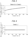
- FIGS. 3 and 4 illustrate the results.
- moisture absorption due to ambient humidity occurred before the power supply was turned on, which reduced the efficiency of the integrating sphere.
- the efficiency of the integrating sphere gradually changed as the equipment temperature rose and the integrating sphere dried out.
- FIG. 3 illustrates that moisture absorption due to ambient humidity occurred before the power supply was turned on, which reduced the efficiency of the integrating sphere.
- Example 4 moisture absorption due to the ambient humidity did not occur in Example 1 even before the power supply was turned on, and the efficiency of the integrating sphere remained constant before and after the power supply was turned on. Whereas only about 30% efficiency was obtained in Example 2 as compared to the Comparative Example, about 60% efficiency was obtained in Example 1 as compared to the Comparative Example.
- the performance of an integrating sphere is improved in that fluctuations in the efficiency of the integrating sphere due to ambient humidity are suppressed.
- stable light intensity measurement or color measurement can be achieved. Specifically, optical characteristic measurements using the integrating sphere of the present disclosure can be performed immediately, since the efficiency of the integrating sphere is stable from the moment the power is turned on. More stable measurement can also be achieved even if the ambient humidity changes, since a change in the efficiency of the integrating sphere is suppressed. For example, when the total luminous flux of a light source is measured, changes in the efficiency of the integrating sphere from measurement of the calibration light source to measurement of the light source to be measured are suppressed, thereby suppressing measurement errors.
Landscapes
- Physics & Mathematics (AREA)
- General Physics & Mathematics (AREA)
- Spectroscopy & Molecular Physics (AREA)
- Optics & Photonics (AREA)
- Chemical & Material Sciences (AREA)
- Chemical Kinetics & Catalysis (AREA)
- Photometry And Measurement Of Optical Pulse Characteristics (AREA)
Abstract
Description
- The present application claims priority to
Japanese Patent Application No. 2021-140491 filed on August 30, 2021 - The present disclosure relates to an integrating sphere.
- An integrating sphere is an optical component used to diffuse light from a light source uniformly. For example, Patent Literature (PTL) 1 discloses a total luminous flux measurement apparatus that includes an integrating sphere. Here, in the measurement of the total light intensity of a light source with directionality, the measurement must be repeated for all directions because the measured value changes depending on the direction in which the light intensity is measured. Light from a light source, even a light source with directionality such as a Light Emitting Diode (LED), for example, repeatedly diffuses in the integrating sphere. As a result, the brightness in the integrating sphere becomes uniform. Therefore, by simply measuring the brightness inside the integrating sphere once, a measured value proportional to the total light intensity emitted by the light source is obtained. Light from the light source is repeatedly scattered and reflected inside the integrating sphere to become homogeneous, however, and a portion of the light reaches the detector. The measured value is therefore attenuated according to the reflectance in the integrating sphere. The proportion of usable light among the light incident on the integrating sphere is referred to as the efficiency of the integrating sphere. When an integrating sphere of unknown efficiency is used, a calibration light source with known total luminous flux is measured, and the light intensity relative to the calibration light source is measured to determine the total luminous flux of the measurement target. Changes in the efficiency of the integrating sphere during a series of measurements using the integrating sphere would lead to measurement errors. It is therefore important to prevent fluctuations in the efficiency of the integrating sphere.
- PTL 1:
JP H07-146175 A - The efficiency of a known integrating sphere is problematic in that it depends on the dryness of the integrating sphere.
- It would be helpful to improve the accuracy of optical measurements using an integrating sphere by suppressing moisture absorption of the integrating sphere and suppressing fluctuations in the efficiency of the integrating sphere.
- An integrating sphere according to some embodiments includes a hollow member and a diffusive coating, on an inner surface of the hollow member, configured to scatter and reflect light from a light source within the hollow member to yield diffused light, wherein the diffusive coating is coated with a hydrophobic coating.
- This configuration suppresses the absorption of moisture from ambient humidity into the diffusive coating. As a result, a decrease in reflectance of the diffusive coating is suppressed, and fluctuations in the efficiency of the integrating sphere due to ambient humidity are suppressed.
- In an embodiment, the hydrophobic coating includes a single hydrophobic resin.
- This configuration suppresses the absorption of moisture from ambient humidity into the diffusive coating. As a result, a decrease in reflectance of the diffusive coating is suppressed, and fluctuations in the efficiency of the integrating sphere due to ambient humidity are suppressed.
- In the diffusive coating, particles of barium sulfate powder are generally fixed with gaps therebetween, and reflection of the light occurs at the interface between the powder and air, giving rise to diffusivity. When a hydrophobic coating consisting of only a single hydrophobic resin is applied, the hydrophobic resin penetrates between the barium sulfate powder particles and reduces the reflectivity at the interface with the barium sulfate, thus reducing the efficiency of the integrating sphere. The efficiency of the integrating sphere of the present disclosure is lower than that of an integrating sphere without a hydrophobic coating, but fluctuations are suppressed.
- In an embodiment, the hydrophobic coating includes a powder of a hydrophobic resin and a binder of a hydrophobic resin.
- As a result, light is also reflected at the interface between the hydrophobic resin powder and the hydrophobic resin binder, and the hydrophobic coating has the function of diffusing light. This increases the efficiency of the integrating sphere and suppresses fluctuations in the efficiency of the integrating sphere as compared to application of a hydrophobic coating consisting of only a single hydrophobic resin.
- In an embodiment, the powder of the hydrophobic resin is transparent at a wavelength of the light and has a particle size larger than the wavelength of the light.
- This configuration suppresses a reduction in the efficiency of the integrating sphere.
- In an embodiment, the binder of the hydrophobic resin is transparent at a wavelength of the light and has a refractive index that differs from a refractive index of the powder by 0.02 or more.
- This configuration suppresses a reduction in the efficiency of the integrating sphere.
- In an embodiment, the hydrophobic resin includes fluoropolymer, silicone resin, polypropylene, polyethylene, or polyethylene terephthalate.
- This configuration suppresses a reduction in the efficiency of the integrating sphere.
- According to the present disclosure, the moisture absorption of the integrating sphere is suppressed, and fluctuations in the efficiency of the integrating sphere are suppressed, thereby improving the accuracy of optical measurements using the integrating sphere.
- In the accompanying drawings:
-
FIG. 1 illustrates an example of applying an integrating sphere according to a Comparative Example applied to a color measurement apparatus; -
FIG. 2 illustrates an integrating sphere according to an embodiment of the present disclosure; -
FIG. 3 illustrates the relative time variation in the rate of change of the efficiency of the integrating sphere according to the Comparative Example, with the measurement start time set as 100%; and -
FIG. 4 illustrates the relative time variation in the rate of change of the efficiency of the integrating sphere according to Example 1, with the measurement start time set as 100%. - An embodiment of the present disclosure is now described with reference to the drawings. Identical reference signs in the drawings indicate identical or equivalent constituent elements.
-
FIG. 1 illustrates an example of anintegrating sphere 10 according to a Comparative Example applied to a color measurement apparatus. - The integrating
sphere 10 includes ahollow member 1, afirst opening 2 for guiding light from a light source 30 into thehollow member 1, and asecond opening 3 for guiding diffused light that was diffused within thehollow member 1 to the outside of thehollow member 1. Thefirst opening 2 is provided at the top (light source 30 side) of thehollow member 1. Thesecond opening 3 is provided at the bottom (light receiving side) of thehollow member 1. - On the inner surface of the
hollow member 1, adiffusive coating 4 is provided to scatter and reflect light from the light source 30 within thehollow member 1, thereby yielding diffused light. Thediffusive coating 4 generally includes barium sulfate powder and a binder such as polyvinyl alcohol (PVA). - The light from a light source 30 such as a white LED, for example, enters the
hollow member 1 from thefirst opening 2, is sufficiently diffused within thehollow member 1, and is emitted from thesecond opening 3 as diffused light to the outside of thehollow member 1. A portion of the diffused light emitted from thehollow member 1 is reflected by acylindrical mirror 50 arranged to surround the optical axis and strikes ameasurement target 60. Among the diffused light scattered by themeasurement target 60, the diffused light that is directed vertically upward is extracted by amirror 40 and acollimation lens 70, and the reflected intensity is measured by aspectrometer 80. The reflectance of themeasurement target 60 is measured by recording the reflection intensity of a reflective member with known reflectance in advance. Here, the diffused light emitted from the integratingsphere 10 is uniformly distributed. Themeasurement target 60 is therefore illuminated with the same intensity regardless of direction. Consequently, even if themeasurement target 60 has directional characteristics of reflectance, stable measurement is possible regardless of the installation angle of themeasurement target 60. - The PVA in the
diffusive coating 4, however, is hydrophilic and absorbs moisture from ambient humidity. The PVA that has absorbed moisture swells and ends up filling the gaps between the barium sulfate powder particles, which may reduce the reflectance of thediffusive coating 4. Even a slight reduction in the reflectance of thediffusive coating 4 significantly changes the efficiency of the integratingsphere 10, since light is repeatedly reflected within the integratingsphere 10. The efficiency of the integratingsphere 10 according to the Comparative Example thus fluctuates depending on the ambient humidity, preventing stable measurement. For example, when the total luminous flux of the light source 30 is measured, measurement error occurs if the efficiency of the integratingsphere 10 changes between measurement of the calibration light source and measurement of the light source that is themeasurement target 60. When the light source for color measurement is used, measurement error occurs if the efficiency of the integrating sphere changes between measurement of the calibration reflector and measurement of themeasurement target 60. This is due to the efficiency of the integratingsphere 10 changing as the integratingsphere 10 dries, due to heat from the light source and the apparatus, until becoming sufficiently dry. In particular, in a color measurement apparatus used to measure the color of paper during production in paper mills, a sensor may be heated and kept at a constant temperature to suppress the effects of temperature changes in the production process. In this case as well, the drying of the integratingsphere 10 progresses, and the efficiency of the integratingsphere 10 may change. To avoid these measurement errors, it has been necessary to wait for several hours until the change in the efficiency of the integratingsphere 10 subsides. - In contrast, the aforementioned problem can be solved according to the present embodiment. In other words, according to the present embodiment, fluctuations in the efficiency of the integrating sphere due to ambient humidity are suppressed. As a result, stable light intensity measurement or color measurement can be realized.
- An integrating
sphere 20 according to the present embodiment is now described with reference toFIG. 2 . - The integrating
sphere 20 includes ahollow member 1, afirst opening 2 for guiding light from a light source, and asecond opening 3 for guiding diffused light that was diffused within thehollow member 1 to the outside of thehollow member 1. Thefirst opening 2 is provided at the top (light source side) of thehollow member 1. Thesecond opening 3 is provided at the bottom (light receiving side) of thehollow member 1. However, the number of openings provided in the integratingsphere 20 is not limited to this example and may be set freely. For example, a single opening may serve as an input port and output port for light, or the light source may be installed inside the integratingsphere 20. The case in which the integratingsphere 20 includes thefirst opening 2 and thesecond opening 3 is described below in detail, but the present disclosure is not limited to this configuration. - On the inner surface of the
hollow member 1, adiffusive coating 4 is provided to scatter and reflect light from the light source within thehollow member 1, thereby yielding diffused light. - A
hydrophobic coating 5 is coated on thediffusive coating 4. In other words, thehydrophobic coating 5 is provided on thediffusive coating 4. - The
hollow member 1 is obtained by using any appropriate or known method to hollow out a metal, such as aluminum, that is easy to process and has high reflectivity so that the inner surface becomes spherical, for example. - The
diffusive coating 4 is formed by any appropriate or known spray method or the like on the metal, such as aluminum, that is the material of thehollow member 1. Thediffusive coating 4 diffuses light, entering thehollow member 1 from thefirst opening 2, within thehollow member 1. Thediffusive coating 4 can include a powder such as barium sulfate and a binder such as polyvinyl alcohol (PVA). In this case, in thediffusive coating 4, the barium sulfate or other powder is supported by the PVA or other binder. - The
hydrophobic coating 5 is applied on thediffusive coating 4. Thehydrophobic coating 5 suppresses the absorption of moisture from ambient humidity into thediffusive coating 4. As a result, a decrease in reflectance of thediffusive coating 4 is suppressed, and fluctuations in the efficiency of the integratingsphere 20 due to ambient humidity are suppressed. - The
hydrophobic coating 5 can include hydrophobic resins. The hydrophobic resin can include fluoropolymers such as polytetrafluoroethylene (PTFE), silicone resin, polypropylene, polyethylene, or polyethylene terephthalate. - The
hydrophobic coating 5 may be formed of a single hydrophobic resin. - Alternatively, the
hydrophobic coating 5 may include a hydrophobic resin powder and a hydrophobic resin binder. In this case, in thehydrophobic coating 5, the hydrophobic resin powder is supported by the hydrophobic resin binder. This prevents the hydrophobic resin powder from deeply penetrating between the barium sulfate powder particles in thediffusive coating 4 to fill the space between powder particles. A decrease in the reflectance of thediffusive coating 4 is thereby suppressed. In other words, since thehydrophobic coating 5 has a further function of diffusing light, the decrease in efficiency of the integratingsphere 20 is suppressed. - To enhance the diffusion effect, the hydrophobic resin powder is preferably transparent at the wavelength of light from the light source and preferably has a particle size larger than the wavelength of light. Specifically, the hydrophobic resin powder preferably has a particle size of 0.5 µm or larger in visible light. To enhance the diffusion effect with a limited hydrophobic coating thickness (for example, 50 µm to 1000 µm), the hydrophobic resin powder preferably has a particle size of 50 µm or less. The particle size of the hydrophobic resin powder can be appropriately sorted by a sieve having a mesh equivalent to the particle size.
- From the perspective of efficiency of the integrating sphere, the hydrophobic resin binder is preferably transparent at the wavelength of light from the light source and preferably has a refractive index that differs from the refractive index of the hydrophobic resin powder by 0.02 or more.
- The mixing ratio between the hydrophobic resin powder and the hydrophobic resin binder is preferably in a range of 0:100 to 50:50 by volume ratio, more preferably from 40:60 to 50:50, from the perspective of efficiency and hydrophobic performance of the integrating sphere as well as the fixing capability of the hydrophobic resin powder.
- The hydrophobic resin powder and hydrophobic resin binder are dispersed in a solvent such as butyl acetate and applied to the inner surface of the
hollow member 1, which is coated with thediffusive coating 4, by any appropriate or known spray method. The application amount is preferably 50 g to 1000 g (when dry) per square meter. InFIG. 2 , a clear interface is formed between thediffusive coating 4 and thehydrophobic coating 5. However, since the hydrophobic resin binder in thehydrophobic coating 5 is fixed by permeating into thediffusive coating 4, a clear interface might not be formed when thehydrophobic coating 5 is composed of a single hydrophobic resin. - In the Comparative Example, a known integrating sphere (barium sulfate powder fixed with PVA, 500 µm film thickness) was used.
- In Example 1, a hydrophobic coating including a silicone resin as a hydrophobic resin binder and PTFE as a hydrophobic resin powder was applied by the above-described spray method onto the diffusive coating in a known integrating sphere. The particle size of the hydrophobic resin powder was 20 µm. The application amount was 200 g (when dry) per square meter. The mixing ratio between the hydrophobic resin powder and the hydrophobic resin binder was 50:50 by volume ratio.
- In Example 2, a hydrophobic coating consisting of a single fluoropolymer (specifically, PTFE) was formed on a known integrating sphere.
- For each Example and the Comparative Example, the time variation in the rate of change of the efficiency of the integrating sphere was examined. The wavelength of light used for the measurements ranged from 400 nm to 680 nm, and the average light intensity was calculated.
FIGS. 3 and 4 illustrate the results. As illustrated inFIG. 3 , in the Comparative Example, moisture absorption due to ambient humidity occurred before the power supply was turned on, which reduced the efficiency of the integrating sphere. Once the power supply was turned on, the efficiency of the integrating sphere gradually changed as the equipment temperature rose and the integrating sphere dried out. In contrast, as illustrated inFIG. 4 , moisture absorption due to the ambient humidity did not occur in Example 1 even before the power supply was turned on, and the efficiency of the integrating sphere remained constant before and after the power supply was turned on. Whereas only about 30% efficiency was obtained in Example 2 as compared to the Comparative Example, about 60% efficiency was obtained in Example 1 as compared to the Comparative Example. - Although the present disclosure is based on embodiments and drawings, it is to be noted that various changes and modifications may be made by those skilled in the art based on the present disclosure. Therefore, such changes and modifications are to be understood as included within the scope of the present disclosure.
- According to the present disclosure, the performance of an integrating sphere is improved in that fluctuations in the efficiency of the integrating sphere due to ambient humidity are suppressed. Also, according to the present disclosure, stable light intensity measurement or color measurement can be achieved. Specifically, optical characteristic measurements using the integrating sphere of the present disclosure can be performed immediately, since the efficiency of the integrating sphere is stable from the moment the power is turned on. More stable measurement can also be achieved even if the ambient humidity changes, since a change in the efficiency of the integrating sphere is suppressed. For example, when the total luminous flux of a light source is measured, changes in the efficiency of the integrating sphere from measurement of the calibration light source to measurement of the light source to be measured are suppressed, thereby suppressing measurement errors. In the case of use in a light source for color measurement, changes in the efficiency of the integrating sphere from measurement of the calibration reflector to measurement of the measurement target are suppressed, thereby suppressing measurement errors. Furthermore, in an apparatus in which the integrating sphere is incorporated, fluctuations in the efficiency of the integrating sphere caused by drying of the integrating sphere, due to heat emitted by the apparatus itself and heat emitted by the light source, are suppressed, enabling stable measurement immediately after the apparatus is turned on. The scope of application of the present disclosure is not, however, limited to the disclosed examples.
Claims (6)
- An integrating sphere comprising:a hollow member; anda diffusive coating, on an inner surface of the hollow member, configured to scatter and reflect light from a light source within the hollow member to yield diffused light,wherein the diffusive coating is coated with a hydrophobic coating.
- The integrating sphere according to claim 1, wherein the hydrophobic coating includes a hydrophobic resin.
- The integrating sphere according to claim 1, wherein the hydrophobic coating includes a powder of a hydrophobic resin and a binder of a hydrophobic resin.
- The integrating sphere according to claim 3, wherein the powder of the hydrophobic resin is transparent at a wavelength of the light and has a particle size larger than the wavelength of the light.
- The integrating sphere according to claim 3 or 4, wherein the binder of the hydrophobic resin is transparent at a wavelength of the light and has a refractive index that differs from a refractive index of the powder by 0.02 or more.
- The integrating sphere according to any one of claims 2 to 5, wherein the hydrophobic resin includes fluoropolymer, silicone resin, polypropylene, polyethylene, or polyethylene terephthalate.
Applications Claiming Priority (1)
| Application Number | Priority Date | Filing Date | Title |
|---|---|---|---|
| JP2021140491A JP7632185B2 (en) | 2021-08-30 | 2021-08-30 | Integrating sphere |
Publications (2)
| Publication Number | Publication Date |
|---|---|
| EP4141394A1 true EP4141394A1 (en) | 2023-03-01 |
| EP4141394B1 EP4141394B1 (en) | 2025-12-31 |
Family
ID=83151406
Family Applications (1)
| Application Number | Title | Priority Date | Filing Date |
|---|---|---|---|
| EP22192536.5A Active EP4141394B1 (en) | 2021-08-30 | 2022-08-29 | ULBRICHTKUGEL |
Country Status (4)
| Country | Link |
|---|---|
| US (1) | US12529825B2 (en) |
| EP (1) | EP4141394B1 (en) |
| JP (2) | JP7632185B2 (en) |
| CN (1) | CN115727949B (en) |
Citations (2)
| Publication number | Priority date | Publication date | Assignee | Title |
|---|---|---|---|---|
| US20050280815A1 (en) * | 2004-02-03 | 2005-12-22 | Alan Ingleson | Method and apparatus for providing an integrating sphere |
| JP2021140491A (en) | 2020-03-05 | 2021-09-16 | セコム株式会社 | Simulator, simulation method and simulation program |
Family Cites Families (12)
| Publication number | Priority date | Publication date | Assignee | Title |
|---|---|---|---|---|
| JPH07146175A (en) | 1993-11-26 | 1995-06-06 | Matsushita Electric Ind Co Ltd | Total luminous flux measurement device |
| JP3781900B2 (en) * | 1998-07-15 | 2006-05-31 | エヌ・ティ・ティ・アドバンステクノロジ株式会社 | Water repellent coating |
| US6222623B1 (en) * | 1999-09-03 | 2001-04-24 | Mars Incorporated | Integrating light mixer |
| JP2005275015A (en) * | 2004-03-25 | 2005-10-06 | Kimoto & Co Ltd | Light diffusion plate, light guide plate, and backlight using the same |
| JP4272629B2 (en) * | 2005-02-16 | 2009-06-03 | 株式会社ユニテック | Reflective film, integrating sphere, and method of forming reflective film |
| JP2009281899A (en) * | 2008-05-23 | 2009-12-03 | Sanyo Electric Co Ltd | Optical device and optical system |
| JP5225829B2 (en) * | 2008-12-24 | 2013-07-03 | 浜松ホトニクス株式会社 | Spectrometer |
| JP2010259374A (en) * | 2009-05-07 | 2010-11-18 | Mkv Dream Co Ltd | Plant cultivation method |
| JP2016218000A (en) * | 2015-05-26 | 2016-12-22 | コニカミノルタ株式会社 | Set of integrating sphere and mask, colorimetry device and mask |
| CN105115902A (en) * | 2015-09-11 | 2015-12-02 | 深圳世绘林科技有限公司 | Spectrophotometer based on optical integrating spheres |
| JP6822660B2 (en) * | 2017-02-08 | 2021-01-27 | 株式会社オプトコム | Integrating sphere dimmer |
| JP7553235B2 (en) * | 2019-10-31 | 2024-09-18 | 株式会社きもと | Light Diffusion Film |
-
2021
- 2021-08-30 JP JP2021140491A patent/JP7632185B2/en active Active
-
2022
- 2022-08-25 CN CN202211026038.7A patent/CN115727949B/en active Active
- 2022-08-26 US US17/822,661 patent/US12529825B2/en active Active
- 2022-08-29 EP EP22192536.5A patent/EP4141394B1/en active Active
-
2024
- 2024-09-04 JP JP2024152298A patent/JP2024161219A/en not_active Withdrawn
Patent Citations (2)
| Publication number | Priority date | Publication date | Assignee | Title |
|---|---|---|---|---|
| US20050280815A1 (en) * | 2004-02-03 | 2005-12-22 | Alan Ingleson | Method and apparatus for providing an integrating sphere |
| JP2021140491A (en) | 2020-03-05 | 2021-09-16 | セコム株式会社 | Simulator, simulation method and simulation program |
Non-Patent Citations (1)
| Title |
|---|
| ANONYMOUS: "Integrating-Sphere Coating", 1 January 1975 (1975-01-01), pages B73 - 10403, XP093010794, Retrieved from the Internet <URL:https://ntrs.nasa.gov/api/citations/19730000403/downloads/19730000403.pdf> * |
Also Published As
| Publication number | Publication date |
|---|---|
| US20230062325A1 (en) | 2023-03-02 |
| EP4141394B1 (en) | 2025-12-31 |
| JP7632185B2 (en) | 2025-02-19 |
| CN115727949B (en) | 2026-05-12 |
| US12529825B2 (en) | 2026-01-20 |
| JP2023034320A (en) | 2023-03-13 |
| JP2024161219A (en) | 2024-11-15 |
| CN115727949A (en) | 2023-03-03 |
Similar Documents
| Publication | Publication Date | Title |
|---|---|---|
| US4995727A (en) | Compact diffusion light mixing box and colorimeter | |
| KR102152050B1 (en) | Optical characteristic measurement system | |
| JP5352217B2 (en) | Integrating sphere and photometric device | |
| TWI497039B (en) | Optical measurement apparatus including hemispherical optical integrator | |
| TWI443312B (en) | Integrating photometer for measuring total flux of light generated from light source to be measured, and method for measuring total flux of light through use of the same | |
| US5517315A (en) | Reflectometer employing an integrating sphere and lens-mirror concentrator | |
| US7283222B1 (en) | Optical measuring device | |
| TWI431257B (en) | The optical system for measurement and the color meter and colorimeter | |
| CN107795960B (en) | Measuring light source and measuring system for detecting reflection spectrum | |
| WO2011152082A1 (en) | Solar simulator and solar cell inspection apparatus | |
| CN103344613A (en) | Apparatus and method for measuring reflection characteristic of material | |
| Hanselaer et al. | A new integrating sphere design for spectral radiant flux determination of light-emitting diodes | |
| US12529825B2 (en) | Integrating sphere | |
| JP2010133833A (en) | Photometric device | |
| US10983050B2 (en) | Diffuse reflectance apparatus | |
| CN212133866U (en) | Double-beam photometric device capable of optimizing repeatability | |
| EP3494372A1 (en) | A photometric test system for light emitting devices | |
| JP2016218000A (en) | Set of integrating sphere and mask, colorimetry device and mask | |
| CN202599522U (en) | Spherical photometer for measuring luminous flux of LED | |
| Yevtushenko et al. | Vane-free design for star trackers and telescopes | |
| KR100986044B1 (en) | Optical output measuring device of semiconductor light emitting device | |
| CN111504464A (en) | Time division multiplexing double-beam photometric device | |
| Ohkubo | Integrating sphere theory for measuring optical radiation | |
| JP2002048713A (en) | Optical measuring device | |
| CN109738159A (en) | A uniform light source with focusing mirror integrating sphere |
Legal Events
| Date | Code | Title | Description |
|---|---|---|---|
| PUAI | Public reference made under article 153(3) epc to a published international application that has entered the european phase |
Free format text: ORIGINAL CODE: 0009012 |
|
| STAA | Information on the status of an ep patent application or granted ep patent |
Free format text: STATUS: THE APPLICATION HAS BEEN PUBLISHED |
|
| AK | Designated contracting states |
Kind code of ref document: A1 Designated state(s): AL AT BE BG CH CY CZ DE DK EE ES FI FR GB GR HR HU IE IS IT LI LT LU LV MC MK MT NL NO PL PT RO RS SE SI SK SM TR |
|
| P01 | Opt-out of the competence of the unified patent court (upc) registered |
Effective date: 20230603 |
|
| STAA | Information on the status of an ep patent application or granted ep patent |
Free format text: STATUS: REQUEST FOR EXAMINATION WAS MADE |
|
| 17P | Request for examination filed |
Effective date: 20230901 |
|
| RBV | Designated contracting states (corrected) |
Designated state(s): AL AT BE BG CH CY CZ DE DK EE ES FI FR GB GR HR HU IE IS IT LI LT LU LV MC MK MT NL NO PL PT RO RS SE SI SK SM TR |
|
| STAA | Information on the status of an ep patent application or granted ep patent |
Free format text: STATUS: EXAMINATION IS IN PROGRESS |
|
| 17Q | First examination report despatched |
Effective date: 20240717 |
|
| REG | Reference to a national code |
Ref legal event code: R079 Free format text: PREVIOUS MAIN CLASS: G01J0003020000 Ipc: G02B0005200000 Ref country code: DE Ref legal event code: R079 Ref document number: 602022027765 Country of ref document: DE Free format text: PREVIOUS MAIN CLASS: G01J0003020000 Ipc: G02B0005200000 |
|
| GRAP | Despatch of communication of intention to grant a patent |
Free format text: ORIGINAL CODE: EPIDOSNIGR1 |
|
| STAA | Information on the status of an ep patent application or granted ep patent |
Free format text: STATUS: GRANT OF PATENT IS INTENDED |
|
| RIC1 | Information provided on ipc code assigned before grant |
Ipc: G02B 5/20 20060101AFI20250707BHEP Ipc: G01J 3/02 20060101ALI20250707BHEP Ipc: G01J 3/10 20060101ALI20250707BHEP Ipc: G01J 3/50 20060101ALI20250707BHEP Ipc: G02B 1/18 20150101ALI20250707BHEP Ipc: G01J 1/04 20060101ALI20250707BHEP Ipc: G02B 5/02 20060101ALI20250707BHEP |
|
| INTG | Intention to grant announced |
Effective date: 20250722 |
|
| GRAS | Grant fee paid |
Free format text: ORIGINAL CODE: EPIDOSNIGR3 |
|
| GRAA | (expected) grant |
Free format text: ORIGINAL CODE: 0009210 |
|
| STAA | Information on the status of an ep patent application or granted ep patent |
Free format text: STATUS: THE PATENT HAS BEEN GRANTED |
|
| AK | Designated contracting states |
Kind code of ref document: B1 Designated state(s): AL AT BE BG CH CY CZ DE DK EE ES FI FR GB GR HR HU IE IS IT LI LT LU LV MC MK MT NL NO PL PT RO RS SE SI SK SM TR |
|
| REG | Reference to a national code |
Ref country code: CH Ref legal event code: F10 Free format text: ST27 STATUS EVENT CODE: U-0-0-F10-F00 (AS PROVIDED BY THE NATIONAL OFFICE) Effective date: 20251231 Ref country code: GB Ref legal event code: FG4D |
|
| REG | Reference to a national code |
Ref country code: DE Ref legal event code: R096 Ref document number: 602022027765 Country of ref document: DE |
|
| REG | Reference to a national code |
Ref country code: IE Ref legal event code: FG4D |
|
| REG | Reference to a national code |
Ref country code: LT Ref legal event code: MG9D |
|
| PG25 | Lapsed in a contracting state [announced via postgrant information from national office to epo] |
Ref country code: NO Free format text: LAPSE BECAUSE OF FAILURE TO SUBMIT A TRANSLATION OF THE DESCRIPTION OR TO PAY THE FEE WITHIN THE PRESCRIBED TIME-LIMIT Effective date: 20260331 |
|
| PG25 | Lapsed in a contracting state [announced via postgrant information from national office to epo] |
Ref country code: FI Free format text: LAPSE BECAUSE OF FAILURE TO SUBMIT A TRANSLATION OF THE DESCRIPTION OR TO PAY THE FEE WITHIN THE PRESCRIBED TIME-LIMIT Effective date: 20251231 Ref country code: HR Free format text: LAPSE BECAUSE OF FAILURE TO SUBMIT A TRANSLATION OF THE DESCRIPTION OR TO PAY THE FEE WITHIN THE PRESCRIBED TIME-LIMIT Effective date: 20251231 |
|
| PG25 | Lapsed in a contracting state [announced via postgrant information from national office to epo] |
Ref country code: RS Free format text: LAPSE BECAUSE OF FAILURE TO SUBMIT A TRANSLATION OF THE DESCRIPTION OR TO PAY THE FEE WITHIN THE PRESCRIBED TIME-LIMIT Effective date: 20260331 |
|
| PG25 | Lapsed in a contracting state [announced via postgrant information from national office to epo] |
Ref country code: LV Free format text: LAPSE BECAUSE OF FAILURE TO SUBMIT A TRANSLATION OF THE DESCRIPTION OR TO PAY THE FEE WITHIN THE PRESCRIBED TIME-LIMIT Effective date: 20251231 |
|
| PG25 | Lapsed in a contracting state [announced via postgrant information from national office to epo] |
Ref country code: BG Free format text: LAPSE BECAUSE OF FAILURE TO SUBMIT A TRANSLATION OF THE DESCRIPTION OR TO PAY THE FEE WITHIN THE PRESCRIBED TIME-LIMIT Effective date: 20251231 |
|
| REG | Reference to a national code |
Ref country code: NL Ref legal event code: MP Effective date: 20251231 |