EP4141336A1 - Air conditioner - Google Patents
Air conditioner Download PDFInfo
- Publication number
- EP4141336A1 EP4141336A1 EP20932608.1A EP20932608A EP4141336A1 EP 4141336 A1 EP4141336 A1 EP 4141336A1 EP 20932608 A EP20932608 A EP 20932608A EP 4141336 A1 EP4141336 A1 EP 4141336A1
- Authority
- EP
- European Patent Office
- Prior art keywords
- air
- housing
- conditioning apparatus
- boundary
- wall
- Prior art date
- Legal status (The legal status is an assumption and is not a legal conclusion. Google has not performed a legal analysis and makes no representation as to the accuracy of the status listed.)
- Withdrawn
Links
Images








Classifications
-
- F—MECHANICAL ENGINEERING; LIGHTING; HEATING; WEAPONS; BLASTING
- F24—HEATING; RANGES; VENTILATING
- F24F—AIR-CONDITIONING; AIR-HUMIDIFICATION; VENTILATION; USE OF AIR CURRENTS FOR SCREENING
- F24F1/00—Room units for air-conditioning, e.g. separate or self-contained units or units receiving primary air from a central station
- F24F1/0007—Indoor units, e.g. fan coil units
- F24F1/0018—Indoor units, e.g. fan coil units characterised by fans
- F24F1/0022—Centrifugal or radial fans
-
- F—MECHANICAL ENGINEERING; LIGHTING; HEATING; WEAPONS; BLASTING
- F24—HEATING; RANGES; VENTILATING
- F24F—AIR-CONDITIONING; AIR-HUMIDIFICATION; VENTILATION; USE OF AIR CURRENTS FOR SCREENING
- F24F1/00—Room units for air-conditioning, e.g. separate or self-contained units or units receiving primary air from a central station
- F24F1/0007—Indoor units, e.g. fan coil units
- F24F1/0043—Indoor units, e.g. fan coil units characterised by mounting arrangements
- F24F1/0047—Indoor units, e.g. fan coil units characterised by mounting arrangements mounted in the ceiling or at the ceiling
Definitions
- the present disclosure relates to an air-conditioning apparatus including a centrifugal air-sending device.
- Some existing air-conditioning apparatus includes, between an air inlet and an air outlet, a heat exchanger and a centrifugal air-sending device that has a scroll casing. Rotation of a fan housed in a scroll casing of such an air-conditioning apparatus causes air sucked through an inlet of the air-conditioning apparatus to flow into the fan along a bell mouth formed at a suction port of the scroll casing. The pressure of airflow discharged from the fan is increased in the scroll casing. Subsequently, the airflow is discharged from the scroll casing, then passes through a heat exchanger, and is discharged into an air-conditioning target space through an outlet of the air-conditioning apparatus.
- a scroll casing to be used in an air-conditioning apparatus is sometimes separated into two parts to contain a fan.
- the scroll casing separated into the two parts has a boundary that is located in a component forming a discharge port of the scroll casing and at which the two parts are fixed to each other and another boundary located opposite to the boundary across a suction port of the scroll casing (see, for example, Patent Literature 1).
- the air-conditioning apparatus in Patent Literature 1 further has a fixing portion located at a position in a wall surface of the scroll casing in the vicinity of each boundary.
- Patent Literature 1 Japanese Unexamined Patent Application Publication No. 2005-69177
- the present disclosure is made to solve such a problem, and an object of the present disclosure is to obtain an air-conditioning apparatus that inhibits a reduction in the amount of gas flowing into a scroll casing of a centrifugal air-sending device.
- An air-conditioning apparatus includes a centrifugal air-sending device that has a fan driven to rotate and a scroll casing that houses the fan, the scroll casing having a circumferential wall and a side wall, the circumferential wall being formed in a volute shape, the side wall having a suction port of air; a driving power supply configured to supply driving power to the fan; a heat exchanger located to face a discharge port of air, the discharge port being formed in the scroll casing; and a housing that houses the centrifugal air-sending device, the driving power supply, and the heat exchanger, the housing having a partition plate that partitions an interior of the housing into an air-sending chamber in which the fan is located and a heat-exchanging chamber in which the heat exchanger is located, the housing having a housing inlet through which air that flows into the air-sending chamber passes and a housing outlet through which air that flows out of the heat-exchanging chamber passes.
- the scroll casing has a first casing part that has a discharge part that forms the discharge port, the discharge part being fixed to the partition plate, a second casing part that has a portion of the circumferential wall that faces the housing inlet, the second casing part being fixed to the first casing part in such a manner that the second casing part is capable of being detached, and a fixing portion located in the side wall and at which the first casing part and the second casing part are fixed to each other.
- the first casing part and the second casing part are fixed to each other at a boundary.
- the boundary extends over the side wall and the circumferential wall.
- the boundary is located in a portion other than the discharge part.
- the fixing portion is located, when the fixing portion is viewed in an axial direction of a rotation axis of the fan, in an area other than an area defined by first virtual lines and a line that represents the housing inlet, the first virtual lines being virtual lines that connect opposite ends of the housing inlet and the rotation axis.
- the centrifugal air-sending device has the fixing portion at which the first casing part and the second casing part are fixed to each other.
- the fixing portion is located in the side wall.
- the fixing portion is located, when the fixing portion is viewed in the axial direction of the rotation axis of the fan, in an area other than the area defined by the first virtual lines and the line that represents the housing inlet, the first virtual lines being the virtual lines that connect the opposite ends of the housing inlet and the rotation axis.
- the fixing portion is located away from the housing inlet of the air-conditioning apparatus, and the air-conditioning apparatus is thus capable of inhibiting interference between the fixing portion and high-velocity air flowing in through the housing inlet.
- the air-conditioning apparatus inhibits separation of air flowing in a bell mouth and is thus capable of inhibiting a reduction in the amount of gas flowing into the scroll casing.
- Fig. 1 is a perspective view of a centrifugal air-sending device 1 according to Embodiment 1.
- Fig. 2 is a schematic diagram of the interior of the centrifugal air-sending device 1 according to Embodiment 1 when the centrifugal air-sending device 1 is viewed in the axial direction of a rotation axis RS.
- Fig. 3 is a schematic diagram of the exterior of the centrifugal air-sending device 1 according to Embodiment 1 when the centrifugal air-sending device 1 is viewed in the axial direction of the rotation axis RS.
- Fig. 2 does not illustrate a bell mouth 3 to illustrate the internal structure of the centrifugal air-sending device 1.
- the centrifugal air-sending device 1 is a double suction centrifugal air-sending device 1, into which air is sucked from both sides of the centrifugal air-sending device 1 in the axial direction of the rotation axis RS of a fan 2.
- the configuration of the part of the centrifugal air-sending device 1 on one surface of a main plate 2a is similar to the configuration of the part of the centrifugal air-sending device 1 on the other surface of the main plate 2a.
- the configuration of the centrifugal air-sending device 1 is described by use of Fig. 1 , and the configuration of the part opposite to the part of the centrifugal air-sending device 1 illustrated in Fig. 1 is not illustrated.
- the centrifugal air-sending device 1 is, for example, a multiblade centrifugal air-sending device 1, such as a sirocco fan and a turbo fan.
- the centrifugal air-sending device 1 has the fan 2, which is configured to generate airflow, and a scroll casing 4, which houses the fan 2.
- the fan 2 is driven to rotate by, for example, a motor (not illustrated) and forcibly sends air outward in radial directions with the centrifugal force generated by the rotation.
- the fan 2 has the main plate 2a, which has a disk shape, and a plurality of blades 2d, which are installed on a peripheral portion 2a1 of the main plate 2a.
- the main plate 2a may have any shape, such as a polygonal shape, other than a disk shape as long as the main plate 2a has a plate-like shape.
- An axial portion 2b, to which the motor (not illustrated) is connected, is located at the center of the main plate 2a. The main plate 2a is driven to rotate by the motor via the axial portion 2b.
- the blades 2d are located on the circumference around the axial portion 2b.
- the base ends of the blades 2d are fixed to the main plate 2a.
- the blades 2d are located on both sides of the main plate 2a in the axial direction of the rotation axis RS of the fan 2.
- the blades 2d are located on the peripheral portion 2a1 of the main plate 2a with certain spaces between the blades 2d.
- the blades 2d each have, for example, a curved rectangular plate-like shape and are each installed to extend in a radial direction or to be inclined at a predetermined angle to a radial direction.
- the blades 2d are each formed into a two-dimensional blade in which the same sectional shape is continuous in the axial direction of the rotation axis RS but may be each formed into a three-dimensional blade having a twisted shape.
- the blades 2d are located to stand substantially perpendicularly to the main plate 2a, but the configuration of the blades 2d is not limited to this description.
- the blades 2d may be located to be inclined to a direction perpendicular to the main plate 2a.
- the fan 2 has side plates (not illustrated) that each have an annular shape and that are each located at the corresponding ends of the blades 2d in the axial direction of the rotation axis RS.
- the end of each of the blades 2d to which the side plate is attached is one end opposite to the other end of the blade 2d connected to the main plate 2a.
- the side plate maintains the positional relationship between the tips of the blades 2d and reinforces the blades 2d by being connected to the blades 2d.
- the fan 2 has a cylindrical shape formed by the blades 2d located on the main plate 2a. At respective ends of the blades 2d opposite to the main plate 2a in the axial direction of the rotation axis RS, the fan 2 has suction ports 2e for allowing gas to flow through into the spaces defined by the main plate 2a and the blades 2d.
- the blades 2d are located at each side of the main plate 2a, and the suction ports 2e are formed at each side of the main plate 2a.
- the fan 2 is driven to rotate around the rotation axis RS by driving the motor (not illustrated).
- gas outside the centrifugal air-sending device 1 flows along bell mouths 3 and is sucked into the spaces defined by the main plate 2a and the blades 2d through suction ports 5, which are each formed in the scroll casing 4, and the suction ports 2e of the fan 2.
- the air sucked into the spaces defined by the main plate 2a and the blades 2d is then sent outward in a radial direction through a space between each blade 2d and the corresponding adjacent blade 2d.
- the scroll casing 4 houses the fan 2 in its inside.
- the scroll casing 4 rectifies the flow of air blown out of the fan 2.
- the scroll casing 4 is made of a resin, but the material for the scroll casing 4 is not limited to such a resin.
- the scroll casing 4 has a scroll part 41 and a discharge part 42.
- the scroll part 41 defines an air passage in which the dynamic pressure of airflow generated by the fan 2 is converted into a static pressure.
- the scroll part 41 has side walls 4a, which surround the fan 2 in the axial direction of the rotation axis RS of the axial portion 2b included in the fan 2, and a circumferential wall 4c, which surrounds the fan 2 in radial directions from the rotation axis RS.
- the side walls 4a have the respective suction ports 5 through which air is let in.
- the scroll part 41 has a tongue portion 43, which has a curved surface between the discharge part 42 and an inner end portion 41a of the circumferential wall 4c and which is a restriction portion required for blowing out, in a centrifugal direction, the air that has flowed in through the suction ports 5 and increasing the air pressure.
- a radial direction from the rotation axis RS means a direction perpendicular to the rotation axis RS.
- the internal space of the scroll part 41 defined by the circumferential wall 4c and the side walls 4a is a space in which the air that has blown out of the fan 2 flows along the circumferential wall 4c.
- the side wall 4a is located at each side of the fan 2 in the axial direction of the rotation axis RS of the fan 2. As illustrated in Figs. 1 and 3 , the side walls 4a of the scroll casing 4 have the respective suction ports 5 for letting air in in such a manner that air is allowed to flow between the fan 2 and the outside of the scroll casing 4.
- the suction ports 5 each have a circular shape.
- the fan 2 is located in such a manner that the center of each of the suction ports 5 substantially coincides with the center of the axial portion 2b of the fan 2.
- the shape of the suction port 5 is not limited to a circular shape and may be a different shape such as an oval shape.
- the scroll casing 4 of the centrifugal air-sending device 1 is a double suction casing having the side wall 4a having the suction port 5 at each side of the main plate 2a in the axial direction of the rotation axis RS of the fan 2.
- the scroll casing 4 has two side walls 4a, and the two side walls 4a are located to face each other.
- the scroll casing 4 has, as the side walls 4a, a first side wall 4a1 and a second side wall 4a2.
- the first side wall 4a1 extends along a first end 4c11, which is one end of the circumferential wall 4c in the axial direction of the rotation axis RS.
- the second side wall 4a2 extends along a second end 4c12, which is the other end of the circumferential wall 4c in the axial direction of the rotation axis RS.
- the first side wall 4a1 has the suction port 5 facing one surface of the main plate 2a.
- the second side wall 4a2 has the suction port 5 facing the other surface of the main plate 2a.
- the suction ports 5 of air located in the respective side walls 4a are each formed by the bell mouth 3.
- the bell mouths 3 rectify the flow of gas to be sucked into the fan 2 and allow the gas to flow through into the suction ports 2e of the fan 2.
- the bell mouths 3 are each formed in such a manner that the opening diameter is gradually reduced from the outside toward the inside of the scroll casing 4. With the side walls 4a having this configuration, air in the vicinity of the suction ports 5 flows smoothly along the bell mouths 3 and efficiently into the fan 2 through the suction ports 5.
- the circumferential wall 4c is a wall located between the side walls 4a facing each other and has a curved surface in a rotation direction R of the fan 2.
- the circumferential wall 4c guides, along the curved wall surface, airflow generated by the fan 2 to a discharge port 42a via the scroll part 41.
- the circumferential wall 4c is located parallel to the axial direction of the rotation axis RS of the fan 2 to surround the fan 2.
- the circumferential wall 4c may be inclined to the axial direction of the rotation axis RS of the fan 2 and is not limited to the circumferential wall 4c located parallel to the axial direction of the rotation axis RS.
- the circumferential wall 4c surrounds the fan 2 in radial directions from the rotation axis RS and has an inner circumferential surface facing the blades 2d.
- the circumferential wall 4c faces the air discharge sides of the blades 2d of the fan 2.
- the circumferential wall 4c is located to extend from the inner end portion 41a located at the boundary between the circumferential wall 4c and the tongue portion 43 to an outer end portion 41b located at the boundary between the scroll part 41 and the discharge part 42 away from the tongue portion 43 in the rotation direction R of the fan 2.
- the inner end portion 41a is an end portion of the circumferential wall 4c having the curved surface, the end portion being upstream for airflow generated by rotation of the fan 2.
- the outer end portion 41b is an end portion of the circumferential wall 4c having the curved surface, the end portion being downstream for airflow generated by rotation of the fan 2.
- the circumferential wall 4c has a volute shape in the rotation direction R.
- a volute shape include volute shapes by use of a logarithmic spiral, an Archimedean spiral, and an involute curve.
- the inner circumferential surface of the circumferential wall 4c is a surface smoothly curved in the circumferential direction of the fan 2 from the inner end portion 41a, which is an inner end of the volute shape, to the outer end portion 41b, which is an outer end of the volute shape.
- the discharge part 42 forms the discharge port 42a, through which the airflow that has been generated by the fan 2 and that has passed through the scroll part 41 is discharged.
- the discharge part 42 is made of a hollow pipe whose section orthogonal to a direction in which air flows along the circumferential wall 4c has a rectangular shape.
- the sectional shape of the discharge part 42 is not limited to a rectangular shape.
- the discharge part 42 defines a passage for guiding, to be discharged to the outside of the scroll casing 4, the air that flows between the circumferential wall 4c and the fan 2 after being sent out of the fan 2.
- the discharge part 42 has an extended plate 42b, a diffuser plate 42c, a portion of the first side wall 4a1, and a portion of the second side wall 4a2.
- the extended plate 42b is a plate-like portion integrally formed with the circumferential wall 4c and that extends from the outer end portion 41b of the circumferential wall 4c.
- the diffuser plate 42c is a plate-like portion that is integrally formed with the tongue portion 43 of the scroll casing 4 and that is located to face the extended plate 42b.
- the diffuser plate 42c is formed to have a predetermined angle with the extended plate 42b in such a manner that the sectional area of the passage increases gradually in the direction in which air flows in the discharge part 42.
- the extended plate 42b and the diffuser plate 42c are each formed between the first side wall 4a1 and the second side wall 4a2.
- the discharge part 42 has the passage whose section has a rectangular shape and that is defined by the extended plate 42b, the diffuser plate 42c, the first side wall 4a1, and the second side wall 4a2.
- the scroll casing 4 has the tongue portion 43 between the diffuser plate 42c of the discharge part 42 and the inner end portion 41a of the circumferential wall 4c.
- the tongue portion 43 is formed with a predetermined curvature radius.
- the circumferential wall 4c is smoothly continuous with the diffuser plate 42c via the tongue portion 43.
- the tongue portion 43 inhibits air from flowing from the outer end into the inner end of the volute-shaped passage formed in the scroll casing 4.
- the tongue portion 43 is located in an upstream section of the air passage and has a function of separating air flowing in the rotation direction R of the fan 2 and air flowing in the discharge direction from a downstream section of the air passage toward the discharge port 42a.
- the static pressure of air flowing into the discharge part 42 increases during the air passing through the scroll casing 4 and becomes higher than the pressure in the scroll casing 4.
- the tongue portion 43 has a function of separating areas different from each other in pressure as described above.
- the scroll casing 4 has a first casing part 45, a second casing part 46, and fixing portions 20.
- the scroll casing 4 is allowed to be separated into the first casing part 45 and the second casing part 46. That is, the scroll casing 4 is formed by combining the first casing part 45 and the second casing part 46.
- the first casing part 45 has a portion of the scroll part 41 and the discharge part 42, which forms the discharge port 42a.
- the first casing part 45 has a portion of the circumferential wall 4c and a portion of each of the side walls 4a.
- the first casing part 45 has a portion of each of the bell mouths 3.
- the second casing part 46 is formed by a portion of the scroll part 41.
- the second casing part 46 has a portion of the circumferential wall 4c and a portion of each of the side walls 4a.
- the second casing part 46 has a portion of each of the bell mouths 3.
- the second casing part 46 is fixed to the first casing part 45 in such a manner that the second casing part 46 is capable of being detached.
- the fan 2 is exposed by detaching the second casing part 46 from the first casing part 45.
- the bell mouths 3, each of which has an annular shape when viewed parallelly to the axial direction of the rotation axis RS, are each formed by combining the first casing part 45 and the second casing part 46. That is, when viewed parallelly to the axial direction of the rotation axis RS, the suction ports 5 of the scroll casing 4 are each formed by combining the first casing part 45 and the second casing part 46.
- the scroll casing 4 contains the fan 2 and thus has boundaries 60 for convenience of assembly.
- the boundaries 60 at which the first casing part 45 and the second casing part 46 are fixed to each other, extend over the side walls 4a and the circumferential wall 4c of the scroll casing 4.
- the boundaries 60 are each located in a portion other than the discharge part 42. More specifically, the boundaries 60 are each located in an area other than an area SA located between the inner end portion 41a, which is an inner end of the scroll casing 4, and the discharge port 42a in the direction in which air flows in the discharge part 42.
- the area SA is, for example, an area between an edge 42d and a boundary line 42e when viewed in a direction parallel to the axial direction of the rotation axis RS of the fan 2.
- the edge 42d is an end edge of each of the side walls 4a, and the end edges are each included in the discharge port 42a.
- the boundary line 42e is a virtual line that includes the inner end portion 41a and that is parallel to the edge 42d.
- the parallel relationship between the boundary line 42e and the edge 42d includes a completely parallel relationship between the boundary line 42e and the edge 42d and a substantially parallel relationship between the boundary line 42e and the edge 42d.
- the boundaries 60 include a first boundary 61, which is located upstream for airflow in a direction in which air flows in the circumferential wall 4c, the direction being represented by airflow AR illustrated in Fig. 2 , and a second boundary 62, which is located downstream for airflow in the direction in which air flows in the circumferential wall 4c.
- the first casing part 45 and the second casing part 46 of the scroll casing 4 are fixed to each other at the two boundaries 60, which are the first boundary 61 and the second boundary 62.
- the scroll casing 4 is separated into the two components, which are the first casing part 45 and the second casing part 46, at the two boundaries 60, which are the first boundary 61 and the second boundary 62.
- the fixing portions 20 are located at the boundaries 60 of the scroll casing 4.
- the fixing portions 20 are used to fix the first casing part 45 and the second casing part 46 to each other.
- the fixing portions 20 are located in the side wall 4a of the scroll casing 4.
- the fixing portions 20 include first fixing portions 20A and second fixing portions 20B.
- the first fixing portions 20A are each located at the first boundary 61.
- the second fixing portions 20B are each located at the second boundary 62. That is, the first fixing portion 20A is located upstream, for airflow, of the second fixing portion 20B in the direction in which air flows in the circumferential wall 4c, the direction being represented by the airflow AR illustrated in Fig. 2 , and the second fixing portion 20B is located downstream, for airflow, of the first fixing portion 20A in the direction in which air flows in the circumferential wall 4c.
- the fixing portion 20 is formed by fitting and joining a first engagement portion 21, which is located in the first casing part 45, and a second engagement portion 22, which is located in the second casing part 46, to each other.
- the fixing portion 20 may be formed by screwing together the first engagement portion 21, which is located in the first casing part 45, and the second engagement portion 22, which is located in the second casing part 46.
- the configuration of the fixing portion 20 is not limited to these configurations.
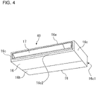
- Fig. 4 is a perspective view schematically illustrating an example of the air-conditioning apparatus 40 according to Embodiment 1.
- Fig. 5 is a schematic diagram illustrating an example of the internal configuration of the air-conditioning apparatus 40 according to Embodiment 1.
- Fig. 6 is a side view schematically illustrating an example of the internal configuration of the air-conditioning apparatus 40 according to Embodiment 1.
- Fig. 5 does not illustrate top components such as a top portion 16a to illustrate the internal configuration of the air-conditioning apparatus 40.
- the air-conditioning apparatus 40 including the centrifugal air-sending devices 1 will be described by use of Figs. 4 to 6 .
- the air-conditioning apparatus 40 is an apparatus that is configured to condition air in an air-conditioning target space and that is configured to control the temperature and the humidity of sucked air to discharge the air into an air-conditioning target space.
- the air-conditioning apparatus 40 is a ceiling suspended apparatus, which is suspended from a ceiling, but is not limited to such a ceiling suspended apparatus.
- the air-conditioning apparatus 40 includes the centrifugal air-sending devices 1, a driving power supply 6, which is configured to supply driving power to the fan 2 of each of the centrifugal air-sending devices 1, and a heat exchanger 10, which is located to face the discharge ports 42a of air, the discharge port 42a being formed in each of the scroll casings 4 of the centrifugal air-sending devices 1.
- the air-conditioning apparatus 40 includes a housing 16, which houses, in its inside, the centrifugal air-sending devices 1, the driving power supply 6, and the heat exchanger 10 and which is installed on a ceiling of an air-conditioning target space.
- the air-conditioning apparatus 40 may include a heat-insulating material 13 in a heat-exchanging chamber 26, which will be described later.
- the housing 16 has a box shape and has the top portion 16a, a bottom portion 16b, and side portions 16c to form a cuboid shape.
- the shape of the housing 16 is not limited to a cuboid shape and may be a different shape such as a cylindrical shape, a rectangular column shape, a circular cone shape, a shape having a plurality of corners, and a shape having a plurality of curved surfaces.
- the housing 16 has, as one of the side portions 16c, an inlet wall 16c1 having a housing inlet 18.
- a filter for removing dust in air may be located at the housing inlet 18.
- the housing 16 has, as one of the side portions 16c, an outlet wall 16c2 having a housing outlet 17.
- the inlet wall 16c1 and the outlet wall 16c2 of the housing 16 form side wall surfaces located opposite to each other across the heat exchanger 10 and the centrifugal air-sending devices 1.
- the housing inlet 18 is only required to be located at a position perpendicular to the axial direction of the rotation axis RS of each of the centrifugal air-sending devices 1.
- the bottom portion 16b may have the housing inlet 18.
- An arrow IR illustrated in Fig. 6 represents air to be sucked into the housing inlet 18.
- An arrow OR illustrated in Fig. 6 represents air to be blown out of the housing outlet 17.
- the housing outlet 17 and the housing inlet 18 each have a rectangular shape.
- Each shape of the housing outlet 17 and the housing inlet 18 is not limited to a rectangular shape and may be a different shape such as a circular shape and an oval shape.
- a partition plate 19 partitions the internal space of the housing 16 into the air-sending chamber 25, which is a space located at the suction sides of the scroll casings 4, and the heat-exchanging chamber 26, which is a space located at the discharge sides of the scroll casings 4. That is, the partition plate 19 partitions the internal space of the housing 16 into the air-sending chamber 25, in which the fans 2 are located, and the heat-exchanging chamber 26, in which the heat exchanger 10 is located.
- the housing 16 houses, in its inside, the driving power supply 6, the two centrifugal air-sending devices 1, and the heat exchanger 10.
- the driving power supply 6 is, for example, a motor.
- the driving power supply 6 is supported by a motor support 9a, which is fixed to the top portion 16a of the housing 16.
- the driving power supply 6 has an output shaft 6a.
- the output shaft 6a is located to extend parallel to the inlet wall 16c1 having the housing inlet 18 and the outlet wall 16c2 having the housing outlet 17.
- the centrifugal air-sending devices 1 each have the fan 2 and the scroll casing 4 having the bell mouths 3. As illustrated in Figs. 5 and 6 , the discharge part 42 of the scroll casing 4 of the centrifugal air-sending device 1 is fixed to the partition plate 19.
- the fan 2 of each of the two centrifugal air-sending devices 1 of the air-conditioning apparatus 40 is attached to the output shaft 6a.
- the centrifugal air-sending device 1 having the fan 2 forms airflow to be sucked into the housing 16 from the housing inlet 18 and blown out into an air-conditioning target space from the housing outlet 17.
- the number of the centrifugal air-sending devices 1 to be located in the housing 16 is not limited to two and may be one or three or more.
- the second casing part 46 of the scroll casing 4 has a portion of the circumferential wall 4c facing the housing inlet 18.
- Other components are not located between the housing inlet 18 and the portion of the circumferential wall 4c facing the housing inlet 18.
- the portion of the circumferential wall 4c and the housing inlet 18 directly face each other.
- first virtual lines CL When viewed in the axial direction of the rotation axis RS, virtual lines that connect opposite ends 18a and 18b of the housing inlet 18 and the rotation axis RS are defined as first virtual lines CL.
- the end 18a When viewed in the axial direction of the rotation axis RS, the end 18a is a top end of the housing inlet 18, and the end 18b is a bottom end of the housing inlet 18.
- a substantially triangular area defined by the first virtual lines CL and a line that represents the housing inlet 18 is defined as an area SB.
- the fixing portions 20 of the centrifugal air-sending device 1 are each located, when viewed in the axial direction of the rotation axis RS of the fan 2, in an area other than the area SB defined by the first virtual lines CL and the line that represents the housing inlet 18.
- the first fixing portion 20A is located opposite to the second fixing portion 20B across the rotation axis RS.
- the second fixing portion 20B is located opposite to the first fixing portion 20A across the rotation axis RS.
- the positional relationship between the first fixing portion 20A and the second fixing portion 20B is not limited to this relationship.
- first boundary 61 is located opposite to the second boundary 62 across the rotation axis RS.
- the second boundary 62 is located opposite to the first boundary 61 across the rotation axis RS.
- the positional relationship between the first boundary 61 and the second boundary 62 is not limited to this relationship.
- the heat exchanger 10 is located to face the discharge port 42a of the centrifugal air-sending device 1.
- the heat exchanger 10 is located in an air passage in the housing 16 for air discharged by the centrifugal air-sending device 1.
- the heat exchanger 10 adjusts the temperature of air sucked into the housing 16 through the housing inlet 18 and to be blown out into an air-conditioning target space through the housing outlet 17.
- a heat exchanger having a known structure is applicable to the heat exchanger 10.
- the air-conditioning apparatus 40 is configured in such a manner that the housing inlet 18, the scroll casings 4 of the centrifugal air-sending devices 1, the heat exchanger 10, and the housing outlet 17 are arranged in the named order in a direction from the housing inlet 18 toward the housing outlet 17 of the air-conditioning apparatus 40. In the case of such a ceiling suspended air-conditioning apparatus 40, these components are arranged in a horizontal direction.
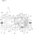
- Fig. 7 is a side view schematically illustrating the internal configuration of a modification example of the air-conditioning apparatus 40 according to Embodiment 1.
- the area SA is described as an area between the edge 42d and the boundary line 42e when viewed in the direction parallel to the axial direction of the rotation axis RS of the fan 2.
- the area SA is not limited to this area.
- a vertical virtual line that passes through the inner end portion 41a of the scroll casing 4 and that connects the top portion 16a, which forms the top surface of the housing 16, and the bottom portion 16b, which forms the bottom surface of the housing 16, is defined as a virtual line FL.
- the area SA may be an area of the scroll casing 4 defined by the virtual line FL and a line that represents the discharge port 42a.
- the pressure of the air blown out of the fans 2 increases while the air passes through the scroll casings 4.
- the air whose pressure is increased is blown out through the discharge ports 42a of the scroll casings 4 and is then supplied to the heat exchanger 10.
- the air supplied to the heat exchanger 10 is subjected to heat exchange with a heat exchange medium such as refrigerant flowing in the heat exchanger 10 while the air passes through the heat exchanger 10, and the temperature and the humidity of the air are adjusted.
- the air that has passed through the heat exchanger 10 is blown out into the air-conditioning target space through the housing outlet 17.
- the centrifugal air-sending device 1 has the fixing portions 20, at which the first casing part 45 and the second casing part 46 are fixed to each other.
- the fixing portions 20 are located in the side wall 4a.
- the fixing portions 20 are each located, when viewed in the axial direction of the rotation axis RS of the fan 2, in an area other than the area SB defined by the first virtual lines CL and the line that represents the housing inlet 18, the first virtual lines CL being the virtual lines that connect the opposite ends of the housing inlet 18 and the rotation axis RS.
- the fixing portions 20 are located away from the housing inlet 18 of the air-conditioning apparatus 40, and the air-conditioning apparatus 40 is thus capable of inhibiting interference between the fixing portions 20 and high-velocity air flowing in through the housing inlet 18.
- the air-conditioning apparatus 40 inhibits separation of air flowing in the bell mouths 3 and is thus capable of inhibiting a reduction in the amount of gas flowing into the scroll casing 4.
- Fig. 8 is a schematic diagram of a centrifugal air-sending device 1L according to a comparative example when the centrifugal air-sending device 1L is viewed in the axial direction of the rotation axis RS.
- Fig. 9 is a schematic diagram of the separated centrifugal air-sending device 1L according to the comparative example.
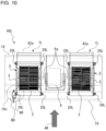
- Fig. 10 is a schematic diagram illustrating an example of the internal configuration of an air-conditioning apparatus 40L according to the comparative example. The centrifugal air-sending device 1L and the air-conditioning apparatus 40L according to the comparative example will be described by use of Figs. 8 to 10 .
- the air-conditioning apparatus 40L includes the centrifugal air-sending devices 1L.
- a scroll casing 4L of each of the centrifugal air-sending devices 1L is separated into two parts, which are a lower casing part 47L and an upper casing part 48L, to contain the fan 2.
- the scroll casing 4L separated into the two parts, which are the lower casing part 47L and the upper casing part 48L has a boundary 60L, which is located in a discharge part 42L forming the discharge port 42a of the scroll casing 4L and at which the two parts are fixed to each other.
- the scroll casing 4L has another boundary 60L, which is located opposite to a boundary 60 of the discharge part 42L across the suction port 5 of the scroll casing 4L.
- the centrifugal air-sending device 1L To fix the two separated parts, which are the lower casing part 47L and the upper casing part 48L, to each other, the centrifugal air-sending device 1L according to the comparative example has a fixing portion 20L located at a position in a side wall surface of the scroll casing 4L in the vicinity of each boundary 60L.
- airflow AR and the fixing portion 20L located and facing the housing inlet 18 of the air-conditioning apparatus 40L may interfere with each other. Such interference between the airflow AR and the fixing portion 20L located and facing the housing inlet 18 of the air-conditioning apparatus 40L may cause separation of air flowing in a bell mouth and thus may reduce the amount of gas flowing into the scroll casing 4L.
- the air-conditioning apparatus 40 has the configuration described above in which the fixing portions 20 are located away from the housing inlet 18 of the air-conditioning apparatus 40 and is thus capable of inhibiting interference between the fixing portions 20 and high-velocity air flowing in through the housing inlet 18.
- the air-conditioning apparatus 40 inhibits separation of air flowing in the bell mouths 3 and is thus capable of inhibiting a reduction in the amount of gas flowing into the scroll casings 4.
- interference between the airflow AR and the fixing portion 20L located and facing the housing inlet 18 of the air-conditioning apparatus 40L according to the comparative example may cause noise and thus may increase noise emitted from the air-conditioning apparatus 40L.
- the air-conditioning apparatus 40 according to Embodiment 1 has the configuration described above in which the fixing portions 20 are located away from the housing inlet 18 of the air-conditioning apparatus 40 and is thus capable of inhibiting interference between the fixing portions 20 and high-velocity air flowing in through the housing inlet 18.
- the air-conditioning apparatus 40 is capable of inhibiting generation of noise caused by interference between the fixing portions 20 and high-velocity air flowing in through the housing inlet 18 and is thus capable of reducing noise emitted from the air-conditioning apparatus 40 compared with the air-conditioning apparatus 40L according to the comparative example.
- the pressure of air flowing in a scroll casing increases while the air moves toward a discharge port of the scroll casing.
- the boundary 60L is located in the discharge part 42L forming the discharge port 42a of the scroll casing 4L.
- high-pressure air whose pressure is increased is prone to leak through the boundary 60L of the discharge part 42L.
- the boundaries 60 are each located in a portion other than the discharge part 42. Since the boundaries 60 are not located in the discharge part 42, through which high-pressure air passes, the air-conditioning apparatus 40 according to Embodiment 1 is capable of inhibiting air leakage through the boundaries 60 compared with the air-conditioning apparatus 40L according to the comparative example.
- the boundaries 60 are each located in an area other than the area SA located between the inner end portion 41a, which is the inner end of the scroll casing 4, and the discharge port 42a in the direction in which air flows in the discharge part 42. That is, the boundaries 60 of the air-conditioning apparatus 40 according to Embodiment 1 are not located in the discharge part 42. Since the boundaries 60 are not located in the discharge part 42, through which high-pressure air passes, the air-conditioning apparatus 40 according to Embodiment 1 is capable of inhibiting air leakage through the boundaries 60 compared with the air-conditioning apparatus 40L according to the comparative example.
- the inlet wall 16c1 having the housing inlet 18 and the outlet wall 16c2 having the housing outlet 17 of the air-conditioning apparatus 40 form the side wall surfaces located opposite to each other across the heat exchanger 10 and the centrifugal air-sending devices 1.
- the air-conditioning apparatus 40 is allowed to be configured in such a manner that the inlet wall 16c1, the centrifugal air-sending devices 1, the heat exchanger 10, and the outlet wall 16c2 are arranged in the horizontal direction. It is thus possible to make, with a simple form, the air passage from the housing inlet 18 to the housing outlet 17. Furthermore, since these components are allowed to be arranged in the horizontal direction, the air-conditioning apparatus 40 is usable as, for example, a ceiling suspended air-conditioning apparatus.
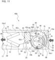
- Fig. 11 is a side view schematically illustrating an example of the internal configuration of an air-conditioning apparatus 40A according to Embodiment 2. Parts having the same configurations as those of the air-conditioning apparatus 40 illustrated in Figs. 1 to 10 have the same reference signs, and their descriptions are omitted. The positions of the boundaries 60 and the fixing portions 20 of a centrifugal air-sending device 1A housed in the air-conditioning apparatus 40A according to Embodiment 2 are further specified. Thus, the configurations in which the boundaries 60 and the fixing portions 20 of the centrifugal air-sending device 1A are located will be mainly described below by use of Fig. 11 .
- the configurations of the air-conditioning apparatus 40A and the centrifugal air-sending device 1A according to Embodiment 2 are the same as the respective configurations of the air-conditioning apparatus 40 and the centrifugal air-sending device 1 according to Embodiment 1 unless otherwise described.
- the boundaries 60 of the centrifugal air-sending device 1A include the first boundary 61, which is located upstream in the direction in which air flows in the circumferential wall 4c, and the second boundary 62, which is located downstream in the direction in which air flows in the circumferential wall 4c. Between the housing inlet 18 and the housing outlet 17 of the air-conditioning apparatus 40A, one of the first boundary 61 and the second boundary 62 is located closer to the housing outlet 17 than is the other of the first boundary 61 and the second boundary 62. That is, unlike Embodiment 1, the first boundary 61 and the second boundary 62 of the centrifugal air-sending device 1A are not located in line with each other but are located to be shifted from each other in a left-right direction.
- the fixing portions 20 are located at the boundaries 60 of the air-conditioning apparatus 40A. Thus, between the housing inlet 18 and the housing outlet 17 of the air-conditioning apparatus 40A, one of the first fixing portion 20A and the second fixing portion 20B is located closer to the housing outlet 17 than is the other of the first fixing portion 20A and the second fixing portion 20B. That is, the first fixing portion 20A and the second fixing portion 20B of the centrifugal air-sending device 1Aare located to be shifted from each other in the left-right direction.
- a portion of the first boundary 61 located at the inner edge of the suction port 5 is defined as a first inner edge 5a
- a portion of the second boundary 62 located at the inner edge of the suction port 5 is defined as a second inner edge 5b.
- a second virtual line TL which is a virtual line that connects the first inner edge 5a and the second inner edge 5b, may be located closer to the housing outlet 17 than is the rotation axis RS.
- the air-conditioning apparatus 40A is the same, as the air-conditioning apparatus 40 in Embodiment 1, in the positions at which the boundaries 60 are located and the positions at which the fixing portions 20 are located and thus achieves effects similar to those of the air-conditioning apparatus 40.
- one of the first boundary 61 and the second boundary 62 is located closer to the housing outlet 17 than is the other of the first boundary 61 and the second boundary 62.
- one of the first fixing portion 20A and the second fixing portion 20B is located away from the housing inlet 18.
- the air-conditioning apparatus 40A the velocity of airflow that interferes with the fixing portions 20 located away from the housing inlet 18 is low.
- the air-conditioning apparatus 40A is capable of inhibiting a reduction in the amount of gas flowing into the scroll casing 4.
- the air-conditioning apparatus 40A is capable of inhibiting generation of noise caused by interference between the airflow and the fixing portions 20 and is thus capable of reducing noise emitted from the air-conditioning apparatus 40A compared with the air-conditioning apparatus 40L.
- the centrifugal air-sending device 1A is formed in consideration of the balance between the surface area of the first casing part 45 and the surface area of the second casing part 46.
- the air-conditioning apparatus 40A has the configuration described above, it is possible to maintain a sufficient distance between the housing inlet 18 and each fixing portion 20 while balancing the surface area of the first casing part 45 and the surface area of the second casing part 46 with each other.
- the second virtual line TL may be located closer to the housing outlet 17 than is the rotation axis RS.
- both the first fixing portion 20A and the second fixing portion 20B are located further away from the housing inlet 18 than is the first fixing portion 20A and the second fixing portion 20B located opposite to each other across the rotation axis RS.
- the velocity of airflow that interferes with the fixing portions 20 is low.
- the air-conditioning apparatus 40A is capable of inhibiting a reduction in the amount of gas flowing into the scroll casing 4.
- the air-conditioning apparatus 40A is capable of inhibiting generation of noise caused by interference between the airflow and the fixing portions 20 and is thus capable of reducing noise emitted from the air-conditioning apparatus 40A compared with the air-conditioning apparatus 40L.
- Fig. 12 is a side view schematically illustrating an example of the internal configuration of an air-conditioning apparatus 40B according to Embodiment 3. Parts having the same configurations as those of the air-conditioning apparatus 40 and other apparatuses illustrated in Figs. 1 to 11 have the same reference signs, and their descriptions are omitted.
- the configuration of the boundaries 60 of a centrifugal air-sending device 1B housed in the air-conditioning apparatus 40B according to Embodiment 3 is further specified.
- the configuration of the boundaries 60 of the centrifugal air-sending device 1B will be mainly described below by use of Fig. 12 .
- the configurations of the air-conditioning apparatus 40B and the centrifugal air-sending device 1B according to Embodiment 3 are the same as the respective configurations of the air-conditioning apparatus 40 and the centrifugal air-sending device 1 according to Embodiment 1 unless otherwise described.
- the centrifugal air-sending device 1B has a scroll casing 4B.
- the circumferential wall 4c of the scroll casing 4B has flat portions 65, each of which is a portion of the wall formed in a flat shape.
- the flat portion 65 is formed in a flat shape and located in a portion of the circumferential wall 4c formed in a volute shape. When viewed in the axial direction of the rotation axis RS of the fan 2, the flat portion 65 is formed in a linear shape.
- the scroll casing 4B is formed in such a manner that the boundary 60 separates the flat portion 65. That is, the flat portion 65 is located at the boundary 60.
- the flat portion 65 located at the first boundary 61 and the flat portion 65 located at the second boundary 62 may be located parallel to each other.
- the configuration of the scroll casing 4 is not limited to such a configuration in which the flat portion 65 located at the first boundary 61 and the flat portion 65 located at the second boundary 62 are located parallel to each other.
- the air-conditioning apparatus 40B is the same, as the air-conditioning apparatus 40 in Embodiment 1, in the positions at which the boundaries 60 are located and the positions at which the fixing portions 20 are located and thus achieves effects similar to those of the air-conditioning apparatus 40.
- the scroll casing 4B is formed in such a manner that the boundary 60 separates the flat portion 65.
- the boundary 60 provided with the flat portion 65 facilitates removal of the first casing part 45 and the second casing part 46 from a mold and thus facilitates production of the air-conditioning apparatus 40B.
- the flat portion 65 located at the first boundary 61 and the flat portion 65 located at the second boundary 62 are located parallel to each other.
- the first casing part 45 and the second casing part 46 are each made of a resin and the flat portion 65 located at the first boundary 61 and the flat portion 65 located at the second boundary 62 are located parallel to each other, removal of the first casing part 45 and the second casing part 46 from a mold is further facilitated and production of the air-conditioning apparatus 40B is thus facilitated.
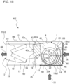
- Fig. 13 is a side view schematically illustrating an example of the internal configuration of an air-conditioning apparatus 40C according to Embodiment 4. Parts having the same configurations as those of the air-conditioning apparatus 40 and other apparatuses illustrated in Figs. 1 to 12 have the same reference signs, and their descriptions are omitted. The positions of the boundaries 60 and the fixing portions 20 of a centrifugal air-sending device 1C housed in the air-conditioning apparatus 40C according to Embodiment 4 are further specified. Thus, the configurations in which the boundaries 60 and the fixing portions 20 of the centrifugal air-sending device 1C are located will be mainly described below by use of Fig. 13 .
- the configurations of the air-conditioning apparatus 40C and the centrifugal air-sending device 1C according to Embodiment 4 are the same as the respective configurations of the air-conditioning apparatus 40 and the centrifugal air-sending device 1 according to Embodiment 1 unless otherwise described.
- the substantially triangular area defined by the first virtual lines CL and the line that represents the housing inlet 18 is defined as the area SB.
- the fixing portions 20 of the centrifugal air-sending device 1C are each located, when viewed in the axial direction of the rotation axis RS of the fan 2, in an area other than the area SB defined by the first virtual lines CL and the line that represents the housing inlet 18.
- a virtual line that connects the inner end portion 41a and the rotation axis RS is defined as a first reference line SL1
- the position that is located on the first reference line SL1 and that is located at the middle between the inner end portion 41a and the rotation axis RS is defined as a middle position M1.
- a virtual line that includes the middle position M1 and that extends in an up-down direction is defined as a second reference line SL2.
- the second reference line SL2 is, for example, a line in a weight direction.
- the fixing portions 20 are located in a portion of the side wall 4a located between the second reference line SL2 and the line that represents the housing inlet 18. Thus, as illustrated in Fig. 13 , the fixing portions 20 are each located in an area SC of the side wall 4a, the area SC being located between the area SB and the second reference line SL2.
- the air-conditioning apparatus 40C is the same, as the air-conditioning apparatus 40 in Embodiment 1, in the positions at which the boundaries 60 are located and the positions at which the fixing portions 20 are located and thus achieves effects similar to those of the air-conditioning apparatus 40.
- the fixing portions 20 are located in the portion of the side wall 4a located between the second reference line SL2 and the line that represents the housing inlet 18.
- the fixing portions 20 are located away from the housing inlet 18 of the air-conditioning apparatus 40C, and the air-conditioning apparatus 40C is thus capable of inhibiting interference between the fixing portions 20 and high-velocity air flowing in through the housing inlet 18.
- the air-conditioning apparatus 40C inhibits separation of air flowing in the bell mouths 3 and is thus capable of inhibiting a reduction in the amount of gas flowing into the scroll casing 4.
- the fixing portions 20 are located in the portion of the side wall 4a located between the second reference line SL2 and the line that represents the housing inlet 18, it is possible to balance the surface area of the first casing part 45 and the surface area of the second casing part 46 of the centrifugal air-sending device 1C with each other.
- Fig. 14 is a side view schematically illustrating an example of the internal configuration of an air-conditioning apparatus 40D according to Embodiment 5. Parts having the same configurations as those of the air-conditioning apparatus 40 and other apparatuses illustrated in Figs. 1 to 13 have the same reference signs, and their descriptions are omitted.
- the air-conditioning apparatus 40D according to Embodiment 5 differs from the air-conditioning apparatus 40 according to Embodiment 1 in the position at which the housing inlet 18 is located in a housing 16D.
- the relationship between the housing 16D and the centrifugal air-sending device 1 will be mainly described below by use of Fig. 14 .
- the configuration of the air-conditioning apparatus 40D according to Embodiment 5 is the same as the configuration of the air-conditioning apparatus 40 according to Embodiment 1 unless otherwise described.
- the housing 16D has an inlet wall 16b1 having the housing inlet 18 and the outlet wall 16c2 having the housing outlet 17.
- the inlet wall 16b1 forms a portion of a bottom wall of the housing 16D.
- the inlet wall 16b1 is a portion of the bottom portion 16b.
- the outlet wall 16c2 forms a side wall of the housing 16D.
- the second casing part 46 of the scroll casing 4 has a portion of the circumferential wall 4c facing the housing inlet 18.
- Other components are not located between the housing inlet 18 and the portion of the circumferential wall 4c facing the housing inlet 18.
- the portion of the circumferential wall 4c and the housing inlet 18 directly face each other.
- first virtual lines CL When viewed in the axial direction of the rotation axis RS, virtual lines that connect opposite ends 18d and 18e of the housing inlet 18 and the rotation axis RS are defined as first virtual lines CL.
- the end 18d When viewed in the axial direction of the rotation axis RS, the end 18d is an end closer to the housing outlet 17 or an end closer to the front of the housing 16D than is the end 18e, which is an end closer to the rear of the housing 16D than is the end 18d.
- the side of the housing 16D having the housing outlet 17 is the front of the housing 16D
- the side of the housing 16D opposite to the housing outlet 17 is the rear of the housing 16D.
- a substantially triangular area defined by the first virtual lines CL and a line that represents the housing inlet 18 is defined as an area SB.
- the fixing portions 20 of the centrifugal air-sending device 1 are each located, when viewed in the axial direction of the rotation axis RS of the fan 2, in an area other than the area SB defined by the first virtual lines CL and the line that represents the housing inlet 18.
- the air-conditioning apparatus 40D is the same, as the air-conditioning apparatus 40 in Embodiment 1, in the positions at which the boundaries 60 are located and the positions at which the fixing portions 20 are located and thus achieves effects similar to those of the air-conditioning apparatus 40.
- the air-conditioning apparatus 40D is capable of sucking air through the bottom and discharging conditioned air sideward.
- Fig. 15 is a side view schematically illustrating an example of the internal configuration of an air-conditioning apparatus 40E according to Embodiment 6. Parts having the same configurations as those of the air-conditioning apparatus 40 and other apparatuses illustrated in Figs. 1 to 14 have the same reference signs, and their descriptions are omitted.
- the air-conditioning apparatus 40E according to Embodiment 6 differs from the air-conditioning apparatus 40 according to Embodiment 1 in the position at which the housing inlet 18 is located in a housing 16E.
- the relationship between the housing 16E and the centrifugal air-sending device 1 will be mainly described below by use of Fig. 15 .
- the configuration of the air-conditioning apparatus 40E according to Embodiment 6 is the same as the configuration of the air-conditioning apparatus 40 according to Embodiment 1 unless otherwise described.
- the housing 16E has the inlet wall 16b1 having the housing inlet 18 and the outlet wall 16c2 having the housing outlet 17.
- the inlet wall 16b1 forms a portion of a bottom wall of the housing 16E.
- the inlet wall 16b1 is a portion of the bottom portion 16b.
- the outlet wall 16c2 forms a side wall of the housing 16E.
- the housing 16E has, as one of the side portions 16c, the inlet wall 16c1 having the housing inlet 18.
- the inlet wall 16c1 and the outlet wall 16c2 of the housing 16E form side wall surfaces located opposite to each other across the heat exchanger 10 and the centrifugal air-sending devices 1.
- the housing 16E has two air inlets, which are the housing inlet 18 formed in the inlet wall 16b1 and the housing inlet 18 formed in the inlet wall 16c1.
- the second casing part 46 of the scroll casing 4 has a portion of the circumferential wall 4c facing the two air inlets, which are the housing inlet 18 formed in the inlet wall 16b1 and the housing inlet 18 formed in the inlet wall 16c1.
- Other components are not located between the housing inlets 18 and the portion of the circumferential wall 4c facing the housing inlets 18.
- the portion of the circumferential wall 4c and the housing inlets 18 directly face each other.
- the shortest virtual line that connects a surface that represents the housing inlet 18 of the inlet wall 16c1 and the rotation axis RS is defined as a lateral line EL1.
- the lateral line EL1 is a line perpendicular to the surface that represents the housing inlet 18 of the inlet wall 16c1.
- the shortest virtual line that connects a surface that represents the housing inlet 18 of the inlet wall 16b1 and the rotation axis RS is defined as a longitudinal line EL2.
- the longitudinal line EL2 is a line perpendicular to the surface that represents the housing inlet 18 of the inlet wall 16b1.
- an area defined by a line that represents the housing inlet 18 of the inlet wall 16c1, the lateral line EL1, a line that represents the housing inlet 18 of the inlet wall 16b1, and the longitudinal line EL2 is defined as an area SE.
- the area SE does not include the fixing portions 20 and the boundaries 60.
- the area SE is an area that is close to two air inlets, which are the housing inlet 18 formed in the inlet wall 16b1 and the inlet wall 16c1, and into which the amount of sucked air is relatively large.
- the area SE does not include the fixing portions 20 and the boundaries 60.
- the fixing portions 20 are not located in such an area into which the amount of sucked air is relatively large.
- the air-conditioning apparatus 40E is capable of reducing the amount of airflow that interferes with the fixing portions 20.
- the air-conditioning apparatus 40E is capable of inhibiting a reduction in the amount of gas flowing into the scroll casing 4.
- the air-conditioning apparatus 40E is capable of inhibiting generation of noise caused by interference between the airflow and the fixing portions 20 and is thus capable of reducing noise emitted from the air-conditioning apparatus 40E compared with the air-conditioning apparatus 40L.
- the area SE does not include the fixing portions 20 and the boundaries 60.
- the velocity of airflow that interferes with the fixing portions 20 located away from the two air inlets, which are the housing inlet 18 formed in the inlet wall 16b1 and the inlet wall 16c1 is low.
- the air-conditioning apparatus 40E is capable of inhibiting a reduction in the amount of gas flowing into the scroll casing 4.
- the air-conditioning apparatus 40E is capable of inhibiting generation of noise caused by interference between the airflow and the fixing portions 20 and is thus capable of reducing noise emitted from the air-conditioning apparatus 40E compared with the air-conditioning apparatus 40L.
- Embodiments 1 to 6 described above an example is described in which the double suction centrifugal air-sending device 1 having the double suction fan 2, in which the blades 2d are located on both sides of a main plate 11.
- Embodiments 1 to 6 are also applicable to a single suction centrifugal air-sending device 1 having a single suction fan 2, in which the blades 2d are located on only one side of the main plate 11.
- Embodiments 1 to 6 described above may be combined with each other.
- the configurations in the embodiments above are examples.
- the configurations are allowed to be combined with other known techniques, and some of the configurations are allowed to be omitted or modified without departing from the gist.
- centrifugal air-sending device 1A: centrifugal air-sending device
- 1B centrifugal air-sending device
- 1C centrifugal air-sending device
- 1L centrifugal air-sending device
- 4B scroll casing
- 4L scroll casing
- 4c circumferential wall
- 6a output shaft
- 9a motor support
- 10: heat exchanger 11: main plate, 13: heat-insulating material
Landscapes
- Engineering & Computer Science (AREA)
- Chemical & Material Sciences (AREA)
- Combustion & Propulsion (AREA)
- Mechanical Engineering (AREA)
- General Engineering & Computer Science (AREA)
- Structures Of Non-Positive Displacement Pumps (AREA)
- Air-Conditioning Room Units, And Self-Contained Units In General (AREA)
- Air Filters, Heat-Exchange Apparatuses, And Housings Of Air-Conditioning Units (AREA)
Abstract
Description
- The present disclosure relates to an air-conditioning apparatus including a centrifugal air-sending device.
- Some existing air-conditioning apparatus includes, between an air inlet and an air outlet, a heat exchanger and a centrifugal air-sending device that has a scroll casing. Rotation of a fan housed in a scroll casing of such an air-conditioning apparatus causes air sucked through an inlet of the air-conditioning apparatus to flow into the fan along a bell mouth formed at a suction port of the scroll casing. The pressure of airflow discharged from the fan is increased in the scroll casing. Subsequently, the airflow is discharged from the scroll casing, then passes through a heat exchanger, and is discharged into an air-conditioning target space through an outlet of the air-conditioning apparatus.
- A scroll casing to be used in an air-conditioning apparatus is sometimes separated into two parts to contain a fan. In view of ease of production, the scroll casing separated into the two parts has a boundary that is located in a component forming a discharge port of the scroll casing and at which the two parts are fixed to each other and another boundary located opposite to the boundary across a suction port of the scroll casing (see, for example, Patent Literature 1). To fix the two separated parts to each other, the air-conditioning apparatus in
Patent Literature 1 further has a fixing portion located at a position in a wall surface of the scroll casing in the vicinity of each boundary. - Patent Literature 1:
Japanese Unexamined Patent Application Publication No. 2005-69177 - However, the velocity of air flowing into the suction port of the scroll casing increases at an inlet of the air-conditioning apparatus. Thus, interference between airflow and the fixing portion located at the inlet of the air-conditioning apparatus in
Patent Literature 1 may cause separation of air flowing in a bell mouth and thus may reduce the amount of gas flowing into the scroll casing. - The present disclosure is made to solve such a problem, and an object of the present disclosure is to obtain an air-conditioning apparatus that inhibits a reduction in the amount of gas flowing into a scroll casing of a centrifugal air-sending device. Solution to Problem
- An air-conditioning apparatus according to an embodiment of the present disclosure includes a centrifugal air-sending device that has a fan driven to rotate and a scroll casing that houses the fan, the scroll casing having a circumferential wall and a side wall, the circumferential wall being formed in a volute shape, the side wall having a suction port of air; a driving power supply configured to supply driving power to the fan; a heat exchanger located to face a discharge port of air, the discharge port being formed in the scroll casing; and a housing that houses the centrifugal air-sending device, the driving power supply, and the heat exchanger, the housing having a partition plate that partitions an interior of the housing into an air-sending chamber in which the fan is located and a heat-exchanging chamber in which the heat exchanger is located, the housing having a housing inlet through which air that flows into the air-sending chamber passes and a housing outlet through which air that flows out of the heat-exchanging chamber passes. The scroll casing has a first casing part that has a discharge part that forms the discharge port, the discharge part being fixed to the partition plate, a second casing part that has a portion of the circumferential wall that faces the housing inlet, the second casing part being fixed to the first casing part in such a manner that the second casing part is capable of being detached, and a fixing portion located in the side wall and at which the first casing part and the second casing part are fixed to each other. The first casing part and the second casing part are fixed to each other at a boundary. The boundary extends over the side wall and the circumferential wall. The boundary is located in a portion other than the discharge part. The fixing portion is located, when the fixing portion is viewed in an axial direction of a rotation axis of the fan, in an area other than an area defined by first virtual lines and a line that represents the housing inlet, the first virtual lines being virtual lines that connect opposite ends of the housing inlet and the rotation axis.
- According to an embodiment of the present disclosure, the centrifugal air-sending device has the fixing portion at which the first casing part and the second casing part are fixed to each other. The fixing portion is located in the side wall. The fixing portion is located, when the fixing portion is viewed in the axial direction of the rotation axis of the fan, in an area other than the area defined by the first virtual lines and the line that represents the housing inlet, the first virtual lines being the virtual lines that connect the opposite ends of the housing inlet and the rotation axis. The fixing portion is located away from the housing inlet of the air-conditioning apparatus, and the air-conditioning apparatus is thus capable of inhibiting interference between the fixing portion and high-velocity air flowing in through the housing inlet. As a result, the air-conditioning apparatus inhibits separation of air flowing in a bell mouth and is thus capable of inhibiting a reduction in the amount of gas flowing into the scroll casing. Brief Description of Drawings
-
- [
Fig. 1] Fig. 1 is a perspective view of a centrifugal air-sending device according toEmbodiment 1. - [
Fig. 2] Fig. 2 is a schematic diagram of the interior of the centrifugal air-sending device according toEmbodiment 1 when the centrifugal air-sending device is viewed in the axial direction of a rotation axis. - [
Fig. 3] Fig. 3 is a schematic diagram of the exterior of the centrifugal air-sending device according toEmbodiment 1 when the centrifugal air-sending device is viewed in the axial direction of the rotation axis. - [
Fig. 4] Fig. 4 is a perspective view schematically illustrating an example of an air-conditioning apparatus according toEmbodiment 1. - [
Fig. 5] Fig. 5 is a schematic diagram illustrating an example of the internal configuration of the air-conditioning apparatus according toEmbodiment 1. - [
Fig. 6] Fig. 6 is a side view schematically illustrating an example of the internal configuration of the air-conditioning apparatus according toEmbodiment 1. - [
Fig. 7] Fig. 7 is a side view schematically illustrating the internal configuration of a modification example of the air-conditioning apparatus according toEmbodiment 1. - [
Fig. 8] Fig. 8 is a schematic diagram of a centrifugal air-sending device according to a comparative example when the centrifugal air-sending device is viewed in the axial direction of a rotation axis. - [
Fig. 9] Fig. 9 is a schematic diagram of the separated centrifugal air-sending device according to the comparative example. - [
Fig. 10] Fig. 10 is a schematic diagram illustrating an example of the internal configuration of an air-conditioning apparatus according to the comparative example. - [
Fig. 11] Fig. 11 is a side view schematically illustrating an example of the internal configuration of an air-conditioning apparatus according toEmbodiment 2. - [
Fig. 12] Fig. 12 is a side view schematically illustrating an example of the internal configuration of an air-conditioning apparatus according toEmbodiment 3. - [
Fig. 13] Fig. 13 is a side view schematically illustrating an example of the internal configuration of an air-conditioning apparatus according toEmbodiment 4. - [
Fig. 14] Fig. 14 is a side view schematically illustrating an example of the internal configuration of an air-conditioning apparatus according toEmbodiment 5. - [
Fig. 15] Fig. 15 is a side view schematically illustrating an example of the internal configuration of an air-conditioning apparatus according toEmbodiment 6. - An air-
conditioning apparatus 40 according to an embodiment of the present disclosure will be described below with reference to the drawings, for example. For example, the relative size relationships or the shapes of the components in the following drawings includingFig. 1 may differ from those of actual ones. In the following drawings, components having the same reference signs are the same or corresponding components, and this applies to the entire description. Terms that mean directions (for example, "up", "down", "right", "left", "forward", and "backward") are used as appropriate to make the description easy to understand. However, these terms are merely used for convenience of description and do not limit the locations and the orientations of apparatuses or components. -
Fig. 1 is a perspective view of a centrifugal air-sendingdevice 1 according toEmbodiment 1.Fig. 2 is a schematic diagram of the interior of the centrifugal air-sending device 1 according toEmbodiment 1 when the centrifugal air-sending device 1 is viewed in the axial direction of a rotation axis RS.Fig. 3 is a schematic diagram of the exterior of the centrifugal air-sending device 1 according toEmbodiment 1 when the centrifugal air-sending device 1 is viewed in the axial direction of the rotation axis RS.Fig. 2 does not illustrate abell mouth 3 to illustrate the internal structure of the centrifugal air-sending device 1. - The centrifugal air-
sending device 1 is a double suction centrifugal air-sending device 1, into which air is sucked from both sides of the centrifugal air-sending device 1 in the axial direction of the rotation axis RS of afan 2. The configuration of the part of the centrifugal air-sending device 1 on one surface of amain plate 2a is similar to the configuration of the part of the centrifugal air-sending device 1 on the other surface of themain plate 2a. Thus, the configuration of the centrifugal air-sending device 1 is described by use ofFig. 1 , and the configuration of the part opposite to the part of the centrifugal air-sending device 1 illustrated inFig. 1 is not illustrated. - First, the basic structure of the centrifugal air-
sending device 1 will be described by use ofFigs. 1 to 3 . The centrifugal air-sending device 1 is, for example, a multiblade centrifugal air-sending device 1, such as a sirocco fan and a turbo fan. The centrifugal air-sending device 1 has thefan 2, which is configured to generate airflow, and ascroll casing 4, which houses thefan 2. - The
fan 2 is driven to rotate by, for example, a motor (not illustrated) and forcibly sends air outward in radial directions with the centrifugal force generated by the rotation. As illustrated inFigs. 1 and2 , thefan 2 has themain plate 2a, which has a disk shape, and a plurality ofblades 2d, which are installed on a peripheral portion 2a1 of themain plate 2a. Themain plate 2a may have any shape, such as a polygonal shape, other than a disk shape as long as themain plate 2a has a plate-like shape. Anaxial portion 2b, to which the motor (not illustrated) is connected, is located at the center of themain plate 2a. Themain plate 2a is driven to rotate by the motor via theaxial portion 2b. - The
blades 2d are located on the circumference around theaxial portion 2b. The base ends of theblades 2d are fixed to themain plate 2a. Theblades 2d are located on both sides of themain plate 2a in the axial direction of the rotation axis RS of thefan 2. Theblades 2d are located on the peripheral portion 2a1 of themain plate 2a with certain spaces between theblades 2d. Theblades 2d each have, for example, a curved rectangular plate-like shape and are each installed to extend in a radial direction or to be inclined at a predetermined angle to a radial direction. - The
blades 2d are each formed into a two-dimensional blade in which the same sectional shape is continuous in the axial direction of the rotation axis RS but may be each formed into a three-dimensional blade having a twisted shape. Theblades 2d are located to stand substantially perpendicularly to themain plate 2a, but the configuration of theblades 2d is not limited to this description. Theblades 2d may be located to be inclined to a direction perpendicular to themain plate 2a. - The
fan 2 has side plates (not illustrated) that each have an annular shape and that are each located at the corresponding ends of theblades 2d in the axial direction of the rotation axis RS. The end of each of theblades 2d to which the side plate is attached is one end opposite to the other end of theblade 2d connected to themain plate 2a. The side plate maintains the positional relationship between the tips of theblades 2d and reinforces theblades 2d by being connected to theblades 2d. - As illustrated in
Fig. 1 , thefan 2 has a cylindrical shape formed by theblades 2d located on themain plate 2a. At respective ends of theblades 2d opposite to themain plate 2a in the axial direction of the rotation axis RS, thefan 2 hassuction ports 2e for allowing gas to flow through into the spaces defined by themain plate 2a and theblades 2d. In thefan 2, theblades 2d are located at each side of themain plate 2a, and thesuction ports 2e are formed at each side of themain plate 2a. - The
fan 2 is driven to rotate around the rotation axis RS by driving the motor (not illustrated). By rotating thefan 2, gas outside the centrifugal air-sendingdevice 1 flows alongbell mouths 3 and is sucked into the spaces defined by themain plate 2a and theblades 2d throughsuction ports 5, which are each formed in thescroll casing 4, and thesuction ports 2e of thefan 2. By rotating thefan 2, the air sucked into the spaces defined by themain plate 2a and theblades 2d is then sent outward in a radial direction through a space between eachblade 2d and the correspondingadjacent blade 2d. - As illustrated in
Fig. 1 , thescroll casing 4 houses thefan 2 in its inside. Thescroll casing 4 rectifies the flow of air blown out of thefan 2. Thescroll casing 4 is made of a resin, but the material for thescroll casing 4 is not limited to such a resin. Thescroll casing 4 has ascroll part 41 and adischarge part 42. - The
scroll part 41 defines an air passage in which the dynamic pressure of airflow generated by thefan 2 is converted into a static pressure. Thescroll part 41 hasside walls 4a, which surround thefan 2 in the axial direction of the rotation axis RS of theaxial portion 2b included in thefan 2, and acircumferential wall 4c, which surrounds thefan 2 in radial directions from the rotation axis RS. Theside walls 4a have therespective suction ports 5 through which air is let in. - In addition, the
scroll part 41 has atongue portion 43, which has a curved surface between thedischarge part 42 and aninner end portion 41a of thecircumferential wall 4c and which is a restriction portion required for blowing out, in a centrifugal direction, the air that has flowed in through thesuction ports 5 and increasing the air pressure. A radial direction from the rotation axis RS means a direction perpendicular to the rotation axis RS. The internal space of thescroll part 41 defined by thecircumferential wall 4c and theside walls 4a is a space in which the air that has blown out of thefan 2 flows along thecircumferential wall 4c. - The
side wall 4a is located at each side of thefan 2 in the axial direction of the rotation axis RS of thefan 2. As illustrated inFigs. 1 and3 , theside walls 4a of thescroll casing 4 have therespective suction ports 5 for letting air in in such a manner that air is allowed to flow between thefan 2 and the outside of thescroll casing 4. - The
suction ports 5 each have a circular shape. Thefan 2 is located in such a manner that the center of each of thesuction ports 5 substantially coincides with the center of theaxial portion 2b of thefan 2. The shape of thesuction port 5 is not limited to a circular shape and may be a different shape such as an oval shape. - The
scroll casing 4 of the centrifugal air-sendingdevice 1 is a double suction casing having theside wall 4a having thesuction port 5 at each side of themain plate 2a in the axial direction of the rotation axis RS of thefan 2. In the centrifugal air-sendingdevice 1, thescroll casing 4 has twoside walls 4a, and the twoside walls 4a are located to face each other. - As illustrated in
Fig. 1 , thescroll casing 4 has, as theside walls 4a, a first side wall 4a1 and a second side wall 4a2. The first side wall 4a1 extends along a first end 4c11, which is one end of thecircumferential wall 4c in the axial direction of the rotation axis RS. The second side wall 4a2 extends along a second end 4c12, which is the other end of thecircumferential wall 4c in the axial direction of the rotation axis RS. The first side wall 4a1 has thesuction port 5 facing one surface of themain plate 2a. The second side wall 4a2 has thesuction port 5 facing the other surface of themain plate 2a. - As illustrated in
Figs. 1 and3 , thesuction ports 5 of air located in therespective side walls 4a are each formed by thebell mouth 3. Thebell mouths 3 rectify the flow of gas to be sucked into thefan 2 and allow the gas to flow through into thesuction ports 2e of thefan 2. Thebell mouths 3 are each formed in such a manner that the opening diameter is gradually reduced from the outside toward the inside of thescroll casing 4. With theside walls 4a having this configuration, air in the vicinity of thesuction ports 5 flows smoothly along thebell mouths 3 and efficiently into thefan 2 through thesuction ports 5. - The
circumferential wall 4c is a wall located between theside walls 4a facing each other and has a curved surface in a rotation direction R of thefan 2. Thecircumferential wall 4c guides, along the curved wall surface, airflow generated by thefan 2 to adischarge port 42a via thescroll part 41. For example, thecircumferential wall 4c is located parallel to the axial direction of the rotation axis RS of thefan 2 to surround thefan 2. Thecircumferential wall 4c may be inclined to the axial direction of the rotation axis RS of thefan 2 and is not limited to thecircumferential wall 4c located parallel to the axial direction of the rotation axis RS. Thecircumferential wall 4c surrounds thefan 2 in radial directions from the rotation axis RS and has an inner circumferential surface facing theblades 2d. Thecircumferential wall 4c faces the air discharge sides of theblades 2d of thefan 2. - As illustrated in
Figs. 2 and3 , thecircumferential wall 4c is located to extend from theinner end portion 41a located at the boundary between thecircumferential wall 4c and thetongue portion 43 to anouter end portion 41b located at the boundary between thescroll part 41 and thedischarge part 42 away from thetongue portion 43 in the rotation direction R of thefan 2. Theinner end portion 41a is an end portion of thecircumferential wall 4c having the curved surface, the end portion being upstream for airflow generated by rotation of thefan 2. Theouter end portion 41b is an end portion of thecircumferential wall 4c having the curved surface, the end portion being downstream for airflow generated by rotation of thefan 2. - The
circumferential wall 4c has a volute shape in the rotation direction R. Examples of such a volute shape include volute shapes by use of a logarithmic spiral, an Archimedean spiral, and an involute curve. The inner circumferential surface of thecircumferential wall 4c is a surface smoothly curved in the circumferential direction of thefan 2 from theinner end portion 41a, which is an inner end of the volute shape, to theouter end portion 41b, which is an outer end of the volute shape. With such a configuration, the air sent out of thefan 2 flows smoothly in the internal space between thefan 2 and thecircumferential wall 4c in a direction toward thedischarge part 42. Thus, in thescroll casing 4, the static pressure of air increases efficiently from thetongue portion 43 toward thedischarge part 42. - The
discharge part 42 forms thedischarge port 42a, through which the airflow that has been generated by thefan 2 and that has passed through thescroll part 41 is discharged. Thedischarge part 42 is made of a hollow pipe whose section orthogonal to a direction in which air flows along thecircumferential wall 4c has a rectangular shape. The sectional shape of thedischarge part 42 is not limited to a rectangular shape. Thedischarge part 42 defines a passage for guiding, to be discharged to the outside of thescroll casing 4, the air that flows between thecircumferential wall 4c and thefan 2 after being sent out of thefan 2. - As illustrated in
Fig. 1 , thedischarge part 42 has an extendedplate 42b, adiffuser plate 42c, a portion of the first side wall 4a1, and a portion of the second side wall 4a2. Theextended plate 42b is a plate-like portion integrally formed with thecircumferential wall 4c and that extends from theouter end portion 41b of thecircumferential wall 4c. Thediffuser plate 42c is a plate-like portion that is integrally formed with thetongue portion 43 of thescroll casing 4 and that is located to face theextended plate 42b. Thediffuser plate 42c is formed to have a predetermined angle with theextended plate 42b in such a manner that the sectional area of the passage increases gradually in the direction in which air flows in thedischarge part 42. - The
extended plate 42b and thediffuser plate 42c are each formed between the first side wall 4a1 and the second side wall 4a2. In such a manner, thedischarge part 42 has the passage whose section has a rectangular shape and that is defined by theextended plate 42b, thediffuser plate 42c, the first side wall 4a1, and the second side wall 4a2. - The
scroll casing 4 has thetongue portion 43 between thediffuser plate 42c of thedischarge part 42 and theinner end portion 41a of thecircumferential wall 4c. Thetongue portion 43 is formed with a predetermined curvature radius. Thecircumferential wall 4c is smoothly continuous with thediffuser plate 42c via thetongue portion 43. - The
tongue portion 43 inhibits air from flowing from the outer end into the inner end of the volute-shaped passage formed in thescroll casing 4. Thetongue portion 43 is located in an upstream section of the air passage and has a function of separating air flowing in the rotation direction R of thefan 2 and air flowing in the discharge direction from a downstream section of the air passage toward thedischarge port 42a. In addition, the static pressure of air flowing into thedischarge part 42 increases during the air passing through thescroll casing 4 and becomes higher than the pressure in thescroll casing 4. Thus, thetongue portion 43 has a function of separating areas different from each other in pressure as described above. - As illustrated in
Figs. 1 and3 , thescroll casing 4 has afirst casing part 45, asecond casing part 46, and fixingportions 20. Thescroll casing 4 is allowed to be separated into thefirst casing part 45 and thesecond casing part 46. That is, thescroll casing 4 is formed by combining thefirst casing part 45 and thesecond casing part 46. - The
first casing part 45 has a portion of thescroll part 41 and thedischarge part 42, which forms thedischarge port 42a. Thefirst casing part 45 has a portion of thecircumferential wall 4c and a portion of each of theside walls 4a. In addition, thefirst casing part 45 has a portion of each of thebell mouths 3. - The
second casing part 46 is formed by a portion of thescroll part 41. Thesecond casing part 46 has a portion of thecircumferential wall 4c and a portion of each of theside walls 4a. In addition, thesecond casing part 46 has a portion of each of thebell mouths 3. Thesecond casing part 46 is fixed to thefirst casing part 45 in such a manner that thesecond casing part 46 is capable of being detached. Thefan 2 is exposed by detaching thesecond casing part 46 from thefirst casing part 45. - The
bell mouths 3, each of which has an annular shape when viewed parallelly to the axial direction of the rotation axis RS, are each formed by combining thefirst casing part 45 and thesecond casing part 46. That is, when viewed parallelly to the axial direction of the rotation axis RS, thesuction ports 5 of thescroll casing 4 are each formed by combining thefirst casing part 45 and thesecond casing part 46. - The
scroll casing 4 contains thefan 2 and thus hasboundaries 60 for convenience of assembly. Theboundaries 60, at which thefirst casing part 45 and thesecond casing part 46 are fixed to each other, extend over theside walls 4a and thecircumferential wall 4c of thescroll casing 4. In addition, theboundaries 60 are each located in a portion other than thedischarge part 42. More specifically, theboundaries 60 are each located in an area other than an area SA located between theinner end portion 41a, which is an inner end of thescroll casing 4, and thedischarge port 42a in the direction in which air flows in thedischarge part 42. - As illustrated in
Fig. 3 , the area SA is, for example, an area between anedge 42d and aboundary line 42e when viewed in a direction parallel to the axial direction of the rotation axis RS of thefan 2. Theedge 42d is an end edge of each of theside walls 4a, and the end edges are each included in thedischarge port 42a. When viewed in the direction parallel to the axial direction of the rotation axis RS of thefan 2, theboundary line 42e is a virtual line that includes theinner end portion 41a and that is parallel to theedge 42d. The parallel relationship between theboundary line 42e and theedge 42d includes a completely parallel relationship between theboundary line 42e and theedge 42d and a substantially parallel relationship between theboundary line 42e and theedge 42d. - As illustrated in
Figs. 2 and3 , theboundaries 60 include afirst boundary 61, which is located upstream for airflow in a direction in which air flows in thecircumferential wall 4c, the direction being represented by airflow AR illustrated inFig. 2 , and asecond boundary 62, which is located downstream for airflow in the direction in which air flows in thecircumferential wall 4c. Thefirst casing part 45 and thesecond casing part 46 of thescroll casing 4 are fixed to each other at the twoboundaries 60, which are thefirst boundary 61 and thesecond boundary 62. In other words, thescroll casing 4 is separated into the two components, which are thefirst casing part 45 and thesecond casing part 46, at the twoboundaries 60, which are thefirst boundary 61 and thesecond boundary 62. - The fixing
portions 20 are located at theboundaries 60 of thescroll casing 4. The fixingportions 20 are used to fix thefirst casing part 45 and thesecond casing part 46 to each other. The fixingportions 20 are located in theside wall 4a of thescroll casing 4. - As illustrated in
Fig. 3 , the fixingportions 20 include first fixingportions 20A and second fixingportions 20B. Thefirst fixing portions 20A are each located at thefirst boundary 61. Thesecond fixing portions 20B are each located at thesecond boundary 62. That is, thefirst fixing portion 20A is located upstream, for airflow, of thesecond fixing portion 20B in the direction in which air flows in thecircumferential wall 4c, the direction being represented by the airflow AR illustrated inFig. 2 , and thesecond fixing portion 20B is located downstream, for airflow, of thefirst fixing portion 20A in the direction in which air flows in thecircumferential wall 4c. - For example, the fixing
portion 20 is formed by fitting and joining afirst engagement portion 21, which is located in thefirst casing part 45, and asecond engagement portion 22, which is located in thesecond casing part 46, to each other. Alternatively, the fixingportion 20 may be formed by screwing together thefirst engagement portion 21, which is located in thefirst casing part 45, and thesecond engagement portion 22, which is located in thesecond casing part 46. The configuration of the fixingportion 20 is not limited to these configurations. -
Fig. 4 is a perspective view schematically illustrating an example of the air-conditioning apparatus 40 according toEmbodiment 1.Fig. 5 is a schematic diagram illustrating an example of the internal configuration of the air-conditioning apparatus 40 according toEmbodiment 1.Fig. 6 is a side view schematically illustrating an example of the internal configuration of the air-conditioning apparatus 40 according toEmbodiment 1.Fig. 5 does not illustrate top components such as atop portion 16a to illustrate the internal configuration of the air-conditioning apparatus 40. The air-conditioning apparatus 40 including the centrifugal air-sendingdevices 1 will be described by use ofFigs. 4 to 6 . - The air-
conditioning apparatus 40 is an apparatus that is configured to condition air in an air-conditioning target space and that is configured to control the temperature and the humidity of sucked air to discharge the air into an air-conditioning target space. The air-conditioning apparatus 40 is a ceiling suspended apparatus, which is suspended from a ceiling, but is not limited to such a ceiling suspended apparatus. - The air-
conditioning apparatus 40 includes the centrifugal air-sendingdevices 1, a drivingpower supply 6, which is configured to supply driving power to thefan 2 of each of the centrifugal air-sendingdevices 1, and aheat exchanger 10, which is located to face thedischarge ports 42a of air, thedischarge port 42a being formed in each of thescroll casings 4 of the centrifugal air-sendingdevices 1. In addition, the air-conditioning apparatus 40 includes ahousing 16, which houses, in its inside, the centrifugal air-sendingdevices 1, the drivingpower supply 6, and theheat exchanger 10 and which is installed on a ceiling of an air-conditioning target space. Furthermore, the air-conditioning apparatus 40 may include a heat-insulatingmaterial 13 in a heat-exchangingchamber 26, which will be described later. - As illustrated in
Fig. 4 , thehousing 16 has a box shape and has thetop portion 16a, abottom portion 16b, andside portions 16c to form a cuboid shape. The shape of thehousing 16 is not limited to a cuboid shape and may be a different shape such as a cylindrical shape, a rectangular column shape, a circular cone shape, a shape having a plurality of corners, and a shape having a plurality of curved surfaces. - The
housing 16 has, as one of theside portions 16c, an inlet wall 16c1 having ahousing inlet 18. A filter for removing dust in air may be located at thehousing inlet 18. In addition, thehousing 16 has, as one of theside portions 16c, an outlet wall 16c2 having ahousing outlet 17. - The inlet wall 16c1 and the outlet wall 16c2 of the
housing 16 form side wall surfaces located opposite to each other across theheat exchanger 10 and the centrifugal air-sendingdevices 1. Thehousing inlet 18 is only required to be located at a position perpendicular to the axial direction of the rotation axis RS of each of the centrifugal air-sendingdevices 1. Thus, for example, thebottom portion 16b may have thehousing inlet 18. - Air that flows into an air-sending
chamber 25, which will be described later, passes through thehousing inlet 18 of thehousing 16. An arrow IR illustrated inFig. 6 represents air to be sucked into thehousing inlet 18. Air that flows out of the heat-exchangingchamber 26, which will be described later, passes through thehousing outlet 17 of thehousing 16. An arrow OR illustrated inFig. 6 represents air to be blown out of thehousing outlet 17. - As illustrated in
Figs. 4 and5 , thehousing outlet 17 and thehousing inlet 18 each have a rectangular shape. Each shape of thehousing outlet 17 and thehousing inlet 18 is not limited to a rectangular shape and may be a different shape such as a circular shape and an oval shape. - A
partition plate 19 partitions the internal space of thehousing 16 into the air-sendingchamber 25, which is a space located at the suction sides of thescroll casings 4, and the heat-exchangingchamber 26, which is a space located at the discharge sides of thescroll casings 4. That is, thepartition plate 19 partitions the internal space of thehousing 16 into the air-sendingchamber 25, in which thefans 2 are located, and the heat-exchangingchamber 26, in which theheat exchanger 10 is located. As illustrated inFig. 5 , thehousing 16 houses, in its inside, the drivingpower supply 6, the two centrifugal air-sendingdevices 1, and theheat exchanger 10. - The driving
power supply 6 is, for example, a motor. The drivingpower supply 6 is supported by amotor support 9a, which is fixed to thetop portion 16a of thehousing 16. The drivingpower supply 6 has anoutput shaft 6a. Theoutput shaft 6a is located to extend parallel to the inlet wall 16c1 having thehousing inlet 18 and the outlet wall 16c2 having thehousing outlet 17. - The centrifugal air-sending
devices 1 each have thefan 2 and thescroll casing 4 having thebell mouths 3. As illustrated inFigs. 5 and6 , thedischarge part 42 of thescroll casing 4 of the centrifugal air-sendingdevice 1 is fixed to thepartition plate 19. - As illustrated in
Fig. 5 , thefan 2 of each of the two centrifugal air-sendingdevices 1 of the air-conditioning apparatus 40 is attached to theoutput shaft 6a. The centrifugal air-sendingdevice 1 having thefan 2 forms airflow to be sucked into thehousing 16 from thehousing inlet 18 and blown out into an air-conditioning target space from thehousing outlet 17. The number of the centrifugal air-sendingdevices 1 to be located in thehousing 16 is not limited to two and may be one or three or more. - As illustrated in
Fig. 6 , thesecond casing part 46 of thescroll casing 4 has a portion of thecircumferential wall 4c facing thehousing inlet 18. Other components are not located between thehousing inlet 18 and the portion of thecircumferential wall 4c facing thehousing inlet 18. Thus, the portion of thecircumferential wall 4c and thehousing inlet 18 directly face each other. - Here, as illustrated in
Fig. 6 , when viewed in the axial direction of the rotation axis RS of thefan 2, virtual lines that connectopposite ends housing inlet 18 and the rotation axis RS are defined as first virtual lines CL. When viewed in the axial direction of the rotation axis RS, theend 18a is a top end of thehousing inlet 18, and theend 18b is a bottom end of thehousing inlet 18. - Then, as illustrated in
Fig. 6 , when viewed in the axial direction of the rotation axis RS of thefan 2, a substantially triangular area defined by the first virtual lines CL and a line that represents thehousing inlet 18 is defined as an area SB. As illustrated inFig. 6 , the fixingportions 20 of the centrifugal air-sendingdevice 1 are each located, when viewed in the axial direction of the rotation axis RS of thefan 2, in an area other than the area SB defined by the first virtual lines CL and the line that represents thehousing inlet 18. - The
first fixing portion 20A is located opposite to thesecond fixing portion 20B across the rotation axis RS. Thesecond fixing portion 20B is located opposite to thefirst fixing portion 20A across the rotation axis RS. The positional relationship between thefirst fixing portion 20A and thesecond fixing portion 20B is not limited to this relationship. - Similarly, the
first boundary 61 is located opposite to thesecond boundary 62 across the rotation axis RS. Thesecond boundary 62 is located opposite to thefirst boundary 61 across the rotation axis RS. The positional relationship between thefirst boundary 61 and thesecond boundary 62 is not limited to this relationship. - As described above, the
heat exchanger 10 is located to face thedischarge port 42a of the centrifugal air-sendingdevice 1. Theheat exchanger 10 is located in an air passage in thehousing 16 for air discharged by the centrifugal air-sendingdevice 1. Theheat exchanger 10 adjusts the temperature of air sucked into thehousing 16 through thehousing inlet 18 and to be blown out into an air-conditioning target space through thehousing outlet 17. A heat exchanger having a known structure is applicable to theheat exchanger 10. - The air-
conditioning apparatus 40 is configured in such a manner that thehousing inlet 18, thescroll casings 4 of the centrifugal air-sendingdevices 1, theheat exchanger 10, and thehousing outlet 17 are arranged in the named order in a direction from thehousing inlet 18 toward thehousing outlet 17 of the air-conditioning apparatus 40. In the case of such a ceiling suspended air-conditioning apparatus 40, these components are arranged in a horizontal direction. -
Fig. 7 is a side view schematically illustrating the internal configuration of a modification example of the air-conditioning apparatus 40 according toEmbodiment 1. As described above, for example, as illustrated inFig. 3 , the area SA is described as an area between theedge 42d and theboundary line 42e when viewed in the direction parallel to the axial direction of the rotation axis RS of thefan 2. However, the area SA is not limited to this area. For example, as illustrated inFig. 7 , a vertical virtual line that passes through theinner end portion 41a of thescroll casing 4 and that connects thetop portion 16a, which forms the top surface of thehousing 16, and thebottom portion 16b, which forms the bottom surface of thehousing 16, is defined as a virtual line FL. - In this case, the area SA may be an area of the
scroll casing 4 defined by the virtual line FL and a line that represents thedischarge port 42a. - When the
fans 2 are rotated by driving the drivingpower supply 6, air in an air-conditioning target space is sucked into thehousing 16 through thehousing inlet 18. The air sucked into thehousing 16 flows along thebell mouths 3 and is sucked into thefans 2. The air sucked into thefans 2 is blown out in radial directions of thefans 2. - The pressure of the air blown out of the
fans 2 increases while the air passes through thescroll casings 4. The air whose pressure is increased is blown out through thedischarge ports 42a of thescroll casings 4 and is then supplied to theheat exchanger 10. The air supplied to theheat exchanger 10 is subjected to heat exchange with a heat exchange medium such as refrigerant flowing in theheat exchanger 10 while the air passes through theheat exchanger 10, and the temperature and the humidity of the air are adjusted. The air that has passed through theheat exchanger 10 is blown out into the air-conditioning target space through thehousing outlet 17. - The centrifugal air-sending
device 1 has the fixingportions 20, at which thefirst casing part 45 and thesecond casing part 46 are fixed to each other. The fixingportions 20 are located in theside wall 4a. The fixingportions 20 are each located, when viewed in the axial direction of the rotation axis RS of thefan 2, in an area other than the area SB defined by the first virtual lines CL and the line that represents thehousing inlet 18, the first virtual lines CL being the virtual lines that connect the opposite ends of thehousing inlet 18 and the rotation axis RS. The fixingportions 20 are located away from thehousing inlet 18 of the air-conditioning apparatus 40, and the air-conditioning apparatus 40 is thus capable of inhibiting interference between the fixingportions 20 and high-velocity air flowing in through thehousing inlet 18. As a result, the air-conditioning apparatus 40 inhibits separation of air flowing in thebell mouths 3 and is thus capable of inhibiting a reduction in the amount of gas flowing into thescroll casing 4. -
Fig. 8 is a schematic diagram of a centrifugal air-sendingdevice 1L according to a comparative example when the centrifugal air-sendingdevice 1L is viewed in the axial direction of the rotation axis RS.Fig. 9 is a schematic diagram of the separated centrifugal air-sendingdevice 1L according to the comparative example.Fig. 10 is a schematic diagram illustrating an example of the internal configuration of an air-conditioning apparatus 40L according to the comparative example. The centrifugal air-sendingdevice 1L and the air-conditioning apparatus 40L according to the comparative example will be described by use ofFigs. 8 to 10 . - As illustrated in
Fig. 10 , the air-conditioning apparatus 40L according to the comparative example includes the centrifugal air-sendingdevices 1L. As illustrated inFigs. 8 and9 , ascroll casing 4L of each of the centrifugal air-sendingdevices 1L is separated into two parts, which are alower casing part 47L and anupper casing part 48L, to contain thefan 2. Thescroll casing 4L separated into the two parts, which are thelower casing part 47L and theupper casing part 48L, has aboundary 60L, which is located in adischarge part 42L forming thedischarge port 42a of thescroll casing 4L and at which the two parts are fixed to each other. In addition, thescroll casing 4L has anotherboundary 60L, which is located opposite to aboundary 60 of thedischarge part 42L across thesuction port 5 of thescroll casing 4L. - To fix the two separated parts, which are the
lower casing part 47L and theupper casing part 48L, to each other, the centrifugal air-sendingdevice 1L according to the comparative example has a fixingportion 20L located at a position in a side wall surface of thescroll casing 4L in the vicinity of eachboundary 60L. - Typically, when air that has flowed in through an inlet of an air-conditioning apparatus flows into a fan along a bell mouth of a scroll casing, the airflow varies in velocity with positions in the circumferential direction of the rotation axis of the fan, and the air velocity increases at the inlet of the air-conditioning apparatus. Thus, as illustrated in the area defined by a broken line BD illustrated in
Fig. 10 , in the air-conditioning apparatus 40L according to the comparative example, airflow AR and the fixingportion 20L located and facing thehousing inlet 18 of the air-conditioning apparatus 40L may interfere with each other. Such interference between the airflow AR and the fixingportion 20L located and facing thehousing inlet 18 of the air-conditioning apparatus 40L may cause separation of air flowing in a bell mouth and thus may reduce the amount of gas flowing into thescroll casing 4L. - On the other hand, the air-
conditioning apparatus 40 according toEmbodiment 1 has the configuration described above in which the fixingportions 20 are located away from thehousing inlet 18 of the air-conditioning apparatus 40 and is thus capable of inhibiting interference between the fixingportions 20 and high-velocity air flowing in through thehousing inlet 18. As a result, the air-conditioning apparatus 40 inhibits separation of air flowing in thebell mouths 3 and is thus capable of inhibiting a reduction in the amount of gas flowing into thescroll casings 4. - In addition, interference between the airflow AR and the fixing
portion 20L located and facing thehousing inlet 18 of the air-conditioning apparatus 40L according to the comparative example may cause noise and thus may increase noise emitted from the air-conditioning apparatus 40L. - On the other hand, the air-
conditioning apparatus 40 according toEmbodiment 1 has the configuration described above in which the fixingportions 20 are located away from thehousing inlet 18 of the air-conditioning apparatus 40 and is thus capable of inhibiting interference between the fixingportions 20 and high-velocity air flowing in through thehousing inlet 18. As a result, the air-conditioning apparatus 40 is capable of inhibiting generation of noise caused by interference between the fixingportions 20 and high-velocity air flowing in through thehousing inlet 18 and is thus capable of reducing noise emitted from the air-conditioning apparatus 40 compared with the air-conditioning apparatus 40L according to the comparative example. - Furthermore, typically, the pressure of air flowing in a scroll casing increases while the air moves toward a discharge port of the scroll casing. In the air-
conditioning apparatus 40L according to the comparative example, theboundary 60L is located in thedischarge part 42L forming thedischarge port 42a of thescroll casing 4L. Thus, high-pressure air whose pressure is increased is prone to leak through theboundary 60L of thedischarge part 42L. - On the other hand, in the air-
conditioning apparatus 40 according toEmbodiment 1, theboundaries 60 are each located in a portion other than thedischarge part 42. Since theboundaries 60 are not located in thedischarge part 42, through which high-pressure air passes, the air-conditioning apparatus 40 according toEmbodiment 1 is capable of inhibiting air leakage through theboundaries 60 compared with the air-conditioning apparatus 40L according to the comparative example. - Furthermore, in the air-
conditioning apparatus 40 according toEmbodiment 1, theboundaries 60 are each located in an area other than the area SA located between theinner end portion 41a, which is the inner end of thescroll casing 4, and thedischarge port 42a in the direction in which air flows in thedischarge part 42. That is, theboundaries 60 of the air-conditioning apparatus 40 according toEmbodiment 1 are not located in thedischarge part 42. Since theboundaries 60 are not located in thedischarge part 42, through which high-pressure air passes, the air-conditioning apparatus 40 according toEmbodiment 1 is capable of inhibiting air leakage through theboundaries 60 compared with the air-conditioning apparatus 40L according to the comparative example. - Furthermore, the inlet wall 16c1 having the
housing inlet 18 and the outlet wall 16c2 having thehousing outlet 17 of the air-conditioning apparatus 40 form the side wall surfaces located opposite to each other across theheat exchanger 10 and the centrifugal air-sendingdevices 1. Thus, the air-conditioning apparatus 40 is allowed to be configured in such a manner that the inlet wall 16c1, the centrifugal air-sendingdevices 1, theheat exchanger 10, and the outlet wall 16c2 are arranged in the horizontal direction. It is thus possible to make, with a simple form, the air passage from thehousing inlet 18 to thehousing outlet 17. Furthermore, since these components are allowed to be arranged in the horizontal direction, the air-conditioning apparatus 40 is usable as, for example, a ceiling suspended air-conditioning apparatus. -
Fig. 11 is a side view schematically illustrating an example of the internal configuration of an air-conditioning apparatus 40A according toEmbodiment 2. Parts having the same configurations as those of the air-conditioning apparatus 40 illustrated inFigs. 1 to 10 have the same reference signs, and their descriptions are omitted. The positions of theboundaries 60 and the fixingportions 20 of a centrifugal air-sending device 1A housed in the air-conditioning apparatus 40A according toEmbodiment 2 are further specified. Thus, the configurations in which theboundaries 60 and the fixingportions 20 of the centrifugal air-sending device 1A are located will be mainly described below by use ofFig. 11 . The configurations of the air-conditioning apparatus 40A and the centrifugal air-sending device 1A according toEmbodiment 2 are the same as the respective configurations of the air-conditioning apparatus 40 and the centrifugal air-sendingdevice 1 according toEmbodiment 1 unless otherwise described. - The
boundaries 60 of the centrifugal air-sending device 1A include thefirst boundary 61, which is located upstream in the direction in which air flows in thecircumferential wall 4c, and thesecond boundary 62, which is located downstream in the direction in which air flows in thecircumferential wall 4c. Between thehousing inlet 18 and thehousing outlet 17 of the air-conditioning apparatus 40A, one of thefirst boundary 61 and thesecond boundary 62 is located closer to thehousing outlet 17 than is the other of thefirst boundary 61 and thesecond boundary 62. That is, unlikeEmbodiment 1, thefirst boundary 61 and thesecond boundary 62 of the centrifugal air-sending device 1A are not located in line with each other but are located to be shifted from each other in a left-right direction. - The fixing
portions 20 are located at theboundaries 60 of the air-conditioning apparatus 40A. Thus, between thehousing inlet 18 and thehousing outlet 17 of the air-conditioning apparatus 40A, one of thefirst fixing portion 20A and thesecond fixing portion 20B is located closer to thehousing outlet 17 than is the other of thefirst fixing portion 20A and thesecond fixing portion 20B. That is, thefirst fixing portion 20A and thesecond fixing portion 20B of the centrifugal air-sending device 1Aare located to be shifted from each other in the left-right direction. - Here, when viewed in the axial direction of the rotation axis RS of the
fan 2, a portion of thefirst boundary 61 located at the inner edge of thesuction port 5 is defined as a firstinner edge 5a, and a portion of thesecond boundary 62 located at the inner edge of thesuction port 5 is defined as a secondinner edge 5b. In thescroll casing 4, when viewed in the axial direction of the rotation axis RS of thefan 2, a second virtual line TL, which is a virtual line that connects the firstinner edge 5a and the secondinner edge 5b, may be located closer to thehousing outlet 17 than is the rotation axis RS. - The air-
conditioning apparatus 40A is the same, as the air-conditioning apparatus 40 inEmbodiment 1, in the positions at which theboundaries 60 are located and the positions at which the fixingportions 20 are located and thus achieves effects similar to those of the air-conditioning apparatus 40. - Between the
housing inlet 18 and thehousing outlet 17 of the air-conditioning apparatus 40A, one of thefirst boundary 61 and thesecond boundary 62 is located closer to thehousing outlet 17 than is the other of thefirst boundary 61 and thesecond boundary 62. When the air-conditioning apparatus 40A has this configuration, one of thefirst fixing portion 20A and thesecond fixing portion 20B is located away from thehousing inlet 18. - Thus, in the air-
conditioning apparatus 40A, the velocity of airflow that interferes with the fixingportions 20 located away from thehousing inlet 18 is low. When the velocity of airflow that interferes with the fixingportions 20 is low, separation of air flowing in thebell mouths 3 is inhibited. Thus, the air-conditioning apparatus 40A is capable of inhibiting a reduction in the amount of gas flowing into thescroll casing 4. In addition, when the velocity of airflow that interferes with the fixingportions 20 is low, the air-conditioning apparatus 40A is capable of inhibiting generation of noise caused by interference between the airflow and the fixingportions 20 and is thus capable of reducing noise emitted from the air-conditioning apparatus 40A compared with the air-conditioning apparatus 40L. - The centrifugal air-sending device 1A is formed in consideration of the balance between the surface area of the
first casing part 45 and the surface area of thesecond casing part 46. When the air-conditioning apparatus 40A has the configuration described above, it is possible to maintain a sufficient distance between thehousing inlet 18 and each fixingportion 20 while balancing the surface area of thefirst casing part 45 and the surface area of thesecond casing part 46 with each other. - In addition, in the
scroll casing 4, the second virtual line TL may be located closer to thehousing outlet 17 than is the rotation axis RS. When the air-conditioning apparatus 40L has this configuration, both thefirst fixing portion 20A and thesecond fixing portion 20B are located further away from thehousing inlet 18 than is thefirst fixing portion 20A and thesecond fixing portion 20B located opposite to each other across the rotation axis RS. - Thus, in the air-
conditioning apparatus 40A, the velocity of airflow that interferes with the fixingportions 20 is low. When the velocity of airflow that interferes with the fixingportions 20 is low, separation of air flowing in thebell mouths 3 is inhibited. Thus, the air-conditioning apparatus 40A is capable of inhibiting a reduction in the amount of gas flowing into thescroll casing 4. In addition, when the velocity of airflow that interferes with the fixingportions 20 is low, the air-conditioning apparatus 40A is capable of inhibiting generation of noise caused by interference between the airflow and the fixingportions 20 and is thus capable of reducing noise emitted from the air-conditioning apparatus 40A compared with the air-conditioning apparatus 40L. -
Fig. 12 is a side view schematically illustrating an example of the internal configuration of an air-conditioning apparatus 40B according toEmbodiment 3. Parts having the same configurations as those of the air-conditioning apparatus 40 and other apparatuses illustrated inFigs. 1 to 11 have the same reference signs, and their descriptions are omitted. The configuration of theboundaries 60 of a centrifugal air-sendingdevice 1B housed in the air-conditioning apparatus 40B according toEmbodiment 3 is further specified. Thus, the configuration of theboundaries 60 of the centrifugal air-sendingdevice 1B will be mainly described below by use ofFig. 12 . The configurations of the air-conditioning apparatus 40B and the centrifugal air-sendingdevice 1B according toEmbodiment 3 are the same as the respective configurations of the air-conditioning apparatus 40 and the centrifugal air-sendingdevice 1 according toEmbodiment 1 unless otherwise described. - The centrifugal air-sending
device 1B has ascroll casing 4B. Thecircumferential wall 4c of thescroll casing 4B hasflat portions 65, each of which is a portion of the wall formed in a flat shape. Theflat portion 65 is formed in a flat shape and located in a portion of thecircumferential wall 4c formed in a volute shape. When viewed in the axial direction of the rotation axis RS of thefan 2, theflat portion 65 is formed in a linear shape. - The
scroll casing 4B is formed in such a manner that theboundary 60 separates theflat portion 65. That is, theflat portion 65 is located at theboundary 60. When viewed in the axial direction of the rotation axis RS of thefan 2, theflat portion 65 located at thefirst boundary 61 and theflat portion 65 located at thesecond boundary 62 may be located parallel to each other. However, the configuration of thescroll casing 4 is not limited to such a configuration in which theflat portion 65 located at thefirst boundary 61 and theflat portion 65 located at thesecond boundary 62 are located parallel to each other. - The air-
conditioning apparatus 40B is the same, as the air-conditioning apparatus 40 inEmbodiment 1, in the positions at which theboundaries 60 are located and the positions at which the fixingportions 20 are located and thus achieves effects similar to those of the air-conditioning apparatus 40. - In addition, the
scroll casing 4B is formed in such a manner that theboundary 60 separates theflat portion 65. When thefirst casing part 45 and thesecond casing part 46 are each made of a resin, theboundary 60 provided with theflat portion 65 facilitates removal of thefirst casing part 45 and thesecond casing part 46 from a mold and thus facilitates production of the air-conditioning apparatus 40B. - Furthermore, when viewed in the axial direction of the rotation axis RS of the
fan 2, theflat portion 65 located at thefirst boundary 61 and theflat portion 65 located at thesecond boundary 62 are located parallel to each other. When thefirst casing part 45 and thesecond casing part 46 are each made of a resin and theflat portion 65 located at thefirst boundary 61 and theflat portion 65 located at thesecond boundary 62 are located parallel to each other, removal of thefirst casing part 45 and thesecond casing part 46 from a mold is further facilitated and production of the air-conditioning apparatus 40B is thus facilitated. -
Fig. 13 is a side view schematically illustrating an example of the internal configuration of an air-conditioning apparatus 40C according toEmbodiment 4. Parts having the same configurations as those of the air-conditioning apparatus 40 and other apparatuses illustrated inFigs. 1 to 12 have the same reference signs, and their descriptions are omitted. The positions of theboundaries 60 and the fixingportions 20 of a centrifugal air-sending device 1C housed in the air-conditioning apparatus 40C according toEmbodiment 4 are further specified. Thus, the configurations in which theboundaries 60 and the fixingportions 20 of the centrifugal air-sending device 1C are located will be mainly described below by use ofFig. 13 . The configurations of the air-conditioning apparatus 40C and the centrifugal air-sending device 1C according toEmbodiment 4 are the same as the respective configurations of the air-conditioning apparatus 40 and the centrifugal air-sendingdevice 1 according toEmbodiment 1 unless otherwise described. - As illustrated in
Fig. 13 , when viewed in the axial direction of the rotation axis RS of thefan 2, the substantially triangular area defined by the first virtual lines CL and the line that represents thehousing inlet 18 is defined as the area SB. As illustrated inFig. 13 , the fixingportions 20 of the centrifugal air-sending device 1C are each located, when viewed in the axial direction of the rotation axis RS of thefan 2, in an area other than the area SB defined by the first virtual lines CL and the line that represents thehousing inlet 18. - In addition, as illustrated in
Fig. 13 , when viewed in the axial direction of the rotation axis RS of thefan 2, a virtual line that connects theinner end portion 41a and the rotation axis RS is defined as a first reference line SL1, and the position that is located on the first reference line SL1 and that is located at the middle between theinner end portion 41a and the rotation axis RS is defined as a middle position M1. In addition, a virtual line that includes the middle position M1 and that extends in an up-down direction is defined as a second reference line SL2. The second reference line SL2 is, for example, a line in a weight direction. - The fixing
portions 20 are located in a portion of theside wall 4a located between the second reference line SL2 and the line that represents thehousing inlet 18. Thus, as illustrated inFig. 13 , the fixingportions 20 are each located in an area SC of theside wall 4a, the area SC being located between the area SB and the second reference line SL2. - The air-
conditioning apparatus 40C is the same, as the air-conditioning apparatus 40 inEmbodiment 1, in the positions at which theboundaries 60 are located and the positions at which the fixingportions 20 are located and thus achieves effects similar to those of the air-conditioning apparatus 40. - In addition, the fixing
portions 20 are located in the portion of theside wall 4a located between the second reference line SL2 and the line that represents thehousing inlet 18. The fixingportions 20 are located away from thehousing inlet 18 of the air-conditioning apparatus 40C, and the air-conditioning apparatus 40C is thus capable of inhibiting interference between the fixingportions 20 and high-velocity air flowing in through thehousing inlet 18. As a result, the air-conditioning apparatus 40C inhibits separation of air flowing in thebell mouths 3 and is thus capable of inhibiting a reduction in the amount of gas flowing into thescroll casing 4. - Furthermore, since the fixing
portions 20 are located in the portion of theside wall 4a located between the second reference line SL2 and the line that represents thehousing inlet 18, it is possible to balance the surface area of thefirst casing part 45 and the surface area of thesecond casing part 46 of the centrifugal air-sending device 1C with each other. -
Fig. 14 is a side view schematically illustrating an example of the internal configuration of an air-conditioning apparatus 40D according toEmbodiment 5. Parts having the same configurations as those of the air-conditioning apparatus 40 and other apparatuses illustrated inFigs. 1 to 13 have the same reference signs, and their descriptions are omitted. The air-conditioning apparatus 40D according toEmbodiment 5 differs from the air-conditioning apparatus 40 according toEmbodiment 1 in the position at which thehousing inlet 18 is located in ahousing 16D. The relationship between thehousing 16D and the centrifugal air-sendingdevice 1 will be mainly described below by use ofFig. 14 . The configuration of the air-conditioning apparatus 40D according toEmbodiment 5 is the same as the configuration of the air-conditioning apparatus 40 according toEmbodiment 1 unless otherwise described. - The
housing 16D has an inlet wall 16b1 having thehousing inlet 18 and the outlet wall 16c2 having thehousing outlet 17. The inlet wall 16b1 forms a portion of a bottom wall of thehousing 16D. The inlet wall 16b1 is a portion of thebottom portion 16b. The outlet wall 16c2 forms a side wall of thehousing 16D. - As illustrated in
Fig. 14 , thesecond casing part 46 of thescroll casing 4 has a portion of thecircumferential wall 4c facing thehousing inlet 18. Other components are not located between thehousing inlet 18 and the portion of thecircumferential wall 4c facing thehousing inlet 18. Thus, the portion of thecircumferential wall 4c and thehousing inlet 18 directly face each other. - Here, as illustrated in
Fig. 14 , when viewed in the axial direction of the rotation axis RS of thefan 2, virtual lines that connectopposite ends housing inlet 18 and the rotation axis RS are defined as first virtual lines CL. When viewed in the axial direction of the rotation axis RS, theend 18d is an end closer to thehousing outlet 17 or an end closer to the front of thehousing 16D than is theend 18e, which is an end closer to the rear of thehousing 16D than is theend 18d. Here, the side of thehousing 16D having thehousing outlet 17 is the front of thehousing 16D, and the side of thehousing 16D opposite to thehousing outlet 17 is the rear of thehousing 16D. - Then, as illustrated in
Fig. 14 , when viewed in the axial direction of the rotation axis RS of thefan 2, a substantially triangular area defined by the first virtual lines CL and a line that represents thehousing inlet 18 is defined as an area SB. As illustrated inFig. 14 , the fixingportions 20 of the centrifugal air-sendingdevice 1 are each located, when viewed in the axial direction of the rotation axis RS of thefan 2, in an area other than the area SB defined by the first virtual lines CL and the line that represents thehousing inlet 18. - The air-
conditioning apparatus 40D is the same, as the air-conditioning apparatus 40 inEmbodiment 1, in the positions at which theboundaries 60 are located and the positions at which the fixingportions 20 are located and thus achieves effects similar to those of the air-conditioning apparatus 40. - In addition, the inlet wall 16b1 having the
housing inlet 18 forms a portion of the bottom wall of thehousing 16D, and the outlet wall 16c2 having thehousing outlet 17 forms the side wall of thehousing 16D. Thus, the air-conditioning apparatus 40D is capable of sucking air through the bottom and discharging conditioned air sideward. -
Fig. 15 is a side view schematically illustrating an example of the internal configuration of an air-conditioning apparatus 40E according toEmbodiment 6. Parts having the same configurations as those of the air-conditioning apparatus 40 and other apparatuses illustrated inFigs. 1 to 14 have the same reference signs, and their descriptions are omitted. The air-conditioning apparatus 40E according toEmbodiment 6 differs from the air-conditioning apparatus 40 according toEmbodiment 1 in the position at which thehousing inlet 18 is located in ahousing 16E. The relationship between thehousing 16E and the centrifugal air-sendingdevice 1 will be mainly described below by use ofFig. 15 . The configuration of the air-conditioning apparatus 40E according toEmbodiment 6 is the same as the configuration of the air-conditioning apparatus 40 according toEmbodiment 1 unless otherwise described. - The
housing 16E has the inlet wall 16b1 having thehousing inlet 18 and the outlet wall 16c2 having thehousing outlet 17. The inlet wall 16b1 forms a portion of a bottom wall of thehousing 16E. The inlet wall 16b1 is a portion of thebottom portion 16b. The outlet wall 16c2 forms a side wall of thehousing 16E. - In addition, the
housing 16E has, as one of theside portions 16c, the inlet wall 16c1 having thehousing inlet 18. The inlet wall 16c1 and the outlet wall 16c2 of thehousing 16E form side wall surfaces located opposite to each other across theheat exchanger 10 and the centrifugal air-sendingdevices 1. Thehousing 16E has two air inlets, which are thehousing inlet 18 formed in the inlet wall 16b1 and thehousing inlet 18 formed in the inlet wall 16c1. - As illustrated in
Fig. 15 , thesecond casing part 46 of thescroll casing 4 has a portion of thecircumferential wall 4c facing the two air inlets, which are thehousing inlet 18 formed in the inlet wall 16b1 and thehousing inlet 18 formed in the inlet wall 16c1. Other components are not located between thehousing inlets 18 and the portion of thecircumferential wall 4c facing thehousing inlets 18. Thus, the portion of thecircumferential wall 4c and thehousing inlets 18 directly face each other. - Here, as illustrated in
Fig. 15 , when viewed in the axial direction of the rotation axis RS of thefan 2, the shortest virtual line that connects a surface that represents thehousing inlet 18 of the inlet wall 16c1 and the rotation axis RS is defined as a lateral line EL1. The lateral line EL1 is a line perpendicular to the surface that represents thehousing inlet 18 of the inlet wall 16c1. - In addition, when viewed in the axial direction of the rotation axis RS of the
fan 2, the shortest virtual line that connects a surface that represents thehousing inlet 18 of the inlet wall 16b1 and the rotation axis RS is defined as a longitudinal line EL2. The longitudinal line EL2 is a line perpendicular to the surface that represents thehousing inlet 18 of the inlet wall 16b1. - Then, when viewed in the axial direction of the rotation axis RS of the
fan 2, an area defined by a line that represents thehousing inlet 18 of the inlet wall 16c1, the lateral line EL1, a line that represents thehousing inlet 18 of the inlet wall 16b1, and the longitudinal line EL2 is defined as an area SE. - In the air-
conditioning apparatus 40E, the area SE does not include the fixingportions 20 and theboundaries 60. - The area SE is an area that is close to two air inlets, which are the
housing inlet 18 formed in the inlet wall 16b1 and the inlet wall 16c1, and into which the amount of sucked air is relatively large. In the air-conditioning apparatus 40E, the area SE does not include the fixingportions 20 and theboundaries 60. When the air-conditioning apparatus 40E has this configuration, the fixingportions 20 are not located in such an area into which the amount of sucked air is relatively large. - Thus, the air-
conditioning apparatus 40E is capable of reducing the amount of airflow that interferes with the fixingportions 20. When the amount of airflow that interferes with the fixingportions 20 is reduced, separation of air flowing in thebell mouths 3 is inhibited. Thus, the air-conditioning apparatus 40E is capable of inhibiting a reduction in the amount of gas flowing into thescroll casing 4. In addition, when the amount of airflow that interferes with the fixingportions 20 is reduced, the air-conditioning apparatus 40E is capable of inhibiting generation of noise caused by interference between the airflow and the fixingportions 20 and is thus capable of reducing noise emitted from the air-conditioning apparatus 40E compared with the air-conditioning apparatus 40L. - In addition, in the air-
conditioning apparatus 40E, the area SE does not include the fixingportions 20 and theboundaries 60. In the air-conditioning apparatus 40E, the velocity of airflow that interferes with the fixingportions 20 located away from the two air inlets, which are thehousing inlet 18 formed in the inlet wall 16b1 and the inlet wall 16c1, is low. When the velocity of airflow that interferes with the fixingportions 20 is low, separation of air flowing in thebell mouths 3 is inhibited. Thus, the air-conditioning apparatus 40E is capable of inhibiting a reduction in the amount of gas flowing into thescroll casing 4. In addition, when the velocity of airflow that interferes with the fixingportions 20 is low, the air-conditioning apparatus 40E is capable of inhibiting generation of noise caused by interference between the airflow and the fixingportions 20 and is thus capable of reducing noise emitted from the air-conditioning apparatus 40E compared with the air-conditioning apparatus 40L. - In each of
Embodiments 1 to 6 described above, an example is described in which the double suction centrifugal air-sendingdevice 1 having thedouble suction fan 2, in which theblades 2d are located on both sides of a main plate 11. However,Embodiments 1 to 6 are also applicable to a single suction centrifugal air-sendingdevice 1 having asingle suction fan 2, in which theblades 2d are located on only one side of the main plate 11. -
Embodiments 1 to 6 described above may be combined with each other. The configurations in the embodiments above are examples. Thus, the configurations are allowed to be combined with other known techniques, and some of the configurations are allowed to be omitted or modified without departing from the gist. - 1: centrifugal air-sending device, 1A: centrifugal air-sending device, 1B: centrifugal air-sending device, 1C: centrifugal air-sending device, 1L: centrifugal air-sending device, 2: fan, 2a: main plate, 2a1: peripheral portion, 2b: axial portion, 2d: blade, 2e: suction port, 3: bell mouth, 4: scroll casing, 4B: scroll casing, 4L: scroll casing, 4a: side wall, 4a1: first side wall, 4a2: second side wall, 4c: circumferential wall, 4c11: first end, 4c12: second end, 5: suction port, 5a: first inner edge, 5b: second inner edge, 6: driving power supply, 6a: output shaft, 9a: motor support, 10: heat exchanger, 11: main plate, 13: heat-insulating material, 16: housing, 16D: housing, 16E: housing, 16a: top portion, 16b: bottom portion, 16b1: inlet wall, 16c: side portion, 16c1: inlet wall, 16c2: outlet wall, 17: housing outlet, 18: housing inlet, 18a: end, 18b: end, 18d: end, 18e: end, 19: partition plate, 20: fixing portion, 20A: first fixing portion, 20B: second fixing portion, 20L: fixing portion, 21: first engagement portion, 22: second engagement portion, 25: air-sending chamber, 26: heat-exchanging chamber, 40: air-conditioning apparatus, 40A: air-conditioning apparatus, 40B: air-conditioning apparatus, 40C: air-conditioning apparatus, 40D: air-conditioning apparatus, 40E: air-conditioning apparatus, 40L: air-conditioning apparatus, 41: scroll part, 41a: inner end portion, 41b: outer end portion, 42: discharge part, 42L: discharge part, 42a: discharge port, 42b: extended plate, 42c: diffuser plate, 42d: edge, 42e: boundary line, 43: tongue portion, 45: first casing part, 46: second casing part, 47L: lower casing part, 48L: upper casing part, 60: boundary, 60L: boundary, 61: first boundary, 62: second boundary, 65: flat portion, AR: airflow, BD: broken line, CL: first virtual line, EL1: lateral line, EL2: longitudinal line, FL: virtual line, IR: arrow, M1: middle position, OR: arrow, R: rotation direction, RS: rotation axis, SA: area, SB: area, SC: area, SE: area, SL1: first reference line, SL2: second reference line, TL: second virtual line
Claims (7)
- An air-conditioning apparatus, comprising:a centrifugal air-sending device that has a fan driven to rotate and a scroll casing that houses the fan, the scroll casing having a circumferential wall and a side wall, the circumferential wall being formed in a volute shape, the side wall having a suction port of air;a driving power supply configured to supply driving power to the fan;a heat exchanger located to face a discharge port of air, the discharge port being formed in the scroll casing; anda housing that houses the centrifugal air-sending device, the driving power supply, and the heat exchanger, the housing having a partition plate that partitions an interior of the housing into an air-sending chamber in which the fan is located and a heat-exchanging chamber in which the heat exchanger is located, the housing having a housing inlet through which air that flows into the air-sending chamber passes and a housing outlet through which air that flows out of the heat-exchanging chamber passes,the scroll casing havinga first casing part that has a discharge part that forms the discharge port, the discharge part being fixed to the partition plate,a second casing part that has a portion of the circumferential wall that faces the housing inlet, the second casing part being fixed to the first casing part in such a manner that the second casing part is capable of being detached, anda fixing portion located in the side wall and at which the first casing part and the second casing part are fixed to each other,the first casing part and the second casing part being fixed to each other at a boundary,the boundary extending over the side wall and the circumferential wall, the boundary being located in a portion other than the discharge part,the fixing portion being located, when the fixing portion is viewed in an axial direction of a rotation axis of the fan, in an area other than an area defined by first virtual lines and a line that represents the housing inlet, the first virtual lines being virtual lines that connect opposite ends of the housing inlet and the rotation axis.
- The air-conditioning apparatus of claim 1, whereinthe housing hasan inlet wall having the housing inlet, andan outlet wall having the housing outlet, andthe inlet wall and the outlet wall form side wall surfaces located opposite to each other across the heat exchanger and the centrifugal air-sending device.
- The air-conditioning apparatus of claim 1 or 2, whereinthe boundary includesa first boundary located upstream in a direction in which air flows in the circumferential wall, anda second boundary located downstream in the direction in which air flows in the circumferential wall, andbetween the housing inlet and the housing outlet, one of the first boundary and the second boundary is located closer to the housing outlet than is an other of the first boundary and the second boundary.
- The air-conditioning apparatus of claim 3, wherein in a case in which, when the scroll casing is viewed in the axial direction of the rotation axis, a portion of the first boundary located at an inner edge of the suction port is a first inner edge and a portion of the second boundary located at the inner edge of the suction port is a second inner edge, in the scroll casing, a second virtual line that is a virtual line that connects the first inner edge and the second inner edge is located closer to the discharge port than is the rotation axis.
- The air-conditioning apparatus of any one of claims 1 to 4, wherein in a case where, when the fixing portion is viewed in the axial direction of the rotation axis, a virtual line that connects the rotation axis and an inner end portion that is an inner end of the scroll casing is a first reference line and a position located at a middle of the first reference line is a middle position, a virtual line that includes the middle position and that extends in an up-down direction is a second reference line and the fixing portion is located in a portion of the side wall located between the line that represents the housing inlet and the second reference line.
- The air-conditioning apparatus of claim 1, whereinthe housing hasan inlet wall having the housing inlet, andan outlet wall having the housing outlet,the inlet wall forms a portion of a bottom wall of the housing, andthe outlet wall forms a side wall of the housing.
- The air-conditioning apparatus of any one of claims 1 to 5, whereinthe circumferential wall has a flat portion that is a portion of the wall formed in a flat shape, andthe scroll casing is formed in such a manner that the boundary separates the flat portion.
Applications Claiming Priority (1)
| Application Number | Priority Date | Filing Date | Title |
|---|---|---|---|
| PCT/JP2020/017759 WO2021214999A1 (en) | 2020-04-24 | 2020-04-24 | Air conditioner |
Publications (2)
| Publication Number | Publication Date |
|---|---|
| EP4141336A1 true EP4141336A1 (en) | 2023-03-01 |
| EP4141336A4 EP4141336A4 (en) | 2023-05-31 |
Family
ID=78270606
Family Applications (1)
| Application Number | Title | Priority Date | Filing Date |
|---|---|---|---|
| EP20932608.1A Withdrawn EP4141336A4 (en) | 2020-04-24 | 2020-04-24 | Air conditioner |
Country Status (4)
| Country | Link |
|---|---|
| EP (1) | EP4141336A4 (en) |
| JP (1) | JP7479453B2 (en) |
| TW (1) | TWI779393B (en) |
| WO (1) | WO2021214999A1 (en) |
Cited By (1)
| Publication number | Priority date | Publication date | Assignee | Title |
|---|---|---|---|---|
| CN120444672A (en) * | 2025-07-09 | 2025-08-08 | 珠海格力电器股份有限公司 | Air conditioner, air conditioner indoor unit with reversible air supply and air supply control method thereof |
Families Citing this family (2)
| Publication number | Priority date | Publication date | Assignee | Title |
|---|---|---|---|---|
| CN114396655B (en) * | 2022-01-10 | 2024-10-22 | 珠海格力节能环保制冷技术研究中心有限公司 | Air duct machine |
| CN115711428A (en) * | 2022-11-21 | 2023-02-24 | 珠海格力电器股份有限公司 | Indoor unit and air conditioning unit |
Family Cites Families (11)
| Publication number | Priority date | Publication date | Assignee | Title |
|---|---|---|---|---|
| JPS5829199U (en) * | 1981-08-21 | 1983-02-25 | 三菱電機株式会社 | Air conditioner fan casing |
| JPS59103116U (en) * | 1982-12-27 | 1984-07-11 | 松下電器産業株式会社 | Ceiling-mounted air conditioner |
| JP2002130735A (en) * | 2000-10-26 | 2002-05-09 | Daikin Ind Ltd | Fan casing for air conditioner |
| JP4049054B2 (en) | 2003-08-27 | 2008-02-20 | ダイキン工業株式会社 | Scroll casing of centrifugal blower, centrifugal blower provided with the same, and indoor unit of air conditioner |
| CN100487327C (en) * | 2004-09-28 | 2009-05-13 | 大金工业株式会社 | Air conditioner |
| JP4747542B2 (en) * | 2004-09-28 | 2011-08-17 | ダイキン工業株式会社 | Blower and air conditioner |
| KR20070066393A (en) * | 2005-12-22 | 2007-06-27 | 엘지전자 주식회사 | Housing of indoor unit of ceiling duct type air conditioner |
| KR101191414B1 (en) * | 2009-08-18 | 2012-10-16 | 위니아만도 주식회사 | Air mix type air conditioner |
| KR102240314B1 (en) * | 2015-02-16 | 2021-04-14 | 삼성전자주식회사 | Scroll for air conditioner and Air conditioner having the same |
| JP2016161159A (en) * | 2015-02-27 | 2016-09-05 | 株式会社富士通ゼネラル | Air conditioner |
| WO2019082392A1 (en) * | 2017-10-27 | 2019-05-02 | 三菱電機株式会社 | Centrifugal blower, air blower device, air conditioning device, and refrigeration cycle device |
-
2020
- 2020-04-24 WO PCT/JP2020/017759 patent/WO2021214999A1/en not_active Ceased
- 2020-04-24 JP JP2022516811A patent/JP7479453B2/en active Active
- 2020-04-24 EP EP20932608.1A patent/EP4141336A4/en not_active Withdrawn
- 2020-11-16 TW TW109139884A patent/TWI779393B/en not_active IP Right Cessation
Cited By (1)
| Publication number | Priority date | Publication date | Assignee | Title |
|---|---|---|---|---|
| CN120444672A (en) * | 2025-07-09 | 2025-08-08 | 珠海格力电器股份有限公司 | Air conditioner, air conditioner indoor unit with reversible air supply and air supply control method thereof |
Also Published As
| Publication number | Publication date |
|---|---|
| EP4141336A4 (en) | 2023-05-31 |
| TW202140936A (en) | 2021-11-01 |
| JPWO2021214999A1 (en) | 2021-10-28 |
| WO2021214999A1 (en) | 2021-10-28 |
| JP7479453B2 (en) | 2024-05-08 |
| TWI779393B (en) | 2022-10-01 |
Similar Documents
| Publication | Publication Date | Title |
|---|---|---|
| CN111279085B (en) | Centrifugal blower, blower device, air conditioner, and refrigeration cycle device | |
| EP4141336A1 (en) | Air conditioner | |
| US11808270B2 (en) | Impeller, multi-blade air-sending device, and air-conditioning apparatus | |
| EP3460254B1 (en) | Air conditioner | |
| CN114930034B (en) | Centrifugal blowers and air conditioning devices | |
| EP3901470B1 (en) | Centrifugal blower, blowing device, air conditioner, and refrigeration cycle device | |
| EP3985262A1 (en) | Centrifugal blower, air conditioning device, and refrigeration cycle device | |
| US12196218B2 (en) | Impeller, multi-blade fan, and air-conditioning apparatus | |
| US12000602B2 (en) | Air-conditioning apparatus | |
| US12320363B2 (en) | Centrifugal air-sending device and air-conditioning apparatus | |
| EP4400777A1 (en) | Ceiling-embedded air conditioner | |
| WO2020187829A1 (en) | Fan coil air conditioning system | |
| US20240026896A1 (en) | Centrifugal air-sending device and air-conditioning apparatus | |
| TWI840912B (en) | Outdoor machine of refrigeration cycle apparatus | |
| JP7292549B2 (en) | Impeller and multi-blade blower | |
| EP4467814A1 (en) | Centrifugal blower and air conditioning device | |
| TW202409480A (en) | Refrigeration cycle device | |
| TW202405314A (en) | Multi-blade centrifugal blower and air conditioner | |
| CN120641665A (en) | blower | |
| HK40025188B (en) | Centrifugal blower, blowing device, air conditioner, and refrigeration cycle device | |
| HK40025188A (en) | Centrifugal blower, blowing device, air conditioner, and refrigeration cycle device |
Legal Events
| Date | Code | Title | Description |
|---|---|---|---|
| STAA | Information on the status of an ep patent application or granted ep patent |
Free format text: STATUS: THE INTERNATIONAL PUBLICATION HAS BEEN MADE |
|
| PUAI | Public reference made under article 153(3) epc to a published international application that has entered the european phase |
Free format text: ORIGINAL CODE: 0009012 |
|
| STAA | Information on the status of an ep patent application or granted ep patent |
Free format text: STATUS: REQUEST FOR EXAMINATION WAS MADE |
|
| 17P | Request for examination filed |
Effective date: 20221004 |
|
| AK | Designated contracting states |
Kind code of ref document: A1 Designated state(s): AL AT BE BG CH CY CZ DE DK EE ES FI FR GB GR HR HU IE IS IT LI LT LU LV MC MK MT NL NO PL PT RO RS SE SI SK SM TR |
|
| A4 | Supplementary search report drawn up and despatched |
Effective date: 20230502 |
|
| RIC1 | Information provided on ipc code assigned before grant |
Ipc: F24F 1/0047 20190101ALI20230424BHEP Ipc: F24F 1/0022 20190101AFI20230424BHEP |
|
| DAV | Request for validation of the european patent (deleted) | ||
| DAX | Request for extension of the european patent (deleted) | ||
| STAA | Information on the status of an ep patent application or granted ep patent |
Free format text: STATUS: EXAMINATION IS IN PROGRESS |
|
| 17Q | First examination report despatched |
Effective date: 20240131 |
|
| STAA | Information on the status of an ep patent application or granted ep patent |
Free format text: STATUS: THE APPLICATION HAS BEEN WITHDRAWN |
|
| 18W | Application withdrawn |
Effective date: 20250206 |