EP4141324A1 - Self-cleaning for torch ignitors - Google Patents
Self-cleaning for torch ignitors Download PDFInfo
- Publication number
- EP4141324A1 EP4141324A1 EP22192552.2A EP22192552A EP4141324A1 EP 4141324 A1 EP4141324 A1 EP 4141324A1 EP 22192552 A EP22192552 A EP 22192552A EP 4141324 A1 EP4141324 A1 EP 4141324A1
- Authority
- EP
- European Patent Office
- Prior art keywords
- fuel
- issuing
- combustion chamber
- torch
- lean flow
- Prior art date
- Legal status (The legal status is an assumption and is not a legal conclusion. Google has not performed a legal analysis and makes no representation as to the accuracy of the status listed.)
- Granted
Links
Images

Classifications
-
- F—MECHANICAL ENGINEERING; LIGHTING; HEATING; WEAPONS; BLASTING
- F23—COMBUSTION APPARATUS; COMBUSTION PROCESSES
- F23R—GENERATING COMBUSTION PRODUCTS OF HIGH PRESSURE OR HIGH VELOCITY, e.g. GAS-TURBINE COMBUSTION CHAMBERS
- F23R3/00—Continuous combustion chambers using liquid or gaseous fuel
- F23R3/28—Continuous combustion chambers using liquid or gaseous fuel characterised by the fuel supply
- F23R3/34—Feeding into different combustion zones
- F23R3/343—Pilot flames, i.e. fuel nozzles or injectors using only a very small proportion of the total fuel to insure continuous combustion
-
- F—MECHANICAL ENGINEERING; LIGHTING; HEATING; WEAPONS; BLASTING
- F02—COMBUSTION ENGINES; HOT-GAS OR COMBUSTION-PRODUCT ENGINE PLANTS
- F02C—GAS-TURBINE PLANTS; AIR INTAKES FOR JET-PROPULSION PLANTS; CONTROLLING FUEL SUPPLY IN AIR-BREATHING JET-PROPULSION PLANTS
- F02C7/00—Features, components parts, details or accessories, not provided for in, or of interest apart form groups F02C1/00 - F02C6/00; Air intakes for jet-propulsion plants
- F02C7/30—Preventing corrosion or unwanted deposits in gas-swept spaces
-
- F—MECHANICAL ENGINEERING; LIGHTING; HEATING; WEAPONS; BLASTING
- F02—COMBUSTION ENGINES; HOT-GAS OR COMBUSTION-PRODUCT ENGINE PLANTS
- F02C—GAS-TURBINE PLANTS; AIR INTAKES FOR JET-PROPULSION PLANTS; CONTROLLING FUEL SUPPLY IN AIR-BREATHING JET-PROPULSION PLANTS
- F02C7/00—Features, components parts, details or accessories, not provided for in, or of interest apart form groups F02C1/00 - F02C6/00; Air intakes for jet-propulsion plants
- F02C7/26—Starting; Ignition
- F02C7/264—Ignition
-
- F—MECHANICAL ENGINEERING; LIGHTING; HEATING; WEAPONS; BLASTING
- F23—COMBUSTION APPARATUS; COMBUSTION PROCESSES
- F23R—GENERATING COMBUSTION PRODUCTS OF HIGH PRESSURE OR HIGH VELOCITY, e.g. GAS-TURBINE COMBUSTION CHAMBERS
- F23R3/00—Continuous combustion chambers using liquid or gaseous fuel
- F23R3/005—Combined with pressure or heat exchangers
-
- F—MECHANICAL ENGINEERING; LIGHTING; HEATING; WEAPONS; BLASTING
- F23—COMBUSTION APPARATUS; COMBUSTION PROCESSES
- F23R—GENERATING COMBUSTION PRODUCTS OF HIGH PRESSURE OR HIGH VELOCITY, e.g. GAS-TURBINE COMBUSTION CHAMBERS
- F23R3/00—Continuous combustion chambers using liquid or gaseous fuel
- F23R3/28—Continuous combustion chambers using liquid or gaseous fuel characterised by the fuel supply
- F23R3/283—Attaching or cooling of fuel injecting means including supports for fuel injectors, stems, or lances
-
- F—MECHANICAL ENGINEERING; LIGHTING; HEATING; WEAPONS; BLASTING
- F01—MACHINES OR ENGINES IN GENERAL; ENGINE PLANTS IN GENERAL; STEAM ENGINES
- F01D—NON-POSITIVE DISPLACEMENT MACHINES OR ENGINES, e.g. STEAM TURBINES
- F01D25/00—Component parts, details, or accessories, not provided for in, or of interest apart from, other groups
- F01D25/002—Cleaning of turbomachines
-
- F—MECHANICAL ENGINEERING; LIGHTING; HEATING; WEAPONS; BLASTING
- F23—COMBUSTION APPARATUS; COMBUSTION PROCESSES
- F23D—BURNERS
- F23D2900/00—Special features of, or arrangements for burners using fluid fuels or solid fuels suspended in a carrier gas
- F23D2900/00002—Cleaning burner parts, e.g. burner tips
-
- F—MECHANICAL ENGINEERING; LIGHTING; HEATING; WEAPONS; BLASTING
- F23—COMBUSTION APPARATUS; COMBUSTION PROCESSES
- F23D—BURNERS
- F23D2900/00—Special features of, or arrangements for burners using fluid fuels or solid fuels suspended in a carrier gas
- F23D2900/00016—Preventing or reducing deposit build-up on burner parts, e.g. from carbon
-
- F—MECHANICAL ENGINEERING; LIGHTING; HEATING; WEAPONS; BLASTING
- F23—COMBUSTION APPARATUS; COMBUSTION PROCESSES
- F23R—GENERATING COMBUSTION PRODUCTS OF HIGH PRESSURE OR HIGH VELOCITY, e.g. GAS-TURBINE COMBUSTION CHAMBERS
- F23R2900/00—Special features of, or arrangements for continuous combustion chambers; Combustion processes therefor
- F23R2900/00004—Preventing formation of deposits on surfaces of gas turbine components, e.g. coke deposits
Definitions
- the present disclosure relates to continuous ignition systems, and more particularly to torch ignitors for lighting and relighting gas turbine engines.
- a small, independent torch igniter system offers many advantages for gas turbine engines.
- the torch device can operate in a fuel rich mixture, there is a potential that carbon can develop in a variety of locations such as internal to the fuel nozzle, on the nozzle tip, on the dome surface, on the combustor liner surface, and on the glow plug surfaces.
- This carbon growth can also occur as a function of shutdown of the torch, where fuel can drip, stagnant fuel can sit within the injector and torch, and evaporated fuel can condense on cooler surfaces. If this carbon is allowed to grow uncontrolled, it could potentially block fuel spray deteriorating performance, or large clumps of carbon can break off which could potentially plug circuits within the torch, and/or cause erosion to downstream components. So maintenance of torch devices is needed to avoid excessive carbon growth.
- a method of operating and cleaning a torch ignitor for continuous ignition includes issuing a fuel-lean flow through a combustion chamber of a torch ignitor. The method also includes heating interior surfaces of the torch ignitor, wherein the fuel-lean flow reacts with carbon deposits on the interior surfaces to remove the carbon deposits.
- Issuing the fuel-lean flow and heating the interior surfaces can be performed as a self-cleaning cycle intermittently during flight.
- the method can include issuing an air fuel mixture into the combustion chamber that has a higher fuel air ratio than the fuel-lean flow, intermittently between the self-cleaning cycles.
- Issuing the air fuel mixture into the combustion chamber that has a higher fuel air ratio than the fuel-lean flow can include issuing a flame from the combustion chamber of the torch ignitor into a combustion space of a main combustor of a gas turbine engine.
- Issuing the flame from the combustion chamber of the torch ignitor into the combustion space of a main combustor of a gas turbine engine can be performed while sustaining combustion within the combustor of the gas turbine engine while issuing the flame from the torch ignitor into the main combustor.
- Sustaining combustion within the combustor of the gas turbine engine can include powering a turbine section of the gas turbine engine using combustion products from the combustor, and driving a compressor section of the gas turbine engine with the turbine section to supply compressed air to the combustor for combustion.
- the method can include issuing an air fuel mixture into the combustion chamber that is richer than the fuel-lean flow both before and after issuing the fuel-lean flow through the combustion chamber.
- Issuing a fuel-lean flow through the combustion chamber can include turning down fuel flow while maintaining air flow issued into the combustion chamber to lower the fuel to air ratio.
- Issuing the fuel-lean flow and heating the interior surfaces can be performed as a self-cleaning cycle as part of an engine shutdown process.
- the method can include shutting down an engine to which the torch ignitor is operatively connected. Issuing the fuel-lean flow and heating the interior surfaces can be performed during a maintenance cycle on an engine while the engine is out of service for maintenance.
- Heating interior surfaces of the torch ignitor can include energizing an ignitor within the combustion chamber. Issuing a fuel-lean flow can include issuing air into the combustion chamber without issuing fuel into the combustion chamber. Heating interior surfaces of the torch ignitor can include sustaining combustion within the combustion chamber by issuing a fuel lean mixture of fuel and air into the combustion chamber.
- Issuing a fuel-lean flow and heating interior surface can be performed in a torch ignitor in a gas turbine engine while the gas turbine engine is on an aircraft.
- Issuing the fuel-lean flow can include issuing air into the combustion chamber of the torch ignitor from a compressed air source separate from a main compressor of a gas turbine engine.
- Issuing the fuel-lean flow can include issuing air into the combustion chamber of the torch ignitor from a compressor section of a gas turbine engine.
- Issuing the fuel-lean flow can include issuing oxygen gas in a mixture with less than 79% nitrogen into the combustion chamber of the torch ignitor. Issuing the fuel-lean flow and heating interior surfaces can be performed for a period of time sufficient to remove carbon build up on the interior surfaces built up since a previous cycle of issuing the fuel-lean flow and heating interior surfaces.
- the interior surfaces can include at least one of: internal to a fuel nozzle of the torch ignitor, external surfaces of the fuel nozzle, on a nozzle tip of the fuel nozzle, on a dome surface of the combustion chamber, on a combustor liner surface of the combustion chamber, in interior surface of an exhaust tube of the combustion chamber, and/or on glow plug surfaces in the combustion chamber.
- Fig. 1 a partial view of an embodiment of a system in accordance with the disclosure is shown in Fig. 1 and is designated generally by reference character 100.
- Fig. 2 Other embodiments of systems in accordance with the disclosure, or aspects thereof, are provided in Fig. 2 as will be described.
- the systems and methods described herein can be used to reduce and/or remove carbon deposits from surfaces of torch ignitors for continuous ignition in gas turbine engines.
- the torch ignitor system 100 includes a torch ignitor 101 having a torch wall 102.
- the torch wall 102 defines a combustion chamber 104 therein with a flame outlet 106 passing out of the torch wall 102 downstream of the combustion chamber 104.
- a fuel nozzle 108 is mounted to the torch wall 102 to issue fuel into the combustion chamber 104.
- At least one ignitor 110 is mounted to the torch wall 102, positioned to ignite fuel issued from the fuel nozzle 108.
- An exhaust or outlet tube 112 is in fluid communication with the combustion chamber 104 extending downstream from the flame outlet 106.
- the torch wall 102 is mounted to an engine case 114 of a gas turbine engine.
- a combustor 116 is included within the engine case 114, e.g. for receiving compressor discharge air from an upstream compressor (not shown but the diffuser 118 of the compressor is labeled in Fig. 1 ), combusting fuel in the compressor discharge air, and issuing combustion products to a downstream turbine, the inlet 119 of which is labeled in Fig. 1 .
- the flame outlet 106 is mounted in fluid communication, through outlet tube 112, with an interior combustion space 120 of the combustor 116.
- the combustor 116 is spaced apart from the combustion chamber 104 of the torch wall 102, so at start up or in the event of a flame out in the main combustion space 120, a flame from the combustion chamber 104 can issue through the outlet tube 112 and into the combustion space 120 to light or relight the combustor 116.
- the torch combustion chamber 104 is mostly isolated from the main combustor 116.
- the narrow outlet tube 112 acts as an isolator which limits communication between the two volumes. This isolation allows the torch combustion chamber 104 to be stable while the main combustor 116 could have strong pressure oscillations which happen during ignition, blowout, acoustic instabilities, and the like.
- the torch combustion chamber 104 is also generally sheltered from the main combustor flow field so recirculation patterns, high velocity zones, and the like do not make their way up into the torch combustion chamber 104.
- a mounting flange 122 extends from the torch wall 102 and is mounted to the engine case 114.
- the ignitors 110 extend from outside the engine case 114, through the mounting flange 122 and into the combustion chamber 104 for igniting a mixture of fuel and air from the fuel nozzle 108 to start up the torch ignitor system 100.
- the fuel nozzle 108 is mounted on an opposite side of the flange 122 from the combustion chamber 104.
- the torch ignitor 101 is in addition to a plurality of main fuel injectors 109 extending through the case 114 and connecting to the combustor 116 for injection of fuel and air into the combustion space 120. Only two main fuel injectors 109 are shown in the annular cross-section of Fig. 1 , however those skilled in the art will readily appreciate that any suitable number of main fuel injectors 109 can be included.
- a method of operating and cleaning a torch ignitor 101 for continuous ignition includes issuing a fuel-lean flow from the nozzle 108 through a combustion chamber 104. The method also includes heating interior surfaces of the torch ignitor 101, wherein the fuel-lean flow reacts with carbon deposits on the interior surfaces to remove the carbon deposits.
- Issuing the fuel-lean flow and heating the interior surfaces can be performed as a self-cleaning cycle intermittently during flight, or if the torch ignitor 101 is on a ground-operated gas turbine engine, the self-cleaning cycle can be run intermittently during normal operation.
- the method includes issuing an air fuel mixture into the combustion chamber that has a higher fuel air ratio than the fuel-lean flow. This higher fuel air ratio flow can be issued intermittently between the self-cleaning cycles.
- Issuing the air fuel mixture into the combustion chamber at the higher fuel air ratio includes issuing a flame from the combustion chamber 104 of the torch ignitor 101 into a combustion space 120 of a main combustor 116 of a gas turbine engine.
- Issuing the flame from the combustion chamber 104 of the torch ignitor 101 into the combustion space 120 of the main combustor 116 is performed while sustaining combustion within the combustor 116 of the gas turbine engine, while issuing the flame from the torch ignitor 101 into the main combustor 116.
- Sustaining combustion within the combustor 116 includes powering a turbine section, the inlet 119 of which is labeled in Fig. 1 , using combustion products from the combustor 116, and driving a compressor section (the diffuser outlet 118 of which is indicated in Fig. 1 ) with the turbine section to supply compressed air to the combustor 116 for combustion.
- the method includes issuing an air fuel mixture from the fuel nozzle 108 into the combustion chamber 104 that is richer than the fuel-lean flow both before and after issuing the fuel-lean flow through the combustion chamber 104.
- Issuing a fuel-lean flow through the combustion chamber 104 includes turning down fuel flow while maintaining air flow issued from the nozzle 108 into the combustion chamber 104 to lower the fuel to air ratio.
- issuing the fuel-lean flow and heating the interior surfaces can be performed as a self-cleaning cycle as part of an engine shutdown process. This method includes shutting down the gas turbine engine to which the torch ignitor 101 is operatively connected. It is also contemplated that issuing the fuel-lean flow and heating the interior surfaces can be performed during a maintenance cycle on an engine while the engine is out of service for maintenance. For engines on aircraft, the self-cleaning cycles can be run with the engine "on wing" whether the engine is actually located on the wing of the aircraft or elsewhere.
- One way of heating the interior surfaces of the torch ignitor 101 in the self-cleaning process includes energizing one or more of the ignitor 110 within the combustion chamber 104.
- issuing a fuel-lean flow includes issuing air into the combustion chamber 104 without issuing fuel into the combustion chamber 104.
- heating the interior surfaces of the torch ignitor 101 can include sustaining combustion within the combustion chamber by issuing a fuel lean mixture of fuel and air into the combustion chamber 104 from nozzle 108.
- Issuing the fuel-lean flow can include issuing compressor discharge air into the combustion chamber 104 of the torch ignitor 101 from the main compressor, the outlet 118 of which is indicated in Fig. 1 , or from a compressed air source 130 separate from a main compressor. It is also contemplated that instead of using compressed air, a compressed flow of oxygen gas can be used as the oxidant for the self-cleaning cycle.
- oxygen gas can be any gas mixture with more than 21% oxygen and less than 79% nitrogen.
- the self-cleaning cycle can be performed for a period of time sufficient to remove carbon build up on the interior surfaces that has built up since a previous self-cleaning cycle, thus maintaining the carbon build up levels below an acceptable operational limit.
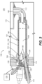
- FIG. 2 Some examples of the interior surfaces of the torch ignitor 101 where carbon growth can be mitigated with the self-cleaning cycle are labeled in Fig. 2 . These include: surfaces 132 internal to the fuel nozzle 108, external surfaces 134 of the fuel nozzle 108, on a nozzle tip 136 of the fuel nozzle 108, on a dome surface 138 of the combustion chamber 104, on a combustor liner surface 140 of the combustion chamber 104, in interior surface 142 of an exhaust tube 112, and/or on glow plug surfaces 144 in the combustion chamber 104.
Landscapes
- Engineering & Computer Science (AREA)
- Chemical & Material Sciences (AREA)
- Combustion & Propulsion (AREA)
- Mechanical Engineering (AREA)
- General Engineering & Computer Science (AREA)
- Combustion Methods Of Internal-Combustion Engines (AREA)
Abstract
Description
- The present disclosure relates to continuous ignition systems, and more particularly to torch ignitors for lighting and relighting gas turbine engines.
- A small, independent torch igniter system offers many advantages for gas turbine engines. As the torch device can operate in a fuel rich mixture, there is a potential that carbon can develop in a variety of locations such as internal to the fuel nozzle, on the nozzle tip, on the dome surface, on the combustor liner surface, and on the glow plug surfaces. This carbon growth can also occur as a function of shutdown of the torch, where fuel can drip, stagnant fuel can sit within the injector and torch, and evaporated fuel can condense on cooler surfaces. If this carbon is allowed to grow uncontrolled, it could potentially block fuel spray deteriorating performance, or large clumps of carbon can break off which could potentially plug circuits within the torch, and/or cause erosion to downstream components. So maintenance of torch devices is needed to avoid excessive carbon growth.
- The conventional techniques have been considered satisfactory for their intended purpose. However, there is an ever present need for improved systems and methods for maintenance of torch devices for continuous combustion. This disclosure provides a solution for this need.
- A method of operating and cleaning a torch ignitor for continuous ignition includes issuing a fuel-lean flow through a combustion chamber of a torch ignitor. The method also includes heating interior surfaces of the torch ignitor, wherein the fuel-lean flow reacts with carbon deposits on the interior surfaces to remove the carbon deposits.
- Issuing the fuel-lean flow and heating the interior surfaces can be performed as a self-cleaning cycle intermittently during flight. The method can include issuing an air fuel mixture into the combustion chamber that has a higher fuel air ratio than the fuel-lean flow, intermittently between the self-cleaning cycles. Issuing the air fuel mixture into the combustion chamber that has a higher fuel air ratio than the fuel-lean flow can include issuing a flame from the combustion chamber of the torch ignitor into a combustion space of a main combustor of a gas turbine engine.
- Issuing the flame from the combustion chamber of the torch ignitor into the combustion space of a main combustor of a gas turbine engine can be performed while sustaining combustion within the combustor of the gas turbine engine while issuing the flame from the torch ignitor into the main combustor. Sustaining combustion within the combustor of the gas turbine engine can include powering a turbine section of the gas turbine engine using combustion products from the combustor, and driving a compressor section of the gas turbine engine with the turbine section to supply compressed air to the combustor for combustion.
- The method can include issuing an air fuel mixture into the combustion chamber that is richer than the fuel-lean flow both before and after issuing the fuel-lean flow through the combustion chamber. Issuing a fuel-lean flow through the combustion chamber can include turning down fuel flow while maintaining air flow issued into the combustion chamber to lower the fuel to air ratio.
- Issuing the fuel-lean flow and heating the interior surfaces can be performed as a self-cleaning cycle as part of an engine shutdown process. The method can include shutting down an engine to which the torch ignitor is operatively connected. Issuing the fuel-lean flow and heating the interior surfaces can be performed during a maintenance cycle on an engine while the engine is out of service for maintenance.
- Heating interior surfaces of the torch ignitor can include energizing an ignitor within the combustion chamber. Issuing a fuel-lean flow can include issuing air into the combustion chamber without issuing fuel into the combustion chamber. Heating interior surfaces of the torch ignitor can include sustaining combustion within the combustion chamber by issuing a fuel lean mixture of fuel and air into the combustion chamber.
- Issuing a fuel-lean flow and heating interior surface can be performed in a torch ignitor in a gas turbine engine while the gas turbine engine is on an aircraft. Issuing the fuel-lean flow can include issuing air into the combustion chamber of the torch ignitor from a compressed air source separate from a main compressor of a gas turbine engine. Issuing the fuel-lean flow can include issuing air into the combustion chamber of the torch ignitor from a compressor section of a gas turbine engine.
- Issuing the fuel-lean flow can include issuing oxygen gas in a mixture with less than 79% nitrogen into the combustion chamber of the torch ignitor. Issuing the fuel-lean flow and heating interior surfaces can be performed for a period of time sufficient to remove carbon build up on the interior surfaces built up since a previous cycle of issuing the fuel-lean flow and heating interior surfaces.
- The interior surfaces can include at least one of: internal to a fuel nozzle of the torch ignitor, external surfaces of the fuel nozzle, on a nozzle tip of the fuel nozzle, on a dome surface of the combustion chamber, on a combustor liner surface of the combustion chamber, in interior surface of an exhaust tube of the combustion chamber, and/or on glow plug surfaces in the combustion chamber.
- These and other features of the systems and methods of the subject disclosure will become more readily apparent to those skilled in the art from the following detailed description of the preferred embodiments taken in conjunction with the drawings.
- So that those skilled in the art to which the subject disclosure appertains will readily understand how to make and use the devices and methods of the subject disclosure without undue experimentation, preferred embodiments thereof will be described in detail herein below with reference to certain figures, wherein:
-
Fig. 1 is a schematic cross-sectional side elevation view of an embodiment of a system constructed in accordance with the present disclosure, showing the torch ignitor installed in a gas turbine engine for continuous ignition; and -
Fig. 2 is a schematic cross-sectional side elevation view of the torch ignitor ofFig. 1 , showing interior surfaces of the torch ignitor where carbon deposits can be removed by fuel-lean heating. - Reference will now be made to the drawings wherein like reference numerals identify similar structural features or aspects of the subject disclosure. For purposes of explanation and illustration, and not limitation, a partial view of an embodiment of a system in accordance with the disclosure is shown in
Fig. 1 and is designated generally byreference character 100. Other embodiments of systems in accordance with the disclosure, or aspects thereof, are provided inFig. 2 as will be described. The systems and methods described herein can be used to reduce and/or remove carbon deposits from surfaces of torch ignitors for continuous ignition in gas turbine engines. - The
torch ignitor system 100 includes atorch ignitor 101 having atorch wall 102. Thetorch wall 102 defines acombustion chamber 104 therein with aflame outlet 106 passing out of thetorch wall 102 downstream of thecombustion chamber 104. Afuel nozzle 108 is mounted to thetorch wall 102 to issue fuel into thecombustion chamber 104. At least oneignitor 110 is mounted to thetorch wall 102, positioned to ignite fuel issued from thefuel nozzle 108. An exhaust oroutlet tube 112 is in fluid communication with thecombustion chamber 104 extending downstream from theflame outlet 106. - The
torch wall 102 is mounted to anengine case 114 of a gas turbine engine. Acombustor 116 is included within theengine case 114, e.g. for receiving compressor discharge air from an upstream compressor (not shown but thediffuser 118 of the compressor is labeled inFig. 1 ), combusting fuel in the compressor discharge air, and issuing combustion products to a downstream turbine, theinlet 119 of which is labeled inFig. 1 . Theflame outlet 106 is mounted in fluid communication, throughoutlet tube 112, with aninterior combustion space 120 of thecombustor 116. Thecombustor 116 is spaced apart from thecombustion chamber 104 of thetorch wall 102, so at start up or in the event of a flame out in themain combustion space 120, a flame from thecombustion chamber 104 can issue through theoutlet tube 112 and into thecombustion space 120 to light or relight thecombustor 116. - The
torch combustion chamber 104 is mostly isolated from themain combustor 116. Thenarrow outlet tube 112 acts as an isolator which limits communication between the two volumes. This isolation allows thetorch combustion chamber 104 to be stable while themain combustor 116 could have strong pressure oscillations which happen during ignition, blowout, acoustic instabilities, and the like. Thetorch combustion chamber 104 is also generally sheltered from the main combustor flow field so recirculation patterns, high velocity zones, and the like do not make their way up into thetorch combustion chamber 104. - A
mounting flange 122 extends from thetorch wall 102 and is mounted to theengine case 114. Theignitors 110 extend from outside theengine case 114, through themounting flange 122 and into thecombustion chamber 104 for igniting a mixture of fuel and air from thefuel nozzle 108 to start up thetorch ignitor system 100. Thefuel nozzle 108 is mounted on an opposite side of theflange 122 from thecombustion chamber 104. - The
torch ignitor 101 is in addition to a plurality ofmain fuel injectors 109 extending through thecase 114 and connecting to thecombustor 116 for injection of fuel and air into thecombustion space 120. Only twomain fuel injectors 109 are shown in the annular cross-section ofFig. 1 , however those skilled in the art will readily appreciate that any suitable number ofmain fuel injectors 109 can be included. - With reference now to
Fig. 2 , a method of operating and cleaning atorch ignitor 101 for continuous ignition includes issuing a fuel-lean flow from thenozzle 108 through acombustion chamber 104. The method also includes heating interior surfaces of thetorch ignitor 101, wherein the fuel-lean flow reacts with carbon deposits on the interior surfaces to remove the carbon deposits. - Issuing the fuel-lean flow and heating the interior surfaces can be performed as a self-cleaning cycle intermittently during flight, or if the
torch ignitor 101 is on a ground-operated gas turbine engine, the self-cleaning cycle can be run intermittently during normal operation. The method includes issuing an air fuel mixture into the combustion chamber that has a higher fuel air ratio than the fuel-lean flow. This higher fuel air ratio flow can be issued intermittently between the self-cleaning cycles. Issuing the air fuel mixture into the combustion chamber at the higher fuel air ratio includes issuing a flame from thecombustion chamber 104 of thetorch ignitor 101 into acombustion space 120 of amain combustor 116 of a gas turbine engine. - Issuing the flame from the
combustion chamber 104 of thetorch ignitor 101 into thecombustion space 120 of themain combustor 116 is performed while sustaining combustion within thecombustor 116 of the gas turbine engine, while issuing the flame from thetorch ignitor 101 into themain combustor 116. Sustaining combustion within thecombustor 116 includes powering a turbine section, theinlet 119 of which is labeled inFig. 1 , using combustion products from thecombustor 116, and driving a compressor section (thediffuser outlet 118 of which is indicated inFig. 1 ) with the turbine section to supply compressed air to thecombustor 116 for combustion. - The method includes issuing an air fuel mixture from the
fuel nozzle 108 into thecombustion chamber 104 that is richer than the fuel-lean flow both before and after issuing the fuel-lean flow through thecombustion chamber 104. Issuing a fuel-lean flow through thecombustion chamber 104 includes turning down fuel flow while maintaining air flow issued from thenozzle 108 into thecombustion chamber 104 to lower the fuel to air ratio. - It is also contemplated that in addition to or in lieu of intermittent cleaning cycles during normal engine operation, issuing the fuel-lean flow and heating the interior surfaces can be performed as a self-cleaning cycle as part of an engine shutdown process. This method includes shutting down the gas turbine engine to which the
torch ignitor 101 is operatively connected. It is also contemplated that issuing the fuel-lean flow and heating the interior surfaces can be performed during a maintenance cycle on an engine while the engine is out of service for maintenance. For engines on aircraft, the self-cleaning cycles can be run with the engine "on wing" whether the engine is actually located on the wing of the aircraft or elsewhere. - One way of heating the interior surfaces of the
torch ignitor 101 in the self-cleaning process includes energizing one or more of theignitor 110 within thecombustion chamber 104. In this technique, issuing a fuel-lean flow includes issuing air into thecombustion chamber 104 without issuing fuel into thecombustion chamber 104. It is also contemplated that heating the interior surfaces of thetorch ignitor 101 can include sustaining combustion within the combustion chamber by issuing a fuel lean mixture of fuel and air into thecombustion chamber 104 fromnozzle 108. - Issuing the fuel-lean flow can include issuing compressor discharge air into the
combustion chamber 104 of thetorch ignitor 101 from the main compressor, theoutlet 118 of which is indicated inFig. 1 , or from acompressed air source 130 separate from a main compressor. It is also contemplated that instead of using compressed air, a compressed flow of oxygen gas can be used as the oxidant for the self-cleaning cycle. For this purpose, oxygen gas can be any gas mixture with more than 21% oxygen and less than 79% nitrogen. The self-cleaning cycle can be performed for a period of time sufficient to remove carbon build up on the interior surfaces that has built up since a previous self-cleaning cycle, thus maintaining the carbon build up levels below an acceptable operational limit. - Some examples of the interior surfaces of the
torch ignitor 101 where carbon growth can be mitigated with the self-cleaning cycle are labeled inFig. 2 . These include:surfaces 132 internal to thefuel nozzle 108,external surfaces 134 of thefuel nozzle 108, on anozzle tip 136 of thefuel nozzle 108, on adome surface 138 of thecombustion chamber 104, on acombustor liner surface 140 of thecombustion chamber 104, ininterior surface 142 of anexhaust tube 112, and/or on glow plug surfaces 144 in thecombustion chamber 104. - Potential benefits of systems and methods as disclosed herein include self-cleaning cycles that allow the torch system to remain on wing longer and prevents erosion of downstream components. The methods and systems of the present disclosure, as described above and shown in the drawings, provide for reducing and/or removing carbon deposits from surfaces of torch ignitors for continuous ignition in gas turbine engines. While the apparatus and methods of the subject disclosure have been shown and described with reference to preferred embodiments, those skilled in the art will readily appreciate that changes and/or modifications may be made thereto without departing from the scope of the subject disclosure.
Claims (15)
- A method of operating and cleaning a torch ignitor (101) for continuous ignition comprising:issuing a fuel-lean flow through a combustion chamber (104) of a torch ignitor (101); andheating interior surfaces of the torch ignitor (101), wherein the fuel-lean flow reacts with carbon deposits on the interior surfaces to remove the carbon deposits.
- The method as recited in claim 1, wherein the torch ignitor (101) is aboard an aircraft and wherein issuing the fuel-lean flow and heating the interior surfaces are performed as a self-cleaning cycle intermittently during flight of the aircraft.
- The method as recited in claim 2, wherein the self-cleaning cycles is repeated as a series of self-cleaning cycles and further comprising issuing an air fuel mixture into the combustion chamber (104) that has a higher fuel air ratio than the fuel-lean flow, intermittently between the self-cleaning cycles.
- The method as recited in claim 3, wherein issuing the air fuel mixture into the combustion chamber that has a higher fuel air ratio than the fuel-lean flow includes issuing a flame from the combustion chamber (104) of the torch ignitor (101) into a combustion space (120) of a main combustor (116) of a gas turbine engine of the aircraft.
- The method as recited in claim 4, wherein issuing the flame from the combustion chamber (104) of the torch ignitor (101) into the combustion space (120) of a main combustor (116)_of a gas turbine engine is performed while sustaining combustion within the combustor (116) of the gas turbine engine while issuing the flame from the torch ignitor (101) into the main combustor (116), and optionally
wherein sustaining combustion within the combustor (116) of the gas turbine engine includes:powering a turbine section of the gas turbine engine using combustion products from the combustor (116); anddriving a compressor section of the gas turbine engine with the turbine section to supply compressed air to the combustor (116). - The method as recited in any of claims 2 to 5, further comprising:prior to issuing the fuel-lean flow through the combustion chamber (104), issuing an air fuel mixture into the combustion chamber (104) that is richer than the fuel-lean flow; andafter issuing the fuel-lean flow through the combustion chamber (104), resuming issuing the air fuel mixture that is richer than the fuel-lean flow into the combustion chamber (104).
- The method as recited in any of claims 2 to 6, wherein issuing the fuel-lean flow and heating the interior surfaces are performed as a self-cleaning cycle as part of an engine shutdown process, and optionally
the method further comprising shutting down an engine to which the torch ignitor (101) is operatively connected. - The method as recited in any preceding claim, wherein issuing the fuel-lean flow and heating the interior surfaces are performed during a maintenance cycle on an engine while the engine is out of service for maintenance.
- The method as recited in any preceding claim, wherein heating interior surfaces of the torch ignitor includes energizing an ignitor within the combustion chamber, and/or
wherein issuing a fuel-lean flow includes issuing air into the combustion chamber without issuing fuel into the combustion chamber. - The method as recited in any preceding claim, wherein heating interior surfaces of the torch ignitor (101) includes sustaining combustion within the combustion chamber (104) by issuing a fuel lean mixture of fuel and air into the combustion chamber (104), and/or
wherein issuing a fuel-lean flow and heating interior surface are performed in a torch ignitor (101) in a gas turbine engine while the gas turbine engine is on an aircraft. - The method as recited in any preceding claim 1, wherein issuing the fuel-lean flow includes issuing air into the combustion chamber (104) of the torch ignitor (101) from a compressed air source (130) separate from a main compressor of a gas turbine engine, or
wherein issuing the fuel-lean flow includes issuing air into the combustion chamber (104) of the torch ignitor (101) from a compressor section of a gas turbine engine. - The method as recited in any preceding claim, wherein issuing the fuel-lean flow includes issuing oxygen gas in a mixture with less than 79% nitrogen into the combustion chamber (104) of the torch ignitor (101).
- The method as recited in any preceding claim, wherein issuing the fuel-lean flow and heating interior surfaces is performed for a period of time sufficient to remove carbon build up on the interior surfaces built up since a previous cycle of issuing the fuel-lean flow and heating interior surfaces.
- The method as recited in any preceding claim, wherein the interior surfaces include at least one of: internal (132) to a fuel nozzle (108) of the torch ignitor, external surfaces (134) of the fuel nozzle (108), on a nozzle tip (136) of the fuel nozzle (108), on a dome surface (138) of the combustion chamber (104) , on a combustor liner surface (140) of the combustion chamber (104), in interior surface (142) of an exhaust tube (112) of the combustion chamber (104), and/or on glow plug surfaces (144) in the combustion chamber (104).
- The method as recited in any preceding claim, wherein issuing a fuel-lean flow through the combustion chamber (104) includes turning down fuel flow while maintaining air flow issued into the combustion chamber (104) to lower the fuel to air ratio.
Applications Claiming Priority (1)
| Application Number | Priority Date | Filing Date | Title |
|---|---|---|---|
| US17/460,755 US20230060569A1 (en) | 2021-08-30 | 2021-08-30 | Self-cleaning for torch ignitors |
Publications (2)
| Publication Number | Publication Date |
|---|---|
| EP4141324A1 true EP4141324A1 (en) | 2023-03-01 |
| EP4141324B1 EP4141324B1 (en) | 2024-06-26 |
Family
ID=83151853
Family Applications (1)
| Application Number | Title | Priority Date | Filing Date |
|---|---|---|---|
| EP22192552.2A Active EP4141324B1 (en) | 2021-08-30 | 2022-08-29 | Method of operating and cleaning a torch ignitor |
Country Status (2)
| Country | Link |
|---|---|
| US (1) | US20230060569A1 (en) |
| EP (1) | EP4141324B1 (en) |
Families Citing this family (2)
| Publication number | Priority date | Publication date | Assignee | Title |
|---|---|---|---|---|
| US11421601B2 (en) * | 2019-03-28 | 2022-08-23 | Woodward, Inc. | Second stage combustion for igniter |
| CN116209823A (en) | 2020-06-23 | 2023-06-02 | 伍德沃德有限公司 | Ignition system for power generating engine |
Citations (5)
| Publication number | Priority date | Publication date | Assignee | Title |
|---|---|---|---|---|
| US2890569A (en) * | 1954-05-03 | 1959-06-16 | Phillips Petroleum Co | Removal of carbon deposits in jet engines |
| US4242863A (en) * | 1978-03-16 | 1981-01-06 | Caterpillar Tractor Co. | Dual phase fuel vaporizing combustor |
| US20110173982A1 (en) * | 2005-01-14 | 2011-07-21 | Lev Alexander Prociw | Gas turbine engine fuel conveying member |
| EP2813683A1 (en) * | 2013-06-13 | 2014-12-17 | Delavan Inc. | Continuous ignition systems |
| US20160047318A1 (en) * | 2014-08-18 | 2016-02-18 | Woodward, Inc. | Torch Igniter |
Family Cites Families (7)
| Publication number | Priority date | Publication date | Assignee | Title |
|---|---|---|---|---|
| US4860533A (en) * | 1987-09-17 | 1989-08-29 | Prutech Ii | Torch igniter for a combustor having U.V. flame detection |
| US6871792B2 (en) * | 2002-03-22 | 2005-03-29 | Chrysalis Technologies Incorporated | Apparatus and method for preparing and delivering fuel |
| US8966879B1 (en) * | 2012-02-15 | 2015-03-03 | Orbital Technologies Corporation | Acoustic igniter |
| US9476399B1 (en) * | 2012-05-16 | 2016-10-25 | Orbital Technologies Corporation | Glow plug type acoustic resonance igniter |
| US11702955B2 (en) * | 2019-01-14 | 2023-07-18 | General Electric Company | Component repair system and method |
| US11421601B2 (en) * | 2019-03-28 | 2022-08-23 | Woodward, Inc. | Second stage combustion for igniter |
| US11578661B2 (en) * | 2019-09-19 | 2023-02-14 | Pratt & Whitney Canada Corp. | Systems and methods for starting a gas turbine engine |
-
2021
- 2021-08-30 US US17/460,755 patent/US20230060569A1/en active Pending
-
2022
- 2022-08-29 EP EP22192552.2A patent/EP4141324B1/en active Active
Patent Citations (5)
| Publication number | Priority date | Publication date | Assignee | Title |
|---|---|---|---|---|
| US2890569A (en) * | 1954-05-03 | 1959-06-16 | Phillips Petroleum Co | Removal of carbon deposits in jet engines |
| US4242863A (en) * | 1978-03-16 | 1981-01-06 | Caterpillar Tractor Co. | Dual phase fuel vaporizing combustor |
| US20110173982A1 (en) * | 2005-01-14 | 2011-07-21 | Lev Alexander Prociw | Gas turbine engine fuel conveying member |
| EP2813683A1 (en) * | 2013-06-13 | 2014-12-17 | Delavan Inc. | Continuous ignition systems |
| US20160047318A1 (en) * | 2014-08-18 | 2016-02-18 | Woodward, Inc. | Torch Igniter |
Also Published As
| Publication number | Publication date |
|---|---|
| US20230060569A1 (en) | 2023-03-02 |
| EP4141324B1 (en) | 2024-06-26 |
Similar Documents
| Publication | Publication Date | Title |
|---|---|---|
| EP3948083B1 (en) | Staged igniter for a gas turbine combustor and method of operataing the same | |
| EP4019838B1 (en) | Torch ignitor sytem for a combustor of a gas turbine engine and method of operating the same | |
| CN106796031B (en) | Torch type igniter | |
| US8607575B2 (en) | Method and apparatus for actively controlling fuel flow to a mixer assembly of a gas turbine engine combustor | |
| EP2813684B1 (en) | Continuous ignition | |
| US8377232B2 (en) | On-line cleaning of turbine hot gas path deposits via pressure pulsations | |
| US8082724B2 (en) | Combusting system, remodeling method for combusting system, and fuel injection method for combusting system | |
| US4463568A (en) | Fuel injector for gas turbine engines | |
| EP4166849A1 (en) | Pyrolytic cleaning of combustors | |
| NO321264B1 (en) | Method and apparatus for reducing gas turbine emissions | |
| EP4141324B1 (en) | Method of operating and cleaning a torch ignitor | |
| EP4113009B1 (en) | Torch ignitor for a gas turbine engine | |
| CA2516753C (en) | Methods and apparatus for reducing gas turbine engine emissions | |
| EP4166847A1 (en) | Fuel injectors with torch ignitors | |
| EP4141325A1 (en) | Cooling for surface ignitors in torch ignition devices | |
| CA2595061A1 (en) | Method and apparatus for actively controlling fuel flow to a mixer assembly of a gas turbine engine combustor | |
| US4063872A (en) | Universal burner | |
| JPH04324028A (en) | Gas firing combustion apparatus | |
| RU95103644A (en) | Device for feeding fuel to combustion chamber of gas-turbine engine |
Legal Events
| Date | Code | Title | Description |
|---|---|---|---|
| PUAI | Public reference made under article 153(3) epc to a published international application that has entered the european phase |
Free format text: ORIGINAL CODE: 0009012 |
|
| STAA | Information on the status of an ep patent application or granted ep patent |
Free format text: STATUS: THE APPLICATION HAS BEEN PUBLISHED |
|
| AK | Designated contracting states |
Kind code of ref document: A1 Designated state(s): AL AT BE BG CH CY CZ DE DK EE ES FI FR GB GR HR HU IE IS IT LI LT LU LV MC MK MT NL NO PL PT RO RS SE SI SK SM TR |
|
| STAA | Information on the status of an ep patent application or granted ep patent |
Free format text: STATUS: REQUEST FOR EXAMINATION WAS MADE |
|
| 17P | Request for examination filed |
Effective date: 20230831 |
|
| RBV | Designated contracting states (corrected) |
Designated state(s): AL AT BE BG CH CY CZ DE DK EE ES FI FR GB GR HR HU IE IS IT LI LT LU LV MC MK MT NL NO PL PT RO RS SE SI SK SM TR |
|
| P01 | Opt-out of the competence of the unified patent court (upc) registered |
Effective date: 20230922 |
|
| GRAP | Despatch of communication of intention to grant a patent |
Free format text: ORIGINAL CODE: EPIDOSNIGR1 |
|
| STAA | Information on the status of an ep patent application or granted ep patent |
Free format text: STATUS: GRANT OF PATENT IS INTENDED |
|
| INTG | Intention to grant announced |
Effective date: 20240119 |
|
| GRAS | Grant fee paid |
Free format text: ORIGINAL CODE: EPIDOSNIGR3 |
|
| GRAA | (expected) grant |
Free format text: ORIGINAL CODE: 0009210 |
|
| STAA | Information on the status of an ep patent application or granted ep patent |
Free format text: STATUS: THE PATENT HAS BEEN GRANTED |
|
| AK | Designated contracting states |
Kind code of ref document: B1 Designated state(s): AL AT BE BG CH CY CZ DE DK EE ES FI FR GB GR HR HU IE IS IT LI LT LU LV MC MK MT NL NO PL PT RO RS SE SI SK SM TR |
|
| REG | Reference to a national code |
Ref country code: GB Ref legal event code: FG4D |
|
| REG | Reference to a national code |
Ref country code: CH Ref legal event code: EP |
|
| REG | Reference to a national code |
Ref country code: DE Ref legal event code: R096 Ref document number: 602022004133 Country of ref document: DE |
|
| PG25 | Lapsed in a contracting state [announced via postgrant information from national office to epo] |
Ref country code: BG Free format text: LAPSE BECAUSE OF FAILURE TO SUBMIT A TRANSLATION OF THE DESCRIPTION OR TO PAY THE FEE WITHIN THE PRESCRIBED TIME-LIMIT Effective date: 20240626 |
|
| PG25 | Lapsed in a contracting state [announced via postgrant information from national office to epo] |
Ref country code: FI Free format text: LAPSE BECAUSE OF FAILURE TO SUBMIT A TRANSLATION OF THE DESCRIPTION OR TO PAY THE FEE WITHIN THE PRESCRIBED TIME-LIMIT Effective date: 20240626 Ref country code: HR Free format text: LAPSE BECAUSE OF FAILURE TO SUBMIT A TRANSLATION OF THE DESCRIPTION OR TO PAY THE FEE WITHIN THE PRESCRIBED TIME-LIMIT Effective date: 20240626 |
|
| REG | Reference to a national code |
Ref country code: LT Ref legal event code: MG9D |
|
| PG25 | Lapsed in a contracting state [announced via postgrant information from national office to epo] |
Ref country code: GR Free format text: LAPSE BECAUSE OF FAILURE TO SUBMIT A TRANSLATION OF THE DESCRIPTION OR TO PAY THE FEE WITHIN THE PRESCRIBED TIME-LIMIT Effective date: 20240927 |
|
| PG25 | Lapsed in a contracting state [announced via postgrant information from national office to epo] |
Ref country code: LV Free format text: LAPSE BECAUSE OF FAILURE TO SUBMIT A TRANSLATION OF THE DESCRIPTION OR TO PAY THE FEE WITHIN THE PRESCRIBED TIME-LIMIT Effective date: 20240626 |
|
| REG | Reference to a national code |
Ref country code: NL Ref legal event code: MP Effective date: 20240626 |
|
| PG25 | Lapsed in a contracting state [announced via postgrant information from national office to epo] |
Ref country code: NO Free format text: LAPSE BECAUSE OF FAILURE TO SUBMIT A TRANSLATION OF THE DESCRIPTION OR TO PAY THE FEE WITHIN THE PRESCRIBED TIME-LIMIT Effective date: 20240926 Ref country code: LV Free format text: LAPSE BECAUSE OF FAILURE TO SUBMIT A TRANSLATION OF THE DESCRIPTION OR TO PAY THE FEE WITHIN THE PRESCRIBED TIME-LIMIT Effective date: 20240626 Ref country code: HR Free format text: LAPSE BECAUSE OF FAILURE TO SUBMIT A TRANSLATION OF THE DESCRIPTION OR TO PAY THE FEE WITHIN THE PRESCRIBED TIME-LIMIT Effective date: 20240626 Ref country code: GR Free format text: LAPSE BECAUSE OF FAILURE TO SUBMIT A TRANSLATION OF THE DESCRIPTION OR TO PAY THE FEE WITHIN THE PRESCRIBED TIME-LIMIT Effective date: 20240927 Ref country code: FI Free format text: LAPSE BECAUSE OF FAILURE TO SUBMIT A TRANSLATION OF THE DESCRIPTION OR TO PAY THE FEE WITHIN THE PRESCRIBED TIME-LIMIT Effective date: 20240626 Ref country code: BG Free format text: LAPSE BECAUSE OF FAILURE TO SUBMIT A TRANSLATION OF THE DESCRIPTION OR TO PAY THE FEE WITHIN THE PRESCRIBED TIME-LIMIT Effective date: 20240626 Ref country code: RS Free format text: LAPSE BECAUSE OF FAILURE TO SUBMIT A TRANSLATION OF THE DESCRIPTION OR TO PAY THE FEE WITHIN THE PRESCRIBED TIME-LIMIT Effective date: 20240926 |
|
| PG25 | Lapsed in a contracting state [announced via postgrant information from national office to epo] |
Ref country code: NL Free format text: LAPSE BECAUSE OF FAILURE TO SUBMIT A TRANSLATION OF THE DESCRIPTION OR TO PAY THE FEE WITHIN THE PRESCRIBED TIME-LIMIT Effective date: 20240626 |
|
| REG | Reference to a national code |
Ref country code: AT Ref legal event code: MK05 Ref document number: 1697994 Country of ref document: AT Kind code of ref document: T Effective date: 20240626 |
|
| PG25 | Lapsed in a contracting state [announced via postgrant information from national office to epo] |
Ref country code: NL Free format text: LAPSE BECAUSE OF FAILURE TO SUBMIT A TRANSLATION OF THE DESCRIPTION OR TO PAY THE FEE WITHIN THE PRESCRIBED TIME-LIMIT Effective date: 20240626 |
|
| PG25 | Lapsed in a contracting state [announced via postgrant information from national office to epo] |
Ref country code: PT Free format text: LAPSE BECAUSE OF FAILURE TO SUBMIT A TRANSLATION OF THE DESCRIPTION OR TO PAY THE FEE WITHIN THE PRESCRIBED TIME-LIMIT Effective date: 20241028 |
|
| PG25 | Lapsed in a contracting state [announced via postgrant information from national office to epo] |
Ref country code: PT Free format text: LAPSE BECAUSE OF FAILURE TO SUBMIT A TRANSLATION OF THE DESCRIPTION OR TO PAY THE FEE WITHIN THE PRESCRIBED TIME-LIMIT Effective date: 20241028 |
|
| PG25 | Lapsed in a contracting state [announced via postgrant information from national office to epo] |
Ref country code: PL Free format text: LAPSE BECAUSE OF FAILURE TO SUBMIT A TRANSLATION OF THE DESCRIPTION OR TO PAY THE FEE WITHIN THE PRESCRIBED TIME-LIMIT Effective date: 20240626 |
|
| PG25 | Lapsed in a contracting state [announced via postgrant information from national office to epo] |
Ref country code: EE Free format text: LAPSE BECAUSE OF FAILURE TO SUBMIT A TRANSLATION OF THE DESCRIPTION OR TO PAY THE FEE WITHIN THE PRESCRIBED TIME-LIMIT Effective date: 20240626 |
|
| PG25 | Lapsed in a contracting state [announced via postgrant information from national office to epo] |
Ref country code: AT Free format text: LAPSE BECAUSE OF FAILURE TO SUBMIT A TRANSLATION OF THE DESCRIPTION OR TO PAY THE FEE WITHIN THE PRESCRIBED TIME-LIMIT Effective date: 20240626 Ref country code: IS Free format text: LAPSE BECAUSE OF FAILURE TO SUBMIT A TRANSLATION OF THE DESCRIPTION OR TO PAY THE FEE WITHIN THE PRESCRIBED TIME-LIMIT Effective date: 20241026 |
|
| PG25 | Lapsed in a contracting state [announced via postgrant information from national office to epo] |
Ref country code: CZ Free format text: LAPSE BECAUSE OF FAILURE TO SUBMIT A TRANSLATION OF THE DESCRIPTION OR TO PAY THE FEE WITHIN THE PRESCRIBED TIME-LIMIT Effective date: 20240626 |
|
| PG25 | Lapsed in a contracting state [announced via postgrant information from national office to epo] |
Ref country code: RO Free format text: LAPSE BECAUSE OF FAILURE TO SUBMIT A TRANSLATION OF THE DESCRIPTION OR TO PAY THE FEE WITHIN THE PRESCRIBED TIME-LIMIT Effective date: 20240626 Ref country code: SK Free format text: LAPSE BECAUSE OF FAILURE TO SUBMIT A TRANSLATION OF THE DESCRIPTION OR TO PAY THE FEE WITHIN THE PRESCRIBED TIME-LIMIT Effective date: 20240626 |
|
| PG25 | Lapsed in a contracting state [announced via postgrant information from national office to epo] |
Ref country code: SM Free format text: LAPSE BECAUSE OF FAILURE TO SUBMIT A TRANSLATION OF THE DESCRIPTION OR TO PAY THE FEE WITHIN THE PRESCRIBED TIME-LIMIT Effective date: 20240626 Ref country code: ES Free format text: LAPSE BECAUSE OF FAILURE TO SUBMIT A TRANSLATION OF THE DESCRIPTION OR TO PAY THE FEE WITHIN THE PRESCRIBED TIME-LIMIT Effective date: 20240626 |
|
| PG25 | Lapsed in a contracting state [announced via postgrant information from national office to epo] |
Ref country code: SM Free format text: LAPSE BECAUSE OF FAILURE TO SUBMIT A TRANSLATION OF THE DESCRIPTION OR TO PAY THE FEE WITHIN THE PRESCRIBED TIME-LIMIT Effective date: 20240626 Ref country code: SK Free format text: LAPSE BECAUSE OF FAILURE TO SUBMIT A TRANSLATION OF THE DESCRIPTION OR TO PAY THE FEE WITHIN THE PRESCRIBED TIME-LIMIT Effective date: 20240626 Ref country code: RO Free format text: LAPSE BECAUSE OF FAILURE TO SUBMIT A TRANSLATION OF THE DESCRIPTION OR TO PAY THE FEE WITHIN THE PRESCRIBED TIME-LIMIT Effective date: 20240626 Ref country code: PL Free format text: LAPSE BECAUSE OF FAILURE TO SUBMIT A TRANSLATION OF THE DESCRIPTION OR TO PAY THE FEE WITHIN THE PRESCRIBED TIME-LIMIT Effective date: 20240626 Ref country code: IS Free format text: LAPSE BECAUSE OF FAILURE TO SUBMIT A TRANSLATION OF THE DESCRIPTION OR TO PAY THE FEE WITHIN THE PRESCRIBED TIME-LIMIT Effective date: 20241026 Ref country code: ES Free format text: LAPSE BECAUSE OF FAILURE TO SUBMIT A TRANSLATION OF THE DESCRIPTION OR TO PAY THE FEE WITHIN THE PRESCRIBED TIME-LIMIT Effective date: 20240626 Ref country code: EE Free format text: LAPSE BECAUSE OF FAILURE TO SUBMIT A TRANSLATION OF THE DESCRIPTION OR TO PAY THE FEE WITHIN THE PRESCRIBED TIME-LIMIT Effective date: 20240626 Ref country code: CZ Free format text: LAPSE BECAUSE OF FAILURE TO SUBMIT A TRANSLATION OF THE DESCRIPTION OR TO PAY THE FEE WITHIN THE PRESCRIBED TIME-LIMIT Effective date: 20240626 Ref country code: AT Free format text: LAPSE BECAUSE OF FAILURE TO SUBMIT A TRANSLATION OF THE DESCRIPTION OR TO PAY THE FEE WITHIN THE PRESCRIBED TIME-LIMIT Effective date: 20240626 |
|
| PG25 | Lapsed in a contracting state [announced via postgrant information from national office to epo] |
Ref country code: IT Free format text: LAPSE BECAUSE OF FAILURE TO SUBMIT A TRANSLATION OF THE DESCRIPTION OR TO PAY THE FEE WITHIN THE PRESCRIBED TIME-LIMIT Effective date: 20240626 |
|
| REG | Reference to a national code |
Ref country code: DE Ref legal event code: R097 Ref document number: 602022004133 Country of ref document: DE |
|
| PG25 | Lapsed in a contracting state [announced via postgrant information from national office to epo] |
Ref country code: DK Free format text: LAPSE BECAUSE OF FAILURE TO SUBMIT A TRANSLATION OF THE DESCRIPTION OR TO PAY THE FEE WITHIN THE PRESCRIBED TIME-LIMIT Effective date: 20240626 |
|
| PG25 | Lapsed in a contracting state [announced via postgrant information from national office to epo] |
Ref country code: LU Free format text: LAPSE BECAUSE OF NON-PAYMENT OF DUE FEES Effective date: 20240829 |
|
| PG25 | Lapsed in a contracting state [announced via postgrant information from national office to epo] |
Ref country code: MC Free format text: LAPSE BECAUSE OF FAILURE TO SUBMIT A TRANSLATION OF THE DESCRIPTION OR TO PAY THE FEE WITHIN THE PRESCRIBED TIME-LIMIT Effective date: 20240626 |
|
| PLBE | No opposition filed within time limit |
Free format text: ORIGINAL CODE: 0009261 |
|
| STAA | Information on the status of an ep patent application or granted ep patent |
Free format text: STATUS: NO OPPOSITION FILED WITHIN TIME LIMIT |
|
| 26N | No opposition filed |
Effective date: 20250327 |
|
| REG | Reference to a national code |
Ref country code: BE Ref legal event code: MM Effective date: 20240831 |
|
| PG25 | Lapsed in a contracting state [announced via postgrant information from national office to epo] |
Ref country code: BE Free format text: LAPSE BECAUSE OF NON-PAYMENT OF DUE FEES Effective date: 20240831 |
|
| PG25 | Lapsed in a contracting state [announced via postgrant information from national office to epo] |
Ref country code: IE Free format text: LAPSE BECAUSE OF NON-PAYMENT OF DUE FEES Effective date: 20240829 |
|
| PG25 | Lapsed in a contracting state [announced via postgrant information from national office to epo] |
Ref country code: SE Free format text: LAPSE BECAUSE OF FAILURE TO SUBMIT A TRANSLATION OF THE DESCRIPTION OR TO PAY THE FEE WITHIN THE PRESCRIBED TIME-LIMIT Effective date: 20240626 |
|
| PGFP | Annual fee paid to national office [announced via postgrant information from national office to epo] |
Ref country code: DE Payment date: 20250724 Year of fee payment: 4 |
|
| PGFP | Annual fee paid to national office [announced via postgrant information from national office to epo] |
Ref country code: FR Payment date: 20250723 Year of fee payment: 4 |
|
| PG25 | Lapsed in a contracting state [announced via postgrant information from national office to epo] |
Ref country code: CY Free format text: LAPSE BECAUSE OF FAILURE TO SUBMIT A TRANSLATION OF THE DESCRIPTION OR TO PAY THE FEE WITHIN THE PRESCRIBED TIME-LIMIT; INVALID AB INITIO Effective date: 20220829 |
|
| PG25 | Lapsed in a contracting state [announced via postgrant information from national office to epo] |
Ref country code: HU Free format text: LAPSE BECAUSE OF FAILURE TO SUBMIT A TRANSLATION OF THE DESCRIPTION OR TO PAY THE FEE WITHIN THE PRESCRIBED TIME-LIMIT; INVALID AB INITIO Effective date: 20220829 |
|
| REG | Reference to a national code |
Ref country code: CH Ref legal event code: H13 Free format text: ST27 STATUS EVENT CODE: U-0-0-H10-H13 (AS PROVIDED BY THE NATIONAL OFFICE) Effective date: 20260324 |
|
| PG25 | Lapsed in a contracting state [announced via postgrant information from national office to epo] |
Ref country code: CH Free format text: LAPSE BECAUSE OF NON-PAYMENT OF DUE FEES Effective date: 20250831 |
|
| PG25 | Lapsed in a contracting state [announced via postgrant information from national office to epo] |
Ref country code: TR Free format text: LAPSE BECAUSE OF FAILURE TO SUBMIT A TRANSLATION OF THE DESCRIPTION OR TO PAY THE FEE WITHIN THE PRESCRIBED TIME-LIMIT Effective date: 20240626 |
|
| PG25 | Lapsed in a contracting state [announced via postgrant information from national office to epo] |
Ref country code: SI Free format text: LAPSE BECAUSE OF FAILURE TO SUBMIT A TRANSLATION OF THE DESCRIPTION OR TO PAY THE FEE WITHIN THE PRESCRIBED TIME-LIMIT Effective date: 20240626 |
|
| PG25 | Lapsed in a contracting state [announced via postgrant information from national office to epo] |
Ref country code: CH Free format text: THE PATENT HAS BEEN ANNULLED BY A DECISION OF A NATIONAL AUTHORITY Effective date: 20250831 |
|
| PG25 | Lapsed in a contracting state [announced via postgrant information from national office to epo] |
Ref country code: LT Free format text: LAPSE BECAUSE OF FAILURE TO SUBMIT A TRANSLATION OF THE DESCRIPTION OR TO PAY THE FEE WITHIN THE PRESCRIBED TIME-LIMIT Effective date: 20240626 |