EP4141323A1 - Flame producing assemblies - Google Patents
Flame producing assemblies Download PDFInfo
- Publication number
- EP4141323A1 EP4141323A1 EP21194035.8A EP21194035A EP4141323A1 EP 4141323 A1 EP4141323 A1 EP 4141323A1 EP 21194035 A EP21194035 A EP 21194035A EP 4141323 A1 EP4141323 A1 EP 4141323A1
- Authority
- EP
- European Patent Office
- Prior art keywords
- flame
- producing assembly
- flame producing
- flames
- nanogenerator
- Prior art date
- Legal status (The legal status is an assumption and is not a legal conclusion. Google has not performed a legal analysis and makes no representation as to the accuracy of the status listed.)
- Granted
Links
Images



Classifications
-
- F—MECHANICAL ENGINEERING; LIGHTING; HEATING; WEAPONS; BLASTING
- F23—COMBUSTION APPARATUS; COMBUSTION PROCESSES
- F23Q—IGNITION; EXTINGUISHING-DEVICES
- F23Q2/00—Lighters containing fuel, e.g. for cigarettes
- F23Q2/32—Lighters characterised by being combined with other objects
- F23Q2/325—Lighters characterised by being combined with other objects combined with clock, timer or counter
-
- F—MECHANICAL ENGINEERING; LIGHTING; HEATING; WEAPONS; BLASTING
- F23—COMBUSTION APPARATUS; COMBUSTION PROCESSES
- F23D—BURNERS
- F23D14/00—Burners for combustion of a gas, e.g. of a gas stored under pressure as a liquid
- F23D14/28—Burners for combustion of a gas, e.g. of a gas stored under pressure as a liquid in association with a gaseous fuel source, e.g. acetylene generator, or a container for liquefied gas
-
- F—MECHANICAL ENGINEERING; LIGHTING; HEATING; WEAPONS; BLASTING
- F23—COMBUSTION APPARATUS; COMBUSTION PROCESSES
- F23N—REGULATING OR CONTROLLING COMBUSTION
- F23N2227/00—Ignition or checking
- F23N2227/02—Starting or ignition cycles
-
- F—MECHANICAL ENGINEERING; LIGHTING; HEATING; WEAPONS; BLASTING
- F23—COMBUSTION APPARATUS; COMBUSTION PROCESSES
- F23N—REGULATING OR CONTROLLING COMBUSTION
- F23N2227/00—Ignition or checking
- F23N2227/32—Igniting for a predetermined number of cycles
-
- F—MECHANICAL ENGINEERING; LIGHTING; HEATING; WEAPONS; BLASTING
- F23—COMBUSTION APPARATUS; COMBUSTION PROCESSES
- F23N—REGULATING OR CONTROLLING COMBUSTION
- F23N2227/00—Ignition or checking
- F23N2227/36—Spark ignition, e.g. by means of a high voltage
-
- F—MECHANICAL ENGINEERING; LIGHTING; HEATING; WEAPONS; BLASTING
- F23—COMBUSTION APPARATUS; COMBUSTION PROCESSES
- F23N—REGULATING OR CONTROLLING COMBUSTION
- F23N2229/00—Flame sensors
Definitions
- the present disclosure relates to the field of flame producing assemblies.
- FPA Flame producing assemblies
- lighters are typically used for igniting purposes like igniting tobacco, cigars and/or cigarettes have been developed over the past years.
- Butane lighters work by releasing liquid butane, stored in a pressurized chamber, in a narrow stream of gas.
- a spark made by striking a flint with steel or by compressing piezoelectric crystal, ignites the gas which burns at about 2000°C (3600°F). Because butane turns liquid quickly when compressed, and just as quickly returns to gas with reduced pressure, it makes butane gas an ideal fuel for use in lighters.
- Flame producing assemblies comprise a fuel source of pressurized and liquidized butane.
- the body of a standard cigarette lighter is often compact, durable, and unbreakable in order to maintain the required gas liquification pressures safely. Therefore, in high quality lighters, special grade opaque plastic materials are used that possess the required mechanical properties to provide a safe enclosure for the liquidized butane.
- the grade of plastic used for the body of the lighter being non-transparent makes it impossible for a user to see, or to estimate, the level of the liquid fuel quantity remaining inside the plastic container. Therefore, a regular lighter user is not able to verify, easily and accurately, if the lighter contains enough fuel to last for a desired period of time. This means that the user of a conventional cigarette lighter cannot observe the amount of fuel remaining inside a conventional cigarette lighter by visual inspection of the cigarette lighter. This leads to conventional cigarette lighters being disposed of before the liquid fuel supply has been fully exhausted.
- the present disclosure relates to a flame producing assembly according to claim 1.
- the dependent claims depict embodiments of the present disclosure.
- the flame producing assembly comprises a main body which has a proximal end and a distal end.
- the flame producing assembly is configured to produce a flame at the proximal end.
- the flame producing assembly comprises a flame signal trigger, counting electronics, a flame indicator, and a power supply.
- the flame signal trigger is configured to generate an electrical signal when a flame is currently produced by the flame producing assembly.
- the counting electronics is configured to calculate a number of flames and/or use time of flames produced by the flame producing assembly.
- the counting electronics may be an electronic counter.
- the flame indicator is configured to output visual feedback indicative of a number of flames and/or use time of flames produced or producible by the flame producing assembly.
- the power supply comprises a nanogenerator which is configured to supply the flame producing assembly with power by converting thermal or mechanical energy into electrical energy during use of the flame producing assembly.
- the user does not need to separately activate the flame indicator and/or counting electronics and/or flame signal trigger, and no external electronics are required.
- a self-powered and autonomous system for indication the remaining or elapsed use of the lighter, specifically lighter fuel, without the requirement of a battery can be provided. Without the need for a battery, also e-waste can be reduced.
- Due to the autonomous system various information can be gathered and provided to a user, for instance, an estimation of the lighter fuel consumed or the lighter fuel remaining and/or and estimation of the number of flames produced or of the number of flames remaining.
- the indication of number of flames/use time to a user reduces the likelihood of a premature lighter disposal. Furthermore, an increased efficiency can be provided by harvesting mechanical and/or thermal energy with the nanogenerator.
- the nanogenerator may comprise a thermoelectric nanogenerator and/or a piezoelectric nanogenerator.
- thermoelectric nanogenerator may be arranged at the proximal end.
- thermoelectric nanogenerator may be arranged very close to the flame.
- thermoelectric nanogenerator may be arranged on a wind guard of the flame producing assembly. In aspects, the thermoelectric nanogenerator may be arranged in an interior of a wind guard of the flame producing assembly. In examples, the thermoelectric nanogenerator may be arranged on an inner surface of the wind guard. Alternatively or additionally, the thermoelectric nanogenerator may be arranged on an outer surface of the wind guard.
- the thermoelectric nanogenerator may comprise thermoelectric generating material.
- the thermoelectric generating material may be coated to a wind guard of the flame producing assembly. Specifically, the thermoelectric generating material, may be coated to an inner surface of the wind guard. Alternatively or additionally, the thermoelectric generating material, may be coated to an outer surface of the wind guard.
- thermoelectric nanogenerator may be configured to convert excess heat energy of a flame produced during operation of the flame producing assembly into electrical energy.
- the piezoelectric nanogenerator may be arranged on an outer surface of the main body.
- the piezoelectric nanogenerator may comprise piezoelectric material.
- the piezoelectric material may be arranged on an outer surface of the main body. Specifically, the piezoelectrical material may be coated to an outer surface of the main body.
- the piezoelectric nanogenerator may be configured to convert mechanical excess energy exerted by a user on the main body during use of the flame producing assembly into electrical energy. For instance, as a user is holding the flame producing assembly (e.g. a cigarette lighter), the user could apply more force within their grip that the amount required for only holding the flame producing assembly. In other words, if a user squeezes the flame producing assembly, they can provide the mechanical pressure required for the piezoelectric generator to be activated and supply power.
- the flame producing assembly e.g. a cigarette lighter
- the nanogenerator may be in electrical communication with the counting electronics. Thereby, power can be provided to the counting electronics.
- the power supply may comprise an energy storage.
- the energy storage may be in electrical communication with the nanogenerator. Additionally, the energy storage may be in electrical communication with the counting electronics.
- the energy storage may be a capacitor. Specifically, the energy storage may be a supercapacitor.
- the flame indicator may comprise a display.
- the display may be arranged on an outer surface of the main body.
- the display may cover at least a portion of the outer surface.
- the display may be of a substantially rectangular or longitudinal shape.
- the display may extend from a distal end to a proximal end, or vice versa.
- the display may be an electronic-ink display or an electrophoretic bistable display.
- the display may be a TFT or LED display.
- the display may comprise a segmented display strip.
- the display may comprise at least two segments for indicating a number of flames and/or use time of flames produced or producible with the flame producing assembly.
- the display may comprise a segmented electronic-ink display strip. Each segment may indicate a multiple of number of flames produced and/or producible or a fractional time interval of use time of flames produced and/or producible.
- the flame indicator may comprise a protective clear layer.
- the protective clear layer may be arranged on the display.
- the protective clear layer may be configured to protect the display from wear and degradation through use.
- the flame indicator may be in electrical communication with the counting electronics.
- the counting electronics may be configured to provide the flame indicator with an input signal for outputting visual feedback indicative of a number of flames and/or use time of flames produced or producible by the flame producing assembly.
- the flame signal trigger may comprise a sensor.
- the flame signal trigger may be configured to detect an ignition of a flame produced by the flame producing assembly.
- the senor may be a magnetic sensor.
- the magnetic sensor may be arranged in proximity to a spark wheel of the flame producing assembly and may be configured to generate an electrical signal upon rotation of the spark wheel. Thereby the rotation of the spark wheel may be used as an indicator of an ignition process.
- the senor may be arranged in proximity to a gas release actuator of the flame producing assembly.
- the flame signal trigger may be operably coupled to the gas release actuator.
- the sensor may be configured to generate an electrical signal upon actuation of the gas release actuator. Specifically, an electrical signal may be generated for as long as the gas release actuator is actuated, for instance, for as long as the gas release actuator pushed distally.
- the sensor may be a mechanical switch.
- the sensor may be arranged distally below the gas release actuator. Specifically, the sensor may be arranged distally below the gas release actuator such that an actuation of the gas release actuator, for instance, by pushing the gas release actuator distally down, is detected by the switch.
- the sensor may be a force sensor, an optical sensor, a pressure sensor, or a piezoelectric sensor.
- the flame signal trigger may be in electrical communication with the counting electronics to provide the electrical signal to the counting electronics.
- the flame signal trigger may comprise a thermoelectric nanogenerator configured to detect an ignition of a flame produced by the flame producing assembly.
- the thermoelectric nanogenerator may be arranged at the proximal end and configured to convert excess heat energy of a flame produced during operation of the flame producing assembly into electrical energy.
- the thermoelectric nanogenerator may be in electrical communication with the counting electronics.
- the counting electronics may be configured to determine an ignition of a flame produced by the flame producing assembly, when the electrical energy received from the thermoelectric nanogenerator exceeds a predetermined threshold.
- the predetermined threshold may be set at a minimum level of electrical energy which is present when a flame is ignited.
- counting electronics may be in electrical communication with the power supply, with the flame signal trigger and with the flame indicator.
- the counting electronics may comprise a processor unit.
- the processor unit may be configured to receive and process electrical signals generated by the flame signal trigger.
- the processor unit may be configured to count the number flames of produced by the flame producing assembly based on the received electrical signals.
- the processor unit may be configured to count the use time of flames produced by the flame producing assembly based on the received electrical signals.
- the processor unit may be configured to calculate the number of flames producible by the flame producing assembly based on the received electrical signals.
- the processor unit may be configured to calculate the use time of flames producible by the flame producing assembly based on the received electrical signals.
- the processor unit may be configured to drive the flame indicator to output visual feedback indicative of a number of flames and/or use time of flames produced or producible by the flame producing assembly.
- the processor unit may be configured to generate drive signals which can be used by the flame indicator to display elapsed or remaining flame events and/or elapsed or remaining flame use time.
- the counting electronics may further comprise a memory for storing the number of flames and/or the use time of flames calculated by the processor unit.
- the memory may be flash memory.
- the memory may be configured as an ultra-low power flash memory.
- the memory may be a NOR flash memory.
- the memory may be configured to consume less than 50 ⁇ W for a complete cycle of read and write. In some aspects, the memory may be configured to consume between 10 ⁇ W and 500 ⁇ W for a complete cycle of read and write, specifically between 25 ⁇ W to 250 ⁇ W.
- the counting electronics may comprise a power regulator.
- the power regulator may be in electrical communication with the power supply, the flame signal trigger and with the flame indicator.
- the power regulator may be configured to regulate and distribute power to the flame indicator and within the counting electronics.
- the counting electronics may be arranged on the main body. In some aspects, the counting electronics may be embedded to the main body.
- the main body may be made of an opaque material.
- the flame producing assembly may be configured as one of a lighter, a butane gas cylinder, a gas-powered soldering iron, or a utility blowtorch for paint stripping.
- the flame producing assembly may be configured as one of a cigarette lighter, a cigar lighter, a domestic gas ring lighter.
- flame producing assembly may refer to a cigarette lighter, cigar lighter, domestic gas ring lighter, butane gas cylinder (for example, as used in a camping stove or Barbeque), a gas-powered soldering iron, or a utility blowtorch for paint stripping, as examples.
- Flame producing assemblies are commonly handheld devices, for instance small devices for providing a flame for a cigarette, a candle, or the like.
- proximal refers to the end of a substantially longitudinal body such as a flame producing assembly that, in use, is closer to an element being lit by the flame producing assembly, such as a cigarette.
- distal refers to the end of a substantially longitudinal body such as a flame producing assembly that, in use, is further from element being lit by the flame producing assembly than the "proximal" portion.
- the term "number of flames" can generally be understood as the estimated, specifically counted, number of flame events, e.g. lighting events, which were carried out (consumed or elapsed number of flames) since initially using the flame producing assembly, or the estimated, specifically calculated, number of flame events, e.g. lighting events, which still can be carried out with respect to a maximum number of flames which can be carried out based on the maximum capacity, particularly maximum fuel capacity, of the flame producing assembly (remaining number of flames).
- the consumed or elapsed number of flames may also be referred to as number of flames produced.
- the remaining number of flames may also be referred to as number of flames producible.
- the term "use time of flames" can generally be understood as the estimated, specifically counted, time elapsed for producing a flame (consumed or elapsed use time of flame) since initially using the flame producing assembly, or the estimated, specifically calculated, time remaining for producing a flame (remaining use time of flame) with respect to a maximum time for producing a flame based on the maximum capacity, particularly maximum fuel capacity, of the flame producing assembly.
- the consumed or elapsed use time of flame may also be referred to as number of flames produced.
- the remaining use time of flame may also be referred to as number of flames producible.
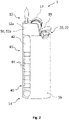
- Figs. 1 and 2 show two different embodiments of the presently disclosed flame producing assembly 1.
- Fig. 1 depicts a schematic illustration of the flame producing assembly 1 having a piezoelectric nanogenerator 52b
- Fig. 2 depicts a schematic illustration of the flame producing assembly 1 having a thermoelectric nanogenerator 52b.
- Fig. 3 shows a schematic diagram of the flame producing assembly 1 mainly including elements which are not visible in the illustrations of Figs. 1 and 2 .
- Figs. 1 and 2 mainly differ with regard to the type of nanogenerator used. Although if some features of the flame producing assembly may only be described with respect to one of the figures, it should be understood that these explanations may in part or fully be applicable to the respective other embodiment.
- the flame producing assembly 1 comprises a main body 10 which has a proximal end 12 and a distal end 14, and an outer surface 16.
- the main body 10 is made of an opaque material. It is to be understood, the main body 10 may alternatively be made of a translucent material.
- the flame producing assembly 1 is configured to produce a flame at the proximal end 12 (see, for instance Fig. 2 ).
- the flame producing assembly 1 comprises a spark wheel 17 and gas release actuator 18 to produce the flame.
- the flame producing assembly 1 comprises a wind guard 12a which is arranged at the proximal end 12 and configured to protect the flame from outer influences, e.g. dirt or wind.
- the wind guard 12a is usually provided in proximity to a fuel release assembly to prevent the rapid extinguishment of the flame by strong wind incident on the lighter.
- the wind guard 12a may be formed of a metal material.
- the flame producing assembly 1 comprises all other elements which are typical for flame producing assemblies 1 and known to those skilled in the art, inter alia a fuel tank, a fuel valve, however, these standard elements are not relevant to the present disclosure and therefore, are not described in detail.
- neither the wind guard 12a is essential to the invention, nor the spark wheel 17 or the gas release actuator 18, as various other techniques of igniting a flame of a flame producing assembly are known to those skilled in the art.
- the flame producing assembly 1 depicted in the figures is configured as a cigarette lighter, in alternative embodiments, the flame producing assembly 1 may be configured as one of a lighter, a butane gas cylinder (for example, as used in a camping stove or Barbeque), a gas-powered soldering iron, or a utility blowtorch for paint stripping.
- a lighter for example, as used in a camping stove or Barbeque
- a gas-powered soldering iron for example, as used in a camping stove or Barbeque
- a utility blowtorch for paint stripping.
- the flame producing assembly 1 comprises a flame signal trigger 20, counting electronics 30, a flame indicator 40, and a power supply 50.
- the flame signal trigger 20 is configured to generate an electrical signal when a flame is currently produced by the flame producing assembly 1. This electrical signal can be processed by the counting electronics 30 which is configured to then determine a number of flames, by for instance adding one count to a memory, or to determine a use time of flames produced by the flame producing assembly 1.
- the flame indicator 40 is configured to output visual feedback indicative of a number of flames and/or use time of flames produced or producible by the flame producing assembly 1.
- the power supply 50 comprises a nanogenerator 52 which is configured to supply the flame producing assembly 1 with power by converting thermal or mechanical energy into electrical energy during use of the flame producing assembly 1.
- a nanogenerator 52 can be understood as a technology that converts mechanical or thermal energy as produced by small-scale physical change into electricity. According to the present disclosure, the nanogenerator 52 can be thermoelectric nanogenerator 52a or a piezoelectric nanogenerator 52b.
- the nanogenerator 52 is a piezoelectric nanogenerator 52b (also referred to as PE nanogenerator) which is arranged on the outer surface 16 of the main body 10. More specifically, the nanogenerator 52b comprises piezoelectric material (also referred to as PE material) which is coated on the outer surface 16 of the main body 10.
- the PE material may comprise, for instance, cellulose microfiber or flexible liquid metal-tin sulfide.
- the PE material may be configured to generate a voltage of, for instance 50mV to 120mV with a power output of several ⁇ W.
- a PE nanogenerator is an energy harvesting device capable of converting external kinetic energy into electrical energy via action by a nano-structured piezoelectric material.
- the flame producing assembly 1 a film-like PE material is covering at least a portion of the main body 10.
- the action of holding the flame producing assembly 1 will induce forces on said film. These forces will physically apply pressure on the film which will cause it to shift internally.
- the crystal structure is under mechanical stress, e.g. squeezed (see, detailed section of Fig. 1 ), causing a transient flow of electrons driven by a piezoelectric potential.
- the piezoelectric nanogenerator 52b is configured to convert mechanical excess energy exerted by a user on the main body 10 during use of the flame producing assembly 1 into electrical energy. For instance, as a user is holding the flame producing assembly 1 (e.g.
- the user could apply more force within their grip than the amount required for only holding the flame producing assembly 1.
- the piezoelectric nanogenerator 52b may, for instance, be attached to the main body 10 mechanically, for instance via adhesives.
- the piezoelectric material may be arranged on an outer surface 16 of the main body 10, where the user holds or touches the main body 10.
- the piezoelectric material may be arranged at finger/palm holding positions of the main body 10.
- An electrical connection may be provided to the counting electronics 30, the flame indicator 40 and/or the flame signal trigger 20, if necessary.
- the structure of the PE nanogenerator 52b may for instance be designed as a sandwich of materials comprising a top film, a middle piezo-crystal structure in the middle, and a bottom film. Further information regarding piezoelectric nanogenerators is described, for instance, by S. Chandrasekaran, C. Bowen, J. Roscow et al.: “Micro-scale to nano-scale generators for energy harvesting: Self powered piezoelectric, triboelectric and hybrid devices", Physics Reports (2019) (https://doi.org/10.1016/j.physrep.2018.11.001. ), by Khan, H., Mahmood, N., Zavabeti, A.
- Nanogenerator can be a TEG or a piezolectric coating.
- TEG converts flame's thermal energy to electricity.
- Piezoelectric converts user's finger/palm mechanical pressure on the body of the lighter to electrical energy even when lighter is not in use and user just holds it.
- the nanogenerator 52 is a thermoelectric nanogenerator 52a (also referred to as TE nanogenerator or TEG) which is arranged at the proximal end 12 of the main body 10.
- the thermoelectric nanogenerator 52a comprises thermoelectric generating material (also referred to as TEG material) which is coated to the wind guard 12a.
- the thermoelectric generating material is coated to an inner surface of the wind guard 12a.
- the TEG material may comprise a doped iron thin film and function based on Nernst effect.
- the thermoelectric nanogenerator 52a is configured to convert excess heat energy of a flame produced during operation of the flame producing assembly 1 into electrical energy.
- An electrical connection may be provided to the counting electronics 30, the flame indicator 40 and/or the flame signal trigger 20, if necessary.
- TEG material may comprise 75 percent iron and 25 percent aluminum (Fe3Al) or gallium (Fe3Ga).
- the TEG material may be coated to at least to a portion of the wind guard 12a.
- the wind guard 12a may be fully coated, at least on an inner surface with the TEG material.
- the thermoelectric generating material may be coated additionally or alternatively to an outer surface of the wind guard 12a.
- the nanogenerator 52 may comprise both, a PE nanogenerator 52b and a TEG 52a as mentioned above. They may both be utilized for energy harvesting.
- the TEG 52a may be configured to serve as a flame signal trigger 20, for instance for detecting when there is a flame and how long it has been on, which will be explained in further detail below.
- the power supply 50 may comprise an energy storage 54.
- the energy storage 54 may be in electrical communication with the nanogenerator 52 and with the counting electronics 30, the flame indicator 40 and/or the flame signal trigger 20.
- the energy storage 54 may be a capacitor.
- the energy storage 54 may be a supercapacitor. In a supercapacitor, energy may be stored electrostatically on the surface of the capacitor material without involving chemical reactions. A supercapacitor can be charged quickly, leading to a very high-power density and does not lose its storage capabilities quickly over time.
- the flame signal trigger 20 may comprise a sensor 22 which is arranged in proximity to the gas release actuator 18.
- the sensor 22 may be arranged distally below the gas release actuator 18 and configured as a mechanical switch such that an actuation of the gas release actuator 18, for instance, by pushing the gas release actuator 18 distally down, is detected by the switch.
- the flame signal trigger 20 is operably coupled to the gas release actuator 18.
- the sensor 22 may be configured to generate an electrical signal upon actuation of the gas release actuator 18. Specifically, an electrical signal may be generated for as long as the gas release actuator 18 is actuated, for instance, for as long as the gas release actuator 18 pushed distally.
- the sensor 22 may be a force sensor, an optical sensor, a pressure sensor, or a piezoelectric sensor.
- the flame signal trigger 20 is in electrical communication with the counting electronics 30 to provide the electrical signal to the counting electronics 30.
- the senor 22 may be a magnetic sensor. Additionally or alternatively, the magnetic sensor may be arranged, for instance in proximity to the spark wheel 17 of the flame producing assembly 1. The magnetic sensor may be arranged and configured to generate an electrical signal upon rotation of the spark wheel 17. Thereby the rotation of the spark wheel may be used as an indicator of a ignition process.
- the flame signal trigger 20 be formed by a thermoelectric nanogenerator 52a which is configured as the thermoelectric nanogenerator 52a mentioned above with respect to Fig. 2 .
- the thermoelectric nanogenerator 52a of Fig. 2 may serve as both the flame signal trigger 20 and the power supply 50.
- thermoelectric nanogenerator 52a of Fig. 2 may serve as the flame signal trigger 20 and the piezoelectric nanogenerator 52b may serve as the power supply 50.
- the thermoelectric nanogenerator 52a is configured to detect an ignition of a flame produced by the flame producing assembly 1.
- thermoelectric nanogenerator 52a is configured to convert excess heat energy of a flame produced during operation of the flame producing assembly 1 into electrical energy.
- the thermoelectric nanogenerator 52a is in electrical communication with the counting electronics 30 which receives the electrical signal from the thermoelectric nanogenerator 52a.
- the counting electronics 30 is configured to determine an ignition of a flame produced by the flame producing assembly 1, when the electrical energy received from the thermoelectric nanogenerator 52a exceeds a predetermined threshold.
- the predetermined threshold may be set at a minimum level of electrical energy which is present when a flame is ignited.
- the predetermined threshold may be configured as a direct function of the generating capacity of the TEG 52a. Based on the type, configuration and materials used for the TEG 52a, a different voltage will be generated for the same temperature. It is clear however that when a flame is present the TEG 52a will produce an impulse voltage as it will have the greatest temperature difference when the flame is lit.
- the threshold voltage can be within about 30% to 70% of the maximum output voltage of the specific TEG 52a. Specifically, the threshold voltage may be about 55% or more of the maximum output voltage of the specific TEG 52a
- the counting electronics 30 is in electrical communication with the power supply 50, with the flame signal trigger 20and with the flame indicator 40 and comprises a processor unit 32.
- the processor unit 32 is configured to receive and process electrical signals generated by the flame signal trigger 20.
- the processor unit 32 is configured to count the number of flames produced by the flame producing assembly 1 based on the received electrical signals. For instance an electrical signal may represent one count of a flame. If further electrical signals are received, the processor unit 32 may for each received signal add one count the previously counted number. Additionally or alternatively, the processor unit 32 may be configured to count the use time of flames produced by the flame producing assembly 1 based on the received electrical signals. For instance, the processor unit 32 may count the time during an electrical signal is received.
- the flame time may be calculated based on the time of electrical signals (e.g. signals received above the predetermined threshold in the case of TEG trigger) being received from the flame signal trigger by the processor unit. If further electrical signals are received, the counted time may be added to the previously counted time. In other words the processor unit 32 counts the number/use time already produced with the flame producing assembly 1 since the initial use. In order to add the count of flames and/or the counted time to the previous values, the counting electronics 30 comprises a memory 34 for storing the number of flames and/or the use time of flames calculated by the processor unit 32.
- the memory 34 may be flash memory. Specifically, the memory 34 may be configured as an ultra-low power flash memory.
- the memory 34 may be a NOR flash memory, see, for instance, Qing Dong et al.: "A 1Mb embedded NOR flash memory with 39 ⁇ W program power for mm-scale high-temperature sensor nodes", February 2017, Conference: 2017 IEEE International Solid- State Circuits Conference - (ISSCC) (DOI:10.1109/ISSCC.2017.7870329 ).
- the memory 34 may be configured to consume less than 50 ⁇ W for a complete cycle of read and write. In some aspects, the memory may be configured to consume between 10 ⁇ W and 500 ⁇ W for a complete cycle of read and write, specifically between 25 ⁇ W to 250 ⁇ W.
- the processor unit 32 stores on the memory 34 the accumulated number of flames and/or the remaining number of flames, i.e. maximum number of flames minus the accumulated number of occurred flames. If the use time of flames is obtained, the processor unit 32 may alternatively or additionally store on the memory 34 the accumulated flame use time and/or the remaining flame use time, i.e. maximum time for how long a flame can be produced with the maximum capacity of the flame producing assembly 1 minus the accumulated time already used for flame production.
- the processor unit 32 may be configured to calculate the number of flames producible by the flame producing assembly 1 based on the received electrical signals. Alternatively or additionally, the processor unit 32 may be configured to calculate the use time of flames producible by the flame producing assembly 1 based on the received electrical signals.
- the memory 34 may comprise a predetermined storage entry of maximum number of flames producible with the fuel capacity of the flame producing assembly 1. In case of the use time of flames, the memory 34 may comprise a predetermined storage entry of maximum use time of flame producible with the fuel capacity of the flame producing assembly 1.
- the processor unit 32 may be configured to calculate the number of flames and/or use time of flame which still can be produced and/or used with the flame producing assembly 1 based on a maximum capacity present at initial use. For instance, the processor unit 32 may be configured to subtract a counted use time from the maximum capacity.
- the processor unit 32 may comprise one or more logic circuits to perform the required mathematical operations.
- the processor unit 32 is configured to drive the flame indicator 40 to output visual feedback to a user indicative of a number of flames and/or use time of flames produced or producible by the flame producing assembly 1. Specifically, the processor unit 32 is configured to generate drive signals which can be used by the flame indicator to display elapsed or remaining flame events and/or elapsed or remaining flame use time.
- the counting electronics 30 may comprise a power regulator 36.
- the power regulator may be in electrical communication with the power supply 50, the flame signal trigger 20 and with the flame indicator 40.
- the power regulator 36 is configured to regulate and distribute power to the flame indicator 40 and within the counting electronics 30. "Within the counting electronics" can be understood as regulating and distributing power to the memory 32 and, the power regulator 36 itself and the processor unit 32.
- the power regulator 36 is also in electrical communication with the memory 34 and the processor unit 32, and, in examples, with any other power requiring device of the flame producing assembly 1, e.g. the flame signal trigger 20 if it is of a type requiring electrical power.
- the counting electronics 30 are embedded to the main body 10. In aspects, the counting electronics 30 may be arranged on or inside the main body 10.
- the flame indicator 40 comprises a display 42.
- the display 42 is arranged on an outer surface 16 of the main body 10.
- the display 42 has a substantially longitudinal shape and extends from a distal end 14 end to a proximal end 12.
- the display 42 covers a portion of the outer surface 16.
- the display 42 may have a different shape, may be arranged at a different portion of the main body 10, and/or may cover more or less of the outer surface 16.
- the display 42 comprises a segmented display strip with a plurality of segments 44 for indicating a number of flames and/or use time of flames produced or producible with the flame producing assembly 1. Each segment 44 may indicate a fractional time interval of use time of flames producible.
- each segment 44 may indicate a multiple of number of flames produced and/or producible and/or a fractional time interval of use time of flames produced.
- the display 42 may comprise a segmented electronic-ink display strip.
- the flame indicator 40 comprises a protective clear layer 46.
- the protective clear 46 layer is arranged on the display 42.
- the protective clear layer 46 is configured to protect the display 42 from wear and degradation through use.
- the display 42 may be an electronic-ink display or an electrophoretic bistable display.
- the display 42 may be a low power TFT or low power LED display.
- the display may be a zenithal bistable display, a bistable liquid crystal display or an electrochromic display.
- an electrophoretic bistable display 42 comprises micrometer sized titanium dioxide particles which are, for instance filled with charged pigments (e.g. black and white pigments positively and negatively charged, respectively).
- the titanium particles may be treated to have electrically charging properties.
- the titanium dioxide particles may be dispersed in a hydrocarbon oil and placed between two conductive plates. One plate may be clear, while the other may be opaque. When a voltage is applied between the two, the particles move to the plate that they are attracted to.
- the particles are located at the front side of the display 42, i.e. the clear plate, it appears white, and black when they are located at the rear side of the display, i.e. the opaque plate.
- the display 42 has a thickness between 0.2mm to 2.0mm. Specifically, the display 42 may have a thickness between 0.5mm to 1.5mm. In particular examples, the display 42 may have a thickness between 0.6 mm to 1.2mm. This enables the display 42 to be integrated in small and thin structures, such as a housing of the flame producing assembly 1, specifically its main body 10. Specifically, the display 42 may be flexible. Thereby, the display 42 can be adapted to the contours, e.g. rounded contours of the flame producing assembly 1. In some examples, the display 42 may be configured to display colored contents. In examples, the display 42 may be configured to display only greyscale contents.
- the flame indicator 40 is in electrical communication with the counting electronics 30.
- the counting electronics 30 is configured to provide the flame indicator 40 with an input signal for outputting visual feedback indicative of a number of flames and/or use time of flames produced or producible by the flame producing assembly 1.
- flame producing assembly 1 By the provision of the presently disclosed flame producing assembly 1, an accurate visualisation of the fuel consumed by a flame producing assembly 1, or the fuel remaining, is possible even if the flame producing assembly 1 is opaque. Furthermore, it may be difficult for users to view the amount of fuel remaining even with translucent bodies.
- Use of a flame indicator 40 as discussed herein can improve visibility in a flame producing assembly 1 having translucent and opaque flame producing assembly bodies 10.
- a further effect is that flame producing assemblies 1 (such as cigarette lighters) are not prematurely disposed of by users, thus reducing plastic waste over time. Furthermore, the lighters that are disposed of can be guaranteed to have exhausted their liquid fuel supply, thus improving the effect on the environment.
- the power supply 50 makes use of energy harvesting via the nanogenerator 52 during use of the flame producing assembly 1, the user does not need to separately activate the flame indicator 40 and/or counting electronics 30 and/or flame signal trigger 20, and no external electronics are required.
- a self-powered and autonomous system for indication the remaining or elapsed use of the lighter, specifically lighter fuel, without the requirement of a battery can be provided. Without the need for a battery, also e-waste can be reduced.
- Due to the autonomous system various information can be gathered and provided to a user, for instance, an estimation of the lighter fuel consumed or the lighter fuel remaining and/or and estimation of the number of flames produced or of the number of flames remaining.
- the indication of number of flames/use time to a user reduces the likelihood of a premature lighter disposal. Furthermore, an increased efficiency can be provided by harvesting mechanical and/or thermal energy with the nanogenerator 52.
- Figs. 4 and 5 depict exemplary methods of using the flame producing assemblies according to Figs. 1 and 2 comprising a piezoelectric nanogenerator and a thermoelectric nanogenerator, respectively.
- the user holds his lighter in his hand pushing the plastic body.
- the PE nanogenerator produces electrical energy to refresh e-ink display and store excess energy in a supercapacitor.
- the user presses the gas pusher and lights a flame.
- the pusher sensor senses the flame lighting action, adds one count to the counter and sets start of flame use time counter in the chip.
- the user lets the pusher and the flame is extinct.
- the pusher sensor stops sensing the flame lighting action and sets end of flame use time counter in the chip.
- the indicator strip increases/decreases proportionally the flame count or the flame use time counter.
- the user holds his lighter in his hand and lights a flame.
- the Thermoelectric generator material absorbs part of the flame's heat and generates electrical current to refresh e-ink display and store excess energy in a supercapacitor. Once the TEG current is over the set threshold, one count is added to the counter and start of flame time counter is set in the chip. The user lets the pusher and the flame is extinct.
- the Thermoelectric generator material stops absorbing flame's heat energy and electric current decreases below set threshold setting end time of the flame use time counter in the chip.
- the indicator strip increases/decreases proportionally the flame count or the flame use time counter.
- a method of using a flame producing assembly comprises: Igniting a flame by an actuator and detecting the ignition by a sensor. Adding one count to a flame counter and counting the flame time until the flame extinguishes, specifically until the actuator is released. Updating a display indicating a remaining or counted number of flames and/or flame time.
- Harvesting electrical energy during use of the flame producing assembly by one of: mechanical force exerted on a main body of the flame producing assembly by a user holding the flame producing assembly, wherein the mechanical force is converted into electrical energy by piezoelectric material applied on the main body (10), or thermal energy which is emitted by the flame during operation of the flame producing assembly, wherein the thermal energy is converted into electrical energy by thermoelectrical material applied on a wind guard in proximity of the flame.
Landscapes
- Engineering & Computer Science (AREA)
- Chemical & Material Sciences (AREA)
- Combustion & Propulsion (AREA)
- Mechanical Engineering (AREA)
- General Engineering & Computer Science (AREA)
- Photometry And Measurement Of Optical Pulse Characteristics (AREA)
Abstract
Description
- The present disclosure relates to the field of flame producing assemblies.
- Flame producing assemblies (FPA) such as lighters are typically used for igniting purposes like igniting tobacco, cigars and/or cigarettes have been developed over the past years. Butane lighters, for instance, work by releasing liquid butane, stored in a pressurized chamber, in a narrow stream of gas. A spark, made by striking a flint with steel or by compressing piezoelectric crystal, ignites the gas which burns at about 2000°C (3600°F). Because butane turns liquid quickly when compressed, and just as quickly returns to gas with reduced pressure, it makes butane gas an ideal fuel for use in lighters. Flame producing assemblies comprise a fuel source of pressurized and liquidized butane.
- Typically, the body of a standard cigarette lighter is often compact, durable, and unbreakable in order to maintain the required gas liquification pressures safely. Therefore, in high quality lighters, special grade opaque plastic materials are used that possess the required mechanical properties to provide a safe enclosure for the liquidized butane. The grade of plastic used for the body of the lighter being non-transparent makes it impossible for a user to see, or to estimate, the level of the liquid fuel quantity remaining inside the plastic container. Therefore, a regular lighter user is not able to verify, easily and accurately, if the lighter contains enough fuel to last for a desired period of time. This means that the user of a conventional cigarette lighter cannot observe the amount of fuel remaining inside a conventional cigarette lighter by visual inspection of the cigarette lighter. This leads to conventional cigarette lighters being disposed of before the liquid fuel supply has been fully exhausted.
- The performance of flame producing assemblies such as cigarette lighters can, therefore, be further improved.
- The present disclosure relates to a flame producing assembly according to
claim 1. The dependent claims depict embodiments of the present disclosure. - The flame producing assembly comprises a main body which has a proximal end and a distal end. The flame producing assembly is configured to produce a flame at the proximal end. Additionally, the flame producing assembly comprises a flame signal trigger, counting electronics, a flame indicator, and a power supply. The flame signal trigger is configured to generate an electrical signal when a flame is currently produced by the flame producing assembly. The counting electronics is configured to calculate a number of flames and/or use time of flames produced by the flame producing assembly. The counting electronics may be an electronic counter. The flame indicator is configured to output visual feedback indicative of a number of flames and/or use time of flames produced or producible by the flame producing assembly. The power supply comprises a nanogenerator which is configured to supply the flame producing assembly with power by converting thermal or mechanical energy into electrical energy during use of the flame producing assembly.
- An accurate visualisation of the fuel consumed by a flame producing assembly, or the fuel remaining, is possible even if the flame producing assembly is opaque. Furthermore, it may be difficult for users to view the amount of fuel remaining even with translucent bodies. Use of a flame indicator as discussed herein can improve visibility in a flame producing assembly having translucent and opaque flame producing assembly bodies. This way flame producing assemblies (such as cigarette lighters) are not prematurely disposed of by users, thus reducing plastic waste over time. Furthermore, the lighters that are disposed of can be guaranteed to have exhausted their liquid fuel supply, thus improving the effect on the environment. As the power supply makes use of energy harvesting via the nanogenerator during use of the flame producing assembly, the user does not need to separately activate the flame indicator and/or counting electronics and/or flame signal trigger, and no external electronics are required. Thereby a self-powered and autonomous system for indication the remaining or elapsed use of the lighter, specifically lighter fuel, without the requirement of a battery can be provided. Without the need for a battery, also e-waste can be reduced. Due to the autonomous system various information can be gathered and provided to a user, for instance, an estimation of the lighter fuel consumed or the lighter fuel remaining and/or and estimation of the number of flames produced or of the number of flames remaining. The indication of number of flames/use time to a user reduces the likelihood of a premature lighter disposal. Furthermore, an increased efficiency can be provided by harvesting mechanical and/or thermal energy with the nanogenerator.
- The nanogenerator may comprise a thermoelectric nanogenerator and/or a piezoelectric nanogenerator.
- In aspects, the thermoelectric nanogenerator may be arranged at the proximal end.
- In aspects, the thermoelectric nanogenerator may be arranged very close to the flame.
- In aspects, the thermoelectric nanogenerator may be arranged on a wind guard of the flame producing assembly. In aspects, the thermoelectric nanogenerator may be arranged in an interior of a wind guard of the flame producing assembly. In examples, the thermoelectric nanogenerator may be arranged on an inner surface of the wind guard. Alternatively or additionally, the thermoelectric nanogenerator may be arranged on an outer surface of the wind guard.
- The thermoelectric nanogenerator may comprise thermoelectric generating material. The thermoelectric generating material may be coated to a wind guard of the flame producing assembly. Specifically, the thermoelectric generating material, may be coated to an inner surface of the wind guard. Alternatively or additionally, the thermoelectric generating material, may be coated to an outer surface of the wind guard.
- The thermoelectric nanogenerator may be configured to convert excess heat energy of a flame produced during operation of the flame producing assembly into electrical energy.
- In aspects, the piezoelectric nanogenerator may be arranged on an outer surface of the main body.
- The piezoelectric nanogenerator may comprise piezoelectric material. The piezoelectric material may be arranged on an outer surface of the main body. Specifically, the piezoelectrical material may be coated to an outer surface of the main body.
- The piezoelectric nanogenerator may be configured to convert mechanical excess energy exerted by a user on the main body during use of the flame producing assembly into electrical energy. For instance, as a user is holding the flame producing assembly (e.g. a cigarette lighter), the user could apply more force within their grip that the amount required for only holding the flame producing assembly. In other words, if a user squeezes the flame producing assembly, they can provide the mechanical pressure required for the piezoelectric generator to be activated and supply power.
- The nanogenerator may be in electrical communication with the counting electronics. Thereby, power can be provided to the counting electronics.
- In aspects, the power supply may comprise an energy storage. The energy storage may be in electrical communication with the nanogenerator. Additionally, the energy storage may be in electrical communication with the counting electronics. In aspects, the energy storage may be a capacitor. Specifically, the energy storage may be a supercapacitor.
- The flame indicator may comprise a display. The display may be arranged on an outer surface of the main body. The display may cover at least a portion of the outer surface. In aspects, the display may be of a substantially rectangular or longitudinal shape. The display may extend from a distal end to a proximal end, or vice versa.
- In aspects, the display may be an electronic-ink display or an electrophoretic bistable display. In examples, the display may be a TFT or LED display.
- In aspects, the display may comprise a segmented display strip. The display may comprise at least two segments for indicating a number of flames and/or use time of flames produced or producible with the flame producing assembly. Specifically, the display may comprise a segmented electronic-ink display strip. Each segment may indicate a multiple of number of flames produced and/or producible or a fractional time interval of use time of flames produced and/or producible.
- In aspects, the flame indicator may comprise a protective clear layer. The protective clear layer may be arranged on the display. The protective clear layer may be configured to protect the display from wear and degradation through use.
- In aspects, the flame indicator may be in electrical communication with the counting electronics. The counting electronics may be configured to provide the flame indicator with an input signal for outputting visual feedback indicative of a number of flames and/or use time of flames produced or producible by the flame producing assembly.
- In aspects, the flame signal trigger may comprise a sensor. The flame signal trigger may be configured to detect an ignition of a flame produced by the flame producing assembly.
- In aspects, the sensor may be a magnetic sensor. The magnetic sensor may be arranged in proximity to a spark wheel of the flame producing assembly and may be configured to generate an electrical signal upon rotation of the spark wheel. Thereby the rotation of the spark wheel may be used as an indicator of an ignition process.
- In aspects, the sensor may be arranged in proximity to a gas release actuator of the flame producing assembly. In other words, the flame signal trigger may be operably coupled to the gas release actuator. The sensor may be configured to generate an electrical signal upon actuation of the gas release actuator. Specifically, an electrical signal may be generated for as long as the gas release actuator is actuated, for instance, for as long as the gas release actuator pushed distally. The sensor may be a mechanical switch. The sensor may be arranged distally below the gas release actuator. Specifically, the sensor may be arranged distally below the gas release actuator such that an actuation of the gas release actuator, for instance, by pushing the gas release actuator distally down, is detected by the switch. In some aspects, the sensor may be a force sensor, an optical sensor, a pressure sensor, or a piezoelectric sensor.
- In aspects, the flame signal trigger may be in electrical communication with the counting electronics to provide the electrical signal to the counting electronics.
- In aspects, the flame signal trigger may comprise a thermoelectric nanogenerator configured to detect an ignition of a flame produced by the flame producing assembly. The thermoelectric nanogenerator may be arranged at the proximal end and configured to convert excess heat energy of a flame produced during operation of the flame producing assembly into electrical energy. The thermoelectric nanogenerator may be in electrical communication with the counting electronics. The counting electronics may be configured to determine an ignition of a flame produced by the flame producing assembly, when the electrical energy received from the thermoelectric nanogenerator exceeds a predetermined threshold. In examples, the predetermined threshold may be set at a minimum level of electrical energy which is present when a flame is ignited.
- In aspects, counting electronics may be in electrical communication with the power supply, with the flame signal trigger and with the flame indicator.
- In aspects, the counting electronics may comprise a processor unit. The processor unit may be configured to receive and process electrical signals generated by the flame signal trigger. The processor unit may be configured to count the number flames of produced by the flame producing assembly based on the received electrical signals. Alternatively or additionally, the processor unit may be configured to count the use time of flames produced by the flame producing assembly based on the received electrical signals. Alternatively or additionally, the processor unit may be configured to calculate the number of flames producible by the flame producing assembly based on the received electrical signals. Alternatively or additionally, the processor unit may be configured to calculate the use time of flames producible by the flame producing assembly based on the received electrical signals.
- In aspects, the processor unit may be configured to drive the flame indicator to output visual feedback indicative of a number of flames and/or use time of flames produced or producible by the flame producing assembly. Specifically, the processor unit may be configured to generate drive signals which can be used by the flame indicator to display elapsed or remaining flame events and/or elapsed or remaining flame use time.
- In aspects, the counting electronics may further comprise a memory for storing the number of flames and/or the use time of flames calculated by the processor unit. The memory may be flash memory. Specifically, the memory may be configured as an ultra-low power flash memory. For instance, the memory may be a NOR flash memory. The memory may be configured to consume less than 50µW for a complete cycle of read and write. In some aspects, the memory may be configured to consume between 10µW and 500µW for a complete cycle of read and write, specifically between 25µW to 250µW.
- In aspects, the counting electronics may comprise a power regulator. The power regulator may be in electrical communication with the power supply, the flame signal trigger and with the flame indicator. The power regulator may be configured to regulate and distribute power to the flame indicator and within the counting electronics.
- In aspects, the counting electronics may be arranged on the main body. In some aspects, the counting electronics may be embedded to the main body.
- In aspects, the main body may be made of an opaque material.
- In aspects, the flame producing assembly may be configured as one of a lighter, a butane gas cylinder, a gas-powered soldering iron, or a utility blowtorch for paint stripping. Specifically, the flame producing assembly may be configured as one of a cigarette lighter, a cigar lighter, a domestic gas ring lighter.
- Other characteristics will be apparent from the accompanying drawings, which form a part of this disclosure. The drawings are intended to further explain the present disclosure and to enable a person skilled in the art to practice it. However, the drawings are intended as nonlimiting examples. Common reference numerals on different figures indicate like or similar features.
- FIG. 1
- shows a schematic illustration of the flame producing assembly having a piezoelectric nanogenerator with a detailed section showing the structure of the piezoelectric nanogenerator;
- FIG. 2
- shows a schematic illustration of the flame producing assembly having a thermoelectric nanogenerator;
- FIG. 3
- shows a schematic diagram of the flame producing assembly;
- FIG. 4
- shows exemplary method steps of using the flame producing assembly according to
Fig. 1 ; - FIG. 5
- shows exemplary method steps of using the flame producing assembly according to
Fig. 2 . - According to the present disclosure, the term "flame producing assembly" may refer to a cigarette lighter, cigar lighter, domestic gas ring lighter, butane gas cylinder (for example, as used in a camping stove or Barbeque), a gas-powered soldering iron, or a utility blowtorch for paint stripping, as examples. Flame producing assemblies are commonly handheld devices, for instance small devices for providing a flame for a cigarette, a candle, or the like.
- According to the present disclosure, the term "proximal" refers to the end of a substantially longitudinal body such as a flame producing assembly that, in use, is closer to an element being lit by the flame producing assembly, such as a cigarette. The term "distal" refers to the end of a substantially longitudinal body such as a flame producing assembly that, in use, is further from element being lit by the flame producing assembly than the "proximal" portion. Thus, proximal can be seen as opposing to distal.
- According to the present disclosure, the term "number of flames" can generally be understood as the estimated, specifically counted, number of flame events, e.g. lighting events, which were carried out (consumed or elapsed number of flames) since initially using the flame producing assembly, or the estimated, specifically calculated, number of flame events, e.g. lighting events, which still can be carried out with respect to a maximum number of flames which can be carried out based on the maximum capacity, particularly maximum fuel capacity, of the flame producing assembly (remaining number of flames). The consumed or elapsed number of flames may also be referred to as number of flames produced. The remaining number of flames may also be referred to as number of flames producible.
- According to the present disclosure, the term "use time of flames" can generally be understood as the estimated, specifically counted, time elapsed for producing a flame (consumed or elapsed use time of flame) since initially using the flame producing assembly, or the estimated, specifically calculated, time remaining for producing a flame (remaining use time of flame) with respect to a maximum time for producing a flame based on the maximum capacity, particularly maximum fuel capacity, of the flame producing assembly. The consumed or elapsed use time of flame may also be referred to as number of flames produced. The remaining use time of flame may also be referred to as number of flames producible.
-
Figs. 1 and2 show two different embodiments of the presently disclosedflame producing assembly 1. WhereasFig. 1 depicts a schematic illustration of theflame producing assembly 1 having apiezoelectric nanogenerator 52b,Fig. 2 depicts a schematic illustration of theflame producing assembly 1 having athermoelectric nanogenerator 52b. Although some elements of the flame producing assemblies are not visible inFigs. 1 and2 , the skilled person will understand that these features may also be comprised in the respective flame producing assembly. In this regard,Fig. 3 shows a schematic diagram of theflame producing assembly 1 mainly including elements which are not visible in the illustrations ofFigs. 1 and2 . - As mentioned in the foregoing paragraph, the exemplary embodiments shown in
Figs. 1 and2 mainly differ with regard to the type of nanogenerator used. Although if some features of the flame producing assembly may only be described with respect to one of the figures, it should be understood that these explanations may in part or fully be applicable to the respective other embodiment. - As illustrated in
Fig. 1 , theflame producing assembly 1 comprises amain body 10 which has aproximal end 12 and adistal end 14, and anouter surface 16. Themain body 10 is made of an opaque material. It is to be understood, themain body 10 may alternatively be made of a translucent material. Theflame producing assembly 1 is configured to produce a flame at the proximal end 12 (see, for instanceFig. 2 ). Theflame producing assembly 1 comprises aspark wheel 17 andgas release actuator 18 to produce the flame. Furthermore, theflame producing assembly 1 comprises awind guard 12a which is arranged at theproximal end 12 and configured to protect the flame from outer influences, e.g. dirt or wind. Thewind guard 12a is usually provided in proximity to a fuel release assembly to prevent the rapid extinguishment of the flame by strong wind incident on the lighter. Specifically, thewind guard 12a may be formed of a metal material. It should be understood that theflame producing assembly 1 comprises all other elements which are typical forflame producing assemblies 1 and known to those skilled in the art, inter alia a fuel tank, a fuel valve, however, these standard elements are not relevant to the present disclosure and therefore, are not described in detail. It should be understood that neither thewind guard 12a is essential to the invention, nor thespark wheel 17 or thegas release actuator 18, as various other techniques of igniting a flame of a flame producing assembly are known to those skilled in the art. Although, theflame producing assembly 1 depicted in the figures is configured as a cigarette lighter, in alternative embodiments, theflame producing assembly 1 may be configured as one of a lighter, a butane gas cylinder (for example, as used in a camping stove or Barbeque), a gas-powered soldering iron, or a utility blowtorch for paint stripping. - The
flame producing assembly 1 comprises aflame signal trigger 20, countingelectronics 30, aflame indicator 40, and apower supply 50. Theflame signal trigger 20 is configured to generate an electrical signal when a flame is currently produced by theflame producing assembly 1. This electrical signal can be processed by the countingelectronics 30 which is configured to then determine a number of flames, by for instance adding one count to a memory, or to determine a use time of flames produced by theflame producing assembly 1. Theflame indicator 40 is configured to output visual feedback indicative of a number of flames and/or use time of flames produced or producible by theflame producing assembly 1. - The
power supply 50 comprises ananogenerator 52 which is configured to supply theflame producing assembly 1 with power by converting thermal or mechanical energy into electrical energy during use of theflame producing assembly 1. Ananogenerator 52 can be understood as a technology that converts mechanical or thermal energy as produced by small-scale physical change into electricity. According to the present disclosure, thenanogenerator 52 can bethermoelectric nanogenerator 52a or apiezoelectric nanogenerator 52b. - In the example of
Fig. 1 , thenanogenerator 52 is apiezoelectric nanogenerator 52b (also referred to as PE nanogenerator) which is arranged on theouter surface 16 of themain body 10. More specifically, thenanogenerator 52b comprises piezoelectric material (also referred to as PE material) which is coated on theouter surface 16 of themain body 10. The PE material may comprise, for instance, cellulose microfiber or flexible liquid metal-tin sulfide. The PE material may be configured to generate a voltage of, for instance 50mV to 120mV with a power output of several µW. A PE nanogenerator is an energy harvesting device capable of converting external kinetic energy into electrical energy via action by a nano-structured piezoelectric material. In the case of the flame producing assembly 1 a film-like PE material is covering at least a portion of themain body 10. The action of holding theflame producing assembly 1 will induce forces on said film. These forces will physically apply pressure on the film which will cause it to shift internally. In detail, the crystal structure is under mechanical stress, e.g. squeezed (see, detailed section ofFig. 1 ), causing a transient flow of electrons driven by a piezoelectric potential. Thereby, thepiezoelectric nanogenerator 52b is configured to convert mechanical excess energy exerted by a user on themain body 10 during use of theflame producing assembly 1 into electrical energy. For instance, as a user is holding the flame producing assembly 1 (e.g. a cigarette lighter), the user could apply more force within their grip than the amount required for only holding theflame producing assembly 1. In other words, if a user squeezes theflame producing assembly 1, the user can provide the mechanical pressure required for thepiezoelectric generator 52b to be activated and supply power. Thepiezoelectric nanogenerator 52b may, for instance, be attached to themain body 10 mechanically, for instance via adhesives. In general, the piezoelectric material may be arranged on anouter surface 16 of themain body 10, where the user holds or touches themain body 10. Specifically, the piezoelectric material may be arranged at finger/palm holding positions of themain body 10. An electrical connection may be provided to the countingelectronics 30, theflame indicator 40 and/or theflame signal trigger 20, if necessary. - The structure of the
PE nanogenerator 52b may for instance be designed as a sandwich of materials comprising a top film, a middle piezo-crystal structure in the middle, and a bottom film. Further information regarding piezoelectric nanogenerators is described, for instance, by S. Chandrasekaran, C. Bowen, J. Roscow et al.: "Micro-scale to nano-scale generators for energy harvesting: Self powered piezoelectric, triboelectric and hybrid devices", Physics Reports (2019) (https://doi.org/10.1016/j.physrep.2018.11.001.), by Khan, H., Mahmood, N., Zavabeti, A. et al.: "Liquid metal-based synthesis of high performance monolayer SnS piezoelectric nanogenerators." Nat Commun 11, 3449 (2020). (https://doi.org/10.1038/s41467-020-17296-0), or by Md. Mehebub Alam and Dipankar Mandal, "Native Cellulose Microfiber-Based Hybrid Piezoelectric Generator for Mechanical Energy Harvesting Utility", ACS Applied Materials & Interfaces 2016 8 (3), 1555-1558 DOI: 10.1021/acsami.5b08168, all of which are hereby incorporated by reference. - Nanogenerator can be a TEG or a piezolectric coating. TEG converts flame's thermal energy to electricity. Piezoelectric converts user's finger/palm mechanical pressure on the body of the lighter to electrical energy even when lighter is not in use and user just holds it.
- In the example of
Fig. 2 , thenanogenerator 52 is athermoelectric nanogenerator 52a (also referred to as TE nanogenerator or TEG) which is arranged at theproximal end 12 of themain body 10. Specifically, thethermoelectric nanogenerator 52a comprises thermoelectric generating material (also referred to as TEG material) which is coated to thewind guard 12a. In examples, the thermoelectric generating material is coated to an inner surface of thewind guard 12a. By arranging theTEG 52a on the inside of thewind guard 12a, theTEG 52a is in close proximity to the flame and thus, the exploitation of thermal energy can be increased in comparison to, for instance arranging the TEG on an outer surface of thewind guard 12a or elsewhere on theflame producing assembly 1. The TEG material may comprise a doped iron thin film and function based on Nernst effect. Thereby, thethermoelectric nanogenerator 52a is configured to convert excess heat energy of a flame produced during operation of theflame producing assembly 1 into electrical energy. An electrical connection may be provided to the countingelectronics 30, theflame indicator 40 and/or theflame signal trigger 20, if necessary. In some examples, TEG material may comprise 75 percent iron and 25 percent aluminum (Fe3Al) or gallium (Fe3Ga). Specifically, the TEG material may be coated to at least to a portion of thewind guard 12a. In examples, thewind guard 12a may be fully coated, at least on an inner surface with the TEG material. In examples, the thermoelectric generating material, may be coated additionally or alternatively to an outer surface of thewind guard 12a. - In examples (not depicted in the figures), the
nanogenerator 52 may comprise both, aPE nanogenerator 52b and aTEG 52a as mentioned above. They may both be utilized for energy harvesting. In some examples, theTEG 52a may be configured to serve as aflame signal trigger 20, for instance for detecting when there is a flame and how long it has been on, which will be explained in further detail below. - In some examples (see,
Fig. 3 ), thepower supply 50 may comprise anenergy storage 54. Theenergy storage 54 may be in electrical communication with thenanogenerator 52 and with the countingelectronics 30, theflame indicator 40 and/or theflame signal trigger 20. In aspects, theenergy storage 54 may be a capacitor. Specifically, theenergy storage 54 may be a supercapacitor. In a supercapacitor, energy may be stored electrostatically on the surface of the capacitor material without involving chemical reactions. A supercapacitor can be charged quickly, leading to a very high-power density and does not lose its storage capabilities quickly over time. - In the examples of
Figs. 1 and2 , theflame signal trigger 20 may comprise asensor 22 which is arranged in proximity to thegas release actuator 18. Specifically, thesensor 22 may be arranged distally below thegas release actuator 18 and configured as a mechanical switch such that an actuation of thegas release actuator 18, for instance, by pushing thegas release actuator 18 distally down, is detected by the switch. In other words, theflame signal trigger 20 is operably coupled to thegas release actuator 18. Thesensor 22 may be configured to generate an electrical signal upon actuation of thegas release actuator 18. Specifically, an electrical signal may be generated for as long as thegas release actuator 18 is actuated, for instance, for as long as thegas release actuator 18 pushed distally. In some aspects, thesensor 22 may be a force sensor, an optical sensor, a pressure sensor, or a piezoelectric sensor. In aspects, theflame signal trigger 20 is in electrical communication with the countingelectronics 30 to provide the electrical signal to the countingelectronics 30. - In examples (not depicted in the figures), the
sensor 22 may be a magnetic sensor. Additionally or alternatively, the magnetic sensor may be arranged, for instance in proximity to thespark wheel 17 of theflame producing assembly 1. The magnetic sensor may be arranged and configured to generate an electrical signal upon rotation of thespark wheel 17. Thereby the rotation of the spark wheel may be used as an indicator of a ignition process. - In examples, the
flame signal trigger 20 be formed by athermoelectric nanogenerator 52a which is configured as thethermoelectric nanogenerator 52a mentioned above with respect toFig. 2 . In some examples, thethermoelectric nanogenerator 52a ofFig. 2 may serve as both theflame signal trigger 20 and thepower supply 50. In examples,thermoelectric nanogenerator 52a ofFig. 2 may serve as theflame signal trigger 20 and thepiezoelectric nanogenerator 52b may serve as thepower supply 50. Thethermoelectric nanogenerator 52a is configured to detect an ignition of a flame produced by theflame producing assembly 1. This is possible by arranging thethermoelectric nanogenerator 52a close to a flame as mentioned above, for instance, by arranging thethermoelectric nanogenerator 52a at theproximal end 12. Thethermoelectric nanogenerator 52a is configured to convert excess heat energy of a flame produced during operation of theflame producing assembly 1 into electrical energy. Thethermoelectric nanogenerator 52a is in electrical communication with the countingelectronics 30 which receives the electrical signal from thethermoelectric nanogenerator 52a. The countingelectronics 30 is configured to determine an ignition of a flame produced by theflame producing assembly 1, when the electrical energy received from thethermoelectric nanogenerator 52a exceeds a predetermined threshold. The predetermined threshold may be set at a minimum level of electrical energy which is present when a flame is ignited. For instance, the predetermined threshold may be configured as a direct function of the generating capacity of theTEG 52a. Based on the type, configuration and materials used for theTEG 52a, a different voltage will be generated for the same temperature. It is clear however that when a flame is present theTEG 52a will produce an impulse voltage as it will have the greatest temperature difference when the flame is lit. For instance, the threshold voltage can be within about 30% to 70% of the maximum output voltage of thespecific TEG 52a. Specifically, the threshold voltage may be about 55% or more of the maximum output voltage of thespecific TEG 52a - The counting
electronics 30 is in electrical communication with thepower supply 50, with the flame signal trigger 20and with theflame indicator 40 and comprises aprocessor unit 32. Theprocessor unit 32 is configured to receive and process electrical signals generated by theflame signal trigger 20. Theprocessor unit 32 is configured to count the number of flames produced by theflame producing assembly 1 based on the received electrical signals. For instance an electrical signal may represent one count of a flame. If further electrical signals are received, theprocessor unit 32 may for each received signal add one count the previously counted number. Additionally or alternatively, theprocessor unit 32 may be configured to count the use time of flames produced by theflame producing assembly 1 based on the received electrical signals. For instance, theprocessor unit 32 may count the time during an electrical signal is received. The flame time may be calculated based on the time of electrical signals (e.g. signals received above the predetermined threshold in the case of TEG trigger) being received from the flame signal trigger by the processor unit. If further electrical signals are received, the counted time may be added to the previously counted time. In other words theprocessor unit 32 counts the number/use time already produced with theflame producing assembly 1 since the initial use. In order to add the count of flames and/or the counted time to the previous values, the countingelectronics 30 comprises amemory 34 for storing the number of flames and/or the use time of flames calculated by theprocessor unit 32. Thememory 34 may be flash memory. Specifically, thememory 34 may be configured as an ultra-low power flash memory. For instance, thememory 34 may be a NOR flash memory, see, for instance, Qing Dong et al.: "A 1Mb embedded NOR flash memory with 39µW program power for mm-scale high-temperature sensor nodes", February 2017, Conference: 2017 IEEE International Solid- State Circuits Conference - (ISSCC) (DOI:10.1109/ISSCC.2017.7870329). Thememory 34 may be configured to consume less than 50µW for a complete cycle of read and write. In some aspects, the memory may be configured to consume between 10µW and 500µW for a complete cycle of read and write, specifically between 25µW to 250µW. In other words, theprocessor unit 32 stores on thememory 34 the accumulated number of flames and/or the remaining number of flames, i.e. maximum number of flames minus the accumulated number of occurred flames. If the use time of flames is obtained, theprocessor unit 32 may alternatively or additionally store on thememory 34 the accumulated flame use time and/or the remaining flame use time, i.e. maximum time for how long a flame can be produced with the maximum capacity of theflame producing assembly 1 minus the accumulated time already used for flame production. - The
processor unit 32 may be configured to calculate the number of flames producible by theflame producing assembly 1 based on the received electrical signals. Alternatively or additionally, theprocessor unit 32 may be configured to calculate the use time of flames producible by theflame producing assembly 1 based on the received electrical signals. In this regard, thememory 34 may comprise a predetermined storage entry of maximum number of flames producible with the fuel capacity of theflame producing assembly 1. In case of the use time of flames, thememory 34 may comprise a predetermined storage entry of maximum use time of flame producible with the fuel capacity of theflame producing assembly 1. Theprocessor unit 32 may be configured to calculate the number of flames and/or use time of flame which still can be produced and/or used with theflame producing assembly 1 based on a maximum capacity present at initial use. For instance, theprocessor unit 32 may be configured to subtract a counted use time from the maximum capacity. Theprocessor unit 32 may comprise one or more logic circuits to perform the required mathematical operations. - The
processor unit 32 is configured to drive theflame indicator 40 to output visual feedback to a user indicative of a number of flames and/or use time of flames produced or producible by theflame producing assembly 1. Specifically, theprocessor unit 32 is configured to generate drive signals which can be used by the flame indicator to display elapsed or remaining flame events and/or elapsed or remaining flame use time. - In some aspects, the counting
electronics 30 may comprise apower regulator 36. The power regulator may be in electrical communication with thepower supply 50, theflame signal trigger 20 and with theflame indicator 40. Thepower regulator 36 is configured to regulate and distribute power to theflame indicator 40 and within the countingelectronics 30. "Within the counting electronics" can be understood as regulating and distributing power to thememory 32 and, thepower regulator 36 itself and theprocessor unit 32. The skilled person will understand that thepower regulator 36 is also in electrical communication with thememory 34 and theprocessor unit 32, and, in examples, with any other power requiring device of theflame producing assembly 1, e.g. theflame signal trigger 20 if it is of a type requiring electrical power. - The counting
electronics 30 are embedded to themain body 10. In aspects, the countingelectronics 30 may be arranged on or inside themain body 10. - As illustrated in
Figs. 1 and2 , theflame indicator 40 comprises adisplay 42. Thedisplay 42 is arranged on anouter surface 16 of themain body 10. Thedisplay 42 has a substantially longitudinal shape and extends from adistal end 14 end to aproximal end 12. Thedisplay 42 covers a portion of theouter surface 16. In examples, thedisplay 42 may have a different shape, may be arranged at a different portion of themain body 10, and/or may cover more or less of theouter surface 16. Thedisplay 42 comprises a segmented display strip with a plurality ofsegments 44 for indicating a number of flames and/or use time of flames produced or producible with theflame producing assembly 1. Eachsegment 44 may indicate a fractional time interval of use time of flames producible. In examples, additionally or alternatively, eachsegment 44 may indicate a multiple of number of flames produced and/or producible and/or a fractional time interval of use time of flames produced. Specifically, thedisplay 42 may comprise a segmented electronic-ink display strip. Theflame indicator 40 comprises a protectiveclear layer 46. The protective clear 46 layer is arranged on thedisplay 42. The protectiveclear layer 46 is configured to protect thedisplay 42 from wear and degradation through use. - In aspects, the
display 42 may be an electronic-ink display or an electrophoretic bistable display. In examples, thedisplay 42 may be a TFT (TFT= thin film transistor display) or LED (LED = light emitting diode display) display. Specifically, thedisplay 42 may be a low power TFT or low power LED display. In some examples, the display may be a zenithal bistable display, a bistable liquid crystal display or an electrochromic display. - In some aspects, an electrophoretic
bistable display 42 comprises micrometer sized titanium dioxide particles which are, for instance filled with charged pigments (e.g. black and white pigments positively and negatively charged, respectively). In configurations, the titanium particles may be treated to have electrically charging properties. The titanium dioxide particles may be dispersed in a hydrocarbon oil and placed between two conductive plates. One plate may be clear, while the other may be opaque. When a voltage is applied between the two, the particles move to the plate that they are attracted to. When the particles are located at the front side of thedisplay 42, i.e. the clear plate, it appears white, and black when they are located at the rear side of the display, i.e. the opaque plate. - The
display 42 has a thickness between 0.2mm to 2.0mm. Specifically, thedisplay 42 may have a thickness between 0.5mm to 1.5mm. In particular examples, thedisplay 42 may have a thickness between 0.6 mm to 1.2mm. This enables thedisplay 42 to be integrated in small and thin structures, such as a housing of theflame producing assembly 1, specifically itsmain body 10. Specifically, thedisplay 42 may be flexible. Thereby, thedisplay 42 can be adapted to the contours, e.g. rounded contours of theflame producing assembly 1. In some examples, thedisplay 42 may be configured to display colored contents. In examples, thedisplay 42 may be configured to display only greyscale contents. - The
flame indicator 40 is in electrical communication with the countingelectronics 30. The countingelectronics 30 is configured to provide theflame indicator 40 with an input signal for outputting visual feedback indicative of a number of flames and/or use time of flames produced or producible by theflame producing assembly 1. - By the provision of the presently disclosed
flame producing assembly 1, an accurate visualisation of the fuel consumed by aflame producing assembly 1, or the fuel remaining, is possible even if theflame producing assembly 1 is opaque. Furthermore, it may be difficult for users to view the amount of fuel remaining even with translucent bodies. Use of aflame indicator 40 as discussed herein can improve visibility in aflame producing assembly 1 having translucent and opaque flame producingassembly bodies 10. A further effect is that flame producing assemblies 1 (such as cigarette lighters) are not prematurely disposed of by users, thus reducing plastic waste over time. Furthermore, the lighters that are disposed of can be guaranteed to have exhausted their liquid fuel supply, thus improving the effect on the environment. As thepower supply 50 makes use of energy harvesting via thenanogenerator 52 during use of theflame producing assembly 1, the user does not need to separately activate theflame indicator 40 and/or countingelectronics 30 and/orflame signal trigger 20, and no external electronics are required. Thereby a self-powered and autonomous system for indication the remaining or elapsed use of the lighter, specifically lighter fuel, without the requirement of a battery can be provided. Without the need for a battery, also e-waste can be reduced. Due to the autonomous system various information can be gathered and provided to a user, for instance, an estimation of the lighter fuel consumed or the lighter fuel remaining and/or and estimation of the number of flames produced or of the number of flames remaining. The indication of number of flames/use time to a user reduces the likelihood of a premature lighter disposal. Furthermore, an increased efficiency can be provided by harvesting mechanical and/or thermal energy with thenanogenerator 52. -
Figs. 4 and5 depict exemplary methods of using the flame producing assemblies according toFigs. 1 and2 comprising a piezoelectric nanogenerator and a thermoelectric nanogenerator, respectively. - According to the method of
Fig. 4 , the user holds his lighter in his hand pushing the plastic body. The PE nanogenerator produces electrical energy to refresh e-ink display and store excess energy in a supercapacitor. The user presses the gas pusher and lights a flame. The pusher sensor senses the flame lighting action, adds one count to the counter and sets start of flame use time counter in the chip. The user lets the pusher and the flame is extinct. The pusher sensor stops sensing the flame lighting action and sets end of flame use time counter in the chip. The indicator strip increases/decreases proportionally the flame count or the flame use time counter. - According to the method of
Fig. 5 , the user holds his lighter in his hand and lights a flame. The Thermoelectric generator material absorbs part of the flame's heat and generates electrical current to refresh e-ink display and store excess energy in a supercapacitor. Once the TEG current is over the set threshold, one count is added to the counter and start of flame time counter is set in the chip. The user lets the pusher and the flame is extinct. The Thermoelectric generator material stops absorbing flame's heat energy and electric current decreases below set threshold setting end time of the flame use time counter in the chip. The indicator strip increases/decreases proportionally the flame count or the flame use time counter. - In general, a method of using a flame producing assembly is disclosed which comprises: Igniting a flame by an actuator and detecting the ignition by a sensor. Adding one count to a flame counter and counting the flame time until the flame extinguishes, specifically until the actuator is released. Updating a display indicating a remaining or counted number of flames and/or flame time. Harvesting electrical energy during use of the flame producing assembly by one of: mechanical force exerted on a main body of the flame producing assembly by a user holding the flame producing assembly, wherein the mechanical force is converted into electrical energy by piezoelectric material applied on the main body (10), or thermal energy which is emitted by the flame during operation of the flame producing assembly, wherein the thermal energy is converted into electrical energy by thermoelectrical material applied on a wind guard in proximity of the flame.
- It should be understood that the present disclosure can also be defined in accordance with the following configurations:
- 1. A flame producing assembly (1) comprising:
- a main body (10) having a proximal end (12) and a distal end (14), wherein the flame producing assembly (1) is configured to produce a flame at the proximal end (12),
- a flame signal trigger (20) configured to generate an electrical signal when a flame is currently produced by the flame producing assembly (1),
- counting electronics (30) configured to calculate a number of flames and/or use time of flames produced by the flame producing assembly (1),
- a flame indicator (40) configured to output visual feedback indicative of a number of flames and/or use time of flames produced or producible by the flame producing assembly (1), and
- a power supply (50) comprising a nanogenerator (52) configured to supply the flame producing assembly (1) with power by converting thermal or mechanical energy into electrical energy during use of the flame producing assembly (1).
- 2. The flame producing assembly (1) of
configuration 1, wherein the nanogenerator (52) comprises a thermoelectric nanogenerator (52a). - 3. The flame producing assembly (1) of configuration 2, wherein the thermoelectric nanogenerator (52a) is arranged at the proximal end (12) and configured to convert excess heat energy of a flame produced during operation of the flame producing assembly (1) into electrical energy.
- 4. The flame producing assembly (1) of any one of configurations 2 or 3, wherein the thermoelectric nanogenerator (52a) comprises thermoelectric generating material, which is arranged on a wind guard (12a) of the flame producing assembly (1).
- 5. The flame producing assembly (1) of any one of the preceding configurations, wherein the nanogenerator (52) comprises a piezoelectric nanogenerator (52b).
- 6. The flame producing assembly (1) of configuration 5, wherein the piezoelectric nanogenerator (52b) is arranged on an outer surface (16) of the main body (10) and configured to convert mechanical excess energy exerted by a user on the main body (10) during use of the flame producing assembly (1) into electrical energy.
- 7. The flame producing assembly (1) of any one of configurations 5 or 6, wherein the piezoelectric nanogenerator (52b) comprises piezoelectric material, which is arranged on an outer surface (16) of the main body (10).
- 8. The flame producing assembly (1) of any one of the preceding configurations, wherein the nanogenerator (52) is in electrical communication with the counting electronics (30).
- 9. The flame producing assembly (1) of any one of the preceding configurations, wherein the power supply (50) comprises an energy storage (54) which is in electrical communication with the nanogenerator (52).
- 10. The flame producing assembly (1) of configuration 9, wherein the energy storage (54) is in electrical communication with the counting electronics (30).
- 11. The flame producing assembly (1) of any one of
configurations 9 or 10, wherein the energy storage (54) is a capacitor, specifically a supercapacitor. - 12. The flame producing assembly (1) of any one of the preceding configurations, wherein the flame indicator (40) comprises a display (42) which is arranged on an outer surface (16) of the main body (10).
- 13. The flame producing assembly (1) of
configuration 12, wherein the display (42) is an electronic-ink display or an electrophoretic bistable display. - 14. The flame producing assembly (1) of
configuration 12, wherein the display (42) is a TFT or LED display. - 15. The flame producing assembly (1) of any one of
configurations 12 to 14, wherein the display (42) comprises a segmented display strip with at least two segments (44) for indicating a number of flames and/or use time of flames produced or producible with the flame producing assembly (1). - 16. The flame producing assembly (1) of any one of
configurations 12 to 15, wherein the flame indicator (40) comprises a protective clear layer (46) arranged on the display (42). - 17. The flame producing assembly (1) of any one of the preceding configurations, wherein the flame indicator (40) is in electrical communication with the counting electronics (30) and wherein the counting electronics (30) is configured to provide the flame indicator (40) with an input signal for outputting visual feedback indicative of a number of flames and/or use time of flames produced or producible by the flame producing assembly (1).
- 18. The flame producing assembly (1) of any one of the preceding configurations, wherein the flame signal trigger (20) comprises a sensor (22) configured to detect an ignition of a flame produced by the flame producing assembly (1).
- 19. The flame producing assembly (1) of
configuration 18, wherein the sensor (22) is a magnetic sensor which is arranged in proximity to a spark wheel (17) of the flame producing assembly (1) and which is configured to generate an electrical signal upon rotation of the spark wheel (17). - 20. The flame producing assembly (1) of
configuration 18, wherein the sensor (22) is arranged in proximity to a gas release actuator (18) of the flame producing assembly (1) and configured to generate an electrical signal upon actuation of the gas release actuator (18). - 21. The flame producing assembly (1) of any one of
configuration 18 to 20, wherein the sensor (22) is a mechanical switch arranged distally below the gas release actuator (18). - 22. The flame producing assembly (1) of any one of the preceding configurations, wherein the flame signal trigger (20) is in electrical communication with the counting electronics (30) to provide the electrical signal to the counting electronics (30).
- 23. The flame producing assembly (1) of any one of the preceding configurations, wherein the flame signal trigger (20) comprises a thermoelectric nanogenerator (52a) configured to detect an ignition of a flame produced by the flame producing assembly (1).
- 24. The flame producing assembly (1) of configuration 23, wherein the thermoelectric nanogenerator (52a) is arranged at the proximal end (12) and configured to convert excess heat energy of a flame produced during operation of the flame producing assembly (1) into electrical energy.
- 25. The flame producing assembly (1) of any one of configurations 23 or 24, wherein the thermoelectric nanogenerator (52a) is in electrical communication with the counting electronics (30) and wherein the counting electronics (30) is configured to determine an ignition of a flame produced by the flame producing assembly (1), when the electrical energy received from the thermoelectric nanogenerator (52a) exceeds a predetermined threshold.
- 26. The flame producing assembly (1) of any one of the preceding configurations, wherein the counting electronics (30) is in electrical communication with the power supply (50), with the flame signal trigger (20) and with the flame indicator (40).
- 27. The flame producing assembly (1) of any one of the preceding configurations, wherein the counting electronics (30) comprise a processor unit (32) configured to receive and process electrical signals generated by the flame signal trigger (20).
- 28. The flame producing assembly (1) of configuration 27, wherein the processor unit (32) is configured to count the number of flames and/or the use time of flames produced by the flame producing assembly (1) based on the received electrical signals.
- 29. The flame producing assembly (1) of any one of configurations 27 or 28, wherein the processor unit (32) is configured to calculate the number of flames and/or the use time of flames producible by the flame producing assembly (1) based on the received electrical signals.
- 30. The flame producing assembly (1) of any one of configurations 27 to 29, wherein the processor unit (32) is configured to drive the flame indicator (40) to output visual feedback indicative of a number of flames and/or use time of flames produced or producible by the flame producing assembly (1).
- 31. The flame producing assembly (1) of any one of configurations 28 to 30, wherein the counting electronics (30) further comprises a memory (34) for storing the number of flames and/or the use time of flames calculated by the processor unit (32).
- 32. The flame producing assembly (1) of configuration 31, wherein the memory (34) is flash memory, specifically an ultra-low power flash memory.
- 33. The flame producing assembly (1) of any one of the preceding configurations, wherein the counting electronics (30) comprises a power regulator (36) which is in electrical communication with the power supply (50), the flame signal trigger (20) and with the flame indicator (40), and which is configured to regulate and distribute power to the flame indicator (40) and within the counting electronics (30).
- 34. The flame producing assembly (1) of any one of the preceding configurations, wherein the counting electronics (30) is arranged on or embedded to the main body (10).
- 35. The flame producing assembly (1) of any one of the preceding configurations, wherein the main body (10) is made of an opaque material.
- 36. The flame producing assembly (1) of any one of the preceding configurations, wherein the flame producing assembly (1) is configured as one of a lighter, a butane gas cylinder, a gas-powered soldering iron, or a utility blowtorch for paint stripping.
-
- 1
- Flame producing assembly
- 10
- Main body
- 12
- Proximal end
- 12a
- Wind guard
- 14
- Distal end
- 16
- Outer surface
- 17
- Spark wheel
- 18
- Gas release actuator
- 20
- Flame signal trigger
- 22
- Sensor
- 30
- Counting electronics
- 32
- Processor unit
- 34
- Memory
- 36
- Power regulator
- 40
- Flame indicator
- 42
- Display
- 44
- Display segment
- 46
- Protective layer
- 50
- Power supply
- 52
- nanogenerator
- 52a
- Thermoelectric nanogenerator
- 52b
- Piezoelectric nanogenerator
- 54
- Energy storage
Claims (15)
- A flame producing assembly (1) comprising:- a main body (10) having a proximal end (12) and a distal end (14), wherein the flame producing assembly (1) is configured to produce a flame at the proximal end (12),- a flame signal trigger (20) configured to generate an electrical signal when a flame is currently produced by the flame producing assembly (1),- counting electronics (30) configured to calculate a number of flames and/or use time of flames produced by the flame producing assembly (1),- a flame indicator (40) configured to output visual feedback indicative of a number of flames and/or use time of flames produced or producible by the flame producing assembly (1), and- a power supply (50) comprising a nanogenerator (52) configured to supply the flame producing assembly (1) with power by converting thermal or mechanical energy into electrical energy during use of the flame producing assembly (1).
- The flame producing assembly (1) of claim 1, wherein the nanogenerator (52) comprises a thermoelectric nanogenerator (52a).
- The flame producing assembly (1) of claim 2, wherein the thermoelectric nanogenerator (52a) is arranged at the proximal end (12) and configured to convert excess heat energy of a flame produced during operation of the flame producing assembly (1) into electrical energy.
- The flame producing assembly (1) of any one of the preceding claims, wherein the nanogenerator (52) comprises a piezoelectric nanogenerator (52b).
- The flame producing assembly (1) of claim 4, wherein the piezoelectric nanogenerator (52b) is arranged on an outer surface (16) of the main body (10) and configured to convert mechanical excess energy exerted by a user on the main body (10) during use of the flame producing assembly (1) into electrical energy.
- The flame producing assembly (1) of any one of the preceding claims, wherein the flame indicator (40) comprises a display (42) which is arranged on an outer surface (16) of the main body (10).
- The flame producing assembly (1) of claim 6, wherein the display (42) comprises a segmented display strip with at least two segments (44) for indicating a number of flames and/or use time of flames produced or producible with the flame producing assembly (1).
- The flame producing assembly (1) of any one of the preceding claims, wherein the flame indicator (40) is in electrical communication with the counting electronics (30) and wherein the counting electronics (30) is configured to provide the flame indicator (40) with an input signal for outputting visual feedback indicative of a number of flames and/or use time of flames produced or producible by the flame producing assembly (1).
- The flame producing assembly (1) of any one of the preceding claims, wherein the flame signal trigger (20) comprises a sensor (22) configured to detect an ignition of a flame produced by the flame producing assembly (1).
- The flame producing assembly (1) of any one of the preceding claims, wherein the flame signal trigger (20) comprises a thermoelectric nanogenerator (52a) configured to detect an ignition of a flame produced by the flame producing assembly (1).
- The flame producing assembly (1) of claim 10, wherein the thermoelectric nanogenerator (52a) is in electrical communication with the counting electronics (30) and wherein the counting electronics (30) is configured to determine an ignition of a flame produced by the flame producing assembly (1), when the electrical energy received from the thermoelectric nanogenerator (52a) exceeds a predetermined threshold.
- The flame producing assembly (1) of any one of the preceding claims, wherein the counting electronics (30) comprise a processor unit (32) configured to receive and process electrical signals generated by the flame signal trigger (20).
- The flame producing assembly (1) of claim 12, wherein the processor unit (32) is configured to count the number of flames and/or the use time of flames produced and/or producible by the flame producing assembly (1) based on the received electrical signals.
- The flame producing assembly (1) of any one of claims 12 or 13, wherein the processor unit (32) is configured to drive the flame indicator (40) to output visual feedback indicative of a number of flames and/or use time of flames produced or producible by the flame producing assembly (1).
- The flame producing assembly (1) of any one of claims 13 or 14, wherein the counting electronics (30) further comprises a memory (34) for storing the number of flames and/or the use time of flames calculated by the processor unit (32).
Priority Applications (4)
| Application Number | Priority Date | Filing Date | Title |
|---|---|---|---|
| EP21194035.8A EP4141323B1 (en) | 2021-08-31 | 2021-08-31 | Flame producing assembly |
| CN202280055710.7A CN117881927A (en) | 2021-08-31 | 2022-08-05 | Flame generating components |
| US18/687,666 US20250137640A1 (en) | 2021-08-31 | 2022-08-05 | Flame producing assemblies |
| PCT/EP2022/072156 WO2023030833A1 (en) | 2021-08-31 | 2022-08-05 | Flame producing assemblies |
Applications Claiming Priority (1)
| Application Number | Priority Date | Filing Date | Title |
|---|---|---|---|
| EP21194035.8A EP4141323B1 (en) | 2021-08-31 | 2021-08-31 | Flame producing assembly |
Publications (2)
| Publication Number | Publication Date |
|---|---|
| EP4141323A1 true EP4141323A1 (en) | 2023-03-01 |
| EP4141323B1 EP4141323B1 (en) | 2026-05-13 |
Family
ID=77897437
Family Applications (1)
| Application Number | Title | Priority Date | Filing Date |
|---|---|---|---|
| EP21194035.8A Active EP4141323B1 (en) | 2021-08-31 | 2021-08-31 | Flame producing assembly |
Country Status (4)
| Country | Link |
|---|---|
| US (1) | US20250137640A1 (en) |
| EP (1) | EP4141323B1 (en) |
| CN (1) | CN117881927A (en) |
| WO (1) | WO2023030833A1 (en) |
Citations (3)
| Publication number | Priority date | Publication date | Assignee | Title |
|---|---|---|---|---|
| JPS5671719A (en) * | 1979-11-14 | 1981-06-15 | Mansei Kogyo Kk | Cigarette lighter equipped with indicator |
| US20070188504A1 (en) * | 2006-02-16 | 2007-08-16 | Lewis Daniel L | Random-text display lighter |
| KR101674523B1 (en) * | 2015-03-20 | 2016-11-09 | 주식회사 케이티앤지 | Beam irradiation type lighter |
Family Cites Families (2)
| Publication number | Priority date | Publication date | Assignee | Title |
|---|---|---|---|---|
| US4311448A (en) * | 1980-03-31 | 1982-01-19 | Edward Strauss | Smoking elimination guidance system |
| CN206755233U (en) * | 2017-03-22 | 2017-12-15 | 汪元礼 | A kind of smoking cessation lighter |
-
2021
- 2021-08-31 EP EP21194035.8A patent/EP4141323B1/en active Active
-
2022
- 2022-08-05 WO PCT/EP2022/072156 patent/WO2023030833A1/en not_active Ceased
- 2022-08-05 US US18/687,666 patent/US20250137640A1/en active Pending
- 2022-08-05 CN CN202280055710.7A patent/CN117881927A/en active Pending
Patent Citations (3)
| Publication number | Priority date | Publication date | Assignee | Title |
|---|---|---|---|---|
| JPS5671719A (en) * | 1979-11-14 | 1981-06-15 | Mansei Kogyo Kk | Cigarette lighter equipped with indicator |
| US20070188504A1 (en) * | 2006-02-16 | 2007-08-16 | Lewis Daniel L | Random-text display lighter |
| KR101674523B1 (en) * | 2015-03-20 | 2016-11-09 | 주식회사 케이티앤지 | Beam irradiation type lighter |
Non-Patent Citations (3)
| Title |
|---|
| "Native Cellulose Microfiber-Based Hybrid Piezoelectric Generator for Mechanical Energy Harvesting Utility", ACS APPLIED MATERIALS & INTERFACES, vol. 8, no. 3, 2016, pages 1555 - 1558 |
| KHAN, H.MAHMOOD, N.ZAVABETI, A. ET AL.: "Liquid metal-based synthesis of high performance monolayer SnS piezoelectric nanogenerators", NAT COMMUN, vol. 11, 2020, pages 3449 |
| S. CHANDRASEKARANC. BOWENJ. ROSCOW ET AL.: "Micro-scale to nano-scale generators for energy harvesting: Self powered piezoelectric, triboelectric and hybrid devices", PHYSICS REPORTS (2019, Retrieved from the Internet <URL:https://doi.org/10.1016/j.physrep.2018.11.001> |
Also Published As
| Publication number | Publication date |
|---|---|
| US20250137640A1 (en) | 2025-05-01 |
| EP4141323B1 (en) | 2026-05-13 |
| WO2023030833A1 (en) | 2023-03-09 |
| CN117881927A (en) | 2024-04-12 |
Similar Documents
| Publication | Publication Date | Title |
|---|---|---|
| CN101655246A (en) | Portable biometric lighter | |
| EP4141323B1 (en) | Flame producing assembly | |
| US20160040877A1 (en) | Electronic candle lighter | |
| CN204421064U (en) | A kind of multifunctional high frequency electric-arc lighter | |
| CN101419727A (en) | Timer and counter | |
| CN205102171U (en) | Lighter based on touch display screen control | |
| CN101440965A (en) | Non-waiting ignition device of gas combustion range | |
| CN203116086U (en) | Touch-control electronic cigarette lighter | |
| JP3175946U (en) | Ignition device | |
| US1466779A (en) | Combined cigar lighter and flash light | |
| CN201680166U (en) | Circuit with battery life indication, flashlight and portable electronic device | |
| CN203421723U (en) | Multifunctional cigarette lighter | |
| CN201037929Y (en) | Solar pen type indicator | |
| CN104578200A (en) | Portable external power supply device for liquefied petroleum gas cooker | |
| CN216481095U (en) | An electronic cigarette lighter circuit | |
| CN206478677U (en) | A kind of electronic lighter | |
| CN203797704U (en) | Electric arc electronic lighter | |
| CN204213968U (en) | A kind of electric-arc lighter | |
| CN102768344B (en) | Waterproof and anti-explosion electric quantity display device for lithium ion battery | |
| CN203010672U (en) | Electronic cigarette lighter | |
| CN102374553A (en) | Novel cigarette igniter | |
| CN210832083U (en) | Electric and gas dual-purpose lighter | |
| CN104566452A (en) | Rechargeable lighter | |
| CN210669894U (en) | Igniter circuit | |
| CN203116082U (en) | Novel dual-purpose wind-proof open fire lighter |
Legal Events
| Date | Code | Title | Description |
|---|---|---|---|
| PUAI | Public reference made under article 153(3) epc to a published international application that has entered the european phase |
Free format text: ORIGINAL CODE: 0009012 |
|
| STAA | Information on the status of an ep patent application or granted ep patent |
Free format text: STATUS: THE APPLICATION HAS BEEN PUBLISHED |
|
| AK | Designated contracting states |
Kind code of ref document: A1 Designated state(s): AL AT BE BG CH CY CZ DE DK EE ES FI FR GB GR HR HU IE IS IT LI LT LU LV MC MK MT NL NO PL PT RO RS SE SI SK SM TR |
|
| STAA | Information on the status of an ep patent application or granted ep patent |
Free format text: STATUS: REQUEST FOR EXAMINATION WAS MADE |
|
| 17P | Request for examination filed |
Effective date: 20230830 |
|
| RBV | Designated contracting states (corrected) |
Designated state(s): AL AT BE BG CH CY CZ DE DK EE ES FI FR GB GR HR HU IE IS IT LI LT LU LV MC MK MT NL NO PL PT RO RS SE SI SK SM TR |
|
| STAA | Information on the status of an ep patent application or granted ep patent |
Free format text: STATUS: EXAMINATION IS IN PROGRESS |
|
| 17Q | First examination report despatched |
Effective date: 20250721 |
|
| GRAP | Despatch of communication of intention to grant a patent |
Free format text: ORIGINAL CODE: EPIDOSNIGR1 |
|
| STAA | Information on the status of an ep patent application or granted ep patent |
Free format text: STATUS: GRANT OF PATENT IS INTENDED |
|
| RIC1 | Information provided on ipc code assigned before grant |
Ipc: F23Q 2/32 20060101AFI20251209BHEP Ipc: F23D 14/38 20060101ALI20251209BHEP Ipc: B23K 3/02 20060101ALN20251209BHEP Ipc: B44D 3/16 20060101ALN20251209BHEP |
|
| INTG | Intention to grant announced |
Effective date: 20251219 |
|
| GRAS | Grant fee paid |
Free format text: ORIGINAL CODE: EPIDOSNIGR3 |
|
| GRAA | (expected) grant |
Free format text: ORIGINAL CODE: 0009210 |
|
| STAA | Information on the status of an ep patent application or granted ep patent |
Free format text: STATUS: THE PATENT HAS BEEN GRANTED |
|
| AK | Designated contracting states |
Kind code of ref document: B1 Designated state(s): AL AT BE BG CH CY CZ DE DK EE ES FI FR GB GR HR HU IE IS IT LI LT LU LV MC MK MT NL NO PL PT RO RS SE SI SK SM TR |
|
| REG | Reference to a national code |
Ref country code: CH Ref legal event code: F10 Free format text: ST27 STATUS EVENT CODE: U-0-0-F10-F00 (AS PROVIDED BY THE NATIONAL OFFICE) Effective date: 20260513 Ref country code: GB Ref legal event code: FG4D |
|
| REG | Reference to a national code |
Ref country code: DE Ref legal event code: R096 Ref document number: 602021054220 Country of ref document: DE |
|
| REG | Reference to a national code |
Ref country code: IE Ref legal event code: FG4D |