EP4141221A1 - Immobilisation tool - Google Patents
Immobilisation tool Download PDFInfo
- Publication number
- EP4141221A1 EP4141221A1 EP22186600.7A EP22186600A EP4141221A1 EP 4141221 A1 EP4141221 A1 EP 4141221A1 EP 22186600 A EP22186600 A EP 22186600A EP 4141221 A1 EP4141221 A1 EP 4141221A1
- Authority
- EP
- European Patent Office
- Prior art keywords
- shaft
- tool
- component
- cylindrical body
- protrusions
- Prior art date
- Legal status (The legal status is an assumption and is not a legal conclusion. Google has not performed a legal analysis and makes no representation as to the accuracy of the status listed.)
- Granted
Links
Images





Classifications
-
- F—MECHANICAL ENGINEERING; LIGHTING; HEATING; WEAPONS; BLASTING
- F01—MACHINES OR ENGINES IN GENERAL; ENGINE PLANTS IN GENERAL; STEAM ENGINES
- F01D—NON-POSITIVE DISPLACEMENT MACHINES OR ENGINES, e.g. STEAM TURBINES
- F01D25/00—Component parts, details, or accessories, not provided for in, or of interest apart from, other groups
- F01D25/28—Supporting or mounting arrangements, e.g. for turbine casing
- F01D25/285—Temporary support structures, e.g. for testing, assembling, installing, repairing; Assembly methods using such structures
-
- F—MECHANICAL ENGINEERING; LIGHTING; HEATING; WEAPONS; BLASTING
- F01—MACHINES OR ENGINES IN GENERAL; ENGINE PLANTS IN GENERAL; STEAM ENGINES
- F01D—NON-POSITIVE DISPLACEMENT MACHINES OR ENGINES, e.g. STEAM TURBINES
- F01D5/00—Blades; Blade-carrying members; Heating, heat-insulating, cooling or antivibration means on the blades or the members
- F01D5/02—Blade-carrying members, e.g. rotors
- F01D5/026—Shaft to shaft connections
-
- F—MECHANICAL ENGINEERING; LIGHTING; HEATING; WEAPONS; BLASTING
- F05—INDEXING SCHEMES RELATING TO ENGINES OR PUMPS IN VARIOUS SUBCLASSES OF CLASSES F01-F04
- F05D—INDEXING SCHEME FOR ASPECTS RELATING TO NON-POSITIVE-DISPLACEMENT MACHINES OR ENGINES, GAS-TURBINES OR JET-PROPULSION PLANTS
- F05D2220/00—Application
- F05D2220/30—Application in turbines
- F05D2220/32—Application in turbines in gas turbines
- F05D2220/323—Application in turbines in gas turbines for aircraft propulsion, e.g. jet engines
-
- F—MECHANICAL ENGINEERING; LIGHTING; HEATING; WEAPONS; BLASTING
- F05—INDEXING SCHEMES RELATING TO ENGINES OR PUMPS IN VARIOUS SUBCLASSES OF CLASSES F01-F04
- F05D—INDEXING SCHEME FOR ASPECTS RELATING TO NON-POSITIVE-DISPLACEMENT MACHINES OR ENGINES, GAS-TURBINES OR JET-PROPULSION PLANTS
- F05D2230/00—Manufacture
- F05D2230/70—Disassembly methods
-
- F—MECHANICAL ENGINEERING; LIGHTING; HEATING; WEAPONS; BLASTING
- F05—INDEXING SCHEMES RELATING TO ENGINES OR PUMPS IN VARIOUS SUBCLASSES OF CLASSES F01-F04
- F05D—INDEXING SCHEME FOR ASPECTS RELATING TO NON-POSITIVE-DISPLACEMENT MACHINES OR ENGINES, GAS-TURBINES OR JET-PROPULSION PLANTS
- F05D2240/00—Components
- F05D2240/60—Shafts
-
- F—MECHANICAL ENGINEERING; LIGHTING; HEATING; WEAPONS; BLASTING
- F05—INDEXING SCHEMES RELATING TO ENGINES OR PUMPS IN VARIOUS SUBCLASSES OF CLASSES F01-F04
- F05D—INDEXING SCHEME FOR ASPECTS RELATING TO NON-POSITIVE-DISPLACEMENT MACHINES OR ENGINES, GAS-TURBINES OR JET-PROPULSION PLANTS
- F05D2260/00—Function
- F05D2260/30—Retaining components in desired mutual position
-
- F—MECHANICAL ENGINEERING; LIGHTING; HEATING; WEAPONS; BLASTING
- F05—INDEXING SCHEMES RELATING TO ENGINES OR PUMPS IN VARIOUS SUBCLASSES OF CLASSES F01-F04
- F05D—INDEXING SCHEME FOR ASPECTS RELATING TO NON-POSITIVE-DISPLACEMENT MACHINES OR ENGINES, GAS-TURBINES OR JET-PROPULSION PLANTS
- F05D2260/00—Function
- F05D2260/30—Retaining components in desired mutual position
- F05D2260/36—Retaining components in desired mutual position by a form fit connection, e.g. by interlocking
-
- F—MECHANICAL ENGINEERING; LIGHTING; HEATING; WEAPONS; BLASTING
- F05—INDEXING SCHEMES RELATING TO ENGINES OR PUMPS IN VARIOUS SUBCLASSES OF CLASSES F01-F04
- F05D—INDEXING SCHEME FOR ASPECTS RELATING TO NON-POSITIVE-DISPLACEMENT MACHINES OR ENGINES, GAS-TURBINES OR JET-PROPULSION PLANTS
- F05D2260/00—Function
- F05D2260/30—Retaining components in desired mutual position
- F05D2260/37—Retaining components in desired mutual position by a press fit connection
Definitions
- the present invention relates to a tool for immobilising a first shaft of a gas turbine engine in relation to a second shaft of the gas turbine engine, and an associated method.
- Aircraft engines are designed to provide many years of operation, and as part of that it is necessary to provide them with periodic servicing and occasional repairs. Sometimes it is necessary to strip down the engine and then rebuild it as part of these processes. Stripping and rebuilding an engine is a complex and time-consuming process, especially when accessing components deep within the engine structure. Because many components within the engine are designed to rotate freely, it is often necessary to immobilise parts of the engine before they, or pieces they are attached to, can be removed.
- a tool for immobilising a first shaft of a gas turbine engine in relation to a second shaft of a gas turbine engine as set out in claim 1.
- Optional features are included in the dependent claims.
- Such a tool is advantageous in the servicing of gas turbine engines, as it reduces the number of parts that need to be removed in order to access certain interior components within the engine, saving time and money for the operator.
- the tool may further comprise a backstop on the exterior surface of the cylindrical body to limit longitudinal movement of the tool in one direction with relation to the second shaft.
- the backstop can be useful in providing consistent positioning of the tool in relation to the shafts.
- the backstop may be integral with the exterior protrusions.
- the interior protrusions of the tool may be at the first end of the cylindrical body.
- the exterior protrusions may be at the second end of the cylindrical body. The arrangement of the protrusions can be adjusted dependent upon the configuration of the shafts being immobilised.
- the tool may comprise stainless steel.
- the tool may further comprise a securing device configured to receive a second section of the first shaft and to create an interference fit with the cylindrical body so as to fix the cylindrical body axially with respect to the first and second shaft.
- a securing device may be helpful in providing consistent positioning of the tool in relation to the shafts, and preventing the tool from becoming prematurely uncoupled from either shaft.
- the securing device may be a threaded nut.
- a method for removing a first component from a gas turbine engine comprising removing the fan case, removing the fan disc, fixing the tool of any preceding claim between the first shaft and a second shaft connected to a second component so as to immobilise the first shaft in relation to the second shaft, and therefore the first component with relation to the second component, immobilising the second component, and removing the first component.
- the first shaft can be an intermediate-pressure shaft, and the first component can be an intermediate pressure compressor module.
- the second shaft can be a low-pressure turbine shaft, and the second component can be a low-pressure turbine.
- the present invention may relate to a gas turbine engine.
- a gas turbine engine may comprise an engine core comprising a turbine, a combustor, a compressor, and a core shaft connecting the turbine to the compressor.
- a gas turbine engine may comprise a fan (having fan blades) located upstream of the engine core.
- the gas turbine engine as described and/or claimed herein may have any suitable general architecture.
- the gas turbine engine may have at least two shafts that connect turbines and compressors.
- the turbine connected to the core shaft may be a first turbine
- the compressor connected to the core shaft may be a first compressor
- the core shaft may be a first core shaft.
- the engine core may further comprise a second turbine, a second compressor, and a second core shaft connecting the second turbine to the second compressor.
- the second turbine, second compressor, and second core shaft may be arranged to rotate at a higher rotational speed than the first core shaft.
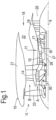
- FIG. 1 illustrates a gas turbine engine 10 having a principal rotational axis 9.
- the engine 10 comprises an air intake 12 and a propulsive fan 23 that generates two airflows: a core airflow A and a bypass airflow B.
- the gas turbine engine 10 comprises a core 11 that receives the core airflow A.
- the engine core 11 comprises, in axial flow series, a low pressure compressor 14, a high-pressure compressor 15, combustion equipment 16, a high-pressure turbine 17, a low pressure turbine 19 and a core exhaust nozzle 20.
- a nacelle 21 surrounds the gas turbine engine 10 and defines a bypass duct 22 and a bypass exhaust nozzle 18.
- the bypass airflow B flows through the bypass duct 22.
- the fan 23 is attached to and driven by the low pressure turbine 19 via a shaft 26 and an epicyclic gearbox 30.
- the core airflow A is accelerated and compressed by the low pressure compressor 14 and directed into the high pressure compressor 15 where further compression takes place.
- the compressed air exhausted from the high pressure compressor 15 is directed into the combustion equipment 16 where it is mixed with fuel and the mixture is combusted.
- the resultant hot combustion products then expand through, and thereby drive, the high pressure and low pressure turbines 17, 19 before being exhausted through the nozzle 20 to provide some propulsive thrust.
- the high pressure turbine 17 drives the high pressure compressor 15 by a suitable interconnecting shaft 27.
- the fan 23 generally provides the majority of the propulsive thrust.
- the epicyclic gearbox 30 is a reduction gearbox.
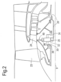
- FIG. 2 An exemplary arrangement for a geared fan gas turbine engine 10 is shown in Figure 2 .
- the low pressure turbine 19 (see Figure 1 ) drives the shaft 26, which is coupled to a sun wheel, or sun gear, 28 of the epicyclic gear arrangement 30.
- a sun wheel, or sun gear, 28 of the epicyclic gear arrangement 30 Radially outwardly of the sun gear 28 and intermeshing therewith is a plurality of planet gears 32 that are coupled together by a planet carrier 34.
- the planet carrier 34 constrains the planet gears 32 to precess around the sun gear 28 in synchronicity whilst enabling each planet gear 32 to rotate about its own axis.
- the planet carrier 34 is coupled via linkages 36 to the fan 23 in order to drive its rotation about the engine axis 9.
- an annulus or ring gear 38 Radially outwardly of the planet gears 32 and intermeshing therewith is an annulus or ring gear 38 that is coupled, via linkages 40, to a stationary supporting structure 24.
- low pressure turbine and “low pressure compressor” as used herein may be taken to mean the lowest pressure turbine stages and lowest pressure compressor stages (i.e. not including the fan 23) respectively and/or the turbine and compressor stages that are connected together by the interconnecting shaft 26 with the lowest rotational speed in the engine (i.e. not including the gearbox output shaft that drives the fan 23).
- the "low pressure turbine” and “low pressure compressor” referred to herein may alternatively be known as the "intermediate pressure turbine” and “intermediate pressure compressor”. Where such alternative nomenclature is used, the fan 23 may be referred to as a first, or lowest pressure, compression stage.
- the epicyclic gearbox 30 is shown by way of example in greater detail in Figure 3 .
- Each of the sun gear 28, planet gears 32 and ring gear 38 comprise teeth about their periphery to intermesh with the other gears. However, for clarity only exemplary portions of the teeth are illustrated in Figure 3 .
- Practical applications of a planetary epicyclic gearbox 30 generally comprise at least three planet gears 32.
- the epicyclic gearbox 30 illustrated by way of example in Figures 2 and 3 is of the planetary type, in that the planet carrier 34 is coupled to an output shaft via linkages 36, with the ring gear 38 fixed.
- the epicyclic gearbox 30 may be a star arrangement, in which the planet carrier 34 is held fixed, with the ring (or annulus) gear 38 allowed to rotate. In such an arrangement the fan 23 is driven by the ring gear 38.
- the gearbox 30 may be a differential gearbox in which the ring gear 38 and the planet carrier 34 are both allowed to rotate.
- any suitable arrangement may be used for locating the gearbox 30 in the engine 10 and/or for connecting the gearbox 30 to the engine 10.
- the connections (such as the linkages 36, 40 in the Figure 2 example) between the gearbox 30 and other parts of the engine 10 (such as the input shaft 26, the output shaft and the fixed structure 24) may have any desired degree of stiffness or flexibility.
- any suitable arrangement of the bearings between rotating and stationary parts of the engine may be used, and the invention is not limited to the exemplary arrangement of Figure 2 .
- the gearbox 30 has a star arrangement (described above)
- the skilled person would readily understand that the arrangement of output and support linkages and bearing locations would typically be different to that shown by way of example in Figure 2 .
- the present invention extends to a gas turbine engine having any arrangement of gearbox styles (for example star or planetary), support structures, input and output shaft arrangement, and bearing locations.
- gearbox styles for example star or planetary
- support structures for example star or planetary
- input and output shaft arrangement for example star or planetary
- bearing locations for example star or planetary
- the gearbox may drive additional and/or alternative components (e.g. the intermediate pressure compressor and/or a booster compressor).
- additional and/or alternative components e.g. the intermediate pressure compressor and/or a booster compressor.
- gas turbine engines to which the present invention may be applied may have alternative configurations.
- such engines may have an alternative number of compressors and/or turbines and/or an alternative number of interconnecting shafts.
- the gas turbine engine shown in Figure 1 has a split flow nozzle 18, 20 meaning that the flow through the bypass duct 22 has its own nozzle 18 that is separate to and radially outside the core exhaust nozzle 20.
- this is not limiting, and any aspect of the present invention may also apply to engines in which the flow through the bypass duct 22 and the flow through the core 11 are mixed, or combined, before (or upstream of) a single nozzle, which may be referred to as a mixed flow nozzle.
- One or both nozzles may have a fixed or variable area.
- the described example relates to a turbofan engine, the invention may apply, for example, to any type of gas turbine engine, such as an open rotor (in which the fan stage is not surrounded by a nacelle) or turboprop engine, for example.
- the gas turbine engine 10 may not comprise a gearbox 30.
- the geometry of the gas turbine engine 10, and components thereof, is defined by a conventional axis system, comprising an axial direction (which is aligned with the rotational axis 9), a radial direction (in the bottom-to-top direction in Figure 1 ), and a circumferential direction (perpendicular to the page in the Figure 1 view).
- the axial, radial and circumferential directions are mutually perpendicular.
- the tool of the present invention is used during the processes of disassembling or reassembling an engine, for example of any of the types previously described.
- the tool can be used in any gas turbine engine system comprising two or more independently rotating shafts that require immobilising for the purposes of building/disassembling the rotating assembly. This could be for example a 2-shaft or 3-shaft engine design.
- the tool of the present invention is designed to immobilise one shaft with respect to another.
- the tool has a generally cylindrical design so that it can be positioned concentrically between a first and second shaft of the gas turbine engine.
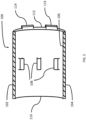
- Figure 4 shows a side-on cut-through view of a tool 100 according to the present invention.
- the tool 100 comprises a generally cylindrical body 102, with an outer surface 104, an inner surface 106, a first end 110 and a second end 112 opposite the first end 110.
- On the inner surface are a number of interior protrusions 108.
- FIG 4 only three interior protrusions 108 are shown on the half of the tool that is visible, but it is to be understood that any number can be present within the tool, including a single interior protrusion, if it is dimensioned appropriately.
- the interior protrusions 108 are aligned axially within the body 102, so as to form a circle of interior protrusions 108 within the tool 100.
- the body 102 of the tool 100 is passed over a section of a first shaft of the engine 10, for example the low-pressure turbine shaft 26.
- the outer surface of the section of the low-pressure turbine shaft 26 comprises a number of slots equal or greater than the number of interior protrusions 108 on the tool, and the low-pressure turbine shaft 26 and/or tool 100 is rotated until each of the interior protrusions 108 is aligned with a slot on the outer surface of the low-pressure turbine shaft 26.
- the interior protrusions 108 of the tool are then slotted into the slots on the outer surface of the low-pressure turbine shaft 26 such that the tool 100 and the low-pressure turbine shaft 26 are interlocked, and fixed relative to one another.
- the tool 100 is brought into contact with a section of a second shaft 132 of the engine 10, for example the interconnecting shaft 27.
- the inner surface of the section of the interconnecting shaft 27 comprises a number of slots equal to or greater than the number of exterior protrusions 114, and the interconnecting shaft 27 and/or tool 100 is rotated until each of the exterior protrusions 114 on the tool is aligned with a slot on the inner surface of the interconnecting shaft 27.
- the exterior protrusions 114 of the tool are then slotted into the slots on the inner surface of the interconnecting shaft 27 such that the tool 100 and the interconnecting shaft 27 are interlocked, and fixed relative to one another.
- the exterior protrusions 114 can be positioned on one of the first 110 or second 112 ends of the body 102, such that they protrude axially along the length of the body.
- the exterior protrusions 114 extend from the second end of the body 102 of the tool 100.
- either the end surface or interior surface of the interconnecting shaft 27 comprises a number of slots equal to or greater than the number of exterior protrusions 114, and the interconnecting shaft 27 and/or tool 100 is rotated until each of the exterior protrusions 114 is aligned with a slot on the end surface or interior surface of the interconnecting shaft 27.
- the exterior protrusions 114 of the tool are then slotted into the slots on the end surface or interior surface of the interconnecting shaft 27 such that the tool 100 and the interconnecting shaft 27 are interlocked, and fixed relative to one another.
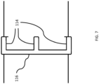
- the outer surface may additionally comprise a backstop 116 such as that shown in Figure 6 .
- the backstop 116 provides a surface against which a surface of the interconnecting shaft 27 can come to rest once the exterior protrusions 114 of the tool 100 have been inserted into the corresponding slots of the interconnecting shaft 27. In this way the backstop provides a datum location to ensure consistent placing of the tool each time it is used.
- the backstop 116 can be integral with the exterior protrusions 114.
- the exterior protrusions 114 are all positioned towards a first end of the body 102 of the tool 100, while the interior protrusions 108 are all positioned towards a second end 112 of the body 102 of the tool 100 opposite to the first end.
- Such a configuration may be advantageous if the ends of the two shafts the tool is to be fitted between are within a distance of each other for which a tool can be readily constructed.
- Figure 9 shows in cross-section an example of how the tool embodiment 100 of Figure 8 can be positioned so as to link two shafts, in this case a first shaft 130 and a second shaft 132, so as to immobilise them with respect to one another.
- the exterior protrusions 114 on the body 102 of the tool 100 engage with the first shaft slots 128 formed on the interior surface of the first shaft 130, whilst the interior protrusions 108 engage with slots 126 formed on the surface of the second shaft 132.
- the exterior protrusions 114 on the body 102 of the tool 100 are on the end surface and extend axially, as shown on the tool of Figure 5 .
- the axial protrusions are accommodated by having the first shaft slots 128 formed on the axially-facing end-surface of the first shaft 130.
- the first shaft slots 128 may be formed in the same position as that shown in Figure 9 , i.e. on the interior surface of the first shaft 130, with an axially-facing opening.
- the slots of the first 130 and second 132 shafts may be positioned at the same axial location (i.e. in the same axial plane) relative to one another, such that the interior 108 and exterior 114 protrusions may also have the same or similar axial location on the body 102 of the tool 100, as shown for example in Figure 4 .
- Figures 9 and 10 also show an optional securing device 134, which can be used to help keep the body 102 of the tool 100 fixed once in place.
- the securing device can be positioned using an interference fit, or could be a threaded nut which is secured to a thread (not shown) on a second section of the exterior surface of the second shaft 132.
- FIG 11 is a schematic illustration of a method 200 for removing an interior component, in this case the intermediate pressure compressor (IPC) module 124, from a gas turbine engine 10 according to the prior art.
- IPC intermediate pressure compressor
- a first step 202 the fan case 118 is removed from the front of the engine 10.
- the fan disc and associated components 120 are also removed from the front of the engine.
- the low-pressure turbine (LPT) module 122 is removed from the rear of the engine. Only once the LPT module has been removed can the intermediate-pressure compressor (IPC) module be removed in step four 208. This is because, before the IPC module can be removed, a further component (not shown) must be removed which otherwise will interfere with the IPC module removal process.
- LPT low-pressure turbine
- the further component is directly linked to the intermediate pressure turbine (IPT) rotor, and is secured inside the IPC module by means of a threaded nut (not shown).
- IPT intermediate pressure turbine
- the IPT rotor In order to remove the nut, the further component, and ultimately the IPC module, the IPT rotor must be immobilised.
- the IPT rotor can only be accessed to be immobilised once the LPT module 122 has been removed. This is usually achieved by fitting an immobilising device (not shown) to the IPT module at the rear of the engine. With the IPT module immobilised, the nut can be removed, followed by the further component, and finally the IPC module.
- Figure 12 is a schematic illustration of a method 300 for removing an interior component such as the IPC from a gas turbine engine 10 according to the present invention.
- the first two steps 302, 304 are the same as those 202, 204 of the known prior art method 200.
- a first step 302 the fan case 118 is removed from the front of the engine 10.
- the fan disc and associated components 120 are also removed from the front of the engine.
- the tool 100 of the present invention is fitted to the first and second shaft, i.e. the IPT and LPT shafts, so that they become fixed in relation to one another.
- the LPT module can be fixed in place using the immobilising device (not shown) previously used to immobilise the IPT module in the method of the prior art. Because the IPT and LPT shafts are now fixed in relation to each other by the tool 100, immobilising the LPT module also immobilises the IPT shaft via the LPT shaft, meaning the nut can be unscrewed, the further component can be removed, and ultimately in step four 308 the IPC module can be removed without the need for removing the LPT module first.
- the disclosed method is therefore less time-consuming than that of the prior art, saving time, resources, and cost for the operator.
Landscapes
- Engineering & Computer Science (AREA)
- Mechanical Engineering (AREA)
- General Engineering & Computer Science (AREA)
- Structures Of Non-Positive Displacement Pumps (AREA)
Abstract
Description
- The present invention relates to a tool for immobilising a first shaft of a gas turbine engine in relation to a second shaft of the gas turbine engine, and an associated method.
- Aircraft engines are designed to provide many years of operation, and as part of that it is necessary to provide them with periodic servicing and occasional repairs. Sometimes it is necessary to strip down the engine and then rebuild it as part of these processes. Stripping and rebuilding an engine is a complex and time-consuming process, especially when accessing components deep within the engine structure. Because many components within the engine are designed to rotate freely, it is often necessary to immobilise parts of the engine before they, or pieces they are attached to, can be removed.
- It would be beneficial to simplify and/or speed up the process for stripping or rebuilding and engine, as saving time and resources required to perform this task also means saving money for the operator.
- In a first aspect there is provided a tool for immobilising a first shaft of a gas turbine engine in relation to a second shaft of a gas turbine engine, as set out in
claim 1. Optional features are included in the dependent claims. Such a tool is advantageous in the servicing of gas turbine engines, as it reduces the number of parts that need to be removed in order to access certain interior components within the engine, saving time and money for the operator. - The tool may further comprise a backstop on the exterior surface of the cylindrical body to limit longitudinal movement of the tool in one direction with relation to the second shaft. The backstop can be useful in providing consistent positioning of the tool in relation to the shafts. The backstop may be integral with the exterior protrusions.
- Optionally, the interior protrusions of the tool may be at the first end of the cylindrical body. Optionally, the exterior protrusions may be at the second end of the cylindrical body. The arrangement of the protrusions can be adjusted dependent upon the configuration of the shafts being immobilised.
- Optionally, the tool may comprise stainless steel.
- The tool may further comprise a securing device configured to receive a second section of the first shaft and to create an interference fit with the cylindrical body so as to fix the cylindrical body axially with respect to the first and second shaft. Such a securing device may be helpful in providing consistent positioning of the tool in relation to the shafts, and preventing the tool from becoming prematurely uncoupled from either shaft. The securing device may be a threaded nut.
- In a second embodiment of the present invention, there is disclosed a method for removing a first component from a gas turbine engine, the first component being fixed to a first shaft, the method comprising removing the fan case, removing the fan disc, fixing the tool of any preceding claim between the first shaft and a second shaft connected to a second component so as to immobilise the first shaft in relation to the second shaft, and therefore the first component with relation to the second component, immobilising the second component, and removing the first component. Such a method is advantageous in the servicing of gas turbine engines, as it reduces the number of parts that need to be removed in order to access certain interior components within the engine, saving time and money for the operator.
- The first shaft can be an intermediate-pressure shaft, and the first component can be an intermediate pressure compressor module. The second shaft can be a low-pressure turbine shaft, and the second component can be a low-pressure turbine.
- As noted elsewhere herein, the present invention may relate to a gas turbine engine. Such a gas turbine engine may comprise an engine core comprising a turbine, a combustor, a compressor, and a core shaft connecting the turbine to the compressor. Such a gas turbine engine may comprise a fan (having fan blades) located upstream of the engine core.
- The gas turbine engine as described and/or claimed herein may have any suitable general architecture. For example, the gas turbine engine may have at least two shafts that connect turbines and compressors. Purely by way of example, the turbine connected to the core shaft may be a first turbine, the compressor connected to the core shaft may be a first compressor, and the core shaft may be a first core shaft. The engine core may further comprise a second turbine, a second compressor, and a second core shaft connecting the second turbine to the second compressor. The second turbine, second compressor, and second core shaft may be arranged to rotate at a higher rotational speed than the first core shaft.
- The skilled person will appreciate that except where mutually exclusive, a feature or parameter described in relation to any one of the above aspects may be applied to any other aspect. Furthermore, except where mutually exclusive, any feature or parameter described herein may be applied to any aspect and/or combined with any other feature or parameter described herein.
- Embodiments will now be described by way of example only, with reference to the Figures, in which:
-
Figure 1 is a sectional side view of a gas turbine engine; -
Figure 2 is a close up sectional side view of an upstream portion of a gas turbine engine; -
Figure 3 is a partially cut-away view of a gearbox for a gas turbine engine; -
Figure 4 is a sectional view of an embodiment of the tool of the present invention; -
Figure 5 is a sectional view of an alternative embodiment of the tool of the present invention; -
Figure 6 is a side-on view of the exterior of an embodiment of the tool of the present invention; -
Figure 7 is a side-on view of the exterior of an alternative embodiment of the tool of the present invention; -
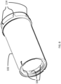
Figure 8 is an isometric view of the exterior of a further embodiment of the tool of the present invention; -
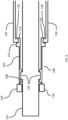
Figure 9 shows a sectional view of an embodiment of the tool in use; -
Figure 10 shows a sectional view of an alternative embodiment of the tool in use; -
Figure 11 illustrates a representation of a method for removing the intermediate pressure compressor (IPC) module from a gas turbine engine as known in the art; and -
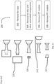
Figure 12 illustrates a representation of a method for removing the intermediate pressure compressor (IPC) module from a gas turbine engine using the tool of the present invention. - Aspects and embodiments of the present invention will now be discussed with reference to the accompanying figures. Further aspects and embodiments will be apparent to those skilled in the art.
-
Figure 1 illustrates agas turbine engine 10 having a principalrotational axis 9. Theengine 10 comprises anair intake 12 and apropulsive fan 23 that generates two airflows: a core airflow A and a bypass airflow B. Thegas turbine engine 10 comprises acore 11 that receives the core airflow A. Theengine core 11 comprises, in axial flow series, alow pressure compressor 14, a high-pressure compressor 15,combustion equipment 16, a high-pressure turbine 17, alow pressure turbine 19 and acore exhaust nozzle 20. Anacelle 21 surrounds thegas turbine engine 10 and defines abypass duct 22 and abypass exhaust nozzle 18. The bypass airflow B flows through thebypass duct 22. Thefan 23 is attached to and driven by thelow pressure turbine 19 via ashaft 26 and anepicyclic gearbox 30. - In use, the core airflow A is accelerated and compressed by the
low pressure compressor 14 and directed into thehigh pressure compressor 15 where further compression takes place. The compressed air exhausted from thehigh pressure compressor 15 is directed into thecombustion equipment 16 where it is mixed with fuel and the mixture is combusted. The resultant hot combustion products then expand through, and thereby drive, the high pressure andlow pressure turbines nozzle 20 to provide some propulsive thrust. Thehigh pressure turbine 17 drives thehigh pressure compressor 15 by a suitable interconnectingshaft 27. Thefan 23 generally provides the majority of the propulsive thrust. Theepicyclic gearbox 30 is a reduction gearbox. - An exemplary arrangement for a geared fan
gas turbine engine 10 is shown inFigure 2 . The low pressure turbine 19 (seeFigure 1 ) drives theshaft 26, which is coupled to a sun wheel, or sun gear, 28 of theepicyclic gear arrangement 30. Radially outwardly of thesun gear 28 and intermeshing therewith is a plurality of planet gears 32 that are coupled together by aplanet carrier 34. Theplanet carrier 34 constrains the planet gears 32 to precess around thesun gear 28 in synchronicity whilst enabling eachplanet gear 32 to rotate about its own axis. Theplanet carrier 34 is coupled vialinkages 36 to thefan 23 in order to drive its rotation about theengine axis 9. Radially outwardly of the planet gears 32 and intermeshing therewith is an annulus orring gear 38 that is coupled, vialinkages 40, to a stationary supportingstructure 24. - Note that the terms "low pressure turbine" and "low pressure compressor" as used herein may be taken to mean the lowest pressure turbine stages and lowest pressure compressor stages (i.e. not including the fan 23) respectively and/or the turbine and compressor stages that are connected together by the interconnecting
shaft 26 with the lowest rotational speed in the engine (i.e. not including the gearbox output shaft that drives the fan 23). In some literature, the "low pressure turbine" and "low pressure compressor" referred to herein may alternatively be known as the "intermediate pressure turbine" and "intermediate pressure compressor". Where such alternative nomenclature is used, thefan 23 may be referred to as a first, or lowest pressure, compression stage. - The
epicyclic gearbox 30 is shown by way of example in greater detail inFigure 3 . Each of thesun gear 28, planet gears 32 andring gear 38 comprise teeth about their periphery to intermesh with the other gears. However, for clarity only exemplary portions of the teeth are illustrated inFigure 3 . There are fourplanet gears 32 illustrated, although it will be apparent to the skilled reader that more or fewer planet gears 32 may be provided within the scope of the claimed invention. Practical applications of a planetaryepicyclic gearbox 30 generally comprise at least three planet gears 32. - The
epicyclic gearbox 30 illustrated by way of example inFigures 2 and3 is of the planetary type, in that theplanet carrier 34 is coupled to an output shaft vialinkages 36, with thering gear 38 fixed. However, any other suitable type ofepicyclic gearbox 30 may be used. By way of further example, theepicyclic gearbox 30 may be a star arrangement, in which theplanet carrier 34 is held fixed, with the ring (or annulus)gear 38 allowed to rotate. In such an arrangement thefan 23 is driven by thering gear 38. By way of further alternative example, thegearbox 30 may be a differential gearbox in which thering gear 38 and theplanet carrier 34 are both allowed to rotate. - It will be appreciated that the arrangement shown in
Figures 2 and3 is by way of example only, and various alternatives are within the scope of the present invention. Purely by way of example, any suitable arrangement may be used for locating thegearbox 30 in theengine 10 and/or for connecting thegearbox 30 to theengine 10. By way of further example, the connections (such as thelinkages Figure 2 example) between thegearbox 30 and other parts of the engine 10 (such as theinput shaft 26, the output shaft and the fixed structure 24) may have any desired degree of stiffness or flexibility. By way of further example, any suitable arrangement of the bearings between rotating and stationary parts of the engine (for example between the input and output shafts from the gearbox and the fixed structures, such as the gearbox casing) may be used, and the invention is not limited to the exemplary arrangement ofFigure 2 . For example, where thegearbox 30 has a star arrangement (described above), the skilled person would readily understand that the arrangement of output and support linkages and bearing locations would typically be different to that shown by way of example inFigure 2 . - Accordingly, the present invention extends to a gas turbine engine having any arrangement of gearbox styles (for example star or planetary), support structures, input and output shaft arrangement, and bearing locations.
- Optionally, the gearbox may drive additional and/or alternative components (e.g. the intermediate pressure compressor and/or a booster compressor).
- Other gas turbine engines to which the present invention may be applied may have alternative configurations. For example, such engines may have an alternative number of compressors and/or turbines and/or an alternative number of interconnecting shafts. By way of further example, the gas turbine engine shown in
Figure 1 has asplit flow nozzle bypass duct 22 has itsown nozzle 18 that is separate to and radially outside thecore exhaust nozzle 20. However, this is not limiting, and any aspect of the present invention may also apply to engines in which the flow through thebypass duct 22 and the flow through the core 11 are mixed, or combined, before (or upstream of) a single nozzle, which may be referred to as a mixed flow nozzle. One or both nozzles (whether mixed or split flow) may have a fixed or variable area. Whilst the described example relates to a turbofan engine, the invention may apply, for example, to any type of gas turbine engine, such as an open rotor (in which the fan stage is not surrounded by a nacelle) or turboprop engine, for example. In some arrangements, thegas turbine engine 10 may not comprise agearbox 30. - The geometry of the
gas turbine engine 10, and components thereof, is defined by a conventional axis system, comprising an axial direction (which is aligned with the rotational axis 9), a radial direction (in the bottom-to-top direction inFigure 1 ), and a circumferential direction (perpendicular to the page in theFigure 1 view). The axial, radial and circumferential directions are mutually perpendicular. - The tool of the present invention is used during the processes of disassembling or reassembling an engine, for example of any of the types previously described. Indeed, the tool can be used in any gas turbine engine system comprising two or more independently rotating shafts that require immobilising for the purposes of building/disassembling the rotating assembly. This could be for example a 2-shaft or 3-shaft engine design.
- The tool of the present invention is designed to immobilise one shaft with respect to another. As such, the tool has a generally cylindrical design so that it can be positioned concentrically between a first and second shaft of the gas turbine engine.
Figure 4 shows a side-on cut-through view of atool 100 according to the present invention. Thetool 100 comprises a generallycylindrical body 102, with anouter surface 104, aninner surface 106, afirst end 110 and asecond end 112 opposite thefirst end 110. On the inner surface are a number ofinterior protrusions 108. InFigure 4 only threeinterior protrusions 108 are shown on the half of the tool that is visible, but it is to be understood that any number can be present within the tool, including a single interior protrusion, if it is dimensioned appropriately. Theinterior protrusions 108 are aligned axially within thebody 102, so as to form a circle ofinterior protrusions 108 within thetool 100. On theouter surface 104 there are a number ofexterior protrusions 114. Only two are shown inFigure 4 , but it is to be understood that any number can be present on the tool, including a single exterior protrusion, if it is dimensioned appropriately. - In use, the
body 102 of thetool 100 is passed over a section of a first shaft of theengine 10, for example the low-pressure turbine shaft 26. The outer surface of the section of the low-pressure turbine shaft 26 comprises a number of slots equal or greater than the number ofinterior protrusions 108 on the tool, and the low-pressure turbine shaft 26 and/ortool 100 is rotated until each of theinterior protrusions 108 is aligned with a slot on the outer surface of the low-pressure turbine shaft 26. Theinterior protrusions 108 of the tool are then slotted into the slots on the outer surface of the low-pressure turbine shaft 26 such that thetool 100 and the low-pressure turbine shaft 26 are interlocked, and fixed relative to one another. - Next, or simultaneously, the
tool 100 is brought into contact with a section of asecond shaft 132 of theengine 10, for example the interconnectingshaft 27. The inner surface of the section of the interconnectingshaft 27 comprises a number of slots equal to or greater than the number ofexterior protrusions 114, and the interconnectingshaft 27 and/ortool 100 is rotated until each of theexterior protrusions 114 on the tool is aligned with a slot on the inner surface of the interconnectingshaft 27. Theexterior protrusions 114 of the tool are then slotted into the slots on the inner surface of the interconnectingshaft 27 such that thetool 100 and the interconnectingshaft 27 are interlocked, and fixed relative to one another. - In an alternative embodiment shown in
Figure 5 , theexterior protrusions 114 can be positioned on one of the first 110 or second 112 ends of thebody 102, such that they protrude axially along the length of the body. In the example shown inFigure 5 , theexterior protrusions 114 extend from the second end of thebody 102 of thetool 100. In this case, either the end surface or interior surface of the interconnectingshaft 27 comprises a number of slots equal to or greater than the number ofexterior protrusions 114, and the interconnectingshaft 27 and/ortool 100 is rotated until each of theexterior protrusions 114 is aligned with a slot on the end surface or interior surface of the interconnectingshaft 27. Theexterior protrusions 114 of the tool are then slotted into the slots on the end surface or interior surface of the interconnectingshaft 27 such that thetool 100 and the interconnectingshaft 27 are interlocked, and fixed relative to one another. - Where the
exterior protrusions 114 are located on theouter surface 104 of thebody 102, the outer surface may additionally comprise abackstop 116 such as that shown inFigure 6 . Thebackstop 116 provides a surface against which a surface of the interconnectingshaft 27 can come to rest once theexterior protrusions 114 of thetool 100 have been inserted into the corresponding slots of the interconnectingshaft 27. In this way the backstop provides a datum location to ensure consistent placing of the tool each time it is used. - In an alternative embodiment shown in
Figure 7 , thebackstop 116 can be integral with theexterior protrusions 114. - In an alternative embodiment shown in
Figure 8 , theexterior protrusions 114 are all positioned towards a first end of thebody 102 of thetool 100, while theinterior protrusions 108 are all positioned towards asecond end 112 of thebody 102 of thetool 100 opposite to the first end. Such a configuration may be advantageous if the ends of the two shafts the tool is to be fitted between are within a distance of each other for which a tool can be readily constructed. -
Figure 9 shows in cross-section an example of how thetool embodiment 100 ofFigure 8 can be positioned so as to link two shafts, in this case afirst shaft 130 and asecond shaft 132, so as to immobilise them with respect to one another. Theexterior protrusions 114 on thebody 102 of thetool 100 engage with thefirst shaft slots 128 formed on the interior surface of thefirst shaft 130, whilst theinterior protrusions 108 engage withslots 126 formed on the surface of thesecond shaft 132. With both theshafts tool 100, immobilisation of one shaft will lead to the immobilisation of both shafts. - It will be readily apparent to the skilled person how the arrangement of protrusions and slots can be altered whilst still achieving the same effect. For example, in
Figure 10 , theexterior protrusions 114 on thebody 102 of thetool 100 are on the end surface and extend axially, as shown on the tool ofFigure 5 . The axial protrusions are accommodated by having thefirst shaft slots 128 formed on the axially-facing end-surface of thefirst shaft 130. Alternatively, thefirst shaft slots 128 may be formed in the same position as that shown inFigure 9 , i.e. on the interior surface of thefirst shaft 130, with an axially-facing opening. In a further alternative, the slots of the first 130 and second 132 shafts may be positioned at the same axial location (i.e. in the same axial plane) relative to one another, such that the interior 108 andexterior 114 protrusions may also have the same or similar axial location on thebody 102 of thetool 100, as shown for example inFigure 4 . -
Figures 9 and10 also show anoptional securing device 134, which can be used to help keep thebody 102 of thetool 100 fixed once in place. The securing device can be positioned using an interference fit, or could be a threaded nut which is secured to a thread (not shown) on a second section of the exterior surface of thesecond shaft 132. -
Figure 11 is a schematic illustration of amethod 200 for removing an interior component, in this case the intermediate pressure compressor (IPC)module 124, from agas turbine engine 10 according to the prior art. In afirst step 202 thefan case 118 is removed from the front of theengine 10. In thesecond step 204 the fan disc and associatedcomponents 120 are also removed from the front of the engine. In thethird step 206 the low-pressure turbine (LPT)module 122 is removed from the rear of the engine. Only once the LPT module has been removed can the intermediate-pressure compressor (IPC) module be removed in step four 208. This is because, before the IPC module can be removed, a further component (not shown) must be removed which otherwise will interfere with the IPC module removal process. The further component is directly linked to the intermediate pressure turbine (IPT) rotor, and is secured inside the IPC module by means of a threaded nut (not shown). In order to remove the nut, the further component, and ultimately the IPC module, the IPT rotor must be immobilised. In this known method of the prior art, the IPT rotor can only be accessed to be immobilised once theLPT module 122 has been removed. This is usually achieved by fitting an immobilising device (not shown) to the IPT module at the rear of the engine. With the IPT module immobilised, the nut can be removed, followed by the further component, and finally the IPC module. -
Figure 12 is a schematic illustration of amethod 300 for removing an interior component such as the IPC from agas turbine engine 10 according to the present invention. The first twosteps prior art method 200. In afirst step 302 thefan case 118 is removed from the front of theengine 10. In thesecond step 304 the fan disc and associatedcomponents 120 are also removed from the front of the engine. In thethird step 306, thetool 100 of the present invention is fitted to the first and second shaft, i.e. the IPT and LPT shafts, so that they become fixed in relation to one another. Once this is done, the LPT module can be fixed in place using the immobilising device (not shown) previously used to immobilise the IPT module in the method of the prior art. Because the IPT and LPT shafts are now fixed in relation to each other by thetool 100, immobilising the LPT module also immobilises the IPT shaft via the LPT shaft, meaning the nut can be unscrewed, the further component can be removed, and ultimately in step four 308 the IPC module can be removed without the need for removing the LPT module first. The disclosed method is therefore less time-consuming than that of the prior art, saving time, resources, and cost for the operator. - It will be understood that the invention is not limited to the embodiments above-described and various modifications and improvements can be made without departing from the concepts described herein, but within the scope of the following claims.
Claims (13)
- A tool (100) for immobilising a first shaft of a gas turbine engine in relation to a second shaft of the gas turbine engine (10), the tool comprising:a cylindrical body (102) having a first end (110) and a second end (112) opposite the first end;the cylindrical body (102) having an inner surface (106) with one or more interior protrusions (108) formed therein for engaging with the first shaft, and an outer surface (104) having one or more exterior protrusions (114) formed thereon for engaging with the second shaft;the tool being configured such that at least part of the tool is insertable within and held fixed relative to a first section of the second shaft via the exterior protrusions (114), and a first section of the first shaft can be inserted within and held fixed relative to the interior of the cylindrical body via the interior protrusions (108).
- The tool of claim 1, further comprising a backstop (116) on the outer surface of the cylindrical body to limit longitudinal movement of the tool in one direction with relation to the second shaft.
- The tool of claim 2, wherein the backstop is integral with the exterior protrusions.
- The tool of any preceding claim, wherein the interior protrusions (108) are at the first end (110) of the cylindrical body.
- The tool of any preceding claim, wherein the exterior protrusions (114) are at the second end (112) of the cylindrical body.
- The tool of any preceding claim, wherein the tool comprises stainless steel.
- The tool of any preceding claim, further comprising a securing device (134), the securing device being configured to receive a second section of the first shaft and to create an interference fit with the cylindrical body so as to fix the cylindrical body axially with respect to the first and second shaft.
- The tool of claim 7, wherein the securing device is a threaded nut.
- A method (300) for removing a first component (124) from a gas turbine engine (10), the first component being fixed to a first shaft (130) of the gas turbine engine, the method comprising:removing the fan case (118);removing the fan disc (120);fixing the tool (100) of any preceding claim between the first shaft and a second shaft (132) connected to a second component (122) so as to immobilise the first shaft in relation to the second shaft, and therefore the first component with relation to the second component;immobilising the second component; andremoving the first component.
- The method of claim 9, wherein the first shaft (130) is an intermediate-pressure turbine shaft.
- The method of claim 9 or 10 wherein the first component (124) is an intermediate pressure compressor module.
- The method of claim 9, 10 or 11, wherein the second shaft (132) is a low-pressure turbine shaft.
- The method of claim 9, 10, 11 or 12, wherein the second component (122) is a low-pressure turbine.
Applications Claiming Priority (1)
| Application Number | Priority Date | Filing Date | Title |
|---|---|---|---|
| GBGB2112031.6A GB202112031D0 (en) | 2021-08-23 | 2021-08-23 | Immobilisation tool |
Publications (2)
| Publication Number | Publication Date |
|---|---|
| EP4141221A1 true EP4141221A1 (en) | 2023-03-01 |
| EP4141221B1 EP4141221B1 (en) | 2024-09-04 |
Family
ID=77913967
Family Applications (1)
| Application Number | Title | Priority Date | Filing Date |
|---|---|---|---|
| EP22186600.7A Active EP4141221B1 (en) | 2021-08-23 | 2022-07-25 | Immobilisation tool |
Country Status (4)
| Country | Link |
|---|---|
| US (1) | US12044139B1 (en) |
| EP (1) | EP4141221B1 (en) |
| CN (1) | CN115709453A (en) |
| GB (1) | GB202112031D0 (en) |
Families Citing this family (1)
| Publication number | Priority date | Publication date | Assignee | Title |
|---|---|---|---|---|
| US12281590B2 (en) * | 2022-06-29 | 2025-04-22 | Ge Infrastructure Technology Llc | System and method for installation or removal of one or more combustion cans |
Citations (3)
| Publication number | Priority date | Publication date | Assignee | Title |
|---|---|---|---|---|
| US6338578B1 (en) * | 1998-09-17 | 2002-01-15 | Societe Nationale d'Etude et de Construction de Moteurs d'Aviation “SNECMA” | Retaining arrangement for a bearing, in particular for a high pressure compressor shaft |
| US7128529B2 (en) * | 2003-07-15 | 2006-10-31 | Snecma Moteurs | Perfected device for securing an engine shaft on a bearing support |
| US20120151735A1 (en) * | 2010-12-20 | 2012-06-21 | Thomas Erik C | Method and Tooling for Partial Disassembly of a Bypass Turbofan Engine |
Family Cites Families (4)
| Publication number | Priority date | Publication date | Assignee | Title |
|---|---|---|---|---|
| US3672708A (en) * | 1970-06-29 | 1972-06-27 | United States Steel Corp | Coupling device |
| US4456425A (en) * | 1980-11-20 | 1984-06-26 | General Electric Company | Modular inlet gearbox for a gas turbine engine |
| US7554771B2 (en) * | 2006-09-11 | 2009-06-30 | Intri-Plex Technologies, Inc. | Tolerance ring for data storage with overlapping tab feature for mass control |
| US10598015B2 (en) | 2017-10-26 | 2020-03-24 | United Technologies Corporation | Anti-rotation assembly |
-
2021
- 2021-08-23 GB GBGB2112031.6A patent/GB202112031D0/en not_active Ceased
-
2022
- 2022-07-25 EP EP22186600.7A patent/EP4141221B1/en active Active
- 2022-08-17 CN CN202210985034.5A patent/CN115709453A/en active Pending
- 2022-08-18 US US17/820,702 patent/US12044139B1/en active Active
Patent Citations (3)
| Publication number | Priority date | Publication date | Assignee | Title |
|---|---|---|---|---|
| US6338578B1 (en) * | 1998-09-17 | 2002-01-15 | Societe Nationale d'Etude et de Construction de Moteurs d'Aviation “SNECMA” | Retaining arrangement for a bearing, in particular for a high pressure compressor shaft |
| US7128529B2 (en) * | 2003-07-15 | 2006-10-31 | Snecma Moteurs | Perfected device for securing an engine shaft on a bearing support |
| US20120151735A1 (en) * | 2010-12-20 | 2012-06-21 | Thomas Erik C | Method and Tooling for Partial Disassembly of a Bypass Turbofan Engine |
Also Published As
| Publication number | Publication date |
|---|---|
| CN115709453A (en) | 2023-02-24 |
| GB202112031D0 (en) | 2021-10-06 |
| US12044139B1 (en) | 2024-07-23 |
| EP4141221B1 (en) | 2024-09-04 |
Similar Documents
| Publication | Publication Date | Title |
|---|---|---|
| US11982238B2 (en) | Fan and low pressure compressor geared to low speed spool of gas turbine engine | |
| US11486269B2 (en) | Gas turbine engine shaft bearing configuration | |
| EP3027877A1 (en) | Gas turbine engine shaft bearing configuration | |
| EP3246517A1 (en) | Fastener openings for stress distribution | |
| US12044139B1 (en) | Immobilisation tool | |
| US20190249720A1 (en) | Driveshaft | |
| US12276228B2 (en) | Planet gear clearances in epicyclic gearboxes | |
| EP3800378B1 (en) | Stiffening member for epicyclical gear system housing assembly | |
| EP3730828B1 (en) | Dynamic sleeve seal fittings | |
| EP3667048B1 (en) | Planet carrier and method of assembling of a planet carrier | |
| CN111594279B (en) | Turbine with alternately spaced rotor blades | |
| EP3477046B1 (en) | Anti-rotation assembly for two coupled shafts, gas turbine engine and corresponding method of assembling a gas turbine engine | |
| GB2588825A (en) | Method and assembly for securing payloads | |
| EP3954885B1 (en) | Deflection limiter for a gas turbine engine | |
| US11795839B2 (en) | Structural assembly for a gas turbine engine | |
| US10563542B2 (en) | Retention hardware | |
| EP3000989B1 (en) | Fan drive gear system | |
| US11994073B2 (en) | Aircraft turbomachine | |
| US11686254B1 (en) | Gearbox assembly | |
| EP3800366B1 (en) | Bearing spring for epicyclical gear system housing assembly | |
| EP3862533A1 (en) | Rotor assembly |
Legal Events
| Date | Code | Title | Description |
|---|---|---|---|
| PUAI | Public reference made under article 153(3) epc to a published international application that has entered the european phase |
Free format text: ORIGINAL CODE: 0009012 |
|
| STAA | Information on the status of an ep patent application or granted ep patent |
Free format text: STATUS: THE APPLICATION HAS BEEN PUBLISHED |
|
| AK | Designated contracting states |
Kind code of ref document: A1 Designated state(s): AL AT BE BG CH CY CZ DE DK EE ES FI FR GB GR HR HU IE IS IT LI LT LU LV MC MK MT NL NO PL PT RO RS SE SI SK SM TR |
|
| STAA | Information on the status of an ep patent application or granted ep patent |
Free format text: STATUS: REQUEST FOR EXAMINATION WAS MADE |
|
| 17P | Request for examination filed |
Effective date: 20230731 |
|
| RBV | Designated contracting states (corrected) |
Designated state(s): AL AT BE BG CH CY CZ DE DK EE ES FI FR GB GR HR HU IE IS IT LI LT LU LV MC MK MT NL NO PL PT RO RS SE SI SK SM TR |
|
| GRAP | Despatch of communication of intention to grant a patent |
Free format text: ORIGINAL CODE: EPIDOSNIGR1 |
|
| STAA | Information on the status of an ep patent application or granted ep patent |
Free format text: STATUS: GRANT OF PATENT IS INTENDED |
|
| GRAS | Grant fee paid |
Free format text: ORIGINAL CODE: EPIDOSNIGR3 |
|
| INTG | Intention to grant announced |
Effective date: 20240625 |
|
| GRAA | (expected) grant |
Free format text: ORIGINAL CODE: 0009210 |
|
| STAA | Information on the status of an ep patent application or granted ep patent |
Free format text: STATUS: THE PATENT HAS BEEN GRANTED |
|
| P01 | Opt-out of the competence of the unified patent court (upc) registered |
Free format text: CASE NUMBER: APP_41215/2024 Effective date: 20240711 |
|
| AK | Designated contracting states |
Kind code of ref document: B1 Designated state(s): AL AT BE BG CH CY CZ DE DK EE ES FI FR GB GR HR HU IE IS IT LI LT LU LV MC MK MT NL NO PL PT RO RS SE SI SK SM TR |
|
| REG | Reference to a national code |
Ref country code: GB Ref legal event code: FG4D |
|
| REG | Reference to a national code |
Ref country code: CH Ref legal event code: EP |
|
| REG | Reference to a national code |
Ref country code: IE Ref legal event code: FG4D |
|
| REG | Reference to a national code |
Ref country code: DE Ref legal event code: R096 Ref document number: 602022005829 Country of ref document: DE |
|
| REG | Reference to a national code |
Ref country code: LT Ref legal event code: MG9D |
|
| REG | Reference to a national code |
Ref country code: NL Ref legal event code: MP Effective date: 20240904 |
|
| PG25 | Lapsed in a contracting state [announced via postgrant information from national office to epo] |
Ref country code: NO Free format text: LAPSE BECAUSE OF FAILURE TO SUBMIT A TRANSLATION OF THE DESCRIPTION OR TO PAY THE FEE WITHIN THE PRESCRIBED TIME-LIMIT Effective date: 20241204 |
|
| PG25 | Lapsed in a contracting state [announced via postgrant information from national office to epo] |
Ref country code: GR Free format text: LAPSE BECAUSE OF FAILURE TO SUBMIT A TRANSLATION OF THE DESCRIPTION OR TO PAY THE FEE WITHIN THE PRESCRIBED TIME-LIMIT Effective date: 20241205 Ref country code: FI Free format text: LAPSE BECAUSE OF FAILURE TO SUBMIT A TRANSLATION OF THE DESCRIPTION OR TO PAY THE FEE WITHIN THE PRESCRIBED TIME-LIMIT Effective date: 20240904 |
|
| PG25 | Lapsed in a contracting state [announced via postgrant information from national office to epo] |
Ref country code: BG Free format text: LAPSE BECAUSE OF FAILURE TO SUBMIT A TRANSLATION OF THE DESCRIPTION OR TO PAY THE FEE WITHIN THE PRESCRIBED TIME-LIMIT Effective date: 20240904 |
|
| PG25 | Lapsed in a contracting state [announced via postgrant information from national office to epo] |
Ref country code: LV Free format text: LAPSE BECAUSE OF FAILURE TO SUBMIT A TRANSLATION OF THE DESCRIPTION OR TO PAY THE FEE WITHIN THE PRESCRIBED TIME-LIMIT Effective date: 20240904 |
|
| PG25 | Lapsed in a contracting state [announced via postgrant information from national office to epo] |
Ref country code: HR Free format text: LAPSE BECAUSE OF FAILURE TO SUBMIT A TRANSLATION OF THE DESCRIPTION OR TO PAY THE FEE WITHIN THE PRESCRIBED TIME-LIMIT Effective date: 20240904 |
|
| PG25 | Lapsed in a contracting state [announced via postgrant information from national office to epo] |
Ref country code: ES Free format text: LAPSE BECAUSE OF FAILURE TO SUBMIT A TRANSLATION OF THE DESCRIPTION OR TO PAY THE FEE WITHIN THE PRESCRIBED TIME-LIMIT Effective date: 20240904 Ref country code: RS Free format text: LAPSE BECAUSE OF FAILURE TO SUBMIT A TRANSLATION OF THE DESCRIPTION OR TO PAY THE FEE WITHIN THE PRESCRIBED TIME-LIMIT Effective date: 20241204 |
|
| PG25 | Lapsed in a contracting state [announced via postgrant information from national office to epo] |
Ref country code: RS Free format text: LAPSE BECAUSE OF FAILURE TO SUBMIT A TRANSLATION OF THE DESCRIPTION OR TO PAY THE FEE WITHIN THE PRESCRIBED TIME-LIMIT Effective date: 20241204 Ref country code: NO Free format text: LAPSE BECAUSE OF FAILURE TO SUBMIT A TRANSLATION OF THE DESCRIPTION OR TO PAY THE FEE WITHIN THE PRESCRIBED TIME-LIMIT Effective date: 20241204 Ref country code: LV Free format text: LAPSE BECAUSE OF FAILURE TO SUBMIT A TRANSLATION OF THE DESCRIPTION OR TO PAY THE FEE WITHIN THE PRESCRIBED TIME-LIMIT Effective date: 20240904 Ref country code: HR Free format text: LAPSE BECAUSE OF FAILURE TO SUBMIT A TRANSLATION OF THE DESCRIPTION OR TO PAY THE FEE WITHIN THE PRESCRIBED TIME-LIMIT Effective date: 20240904 Ref country code: GR Free format text: LAPSE BECAUSE OF FAILURE TO SUBMIT A TRANSLATION OF THE DESCRIPTION OR TO PAY THE FEE WITHIN THE PRESCRIBED TIME-LIMIT Effective date: 20241205 Ref country code: FI Free format text: LAPSE BECAUSE OF FAILURE TO SUBMIT A TRANSLATION OF THE DESCRIPTION OR TO PAY THE FEE WITHIN THE PRESCRIBED TIME-LIMIT Effective date: 20240904 Ref country code: ES Free format text: LAPSE BECAUSE OF FAILURE TO SUBMIT A TRANSLATION OF THE DESCRIPTION OR TO PAY THE FEE WITHIN THE PRESCRIBED TIME-LIMIT Effective date: 20240904 Ref country code: BG Free format text: LAPSE BECAUSE OF FAILURE TO SUBMIT A TRANSLATION OF THE DESCRIPTION OR TO PAY THE FEE WITHIN THE PRESCRIBED TIME-LIMIT Effective date: 20240904 |
|
| REG | Reference to a national code |
Ref country code: AT Ref legal event code: MK05 Ref document number: 1720609 Country of ref document: AT Kind code of ref document: T Effective date: 20240904 |
|
| PG25 | Lapsed in a contracting state [announced via postgrant information from national office to epo] |
Ref country code: NL Free format text: LAPSE BECAUSE OF FAILURE TO SUBMIT A TRANSLATION OF THE DESCRIPTION OR TO PAY THE FEE WITHIN THE PRESCRIBED TIME-LIMIT Effective date: 20240904 |
|
| PG25 | Lapsed in a contracting state [announced via postgrant information from national office to epo] |
Ref country code: IS Free format text: LAPSE BECAUSE OF FAILURE TO SUBMIT A TRANSLATION OF THE DESCRIPTION OR TO PAY THE FEE WITHIN THE PRESCRIBED TIME-LIMIT Effective date: 20250104 Ref country code: PT Free format text: LAPSE BECAUSE OF FAILURE TO SUBMIT A TRANSLATION OF THE DESCRIPTION OR TO PAY THE FEE WITHIN THE PRESCRIBED TIME-LIMIT Effective date: 20250106 |
|
| PG25 | Lapsed in a contracting state [announced via postgrant information from national office to epo] |
Ref country code: RO Free format text: LAPSE BECAUSE OF FAILURE TO SUBMIT A TRANSLATION OF THE DESCRIPTION OR TO PAY THE FEE WITHIN THE PRESCRIBED TIME-LIMIT Effective date: 20240904 Ref country code: SM Free format text: LAPSE BECAUSE OF FAILURE TO SUBMIT A TRANSLATION OF THE DESCRIPTION OR TO PAY THE FEE WITHIN THE PRESCRIBED TIME-LIMIT Effective date: 20240904 |
|
| PG25 | Lapsed in a contracting state [announced via postgrant information from national office to epo] |
Ref country code: EE Free format text: LAPSE BECAUSE OF FAILURE TO SUBMIT A TRANSLATION OF THE DESCRIPTION OR TO PAY THE FEE WITHIN THE PRESCRIBED TIME-LIMIT Effective date: 20240904 Ref country code: AT Free format text: LAPSE BECAUSE OF FAILURE TO SUBMIT A TRANSLATION OF THE DESCRIPTION OR TO PAY THE FEE WITHIN THE PRESCRIBED TIME-LIMIT Effective date: 20240904 |
|
| PG25 | Lapsed in a contracting state [announced via postgrant information from national office to epo] |
Ref country code: PL Free format text: LAPSE BECAUSE OF FAILURE TO SUBMIT A TRANSLATION OF THE DESCRIPTION OR TO PAY THE FEE WITHIN THE PRESCRIBED TIME-LIMIT Effective date: 20240904 Ref country code: CZ Free format text: LAPSE BECAUSE OF FAILURE TO SUBMIT A TRANSLATION OF THE DESCRIPTION OR TO PAY THE FEE WITHIN THE PRESCRIBED TIME-LIMIT Effective date: 20240904 |
|
| PG25 | Lapsed in a contracting state [announced via postgrant information from national office to epo] |
Ref country code: SK Free format text: LAPSE BECAUSE OF FAILURE TO SUBMIT A TRANSLATION OF THE DESCRIPTION OR TO PAY THE FEE WITHIN THE PRESCRIBED TIME-LIMIT Effective date: 20240904 Ref country code: IT Free format text: LAPSE BECAUSE OF FAILURE TO SUBMIT A TRANSLATION OF THE DESCRIPTION OR TO PAY THE FEE WITHIN THE PRESCRIBED TIME-LIMIT Effective date: 20240904 |
|
| REG | Reference to a national code |
Ref country code: DE Ref legal event code: R097 Ref document number: 602022005829 Country of ref document: DE |
|
| PG25 | Lapsed in a contracting state [announced via postgrant information from national office to epo] |
Ref country code: DK Free format text: LAPSE BECAUSE OF FAILURE TO SUBMIT A TRANSLATION OF THE DESCRIPTION OR TO PAY THE FEE WITHIN THE PRESCRIBED TIME-LIMIT Effective date: 20240904 |
|
| PLBE | No opposition filed within time limit |
Free format text: ORIGINAL CODE: 0009261 |
|
| STAA | Information on the status of an ep patent application or granted ep patent |
Free format text: STATUS: NO OPPOSITION FILED WITHIN TIME LIMIT |
|
| 26N | No opposition filed |
Effective date: 20250605 |
|
| PG25 | Lapsed in a contracting state [announced via postgrant information from national office to epo] |
Ref country code: SE Free format text: LAPSE BECAUSE OF FAILURE TO SUBMIT A TRANSLATION OF THE DESCRIPTION OR TO PAY THE FEE WITHIN THE PRESCRIBED TIME-LIMIT Effective date: 20240904 |
|
| PGFP | Annual fee paid to national office [announced via postgrant information from national office to epo] |
Ref country code: DE Payment date: 20250728 Year of fee payment: 4 |
|
| PGFP | Annual fee paid to national office [announced via postgrant information from national office to epo] |
Ref country code: FR Payment date: 20250725 Year of fee payment: 4 |
|
| REG | Reference to a national code |
Ref country code: CH Ref legal event code: H13 Free format text: ST27 STATUS EVENT CODE: U-0-0-H10-H13 (AS PROVIDED BY THE NATIONAL OFFICE) Effective date: 20260224 |
|
| PG25 | Lapsed in a contracting state [announced via postgrant information from national office to epo] |
Ref country code: LU Free format text: LAPSE BECAUSE OF NON-PAYMENT OF DUE FEES Effective date: 20250725 |
|
| REG | Reference to a national code |
Ref country code: BE Ref legal event code: MM Effective date: 20250731 |
|
| PG25 | Lapsed in a contracting state [announced via postgrant information from national office to epo] |
Ref country code: BE Free format text: LAPSE BECAUSE OF NON-PAYMENT OF DUE FEES Effective date: 20250731 |
|
| PG25 | Lapsed in a contracting state [announced via postgrant information from national office to epo] |
Ref country code: CH Free format text: LAPSE BECAUSE OF NON-PAYMENT OF DUE FEES Effective date: 20250731 |