EP4141219A1 - Sealing device and flow machine with the sealing device - Google Patents
Sealing device and flow machine with the sealing device Download PDFInfo
- Publication number
- EP4141219A1 EP4141219A1 EP21192697.7A EP21192697A EP4141219A1 EP 4141219 A1 EP4141219 A1 EP 4141219A1 EP 21192697 A EP21192697 A EP 21192697A EP 4141219 A1 EP4141219 A1 EP 4141219A1
- Authority
- EP
- European Patent Office
- Prior art keywords
- protrusion
- sealing device
- biasing means
- flap seal
- region
- Prior art date
- Legal status (The legal status is an assumption and is not a legal conclusion. Google has not performed a legal analysis and makes no representation as to the accuracy of the status listed.)
- Withdrawn
Links
- 238000007789 sealing Methods 0.000 title claims abstract description 44
Images
Classifications
-
- F—MECHANICAL ENGINEERING; LIGHTING; HEATING; WEAPONS; BLASTING
- F16—ENGINEERING ELEMENTS AND UNITS; GENERAL MEASURES FOR PRODUCING AND MAINTAINING EFFECTIVE FUNCTIONING OF MACHINES OR INSTALLATIONS; THERMAL INSULATION IN GENERAL
- F16J—PISTONS; CYLINDERS; SEALINGS
- F16J15/00—Sealings
- F16J15/02—Sealings between relatively-stationary surfaces
- F16J15/06—Sealings between relatively-stationary surfaces with solid packing compressed between sealing surfaces
- F16J15/08—Sealings between relatively-stationary surfaces with solid packing compressed between sealing surfaces with exclusively metal packing
- F16J15/0887—Sealings between relatively-stationary surfaces with solid packing compressed between sealing surfaces with exclusively metal packing the sealing effect being obtained by elastic deformation of the packing
-
- F—MECHANICAL ENGINEERING; LIGHTING; HEATING; WEAPONS; BLASTING
- F01—MACHINES OR ENGINES IN GENERAL; ENGINE PLANTS IN GENERAL; STEAM ENGINES
- F01D—NON-POSITIVE DISPLACEMENT MACHINES OR ENGINES, e.g. STEAM TURBINES
- F01D11/00—Preventing or minimising internal leakage of working-fluid, e.g. between stages
- F01D11/005—Sealing means between non relatively rotating elements
-
- F—MECHANICAL ENGINEERING; LIGHTING; HEATING; WEAPONS; BLASTING
- F05—INDEXING SCHEMES RELATING TO ENGINES OR PUMPS IN VARIOUS SUBCLASSES OF CLASSES F01-F04
- F05D—INDEXING SCHEME FOR ASPECTS RELATING TO NON-POSITIVE-DISPLACEMENT MACHINES OR ENGINES, GAS-TURBINES OR JET-PROPULSION PLANTS
- F05D2240/00—Components
- F05D2240/55—Seals
- F05D2240/57—Leaf seals
Definitions
- Flap seals are conventionally provided for sealing gaps, in particular in a flow machine.
- the sealing of the gaps in a flow machine reduces a leakage within the flow machine and therefore leads to an increased efficiency of the flow machine.
- Flap seals are conventionally pushed by a spring against the gap for which the spring has to be supported.
- space consuming structures have to be provided. These space consuming structures lead to increased costs and less available space.
- the inventive sealing device for a flow machine comprises a flap seal, a surface, a first protrusion protruding from the surface, a second protrusion protruding from the surface and a biasing means that is supported on the first protrusion and the second protrusion and is adapted to push the flap seal away from the first protrusion and the second protrusion in a direction transversal to the normal of the surface, wherein the biasing means comprises a foot that protrudes from a first region of the biasing means in a direction towards the surface, wherein the first region is arranged immediately neighboured to the foot, wherein the foot contacts the surface and biases the remaining biasing means in a direction away from the first protrusion and the second protrusion.
- the remaining biasing means in particular the first region, is biased in a direction away from the first protrusion and the second protrusion. It is therefore not required to provide a spring at a distance from the surface in which the first region is arranged.
- the spring would have to be supported by the first protrusion and/or the second protrusion.
- the first protrusion and/or the second protrusion therefore do not need to be formed so high that they reach the distance of the first region from the surface but can advantageously be formed lower. Thereby, the first protrusion and the second protrusion can be formed such that they only need a small amount of space. This results therein that the sealing device can be made cost efficient.
- the foot can be under a mechanical tension.
- the mechanical tension can increase if the first region is displaced towards the first protrusion and the second protrusion and the mechanical tension can decrease if the first region is displaced away from the first protrusion and the second protrusion.
- the biasing means comprises a contacting part that contacts the flap seal and is arranged between the first protrusion and the second protrusion. It is in particular preferred that the contacting part comprises the first region.
- the foot preferably has a curved shape, wherein the foot is adapted to become less curved when the contacting part is displaced away from the first protrusion and the second protrusion.
- the biasing means comprises a first arm that protrudes from a second region of the biasing means in a direction away from the surface, contacts the flap seal and is arranged at a distance from the contacting part, wherein the second region is arranged immediately neighboured to the first arm.
- the flap seal is thereby supported by the biasing means on more than one location which increases the sealing performance of the flap seal.
- the biasing means preferably comprises a second arm that protrudes from a third region of the biasing means in a direction away from the surface, contacts the flap seal and is arranged at a distance from the contacting part, wherein the third region is arranged immediately neighboured to the second arm and the contacting part is arranged between the first arm and the second arm.
- the flap seal has a lower end facing towards the surface and an upper end facing away from the surface, wherein the contacting part contacts the flap seal in a middle between the lower end and the upper end. It was surprisingly found that a wear of the flap seal can be minimized if the biasing means contacts the flap seal in the middle. It is particularly preferred that the lower end and the upper end are parallel to each other and in particular parallel to the surface. It is also preferred that the first arm and the second arm contact the flap seal in the middle, whereby wear of the flap seal can be further reduced.
- the sealing device is preferably adapted such that the flap seal can tilt around the lower end.
- the sealing device comprises a third protrusion that protrudes away from the surface, is arranged on a side of the flap seal and contacts the flap seal, wherein the side of the flap seal faces away from the first protrusion and the second protrusion.
- the lower end can for example be arranged in a corner that is formed by the surface and the third protrusion. By doing so, it is possible that the flap seal can tilt around the lower end.
- the sealing device preferably comprises a first bearing that is adapted to support the biasing means such that the biasing means can tilt with respect to the first protrusion, wherein the sealing device preferably comprises a second bearing that is adapted to support the biasing means such that the biasing means can tilt with respect to the second protrusion.
- the first bearing and/or the second bearing are preferably arranged at a distance from the surface, wherein the distance is shorter than the distance from the surface to the middle of the flap.
- An upper end of the first bearing and/or the second bearing is particularly preferred arranged at the distance from the surface, wherein the upper end is facing away from the surface.
- the flow machine according to the invention comprises the sealing device.
- the flow machine can for example be a steam turbine or a gas turbine.
- the sealing device can for example be arranged in a compressor section and/or a turbine section of the gas turbine.
- the surface is formed by a blade root of a blade of the flow machine.
- the blade can for example be a guiding vane of the compressor section, a rotating blade of the compressor section, a guiding vane of the turbine section or a rotating blade of the turbine section.
- the blade can for example also be a guiding vane of a steam turbine or a rotating blade of a steam turbine.
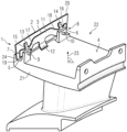
- the Figure shows a perspective view of a vane with the sealing device.
- a sealing device 1 for a flow machine comprises a flap seal 2, a surface 4, a first protrusion 5 protruding from the surface 4, a second protrusion 6 protruding from the surface 4 and a biasing means 3.
- the first protrusion 5 and the second protrusion 6 are arranged at a distance to each other.
- the biasing means 3 is supported on the first protrusion 5 and the second protrusion 6 and is adapted to push the flap seal 2 away from the first protrusion 5 and the second protrusion 6 in a direction transversal to the normal 23 of the surface 4.
- the biasing means 3 comprises a foot 12 that protrudes from a first region of the biasing means 3 in a direction towards the surface 4, wherein the first region is arranged immediately neighboured to the foot 12, wherein the foot 12 contacts the surface 4 and biases the remaining biasing means 3 in a direction away from the first protrusion 5 and the second protrusion 6.
- the flap seal 2 can have the shape of a plate, wherein the largest surface or one of the largest surfaces of the plate can be in particular rectangular, see the Figure.
- An angle between the largest surface or one of the largest surfaces of the plate and the normal 23 can for example be from 0° to 20°, in particular from 0° to 10°.
- the flap seal 2 can have a lower end 19 facing towards the surface 4 and an upper end 20 facing away from the surface 4.
- the lower end 19 and the upper end 20 can be parallel to each other.
- the lower end 19 and the upper end 20 can be parallel to the surface 4.
- the sealing device 1 can comprise a third protrusion 24 that protrudes in a direction away from the surface 4, is arranged on a side of the flap seal 2 and contacts the flap seal 2, wherein the side of the flap seal 2 faces away from the first protrusion 5 and the second protrusion 6.
- the biasing means 3 is thereby adapted to push the flap seal 2 against the third protrusion 24.
- the third protrusion 24 can protrude from the surface 4, as shown in the Figure, or can protrude from a part of the sealing device 1, wherein the part is different from the surface 4.
- the sealing device 1 can comprise a first bearing 7 that is adapted to support the biasing means 3 such that the biasing means 3 can tilt with respect to the first protrusion 5.
- the sealing device 1 can furthermore comprise a second bearing 8 that is adapted to support the biasing means 3 such that the biasing means 3 can tilt with respect to the second protrusion 6.
- the sealing device 4 is adapted such that the flap seal 2 can tilt around the lower end 19.
- the first bearing 7 can be formed by a first bearing part 15 of the biasing means 3 and a first rod 9 that extends through a through hole in the first protrusion 5 and a through hole in the first bearing part 15.
- a clearance between the first rod 9 and an edge of the through hole in the first bearing part 15 can be dimensioned such that the biasing means 3 can tilt with respect to the first protrusion 5.
- the first rod 9 can be fixedly attached to the first protrusion 5.
- the first rod 9 can comprise a head (not shown) having a larger diameter than a part of the first rod 9, wherein the part of the first rod 9 is arranged immediately neighboured to the head, so that the first bearing part 15 is confined between the head of the first rod 9 and the first protrusion 5.
- the second bearing 8 can be formed by a second bearing part 16 of the biasing means 3 and a second rod 10 that extends through a through hole in the second protrusion 6 and a through hole in the second bearing part 16.
- a clearance between the second rod 10 and an edge of the through hole in the second bearing part 16 can be dimensioned such that the biasing means 3 can tilt with respect to the second protrusion 6.
- the second rod 10 can be fixedly attached to the second protrusion 6.
- the second rod 10 can comprise a head (not shown) having a larger diameter than a part of the second rod 10, wherein the part of the second rod 10 is arranged immediately neighboured to the head, so that the second bearing part 16 is confined between the head of the second rod 10 and the second protrusion 6.
- the biasing means 3 can comprise a contacting part 11 that contacts the flap seal 2 and is arranged between the first protrusion 5 and the second protrusion 6.
- the contacting part 11 can comprise the first region.
- the contacting part 11 can for example contact the largest or one of the largest surfaces of the flap seal 2.
- the biasing means 3 can comprise a first connecting arm 17 that is attached on a first end of the contacting part 11 and a second connecting arm 18 that is attached on a second end of the contacting part 11, wherein the second end is facing away from the first end.
- the first connecting arm 17 connects the contacting part 11 to the first bearing part 15 and the second connecting arm 18 connects the contacting part 11 to the second bearing part 16.
- a respective angle can be formed by the first bearing part 15 and the first connecting arm 17, by the first connecting arm 17 and the contacting part 11, by the contacting part 11 and the second connecting arm 18 and by the second connecting arm 18 and the second bearing part 16.
- the foot 12 can have a curved shape, see the Figure, wherein the foot 12 is adapted to become less curved when the contacting part 11 is displaced away from the first protrusion 5 and the second protrusion 6.
- the foot 12 can be under a mechanical tension that becomes weaker when the contacting part 11 is displaced away from the first protrusion 5 and the second protrusion 6.
- the biasing means 3 can comprise a first arm 13 that protrudes from a second region of the biasing means 3 in a direction away from the surface 4, contacts the flap seal 2 and is arranged at a distance from the contacting part 11, wherein the second region is arranged immediately neighboured to the first arm 13.
- the second region can comprise the first bearing part 15.
- the biasing means 3 can comprise a second arm 14 that protrudes from a third region of the biasing means 3 in a direction away from the surface 4, contacts the flap seal 2 and is arranged at a distance from the contacting part 11, wherein the third region is arranged immediately neighboured to the second arm 14 and the contacting part 11 is arranged in a direction from the first protrusion 5 to the second protrusion 6 between the first arm 13 and the second arm 14.
- the third region can comprise the second bearing part 16.
- the contacting part 11, the first arm 13 and/or the second arm 14 can contact the flap seal 2 in a middle between the lower end 19 and the upper end 20, see the Figure.
- the first rod 9, in particular the complete first rod 9, can be arranged in the direction of the normal 23 between the middle and the surface 4.
- the second rod 10, in particular the complete second rod 10, can be arranged in the direction of the normal 23 between the middle and the surface 4.
- the Figure shows that the sealing part 1 can be part of a flow machine.
- the middle of the flap seal 2, wherein the middle is contacted by the contacting part 11, can be arranged in a middle between the lower end 19 and the upper end 20 in a radial direction of the flow machine.
- the surface 4 can be formed by a blade root 21 of the flow machine.
- the flow machine can be a gas turbine or a steam turbine.
- the blade can be a guiding vane 22 or a rotating blade of a compressor section or turbine section of the gas turbine.
- the blade also be a guiding vane 22 or a rotating blade of the steam turbine.
Landscapes
- Engineering & Computer Science (AREA)
- General Engineering & Computer Science (AREA)
- Mechanical Engineering (AREA)
- Structures Of Non-Positive Displacement Pumps (AREA)
- Sealing Using Fluids, Sealing Without Contact, And Removal Of Oil (AREA)
- Package Closures (AREA)
Abstract
The invention relates to a sealing device (1) for a flow machine, wherein the sealing device (1) comprises a flap seal (2), a surface (4), a first protrusion (5) protruding from the surface (4), a second protrusion (6) protruding from the surface (4) and a biasing means (3) that is supported on the first protrusion (5) and the second protrusion (6) and is adapted to push the flap seal (2) away from the first protrusion (5) and the second protrusion (6) in a direction transversal to the normal (23) of the surface (4), wherein the biasing means (3) comprises a foot (12) that protrudes from a first region of the biasing means (3) in a direction towards the surface (4), wherein the first region is arranged immediately neighboured to the foot (12), wherein the foot (12) contacts the surface (4) and biases the remaining biasing means (3) in a direction away from the first protrusion (5) and the second protrusion (6).
Description
- Flap seals are conventionally provided for sealing gaps, in particular in a flow machine. The sealing of the gaps in a flow machine reduces a leakage within the flow machine and therefore leads to an increased efficiency of the flow machine. Flap seals are conventionally pushed by a spring against the gap for which the spring has to be supported. In order to support the springs, space consuming structures have to be provided. These space consuming structures lead to increased costs and less available space.
- Therefore, it is an object of the invention to provide a sealing device for a flow machine and the flow machine with the sealing device, wherein the sealing device requires only a small amount of space.
- The inventive sealing device for a flow machine comprises a flap seal, a surface, a first protrusion protruding from the surface, a second protrusion protruding from the surface and a biasing means that is supported on the first protrusion and the second protrusion and is adapted to push the flap seal away from the first protrusion and the second protrusion in a direction transversal to the normal of the surface, wherein the biasing means comprises a foot that protrudes from a first region of the biasing means in a direction towards the surface, wherein the first region is arranged immediately neighboured to the foot, wherein the foot contacts the surface and biases the remaining biasing means in a direction away from the first protrusion and the second protrusion.
- By providing the foot that contacts the surface, the remaining biasing means, in particular the first region, is biased in a direction away from the first protrusion and the second protrusion. It is therefore not required to provide a spring at a distance from the surface in which the first region is arranged. The spring would have to be supported by the first protrusion and/or the second protrusion. The first protrusion and/or the second protrusion therefore do not need to be formed so high that they reach the distance of the first region from the surface but can advantageously be formed lower. Thereby, the first protrusion and the second protrusion can be formed such that they only need a small amount of space. This results therein that the sealing device can be made cost efficient.
- For biasing the biasing means the foot can be under a mechanical tension. The mechanical tension can increase if the first region is displaced towards the first protrusion and the second protrusion and the mechanical tension can decrease if the first region is displaced away from the first protrusion and the second protrusion.
- It is preferred that the biasing means comprises a contacting part that contacts the flap seal and is arranged between the first protrusion and the second protrusion. It is in particular preferred that the contacting part comprises the first region.
- The foot preferably has a curved shape, wherein the foot is adapted to become less curved when the contacting part is displaced away from the first protrusion and the second protrusion.
- It is preferred that the biasing means comprises a first arm that protrudes from a second region of the biasing means in a direction away from the surface, contacts the flap seal and is arranged at a distance from the contacting part, wherein the second region is arranged immediately neighboured to the first arm. The flap seal is thereby supported by the biasing means on more than one location which increases the sealing performance of the flap seal.
- The biasing means preferably comprises a second arm that protrudes from a third region of the biasing means in a direction away from the surface, contacts the flap seal and is arranged at a distance from the contacting part, wherein the third region is arranged immediately neighboured to the second arm and the contacting part is arranged between the first arm and the second arm. By providing the second arm, the sealing performance of the flap seal can be further increased.
- It is preferred that the flap seal has a lower end facing towards the surface and an upper end facing away from the surface, wherein the contacting part contacts the flap seal in a middle between the lower end and the upper end. It was surprisingly found that a wear of the flap seal can be minimized if the biasing means contacts the flap seal in the middle. It is particularly preferred that the lower end and the upper end are parallel to each other and in particular parallel to the surface. It is also preferred that the first arm and the second arm contact the flap seal in the middle, whereby wear of the flap seal can be further reduced.
- The sealing device is preferably adapted such that the flap seal can tilt around the lower end.
- It is preferred that the sealing device comprises a third protrusion that protrudes away from the surface, is arranged on a side of the flap seal and contacts the flap seal, wherein the side of the flap seal faces away from the first protrusion and the second protrusion. The lower end can for example be arranged in a corner that is formed by the surface and the third protrusion. By doing so, it is possible that the flap seal can tilt around the lower end.
- The sealing device preferably comprises a first bearing that is adapted to support the biasing means such that the biasing means can tilt with respect to the first protrusion, wherein the sealing device preferably comprises a second bearing that is adapted to support the biasing means such that the biasing means can tilt with respect to the second protrusion. The first bearing and/or the second bearing are preferably arranged at a distance from the surface, wherein the distance is shorter than the distance from the surface to the middle of the flap. An upper end of the first bearing and/or the second bearing is particularly preferred arranged at the distance from the surface, wherein the upper end is facing away from the surface.
- The flow machine according to the invention comprises the sealing device. The flow machine can for example be a steam turbine or a gas turbine. The sealing device can for example be arranged in a compressor section and/or a turbine section of the gas turbine.
- It is preferred that the surface is formed by a blade root of a blade of the flow machine. The blade can for example be a guiding vane of the compressor section, a rotating blade of the compressor section, a guiding vane of the turbine section or a rotating blade of the turbine section. The blade can for example also be a guiding vane of a steam turbine or a rotating blade of a steam turbine.
- In the following, the invention is explained on the basis of a schematic drawing. The Figure shows a perspective view of a vane with the sealing device.
- As it can be seen from the Figure, a sealing device 1 for a flow machine comprises a flap seal 2, a
surface 4, afirst protrusion 5 protruding from thesurface 4, asecond protrusion 6 protruding from thesurface 4 and a biasing means 3. Thefirst protrusion 5 and thesecond protrusion 6 are arranged at a distance to each other. The biasing means 3 is supported on thefirst protrusion 5 and thesecond protrusion 6 and is adapted to push the flap seal 2 away from thefirst protrusion 5 and thesecond protrusion 6 in a direction transversal to the normal 23 of thesurface 4. The biasing means 3 comprises afoot 12 that protrudes from a first region of the biasing means 3 in a direction towards thesurface 4, wherein the first region is arranged immediately neighboured to thefoot 12, wherein thefoot 12 contacts thesurface 4 and biases the remaining biasing means 3 in a direction away from thefirst protrusion 5 and thesecond protrusion 6. - The flap seal 2 can have the shape of a plate, wherein the largest surface or one of the largest surfaces of the plate can be in particular rectangular, see the Figure. An angle between the largest surface or one of the largest surfaces of the plate and the normal 23 can for example be from 0° to 20°, in particular from 0° to 10°. The flap seal 2 can have a lower end 19 facing towards the
surface 4 and anupper end 20 facing away from thesurface 4. The lower end 19 and theupper end 20 can be parallel to each other. In addition, the lower end 19 and theupper end 20 can be parallel to thesurface 4. - The Figure shows that the sealing device 1 can comprise a
third protrusion 24 that protrudes in a direction away from thesurface 4, is arranged on a side of the flap seal 2 and contacts the flap seal 2, wherein the side of the flap seal 2 faces away from thefirst protrusion 5 and thesecond protrusion 6. The biasing means 3 is thereby adapted to push the flap seal 2 against thethird protrusion 24. Thethird protrusion 24 can protrude from thesurface 4, as shown in the Figure, or can protrude from a part of the sealing device 1, wherein the part is different from thesurface 4. - The sealing device 1 can comprise a first bearing 7 that is adapted to support the biasing means 3 such that the biasing means 3 can tilt with respect to the
first protrusion 5. The sealing device 1 can furthermore comprise a second bearing 8 that is adapted to support the biasing means 3 such that the biasing means 3 can tilt with respect to thesecond protrusion 6. In the case that the biasing means 3 pushes the flap seal 2 against thethird protrusion 24 and the lower end 19 is arranged in a corner formed by thethird protrusion 24 and thesurface 4, thesealing device 4 is adapted such that the flap seal 2 can tilt around the lower end 19. - The first bearing 7 can be formed by a first bearing
part 15 of the biasing means 3 and afirst rod 9 that extends through a through hole in thefirst protrusion 5 and a through hole in the first bearingpart 15. A clearance between thefirst rod 9 and an edge of the through hole in the first bearingpart 15 can be dimensioned such that the biasing means 3 can tilt with respect to thefirst protrusion 5. Thefirst rod 9 can be fixedly attached to thefirst protrusion 5. Furthermore, thefirst rod 9 can comprise a head (not shown) having a larger diameter than a part of thefirst rod 9, wherein the part of thefirst rod 9 is arranged immediately neighboured to the head, so that the first bearingpart 15 is confined between the head of thefirst rod 9 and thefirst protrusion 5. Analogously, the second bearing 8 can be formed by a second bearingpart 16 of the biasing means 3 and asecond rod 10 that extends through a through hole in thesecond protrusion 6 and a through hole in the second bearingpart 16. A clearance between thesecond rod 10 and an edge of the through hole in the second bearingpart 16 can be dimensioned such that the biasing means 3 can tilt with respect to thesecond protrusion 6. Thesecond rod 10 can be fixedly attached to thesecond protrusion 6. Furthermore, thesecond rod 10 can comprise a head (not shown) having a larger diameter than a part of thesecond rod 10, wherein the part of thesecond rod 10 is arranged immediately neighboured to the head, so that the second bearingpart 16 is confined between the head of thesecond rod 10 and thesecond protrusion 6. -
Figure 1 show that the biasing means 3 can comprise a contactingpart 11 that contacts the flap seal 2 and is arranged between thefirst protrusion 5 and thesecond protrusion 6. The contactingpart 11 can comprise the first region. The contactingpart 11 can for example contact the largest or one of the largest surfaces of the flap seal 2. The biasing means 3 can comprise a first connectingarm 17 that is attached on a first end of the contactingpart 11 and a second connectingarm 18 that is attached on a second end of the contactingpart 11, wherein the second end is facing away from the first end. The first connectingarm 17 connects the contactingpart 11 to thefirst bearing part 15 and the second connectingarm 18 connects the contactingpart 11 to thesecond bearing part 16. A respective angle can be formed by thefirst bearing part 15 and the first connectingarm 17, by the first connectingarm 17 and the contactingpart 11, by the contactingpart 11 and the second connectingarm 18 and by the second connectingarm 18 and thesecond bearing part 16. - The
foot 12 can have a curved shape, see the Figure, wherein thefoot 12 is adapted to become less curved when the contactingpart 11 is displaced away from thefirst protrusion 5 and thesecond protrusion 6. Thefoot 12 can be under a mechanical tension that becomes weaker when the contactingpart 11 is displaced away from thefirst protrusion 5 and thesecond protrusion 6. - As it can be seen from the Figure, the biasing means 3 can comprise a
first arm 13 that protrudes from a second region of the biasing means 3 in a direction away from thesurface 4, contacts the flap seal 2 and is arranged at a distance from the contactingpart 11, wherein the second region is arranged immediately neighboured to thefirst arm 13. The second region can comprise thefirst bearing part 15. The biasing means 3 can comprise asecond arm 14 that protrudes from a third region of the biasing means 3 in a direction away from thesurface 4, contacts the flap seal 2 and is arranged at a distance from the contactingpart 11, wherein the third region is arranged immediately neighboured to thesecond arm 14 and the contactingpart 11 is arranged in a direction from thefirst protrusion 5 to thesecond protrusion 6 between thefirst arm 13 and thesecond arm 14. The third region can comprise thesecond bearing part 16. - The contacting
part 11, thefirst arm 13 and/or thesecond arm 14 can contact the flap seal 2 in a middle between the lower end 19 and theupper end 20, see the Figure. Thefirst rod 9, in particular the completefirst rod 9, can be arranged in the direction of the normal 23 between the middle and thesurface 4. Thesecond rod 10, in particular the completesecond rod 10, can be arranged in the direction of the normal 23 between the middle and thesurface 4. - The Figure shows that the sealing part 1 can be part of a flow machine. The middle of the flap seal 2, wherein the middle is contacted by the contacting
part 11, can be arranged in a middle between the lower end 19 and theupper end 20 in a radial direction of the flow machine. - The
surface 4 can be formed by ablade root 21 of the flow machine. The flow machine can be a gas turbine or a steam turbine. The blade can be a guidingvane 22 or a rotating blade of a compressor section or turbine section of the gas turbine. The blade also be a guidingvane 22 or a rotating blade of the steam turbine.
Claims (13)
- Sealing device for a flow machine, wherein the sealing device (1) comprises a flap seal (2), a surface (4), a first protrusion (5) protruding from the surface (4), a second protrusion (6) protruding from the surface (4) and a biasing means (3) that is supported on the first protrusion (5) and the second protrusion (6) and is adapted to push the flap seal (2) away from the first protrusion (5) and the second protrusion (6) in a direction transversal to the normal (23) of the surface (4), wherein the biasing means (3) comprises a foot (12) that protrudes from a first region of the biasing means (3) in a direction towards the surface (4), wherein the first region is arranged immediately neighboured to the foot (12), wherein the foot (12) contacts the surface (4) and biases the remaining biasing means (3) in a direction away from the first protrusion (5) and the second protrusion (6).
- Sealing device according to claim 1, wherein the biasing means (3) comprises a contacting part (11) that contacts the flap seal (2) and is arranged between the first protrusion (5) and the second protrusion (6).
- Sealing device according to claim 2, wherein the contacting part (11) comprises the first region.
- Sealing device according to claim 2 or 3, wherein the foot (12) has a curved shape, wherein the foot (12) is adapted to become less curved when the contacting part (11) is displaced away from the first protrusion (5) and the second protrusion (6) .
- Sealing device according to any one of claims 2 to 4, wherein the biasing means (3) comprises a first arm (13) that protrudes from a second region of the biasing means (3) in a direction away from the surface (4), contacts the flap seal (2) and is arranged at a distance from the contacting part (11), wherein the second region is arranged immediately neighboured to the first arm (13).
- Sealing device according to claim 5, wherein the biasing means (3) comprises a second arm (14) that protrudes from a third region of the biasing means (3) in a direction away from the surface (4), contacts the flap seal (2) and is arranged at a distance from the contacting part (11), wherein the third region is arranged immediately neighboured to the second arm (14) and the contacting part (11) is arranged between the first arm (13) and the second arm (14).
- Sealing device according to any one of claims 2 to 6, wherein the flap seal (2) has a lower end (19) facing towards the surface (4) and an upper end (20) facing away from the surface (4), wherein the contacting part (11) contacts the flap seal (2) in a middle between the lower end (19) and the upper end (20).
- Sealing device according to claim 7, wherein the lower end (19) and the upper end (20) are parallel to each other and in particular parallel to the surface (4).
- Sealing device according to claim 7 or 8, wherein the sealing device (1) is adapted such that the flap seal (2) can tilt around the lower end (19).
- Sealing device according to any one of claims 1 to 9, wherein the sealing device comprises a third protrusion (24) that protrudes in a direction away from the surface (4), is arranged on a side of the flap seal (2) and contacts the flap seal (2), wherein the side of the flap seal (2) faces away from the first protrusion (5) and the second protrusion (6).
- Sealing device according to any one of claims 1 to 10, wherein the sealing device (1) comprises a first bearing (7) that is adapted to support the biasing means (3) such that the biasing means (3) can tilt with respect to the first protrusion (5), wherein the sealing device (1) comprises a second bearing (8) that is adapted to support the biasing means (3) such that the biasing means (3) can tilt with respect to the second protrusion (6).
- Flow machine with a sealing device (2) according to any one of claims 1 to 11.
- Flow machine according to claim 12, wherein the surface (4) is formed by a blade root (21) of the flow machine.
Priority Applications (6)
| Application Number | Priority Date | Filing Date | Title |
|---|---|---|---|
| EP21192697.7A EP4141219A1 (en) | 2021-08-24 | 2021-08-24 | Sealing device and flow machine with the sealing device |
| PCT/EP2022/071438 WO2023025520A1 (en) | 2021-08-24 | 2022-07-29 | Sealing device and flow machine with the sealing device |
| US18/682,902 US12523158B2 (en) | 2021-08-24 | 2022-07-29 | Sealing device and flow machine with the sealing device |
| EP22754438.4A EP4341534B1 (en) | 2021-08-24 | 2022-07-29 | Sealing device and flow machine with the sealing device |
| CN202280057433.3A CN117859000A (en) | 2021-08-24 | 2022-07-29 | Sealing device and flow machine having the same |
| ES22754438T ES3032310T3 (en) | 2021-08-24 | 2022-07-29 | Sealing device and flow machine with the sealing device |
Applications Claiming Priority (1)
| Application Number | Priority Date | Filing Date | Title |
|---|---|---|---|
| EP21192697.7A EP4141219A1 (en) | 2021-08-24 | 2021-08-24 | Sealing device and flow machine with the sealing device |
Publications (1)
| Publication Number | Publication Date |
|---|---|
| EP4141219A1 true EP4141219A1 (en) | 2023-03-01 |
Family
ID=77465832
Family Applications (2)
| Application Number | Title | Priority Date | Filing Date |
|---|---|---|---|
| EP21192697.7A Withdrawn EP4141219A1 (en) | 2021-08-24 | 2021-08-24 | Sealing device and flow machine with the sealing device |
| EP22754438.4A Active EP4341534B1 (en) | 2021-08-24 | 2022-07-29 | Sealing device and flow machine with the sealing device |
Family Applications After (1)
| Application Number | Title | Priority Date | Filing Date |
|---|---|---|---|
| EP22754438.4A Active EP4341534B1 (en) | 2021-08-24 | 2022-07-29 | Sealing device and flow machine with the sealing device |
Country Status (5)
| Country | Link |
|---|---|
| US (1) | US12523158B2 (en) |
| EP (2) | EP4141219A1 (en) |
| CN (1) | CN117859000A (en) |
| ES (1) | ES3032310T3 (en) |
| WO (1) | WO2023025520A1 (en) |
Citations (6)
| Publication number | Priority date | Publication date | Assignee | Title |
|---|---|---|---|---|
| US5118120A (en) * | 1989-07-10 | 1992-06-02 | General Electric Company | Leaf seals |
| EP1270875A2 (en) * | 2001-06-21 | 2003-01-02 | General Electric Company | Turbine leaf seal mounting with headless pins |
| US20090169370A1 (en) * | 2007-12-29 | 2009-07-02 | General Electric Company | Turbine nozzle segment |
| EP2530250A2 (en) * | 2011-06-01 | 2012-12-05 | Rolls-Royce plc | Flap seal spring and sealing apparatus |
| WO2019174788A1 (en) * | 2018-03-13 | 2019-09-19 | Nuovo Pignone Tecnologie - S.R.L. | A turbomachine sealing system and turbomachine including the sealing system |
| EP3736413A1 (en) * | 2019-05-10 | 2020-11-11 | Safran Aircraft Engines | Turbine engine module provided with a device for supporting sealing strips |
Family Cites Families (4)
| Publication number | Priority date | Publication date | Assignee | Title |
|---|---|---|---|---|
| FR2786222B1 (en) * | 1998-11-19 | 2000-12-29 | Snecma | LAMELLE SEALING DEVICE |
| US7419352B2 (en) * | 2006-10-03 | 2008-09-02 | General Electric Company | Methods and apparatus for assembling turbine engines |
| US8459041B2 (en) * | 2011-11-09 | 2013-06-11 | General Electric Company | Leaf seal for transition duct in turbine system |
| ES2684387T3 (en) * | 2015-05-08 | 2018-10-02 | MTU Aero Engines AG | Turbomachine with a shutter |
-
2021
- 2021-08-24 EP EP21192697.7A patent/EP4141219A1/en not_active Withdrawn
-
2022
- 2022-07-29 CN CN202280057433.3A patent/CN117859000A/en active Pending
- 2022-07-29 US US18/682,902 patent/US12523158B2/en active Active
- 2022-07-29 ES ES22754438T patent/ES3032310T3/en active Active
- 2022-07-29 EP EP22754438.4A patent/EP4341534B1/en active Active
- 2022-07-29 WO PCT/EP2022/071438 patent/WO2023025520A1/en not_active Ceased
Patent Citations (6)
| Publication number | Priority date | Publication date | Assignee | Title |
|---|---|---|---|---|
| US5118120A (en) * | 1989-07-10 | 1992-06-02 | General Electric Company | Leaf seals |
| EP1270875A2 (en) * | 2001-06-21 | 2003-01-02 | General Electric Company | Turbine leaf seal mounting with headless pins |
| US20090169370A1 (en) * | 2007-12-29 | 2009-07-02 | General Electric Company | Turbine nozzle segment |
| EP2530250A2 (en) * | 2011-06-01 | 2012-12-05 | Rolls-Royce plc | Flap seal spring and sealing apparatus |
| WO2019174788A1 (en) * | 2018-03-13 | 2019-09-19 | Nuovo Pignone Tecnologie - S.R.L. | A turbomachine sealing system and turbomachine including the sealing system |
| EP3736413A1 (en) * | 2019-05-10 | 2020-11-11 | Safran Aircraft Engines | Turbine engine module provided with a device for supporting sealing strips |
Also Published As
| Publication number | Publication date |
|---|---|
| CN117859000A (en) | 2024-04-09 |
| EP4341534A1 (en) | 2024-03-27 |
| ES3032310T3 (en) | 2025-07-17 |
| EP4341534B1 (en) | 2025-03-05 |
| EP4341534C0 (en) | 2025-03-05 |
| US20250137384A1 (en) | 2025-05-01 |
| WO2023025520A1 (en) | 2023-03-02 |
| US12523158B2 (en) | 2026-01-13 |
Similar Documents
| Publication | Publication Date | Title |
|---|---|---|
| US6854736B2 (en) | Seal assembly for a rotary machine | |
| US7311495B2 (en) | Vane support in a gas turbine engine | |
| EP1995465B1 (en) | Barrier sealing system for centrifugal compressors | |
| US8025296B2 (en) | Shaft sealing mechanism | |
| CN1318138A (en) | Sealing system, esp for rotary machine | |
| CN101943152B (en) | Multistage compressor and oscillating piston | |
| US20220065123A1 (en) | Labyrinth sealing device | |
| US9677669B2 (en) | Shaft seal device and rotary machine | |
| JP5848372B2 (en) | Shaft seal device and rotary machine | |
| JP6430459B2 (en) | Turbine sealing structure | |
| EP4141219A1 (en) | Sealing device and flow machine with the sealing device | |
| RU2300033C2 (en) | Device for sealing slot between two parts | |
| US20220307603A1 (en) | Non-contact seal assembly with damping elements | |
| JP4643228B2 (en) | Shaft seal | |
| KR20090040956A (en) | Bearing Seals for Gas Turbines | |
| JP3917997B2 (en) | Shaft seal mechanism | |
| JP5653801B2 (en) | Rotary shaft seal structure | |
| KR102788709B1 (en) | Dynamic pressure shaft sealing device for fluid machine | |
| JP6276209B2 (en) | Turbine sealing device and turbine, and thin plate for sealing device | |
| CN224214374U (en) | A spring mounting structure for a scroll compressor and the scroll compressor | |
| CN208473939U (en) | Labyrinth-type excluder and steam turbine | |
| JP2006132636A (en) | Shaft seal and rotating machine | |
| JP5657268B2 (en) | Shaft seal device | |
| KR20240093018A (en) | Leaf spring and sealing module comprising the same | |
| KR20200090903A (en) | Thread segment and spinning machine |
Legal Events
| Date | Code | Title | Description |
|---|---|---|---|
| PUAI | Public reference made under article 153(3) epc to a published international application that has entered the european phase |
Free format text: ORIGINAL CODE: 0009012 |
|
| STAA | Information on the status of an ep patent application or granted ep patent |
Free format text: STATUS: THE APPLICATION HAS BEEN PUBLISHED |
|
| AK | Designated contracting states |
Kind code of ref document: A1 Designated state(s): AL AT BE BG CH CY CZ DE DK EE ES FI FR GB GR HR HU IE IS IT LI LT LU LV MC MK MT NL NO PL PT RO RS SE SI SK SM TR |
|
| STAA | Information on the status of an ep patent application or granted ep patent |
Free format text: STATUS: THE APPLICATION IS DEEMED TO BE WITHDRAWN |
|
| 18D | Application deemed to be withdrawn |
Effective date: 20230902 |