EP4141200A1 - Door lock with authentication module - Google Patents
Door lock with authentication module Download PDFInfo
- Publication number
- EP4141200A1 EP4141200A1 EP22191131.6A EP22191131A EP4141200A1 EP 4141200 A1 EP4141200 A1 EP 4141200A1 EP 22191131 A EP22191131 A EP 22191131A EP 4141200 A1 EP4141200 A1 EP 4141200A1
- Authority
- EP
- European Patent Office
- Prior art keywords
- authentication module
- door
- lock
- handle assembly
- door lock
- Prior art date
- Legal status (The legal status is an assumption and is not a legal conclusion. Google has not performed a legal analysis and makes no representation as to the accuracy of the status listed.)
- Pending
Links
- 238000004891 communication Methods 0.000 claims description 6
- 230000003068 static effect Effects 0.000 claims description 5
- 238000001514 detection method Methods 0.000 claims description 2
- 230000001815 facial effect Effects 0.000 description 4
- 238000010586 diagram Methods 0.000 description 3
- 239000000463 material Substances 0.000 description 2
- 230000037361 pathway Effects 0.000 description 2
- 238000011012 sanitization Methods 0.000 description 2
- 230000005540 biological transmission Effects 0.000 description 1
- 230000001413 cellular effect Effects 0.000 description 1
- 238000004140 cleaning Methods 0.000 description 1
- 239000012530 fluid Substances 0.000 description 1
- 239000004973 liquid crystal related substance Substances 0.000 description 1
- 238000012423 maintenance Methods 0.000 description 1
- 238000005259 measurement Methods 0.000 description 1
- 238000000034 method Methods 0.000 description 1
- 239000003595 mist Substances 0.000 description 1
- 230000000116 mitigating effect Effects 0.000 description 1
- 238000012986 modification Methods 0.000 description 1
- 230000004048 modification Effects 0.000 description 1
Images






Classifications
-
- E—FIXED CONSTRUCTIONS
- E05—LOCKS; KEYS; WINDOW OR DOOR FITTINGS; SAFES
- E05B—LOCKS; ACCESSORIES THEREFOR; HANDCUFFS
- E05B1/00—Knobs or handles for wings; Knobs, handles, or press buttons for locks or latches on wings
- E05B1/003—Handles pivoted about an axis perpendicular to the wing
-
- G—PHYSICS
- G07—CHECKING-DEVICES
- G07C—TIME OR ATTENDANCE REGISTERS; REGISTERING OR INDICATING THE WORKING OF MACHINES; GENERATING RANDOM NUMBERS; VOTING OR LOTTERY APPARATUS; ARRANGEMENTS, SYSTEMS OR APPARATUS FOR CHECKING NOT PROVIDED FOR ELSEWHERE
- G07C9/00—Individual registration on entry or exit
- G07C9/00174—Electronically operated locks; Circuits therefor; Nonmechanical keys therefor, e.g. passive or active electrical keys or other data carriers without mechanical keys
- G07C9/00563—Electronically operated locks; Circuits therefor; Nonmechanical keys therefor, e.g. passive or active electrical keys or other data carriers without mechanical keys using personal physical data of the operator, e.g. finger prints, retinal images, voicepatterns
-
- E—FIXED CONSTRUCTIONS
- E05—LOCKS; KEYS; WINDOW OR DOOR FITTINGS; SAFES
- E05B—LOCKS; ACCESSORIES THEREFOR; HANDCUFFS
- E05B1/00—Knobs or handles for wings; Knobs, handles, or press buttons for locks or latches on wings
- E05B1/0084—Handles or knobs with displays, signs, labels pictures, or the like
-
- E—FIXED CONSTRUCTIONS
- E05—LOCKS; KEYS; WINDOW OR DOOR FITTINGS; SAFES
- E05B—LOCKS; ACCESSORIES THEREFOR; HANDCUFFS
- E05B47/00—Operating or controlling locks or other fastening devices by electric or magnetic means
- E05B47/0001—Operating or controlling locks or other fastening devices by electric or magnetic means with electric actuators; Constructional features thereof
-
- G—PHYSICS
- G07—CHECKING-DEVICES
- G07C—TIME OR ATTENDANCE REGISTERS; REGISTERING OR INDICATING THE WORKING OF MACHINES; GENERATING RANDOM NUMBERS; VOTING OR LOTTERY APPARATUS; ARRANGEMENTS, SYSTEMS OR APPARATUS FOR CHECKING NOT PROVIDED FOR ELSEWHERE
- G07C9/00—Individual registration on entry or exit
- G07C9/00174—Electronically operated locks; Circuits therefor; Nonmechanical keys therefor, e.g. passive or active electrical keys or other data carriers without mechanical keys
-
- G—PHYSICS
- G07—CHECKING-DEVICES
- G07C—TIME OR ATTENDANCE REGISTERS; REGISTERING OR INDICATING THE WORKING OF MACHINES; GENERATING RANDOM NUMBERS; VOTING OR LOTTERY APPARATUS; ARRANGEMENTS, SYSTEMS OR APPARATUS FOR CHECKING NOT PROVIDED FOR ELSEWHERE
- G07C9/00—Individual registration on entry or exit
- G07C9/00174—Electronically operated locks; Circuits therefor; Nonmechanical keys therefor, e.g. passive or active electrical keys or other data carriers without mechanical keys
- G07C9/00896—Electronically operated locks; Circuits therefor; Nonmechanical keys therefor, e.g. passive or active electrical keys or other data carriers without mechanical keys specially adapted for particular uses
- G07C9/00904—Electronically operated locks; Circuits therefor; Nonmechanical keys therefor, e.g. passive or active electrical keys or other data carriers without mechanical keys specially adapted for particular uses for hotels, motels, office buildings or the like
-
- E—FIXED CONSTRUCTIONS
- E05—LOCKS; KEYS; WINDOW OR DOOR FITTINGS; SAFES
- E05B—LOCKS; ACCESSORIES THEREFOR; HANDCUFFS
- E05B17/00—Accessories in connection with locks
- E05B17/22—Means for operating or controlling lock or fastening device accessories, i.e. other than the fastening members, e.g. switches, indicators
- E05B17/226—Displays on locks, e.g. LED or LCD screens
-
- E—FIXED CONSTRUCTIONS
- E05—LOCKS; KEYS; WINDOW OR DOOR FITTINGS; SAFES
- E05B—LOCKS; ACCESSORIES THEREFOR; HANDCUFFS
- E05B35/00—Locks for use with special keys or a plurality of keys ; keys therefor
- E05B2035/009—Locks where a characteristic part of the user's body is used as a key
-
- E—FIXED CONSTRUCTIONS
- E05—LOCKS; KEYS; WINDOW OR DOOR FITTINGS; SAFES
- E05Y—INDEXING SCHEME ASSOCIATED WITH SUBCLASSES E05D AND E05F, RELATING TO CONSTRUCTION ELEMENTS, ELECTRIC CONTROL, POWER SUPPLY, POWER SIGNAL OR TRANSMISSION, USER INTERFACES, MOUNTING OR COUPLING, DETAILS, ACCESSORIES, AUXILIARY OPERATIONS NOT OTHERWISE PROVIDED FOR, APPLICATION THEREOF
- E05Y2400/00—Electronic control; Electrical power; Power supply; Power or signal transmission; User interfaces
- E05Y2400/80—User interfaces
- E05Y2400/81—Feedback to user, e.g. tactile
-
- G—PHYSICS
- G07—CHECKING-DEVICES
- G07C—TIME OR ATTENDANCE REGISTERS; REGISTERING OR INDICATING THE WORKING OF MACHINES; GENERATING RANDOM NUMBERS; VOTING OR LOTTERY APPARATUS; ARRANGEMENTS, SYSTEMS OR APPARATUS FOR CHECKING NOT PROVIDED FOR ELSEWHERE
- G07C9/00—Individual registration on entry or exit
- G07C9/00174—Electronically operated locks; Circuits therefor; Nonmechanical keys therefor, e.g. passive or active electrical keys or other data carriers without mechanical keys
- G07C2009/00753—Electronically operated locks; Circuits therefor; Nonmechanical keys therefor, e.g. passive or active electrical keys or other data carriers without mechanical keys operated by active electrical keys
- G07C2009/00769—Electronically operated locks; Circuits therefor; Nonmechanical keys therefor, e.g. passive or active electrical keys or other data carriers without mechanical keys operated by active electrical keys with data transmission performed by wireless means
Definitions
- the present invention relates to the art of a door lock, and more particularly, to a door lock that actuates in response to authentication information.
- Door locks that are operable in response to information or data that is recorded on a card and read by a card reader are commonly used, such as on a guest room door in a hotel.
- This kind of door lock may include a dead bolt or latch that is movable between an engaged and a disengaged position in conjunction with the rotation of a handle.
- the card reader is either located remotely from the door lock, or as shown in FIG. 1 , a portion of the door lock, such as the door handle 12 extends through a portion of the housing of the card reader 10.
- Typical configurations that have the door lock and the card reader co-located at the door provide limited accessibility of the card reader (e.g., the antenna of the card reader may be partially blocked by the handle and/or the antenna may only be able to read the card when the card is at a specific location), which results in less than ideal convenience for the end user.
- a system for a door includes a door lock having a handle assembly and a lock.
- the lock is movable between an engaged position and a disengaged position.
- An authentication module is mounted to the door lock at a position offset from a surface of the door. The authentication module is operably coupled to the lock.
- the authentication module is oriented at a non-parallel angle to the surface of the door.
- the authentication module is mounted adjacent to an end of the handle assembly.
- the authentication module includes a housing, the housing being integrally formed with the handle assembly.
- the authentication module and the handle assembly being movable about an axis of rotation in unison.
- the authentication module is coupled to the handle assembly, and at least a portion of the handle assembly is movable about an axis of rotation relative to the authentication module.
- the handle assembly further comprises a rod and a handle extending perpendicularly from the rod, the handle being movable relative to the authentication module.
- the authentication module is configured to actuate the lock from the engaged position to the disengaged position in response to receiving valid authentication data.
- the valid authentication data is provided by a portable device.
- the authentication module further comprises a housing; a cover connected to the housing to define a cavity between the housing and the cover; and a control board and at least one detector for receiving authentication data arranged within the cavity.
- a logo is displayed on the cover and a detection region associated with the at least one detector is arranged at a center of the logo.
- the authentication module is configured to perform a biometric recognition operation.
- the at least one detector is an antenna, and the antenna extends about a periphery of the cavity.
- the door lock further comprises an actuator connected to the lock, the control board being arranged in communication with the actuator.
- control board is hard-wired to the actuator via at least one wire.
- the at least one wire extends from the cavity through a portion of the handle assembly.
- control board is configured to wirelessly communicate with the actuator.
- a system for a door includes a door lock having a handle assembly and an authentication module mounted to the door lock at a position offset from a surface of the door.
- the authentication module includes a display screen operable to portray a message.
- the message is a static message.
- the authentication module further comprises a microphone and a speaker and the display screen is operable to perform a video conference.
- the door lock 22 may include a handle assembly 24 having a rod 26 that extends into or through a portion of the door 20 and a handle 28.
- the rod 26 is configured to define an axis of rotation X of the door lock 22.
- the handle 28 may be connected to a portion of the rod 26, near an end thereof arranged external to the door 20, such as in front of a surface 21 of the door 20.
- the handle 28 may extend substantially perpendicular to rod 26.
- the handle 28 may be integrally formed with the rod 26 such that the handle 28 and the rod 26 are configured to rotate about the axis of rotation X together in response to application of a force to the distal end 30 of the handle 28 for example.
- the door lock 22 may additionally include a cylinder 32 arranged within the interior of the door 20 and coupled directly to or indirectly to the rod 26.
- rotation of the handle 28 may cause the cylinder 32 and a respective latch 34 extending radially outwardly from the cylinder 32 to rotate and separate from a groove 36 of a corresponding faceplate arranged at an opposite surface, such as a wall or a doorframe for example.
- the door lock 22 may additionally include a lock 38, such as a deadbolt for example, located at position vertically offset from the cylinder 32 and/or the latch 34.
- the lock 38 may be configured to translate or slide along an axis Y in and out of the door 20 for engagement with another groove (not shown) formed in a wall or doorframe opposite the end of the door 20.
- a motor or actuator illustrated schematically at 40 in FIG. 8 , is arranged within the interior of the door 20 and is operably coupled to the lock 38.
- the actuator 40 may be selectively energized to drive movement of the lock 38 along its axis Y to actuate the lock 38 between an engaged position or locked position and a disengaged position or unlocked position. It should be understood that the configuration of the door lock 22 illustrated and described herein is intended as an example only and that a door lock 22 having any suitable configuration is within the scope of the disclosure.
- an authentication module 42 associated with the door lock 22 is mounted to the door 20 at a location or position offset from the surface 21 of the door 20.
- the authentication module 42 is mounted generally forward of or at a foremost end of the door lock 22.
- a desired logo such as a continuous circle for example, may be displayed on the authentication module 42 without interference by the door handle 28.
- the authentication module 42 may be oriented at a non-parallel angle (best shown in FIGS. 6A-6B ) to the adjacent surface 21 of the door 20, such that a contact surface 44 of the authentication module 42 faces upwardly, for example towards a ceiling.
- This non-parallel angle may provide increased accessibility to the authentication module 42 (e.g., by removing, or at least mitigating, the ability of the antenna of the authentication module from being blocked by the handle).
- the authentication module is arranged at a non-parallel angle between 30° and60° relative to the surface 21, for example at least 30°, at least 35°, at least 40°, at least 45°, at least 50°, at least 55°, and/or less than 60°.
- embodiments where the authentication module 42 is arranged at another angle, such as toward a side of the door 20 for example or embodiments where the authentication module 42 is oriented substantially parallel to the surface 21 of the door 20 are also within the scope of the disclosure.
- the authentication module 42 includes a base or housing 46 and the housing 46 is mounted to a portion of the rod 26 extending from the surface 21 of the door 20.
- the housing 46 may be integrally formed with the rod 26. As shown in FIGS. 7A and 7B . However, in other embodiments, the housing may be a separate component permanently affixed to the rod 26, or may be removably mounted to the rod 26. Further, as shown in FIGS. 7A and 7B , the housing 46 may be integrally formed with the handle, alternatively to or in addition to the rod 26. However, embodiments where the housing 46 is separate from and permanently affixed to the handle 28 or removably mounted to the handle 28 are also contemplated herein.
- the authentication module 42 may be configured to rotate about the axis of rotation X in unison with the handle 28.
- the handle 28 and/or the rod 26 may be configured to move, for example rotate, relative to the housing 46 of the authentication module 42.
- the housing 46 of the authentication module 42 may include a bottom 48 and one or more sidewalls 50 extending perpendicularly from the bottom 48 to define a cavity or hollow interior 52.
- a cover 54 such as formed from a plastic material for example, may be removably or permanently mounted to the sidewalls 50, opposite the bottom 48 to substantially seal the cavity 52 of the housing 46.
- the cover 54 may define the contact surface 44 of the authentication module 42.
- the electronic components of the authentication module 42 include at least one detector 62, such as an antenna, operably coupled to the control board 60.
- the at least one antenna 62 is configured to receive a transmission of data from a portable device 64, such as carried by a user or occupant.
- the antenna 62 may be located centrally relative to the housing 46 to facilitate communication between the antenna 62 and a portable device 64, such as a card for example, when the portable device 64 is brought to a position near a portion of the contact surface 44 of the authentication module 42.
- the antenna 62 may be mounted about a periphery of the interior surface of the cavity 52.
- an authentication module 42 having one or more antennas 62 located at any suitable location are within the scope of the disclosure.
- the antenna(s) 62 and the portable device 64 may be configured to communicate with one another via near field communication (NFC).
- NFC near field communication
- any other type of communication enabled by the portable device 64 and the antenna 62 such as Bluetooth, a local or public data network, radio frequency, a cellular network, or any other wired or wireless network for example, are also within the scope of the disclosure.
- the control board 60 of the authentication module 42 may be operably coupled to the actuator 40 of the door lock 22.
- the control board is configured to communicate one or more commands to the actuator 40 to selectively engage or disengage the lock 38.
- the control board 60 may communicate with the actuator 40 wirelessly, or alternatively, may communicate via one or more wires extending between the control board and the actuator 40 or a control associated with the actuator 40.
- a hole 66 is formed in the bottom 48 of the housing 46. This hole 66 may be aligned with the hollow interior of the rod 26 such that a continuous pathway extends from the cavity 52 of the housing 46 through the rod 26 to the actuator 40. Accordingly, in embodiments where the control board 60 and the actuator 40 are hard-wired together, one or more wires or cables may extend through the continuous pathway to couple the electronic components of the authentication module 42 with a portion of the door lock 22.
- the detector of the authentication module 42 is suitable to perform one or more types of biometric recognition, such as a facial recognition/authentication operation ( FIG. 10 ), a fingerprint recognition/authentication operation ( FIG. 11 ), and an iris recognition/authentication operation.
- the detector may be a camera.
- the detector 62 or region of the cover 54 associated with the detector 62 may be arranged at the center of a logo displayed on the cover 54.
- the authentication module 42 may be configured to adjust a position of the deadbolt 38 via the actuator 40 in response to valid authentication information being provided to the detector 62.
- a portion of the authentication module 42 such as a portion of the contact surface 44 for example, may be reflective to indicate to a user where to look to operate the door lock 22.
- the authentication module 42 may be operable to provide a status indicator to a user located near the door lock 22.
- at least one light emitting diode (LED) is arranged within the cavity 52 of the housing 46.
- At least a portion of the cover 54 of the authentication module 42 may be transparent and the one or more LEDs may be operable to illuminate one or more static display messages.
- the one or more LEDs may be operable to illuminate a display message that the "room requires cleaning", “do not disturb”, “welcome”, “low battery”, “maintenance is required” and/or any other suitable message.
- the one or more LEDs may be distinct components or may be part of a screen, such as a liquid crystal display (LCD) screen for example.
- a screen such as a liquid crystal display (LCD) screen for example.
- the screen may be formed as part of the cover, or may be arranged directly beneath the cover.
- the static messages are displayed within the center of the logo formed on the cover 54 or the LCD screen.
- the cover 54 of the authentication module or the LCD screen positioned adjacent to the cover 54 is operable as a video display panel.
- the electronic components of the authentication module 42 include a microphone and a speaker such that a user standing adjacent to the authentication module is able to interact with, and more specifically both hear and respond to, the message being played. Inclusion of the video display panel and the corresponding electronic components may allow the authentication module 42 to perform video conferencing (like facetime). Accordingly, operation of the authentication module 42 by a user may initiate a video call with an assistant, such as the front desk staff at a hotel for example.
- a container of sanitizer 68 may be arranged within cavity 52 of the housing 46 of the authentication module 42. Further, a plurality of holes (not shown) may be formed in the housing 46, such as in the bottom 48 and/or the sidewalls 50 thereof.
- the operation of the door lock 22 is configured to release sanitizer from the container 68 onto the handle 28 and/or the rod 26 via the holes formed in the housing 46.
- the sanitizer is released in the form of a mist or atomized fluid. Accordingly, in such embodiments, the door lock 22 and authentication module 42 may be considered to be self-sanitizing.
- a door lock 22 including an authentication module 42 located offset from the surface of the door as illustrated and described herein is able to more effectively receive a signal from a portable device 64 regardless of whether the portable device 64 is directly aligned with the antenna 62. Further, by locating the authentication module 42 at the front of the door handle 28, the authentication module 42 can be angled, thereby providing greater visibility to an operator and allowing for enhanced operations, such as facial recognition for example. In addition, this position of the authentication module 42 relative to the door handle 28 allows a desired logo to be displayed on the authentication module 42 without interference.
Landscapes
- Physics & Mathematics (AREA)
- General Physics & Mathematics (AREA)
- Lock And Its Accessories (AREA)
Abstract
Description
- The present invention relates to the art of a door lock, and more particularly, to a door lock that actuates in response to authentication information.
- Door locks that are operable in response to information or data that is recorded on a card and read by a card reader are commonly used, such as on a guest room door in a hotel. This kind of door lock may include a dead bolt or latch that is movable between an engaged and a disengaged position in conjunction with the rotation of a handle. In existing systems, the card reader is either located remotely from the door lock, or as shown in
FIG. 1 , a portion of the door lock, such as thedoor handle 12 extends through a portion of the housing of thecard reader 10. Typical configurations that have the door lock and the card reader co-located at the door provide limited accessibility of the card reader (e.g., the antenna of the card reader may be partially blocked by the handle and/or the antenna may only be able to read the card when the card is at a specific location), which results in less than ideal convenience for the end user. - According to a first aspect of the present invention, a system for a door includes a door lock having a handle assembly and a lock. The lock is movable between an engaged position and a disengaged position. An authentication module is mounted to the door lock at a position offset from a surface of the door. The authentication module is operably coupled to the lock.
- Optionally, the authentication module is oriented at a non-parallel angle to the surface of the door.
- Optionally the authentication module is mounted adjacent to an end of the handle assembly.
- Optionally the authentication module includes a housing, the housing being integrally formed with the handle assembly.
- Optionally the authentication module and the handle assembly being movable about an axis of rotation in unison.
- Optionally the authentication module is coupled to the handle assembly, and at least a portion of the handle assembly is movable about an axis of rotation relative to the authentication module.
- Optionally the handle assembly further comprises a rod and a handle extending perpendicularly from the rod, the handle being movable relative to the authentication module.
- Optionally the authentication module is configured to actuate the lock from the engaged position to the disengaged position in response to receiving valid authentication data.
- Optionally the valid authentication data is provided by a portable device.
- Optionally the authentication module further comprises a housing; a cover connected to the housing to define a cavity between the housing and the cover; and a control board and at least one detector for receiving authentication data arranged within the cavity.
- Optionally a logo is displayed on the cover and a detection region associated with the at least one detector is arranged at a center of the logo.
- Optionally the authentication module is configured to perform a biometric recognition operation.
- Optionally the at least one detector is an antenna, and the antenna extends about a periphery of the cavity.
- Optionally the door lock further comprises an actuator connected to the lock, the control board being arranged in communication with the actuator.
- Optionally the control board is hard-wired to the actuator via at least one wire.
- Optionally the at least one wire extends from the cavity through a portion of the handle assembly.
- Optionally the control board is configured to wirelessly communicate with the actuator.
- According to an embodiment a second aspect of the present invention, a system for a door includes a door lock having a handle assembly and an authentication module mounted to the door lock at a position offset from a surface of the door. The authentication module includes a display screen operable to portray a message.
- Optionally the message is a static message.
- Optionally the authentication module further comprises a microphone and a speaker and the display screen is operable to perform a video conference.
- The following descriptions should not be considered limiting in any way. With reference to the accompanying drawings, which are provided by way of example only, like elements are numbered alike:
-
FIG. 1 is a schematic diagram of an example of a prior art door including a door lock and a corresponding card reader; -
FIG. 2 is a cross-sectional schematic diagram of a door including a door lock and a corresponding authentication module; -
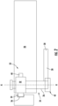
FIG. 3 is a front view of a door including a door lock and a corresponding authentication module; -
FIG. 4 is a perspective view of a door lock including an authentication module; -
FIG. 5 is a front view of the door lock ofFIG. 4 ; -
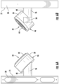
FIGS. 6A and 6B are side views of the door lock ofFIG. 4 ; -
FIG. 7A is a rear perspective view of the handle assembly and a portion of the authentication module; -
FIG. 7B is a front perspective view of the handle assembly and a portion of the authentication module; -
FIG. 8 is a schematic diagram of the communication between the door lock and the authentication module in response to a portable device; -
FIG. 9 is a perspective view of a door lock including an authentication module; -
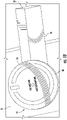
FIG. 10 is a perspective view of a door lock including an authentication module; -
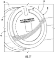
FIG. 11 is a detailed perspective view of an authentication module operable to perform a fingerprint authentication operation; and -
FIG. 12 is an exploded view of self-sanitizing authentication module. - A detailed description of one or more apparatus and method are presented herein by way of exemplification and not limitation with reference to the Figures.
- With reference now to
FIGS. 2-8 , an example of adoor 20 having anelectric door lock 22 and an authentication module associated with or operably coupled to the electric door lock is illustrated. As shown, thedoor lock 22 may include ahandle assembly 24 having arod 26 that extends into or through a portion of thedoor 20 and ahandle 28. Therod 26 is configured to define an axis of rotation X of thedoor lock 22. Thehandle 28 may be connected to a portion of therod 26, near an end thereof arranged external to thedoor 20, such as in front of asurface 21 of thedoor 20. In embodiments where thehandle 28 is a lever, thehandle 28 may extend substantially perpendicular to rod 26. Thehandle 28 may be integrally formed with therod 26 such that thehandle 28 and therod 26 are configured to rotate about the axis of rotation X together in response to application of a force to thedistal end 30 of thehandle 28 for example. - As shown in
FIG. 2 , thedoor lock 22 may additionally include acylinder 32 arranged within the interior of thedoor 20 and coupled directly to or indirectly to therod 26. In operation, rotation of thehandle 28 may cause thecylinder 32 and arespective latch 34 extending radially outwardly from thecylinder 32 to rotate and separate from agroove 36 of a corresponding faceplate arranged at an opposite surface, such as a wall or a doorframe for example. - With continued reference to
FIG. 2 and further reference toFIG. 3 , thedoor lock 22 may additionally include a lock 38, such as a deadbolt for example, located at position vertically offset from thecylinder 32 and/or thelatch 34. The lock 38 may be configured to translate or slide along an axis Y in and out of thedoor 20 for engagement with another groove (not shown) formed in a wall or doorframe opposite the end of thedoor 20. In an embodiment, a motor or actuator, illustrated schematically at 40 inFIG. 8 , is arranged within the interior of thedoor 20 and is operably coupled to the lock 38. Theactuator 40 may be selectively energized to drive movement of the lock 38 along its axis Y to actuate the lock 38 between an engaged position or locked position and a disengaged position or unlocked position. It should be understood that the configuration of thedoor lock 22 illustrated and described herein is intended as an example only and that adoor lock 22 having any suitable configuration is within the scope of the disclosure. - As shown, an
authentication module 42 associated with thedoor lock 22 is mounted to thedoor 20 at a location or position offset from thesurface 21 of thedoor 20. In the illustrated, non-limiting embodiment, theauthentication module 42 is mounted generally forward of or at a foremost end of thedoor lock 22. By positioning the authentication module at such a location, a desired logo, such as a continuous circle for example, may be displayed on theauthentication module 42 without interference by thedoor handle 28. Theauthentication module 42 may be oriented at a non-parallel angle (best shown inFIGS. 6A-6B ) to theadjacent surface 21 of thedoor 20, such that acontact surface 44 of theauthentication module 42 faces upwardly, for example towards a ceiling. This non-parallel angle may provide increased accessibility to the authentication module 42 (e.g., by removing, or at least mitigating, the ability of the antenna of the authentication module from being blocked by the handle). In an embodiment, the authentication module is arranged at a non-parallel angle between 30° and60° relative to thesurface 21, for example at least 30°, at least 35°, at least 40°, at least 45°, at least 50°, at least 55°, and/or less than 60°. However, embodiments where theauthentication module 42 is arranged at another angle, such as toward a side of thedoor 20 for example or embodiments where theauthentication module 42 is oriented substantially parallel to thesurface 21 of thedoor 20 are also within the scope of the disclosure. - In the illustrated, non-limiting embodiment, the
authentication module 42 includes a base orhousing 46 and thehousing 46 is mounted to a portion of therod 26 extending from thesurface 21 of thedoor 20. Thehousing 46 may be integrally formed with therod 26. As shown inFIGS. 7A and 7B . However, in other embodiments, the housing may be a separate component permanently affixed to therod 26, or may be removably mounted to therod 26. Further, as shown inFIGS. 7A and 7B , thehousing 46 may be integrally formed with the handle, alternatively to or in addition to therod 26. However, embodiments where thehousing 46 is separate from and permanently affixed to thehandle 28 or removably mounted to thehandle 28 are also contemplated herein. Accordingly, in such embodiments, theauthentication module 42 may be configured to rotate about the axis of rotation X in unison with thehandle 28. However, in other embodiments, thehandle 28 and/or therod 26 may be configured to move, for example rotate, relative to thehousing 46 of theauthentication module 42. - The
housing 46 of theauthentication module 42 may include a bottom 48 and one or more sidewalls 50 extending perpendicularly from the bottom 48 to define a cavity orhollow interior 52. Acover 54, such as formed from a plastic material for example, may be removably or permanently mounted to thesidewalls 50, opposite the bottom 48 to substantially seal thecavity 52 of thehousing 46. Thecover 54 may define thecontact surface 44 of theauthentication module 42. - One or more electronic components may be stored within the
cavity 52 of thehousing 46. In addition to acontrol board 60, in an embodiment, the electronic components of theauthentication module 42 include at least onedetector 62, such as an antenna, operably coupled to thecontrol board 60. The at least oneantenna 62 is configured to receive a transmission of data from a portable device 64, such as carried by a user or occupant. Theantenna 62 may be located centrally relative to thehousing 46 to facilitate communication between theantenna 62 and a portable device 64, such as a card for example, when the portable device 64 is brought to a position near a portion of thecontact surface 44 of theauthentication module 42. Alternatively, or in addition, theantenna 62 may be mounted about a periphery of the interior surface of thecavity 52. However, it should be understood that anauthentication module 42 having one ormore antennas 62 located at any suitable location are within the scope of the disclosure. - The antenna(s) 62 and the portable device 64 may be configured to communicate with one another via near field communication (NFC). However, any other type of communication enabled by the portable device 64 and the
antenna 62, such as Bluetooth, a local or public data network, radio frequency, a cellular network, or any other wired or wireless network for example, are also within the scope of the disclosure. - The
control board 60 of theauthentication module 42 may be operably coupled to theactuator 40 of thedoor lock 22. In an embodiment, the control board is configured to communicate one or more commands to theactuator 40 to selectively engage or disengage the lock 38. Thecontrol board 60 may communicate with theactuator 40 wirelessly, or alternatively, may communicate via one or more wires extending between the control board and theactuator 40 or a control associated with theactuator 40. In an embodiment, ahole 66 is formed in the bottom 48 of thehousing 46. Thishole 66 may be aligned with the hollow interior of therod 26 such that a continuous pathway extends from thecavity 52 of thehousing 46 through therod 26 to theactuator 40. Accordingly, in embodiments where thecontrol board 60 and theactuator 40 are hard-wired together, one or more wires or cables may extend through the continuous pathway to couple the electronic components of theauthentication module 42 with a portion of thedoor lock 22. - In an embodiment, the detector of the
authentication module 42 is suitable to perform one or more types of biometric recognition, such as a facial recognition/authentication operation (FIG. 10 ), a fingerprint recognition/authentication operation (FIG. 11 ), and an iris recognition/authentication operation. For example, in embodiments where the authentication module is configured to use facial recognition, the detector may be a camera. In such embodiments, thedetector 62 or region of thecover 54 associated with thedetector 62 may be arranged at the center of a logo displayed on thecover 54. As previously described, theauthentication module 42 may be configured to adjust a position of the deadbolt 38 via theactuator 40 in response to valid authentication information being provided to thedetector 62. In embodiments where theauthentication module 42 is configured to perform a facial recognition operation, a portion of theauthentication module 42, such as a portion of thecontact surface 44 for example, may be reflective to indicate to a user where to look to operate thedoor lock 22. - Alternatively, or in addition to the authentication and operation of the
door lock 22 described above, theauthentication module 42 may be operable to provide a status indicator to a user located near thedoor lock 22. In such embodiments, at least one light emitting diode (LED) is arranged within thecavity 52 of thehousing 46. At least a portion of thecover 54 of theauthentication module 42 may be transparent and the one or more LEDs may be operable to illuminate one or more static display messages. For example, as shown inFIGS. 4 ,5 , and9 , the one or more LEDs may be operable to illuminate a display message that the "room requires cleaning", "do not disturb", "welcome", "low battery", "maintenance is required" and/or any other suitable message. The one or more LEDs may be distinct components or may be part of a screen, such as a liquid crystal display (LCD) screen for example. In embodiments where the at least one LED is part of an LCD screen, the screen may be formed as part of the cover, or may be arranged directly beneath the cover. In an embodiment, the static messages are displayed within the center of the logo formed on thecover 54 or the LCD screen. - In addition to the static messages described above, in an embodiment, the
cover 54 of the authentication module or the LCD screen positioned adjacent to thecover 54 is operable as a video display panel. In such embodiments, the electronic components of theauthentication module 42 include a microphone and a speaker such that a user standing adjacent to the authentication module is able to interact with, and more specifically both hear and respond to, the message being played. Inclusion of the video display panel and the corresponding electronic components may allow theauthentication module 42 to perform video conferencing (like facetime). Accordingly, operation of theauthentication module 42 by a user may initiate a video call with an assistant, such as the front desk staff at a hotel for example. - With reference now to
FIG. 12 , in an embodiment, a container ofsanitizer 68 may be arranged withincavity 52 of thehousing 46 of theauthentication module 42. Further, a plurality of holes (not shown) may be formed in thehousing 46, such as in the bottom 48 and/or thesidewalls 50 thereof. In response to receipt of valid authentication data, the operation of thedoor lock 22 is configured to release sanitizer from thecontainer 68 onto thehandle 28 and/or therod 26 via the holes formed in thehousing 46. In an embodiment, the sanitizer is released in the form of a mist or atomized fluid. Accordingly, in such embodiments, thedoor lock 22 andauthentication module 42 may be considered to be self-sanitizing. - A
door lock 22 including anauthentication module 42 located offset from the surface of the door as illustrated and described herein is able to more effectively receive a signal from a portable device 64 regardless of whether the portable device 64 is directly aligned with theantenna 62. Further, by locating theauthentication module 42 at the front of thedoor handle 28, theauthentication module 42 can be angled, thereby providing greater visibility to an operator and allowing for enhanced operations, such as facial recognition for example. In addition, this position of theauthentication module 42 relative to thedoor handle 28 allows a desired logo to be displayed on theauthentication module 42 without interference. - The term "about" is intended to include the degree of error associated with measurement of the particular quantity based upon the equipment available at the time of filing the application.
- The terminology used herein is for the purpose of describing particular embodiments only and is not intended to be limiting of the present disclosure. As used herein, the singular forms "a", "an" and "the" are intended to include the plural forms as well, unless the context clearly indicates otherwise. It will be further understood that the terms "comprises" and/or "comprising," when used in this specification, specify the presence of stated features, integers, steps, operations, elements, and/or components, but do not preclude the presence or addition of one or more other features, integers, steps, operations, element components, and/or groups thereof.
- While the present disclosure has been described with reference to an exemplary embodiment or embodiments, it will be understood by those skilled in the art that various changes may be made and equivalents may be substituted for elements thereof without departing from the scope of the present disclosure. In addition, many modifications may be made to adapt a particular situation or material to the teachings of the present disclosure without departing from the essential scope thereof. Therefore, it is intended that the present disclosure not be limited to the particular embodiment disclosed as the best mode contemplated for carrying out this present disclosure, but that the present disclosure will include all embodiments falling within the scope of the claims.
Claims (15)
- A system for a door (20) comprising:a door lock (22) including a handle assembly (24) and a lock (38), the lock (38) being movable between an engaged position and a disengaged position; andan authentication module (42) mounted to the door lock (22) at a position offset from a surface of the door (20), the authentication module (42) being operably coupled to the lock (38).
- The system of claim 1, wherein the authentication module (42) is oriented at a non-parallel angle to the surface of the door.
- The system of claim 1 or 2, wherein the authentication module (42) is mounted adjacent to an end of the handle assembly (24).
- The system of claim 1, 2 or 3, wherein the authentication module (42) includes a housing (46), the housing (46) being integrally formed with the handle assembly (24).
- The system of any of claims 1 to 4, wherein the authentication module (42) and the handle assembly (24) are movable about an axis of rotation (X) in unison.
- The system of any of claims 1 to 4, wherein the authentication module (42) is coupled to the handle assembly (24), and at least a portion of the handle assembly (24) is movable about an axis of rotation (X) relative to the authentication module (42); and
optionally wherein the handle assembly (24) further comprises a rod (26) and a handle (28) extending perpendicularly from the rod (26), the handle (28) being movable relative to the authentication module (42). - The system of any of claims 1 to 6, wherein the authentication module (42) is configured to actuate the lock (38) from the engaged position to the disengaged position in response to receiving valid authentication data, and optionally wherein the valid authentication data is provided by a portable device (64).
- The system of claim 7, wherein the authentication module (42) further comprises:a housing (46);a cover (54) connected to the housing (46) to define a cavity (52) between the housing (46) and the cover (54), optionally wherein a logo is displayed on the cover (54) and a detection region associated with the at least one detector (62) is arranged at a center of the logo; anda control board (60) and at least one detector (62) for receiving authentication data arranged within the cavity (52).
- The system of claim 8, wherein the authentication module (42) is configured to perform a biometric recognition operation.
- The system of claim 8 or 9, wherein the at least one detector (62) is an antenna (62), and the antenna (62) extends about a periphery of the cavity (52).
- The system of claim 8, 9 or 10, wherein the door lock further comprises an actuator (40) connected to the lock (38), the control board (60) being arranged in communication with the actuator (40).
- The system of claim 11, wherein:the control board (60) is configured to wirelessly communicate with the actuator (40); orthe control board (60) is hard-wired to the actuator (40) via at least one wire, and optionally wherein the at least one wire extends from the cavity (52) through a portion of the handle assembly (24)
- A system for a door (20) comprising:a door lock (22) including a handle assembly (24); andan authentication module (42) mounted to the door lock (22) at a position offset from a surface of the door (20), the authentication module (42) including a display screen operable to portray a message.
- The system of claim 13, wherein the message is a static message.
- The system of claim 13 or 14, wherein the authentication module (42) further comprises a microphone and a speaker, and wherein the display screen is operable to perform a video conference.
Applications Claiming Priority (1)
| Application Number | Priority Date | Filing Date | Title |
|---|---|---|---|
| US202163237251P | 2021-08-26 | 2021-08-26 |
Publications (1)
| Publication Number | Publication Date |
|---|---|
| EP4141200A1 true EP4141200A1 (en) | 2023-03-01 |
Family
ID=83004895
Family Applications (1)
| Application Number | Title | Priority Date | Filing Date |
|---|---|---|---|
| EP22191131.6A Pending EP4141200A1 (en) | 2021-08-26 | 2022-08-19 | Door lock with authentication module |
Country Status (2)
| Country | Link |
|---|---|
| US (1) | US20230065459A1 (en) |
| EP (1) | EP4141200A1 (en) |
Citations (6)
| Publication number | Priority date | Publication date | Assignee | Title |
|---|---|---|---|---|
| WO2002095170A1 (en) * | 2001-05-19 | 2002-11-28 | Keico Hightech Inc. | Door lock handle with fingerprint recognition function |
| US10032327B1 (en) * | 2017-01-25 | 2018-07-24 | Beijing Jialan Technology Co., Ltd. | Access control system with facial recognition and unlocking method thereof |
| WO2018146460A1 (en) * | 2017-02-09 | 2018-08-16 | Ali Isameldin Omar | A door locking device and a smart door apparatus |
| US20180266145A1 (en) * | 2017-03-17 | 2018-09-20 | Kuo-Chi Chou | Door Handle with Electronic Lock Assembly |
| WO2019068021A1 (en) * | 2017-09-28 | 2019-04-04 | Gate Labs Inc. | Access systems and methods for use |
| CN110748241A (en) * | 2019-09-11 | 2020-02-04 | 珠海格力电器股份有限公司 | smart door lock |
Family Cites Families (6)
| Publication number | Priority date | Publication date | Assignee | Title |
|---|---|---|---|---|
| CN102906360B (en) * | 2010-03-02 | 2016-07-06 | Utc消防及保安公司 | Seamless Authentication System |
| MX355745B (en) * | 2013-03-15 | 2018-04-27 | Spectrum Brands Inc | Wireless lockset with integrated antenna, touch activation and light communication device. |
| US20160364009A1 (en) * | 2013-07-18 | 2016-12-15 | BOT Home Automation, Inc. | Gesture recognition for wireless audio/video recording and communication devices |
| US20180108192A1 (en) * | 2014-12-23 | 2018-04-19 | Gate Labs Inc. | Access management system |
| US10049520B2 (en) * | 2016-06-13 | 2018-08-14 | Sargent Manufacturing Company | Access system with persistent display |
| US10087652B2 (en) * | 2016-12-20 | 2018-10-02 | Schlage Lock Company Llc | Door lock having day-night visible keypad |
-
2022
- 2022-08-17 US US17/889,470 patent/US20230065459A1/en active Pending
- 2022-08-19 EP EP22191131.6A patent/EP4141200A1/en active Pending
Patent Citations (6)
| Publication number | Priority date | Publication date | Assignee | Title |
|---|---|---|---|---|
| WO2002095170A1 (en) * | 2001-05-19 | 2002-11-28 | Keico Hightech Inc. | Door lock handle with fingerprint recognition function |
| US10032327B1 (en) * | 2017-01-25 | 2018-07-24 | Beijing Jialan Technology Co., Ltd. | Access control system with facial recognition and unlocking method thereof |
| WO2018146460A1 (en) * | 2017-02-09 | 2018-08-16 | Ali Isameldin Omar | A door locking device and a smart door apparatus |
| US20180266145A1 (en) * | 2017-03-17 | 2018-09-20 | Kuo-Chi Chou | Door Handle with Electronic Lock Assembly |
| WO2019068021A1 (en) * | 2017-09-28 | 2019-04-04 | Gate Labs Inc. | Access systems and methods for use |
| CN110748241A (en) * | 2019-09-11 | 2020-02-04 | 珠海格力电器股份有限公司 | smart door lock |
Also Published As
| Publication number | Publication date |
|---|---|
| US20230065459A1 (en) | 2023-03-02 |
Similar Documents
| Publication | Publication Date | Title |
|---|---|---|
| KR101618541B1 (en) | Wireless lockset with integrated antenna, touch activation, and light communication device | |
| US10006246B2 (en) | On demand modular ingress/egress control mechanism | |
| WO2003100565A2 (en) | Mounted remote control unit with plug-in module interface | |
| US20020116969A1 (en) | Lock with sensor | |
| US20140300116A1 (en) | System For Interlocking and Unlocking a Sliding Door | |
| JP2007511729A (en) | refrigerator | |
| EP3611703B1 (en) | Remote control button actuator with removable tray | |
| US4167733A (en) | Tamper-proof security alarm system | |
| US20150033628A1 (en) | On Demand Modular Ingress/Egress Control Mechanism | |
| JP4216613B2 (en) | Crime prevention system | |
| US11199042B2 (en) | Multifunction lock unit | |
| KR20110007369A (en) | Window lock digital lock | |
| US20230065459A1 (en) | Door lock with authentication module | |
| US20210067747A1 (en) | Smart Visual Lock System | |
| KR101615455B1 (en) | Apparatus for tool storage | |
| KR101258310B1 (en) | Door control device | |
| US6116381A (en) | Passive hall fixtures mounted in elevator doors | |
| KR100544599B1 (en) | Digital door lock with external communication interface port for emergency release and control method | |
| JPH09184332A (en) | Sash | |
| CN210598457U (en) | Improved Cabinet Locks | |
| CN222339749U (en) | Wireless projection equipment | |
| US12104430B1 (en) | Room access control system with barrier arm having downwardly extending fan assembly | |
| US7709756B2 (en) | Safety switch | |
| JP2004326609A (en) | Crime prevention system | |
| JP4161199B2 (en) | Door phone |
Legal Events
| Date | Code | Title | Description |
|---|---|---|---|
| PUAI | Public reference made under article 153(3) epc to a published international application that has entered the european phase |
Free format text: ORIGINAL CODE: 0009012 |
|
| STAA | Information on the status of an ep patent application or granted ep patent |
Free format text: STATUS: THE APPLICATION HAS BEEN PUBLISHED |
|
| AK | Designated contracting states |
Kind code of ref document: A1 Designated state(s): AL AT BE BG CH CY CZ DE DK EE ES FI FR GB GR HR HU IE IS IT LI LT LU LV MC MK MT NL NO PL PT RO RS SE SI SK SM TR |
|
| STAA | Information on the status of an ep patent application or granted ep patent |
Free format text: STATUS: REQUEST FOR EXAMINATION WAS MADE |
|
| 17P | Request for examination filed |
Effective date: 20230901 |
|
| RBV | Designated contracting states (corrected) |
Designated state(s): AL AT BE BG CH CY CZ DE DK EE ES FI FR GB GR HR HU IE IS IT LI LT LU LV MC MK MT NL NO PL PT RO RS SE SI SK SM TR |
|
| RAP1 | Party data changed (applicant data changed or rights of an application transferred) |
Owner name: HONEYWELL INTERNATIONAL INC. |