EP4140897A1 - Adjustable port size insert - Google Patents
Adjustable port size insert Download PDFInfo
- Publication number
- EP4140897A1 EP4140897A1 EP22188728.4A EP22188728A EP4140897A1 EP 4140897 A1 EP4140897 A1 EP 4140897A1 EP 22188728 A EP22188728 A EP 22188728A EP 4140897 A1 EP4140897 A1 EP 4140897A1
- Authority
- EP
- European Patent Office
- Prior art keywords
- main body
- insert
- opening
- body opening
- cross
- Prior art date
- Legal status (The legal status is an assumption and is not a legal conclusion. Google has not performed a legal analysis and makes no representation as to the accuracy of the status listed.)
- Withdrawn
Links
Images


Classifications
-
- B—PERFORMING OPERATIONS; TRANSPORTING
- B64—AIRCRAFT; AVIATION; COSMONAUTICS
- B64G—COSMONAUTICS; VEHICLES OR EQUIPMENT THEREFOR
- B64G1/00—Cosmonautic vehicles
- B64G1/22—Parts of, or equipment specially adapted for fitting in or to, cosmonautic vehicles
- B64G1/64—Systems for coupling or separating cosmonautic vehicles or parts thereof, e.g. docking arrangements
-
- B—PERFORMING OPERATIONS; TRANSPORTING
- B04—CENTRIFUGAL APPARATUS OR MACHINES FOR CARRYING-OUT PHYSICAL OR CHEMICAL PROCESSES
- B04C—APPARATUS USING FREE VORTEX FLOW, e.g. CYCLONES
- B04C5/00—Apparatus in which the axial direction of the vortex is reversed
- B04C5/02—Construction of inlets by which the vortex flow is generated, e.g. tangential admission, the fluid flow being forced to follow a downward path by spirally wound bulkheads, or with slightly downwardly-directed tangential admission
- B04C5/04—Tangential inlets
-
- B—PERFORMING OPERATIONS; TRANSPORTING
- B04—CENTRIFUGAL APPARATUS OR MACHINES FOR CARRYING-OUT PHYSICAL OR CHEMICAL PROCESSES
- B04C—APPARATUS USING FREE VORTEX FLOW, e.g. CYCLONES
- B04C5/00—Apparatus in which the axial direction of the vortex is reversed
- B04C5/12—Construction of the overflow ducting, e.g. diffusing or spiral exits
- B04C5/13—Construction of the overflow ducting, e.g. diffusing or spiral exits formed as a vortex finder and extending into the vortex chamber; Discharge from vortex finder otherwise than at the top of the cyclone; Devices for controlling the overflow
-
- B—PERFORMING OPERATIONS; TRANSPORTING
- B64—AIRCRAFT; AVIATION; COSMONAUTICS
- B64G—COSMONAUTICS; VEHICLES OR EQUIPMENT THEREFOR
- B64G1/00—Cosmonautic vehicles
- B64G1/22—Parts of, or equipment specially adapted for fitting in or to, cosmonautic vehicles
- B64G1/46—Arrangements or adaptations of devices for control of environment or living conditions
- B64G1/48—Arrangements or adaptations of devices for control of environment or living conditions for treatment of the atmosphere
-
- B—PERFORMING OPERATIONS; TRANSPORTING
- B64—AIRCRAFT; AVIATION; COSMONAUTICS
- B64G—COSMONAUTICS; VEHICLES OR EQUIPMENT THEREFOR
- B64G1/00—Cosmonautic vehicles
- B64G1/22—Parts of, or equipment specially adapted for fitting in or to, cosmonautic vehicles
- B64G1/60—Crew or passenger accommodations
-
- B—PERFORMING OPERATIONS; TRANSPORTING
- B64—AIRCRAFT; AVIATION; COSMONAUTICS
- B64G—COSMONAUTICS; VEHICLES OR EQUIPMENT THEREFOR
- B64G4/00—Tools specially adapted for use in space
-
- B—PERFORMING OPERATIONS; TRANSPORTING
- B64—AIRCRAFT; AVIATION; COSMONAUTICS
- B64G—COSMONAUTICS; VEHICLES OR EQUIPMENT THEREFOR
- B64G1/00—Cosmonautic vehicles
- B64G1/10—Artificial satellites; Systems of such satellites; Interplanetary vehicles
- B64G1/105—Space science
-
- F—MECHANICAL ENGINEERING; LIGHTING; HEATING; WEAPONS; BLASTING
- F16—ENGINEERING ELEMENTS AND UNITS; GENERAL MEASURES FOR PRODUCING AND MAINTAINING EFFECTIVE FUNCTIONING OF MACHINES OR INSTALLATIONS; THERMAL INSULATION IN GENERAL
- F16L—PIPES; JOINTS OR FITTINGS FOR PIPES; SUPPORTS FOR PIPES, CABLES OR PROTECTIVE TUBING; MEANS FOR THERMAL INSULATION IN GENERAL
- F16L25/00—Construction or details of pipe joints not provided for in, or of interest apart from, groups F16L13/00 - F16L23/00
- F16L25/14—Joints for pipes of different diameters or cross-section
-
- F—MECHANICAL ENGINEERING; LIGHTING; HEATING; WEAPONS; BLASTING
- F16—ENGINEERING ELEMENTS AND UNITS; GENERAL MEASURES FOR PRODUCING AND MAINTAINING EFFECTIVE FUNCTIONING OF MACHINES OR INSTALLATIONS; THERMAL INSULATION IN GENERAL
- F16L—PIPES; JOINTS OR FITTINGS FOR PIPES; SUPPORTS FOR PIPES, CABLES OR PROTECTIVE TUBING; MEANS FOR THERMAL INSULATION IN GENERAL
- F16L41/00—Branching pipes; Joining pipes to walls
- F16L41/02—Branch units, e.g. made in one piece, welded, riveted
- F16L41/03—Branch units, e.g. made in one piece, welded, riveted comprising junction pieces for four or more pipe members
Definitions
- Exemplary embodiments pertain to the art of space vehicles and space habitats.
- commonality means accommodating varying flow conditions, which require different sizes of fluid ports to optimize flow, pressure loss, and configuration.
- An adjustable port size attachment allows for this commonality while minimizing uniqueness.
- a component assembly for a space environment includes a main body, and a plurality of main body openings in the main body. Each main body opening has an identical cross-sectional shape.
- a plurality of inserts are installed to the main body at respective main body openings of the plurality of main body openings. Each insert of the plurality of inserts defines a fluid port for a fluid flow to flow into the main body or out of the main body via the respective main body openings. At least two fluid ports have a different cross-sectional configuration.
- each insert includes an insert base secured to the main body and a port body extending from the insert base to the fluid port.
- the insert base is secured to the main body via one or more mechanical fasteners.
- the insert includes a seal to prevent leakage between the insert and the main body.
- the seal extends from the insert and surrounds the respective main body opening.
- the insert includes an insert protrusion extending into the respective main body opening to block a portion of a cross-sectional area of the main body opening.
- the plurality of main body openings are oval or slot-shaped.
- the main body is a phase separator and the plurality of main body openings are each an inlet or an outlet of the phase separator.
- a method of operating a component assembly for a space environment includes providing a main body of the component assembly, the main body including a main body opening therein.
- a first insert is installed to the main body opening.
- the first insert defines a first fluid port for a fluid flow to flow into the main body or out of the main body via the main body opening, the first fluid port having a first cross-sectional area.
- the first insert is removed from the main body opening, and a second insert is installed at the main body opening.
- the second insert defines a second fluid port for the fluid flow.
- the second fluid port has a second cross-sectional area different from the first cross-sectional area.
- the first insert includes a first insert protrusion extending into the main body opening to block a first portion of a cross-sectional area of the main body opening.
- the second insert includes a second insert protrusion extending into the main body opening to block a second portion of the cross-sectional area of the main body opening, and the first portion is different from the second portion.
- the first insert has a first insert opening having a constant cross-section from the main body opening to the first fluid port.
- the first insert is secured to the main body a first insert base.
- the first insert base is secured to the main body via one or more mechanical fasteners.
- a seal is installed to prevent leakage between the first insert and the main body.
- the seal extends from the first insert and surrounds the respective main body opening.
- the main body opening is oval or slot-shaped.
- FIG. 1 Illustrated in FIG. 1 is an embodiment of a component of a space vehicle or habitat, such as a phase separator 10.
- the phase separator 10 includes a main body 12 with a plurality of main body openings formed therein.
- the phase separator 10 is configured to separate liquid and gas components from a two-phase liquid/gas fluid.
- the main body openings include a fluid inlet 14, a gas outlet 16 and a liquid outlet 18.
- the main body 12 is connected to, for example, one or more ancillary components 20 via the main body openings.
- an insert 22 shown schematically in dashed lines in FIG. 1 for clarity, is installed to each of the respective main body openings of the main body 12. It is advantageous to provide the main body 12 with multiple main body openings, such as fluid inlet 14, gas outlet 16 and liquid outlet 18, which are identical in shape and size for ease of manufacturing of the main body 12 and the phase separator 10. As each of the fluid inlet 14, the gas outlet 16 and the liquid outlet 18, however, may have different flow requirements such as volume and pressure, and/or that these flow requirements may change when the phase separator 10 is connected to different ancillary components 20, the inserts 22 may be configured differently to meet the different flow requirements.
- the insert 22 includes a base 24 having attachment features, such as fastener openings 26, for securing the inset 22 to the main body 12 via one or more mechanical fasteners (not shown).
- a port body 28 extends from the base 24 to a port end 30.
- the port end 30 may include a fitting interface 32 to connect the insert 22 to the selected ancillary component 20.
- the base 24 includes a back surface 34 which abuts and is secured to the main body 12 and a front surface 36 opposite the back surface 24, from which the port body 28 extends.
- the base 24 includes an insert opening 38 extending through the base 24 and the port body 28 to the port end 30.
- the base 24 has a base perimeter 42 larger than the main body opening 40 so that the insert 22 overlaps the main body opening 40 at an outer main body surface 44.
- the insert opening 38 has a first cross-sectional area that is smaller that a second cross-sectional area of the main body opening 40 to which the insert 22 is installed.
- the base 24 of the inset 22 includes a base protrusion 46 that extends into the main body opening 40 thus blocking flow into the insert 22.
- the base protrusion 46 has a cross-sectional area sized such that the base protrusion 46 blocks the main body opening 40 less the insert opening 38.
- the main body opening 40 has an oval or slit shape
- the base protrusion 46 has a complimentary cross-sectional shape such that a protrusion outer perimetrical surface 48 directly abuts at least a portion of a main body opening interior surface 50 for at least a portion of the main body opening 40. While an oval or slit shape of the main body opening 40 is shown in FIG. 4 and is described herein, one skilled in the art will readily appreciate that the main body openings 40 may have other shapes, such as circular or polygonal.
- the base protrusion 46 blocks the fluid flow to accomplish effectively altering the geometry of the main body opening 40 from the perspective of the fluid flow.
- the insert 22 includes a seal configuration extending around the main body opening 40 when the insert 22 is installed to the main body 12.
- the seal configuration includes a groove 52 (shown in FIG. 3 ) formed in the base 24 and a seal element 54 installed in the groove 52.
- the seal element 54 interfaces with the outer main body surface 44 to seal between the inset 22 and the outer main body surface 44.
- the use of the insert 22 described herein allows for easily changing between a relatively large insert opening 38a and port end 30 size shown in FIG. 6 and a relatively small insert opening 38b and port end 30 size by simply replacing insert 22a with insert 22b, as in FIG. 7 .
- Such replacement is done without changing a size or configuration of the main body opening 40 or other features of the main body 12.
- This allows for the fabrication of common main body 12 and main body openings 40, which are then adaptable for use with various inlet and outlet conditions by configuration of the inserts 22 installed therein.
- the port end 30 may be laterally centered in the insert 22 as shown in FIG. 6 , or alternatively may be offset to one lateral side of the insert 22 as shown in FIG. 7 .
Landscapes
- Engineering & Computer Science (AREA)
- Remote Sensing (AREA)
- Aviation & Aerospace Engineering (AREA)
- Physics & Mathematics (AREA)
- Fluid Mechanics (AREA)
- Health & Medical Sciences (AREA)
- Life Sciences & Earth Sciences (AREA)
- Biodiversity & Conservation Biology (AREA)
- Environmental & Geological Engineering (AREA)
- Environmental Sciences (AREA)
- General Health & Medical Sciences (AREA)
- Toxicology (AREA)
- Valve Housings (AREA)
Abstract
Description
- Exemplary embodiments pertain to the art of space vehicles and space habitats.
- The shift towards deep-space, long-duration missions, and the increase in commercialization of space travel motivate the need for commonality and adaptability. In components of the vehicles and/or habitats, for example phase separators, commonality means accommodating varying flow conditions, which require different sizes of fluid ports to optimize flow, pressure loss, and configuration. An adjustable port size attachment allows for this commonality while minimizing uniqueness.
- In one embodiment, a component assembly for a space environment includes a main body, and a plurality of main body openings in the main body. Each main body opening has an identical cross-sectional shape. A plurality of inserts are installed to the main body at respective main body openings of the plurality of main body openings. Each insert of the plurality of inserts defines a fluid port for a fluid flow to flow into the main body or out of the main body via the respective main body openings. At least two fluid ports have a different cross-sectional configuration.
- Additionally or alternatively, in this or other embodiments each insert has an insert opening having a constant cross-section from the main body opening to the fluid port.
- Additionally or alternatively, in this or other embodiments each insert includes an insert base secured to the main body and a port body extending from the insert base to the fluid port.
- Additionally or alternatively, in this or other embodiments the insert base is secured to the main body via one or more mechanical fasteners.
- Additionally or alternatively, in this or other embodiments the insert includes a seal to prevent leakage between the insert and the main body.
- Additionally or alternatively, in this or other embodiments the seal extends from the insert and surrounds the respective main body opening.
- Additionally or alternatively, in this or other embodiments the insert includes an insert protrusion extending into the respective main body opening to block a portion of a cross-sectional area of the main body opening.
- Additionally or alternatively, in this or other embodiments the plurality of main body openings are oval or slot-shaped.
- Additionally or alternatively, in this or other embodiments the main body is a phase separator and the plurality of main body openings are each an inlet or an outlet of the phase separator.
- In another embodiment, a method of operating a component assembly for a space environment includes providing a main body of the component assembly, the main body including a main body opening therein. A first insert is installed to the main body opening. The first insert defines a first fluid port for a fluid flow to flow into the main body or out of the main body via the main body opening, the first fluid port having a first cross-sectional area. The first insert is removed from the main body opening, and a second insert is installed at the main body opening. The second insert defines a second fluid port for the fluid flow. The second fluid port has a second cross-sectional area different from the first cross-sectional area.
- Additionally or alternatively, in this or other embodiments the first insert includes a first insert protrusion extending into the main body opening to block a first portion of a cross-sectional area of the main body opening. The second insert includes a second insert protrusion extending into the main body opening to block a second portion of the cross-sectional area of the main body opening, and the first portion is different from the second portion.
- Additionally or alternatively, in this or other embodiments the first insert has a first insert opening having a constant cross-section from the main body opening to the first fluid port.
- Additionally or alternatively, in this or other embodiments the first insert is secured to the main body a first insert base.
- Additionally or alternatively, in this or other embodiments the first insert base is secured to the main body via one or more mechanical fasteners.
- Additionally or alternatively, in this or other embodiments a seal is installed to prevent leakage between the first insert and the main body.
- Additionally or alternatively, in this or other embodiments the seal extends from the first insert and surrounds the respective main body opening.
- Additionally or alternatively, in this or other embodiments the main body opening is oval or slot-shaped.
- The following descriptions should not be considered limiting in any way. With reference to the accompanying drawings, like elements are numbered alike:
-
FIG. 1 is a schematic illustration of an embodiment of a component of a space vehicle or habitat; -
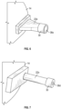
FIG. 2 is a perspective view of an embodiment of an insert for installation at a main body opening of a component; -
FIG. 3 is a perspective view of an embodiment of an insert for installation at a main body opening of a component; -
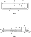
FIG. 4 is a plan view of installation of an embodiment of an insert at a main body opening of a component; -
FIG. 5 is a cross-sectional view of installation of an embodiment of an insert at a main body opening of a component; -
FIG. 6 is a perspective view of an embodiment of an insert installed to a main body of a component; and -
FIG. 7 is a perspective view of another embodiment of an insert installed to a main body of a component. - A detailed description of one or more embodiments of the disclosed apparatus and method are presented herein by way of exemplification and not limitation with reference to the Figures.
- Illustrated in
FIG. 1 is an embodiment of a component of a space vehicle or habitat, such as aphase separator 10. Thephase separator 10 includes amain body 12 with a plurality of main body openings formed therein. Thephase separator 10 is configured to separate liquid and gas components from a two-phase liquid/gas fluid. In some embodiments, the main body openings include afluid inlet 14, agas outlet 16 and aliquid outlet 18. Themain body 12 is connected to, for example, one or moreancillary components 20 via the main body openings. - To facilitate connection of the
main body 12 to theancillary components 20, aninsert 22, shown schematically in dashed lines inFIG. 1 for clarity, is installed to each of the respective main body openings of themain body 12. It is advantageous to provide themain body 12 with multiple main body openings, such asfluid inlet 14,gas outlet 16 andliquid outlet 18, which are identical in shape and size for ease of manufacturing of themain body 12 and thephase separator 10. As each of thefluid inlet 14, thegas outlet 16 and theliquid outlet 18, however, may have different flow requirements such as volume and pressure, and/or that these flow requirements may change when thephase separator 10 is connected to differentancillary components 20, theinserts 22 may be configured differently to meet the different flow requirements. - Referring now to
FIGs. 2 and 3 , an exemplary configuration of aninsert 22 is illustrated. Theinsert 22 includes abase 24 having attachment features, such asfastener openings 26, for securing theinset 22 to themain body 12 via one or more mechanical fasteners (not shown). Aport body 28 extends from thebase 24 to aport end 30. Theport end 30 may include afitting interface 32 to connect theinsert 22 to the selectedancillary component 20. Thebase 24 includes aback surface 34 which abuts and is secured to themain body 12 and afront surface 36 opposite theback surface 24, from which theport body 28 extends. Thebase 24 includes aninsert opening 38 extending through thebase 24 and theport body 28 to theport end 30. - Referring now to
FIGs. 4 and 5 , illustrated is a plan view and a cross-sectional view of theinsert 22 installed to the main body opening 40. Thebase 24 has abase perimeter 42 larger than the main body opening 40 so that theinsert 22 overlaps the main body opening 40 at an outermain body surface 44. Theinsert opening 38 has a first cross-sectional area that is smaller that a second cross-sectional area of the main body opening 40 to which theinsert 22 is installed. To account for the difference in these cross-sectional areas, thebase 24 of theinset 22 includes abase protrusion 46 that extends into the main body opening 40 thus blocking flow into theinsert 22. In some embodiments, such as shown, thebase protrusion 46 has a cross-sectional area sized such that thebase protrusion 46 blocks the main body opening 40 less the insert opening 38. In some embodiments, such as shown inFIG. 4 , the main body opening 40 has an oval or slit shape, and thebase protrusion 46 has a complimentary cross-sectional shape such that a protrusion outerperimetrical surface 48 directly abuts at least a portion of a main body openinginterior surface 50 for at least a portion of themain body opening 40. While an oval or slit shape of the main body opening 40 is shown inFIG. 4 and is described herein, one skilled in the art will readily appreciate that themain body openings 40 may have other shapes, such as circular or polygonal. Thebase protrusion 46 blocks the fluid flow to accomplish effectively altering the geometry of the main body opening 40 from the perspective of the fluid flow. - Referring again to
FIG. 5 , to reduce leakage between theinsert 22 and themain body 12, theinsert 22 includes a seal configuration extending around the main body opening 40 when theinsert 22 is installed to themain body 12. In some embodiments, the seal configuration includes a groove 52 (shown inFIG. 3 ) formed in thebase 24 and aseal element 54 installed in thegroove 52. When theinsert 22 is installed to themain body 12, theseal element 54 interfaces with the outermain body surface 44 to seal between theinset 22 and the outermain body surface 44. - Referring now to
FIG. 6 and 7 , the use of theinsert 22 described herein allows for easily changing between a relativelylarge insert opening 38a and port end 30 size shown inFIG. 6 and a relatively small insert opening 38b and port end 30 size by simply replacinginsert 22a with insert 22b, as inFIG. 7 . Such replacement is done without changing a size or configuration of the main body opening 40 or other features of themain body 12. This allows for the fabrication of commonmain body 12 andmain body openings 40, which are then adaptable for use with various inlet and outlet conditions by configuration of theinserts 22 installed therein. In some embodiments, theport end 30 may be laterally centered in theinsert 22 as shown inFIG. 6 , or alternatively may be offset to one lateral side of theinsert 22 as shown inFIG. 7 . - Varying flow conditions require different sizes of fluid ports to optimize flow, pressure loss, and configuration. The
insert 22 allows for adaptability to a wide range of operating conditions while reducing redesign and uniqueness of themain body 12. The flow passage including the main body opening 40 and theinsert opening 36 has a constant cross-sectional area from the main body12 to theport end 30 to reduce pressure change along the flow passage. - Further, since commonality is increased, cost and lead time of manufacturing of the
main body 12 and theinserts 22 may be reduced. The term "about" is intended to include the degree of error associated with measurement of the particular quantity based upon the equipment available at the time of filing the application. - The terminology used herein is for the purpose of describing particular embodiments only and is not intended to be limiting of the present disclosure. As used herein, the singular forms "a", "an" and "the" are intended to include the plural forms as well, unless the context clearly indicates otherwise. It will be further understood that the terms "comprises" and/or "comprising," when used in this specification, specify the presence of stated features, integers, steps, operations, elements, and/or components, but do not preclude the presence or addition of one or more other features, integers, steps, operations, element components, and/or groups thereof.
- While the present disclosure has been described with reference to an exemplary embodiment or embodiments, it will be understood by those skilled in the art that various changes may be made and equivalents may be substituted for elements thereof without departing from the scope of the present disclosure. In addition, many modifications may be made to adapt a particular situation or material to the teachings of the present disclosure without departing from the essential scope thereof. Therefore, it is intended that the present disclosure not be limited to the particular embodiment disclosed as the best mode contemplated for carrying out this present disclosure, but that the present disclosure will include all embodiments falling within the scope of the claims.
Claims (15)
- A component assembly for a space environment, comprising:a main body (12);a plurality of main body openings (40) in the main body, each main body opening having an identical cross-sectional shape;a plurality of inserts (22) installed to the main body at respective main body openings of the plurality of main body openings, each insert of the plurality of inserts defining a fluid port for a fluid flow to flow into the main body or out of the main body via the respective main body openings;wherein at least two fluid ports have a different cross-sectional configuration.
- The component assembly of claim 1, wherein each insert has an insert opening (38) having a constant cross-section from the main body opening to the fluid port.
- The component assembly of claim 1 or 2, wherein each insert includes an insert base (24) secured to the main body and a port body (28) extending from the insert base to the fluid port.
- The component assembly of claim 3, wherein the insert base (24) is secured to the main body (12) via one or more mechanical fasteners.
- The component assembly of any preceding claim, wherein the insert includes a seal to prevent leakage between the insert (22) and the main body (12).
- The component assembly of claim 5, wherein the seal extends from the insert and surrounds the respective main body opening.
- The component assembly of any preceding claim, wherein the insert includes an insert protrusion (46) extending into the respective main body opening to block a portion of a cross-sectional area of the main body opening.
- The component assembly of any preceding claim, wherein the plurality of main body openings (40) are oval or slot-shaped.
- The component assembly of any preceding claim, wherein the main body (12) is a phase separator and the plurality of main body openings are each an inlet or an outlet of the phase separator.
- A method of operating a component assembly for a space environment, comprising:providing a main body of the component assembly, the main body including a main body opening therein;installing a first insert to the main body opening, the first insert defining a first fluid port for a fluid flow to flow into the main body or out of the main body via the main body opening, the first fluid port having a first cross-sectional area;removing the first insert from the main body opening; andinstalling a second insert at the main body opening, the second insert defining a second fluid port for the fluid flow, the second fluid port having a second cross-sectional area different from the first cross-sectional area.
- The method of claim 10, wherein:the first insert includes a first insert protrusion extending into the main body opening to block a first portion of a cross-sectional area of the main body opening;the second insert includes a second insert protrusion extending into the main body opening to block a second portion of the cross-sectional area of the main body opening; andthe first portion is different from the second portion.
- The method of claim 10 or 11, wherein the first insert has a first insert opening having a constant cross-section from the main body opening to the first fluid port.
- The method of any of claims 10-12, further comprising securing the first insert to the main body a first insert base, and preferably wherein the first insert base is secured to the main body via one or more mechanical fasteners.
- The method of any of claims 10-13, further comprising installing a seal to prevent leakage between the first insert and the main body, and preferably wherein the seal extends from the first insert and surrounds the respective main body opening.
- The method of any of claims 10-14, wherein the main body opening is oval or slot-shaped.
Applications Claiming Priority (1)
| Application Number | Priority Date | Filing Date | Title |
|---|---|---|---|
| US17/412,756 US20230063146A1 (en) | 2021-08-26 | 2021-08-26 | Adjustable port size insert |
Publications (1)
| Publication Number | Publication Date |
|---|---|
| EP4140897A1 true EP4140897A1 (en) | 2023-03-01 |
Family
ID=82838910
Family Applications (1)
| Application Number | Title | Priority Date | Filing Date |
|---|---|---|---|
| EP22188728.4A Withdrawn EP4140897A1 (en) | 2021-08-26 | 2022-08-04 | Adjustable port size insert |
Country Status (3)
| Country | Link |
|---|---|
| US (1) | US20230063146A1 (en) |
| EP (1) | EP4140897A1 (en) |
| CN (1) | CN115723973A (en) |
Citations (5)
| Publication number | Priority date | Publication date | Assignee | Title |
|---|---|---|---|---|
| US20040250503A1 (en) * | 2003-06-10 | 2004-12-16 | Bigelow Robert T. | Multi-purpose beam |
| EP2775179A2 (en) * | 2013-03-08 | 2014-09-10 | Kohler Co. | Thermostatic fluid supply inverter valve |
| US20150197036A1 (en) * | 2014-01-15 | 2015-07-16 | United States Gypsum Company | Foam injection system with variable port inserts for slurry mixing and dispensing apparatus |
| US20180087683A1 (en) * | 2016-09-29 | 2018-03-29 | U.S.A. As Represented By The Administrator Of The National Aeronautics And Space Administration | Cooperative service valve for satellite media transfer |
| EP3859259A1 (en) * | 2020-02-03 | 2021-08-04 | Hamilton Sundstrand Corporation | Evaporator with grooved channels |
Family Cites Families (11)
| Publication number | Priority date | Publication date | Assignee | Title |
|---|---|---|---|---|
| US3494474A (en) * | 1968-12-26 | 1970-02-10 | Barnes Drill Co | Hydrocyclone separator with vortex starter |
| US3934990A (en) * | 1972-03-17 | 1976-01-27 | Stratoflex, Inc. | Air cooler and cleaner for compressed air |
| NL8420246A (en) * | 1983-10-06 | 1985-09-02 | Carroll Noel | CYCLONE SEPARATOR. |
| US5240115A (en) * | 1992-11-10 | 1993-08-31 | Beloit Technologies, Inc. | Field adjustable hydrocyclone |
| BRPI0803051B1 (en) * | 2008-06-30 | 2019-01-15 | Petróleo Brasileiro S/A - Petrobras | gas-solid suspension cyclonic separator and separation method |
| US8911635B2 (en) * | 2009-08-31 | 2014-12-16 | Petroleo Brasileiro S.A.—Petrobras | Hydrocyclone for the separation of fluids |
| US20140352934A1 (en) * | 2013-05-28 | 2014-12-04 | Hamilton Sundstrand Corporation | Plate heat exchanger |
| US10330131B2 (en) * | 2016-03-24 | 2019-06-25 | Schaeffler Technologies AG & Co. KG | Hydraulic fluid de-aeration device |
| US10758843B2 (en) * | 2017-12-11 | 2020-09-01 | Ford Global Technologies, Llc | Centrifugal fluid separator |
| US20190262841A1 (en) * | 2018-02-27 | 2019-08-29 | Certified Pressure Testing Llc | Sand separation system |
| US10953411B2 (en) * | 2018-06-26 | 2021-03-23 | Enercorp Sand Solutions Inc. | Modular cyclone |
-
2021
- 2021-08-26 US US17/412,756 patent/US20230063146A1/en not_active Abandoned
-
2022
- 2022-07-08 CN CN202210800933.3A patent/CN115723973A/en active Pending
- 2022-08-04 EP EP22188728.4A patent/EP4140897A1/en not_active Withdrawn
Patent Citations (5)
| Publication number | Priority date | Publication date | Assignee | Title |
|---|---|---|---|---|
| US20040250503A1 (en) * | 2003-06-10 | 2004-12-16 | Bigelow Robert T. | Multi-purpose beam |
| EP2775179A2 (en) * | 2013-03-08 | 2014-09-10 | Kohler Co. | Thermostatic fluid supply inverter valve |
| US20150197036A1 (en) * | 2014-01-15 | 2015-07-16 | United States Gypsum Company | Foam injection system with variable port inserts for slurry mixing and dispensing apparatus |
| US20180087683A1 (en) * | 2016-09-29 | 2018-03-29 | U.S.A. As Represented By The Administrator Of The National Aeronautics And Space Administration | Cooperative service valve for satellite media transfer |
| EP3859259A1 (en) * | 2020-02-03 | 2021-08-04 | Hamilton Sundstrand Corporation | Evaporator with grooved channels |
Also Published As
| Publication number | Publication date |
|---|---|
| US20230063146A1 (en) | 2023-03-02 |
| CN115723973A (en) | 2023-03-03 |
Similar Documents
| Publication | Publication Date | Title |
|---|---|---|
| EP0223569B1 (en) | Filtering system | |
| US4983102A (en) | Self-enclosed filter pumping system | |
| US8066871B2 (en) | Filtration system incorporating modular one-piece end caps | |
| EP0937868A1 (en) | Oil filter fixing structure | |
| MX2008014931A (en) | Tri-flow filter element with venting. | |
| KR100297260B1 (en) | Liquid tank | |
| EP1938881A1 (en) | Filtration device | |
| EP3065963A1 (en) | Liquid vapor separator drain valve | |
| EP1042044A1 (en) | Filter assembly | |
| US20230063146A1 (en) | Adjustable port size insert | |
| US7278448B2 (en) | Rotary ball valve assembly | |
| EP0686794B1 (en) | A housing for diverter valve | |
| CN105764586A (en) | Filter element and filter system with bypass filter element | |
| CN100562650C (en) | Support structure and method for filter medium in filter of engine or transmission | |
| US20020106287A1 (en) | Air compressor system and an air/oil cast separator tank for the same | |
| KR100804862B1 (en) | Module integrating filtration gasket and filtration installed in such gasket | |
| US20220266178A1 (en) | Fluid Filter for a Motor Vehicle and Filter Cartridge for a Fluid Filter | |
| EP3292901A1 (en) | Drainage system for a fluid filter | |
| CN112855838A (en) | Separating element for hydraulic vibration-proof module and hydraulic vibration-proof module equipped with same | |
| JP4282637B2 (en) | Scroll compressor | |
| EP4142910A1 (en) | Modular filter manifold | |
| US11491427B2 (en) | Adaptor plug for a spin-on filter | |
| US6959563B2 (en) | Insert for use in a refrigerant receiver | |
| CN115126569A (en) | Oil separator for internal combustion engine | |
| US20240001898A1 (en) | Filter for a brake fluid reservoir |
Legal Events
| Date | Code | Title | Description |
|---|---|---|---|
| PUAI | Public reference made under article 153(3) epc to a published international application that has entered the european phase |
Free format text: ORIGINAL CODE: 0009012 |
|
| STAA | Information on the status of an ep patent application or granted ep patent |
Free format text: STATUS: THE APPLICATION HAS BEEN PUBLISHED |
|
| AK | Designated contracting states |
Kind code of ref document: A1 Designated state(s): AL AT BE BG CH CY CZ DE DK EE ES FI FR GB GR HR HU IE IS IT LI LT LU LV MC MK MT NL NO PL PT RO RS SE SI SK SM TR |
|
| STAA | Information on the status of an ep patent application or granted ep patent |
Free format text: STATUS: REQUEST FOR EXAMINATION WAS MADE |
|
| 17P | Request for examination filed |
Effective date: 20230830 |
|
| RBV | Designated contracting states (corrected) |
Designated state(s): AL AT BE BG CH CY CZ DE DK EE ES FI FR GB GR HR HU IE IS IT LI LT LU LV MC MK MT NL NO PL PT RO RS SE SI SK SM TR |
|
| STAA | Information on the status of an ep patent application or granted ep patent |
Free format text: STATUS: EXAMINATION IS IN PROGRESS |
|
| 17Q | First examination report despatched |
Effective date: 20240625 |
|
| STAA | Information on the status of an ep patent application or granted ep patent |
Free format text: STATUS: THE APPLICATION IS DEEMED TO BE WITHDRAWN |
|
| 18D | Application deemed to be withdrawn |
Effective date: 20250301 |