EP4140893A1 - Integrated ice protection with prognostics and health management - Google Patents
Integrated ice protection with prognostics and health management Download PDFInfo
- Publication number
- EP4140893A1 EP4140893A1 EP22188835.7A EP22188835A EP4140893A1 EP 4140893 A1 EP4140893 A1 EP 4140893A1 EP 22188835 A EP22188835 A EP 22188835A EP 4140893 A1 EP4140893 A1 EP 4140893A1
- Authority
- EP
- European Patent Office
- Prior art keywords
- sensor
- fiber optic
- equipment
- sensors
- reading
- Prior art date
- Legal status (The legal status is an assumption and is not a legal conclusion. Google has not performed a legal analysis and makes no representation as to the accuracy of the status listed.)
- Granted
Links
Images


Classifications
-
- B—PERFORMING OPERATIONS; TRANSPORTING
- B64—AIRCRAFT; AVIATION; COSMONAUTICS
- B64D—EQUIPMENT FOR FITTING IN OR TO AIRCRAFT; FLIGHT SUITS; PARACHUTES; ARRANGEMENT OR MOUNTING OF POWER PLANTS OR PROPULSION TRANSMISSIONS IN AIRCRAFT
- B64D15/00—De-icing or preventing icing on exterior surfaces of aircraft
- B64D15/20—Means for detecting icing or initiating de-icing
-
- B—PERFORMING OPERATIONS; TRANSPORTING
- B64—AIRCRAFT; AVIATION; COSMONAUTICS
- B64D—EQUIPMENT FOR FITTING IN OR TO AIRCRAFT; FLIGHT SUITS; PARACHUTES; ARRANGEMENT OR MOUNTING OF POWER PLANTS OR PROPULSION TRANSMISSIONS IN AIRCRAFT
- B64D45/00—Aircraft indicators or protectors not otherwise provided for
-
- B—PERFORMING OPERATIONS; TRANSPORTING
- B65—CONVEYING; PACKING; STORING; HANDLING THIN OR FILAMENTARY MATERIAL
- B65D—CONTAINERS FOR STORAGE OR TRANSPORT OF ARTICLES OR MATERIALS, e.g. BAGS, BARRELS, BOTTLES, BOXES, CANS, CARTONS, CRATES, DRUMS, JARS, TANKS, HOPPERS, FORWARDING CONTAINERS; ACCESSORIES, CLOSURES, OR FITTINGS THEREFOR; PACKAGING ELEMENTS; PACKAGES
- B65D43/00—Lids or covers for rigid or semi-rigid containers
-
- G—PHYSICS
- G01—MEASURING; TESTING
- G01D—MEASURING NOT SPECIALLY ADAPTED FOR A SPECIFIC VARIABLE; ARRANGEMENTS FOR MEASURING TWO OR MORE VARIABLES NOT COVERED IN A SINGLE OTHER SUBCLASS; TARIFF METERING APPARATUS; MEASURING OR TESTING NOT OTHERWISE PROVIDED FOR
- G01D21/00—Measuring or testing not otherwise provided for
-
- G—PHYSICS
- G01—MEASURING; TESTING
- G01D—MEASURING NOT SPECIALLY ADAPTED FOR A SPECIFIC VARIABLE; ARRANGEMENTS FOR MEASURING TWO OR MORE VARIABLES NOT COVERED IN A SINGLE OTHER SUBCLASS; TARIFF METERING APPARATUS; MEASURING OR TESTING NOT OTHERWISE PROVIDED FOR
- G01D9/00—Recording measured values
- G01D9/28—Producing one or more recordings, each recording being of the values of two or more different variables
-
- G—PHYSICS
- G01—MEASURING; TESTING
- G01K—MEASURING TEMPERATURE; MEASURING QUANTITY OF HEAT; THERMALLY-SENSITIVE ELEMENTS NOT OTHERWISE PROVIDED FOR
- G01K11/00—Measuring temperature based upon physical or chemical changes not covered by groups G01K3/00, G01K5/00, G01K7/00 or G01K9/00
- G01K11/32—Measuring temperature based upon physical or chemical changes not covered by groups G01K3/00, G01K5/00, G01K7/00 or G01K9/00 using changes in transmittance, scattering or luminescence in optical fibres
- G01K11/3206—Measuring temperature based upon physical or chemical changes not covered by groups G01K3/00, G01K5/00, G01K7/00 or G01K9/00 using changes in transmittance, scattering or luminescence in optical fibres at discrete locations in the fibre, e.g. using Bragg scattering
-
- G—PHYSICS
- G01—MEASURING; TESTING
- G01L—MEASURING FORCE, STRESS, TORQUE, WORK, MECHANICAL POWER, MECHANICAL EFFICIENCY, OR FLUID PRESSURE
- G01L1/00—Measuring force or stress, in general
- G01L1/24—Measuring force or stress, in general by measuring variations of optical properties of material when it is stressed, e.g. by photoelastic stress analysis using infrared, visible light, ultraviolet
- G01L1/242—Measuring force or stress, in general by measuring variations of optical properties of material when it is stressed, e.g. by photoelastic stress analysis using infrared, visible light, ultraviolet the material being an optical fibre
- G01L1/246—Measuring force or stress, in general by measuring variations of optical properties of material when it is stressed, e.g. by photoelastic stress analysis using infrared, visible light, ultraviolet the material being an optical fibre using integrated gratings, e.g. Bragg gratings
-
- G—PHYSICS
- G01—MEASURING; TESTING
- G01M—TESTING STATIC OR DYNAMIC BALANCE OF MACHINES OR STRUCTURES; TESTING OF STRUCTURES OR APPARATUS, NOT OTHERWISE PROVIDED FOR
- G01M5/00—Investigating the elasticity of structures, e.g. deflection of bridges or air-craft wings
- G01M5/0016—Investigating the elasticity of structures, e.g. deflection of bridges or air-craft wings of aircraft wings or blades
-
- G—PHYSICS
- G01—MEASURING; TESTING
- G01M—TESTING STATIC OR DYNAMIC BALANCE OF MACHINES OR STRUCTURES; TESTING OF STRUCTURES OR APPARATUS, NOT OTHERWISE PROVIDED FOR
- G01M5/00—Investigating the elasticity of structures, e.g. deflection of bridges or air-craft wings
- G01M5/0091—Investigating the elasticity of structures, e.g. deflection of bridges or air-craft wings by using electromagnetic excitation or detection
-
- G—PHYSICS
- G02—OPTICS
- G02B—OPTICAL ELEMENTS, SYSTEMS OR APPARATUS
- G02B6/00—Light guides; Structural details of arrangements comprising light guides and other optical elements, e.g. couplings
- G02B6/10—Light guides; Structural details of arrangements comprising light guides and other optical elements, e.g. couplings of the optical waveguide type
- G02B6/12—Light guides; Structural details of arrangements comprising light guides and other optical elements, e.g. couplings of the optical waveguide type of the integrated circuit kind
-
- B—PERFORMING OPERATIONS; TRANSPORTING
- B64—AIRCRAFT; AVIATION; COSMONAUTICS
- B64D—EQUIPMENT FOR FITTING IN OR TO AIRCRAFT; FLIGHT SUITS; PARACHUTES; ARRANGEMENT OR MOUNTING OF POWER PLANTS OR PROPULSION TRANSMISSIONS IN AIRCRAFT
- B64D45/00—Aircraft indicators or protectors not otherwise provided for
- B64D2045/0085—Devices for aircraft health monitoring, e.g. monitoring flutter or vibration
-
- G—PHYSICS
- G01—MEASURING; TESTING
- G01D—MEASURING NOT SPECIALLY ADAPTED FOR A SPECIFIC VARIABLE; ARRANGEMENTS FOR MEASURING TWO OR MORE VARIABLES NOT COVERED IN A SINGLE OTHER SUBCLASS; TARIFF METERING APPARATUS; MEASURING OR TESTING NOT OTHERWISE PROVIDED FOR
- G01D2207/00—Indexing scheme relating to details of indicating measuring values
- G01D2207/10—Displays which are primarily used in aircraft or display aircraft-specific information
-
- G—PHYSICS
- G01—MEASURING; TESTING
- G01D—MEASURING NOT SPECIALLY ADAPTED FOR A SPECIFIC VARIABLE; ARRANGEMENTS FOR MEASURING TWO OR MORE VARIABLES NOT COVERED IN A SINGLE OTHER SUBCLASS; TARIFF METERING APPARATUS; MEASURING OR TESTING NOT OTHERWISE PROVIDED FOR
- G01D5/00—Mechanical means for transferring the output of a sensing member; Means for converting the output of a sensing member to another variable where the form or nature of the sensing member does not constrain the means for converting; Transducers not specially adapted for a specific variable
- G01D5/26—Mechanical means for transferring the output of a sensing member; Means for converting the output of a sensing member to another variable where the form or nature of the sensing member does not constrain the means for converting; Transducers not specially adapted for a specific variable characterised by optical transfer means, i.e. using infrared, visible, or ultraviolet light
- G01D5/268—Mechanical means for transferring the output of a sensing member; Means for converting the output of a sensing member to another variable where the form or nature of the sensing member does not constrain the means for converting; Transducers not specially adapted for a specific variable characterised by optical transfer means, i.e. using infrared, visible, or ultraviolet light using optical fibres
-
- G—PHYSICS
- G01—MEASURING; TESTING
- G01D—MEASURING NOT SPECIALLY ADAPTED FOR A SPECIFIC VARIABLE; ARRANGEMENTS FOR MEASURING TWO OR MORE VARIABLES NOT COVERED IN A SINGLE OTHER SUBCLASS; TARIFF METERING APPARATUS; MEASURING OR TESTING NOT OTHERWISE PROVIDED FOR
- G01D5/00—Mechanical means for transferring the output of a sensing member; Means for converting the output of a sensing member to another variable where the form or nature of the sensing member does not constrain the means for converting; Transducers not specially adapted for a specific variable
- G01D5/26—Mechanical means for transferring the output of a sensing member; Means for converting the output of a sensing member to another variable where the form or nature of the sensing member does not constrain the means for converting; Transducers not specially adapted for a specific variable characterised by optical transfer means, i.e. using infrared, visible, or ultraviolet light
- G01D5/32—Mechanical means for transferring the output of a sensing member; Means for converting the output of a sensing member to another variable where the form or nature of the sensing member does not constrain the means for converting; Transducers not specially adapted for a specific variable characterised by optical transfer means, i.e. using infrared, visible, or ultraviolet light with attenuation or whole or partial obturation of beams of light
- G01D5/34—Mechanical means for transferring the output of a sensing member; Means for converting the output of a sensing member to another variable where the form or nature of the sensing member does not constrain the means for converting; Transducers not specially adapted for a specific variable characterised by optical transfer means, i.e. using infrared, visible, or ultraviolet light with attenuation or whole or partial obturation of beams of light the beams of light being detected by photocells
- G01D5/353—Mechanical means for transferring the output of a sensing member; Means for converting the output of a sensing member to another variable where the form or nature of the sensing member does not constrain the means for converting; Transducers not specially adapted for a specific variable characterised by optical transfer means, i.e. using infrared, visible, or ultraviolet light with attenuation or whole or partial obturation of beams of light the beams of light being detected by photocells influencing the transmission properties of an optical fibre
- G01D5/35306—Mechanical means for transferring the output of a sensing member; Means for converting the output of a sensing member to another variable where the form or nature of the sensing member does not constrain the means for converting; Transducers not specially adapted for a specific variable characterised by optical transfer means, i.e. using infrared, visible, or ultraviolet light with attenuation or whole or partial obturation of beams of light the beams of light being detected by photocells influencing the transmission properties of an optical fibre using an interferometer arrangement
- G01D5/35309—Mechanical means for transferring the output of a sensing member; Means for converting the output of a sensing member to another variable where the form or nature of the sensing member does not constrain the means for converting; Transducers not specially adapted for a specific variable characterised by optical transfer means, i.e. using infrared, visible, or ultraviolet light with attenuation or whole or partial obturation of beams of light the beams of light being detected by photocells influencing the transmission properties of an optical fibre using an interferometer arrangement using multiple waves interferometer
- G01D5/35316—Mechanical means for transferring the output of a sensing member; Means for converting the output of a sensing member to another variable where the form or nature of the sensing member does not constrain the means for converting; Transducers not specially adapted for a specific variable characterised by optical transfer means, i.e. using infrared, visible, or ultraviolet light with attenuation or whole or partial obturation of beams of light the beams of light being detected by photocells influencing the transmission properties of an optical fibre using an interferometer arrangement using multiple waves interferometer using a Bragg gratings
-
- G—PHYSICS
- G01—MEASURING; TESTING
- G01D—MEASURING NOT SPECIALLY ADAPTED FOR A SPECIFIC VARIABLE; ARRANGEMENTS FOR MEASURING TWO OR MORE VARIABLES NOT COVERED IN A SINGLE OTHER SUBCLASS; TARIFF METERING APPARATUS; MEASURING OR TESTING NOT OTHERWISE PROVIDED FOR
- G01D5/00—Mechanical means for transferring the output of a sensing member; Means for converting the output of a sensing member to another variable where the form or nature of the sensing member does not constrain the means for converting; Transducers not specially adapted for a specific variable
- G01D5/26—Mechanical means for transferring the output of a sensing member; Means for converting the output of a sensing member to another variable where the form or nature of the sensing member does not constrain the means for converting; Transducers not specially adapted for a specific variable characterised by optical transfer means, i.e. using infrared, visible, or ultraviolet light
- G01D5/32—Mechanical means for transferring the output of a sensing member; Means for converting the output of a sensing member to another variable where the form or nature of the sensing member does not constrain the means for converting; Transducers not specially adapted for a specific variable characterised by optical transfer means, i.e. using infrared, visible, or ultraviolet light with attenuation or whole or partial obturation of beams of light
- G01D5/34—Mechanical means for transferring the output of a sensing member; Means for converting the output of a sensing member to another variable where the form or nature of the sensing member does not constrain the means for converting; Transducers not specially adapted for a specific variable characterised by optical transfer means, i.e. using infrared, visible, or ultraviolet light with attenuation or whole or partial obturation of beams of light the beams of light being detected by photocells
- G01D5/353—Mechanical means for transferring the output of a sensing member; Means for converting the output of a sensing member to another variable where the form or nature of the sensing member does not constrain the means for converting; Transducers not specially adapted for a specific variable characterised by optical transfer means, i.e. using infrared, visible, or ultraviolet light with attenuation or whole or partial obturation of beams of light the beams of light being detected by photocells influencing the transmission properties of an optical fibre
- G01D5/3537—Optical fibre sensor using a particular arrangement of the optical fibre itself
- G01D5/35374—Particular layout of the fiber
-
- G—PHYSICS
- G01—MEASURING; TESTING
- G01K—MEASURING TEMPERATURE; MEASURING QUANTITY OF HEAT; THERMALLY-SENSITIVE ELEMENTS NOT OTHERWISE PROVIDED FOR
- G01K2213/00—Temperature mapping
-
- G—PHYSICS
- G02—OPTICS
- G02B—OPTICAL ELEMENTS, SYSTEMS OR APPARATUS
- G02B6/00—Light guides; Structural details of arrangements comprising light guides and other optical elements, e.g. couplings
- G02B6/10—Light guides; Structural details of arrangements comprising light guides and other optical elements, e.g. couplings of the optical waveguide type
- G02B6/12—Light guides; Structural details of arrangements comprising light guides and other optical elements, e.g. couplings of the optical waveguide type of the integrated circuit kind
- G02B2006/12133—Functions
- G02B2006/12138—Sensor
Definitions
- the present invention relates to ice protection systems, and more specifically, to integrated ice protection with prognostics and health management using fiber optic sensors.
- Aircraft can be exposed to weather conditions that allow ice to form on its surfaces. Ice can be formed on the surfaces of the aircraft such as the windscreen, wings, tail, and air intake components before or during flight. The build up of ice can lead to adverse operation such as blocking needed engine airflow or inhibiting the operation of the wings or other components. In addition, damage to other components and the safety of the aircraft and passengers can result. Aircraft equipped with heating components can include electric heaters to protect the aircraft. There may be a need to ensure the proper operation of the heating components over the life of the aircraft.
- a method for operating an integrated ice protection with prognostics and health management can include reading a signal from each sensor of an array of sensors installed on a surface of a structure or equipment, wherein each sensor is a fiber optic sensor, and generating a map based on reading the signal from each sensor, wherein the map monitors a condition of the surface detected by each sensor.
- the method can also include determining at least one of an abnormal condition or a failure based at least in part on reading the signal from each sensor, and performing at least one of adjusting power control for the structure or equipment or communicating the abnormal condition or failure of the structure or equipment.
- further embodiments include using a map that is a temperature map.
- further embodiments include reading a signal that is transmitted over a fiber optic cable.
- further embodiments include using a plurality of sensors that is coupled to each fiber optic cable.
- further embodiments include arranging each fiber optic cable to monitor a zone of a structure.
- further embodiments include using a map that indicates a sensor type for each sensor.
- further embodiments include using sensor types such as temperature sensors and strain sensors.
- further embodiments include determining the health of the equipment by comparing historical readings to real-time readings for the equipment.
- an integrated ice protection with prognostics and health management using fiber optic sensors includes a sensor array and a controller coupled to the sensor array.
- the controller can be to reading signals from each sensor of the sensor array installed on a surface of a structure or equipment, wherein each sensor is a fiber optic sensor, and generating a map based on reading the signal from each sensor, wherein the map monitors the surface and a condition of the surface detected by each sensor.
- the controller can also include determining at least one of an abnormal condition or a failure based at least in part on reading the signal from each sensor, and performing at least one of adjusting power control for the structure or equipment or communicating the abnormal condition or failure of the structure or equipment.
- further embodiments include using a map that is a temperature map.
- further embodiments include reading a signal that is transmitted over a fiber optic cable.
- further embodiments include using a plurality of sensors that is coupled to each fiber optic cable.
- further embodiments include arranging each fiber optic cable to monitor a zone of a structure.
- further embodiments include using a map that indicates a sensor type for each sensor.
- further embodiments include using sensor types such as temperature sensors and strain sensors.
- further embodiments include determining the health of the equipment by comparing historical readings to real-time readings for the equipment.
- the techniques described herein integrate an array of fiber optic sensors that are arranged to cover deicing and heating components and the surrounding area in order to detect and map the surface temperature where ice protection is required.
- the array of fiber optic sensors can be also installed beyond the ice protected area extending its area of monitoring for detecting ice runback or ice conditions beyond of the icing protection envelope.
- the fiber optic sensors can also assist in power management of the ice protection system by monitoring real-time impingement limits of the protected surface.
- the ice protection system can be operated to adjust heater ON/OFF times or determine which zones are activated based on this feedback. These adjustments can lead to minimizing the ice protection energy usage resulting in fuel savings for conventional aircraft or extended battery life for electric aircraft.
- the array of fiber optic sensors can be installed in any location of the structure.
- the array of sensor is not limited to temperature, the sensing elements may include strain gauges for monitoring stress as well as structural or heater failure.
- the integration of electrical ice protection and PHM with array of fiber optic sensor can be installed in composite or metallic
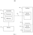
- FIG. 1 depicts a system 100 in accordance with one or more embodiments of the disclosure.
- the system 100 can include a controller 102.
- the controller 102 includes a processor 104 and a memory 106 to carry out the operations for the integrated ice protection system with prognostics and health management. It can be appreciated the controller 102 can include other components or modules and is not limited by the components shown in FIG. 1 .
- the processor 102 can include a processor 102 of a general-purpose computer, special purpose computer, or other programmable data processing apparatus configured to execute instruction via the processor of the computer or other programmable data processing apparatus.
- the controller 102 is configured to monitor the surface 108 of a structure, such as an aircraft wing.
- the fiber optic sensors can be coupled to the controller over a plurality of fiber optic cables 112.
- the temperature of the surface 108 can be monitored using fiber optic sensors forming a sensor network 110.
- strain gauges can be used to monitor the stress or tension experienced on the surface 108.
- the fiber optic sensors can receive a light signal that can be converted to a digital signal either in the sensing element or at a remote processing element in the controller.
- the fiber optic sensors do not require electric power for operation and the fiber optic sensors are not vulnerable to electromagnetic interference. This allows fiber optic sensors to be used in remote spaces without having excess wiring to power the fiber optic sensors.
- the memory 106 of the controller 102 can store the address of each of the sensors and related the address with a position/location of the sensor on the surface 108 and/or structure. Also, the memory 106 of the controller 102 can be configured with alarm limits that can be used to trigger an alert that can be transmitted to one or more connected devices.
- the sensor network 110 can be arranged in a protected zone 114 of the surface 108 and non-protected zone 116.
- the protected zone 114 the fiber optic sensors can be arranged to monitor an area that is within proximity to a heater (not shown) for protecting the aircraft wing, and the non-protected zone 116 the fiber optic sensors can be arranged to monitor the runback of the melted ice.
- the sensor network 110 can be arranged on the surface of aircraft equipment such as a heat generating equipment for protecting the aircraft and is not limited to the aircraft wing.
- the heating components of the aircraft can include an electric heater that converts electric energy to heat energy using a heating element.
- Other heating components can include embedding heating wires on various surfaces of the aircraft.
- the heating components can include metal heating elements formed of stainless steel, copper, wire, cloth, or other electrically conductive mediums.
- the system 100 can include a device 118 for communicating with the controller 102.
- the device 118 can include but is not limited to a computer, laptop, user device, aircraft avionics system, or smart device.
- the controller 102 can be operated to communicate or transmit the abnormal readings and/or failure conditions of the surface of the structure or equipment that is being monitored.
- the abnormal readings can be determined based on comparing the current readings to normal or historical readings.
- the failure conditions can be determined by comparing the current sensor readings to pre-determined or configurable thresholds to determine whether a failure condition exists. For example, real-time temperature readings that exceed a configurable threshold temperature can indicate a failure while increased temperature readings over normal or historical readings can indicate a trend toward the failure.
- FIG. 2 an example arrangement of fiber optic-based sensors positioned on a surface of a portion of an aircraft wing 202 is shown.
- a controller such as controller 102 is not shown in FIG. 2
- the fiber optic cables 208 are coupled to a controller to receive the signals.
- FIG. 2 depicts a plurality of temperature sensors 204 and a plurality strain gauge sensors 206.
- Each fiber optic cable 208 can include both types of sensors 204, 206 which reduces the amount of additional wires that are needed to install the different type of sensors.
- the plurality of sensors 204, 206 is coupled to each fiber optic cable 208, and the individual readings from sensors 204, 206 on the same fiber optic cable 208 can be processed in by the controller 102 in a variety of ways.
- the controller 102 can process each signal from corresponding sensors 204, 206 using a known time delay or wavelength.
- Each of the sensors 204, 206 can be associated with a particular location of the aircraft wing 202 for mapping.
- FIG. 2 illustrates a fixed number of sensors, however, it should be understood that any number of sensors and placement of the sensors can be used.
- the arrangement of fiber optic-based sensors is on a surface of an aircraft wing 202, it can be appreciated the sensors can be placed directly on the equipment for monitoring.
- the sensors 204, 206 can be arranged in a plurality of zones 210-218 of the aircraft can be used for monitoring the various zones.
- FIG. 3 depicts a flowchart of a method 300 for performing integrated ice protection solution with prognostics and health management in accordance with one or more embodiments of the disclosure.
- the method 300 can be implemented in the system such as the system 100 shown in FIG. 1 or other similar type of system.
- the method 300 begins at block 302 and continues to block 304 which provides for reading signals from each sensor of an array of sensors installed on a surface of a structure, wherein each sensor is a fiber optic sensor.
- the fiber optic sensors can include temperature sensors and strain sensors (strain gauges).
- Block 306 generates a map based on reading the signal from each sensor, wherein the map monitors a condition of the surface detected by each sensor.
- the controller 102 is configured to internally update the power activation control for the structure or equipment based on sensor feedback or detects abnormal conditions based on signal readings from each sensor.
- Block 308 determines at least one of an abnormal condition or a failure based at least in part on reading the signal from each sensor.
- Block 310 performs at least one of adjusting power control for the structure or equipment or communicating the abnormal condition or failure of the structure or equipment. The method 300 ends at block 311.
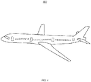
- FIG. 4 depicts an example of an aircraft that is monitored in accordance with one or more embodiments of the disclosure. Although an aircraft is shown, the techniques described herein can be applied to other vehicles and is not limited by the illustration shown in FIG. 4 .
- the technical effects and benefits include generating a temperature map using readings from fiber optic sensors arranged on a surface.
- the arrangement can expose cold spots during deicing of an aircraft.
- the technical effects and benefits also include obtaining real-time diagnostic features to improve power management of the system and for performing health management of the aircraft surfaces and equipment.
Landscapes
- Physics & Mathematics (AREA)
- Engineering & Computer Science (AREA)
- General Physics & Mathematics (AREA)
- Aviation & Aerospace Engineering (AREA)
- Microelectronics & Electronic Packaging (AREA)
- Optics & Photonics (AREA)
- Mechanical Engineering (AREA)
- Electromagnetism (AREA)
- Measuring Temperature Or Quantity Of Heat (AREA)
- Length Measuring Devices By Optical Means (AREA)
- Testing Or Calibration Of Command Recording Devices (AREA)
Abstract
Description
- The present invention relates to ice protection systems, and more specifically, to integrated ice protection with prognostics and health management using fiber optic sensors.
- Aircraft can be exposed to weather conditions that allow ice to form on its surfaces. Ice can be formed on the surfaces of the aircraft such as the windscreen, wings, tail, and air intake components before or during flight. The build up of ice can lead to adverse operation such as blocking needed engine airflow or inhibiting the operation of the wings or other components. In addition, damage to other components and the safety of the aircraft and passengers can result. Aircraft equipped with heating components can include electric heaters to protect the aircraft. There may be a need to ensure the proper operation of the heating components over the life of the aircraft.
- According to an embodiment, a method for operating an integrated ice protection with prognostics and health management is provided. The method can include reading a signal from each sensor of an array of sensors installed on a surface of a structure or equipment, wherein each sensor is a fiber optic sensor, and generating a map based on reading the signal from each sensor, wherein the map monitors a condition of the surface detected by each sensor. The method can also include determining at least one of an abnormal condition or a failure based at least in part on reading the signal from each sensor, and performing at least one of adjusting power control for the structure or equipment or communicating the abnormal condition or failure of the structure or equipment.
- In addition to one or more of the features described herein, or as an alternative, further embodiments include using a map that is a temperature map.
- In addition to one or more of the features described herein, or as an alternative, further embodiments include reading a signal that is transmitted over a fiber optic cable.
- In addition to one or more of the features described herein, or as an alternative, further embodiments include using a plurality of sensors that is coupled to each fiber optic cable.
- In addition to one or more of the features described herein, or as an alternative, further embodiments include arranging each fiber optic cable to monitor a zone of a structure.
- In addition to one or more of the features described herein, or as an alternative, further embodiments include using a map that indicates a sensor type for each sensor.
- In addition to one or more of the features described herein, or as an alternative, further embodiments include using sensor types such as temperature sensors and strain sensors.
- In addition to one or more of the features described herein, or as an alternative, further embodiments include determining the health of the equipment by comparing historical readings to real-time readings for the equipment.
- According to an embodiment, an integrated ice protection with prognostics and health management using fiber optic sensors is provided. The system includes a sensor array and a controller coupled to the sensor array. The controller can be to reading signals from each sensor of the sensor array installed on a surface of a structure or equipment, wherein each sensor is a fiber optic sensor, and generating a map based on reading the signal from each sensor, wherein the map monitors the surface and a condition of the surface detected by each sensor. The controller can also include determining at least one of an abnormal condition or a failure based at least in part on reading the signal from each sensor, and performing at least one of adjusting power control for the structure or equipment or communicating the abnormal condition or failure of the structure or equipment.
- In addition to one or more of the features described herein, or as an alternative, further embodiments include using a map that is a temperature map.
- In addition to one or more of the features described herein, or as an alternative, further embodiments include reading a signal that is transmitted over a fiber optic cable.
- In addition to one or more of the features described herein, or as an alternative, further embodiments include using a plurality of sensors that is coupled to each fiber optic cable.
- In addition to one or more of the features described herein, or as an alternative, further embodiments include arranging each fiber optic cable to monitor a zone of a structure.
- In addition to one or more of the features described herein, or as an alternative, further embodiments include using a map that indicates a sensor type for each sensor.
- In addition to one or more of the features described herein, or as an alternative, further embodiments include using sensor types such as temperature sensors and strain sensors.
- In addition to one or more of the features described herein, or as an alternative, further embodiments include determining the health of the equipment by comparing historical readings to real-time readings for the equipment.
- Technical effects of embodiments of the present disclosure include generating and displaying a map representing the temperature readings obtained from the plurality of sensors.
- The foregoing features and elements may be combined in various combinations without exclusivity, unless expressly indicated otherwise. These features and elements as well as the operation thereof will become more apparent in light of the following description and the accompanying drawings. It should be understood, however, that the following description and drawings are intended to be illustrative and explanatory in nature and non-limiting.
- The following descriptions should not be considered limiting in any way. With reference to the accompanying drawings, like elements are numbered alike:
-
FIG. 1 depicts a block diagram of a system in accordance with one or more embodiment of the disclosure -
FIG. 2 depicts an example configuration of an arrangement of sensors on a surface in accordance with one or more embodiments of the disclosure; -
FIG. 3 depicts a flowchart of a method for generating a temperature map in accordance with one or more embodiments of the disclosure; and -
FIG. 4 depicts an example aircraft upon which the arrangement of sensors in accordance with one or more embodiments of the disclosure. - Current ice protection systems do not provide diagnostic and prognostic health monitoring management for the condition and performance of the heater components and surrounding structure. The lack of feedback indicating the performance and health of the system can lead to potential unknown areas of concern before/during/after operation which can increase the system operational cost. Also, the lack of real-time temperature mapping of the structure and heater elements hide cold or hot spots in the system causing potential hazardous for the aircraft, engine and crew during flight in icing conditions.
- Conventional temperature mapping using current technologies such as resistance temperature detectors (RTDs) require numerous sensors and is limited because they can only obtain point measurements. Point measurements are limited to a particular location. This can lead to a decrease in system reliability from the many added sensors and extra electrical connections. Prognostic health management (PHM) temperature mapping with fiber optic sensors do not require as many electrical connections thus decreasing the impact to improve system reliability.
- The techniques described herein integrate an array of fiber optic sensors that are arranged to cover deicing and heating components and the surrounding area in order to detect and map the surface temperature where ice protection is required. The array of fiber optic sensors can be also installed beyond the ice protected area extending its area of monitoring for detecting ice runback or ice conditions beyond of the icing protection envelope. The fiber optic sensors can also assist in power management of the ice protection system by monitoring real-time impingement limits of the protected surface. The ice protection system can be operated to adjust heater ON/OFF times or determine which zones are activated based on this feedback. These adjustments can lead to minimizing the ice protection energy usage resulting in fuel savings for conventional aircraft or extended battery life for electric aircraft. The array of fiber optic sensors can be installed in any location of the structure. The array of sensor is not limited to temperature, the sensing elements may include strain gauges for monitoring stress as well as structural or heater failure. The integration of electrical ice protection and PHM with array of fiber optic sensor can be installed in composite or metallic components.
-
FIG. 1 depicts asystem 100 in accordance with one or more embodiments of the disclosure. Thesystem 100 can include acontroller 102. Thecontroller 102 includes aprocessor 104 and amemory 106 to carry out the operations for the integrated ice protection system with prognostics and health management. It can be appreciated thecontroller 102 can include other components or modules and is not limited by the components shown inFIG. 1 . In one or more embodiments of the disclosure, theprocessor 102 can include aprocessor 102 of a general-purpose computer, special purpose computer, or other programmable data processing apparatus configured to execute instruction via the processor of the computer or other programmable data processing apparatus. - The
controller 102 is configured to monitor thesurface 108 of a structure, such as an aircraft wing. The fiber optic sensors can be coupled to the controller over a plurality of fiberoptic cables 112. The temperature of thesurface 108 can be monitored using fiber optic sensors forming asensor network 110. In addition, strain gauges can be used to monitor the stress or tension experienced on thesurface 108. The fiber optic sensors can receive a light signal that can be converted to a digital signal either in the sensing element or at a remote processing element in the controller. Also, the fiber optic sensors do not require electric power for operation and the fiber optic sensors are not vulnerable to electromagnetic interference. This allows fiber optic sensors to be used in remote spaces without having excess wiring to power the fiber optic sensors. - In one or more embodiments, during installation of the sensors the
memory 106 of thecontroller 102 can store the address of each of the sensors and related the address with a position/location of the sensor on thesurface 108 and/or structure. Also, thememory 106 of thecontroller 102 can be configured with alarm limits that can be used to trigger an alert that can be transmitted to one or more connected devices. - As shown in
FIG. 1 , thesensor network 110 can be arranged in a protectedzone 114 of thesurface 108 andnon-protected zone 116. In a non-limiting example, the protectedzone 114 the fiber optic sensors can be arranged to monitor an area that is within proximity to a heater (not shown) for protecting the aircraft wing, and thenon-protected zone 116 the fiber optic sensors can be arranged to monitor the runback of the melted ice. - The
sensor network 110 can be arranged on the surface of aircraft equipment such as a heat generating equipment for protecting the aircraft and is not limited to the aircraft wing. The heating components of the aircraft can include an electric heater that converts electric energy to heat energy using a heating element. Other heating components can include embedding heating wires on various surfaces of the aircraft. The heating components can include metal heating elements formed of stainless steel, copper, wire, cloth, or other electrically conductive mediums. - In
FIG. 1 , thesystem 100 can include adevice 118 for communicating with thecontroller 102. Thedevice 118 can include but is not limited to a computer, laptop, user device, aircraft avionics system, or smart device. Thecontroller 102 can be operated to communicate or transmit the abnormal readings and/or failure conditions of the surface of the structure or equipment that is being monitored. The abnormal readings can be determined based on comparing the current readings to normal or historical readings. Similarly, the failure conditions can be determined by comparing the current sensor readings to pre-determined or configurable thresholds to determine whether a failure condition exists. For example, real-time temperature readings that exceed a configurable threshold temperature can indicate a failure while increased temperature readings over normal or historical readings can indicate a trend toward the failure. - One or more illustrative embodiments of the disclosure are described herein. Such embodiments are merely illustrative of the scope of this disclosure and are not intended to be limiting in any way. Accordingly, variations, modifications, and equivalents of embodiments disclosed herein are also within the scope of this disclosure.
- Now referring to
FIG. 2 , an example arrangement of fiber optic-based sensors positioned on a surface of a portion of anaircraft wing 202 is shown. Although a controller, such ascontroller 102 is not shown inFIG. 2 , it can be appreciated thefiber optic cables 208 are coupled to a controller to receive the signals.FIG. 2 depicts a plurality oftemperature sensors 204 and a pluralitystrain gauge sensors 206. Eachfiber optic cable 208 can include both types ofsensors sensors fiber optic cable 208, and the individual readings fromsensors fiber optic cable 208 can be processed in by thecontroller 102 in a variety of ways. For example, thecontroller 102 can process each signal from correspondingsensors sensors aircraft wing 202 for mapping.FIG. 2 illustrates a fixed number of sensors, however, it should be understood that any number of sensors and placement of the sensors can be used. In addition, although the arrangement of fiber optic-based sensors is on a surface of anaircraft wing 202, it can be appreciated the sensors can be placed directly on the equipment for monitoring. In the non-limiting example, thesensors - One or more illustrative embodiments of the disclosure are described herein. Such embodiments are merely illustrative of the scope of this disclosure and are not intended to be limiting in any way. Accordingly, variations, modifications, and equivalents of embodiments disclosed herein are also within the scope of this disclosure.
-
FIG. 3 depicts a flowchart of amethod 300 for performing integrated ice protection solution with prognostics and health management in accordance with one or more embodiments of the disclosure. Themethod 300 can be implemented in the system such as thesystem 100 shown inFIG. 1 or other similar type of system. Themethod 300 begins atblock 302 and continues to block 304 which provides for reading signals from each sensor of an array of sensors installed on a surface of a structure, wherein each sensor is a fiber optic sensor. The fiber optic sensors can include temperature sensors and strain sensors (strain gauges).Block 306 generates a map based on reading the signal from each sensor, wherein the map monitors a condition of the surface detected by each sensor. In one or more embodiments of the disclosure, thecontroller 102 is configured to internally update the power activation control for the structure or equipment based on sensor feedback or detects abnormal conditions based on signal readings from each sensor.Block 308 determines at least one of an abnormal condition or a failure based at least in part on reading the signal from each sensor.Block 310 performs at least one of adjusting power control for the structure or equipment or communicating the abnormal condition or failure of the structure or equipment. Themethod 300 ends at block 311. - One or more illustrative embodiments of the disclosure are described herein. Such embodiments are merely illustrative of the scope of this disclosure and are not intended to be limiting in any way. Accordingly, variations, modifications, and equivalents of embodiments disclosed herein are also within the scope of this disclosure.
-
FIG. 4 depicts an example of an aircraft that is monitored in accordance with one or more embodiments of the disclosure. Although an aircraft is shown, the techniques described herein can be applied to other vehicles and is not limited by the illustration shown inFIG. 4 . - One or more illustrative embodiments of the disclosure are described herein. Such embodiments are merely illustrative of the scope of this disclosure and are not intended to be limiting in any way. Accordingly, variations, modifications, and equivalents of embodiments disclosed herein are also within the scope of this disclosure.
- The technical effects and benefits include generating a temperature map using readings from fiber optic sensors arranged on a surface. The arrangement can expose cold spots during deicing of an aircraft. The technical effects and benefits also include obtaining real-time diagnostic features to improve power management of the system and for performing health management of the aircraft surfaces and equipment.
- A detailed description of one or more embodiments of the disclosed apparatus and method are presented herein by way of exemplification and not limitation with reference to the Figures.
- The term "about" is intended to include the degree of error associated with measurement of the particular quantity based upon the equipment available at the time of filing the application.
- The terminology used herein is for the purpose of describing particular embodiments only and is not intended to be limiting of the present disclosure. As used herein, the singular forms "a", "an" and "the" are intended to include the plural forms as well, unless the context clearly indicates otherwise. It will be further understood that the terms "comprises" and/or "comprising," when used in this specification, specify the presence of stated features, integers, steps, operations, elements, and/or components, but do not preclude the presence or addition of one or more other features, integers, steps, operations, element components, and/or groups thereof.
- While the present disclosure has been described with reference to an exemplary embodiment or embodiments, it will be understood by those skilled in the art that various changes may be made and equivalents may be substituted for elements thereof without departing from the scope of the present disclosure. In addition, many modifications may be made to adapt a particular situation or material to the teachings of the present disclosure without departing from the essential scope thereof. Therefore, it is intended that the present disclosure not be limited to the particular embodiment disclosed as the best mode contemplated for carrying out this present disclosure, but that the present disclosure will include all embodiments falling within the scope of the claims.
Claims (15)
- A method comprising:reading, at a controller, a signal from each sensor of an array of sensors installed on a surface of a structure or equipment, wherein each sensor is a fiber optic sensor;generating a map based on reading the signal from each sensor, wherein the map monitors a condition of the surface detected by each sensor;determining at least one of an abnormal condition or a failure based at least in part on reading the signal from each sensor; andperforming at least one of adjusting power control for the structure or equipment or communicating the abnormal condition or failure of the structure or equipment.
- The method of claim 1, wherein the map is a temperature map.
- The method of claim 1 or 2, wherein reading the signal from each sensor comprises reading the signal transmitted over a fiber optic cable.
- The method of claim 3, wherein a plurality of sensors is coupled to each fiber optic cable.
- The method of any preceding claim, further comprising arranging each fiber optic cable to monitor a zone of a structure.
- The method of any preceding claim, wherein the map further indicates a sensor type for each sensor.
- The method of claim 6, wherein the sensor types include temperature sensors and strain sensors.
- The method of any preceding claim, further comprising determining health of an equipment by comparing historical readings to real-time readings for the equipment.
- A system (100) comprising:a sensor array;a controller (102) coupled to the sensor array configured to:read signals from each sensor of the sensor array installed on a surface of a structure or equipment, wherein each sensor is a fiber optic sensor;generate a map based on reading the signal from each sensor, wherein the map monitors the surface and a condition of the surface detected by each sensor;determine at least one of an abnormal condition or a failure based at least in part on reading the signal from each sensor; andperform at least one of adjusting power control for the structure or equipment or communicating the abnormal condition or failure of the structure or equipment.
- The system of claim 9, wherein display device displays a temperature map based on reading signals from each sensor of the sensor array.
- The system of claim 9 or 10, wherein reading the signals from each sensor comprises reading the signal transmitted over a fiber optic cable.
- The system of claim 11, wherein a plurality of sensors is coupled to each fiber optic cable.
- The system of any of claims 9-12, further comprising arranging each fiber optic cable to monitor a zone of a structure.
- The system of any of claims 9-13, wherein the map further indicates a sensor type for each sensor, and preferably wherein the sensor types include temperature sensors and strain sensors.
- The system of any of claims 9-14, wherein the controller (102) is configured to determine health of an equipment by comparing historical readings to real-time readings for the equipment.
Applications Claiming Priority (1)
| Application Number | Priority Date | Filing Date | Title |
|---|---|---|---|
| US17/459,168 US12492003B2 (en) | 2021-08-27 | 2021-08-27 | Integrated ice protection with prognostics and health management |
Publications (2)
| Publication Number | Publication Date |
|---|---|
| EP4140893A1 true EP4140893A1 (en) | 2023-03-01 |
| EP4140893B1 EP4140893B1 (en) | 2025-05-28 |
Family
ID=82839052
Family Applications (1)
| Application Number | Title | Priority Date | Filing Date |
|---|---|---|---|
| EP22188835.7A Active EP4140893B1 (en) | 2021-08-27 | 2022-08-04 | Integrated ice protection with prognostics and health management |
Country Status (3)
| Country | Link |
|---|---|
| US (1) | US12492003B2 (en) |
| EP (1) | EP4140893B1 (en) |
| CN (1) | CN115723961A (en) |
Families Citing this family (3)
| Publication number | Priority date | Publication date | Assignee | Title |
|---|---|---|---|---|
| US12202610B2 (en) * | 2021-12-27 | 2025-01-21 | The Boeing Company | Ice protection system for an aircraft |
| CN118877211B (en) * | 2024-10-08 | 2024-12-17 | 中国空气动力研究与发展中心低速空气动力研究所 | Distributed electric heating control method, device and medium for preventing and removing ice |
| CN120800589B (en) * | 2025-09-16 | 2025-11-11 | 中国空气动力研究与发展中心低速空气动力研究所 | A method for obtaining the surface temperature of a distributed electric heating anti-icing and de-icing system |
Citations (5)
| Publication number | Priority date | Publication date | Assignee | Title |
|---|---|---|---|---|
| US4996419A (en) * | 1989-12-26 | 1991-02-26 | United Technologies Corporation | Distributed multiplexed optical fiber Bragg grating sensor arrangeement |
| US5182449A (en) * | 1990-02-06 | 1993-01-26 | The Boeing Corporation | System and method for structural monitoring using optical imaging of fiber sensors |
| US20050111793A1 (en) * | 2003-10-16 | 2005-05-26 | Kidde Ip Holdings Limited | Fibre bragg grating sensors |
| US20100155539A1 (en) * | 2007-11-30 | 2010-06-24 | Andrew Julian Press | Improvements relating to temperature monitoring |
| US20190285487A1 (en) * | 2016-11-10 | 2019-09-19 | Ryan Seeley | Optical sensor and systems and methods |
Family Cites Families (19)
| Publication number | Priority date | Publication date | Assignee | Title |
|---|---|---|---|---|
| US5398547A (en) * | 1989-01-10 | 1995-03-21 | Innovative Dynamics, Inc. | Apparatus for measuring ice distribution profiles |
| US6384611B1 (en) * | 1996-11-18 | 2002-05-07 | The B. F. Goodrich Company | Ice thickness detector |
| FR2863586B1 (en) | 2003-12-12 | 2007-01-19 | Eurocopter France | MODULAR DEFROST / DEFROSTING DEVICE FOR AERODYNAMIC SURFACE. |
| ITTO20060400A1 (en) * | 2006-05-31 | 2007-12-01 | Lorenzo Battisti | METHOD AND SYSTEM FOR DETECTION OF DANGER OF ICE FORMATION ON AERODYNAMIC SURFACES |
| US7948147B2 (en) | 2009-02-19 | 2011-05-24 | The Boeing Company | Sensor network incorporating stretchable silicon |
| US8462354B2 (en) * | 2010-10-12 | 2013-06-11 | Lumen International Inc. | Aircraft icing detector |
| US8463085B2 (en) * | 2010-12-17 | 2013-06-11 | General Electric Company | Systems and methods for monitoring a condition of a rotor blade for a wind turbine |
| US9359081B2 (en) * | 2012-06-12 | 2016-06-07 | The Boeing Company | Icing condition detection system |
| US9346550B2 (en) * | 2012-12-05 | 2016-05-24 | Mesoscribe Technologies, Inc. | Ice detection and mitigation device |
| GB2511343B (en) * | 2013-02-28 | 2015-07-22 | Gkn Aerospace Services Ltd | Ice protection system |
| US10421551B2 (en) * | 2014-12-15 | 2019-09-24 | United Technologies Corporation | Aircraft anti-icing system |
| EP3246680A1 (en) | 2016-05-19 | 2017-11-22 | Kidde Technologies, Inc. | Optical health monitoring for aircraft overheat and fire detection systems |
| CA2967988C (en) * | 2016-05-19 | 2024-01-09 | Kidde Technologies, Inc. | Optical health monitoring for aircraft overheat and fire detection systems |
| CN106741968B (en) * | 2016-12-29 | 2019-06-18 | 华中科技大学 | A composite de-icing system based on detection of ice layer-skin surface bonding state |
| US10994849B2 (en) * | 2019-01-02 | 2021-05-04 | Goodrich Corporation | Aircraft ice protection control system preheat logic |
| US10833774B2 (en) * | 2019-01-02 | 2020-11-10 | The Boeing Company | Embedded fiber optic sensor system |
| US11618575B2 (en) * | 2019-07-11 | 2023-04-04 | Goodrich Corporation | Ice detector apparatus, system, and method |
| EP3854690B1 (en) * | 2020-01-24 | 2023-05-03 | Goodrich Corporation | Multi-layered ice detector apparatus |
| CN112697055B (en) | 2020-12-15 | 2022-03-18 | 华中科技大学 | A composite aircraft icing detector and icing thickness measurement method |
-
2021
- 2021-08-27 US US17/459,168 patent/US12492003B2/en active Active
-
2022
- 2022-07-15 CN CN202210839206.8A patent/CN115723961A/en active Pending
- 2022-08-04 EP EP22188835.7A patent/EP4140893B1/en active Active
Patent Citations (5)
| Publication number | Priority date | Publication date | Assignee | Title |
|---|---|---|---|---|
| US4996419A (en) * | 1989-12-26 | 1991-02-26 | United Technologies Corporation | Distributed multiplexed optical fiber Bragg grating sensor arrangeement |
| US5182449A (en) * | 1990-02-06 | 1993-01-26 | The Boeing Corporation | System and method for structural monitoring using optical imaging of fiber sensors |
| US20050111793A1 (en) * | 2003-10-16 | 2005-05-26 | Kidde Ip Holdings Limited | Fibre bragg grating sensors |
| US20100155539A1 (en) * | 2007-11-30 | 2010-06-24 | Andrew Julian Press | Improvements relating to temperature monitoring |
| US20190285487A1 (en) * | 2016-11-10 | 2019-09-19 | Ryan Seeley | Optical sensor and systems and methods |
Also Published As
| Publication number | Publication date |
|---|---|
| US20230066407A1 (en) | 2023-03-02 |
| CN115723961A (en) | 2023-03-03 |
| EP4140893B1 (en) | 2025-05-28 |
| US12492003B2 (en) | 2025-12-09 |
Similar Documents
| Publication | Publication Date | Title |
|---|---|---|
| EP4140893B1 (en) | Integrated ice protection with prognostics and health management | |
| EP2092286B1 (en) | Integrated total air temperature probe and electronics | |
| EP3018057B1 (en) | System and method for probe heater health indication | |
| CA2535885C (en) | Methods and systems for detecting icing conditions | |
| EP3671223B1 (en) | Real time operational leakage current measurement for probe heater phm and prediction of remaining useful life | |
| EP3751292A1 (en) | Health monitoring of an electrical heater of an air data probe | |
| EP3610347B1 (en) | Inline heater controller | |
| US9533832B1 (en) | Belt misalignment sensing and sensor status sensing apparatus and method of use | |
| KR102441815B1 (en) | Module type operation and management system for road anti-icing facilities | |
| EP3291192A1 (en) | Monitoring system of an aircraft bleed air system | |
| US20210229818A1 (en) | Ice detection arrangement | |
| EP4067911B1 (en) | Predicting failure and estimating remaining useful life of an air-data-probe heater | |
| CN116997776A (en) | Method and system for detecting heat generation at connectors between cables and connectors suitable for this method | |
| US10018679B2 (en) | Resistance based method and system to assess vehicle component integrity | |
| EP4163651B1 (en) | Device for detecting electrical arc events in an electrical system | |
| US11099083B2 (en) | Aircraft overheat detection through fiber optic monitoring of light reflectance changing temperature strips | |
| CN222337719U (en) | A linear full-length temperature measuring fire detector | |
| EP4067909B1 (en) | Predicting failure and/or estimating remaining useful life of an air-data-probe heater | |
| JP2674373B2 (en) | Conductive part overheat detection notification method | |
| WO2024230940A1 (en) | Method, device and system for power cable monitoring | |
| CN110553759A (en) | Overheat detection system and thermal sleeve including the same |
Legal Events
| Date | Code | Title | Description |
|---|---|---|---|
| PUAI | Public reference made under article 153(3) epc to a published international application that has entered the european phase |
Free format text: ORIGINAL CODE: 0009012 |
|
| STAA | Information on the status of an ep patent application or granted ep patent |
Free format text: STATUS: THE APPLICATION HAS BEEN PUBLISHED |
|
| AK | Designated contracting states |
Kind code of ref document: A1 Designated state(s): AL AT BE BG CH CY CZ DE DK EE ES FI FR GB GR HR HU IE IS IT LI LT LU LV MC MK MT NL NO PL PT RO RS SE SI SK SM TR |
|
| STAA | Information on the status of an ep patent application or granted ep patent |
Free format text: STATUS: REQUEST FOR EXAMINATION WAS MADE |
|
| 17P | Request for examination filed |
Effective date: 20230901 |
|
| RBV | Designated contracting states (corrected) |
Designated state(s): AL AT BE BG CH CY CZ DE DK EE ES FI FR GB GR HR HU IE IS IT LI LT LU LV MC MK MT NL NO PL PT RO RS SE SI SK SM TR |
|
| P01 | Opt-out of the competence of the unified patent court (upc) registered |
Effective date: 20230922 |
|
| GRAP | Despatch of communication of intention to grant a patent |
Free format text: ORIGINAL CODE: EPIDOSNIGR1 |
|
| STAA | Information on the status of an ep patent application or granted ep patent |
Free format text: STATUS: GRANT OF PATENT IS INTENDED |
|
| RIC1 | Information provided on ipc code assigned before grant |
Ipc: G01D 5/26 20060101ALN20241111BHEP Ipc: G01L 1/24 20060101ALI20241111BHEP Ipc: G01K 11/3206 20210101ALI20241111BHEP Ipc: G01K 11/32 20210101ALI20241111BHEP Ipc: G01D 5/353 20060101ALI20241111BHEP Ipc: B64D 15/20 20060101AFI20241111BHEP |
|
| RIC1 | Information provided on ipc code assigned before grant |
Ipc: G01D 5/26 20060101ALN20241115BHEP Ipc: G01L 1/24 20060101ALI20241115BHEP Ipc: G01K 11/3206 20210101ALI20241115BHEP Ipc: G01K 11/32 20210101ALI20241115BHEP Ipc: G01D 5/353 20060101ALI20241115BHEP Ipc: B64D 15/20 20060101AFI20241115BHEP |
|
| RIC1 | Information provided on ipc code assigned before grant |
Ipc: G01D 5/26 20060101ALN20241202BHEP Ipc: G01L 1/24 20060101ALI20241202BHEP Ipc: G01K 11/3206 20210101ALI20241202BHEP Ipc: G01K 11/32 20210101ALI20241202BHEP Ipc: G01D 5/353 20060101ALI20241202BHEP Ipc: B64D 15/20 20060101AFI20241202BHEP |
|
| INTG | Intention to grant announced |
Effective date: 20241218 |
|
| GRAS | Grant fee paid |
Free format text: ORIGINAL CODE: EPIDOSNIGR3 |
|
| GRAA | (expected) grant |
Free format text: ORIGINAL CODE: 0009210 |
|
| STAA | Information on the status of an ep patent application or granted ep patent |
Free format text: STATUS: THE PATENT HAS BEEN GRANTED |
|
| AK | Designated contracting states |
Kind code of ref document: B1 Designated state(s): AL AT BE BG CH CY CZ DE DK EE ES FI FR GB GR HR HU IE IS IT LI LT LU LV MC MK MT NL NO PL PT RO RS SE SI SK SM TR |
|
| REG | Reference to a national code |
Ref country code: GB Ref legal event code: FG4D |
|
| REG | Reference to a national code |
Ref country code: CH Ref legal event code: EP |
|
| REG | Reference to a national code |
Ref country code: IE Ref legal event code: FG4D Ref country code: DE Ref legal event code: R096 Ref document number: 602022015151 Country of ref document: DE |
|
| REG | Reference to a national code |
Ref country code: NL Ref legal event code: MP Effective date: 20250528 |
|
| PG25 | Lapsed in a contracting state [announced via postgrant information from national office to epo] |
Ref country code: ES Free format text: LAPSE BECAUSE OF FAILURE TO SUBMIT A TRANSLATION OF THE DESCRIPTION OR TO PAY THE FEE WITHIN THE PRESCRIBED TIME-LIMIT Effective date: 20250528 Ref country code: FI Free format text: LAPSE BECAUSE OF FAILURE TO SUBMIT A TRANSLATION OF THE DESCRIPTION OR TO PAY THE FEE WITHIN THE PRESCRIBED TIME-LIMIT Effective date: 20250528 |
|
| PGFP | Annual fee paid to national office [announced via postgrant information from national office to epo] |
Ref country code: DE Payment date: 20250724 Year of fee payment: 4 |
|
| REG | Reference to a national code |
Ref country code: LT Ref legal event code: MG9D |
|
| PG25 | Lapsed in a contracting state [announced via postgrant information from national office to epo] |
Ref country code: GR Free format text: LAPSE BECAUSE OF FAILURE TO SUBMIT A TRANSLATION OF THE DESCRIPTION OR TO PAY THE FEE WITHIN THE PRESCRIBED TIME-LIMIT Effective date: 20250829 Ref country code: NO Free format text: LAPSE BECAUSE OF FAILURE TO SUBMIT A TRANSLATION OF THE DESCRIPTION OR TO PAY THE FEE WITHIN THE PRESCRIBED TIME-LIMIT Effective date: 20250828 |
|
| PG25 | Lapsed in a contracting state [announced via postgrant information from national office to epo] |
Ref country code: PL Free format text: LAPSE BECAUSE OF FAILURE TO SUBMIT A TRANSLATION OF THE DESCRIPTION OR TO PAY THE FEE WITHIN THE PRESCRIBED TIME-LIMIT Effective date: 20250528 Ref country code: NL Free format text: LAPSE BECAUSE OF FAILURE TO SUBMIT A TRANSLATION OF THE DESCRIPTION OR TO PAY THE FEE WITHIN THE PRESCRIBED TIME-LIMIT Effective date: 20250528 |
|
| PG25 | Lapsed in a contracting state [announced via postgrant information from national office to epo] |
Ref country code: BG Free format text: LAPSE BECAUSE OF FAILURE TO SUBMIT A TRANSLATION OF THE DESCRIPTION OR TO PAY THE FEE WITHIN THE PRESCRIBED TIME-LIMIT Effective date: 20250528 |
|
| PG25 | Lapsed in a contracting state [announced via postgrant information from national office to epo] |
Ref country code: HR Free format text: LAPSE BECAUSE OF FAILURE TO SUBMIT A TRANSLATION OF THE DESCRIPTION OR TO PAY THE FEE WITHIN THE PRESCRIBED TIME-LIMIT Effective date: 20250528 |
|
| PGFP | Annual fee paid to national office [announced via postgrant information from national office to epo] |
Ref country code: FR Payment date: 20250723 Year of fee payment: 4 Ref country code: AT Payment date: 20251020 Year of fee payment: 4 |
|
| PG25 | Lapsed in a contracting state [announced via postgrant information from national office to epo] |
Ref country code: RS Free format text: LAPSE BECAUSE OF FAILURE TO SUBMIT A TRANSLATION OF THE DESCRIPTION OR TO PAY THE FEE WITHIN THE PRESCRIBED TIME-LIMIT Effective date: 20250828 |
|
| PG25 | Lapsed in a contracting state [announced via postgrant information from national office to epo] |
Ref country code: IS Free format text: LAPSE BECAUSE OF FAILURE TO SUBMIT A TRANSLATION OF THE DESCRIPTION OR TO PAY THE FEE WITHIN THE PRESCRIBED TIME-LIMIT Effective date: 20250928 |
|
| PG25 | Lapsed in a contracting state [announced via postgrant information from national office to epo] |
Ref country code: LV Free format text: LAPSE BECAUSE OF FAILURE TO SUBMIT A TRANSLATION OF THE DESCRIPTION OR TO PAY THE FEE WITHIN THE PRESCRIBED TIME-LIMIT Effective date: 20250528 |
|
| REG | Reference to a national code |
Ref country code: AT Ref legal event code: MK05 Ref document number: 1798515 Country of ref document: AT Kind code of ref document: T Effective date: 20250528 |
|
| PG25 | Lapsed in a contracting state [announced via postgrant information from national office to epo] |
Ref country code: SM Free format text: LAPSE BECAUSE OF FAILURE TO SUBMIT A TRANSLATION OF THE DESCRIPTION OR TO PAY THE FEE WITHIN THE PRESCRIBED TIME-LIMIT Effective date: 20250528 Ref country code: AT Free format text: LAPSE BECAUSE OF FAILURE TO SUBMIT A TRANSLATION OF THE DESCRIPTION OR TO PAY THE FEE WITHIN THE PRESCRIBED TIME-LIMIT Effective date: 20250528 Ref country code: DK Free format text: LAPSE BECAUSE OF FAILURE TO SUBMIT A TRANSLATION OF THE DESCRIPTION OR TO PAY THE FEE WITHIN THE PRESCRIBED TIME-LIMIT Effective date: 20250528 |
|
| PG25 | Lapsed in a contracting state [announced via postgrant information from national office to epo] |
Ref country code: CZ Free format text: LAPSE BECAUSE OF FAILURE TO SUBMIT A TRANSLATION OF THE DESCRIPTION OR TO PAY THE FEE WITHIN THE PRESCRIBED TIME-LIMIT Effective date: 20250528 |
|
| PG25 | Lapsed in a contracting state [announced via postgrant information from national office to epo] |
Ref country code: EE Free format text: LAPSE BECAUSE OF FAILURE TO SUBMIT A TRANSLATION OF THE DESCRIPTION OR TO PAY THE FEE WITHIN THE PRESCRIBED TIME-LIMIT Effective date: 20250528 |
|
| PG25 | Lapsed in a contracting state [announced via postgrant information from national office to epo] |
Ref country code: SK Free format text: LAPSE BECAUSE OF FAILURE TO SUBMIT A TRANSLATION OF THE DESCRIPTION OR TO PAY THE FEE WITHIN THE PRESCRIBED TIME-LIMIT Effective date: 20250528 |
|
| PG25 | Lapsed in a contracting state [announced via postgrant information from national office to epo] |
Ref country code: IT Free format text: LAPSE BECAUSE OF FAILURE TO SUBMIT A TRANSLATION OF THE DESCRIPTION OR TO PAY THE FEE WITHIN THE PRESCRIBED TIME-LIMIT Effective date: 20250528 |
|
| REG | Reference to a national code |
Ref country code: DE Ref legal event code: R097 Ref document number: 602022015151 Country of ref document: DE |
|
| PG25 | Lapsed in a contracting state [announced via postgrant information from national office to epo] |
Ref country code: RO Free format text: LAPSE BECAUSE OF FAILURE TO SUBMIT A TRANSLATION OF THE DESCRIPTION OR TO PAY THE FEE WITHIN THE PRESCRIBED TIME-LIMIT Effective date: 20250528 |
|
| REG | Reference to a national code |
Ref country code: CH Ref legal event code: H13 Free format text: ST27 STATUS EVENT CODE: U-0-0-H10-H13 (AS PROVIDED BY THE NATIONAL OFFICE) Effective date: 20260324 |
|
| PG25 | Lapsed in a contracting state [announced via postgrant information from national office to epo] |
Ref country code: MC Free format text: LAPSE BECAUSE OF FAILURE TO SUBMIT A TRANSLATION OF THE DESCRIPTION OR TO PAY THE FEE WITHIN THE PRESCRIBED TIME-LIMIT Effective date: 20250528 |
|
| PLBE | No opposition filed within time limit |
Free format text: ORIGINAL CODE: 0009261 |
|
| STAA | Information on the status of an ep patent application or granted ep patent |
Free format text: STATUS: NO OPPOSITION FILED WITHIN TIME LIMIT |
|
| REG | Reference to a national code |
Ref country code: CH Ref legal event code: L10 Free format text: ST27 STATUS EVENT CODE: U-0-0-L10-L00 (AS PROVIDED BY THE NATIONAL OFFICE) Effective date: 20260409 |
|
| PG25 | Lapsed in a contracting state [announced via postgrant information from national office to epo] |
Ref country code: LU Free format text: LAPSE BECAUSE OF NON-PAYMENT OF DUE FEES Effective date: 20250804 |
|
| PG25 | Lapsed in a contracting state [announced via postgrant information from national office to epo] |
Ref country code: CH Free format text: LAPSE BECAUSE OF NON-PAYMENT OF DUE FEES Effective date: 20250831 |
|
| 26N | No opposition filed |
Effective date: 20260303 |