EP4140775B1 - Fahrzeugluftreifen - Google Patents
Fahrzeugluftreifen Download PDFInfo
- Publication number
- EP4140775B1 EP4140775B1 EP22184061.4A EP22184061A EP4140775B1 EP 4140775 B1 EP4140775 B1 EP 4140775B1 EP 22184061 A EP22184061 A EP 22184061A EP 4140775 B1 EP4140775 B1 EP 4140775B1
- Authority
- EP
- European Patent Office
- Prior art keywords
- sipe
- incision
- wedging
- pneumatic vehicle
- vehicle tyre
- Prior art date
- Legal status (The legal status is an assumption and is not a legal conclusion. Google has not performed a legal analysis and makes no representation as to the accuracy of the status listed.)
- Active
Links
Images



Classifications
-
- B—PERFORMING OPERATIONS; TRANSPORTING
- B60—VEHICLES IN GENERAL
- B60C—VEHICLE TYRES; TYRE INFLATION; TYRE CHANGING; CONNECTING VALVES TO INFLATABLE ELASTIC BODIES IN GENERAL; DEVICES OR ARRANGEMENTS RELATED TO TYRES
- B60C11/00—Tyre tread bands; Tread patterns; Anti-skid inserts
- B60C11/03—Tread patterns
- B60C11/0302—Tread patterns directional pattern, i.e. with main rolling direction
-
- B—PERFORMING OPERATIONS; TRANSPORTING
- B60—VEHICLES IN GENERAL
- B60C—VEHICLE TYRES; TYRE INFLATION; TYRE CHANGING; CONNECTING VALVES TO INFLATABLE ELASTIC BODIES IN GENERAL; DEVICES OR ARRANGEMENTS RELATED TO TYRES
- B60C11/00—Tyre tread bands; Tread patterns; Anti-skid inserts
- B60C11/03—Tread patterns
- B60C11/0311—Patterns comprising tread lugs arranged parallel or oblique to the axis of rotation
- B60C11/0316—Patterns comprising tread lugs arranged parallel or oblique to the axis of rotation further characterised by the groove cross-section
-
- B—PERFORMING OPERATIONS; TRANSPORTING
- B60—VEHICLES IN GENERAL
- B60C—VEHICLE TYRES; TYRE INFLATION; TYRE CHANGING; CONNECTING VALVES TO INFLATABLE ELASTIC BODIES IN GENERAL; DEVICES OR ARRANGEMENTS RELATED TO TYRES
- B60C11/00—Tyre tread bands; Tread patterns; Anti-skid inserts
- B60C11/03—Tread patterns
- B60C11/11—Tread patterns in which the raised area of the pattern consists only of isolated elements, e.g. blocks
-
- B—PERFORMING OPERATIONS; TRANSPORTING
- B60—VEHICLES IN GENERAL
- B60C—VEHICLE TYRES; TYRE INFLATION; TYRE CHANGING; CONNECTING VALVES TO INFLATABLE ELASTIC BODIES IN GENERAL; DEVICES OR ARRANGEMENTS RELATED TO TYRES
- B60C11/00—Tyre tread bands; Tread patterns; Anti-skid inserts
- B60C11/03—Tread patterns
- B60C11/12—Tread patterns characterised by the use of narrow slits or incisions, e.g. sipes
- B60C11/1204—Tread patterns characterised by the use of narrow slits or incisions, e.g. sipes with special shape of the sipe
- B60C11/1218—Three-dimensional shape with regard to depth and extending direction
-
- B—PERFORMING OPERATIONS; TRANSPORTING
- B60—VEHICLES IN GENERAL
- B60C—VEHICLE TYRES; TYRE INFLATION; TYRE CHANGING; CONNECTING VALVES TO INFLATABLE ELASTIC BODIES IN GENERAL; DEVICES OR ARRANGEMENTS RELATED TO TYRES
- B60C11/00—Tyre tread bands; Tread patterns; Anti-skid inserts
- B60C11/03—Tread patterns
- B60C11/12—Tread patterns characterised by the use of narrow slits or incisions, e.g. sipes
- B60C11/1259—Depth of the sipe
- B60C11/1263—Depth of the sipe different within the same sipe
-
- B—PERFORMING OPERATIONS; TRANSPORTING
- B60—VEHICLES IN GENERAL
- B60C—VEHICLE TYRES; TYRE INFLATION; TYRE CHANGING; CONNECTING VALVES TO INFLATABLE ELASTIC BODIES IN GENERAL; DEVICES OR ARRANGEMENTS RELATED TO TYRES
- B60C11/00—Tyre tread bands; Tread patterns; Anti-skid inserts
- B60C11/03—Tread patterns
- B60C11/12—Tread patterns characterised by the use of narrow slits or incisions, e.g. sipes
- B60C11/1272—Width of the sipe
-
- B—PERFORMING OPERATIONS; TRANSPORTING
- B60—VEHICLES IN GENERAL
- B60C—VEHICLE TYRES; TYRE INFLATION; TYRE CHANGING; CONNECTING VALVES TO INFLATABLE ELASTIC BODIES IN GENERAL; DEVICES OR ARRANGEMENTS RELATED TO TYRES
- B60C11/00—Tyre tread bands; Tread patterns; Anti-skid inserts
- B60C11/03—Tread patterns
- B60C11/0311—Patterns comprising tread lugs arranged parallel or oblique to the axis of rotation
- B60C2011/0313—Patterns comprising tread lugs arranged parallel or oblique to the axis of rotation directional type
-
- B—PERFORMING OPERATIONS; TRANSPORTING
- B60—VEHICLES IN GENERAL
- B60C—VEHICLE TYRES; TYRE INFLATION; TYRE CHANGING; CONNECTING VALVES TO INFLATABLE ELASTIC BODIES IN GENERAL; DEVICES OR ARRANGEMENTS RELATED TO TYRES
- B60C11/00—Tyre tread bands; Tread patterns; Anti-skid inserts
- B60C11/03—Tread patterns
- B60C11/12—Tread patterns characterised by the use of narrow slits or incisions, e.g. sipes
- B60C11/1204—Tread patterns characterised by the use of narrow slits or incisions, e.g. sipes with special shape of the sipe
- B60C2011/1209—Tread patterns characterised by the use of narrow slits or incisions, e.g. sipes with special shape of the sipe straight at the tread surface
-
- B—PERFORMING OPERATIONS; TRANSPORTING
- B60—VEHICLES IN GENERAL
- B60C—VEHICLE TYRES; TYRE INFLATION; TYRE CHANGING; CONNECTING VALVES TO INFLATABLE ELASTIC BODIES IN GENERAL; DEVICES OR ARRANGEMENTS RELATED TO TYRES
- B60C11/00—Tyre tread bands; Tread patterns; Anti-skid inserts
- B60C11/03—Tread patterns
- B60C11/13—Tread patterns characterised by the groove cross-section, e.g. for buttressing or preventing stone-trapping
- B60C11/1307—Tread patterns characterised by the groove cross-section, e.g. for buttressing or preventing stone-trapping with special features of the groove walls
- B60C2011/133—Tread patterns characterised by the groove cross-section, e.g. for buttressing or preventing stone-trapping with special features of the groove walls comprising recesses
-
- B—PERFORMING OPERATIONS; TRANSPORTING
- B60—VEHICLES IN GENERAL
- B60C—VEHICLE TYRES; TYRE INFLATION; TYRE CHANGING; CONNECTING VALVES TO INFLATABLE ELASTIC BODIES IN GENERAL; DEVICES OR ARRANGEMENTS RELATED TO TYRES
- B60C11/00—Tyre tread bands; Tread patterns; Anti-skid inserts
- B60C11/03—Tread patterns
- B60C11/13—Tread patterns characterised by the groove cross-section, e.g. for buttressing or preventing stone-trapping
- B60C11/1307—Tread patterns characterised by the groove cross-section, e.g. for buttressing or preventing stone-trapping with special features of the groove walls
- B60C2011/1338—Tread patterns characterised by the groove cross-section, e.g. for buttressing or preventing stone-trapping with special features of the groove walls comprising protrusions
Definitions
- the invention relates to a pneumatic vehicle tire with a tread with profile positives which are provided with incisions which, in plan view, run at an angle of 0° to 50° to the axial direction, each having a width of 0.4 mm to 2.0 mm, a maximum depth of 70% to 100% of the profile depth, an incision base and two incision walls with at least one local wedging structure which is spaced from the tread periphery and does not extend to the tread periphery, wherein the wedging structure is formed by two opposing, corresponding, continuously curved wall sections of the incision walls and wherein unstructured surfaces of the incision walls border on the continuously curved wall sections.
- Such a pneumatic vehicle tire is known, for example, from DE 10 2020 201 635 A1 known.
- the tire has a tread with profile positives, which are provided with incisions that run at an angle of 0° to 50° to the axial direction when viewed from above.
- the incision walls of the incisions are each provided with a wedging structure, which is formed by continuously curved wall sections of the incision walls. In the depth position of the wedging structure, a widening of the incision is also formed from two opposite depressions.
- Such incisions are intended to have an equally beneficial effect on the handling properties and braking performance, among other things.
- the WO 2022 002 425 A1 which forms a state of the art according to Art 54(3) EPC, discloses a pneumatic vehicle tire with a tread with profile positives with cuts, each with a central cut section which runs in a wave-like manner in plan view and has a wavy wedging structure extending from the tread periphery into the interior of the cut.
- the wedging structure adjoins three consecutive wave sections of the central incision section, each of which extends over half a wavelength, and, when viewed from the incision walls, is composed of a U-shaped outer structural zone running between the two outer wave sections and an inner structural zone encircled by this and adjoining the central wave section.
- a pneumatic vehicle tire with a tread with profile positives with cuts which, viewed in cross section, are each composed of a radially outer cut section which has a length of 50% to 90% of the depth of the cut in the radial direction, and a radially inner cut section.
- the radially outer cut section is inclined to the radial direction at an angle of 0° to 3° and the radially inner cut section is inclined to the radial direction at an angle of 15° to 45°.
- At least one cut wall In the area of the radially inner cut section, at least one cut wall, viewed in cross section, has a wall section curved in the shape of an arc of a circle, with a straight line connecting the ends of the wall section running at an angle of 15° to 45° to the radial direction.
- the radially outer cut section viewed in cross section, runs, for example, straight or wavy. With such incisions, the notch effect is reduced, which reduces the material fatigue load at the base of the incision and increases the durability of the incision.
- the EP 0 958 945 B1 discloses a pneumatic vehicle tire with a tread designed in a directional manner with profile positives with incisions arranged at least in pairs and running in a U-shape when viewed from above, with one incision running around the other incision.
- the free ends of the U-shaped incisions open into the adjacent groove via the tapering edge of the associated profile positive. Such incisions are said to be advantageous with regard to traction and braking properties.
- the invention is based on the object of providing a wedging structure in a pneumatic vehicle tire of the type mentioned at the beginning, by means of which the snow and wet performance is optimized via the tread abrasion, whereby the wedging effect advantageous for the power transmission to the ground is to be retained.
- the wedging structure when viewed at the incision walls, is designed in the shape of a segment of a circle, in particular semicircular, and is composed of a dome-shaped, bulging inner structural zone and an outer structural zone running around it in a U-shape, bulging opposite to the inner structural zone, with U-legs pointing towards the tread periphery, so that the continuously curved wall section of one incision wall delimits a U-shaped projection and the continuously curved wall section of the other incision wall delimits a dome-shaped projection protruding into the U-shaped projection.
- the wedging structure according to the invention has a better wedging effect than previously known wedging structures in the longitudinal extension of the incision due to its specially designed structural zones, whereby the profile positives are particularly effectively stabilized against each other and, as a result, the power transmission during steering, braking and traction processes is further improved.
- the wedging structure occurs more towards the periphery of the tread.
- the wedging structure provides pronounced, wavy gripping edges close to or on the tread periphery, which have a high edge length and effectively counteract the decreasing traction properties on snow with increasing tread wear, whereby the traction properties are kept at a high level.
- the U-shaped outer structural zone which now extends to the tread periphery, improves the drainage of the outer surface of the profile positives when driving on wet roads - due to its U-shape. which is beneficial for the wet grip properties.
- the wedging structure therefore has a double effect: firstly, it improves the power transmission to the ground when the tread is new or has not been worn much, and secondly, when the tread is worn down accordingly, it helps to maintain good snow and wet performance.
- the entire wedging structure is formed radially within a depth level which, relative to the tread periphery, runs at a constant depth of at least 20%, in particular of at least 25%, preferably of at least 35%, of the maximum depth of the cut, determined in the radial direction.
- the wedging structure can therefore be formed at a distance from this depth level or completely radially within this depth level. However, it does not extend beyond this level in the direction of the tread periphery.
- a wedging structure formed in such a "depth position" is particularly advantageous for maintaining traction properties on snow with increasing tread wear.
- the wedging structure has a plane of symmetry that runs in the radial direction and in plan view perpendicular to the incision center line of the incision. This measure is advantageous with regard to a uniform mode of action of the wedging structure.
- the wedging structure viewed in the cross section lying in the plane of symmetry, has a height of 35% to 70%, in particular 40% to 65%, preferably 45% to 60%, particularly preferably 50% to 60%, of the maximum depth of the incision in the radial direction, based on the incision center area.
- the snow and wet performance is further optimized through tread wear.
- the inner structural zone viewed in the cross-section lying in the plane of symmetry, has a height of 55% to 65% of the height of the wedging structure in the radial direction relative to the central area of the incision.
- a second preferred embodiment is characterized in that the inner structural zone, viewed in the cross section lying in the plane of symmetry, has a level which runs through its maximum deflected point at a constant depth determined in the radial direction, which divides the inner structural zone into a radially outer zone part and a radially inner zone part, wherein, viewed in the cross section mentioned, the radially inner zone part - compared to the radially outer zone part - is designed to be less curved with respect to the central incision surface.
- the radially inner zone part viewed in the cross section lying in the plane of symmetry, is longer in the radial direction than the radially outer zone part.
- the asymmetrical curvature of the inner zone part in the second preferred embodiment and the associated first preferred variant enables a correspondingly large amplitude of the wave-shaped edges that appear on the tread periphery even after a small amount of tread wear, namely after wear of the short radially outer zone part. Since the amplitude correlates directly with the length of the edge, this embodiment is of further advantage for snow performance.
- a second preferred variant of the second preferred embodiment is characterized in that the radially inner zone part, viewed in the cross-section lying in the plane of symmetry, has a curvature which increases progressively from the level running through the maximum deflected point in the direction of the incision base. As a result, the longest possible edge is retained on the tread periphery over the tread abrasion, which is also advantageous for snow performance.
- the wedging structure at the level which passes through the maximum deflected point of the inner structure zone runs in the form of a harmonic wave and over 1.5 wavelengths.
- the wavelength of the harmonic wave is 500% to 1000%, in particular 600% to 800%, of the width of the incision. This is of further advantage for the wedging effect.
- the harmonic wave has an amplitude of 90% to 200%, in particular 100% to 150%, preferably 115% to 135%, of the width of the incision. This is also of additional advantage for the wedging effect.
- a further preferred embodiment is characterized in that the incisions include incisions which each have two of the wedging structures, with one wedging structure being located in one half of the incision and the other wedging structure in the other half of the incision, with the incision halves resulting from dividing the incision in plan view. This enables a particularly uniform wedging effect over the longitudinal extent of the incision.
- the wedging structures are designed in such a way that they can be transferred into one another by a rotation of 180° about an axis running in the radial direction and in the area between the wedging structures. This measure improves both the traction and the braking behavior on snow in a particularly uniform manner.
- the incisions include incisions that cross the associated profile positives.
- Crossing incisions are advantageous for wet performance on the one hand, as they promote the drainage of water into the grooves.
- the profile positives have a pronounced bending ability due to the crossing incisions, so that the incision edges grip better in the snow.
- a further preferred embodiment is characterized in that the incisions include incisions which each have a radially inner incision section which also includes the incision base and runs at an angle of 0° to 3° to the radial direction, and a further incision section which adjoins this and runs at an angle of 15° to 35°, in particular 20° to 30°, to the radial direction, wherein the wedging structure(s) is/are located in the radially inner incision section.
- Such a further incision section enables an engagement angle of the incision edges which is particularly advantageous for snow traction.
- Pneumatic vehicle tires designed according to the invention are tires for motor vehicles, in particular for multi-track motor vehicles, and preferably Radial tires for passenger cars, vans or light trucks (light trucks with a GVW ⁇ 7.5 t), whereby the tires are particularly intended for year-round use.
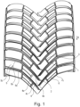
- Fig. 1 shows a plan view of a circumferential section of a tread belonging to a pneumatic vehicle tire with a directional profiling, wherein the pneumatic vehicle tire is to be mounted on the vehicle in such a way that it has the rolling direction indicated by the arrow R when driving forward.
- the tread has oblique grooves 1 which, when viewed from above, run parallel to one another and preferably slightly curved, which extend from the area of the tire's equatorial plane to the tread edges, run in a V shape across the width of the tread, are designed to the respective intended tread depth of in particular 6.0 mm to 9.5 mm at least over the majority of their extent and are thus the main (drainage) grooves of the tread, with the oblique grooves 1 running in different tread halves being offset from one another in the circumferential direction.
- the term "tread depth” refers to the depth of the deepest main (drainage) groove(s) in treads with main (drainage) grooves of different depths.
- each oblique groove 1 on the inside of the tread is adjoined by a notch-like groove 2 which opens into the respective oblique groove 1 running in the other tread half. Furthermore, in each tread half, two short grooves 3 run between circumferentially adjacent oblique grooves 1, which are inclined in the opposite direction to the oblique grooves 1 with respect to the circumferential direction.
- the oblique grooves 1 and the short grooves 3 divide the tread into central profile blocks 4 and shoulder-side profile blocks 5 belonging to shoulder-side profile block rows.
- the oblique grooves 1 extend in the area of the central profile blocks 4 in plan view to the axial direction at an angle of up to 50° and in the area of the shoulder-side profile blocks 5 to the axial direction at an angle of 0° to 20°.
- Each profile block 4, 5 has an outer block surface 4c (profile block 4), 5c (profile block 5) on the tread periphery, an incoming block edge 4a (profile block 4), 5a (profile block 5) formed on one adjacent oblique groove 1 and an outgoing block edge 4b (profile block 4), 5b (profile block 5) formed on the other adjacent oblique groove 1, whereby when the tire rolls while driving forward (arrow R), the incoming block edge 4a, 5a enters the ground before the outgoing block edge 4b, 5b.
- the middle profile blocks 4 located further outside the tread are each provided with an incision 6 extending from the block outer surface 4c.
- the other profile blocks 4, 5 are also each provided with an incision 6.
- Fig. 2 shows a top view of a middle profile block 4 with a cut 6 as well as partial areas of the oblique grooves 1 adjacent to the profile block 4 and partial areas of the short grooves 3 adjacent to the profile block 4.
- the cut 6 crosses the profile block 4 in its longitudinal extension, has a slightly curved cut center line m E which follows the cut in plan view, runs in plan view with respect to the axial direction in line with the block edges 4a, 4b and - with respect to the cut center line m E - preferably parallel or essentially parallel to the block edges 4a, 4b, has on the block outer surface 4c an incoming cut edge 6a which first enters the ground when the tire rolls when driving forwards (arrow R) and an outgoing cut edge 6b as well as an incoming cut end 7a on the inside of the tread which first enters the ground when the tire rolls when driving forwards and a When the tire rolls forward, the incoming incision edge 6a is covered by Points P 1 are inserted into the subsoil in front of the point
- the incision 6 is formed by an incision wall 8a extending from the incoming incision edge 6a, an incision wall 8b extending from the outgoing incision edge 6b ( Fig. 5, Fig. 6 ) and a cut bottom 8c and has a cut center surface M E ( Fig. 5, Fig. 6 : shown in dashed lines), a length l E determined on the block outer surface 4c along the already mentioned incision center line m E ( Fig. 2 ), a constant width b E ( Fig. 5, Fig.
- the incision base 8c runs at the maximum depth t E and thus extends at least over the majority of the length l E ( Fig. 2 ), in particular over at least 55%, preferably over at least 60%, of the length l E ( Fig. 2 ), and ends in the embodiment shown at shallow, edge-side incision areas in a manner known per se.
- the incision 6 continues in the area in which it reaches the maximum depth t E ( Fig. 4 ), in the radial direction, consists of a radially outer incision section 6 I , a middle incision section 6 II and a radially inner incision section 6 III extending to the incision base 8c.
- t E the maximum depth
- the radially outer incision section 6 I (in Fig. 5 and Fig. 6 barely recognizable), in plan view perpendicular to the incision center line m E ( Fig. 2 ) aligned cross-section (cf. position of section lines VV and VI-VI in Fig. 4 ), in the radial direction and has a length l I of preferably 0.5 mm to 1.5 mm, determined in the radial direction, based on the incision center area M E.
- the middle incision section 6 II runs, viewed in the cross section mentioned, straight and at an angle ⁇ to the radial direction of 15° to 35°, in particular of 20° to 30°. According to Fig. 3 and Fig.
- the radially inner incision section 6 III has two local wedging structures 9, the design of which will be discussed in more detail below.
- the radially inner incision section 6 III runs in the area outside the wedging structures 9, viewed in the mentioned cross section, in the radial direction, alternatively to this at an angle of up to 3°, wherein the radially inner incision section 6 III can be inclined in the same or opposite direction to the central incision section 6 II with respect to the radial direction.
- Fig. 10 which increases the Fig.
- connection area of the radially inner incision section 6 III to the middle incision section 6 II defines a depth level N related to the incision middle surface M E , which is located relative to the block outer surface 4c at a constant depth T N determined in the radial direction and from the level of the maximum depth t E of the incision 6 at a distance a N determined in the radial direction.
- the wedging structures 9 are therefore located radially within the depth level N, wherein the associated depth T N is at least 20%, in particular at least 25%, preferably at least 35%, of the maximum depth t E.
- the mentioned distance a N results from the difference between the maximum depth t E of the incision 6 and the depth T N of the depth level N.
- the wedging structures 9 are each formed or limited by two opposing, correspondingly designed, specially continuously curved wall sections 10 of the recess walls 8a, 8b.
- the recess walls 8a, 8b are unstructured surfaces 10 ⁇ ( Fig. 3 ), i.e. areas which are free of projections and/or depressions.
- Continuous curved means that the wall sections 10 are free of kinks (edges) and points in their interior, so that a tangential plane exists at every point on a wall section 10.
- “Corresponding” means that the width b E of the incision 6 in the area of the wall sections 10 is constant or varies by a maximum of 0.1 mm due to manufacturing.
- the wall sections 10 are also designed in such a way that they transition continuously ("kink-free", “edge-free") into the unstructured surfaces 10'. "Continuous transition” means that a tangential plane exists at every point at the transition of a wall section 10 to the corresponding unstructured surface 10 ⁇ .
- Fig. 4 and Fig. 5 an axis A 1 is drawn, which - as Fig. 4 shows - when viewed vertically on the unstructured surfaces 10 ⁇ perpendicular to the incision center line m E and through the middle of the incision center line m E (falls in Fig. 4 with the incision edges 6a, 6b) and which furthermore - like Fig. 5 shows - viewed in a cross-section oriented perpendicular to the incision center line m E in plan view, in the radially inner incision section 6 III runs centrally between the unstructured surfaces 10', ie in the radially inner incision section 6 III in the incision center surface M E .
- the wedging structures 9 are located on different sides of the axis A 1 , so that one wedging structure 9 is formed in one half of the incision and the other wedging structure 9 in the other half of the incision, wherein the wedging structures 9 are located at the same distance from the axis A 1.
- the wedging structures 9 are formed in such a way that, neglecting the curved course of the incision 4 in plan view (see Fig. 2 ), the wedging structures 9 can be transferred into each other by a 180° rotation about the axis A 1 (cf. Fig. 3 ).
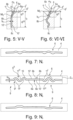
- wedging structures 9 The further design of the wedging structures 9 is described below in particular with reference to a single wedging structure 9 and with the aid of Fig. 7 to Fig. 9 , which show top views of the profile block 4 in the area of the notch 6 and in which the profile block 4 is Fig. 4 marked levels N 7 , N 8 , N 9 is rubbed off. The level Ns is also in Fig. 10 marked.
- the wedging structure 9 is circular segment-shaped, in particular semicircular, when viewed at the incision walls 8a, 8b, with the chord of the block outer surface 4c (cf. Fig. 2 ) and the incision edges 6a, 6b and is aligned parallel to the block outer surface 4c and the incision edges 6a, 6b and wherein the circular arc faces the incision base 8c.
- the wedging structure 9 is composed of a U-shaped, bulged, outer structural zone 9 I and an inner structural zone 9 II which runs around it, is opposite to the outer structural zone 9 I and bulges in a dome shape, wherein the free ends of the U-legs of the outer structural zone 9 I point towards the block outer surface 4c and the incision edges 6a, 6b.
- the outer structural zone 9 I and the inner structural zone 9 II begin together at a constant depth determined in the radial direction ( Fig. 4 ).
- the wedging structure 9 has a plane of symmetry E 1 running in the radial direction and in plan view (not shown) perpendicular to the incision center line m E.
- Fig. 10 The wedging structure 9, viewed in the cross-section lying in the plane of symmetry E 1 (cf. Fig. 6 and position of the section line VI-VI in Fig. 4 ), corresponding to the above-mentioned shape of the structural zones 9 I , 9 II , has an S-shaped curved course.
- the wedging structure 9 ends in the embodiment shown, in the cross-section lying in the plane of symmetry E 1 and in cross-sectional planes aligned parallel to the plane of symmetry E 1 and in relation to the incision center area M E , in front of the depth level N at a radially determined distance a 1 of at least 0.1 mm and points to the level of the incision base 8c in radial direction has a distance a 2 of at least 0.1 mm.
- the wedging structure 9 can extend to the level of the incision base 8c and/or to the depth level N.
- the wedging structure 9 has in the plane of symmetry E 1 in the radial direction a height hz related to the incision center area M E of 35% to 70%, in particular of 40% to 65%, preferably of 45% to 60%, particularly preferably of 50% to 60%, of the maximum depth t E , wherein the height hz in the embodiment is correspondingly matched to the distances a N , a 1 and a 2 .
- Each structural zone 9 I , 9 II is surrounded by a projection 11 I (outer structural zone 9 I , Fig. 8 ), 11 II (inner structural zone 9 II , Fig. 8 ) and a depression which is indented opposite the unstructured surface 10 ⁇ of the other, second incision wall 8a, 8b and corresponds to the projection 11 I , 11 II .
- the projection 11 I is U-shaped and the projection 11 II is dome-shaped.
- each wedging structure 9 the U-shaped projection 11 I is located on one incision wall 8a or 8b and the dome-shaped projection 11 II is located on the other incision wall 8a or 8b, with the dome-shaped projection 11 II protruding into the U-shape of the U-shaped projection 11 I.
- the U-shaped projection 11 I is thus formed together with the recess located on the same incision wall 8a, 8b, which corresponds to the dome-shaped projection 11 II located on the other incision wall 8a or 8b, by one of the already mentioned, continuously curved wall sections 10 ( Fig. 3 , Fig. 8 ) of the wedging structure 9.
- the dome-shaped projection 11 II together with the depression located on the same incision wall 8a, 8b, which corresponds to the U-shaped projection 11 I located on the other incision wall 8a or 8b, is delimited by the other continuously curved wall section 10 ( Fig. 3 , Fig. 8 ) of the wedging structure 9 is limited.
- Fig. 8 shows, is closer to the incoming incision end 7a (cf. Fig. 4 ) located wedging structure 9, the U-shaped projection 11 I is formed on the incision wall 8a extending from the incoming incision edge 6a and at the incision end 7b closer to the tread outer side (cf. Fig. 4 ) located wedging structure 9, the U-shaped projection 11 I is formed on the incision wall 8b extending from the tapering incision edge 6b.
- the inner structural zone 9 II - according to its dome-shaped bulging shape - viewed in the cross section lying in the plane of symmetry E 1 , runs in an arc shape, has a height h" of 55% to 65% of the height hz of the wedging structure 9 in relation to the incision center surface M E in the radial direction and defines a level Ns running through its maximum deflected point at a constant depth determined in the radial direction.
- the inner structural zone 9 II is thus, viewed in the cross section lying in the plane of symmetry E 1 , at the level N 8 - related to the incision center surface M E and determined perpendicular to the level of the unstructured surfaces 10 ⁇ adjacent to the inner structural zone 9 II ( Fig.
- the level Ns "divides" the inner structural zone 9 II into a radially outer zone part 9 II a and a radially inner zone part 9 II b.
- the radially inner zone part 9 II b is - compared to the radially outer zone part 9 II a in the cross-section lying in the symmetry plane E 1 and in relation to the incision center area M E - less curved and longer in the radial direction.
- the radially inner zone part 9 II b also has, viewed in the cross-section mentioned, a curvature that progressively increases starting from the level Ns in the direction of the incision base 8c, so that the curvature initially increases only slightly and then more strongly.
- the radially outer zone part 9 II a has, viewed in the cross-section mentioned, an essentially constant curvature.
- the "curvature” is understood to mean, as is known, the reciprocal of the radius of curvature, where the radius of curvature is the radius of the circle through which the Considering a cross-section lying on the plane of symmetry E 1 , the respective point on the plane of symmetry E 1 is best approximated.
- the outer structural zone 9 I is defined by the level Ns ( Fig. 10 ) is divided into a radially inner zone part 9'b which runs semi-circularly when viewed perpendicularly onto the incision walls 8a, 8b and two short radially outer zone parts 9 I a which run in the radial direction.
- the radially inner zone part 9 I b runs, viewed in cross-section perpendicular to its U-shape, i.e. viewed for example in the cross-section lying in the plane of symmetry E 1 , in a constant circular arc shape (see Fig. 3 in combination with Fig. 10 , radially inner zone part 9'b in Fig. 10 not quantified).
- the wedging structure 9 runs at level N 8 , viewed from above onto level Ns, in the form of a harmonic wave with a wavelength ⁇ and an amplitude A, which are each related to the incision center area M E and are constant according to the form of a harmonic wave at level Ns.
- the wedging structure 9 runs at level Ns according to the shape of its structural zones 9 I , 9 II ( Fig. 3, Fig. 4 ) over 1.5 wavelengths ⁇ .
- the amplitude A at level Ns is 90% to 200%, in particular 100% to 150%, preferably 115% to 135%, of the width b E of the notch 6 and the wavelength ⁇ at level N 8 is 500% to 1000%, in particular 600% to 800%, of the width b E of the notch 6.
- the incisions each have at least one wedging structure and can in particular have up to three wedging structures.
- the incisions with the wedging structures can also be formed in profile ribs running around the circumference, whereby the incisions can end on one or both sides within the profile ribs or within the profile blocks.
- the incisions can also be provided in shoulder-side profile blocks or in shoulder-side profile ribs, whereby it is preferred if the Wedging structure(s) are located within the ground contact area (corresponds to the statically determined footprint at a load of 70% of the maximum load-bearing capacity at an internal pressure of 85%, determined in accordance with ETRTO standards) of the tread.
- the raised, edge-side incision areas are optional, so that the incision can reach the maximum depth t E over its entire extent (length l E ).
- the wedging structure(s) are located in an incision area designed to the maximum depth, whereby the incision in this variant is made up of adjoining incision areas in plan view.
- the radially outer incision section 6 I and the middle incision section 6 II are also optional, so that in this design the incision 6, viewed in cross-section and in the radial direction, has no incision sections or is only formed from a single "incision section".
- the incisions run at an angle of 0° to 50° to the axial direction in plan view, whereby the angle in the case of non-straight incisions refers to a straight line connecting the ends of the incision center line in plan view.
- the incisions run straight or continuously curved, i.e. in a circular arc, in plan view at least over the majority of their length, whereby the wedging structure(s) are located in particular in the straight or curved section.
- the tread does not have to be designed in a direction-specific manner.
Landscapes
- Engineering & Computer Science (AREA)
- Mechanical Engineering (AREA)
- Tires In General (AREA)
Description
- Die Erfindung betrifft einen Fahrzeugluftreifen mit einem Laufstreifen mit Profilpositiven, welche mit in Draufsicht unter einem Winkel von 0° bis 50° zur axialen Richtung verlaufenden Einschnitten versehen sind, welche jeweils eine Breite von 0,4 mm bis 2,0 mm, eine maximale Tiefe von 70% bis 100% der Profiltiefe, einen Einschnittgrund und zwei Einschnittwände mit zumindest einer zur Laufstreifenperipherie beabstandeten, nicht bis zur Laufstreifenperipherie reichenden lokalen Verkeilungsstruktur aufweisen, wobei die Verkeilungsstruktur durch zwei einander gegenüberliegende, korrespondierende, durchgehend gekrümmte Wandabschnitte der Einschnittwände gebildet ist und wobei unstrukturierte Flächen der Einschnittwände an die durchgehend gekrümmten Wandabschnitte angrenzen.
- Ein derartiger Fahrzeugluftreifen ist beispielsweise aus der
DE 10 2020 201 635 A1 bekannt. Der Reifen weist einen Laufstreifen mit Profilpositiven auf, welche mit in Draufsicht unter einem Winkel von 0° bis 50° zur axialen Richtung verlaufenden Einschnitten versehen sind. Die Einschnittwände der Einschnitte sind jeweils mit einer Verkeilungsstruktur versehen, welche durch durchgehend gekrümmte Wandabschnitte der Einschnittwände gebildet ist. In der Tiefenposition der Verkeilungsstruktur ist ferner eine Einschnittverbreiterung aus zwei einander gegenüberliegenden Vertiefungen ausgebildet. Durch solche Einschnitte sollen unter anderem die Handlingeigenschaften und die Bremsperformance gleichermaßen vorteilhaft beeinflusst sein. - Die
WO 2022 002 425 A1 , welche einen Stand der Technik nach Art 54(3) EPÜ bildet, offenbart einen Fahrzeugluftreifen mit einem Laufstreifen mit Profilpositiven mit Einschnitten mit jeweils einem mittleren, in Draufsicht wellenförmig verlaufenden Einschnittabschnitt mit einer von der Laufstreifenperipherie ins Innere des Einschnittes hineinragenden, gewellten Verkeilungsstruktur. Die Verkeilungsstruktur schließt an drei aufeinanderfolgende jeweils über eine halbe Wellenlänge reichende Wellenabschnitte des mittleren Einschnittabschnittes an und setzt sich, betrachtet bei Sicht auf die Einschnittwände, aus einer zwischen den beiden äußeren Wellenabschnitten verlaufenden, U-förmigen äußeren Strukturzone und einer von dieser umlaufenen, an den mittleren Wellenabschnitt anschließenden, inneren Strukturzone zusammen. - Aus der
EP 2 560 830 B1 ist ein Fahrzeugluftreifen mit einem Laufstreifen mit Profilpositiven mit Einschnitten bekannt, welche sich, im Querschnitt betrachtet, jeweils aus einem radial äußeren Einschnittabschnitt, der in radialer Richtung eine Länge von 50% bis 90% der Tiefe des Einschnittes aufweist, und einem radial inneren Einschnittabschnitt zusammensetzen. Der radial äußere Einschnittabschnitt ist zur radialen Richtung unter einem Winkel von 0° bis 3° und der radial innere Einschnittabschnitt ist zur radialen Richtung unter einem Winkel von 15° bis 45° geneigt. Im Bereich des radial inneren Einschnittabschnittes weist zumindest die eine Einschnittwand, im Querschnitt betrachtet, einen kreisbogenförmig gekrümmt verlaufenden Wandabschnitt auf, wobei eine die Enden des Wandabschnittes verbindende gerade Linie zur radialen Richtung unter einem Winkel von 15° bis 45° verläuft. Der radial äußere Einschnittabschnitt verläuft, im Querschnitt betrachtet, beispielsweise gerade oder wellenförmig. Bei solchen Einschnitten ist die auftretende Kerbwirkung verringert, wodurch die materialermüdende Belastung am Einschnittgrund reduziert und die Haltbarkeit des Einschnittes erhöht ist. - Die
EP 0 958 945 B1 offenbart einen Fahrzeugluftreifen mit einem laufrichtungsgebunden ausgeführten Laufstreifen mit Profilpositiven mit jeweils zumindest paarweise angeordneten, in Draufsicht U-förmig verlaufenden Einschnitten, wobei der eine Einschnitt den anderen Einschnitt umläuft. Die freien Enden der U-förmig verlaufenden Einschnitte münden über die auslaufende Kante des zugehörigen Profilpositivs in die jeweils angrenzende Rille. Solche Einschnitte sollen im Hinblick auf die Traktions- und Bremseigenschaften vorteilhaft sein. - Der Erfindung liegt die Aufgabe zugrunde, bei einem Fahrzeugluftreifen der eingangs genannten Art eine Verkeilungsstruktur zur Verfügung zu stellen, mittels welcher die Schnee- und Nässeperformance über den Laufstreifenabrieb optimiert wird, wobei die für die Kraftübertagung auf den Untergrund vorteilhafte Verkeilungswirkung erhalten bleiben soll.
- Gelöst wird die gestellte Aufgabe erfindungsgemäß dadurch, dass die Verkeilungsstruktur, bei Sicht auf die Einschnittwände betrachtet, kreissegmentförmig, insbesondere halbkreisförmig, ausgeführt ist und sich aus einer kuppelförmig ausgebauchten, inneren Strukturzone und einer diese U-förmig umlaufenden, entgegengesetzt zur inneren Strukturzone ausgebauchten, äußeren Strukturzone mit zur Laufstreifenperipherie weisenden U-Schenkel zusammensetzt, sodass der durchgehend gekrümmte Wandabschnitt der einen Einschnittwand einen U-förmigen Vorsprung und der durchgehend gekrümmte Wandabschnitt der anderen Einschnittwand einen in den U-förmigen Vorsprung hineinragenden kuppelförmigen Vorsprung mitbegrenzt.
- Die erfindungsgemäße Verkeilungsstruktur weist durch ihre speziell ausgeführten Strukturzonen gegenüber bisher bekannten Verkeilungsstrukturen in der Längserstreckung des Einschnittes eine bessere Verkeilungswirkung auf, wodurch die Profilpositive besonders wirkungsvoll gegeneinander stabilisiert und in der Folge die Kraftübertragung bei Lenk-, Brems- und Traktionsvorgängen weiter verbessert ist. Mit fortschreitendem Laufstreifenabrieb tritt die Verkeilungsstruktur mehr in Richtung zur Peripherie des Laufstreifens. Dabei werden einerseits an der Verkeilungsstruktur ausgebildete, ausgeprägt gewellt verlaufende Griffkanten nahe bei oder an der Laufstreifenperipherie zur Verfügung gestellt, welche eine hohe abgewickelte Kantenlänge aufweisen und den mit zunehmendem Laufstreifenabrieb abnehmenden Traktionseigenschaften auf Schnee wirkungsvoll entgegenwirken, wodurch die Traktionseigenschaften auf hohem Niveau gehalten werden. Anderseits verbessert die nun bis zu Laufstreifenperipherie reichende U-förmig umlaufende äußere Strukturzone - bedingt durch ihre U-Form - beim Fahren auf nasser Fahrbahn die Entwässrung der Außenfläche der Profilpositive, was für die Nassgriffeigenschaften von Vorteil ist. Die Verkeilungsstruktur zeigt daher einen doppelten Effekt, verbessert zum einen bei neuem bzw. wenig abgeriebenen Laufstreifen die Kraftübertragung auf den Untergrund und trägt zum anderen bei entsprechend abgeriebenem Laufstreifen zur Aufrechterhaltung einer guten Schnee- und Nässeperformance bei.
- Gemäß einer bevorzugten Ausführung ist die komplette Verkeilungsstruktur radial innerhalb eines Tiefenniveaus ausgebildet, welches gegenüber der Laufstreifenperipherie in einer in radialer Richtung ermittelten konstanten Tiefe von zumindest 20%, insbesondere von zumindest 25%, bevorzugt von zumindest 35%, der maximalen Tiefe des Einschnittes verläuft. Die Verkeilungsstruktur kann daher in einem Abstand zu diesem Tiefenniveau oder komplett radial innerhalb dieses Tiefenniveaus ausgebildet sein. Sie reicht in Richtung Laufstreifenperipherie jedoch nicht über dieses Niveau hinaus. Eine in einer solchen "Tiefenposition" ausgebildete Verkeilungsstruktur ist für die Aufrechterhaltung der Traktionseigenschaften auf Schnee mit zunehmenden Laufstreifenabrieb besonders günstig.
- Gemäß einer weiteren bevorzugten Ausführung weist die Verkeilungsstruktur eine in radialer Richtung und in Draufsicht senkrecht zur Einschnittmittellinie des Einschnittes verlaufende Symmetrieebene auf. Diese Maßnahme ist im Hinblick auf eine gleichmäßige Wirkungsweise der Verkeilungsstruktur von Vorteil.
- Nachfolgend wird auf eine Vielzahl von bevorzugten Ausgestaltungen der letztgenannten bevorzugten Ausführung sowie auf besonders bevorzugte Varianten dieser Ausgestaltungen eingegangen.
- Bei einer ersten bevorzugten Ausgestaltung weist die Verkeilungsstruktur, im in der Symmetrieebene liegenden Querschnitt betrachtet, bezogen auf die Einschnittmittelfläche in radialer Richtung eine Höhe von 35% bis 70%, insbesondere von 40% bis 65%, bevorzugt von 45% bis 60%, besonders bevorzugt von 50% bis 60%, der maximalen Tiefe des Einschnittes auf. Dadurch ist die Schnee- und Nässeperformance über den Laufstreifenabrieb weiter optimiert.
- Gemäß einer bevorzugten Variante der ersten bevorzugten Ausgestaltung weist die innere Strukturzone, im in der Symmetrieebene liegenden Querschnitt betrachtet, bezogen auf die Einschnittmittelfläche in radialer Richtung eine Höhe von 55% bis 65% der Höhe der Verkeilungsstruktur auf. Die bereits erwähnten, mit zunehmendem Laufstreifenabrieb an die Laufstreifenperipherie tretenden, ausgeprägt gewellt verlaufen Griffkanten bleiben daher vorteilhafterweise entsprechend lange erhalten.
- Eine zweite bevorzugte Ausgestaltung ist dadurch gekennzeichnet, dass die innere Strukturzone, im in der Symmetrieebene liegenden Querschnitt betrachtet, ein in einer in radialer Richtung ermittelten konstanten Tiefe durch ihre maximal ausgelenkte Stelle verlaufendes Niveau aufweist, welches die innere Strukturzone in einen radial äußeren Zonenteil und einen radial inneren Zonenteil teilt, wobei, im erwähnten Querschnitt betrachtet, der radial innere Zonenteil - gegenüber dem radial äußeren Zonenteil - bezogen auf die Einschnittmittelfläche schwächer gekrümmt ausgeführt ist.
- Gemäß einer ersten bevorzugten Variante der zweiten bevorzugten Ausgestaltung ist der radial innere Zonenteil, im in der Symmetrieebene liegenden Querschnitt betrachtet, gegenüber dem radial äußeren Zonenteil in radialer Richtung länger ausgeführt.
- Die bei der zweiten bevorzugten Ausgestaltung und der zugehörigen ersten bevorzugten Variante vorliegende asymmetrische Krümmung des inneren Zonenteils ermöglicht bereits nach geringem Laufstreifenabrieb, nämlich nach Abrieb des kurzen radial äußeren Zonenteiles, eine entsprechend große Amplitude der an Laufstreifenperipherie auftretenden, wellenförmig verlaufenden Kanten. Da die Amplitude unmittelbar mit der Länge der Kante korreliert, ist diese Ausgestaltung für die Schneeperformance von weiterem Vorteil.
- Eine zweite bevorzugten Variante der zweiten bevorzugten Ausgestaltung ist dadurch gekennzeichnet, dass der radial innere Zonenteil, im in der Symmetrieebene liegenden Querschnitt betrachtet, eine Krümmung aufweist, welche vom durch die maximal ausgelenkte Stelle verlaufendem Niveau in Richtung zum Einschnittgrund auf progressive Weise zunimmt. Dadurch bleibt eine möglichst lange Kante an der Laufstreifenperipherie über den Laufstreifenabrieb erhalten, was ebenfalls für die Schneeperformance von Vorteil ist.
- Gemäß einer dritten bevorzugten Ausgestaltung verläuft die Verkeilungsstruktur am Niveau, welches durch die maximal ausgelenkte Stelle der inneren Strukturzone verläuft, in Form einer harmonischen Welle sowie über 1,5 Wellenlängen.
- Gemäß einer bevorzugten Variante der dritten bevorzugten Ausgestaltung beträgt die Wellenlänge der harmonischen Welle 500% bis 1000%, insbesondere 600% bis 800%, der Breite des Einschnittes. Dies ist für die Verkeilungswirkung von weiterem Vorteil.
- Gemäß einer weiteren bevorzugten Variante der dritten bevorzugten Ausgestaltung weist die harmonische Welle eine Amplitude von 90% bis 200%, insbesondere von 100% bis 150%, bevorzugt von 115% bis 135%, der Breite des Einschnittes auf. Dies ist ebenfalls für die Verkeilungswirkung von zusätzlichem Vorteil.
- Eine weitere bevorzugte Ausführung ist dadurch gekennzeichnet, gekennzeichnet, dass zu den Einschnitten Einschnitte gehören, welche jeweils zwei der Verkeilungsstrukturen aufweisen, wobei sich die eine Verkeilungsstruktur in der einen Einschnitthälfte und die andere Verkeilungsstruktur in der anderen Einschnitthälfte befindet, wobei sich die Eischnitthälften durch Teilung des Einschnittes in Draufsicht ergeben. Dies ermöglicht ein besonders gleichmäßige Verkeilungswirkung über die Einschittlängserstreckung.
- Gemäß einer bevorzugten Variante der letztgenannten bevorzugte Ausführung sind die Verkeilungsstrukturen derart ausgebildet, dass diese durch eine Drehung um 180° um eine in radialer Richtung sowie im Bereich zwischen den Verkeilungsstrukturen verlaufende Achse ineinander überführbar sind. Diese Maßnahme verbessert in besonders gleichmäßiger Weise sowohl die Traktion als auch das Bremsverhalten auf Schnee.
- Eine weitere bevorzugte Ausführung ist dadurch gekennzeichnet, dass zu den Einschnitten Einschnitte gehören, welche die zugehörigen Profilpositive durchqueren. Durchquerende Einschnitte sind einerseits für die Nässeperformance von Vorteil, da sie die Wasserableitung in die Rillen begünstigen. Anderseits weisen die Profilpositive durch die durchquerenden Einschnitte eine ausgeprägte Biegefähigkeit auf, sodass die Einschnittkanten besser in Schnee eingreifen.
- Eine weitere bevorzugte Ausführung ist dadurch gekennzeichnet, dass zu den Einschnitten Einschnitte gehören, welche jeweils einen den Einschnittgrund mitumfassenden, zur radialen Richtung unter einem Winkel von 0° bis 3° verlaufenden, radial inneren Einschnittabschnitt und einen an diesen anschließenden zur radialen Richtung unter einem Winkel von 15° bis 35°, insbesondere von 20° bis 30°, verlaufenden weiteren Einschnittabschnitt aufweisen, wobei sich die Verkeilungsstruktur(en) im radial inneren Einschnittabschnitt befindet bzw. befinden. Ein solcher weiterer Einschnittabschnitt ermöglicht einen für die Schneetraktion besonders vorteilhaften Eingriffswinkel der Einschnittkanten.
- Weitere Merkmale, Vorteile und Einzelheiten der Erfindung werden nun anhand der Zeichnung, die schematisch ein Ausführungsbeispiel der Erfindung zeigt, näher erläutert. Dabei zeigen
-
Fig. 1 eine vereinfachte Draufsicht auf eine Umfangsabschnitt eines Laufstreifens eines Fahrzeugluftreifens mit einer Ausführungsvariante der Erfindung, -
Fig. 2 eine vergrößerte Draufsicht auf den im Detail Z2 derFig. 1 befindlichen Profilblock des Laufstreifens, -
Fig. 3 eine Visualisierung eines im Profilblock ausFig. 2 ausgebildeten Einschnittes (Abzugskörper des Einschnittes), -
Fig. 4 eine Frontansicht auf die Visualisierung des Einschnittes gemäß der inFig. 3 durch den Pfeil S4 angedeuteten Sichtrichtung, -
Fig. 5 einen Schnitt durch den Einschnitt gemäß der Linie V-V inFig. 4 mit an den Einschnitt angrenzendem Gummimaterial des Profilblockes, -
Fig. 6 einen Schnitt durch den Einschnitt gemäß der Linie VI-VI derFig. 4 mit an den Einschnitt angrenzendem Gummimaterial des Profilblockes, -
Fig. 7 eine Draufsicht auf einen Ausschnitt des Profilblockes ausFig. 2 im Bereich des Einschnittes, wobei der Profilblock auf das inFig. 4 gekennzeichnete Niveau N7 abgerieben ist, -
Fig. 8 eine Draufsicht analog zuFig. 7 , wobei der Profilblock auf das inFig. 4 gekennzeichnete Niveau Ns abgerieben ist, -
Fig. 9 eine Draufsicht analog zuFig. 7 , wobei der Profilblock auf das inFig. 4 gekennzeichnete Niveau N9 abgerieben ist, -
Fig. 10 den Querschnitt ausFig. 6 in vergrößerter Darstellung und -
Fig. 11 eine in ihrer Größe zuFig. 10 passende Ansicht des Details Z11 ausFig. 8 . - Gemäß der Erfindung ausgeführte Fahrzeugluftreifen sind Reifen für Kraftfahrzeuge, insbesondere für mehrspurige Kraftfahrzeuge, sowie vorzugsweise Reifen in Radialbauart für Personenkraftwagen, Vans oder Light-Trucks (Leichte LKWs mit zGM ≤ 7,5 t), wobei die Reifen insbesondere für den Ganzjahreseinsatz vorgesehen sind.
-
Fig. 1 zeigt eine Draufsicht auf einen Umfangsabschnitt eines zu einem Fahrzeugluftreifen gehörenden Laufstreifens mit einer laufrichtungsgebunden ausgeführten Profilierung, wobei der Fahrzeugluftreifen derart am Fahrzeug zu montieren ist, dass er die durch den Pfeil R angedeutete Abrollrichtung bei Vorwärtsfahrt aufweist. - Der Laufstreifen weist in jeder Laufstreifenhälfte in Draufsicht parallel zueinander und vorzugsweise leicht gebogen verlaufende Schrägrillen 1 auf, welche sich vom Bereich der Reifenäquatorialebene bis zu den Laufstreifenrändern erstrecken, insgesamt V-förmig über die Laufstreifenbreite verlaufen, zumindest über den Großteil ihrer Erstreckung auf die jeweils vorgesehene Profiltiefe von insbesondere 6,0 mm bis 9,5 mm ausgeführt und somit die Haupt(entwässerungs)rillen des Laufstreifens sind, wobei die in unterschiedlichen Laufstreifenhälften verlaufenden Schrägrillen 1 in Umfangsrichtung zueinander versetzt sind. Der Ausdruck "Profiltiefe" bezeichnet bei Laufstreifen mit verschieden tief ausgeführten Haupt(entwässerungs)rillen die Tiefe der am tiefsten ausgeführten Haupt(entwässerungs)rille(n). An das laufstreifeninnenseitige Ende jeder Schrägrille 1 schließt eine einschnittartige Rille 2 an, welche in die jeweilige in der anderen Laufstreifenhälfte verlaufende Schrägrille 1 einmündet. Ferner verlaufen in jeder Laufstreifenhälfte zwischen in Umfangsrichtung benachbarten Schrägrillen 1 jeweils zwei Kurzrillen 3, welche bezüglich der Umfangsrichtung gegensinnig zu den Schrägrillen 1 geneigt sind.
- Die Schrägrillen 1 und die Kurzrillen 3 gliedern den Laufstreifen in mittlere Profilblöcke 4 und in zu schulterseitigen Profilblockreihen gehörende schulterseitige Profilblöcke 5. Die Schrägrillen 1 erstrecken sich im Bereich der mittleren Profilblöcke 4 in Draufsicht zur axialen Richtung unter einem Winkel von bis zu 50° und im Bereich der schulterseitigen Profilblöcke 5 zur axialen Richtung unter einem Winkel von 0° bis 20°.
- Jeder Profilblock 4, 5 weist an der Laufstreifenperipherie eine Blockaußenfläche 4c (Profilblock 4), 5c (Profilblock 5), eine an der einen angrenzenden Schrägrille 1 ausgebildete, einlaufende Blockkante 4a (Profilblock 4), 5a (Profilblock 5) und eine an der anderen angrenzenden Schrägrille 1 ausgebildete, auslaufende Blockkante 4b (Profilblock 4), 5b (Profilblock 5) auf, wobei beim Abrollen des Reifens bei Vorwärtsfahrt (Pfeil R) die einlaufende Blockkante 4a, 5a vor der auslaufenden Blockkante 4b, 5b in den Untergrund eintritt. Die weiter laufstreifenaußenseitig befindlichen, mittleren Profilblöcke 4 sind jeweils mit einem von der Blockaußenfläche 4c ausgehenden Einschnitt 6 versehen. Bevorzugter Weise sind auch die weiteren Profilblöcke 4, 5 jeweils mit einem Einschnitt 6 versehen.
- Die weitere Ausgestaltung der Einschnitte 6 wird nachfolgend anhand eines einzelnen Einschnittes 6 erläutert.
-
Fig. 2 zeigt eine Draufsicht auf einen mittleren Profilblock 4 mit einem Einschnitt 6 sowie Teilbereiche der an den Profilblock 4 angrenzenden Schrägrillen 1 und Teilbereich der an den Profilblock 4 angrenzenden Kurzrillen 3. Der Einschnitt 6 durchquert den Profilblock 4 in Längserstreckung, weist eine in Draufsicht dem Einschnittverlauf folgende, leicht gebogen verlaufende Einschnittmittellinie mE auf, verläuft in Draufsicht bezüglich der axialen Richtung übereinstimmend zu den Blockkanten 4a, 4b geneigt sowie - bezogen auf die Einschnittmittellinie mE - vorzugsweise parallel bzw. im Wesentlichen parallel zu den Blockkanten 4a, 4b, weist an der Blockaußenfläche 4c eine beim Abrollen des Reifens bei Vorwärtsfahrt (Pfeil R) zuerst in den Untergrund eintretende, einlaufende Einschnittkante 6a und eine auslaufende Einschnittkante 6b sowie ein beim Abrollen des Reifens bei Vorwärtsfahrt zuerst in den Untergrund eintretendes, laufstreifeninnenseitiges, einlaufendes Einschnittende 7a und ein laufstreifenaußenseitiges, auslaufendes Einschnittende 7b auf. Beim Abrollen des Reifens bei Vorwärtsfahrt treten auf der einlaufenden Einschnittkante 6a liegende Punkte P1 jeweils vor dem exakt in Umfangsrichtung gegenüberliegenden, auf der auslaufenden Einschnittkante 6b liegenden Punkt P2 in den Untergrund ein. InFig. 2 sind zwei solcher Punkte P1, P2 exemplarisch eingezeichnet. - Wie insbesondere
Fig. 3 ,Fig. 5 und Fig. 6 in Kombination zeigen, ist der Einschnitt 6 durch eine von der einlaufenden Einschnittkante 6a ausgehende Einschnittwand 8a, eine von der auslaufenden Einschnittkante 6b ausgehende Einschnittwand 8b (Fig. 5, Fig. 6 ) sowie einen Einschnittgrund 8c begrenzt und weist eine von der Einschnittmittellinie mE ausgehende, übereinstimmend zu den Einschnittwänden 8a, 8b beabstandete Einschnittmittelfläche ME (Fig. 5, Fig. 6 : gestrichelt eingezeichnet), eine an der Blockaußenfläche 4c entlang der bereits erwähnten Einschnittmittellinie mE ermittelte Länge lE (Fig. 2 ), eine zwischen sowie senkrecht zu den Einschnittwänden 8a, 8b ermittelte, konstante Breite bE (Fig. 5, Fig. 6 ) von 0,4 mm bis 2,0 mm, insbesondere von bis zu 1,2 mm, besonders bevorzugt von bis zu 0,8 mm, und zumindest über den Großteil seiner Länge lE eine in radialer Richtung ermittelte konstante maximale Tiefe tE (Tiefe an der jeweils tiefsten Stelle,Fig. 4 bis Fig. 6 ) von 70% bis 100%, insbesondere von höchstens 95%, der Profiltiefe auf. GemäßFig. 4 verläuft der Einschnittgrund 8c auf der maximalen Tiefe tE und erstreckt sich somit zumindest über den Großteil der Länge lE (Fig. 2 ), insbesondere über zumindest 55%, bevorzugt über zumindest 60%, der Länge lE (Fig. 2 ), und endet beim gezeigten Ausführungsbeispiel an in an sich bekannter Weise seichter ausgeführten, randseitigen Einschnittbereichen. - Gemäß
Fig. 3 und Fig. 4 setzt sich der Einschnitt 6 in jenem Bereich, in welchem er auf die maximale Tiefe tE (Fig. 4 ) reicht, in radialer Richtung aus einem radial äußeren Einschnittabschnitt 6I, einem mittleren Einschnittabschnitt 6II und einem bis zum Einschnittgrund 8c reichenden, radial inneren Einschnittabschnitt 6III zusammen. In den erwähnten, seichter ausgeführten, randseitigen Einschnittbereichen sind insbesondere ausschließlich der radial äußere Einschnittabschnitt 6I und der mittlere Einschnittabschnitt 6II vorhanden. - Wie
Fig. 5 und Fig. 6 zeigen, verläuft der radial äußere Einschnittabschnitt 6I (inFig. 5 und Fig. 6 kaum erkennbar), im in Draufsicht senkrecht zur Einschnittmittellinie mE (Fig. 2 ) ausgerichteten Querschnitt betrachtet (vergl. Lage der Schnittlinien V-V und VI-VI inFig. 4 ), in radialer Richtung und weist eine auf die Einschnittmittelfläche ME bezogene, in radialer Richtung ermittelte Länge lI von vorzugsweise 0,5 mm bis 1,5 mm auf. Der mittlere Einschnittabschnitt 6II verläuft, im erwähnten Querschnitt betrachtet, gerade sowie zur radialen Richtung unter einem Winkel α von 15° bis 35°, insbesondere von 20° bis 30°. GemäßFig. 3 und Fig. 4 weist der radial innere Einschnittabschnitt 6III zwei lokale Verkeilungsstrukturen 9 auf, auf deren Ausgestaltung noch genauer eingegangen wird. WieFig. 5 zeigt, verläuft der radial innere Einschnittabschnitt 6III im Bereich außerhalb der Verkeilungsstrukturen 9, im erwähnten Querschnitt betrachtet, in radialer Richtung, alternativ zu dieser unter einem Winkel von bis zu 3°, wobei der radial innere Einschnittabschnitt 6III bezüglich der radialen Richtung gleich- oder gegensinnig zum mittleren Einschnittabschnitt 6II geneigt sind kann. GemäßFig. 10 , welche eine Vergrößerung derFig. 6 ist, definiert der Anschlussbereich des radial inneren Einschnittabschnittes 6III an den mittlere Einschnittabschnitt 6II ein auf die Einschnittmittelfläche ME bezogenes Tiefenniveau N, welches sich gegenüber der Blockaußenfläche 4c in einer in radialer Richtung ermittelten konstanten Tiefe TN und vom Niveau der maximalen Tiefe tE des Einschnittes 6 in einem in radialer Richtung ermittelten Abstand aN befindet. Die Verkeilungsstrukturen 9 befinden sich daher radial innerhalb des Tiefenniveaus N, wobei die zugehörige Tiefe TN zumindest 20%, insbesondere zumindest 25%, bevorzugt zumindest 35%, der maximalen Tiefe tE beträgt. Der erwähnte Abstand aN resultiert aus der Differenz der maximalen Tiefe tE des Einschnittes 6 und der Tiefe TN des Tiefenniveaus N. - Gemäß
Fig. 3 undFig. 10 sind die Verkeilungsstrukturen 9 jeweils von zwei einander gegenüberliegenden, korrespondierend ausgebildeten, speziell durchgehend gekrümmten Wandabschnitten 10 der Einschnittwände 8a, 8b gebildet bzw. begrenzt. Im Bereich außerhalb der Wandabschnitte 10 sind die Einschnittwände 8a, 8b unstrukturierte Flächen 10` (Fig. 3 ), also Flächen, welche frei von Vorsprüngen und/oder Vertiefungen sind. "Durchgehend gekrümmt" bedeutet, dass die Wandabschnitte 10 in ihrem Inneren frei von Knickstellen (Kanten) und Spitzen sind, sodass in jedem Punkt auf einem Wandabschnitt 10 eine Tangentialebene existiert. "Korrespondierend" bedeutet, dass die Breite bE des Einschnittes 6 im Bereich der Wandabschnitte 10 konstant ist oder fertigungsbedingt um höchstens 0,1 mm variiert. Beim gezeigten Ausführungsbeispiel sind die Wandabschnitte 10 ferner derart gestaltet, dass diese stetig ("knickfrei", "kantenfrei") in die unstrukturierten Flächen 10' übergehen. "Stetig übergehen" bedeute, dass in jedem Punkt am Übergang eines Wandabschnittes 10 zur entsprechenden unstrukturierten Fläche 10` eine Tangentialebene existiert. - In
Fig. 4 undFig. 5 ist eine Achse A1 eingezeichnet, welche - wieFig. 4 zeigt - bei senkrechter Sicht auf die unstrukturierten Flächen 10` senkrecht zur Einschnittmittellinie mE sowie durch die Mitte der Einschnittmittellinie mE (fällt inFig. 4 mit den Einschnittkanten 6a, 6b zusammen) verläuft und welche ferner- wieFig. 5 zeigt - im in Draufsicht senkrecht zur Einschnittmittellinie mE ausgerichteten Querschnitt betrachtet, im radial inneren Einschnittabschnitt 6III mittig zwischen den unstrukturierten Flächen 10', d.h. im radial inneren Einschnittabschnittes 6III in der Einschnittmittelfläche ME, verläuft. - Gemäß
Fig. 4 befinden sich die Verkeilungsstrukturen 9 an unterschiedlichen Seiten der Achse A1, sodass die eine Verkeilungsstruktur 9 in der einen Einschnitthälfte und die andere Verkeilungsstruktur 9 in der anderen Einschnitthälfte ausgebildet ist, wobei sich die Verkeilungsstrukturen 9 in übereinstimmenden Abständen zur Achse A1 befinden. Die Verkeilungsstrukturen 9 sind derart ausgebildet, dass, unter Vernachlässigung des in Draufsicht gebogenen Verlaufes des Einschnittes 4 (sieheFig. 2 ), die Verkeilungsstrukturen 9 durch eine 180°-Drehung um die Achse A1 ineinander überführbar sind (vergl.Fig. 3 ). - Die weitere Ausgestaltung der Verkeilungsstrukturen 9 wird nachfolgend insbesondere unter Bezugnahme auf eine einzelne Verkeilungsstruktur 9 sowie unter Zuhilfenahme von
Fig. 7 bis Fig. 9 , welche Draufsichten auf den Profilblock 4 im Bereich des Einschnittes 6 zeigen und in welchen der Profilblock 4 auf die inFig. 4 gekennzeichneten Niveaus N7, N8, N9 abgerieben ist. Das Niveau Ns ist ferner inFig. 10 eingezeichnet. - Wie
Fig. 3 und Fig. 4 in Kombination zeigen, ist die Verkeilungsstruktur 9 bei Sicht auf die Einschnittwände 8a, 8b kreissegmentförmig, insbesondere halbkreisförmig, wobei die Kreissehne der Blockaußenfläche 4c (vergl.Fig. 2 ) und den Einschnittkanten 6a, 6b zugewandt ist sowie parallel zur Blockaußenfläche 4c und den Einschnittkanten 6a, 6b ausgerichtet ist und wobei der Kreisbogen dem Einschnittgrund 8c zugewandt ist. Die Verkeilungsstruktur 9 setzt sich aus einer U-förmig verlaufenden, ausgebauchten, äußeren Strukturzone 9I und einer von dieser umlaufenen, zur äußeren Strukturzone 9I entgegengesetzt und kuppelförmig ausgebauchten, inneren Strukturzone 9II zusammen, wobei die freien Enden der U-Schenkel der äußeren Strukturzone 9I zur Blockaußenfläche 4c und den Einschnittkanten 6a, 6b weisen. Bevorzugter Weise beginnen die äußere Strukturzone 9I und die innere Strukturzone 9II gemeinsam in einer in radialer Richtung ermittelten konstanten Tiefe (Fig. 4 ). - Gemäß
Fig. 4 weist die Verkeilungsstruktur 9 eine in radialer Richtung und in Draufsicht (nicht gezeigt) senkrecht zur Einschnittmittellinie mE verlaufende Symmetrieebene E1 auf. GemäßFig. 10 weist die Verkeilungsstruktur 9, im in der Symmetrieebene E1 liegenden Querschnitt betrachtet (vergl.Fig. 6 und Lage der Schnittlinie VI-VI inFig. 4 ), entsprechend der erwähnten Gestalt der Strukturzonen 9I, 9II, einen S-förmig geschwungen Verlauf auf. Die Verkeilungsstruktur 9 endet beim gezeigten Ausführungsbeispiel, im in der Symmetrieebene E1 liegenden Querschnitt sowie in parallel zur Symmetrieebene E1 ausgerichteten Querschnittebenen betrachtet und bezogen auf die Einschnittmittelfläche ME, vor dem Tiefenniveau N in einem radialer Richtung ermittelten Abstand a1 von zumindest 0,1 mm und weist zum Niveau des Einschnittgrundes 8c in radialer Richtung einen Abstand a2 von zumindest 0,1 mm auf. Alternativ kann die Verkeilungsstruktur 9 bis zum Niveau des Einschnittgrundes 8c und/oder bis zum Tiefenniveau N reichen. - Die Verkeilungsstruktur 9 weist in der Symmetrieebene E1 in radialer Richtung eine auf die Einschnittmittelfläche ME bezogene Höhe hz von 35% bis 70%, insbesondere von 40% bis 65%, bevorzugt von 45% bis 60%, besonders bevorzugt von 50% bis 60%, der maximalen Tiefe tE auf, wobei die Höhe hz beim Ausführungsbeispiel auf die Abstände aN, a1 und a2 entsprechend abgestimmt ist.
- Jede Strukturzone 9I, 9II ist von einem gegenüber der jeweiligen unstrukturierten Fläche 10` der einen Einschnittwand 8a, 8b abragenden Vorsprung 11I (äußere Strukturzone 9I,
Fig. 8 ), 11II (innere Strukturzone 9II,Fig. 8 ) und einer gegenüber der unstrukturierten Fläche 10` der jeweils anderen, zweiten Einschnittwand 8a, 8b eingebuchteten, mit dem Vorsprung 11I, 11II korrespondierenden Vertiefung gebildet. Entsprechend der erwähnten Form der Strukturzonen 9I, 9II ist der Vorsprung 11I U-förmig und der Vorsprung 11II kuppelförmig. Da die innere Strukturzone 9II zur äußeren Strukturzone 9I, wie ebenfalls bereits erwähnt, entgegengesetzt ausgebaucht ist, befindet sich bei jeder Verkeilungsstruktur 9 der U-förmige Vorsprung 11I an der einen Einschnittwand 8a bzw. 8b und der kuppelförmige Vorsprung 11II an der jeweils anderen Einschnittwand 8a bzw. 8b, wobei der kuppelförmige Vorsprung 11II in die U-Form des U-förmigen Vorsprung 11I hineinragt. Der U-förmige Vorsprung 11I ist somit gemeinsam mit der an derselben Einschnittwand 8a, 8b befindlichen Vertiefung, welche mit dem an der jeweils anderen Einschnittwand 8a bzw. 8b befindlichen kuppelförmigen Vorsprung 11II korrespondiert, von einem der bereits erwähnten, durchgehend gekrümmten Wandabschnitte 10 (Fig. 3 ,Fig. 8 ) der Verkeilungsstruktur 9 begrenzt. In analoger Weise ist der kuppelförmige Vorsprung 11II gemeinsam mit der an derselben Einschnittwand 8a, 8b befindlichen Vertiefung, welche mit dem an der jeweils anderen Einschnittwand 8a bzw. 8b befindlichen U-förmigen Vorsprung 11I korrespondiert, von dem anderen durchgehend gekrümmten Wandabschnitt 10 (Fig. 3 ,Fig. 8 ) der Verkeilungsstruktur 9 begrenzt. - Wie
Fig. 8 zeigt, ist bei der näher zum einlaufenden Einschnittende 7a (vergl.Fig. 4 ) befindlichen Verkeilungsstruktur 9 der U-förmige Vorsprung 11I an der von der einlaufenden Einschnittkante 6a ausgehenden Einschnittwand 8a ausgebildet und bei der näher zum laufstreifenaußenseitigen Einschnittende 7b (vergl.Fig. 4 ) befindlichen Verkeilungsstruktur 9 ist der U-förmige Vorsprung 11I an der von der auslaufenden Einschnittkante 6b ausgehenden Einschnittwand 8b ausgebildet. - Wie
Fig. 10 zeigt, verläuft die innere Strukturzone 9II - entsprechend ihrer kuppelförmig ausgebauchten Form - im in der Symmetrieebene E1 liegenden Querschnitt betrachtet, bogenförmig, weist bezogen auf die Einschnittmittelfläche ME in radialer Richtung eine Höhe h" von 55% bis 65% der Höhe hz der Verkeilungsstruktur 9 auf und definiert ein in einer in radialer Richtung ermittelten konstanten Tiefe durch ihre maximal ausgelenkte Stelle verlaufendes Niveau Ns. Die innere Strukturzone 9II ist somit, im in der Symmetrieebene E1 liegenden Querschnitt betrachtet, am Niveau N8 - bezogen auf die Einschnittmittelfläche ME und ermittelt senkrecht zum Niveau der an die innere Strukturzone 9II angrenzenden unstrukturierten Flächen 10` (Fig. 3 ) der Einschnittwände 8a, 8b - am stärksten ausgelenkt (vergl.Fig. 3 ). Das Niveau Ns "teilt" die innere Strukturzone 9II in einen radial äußeren Zonenteil 9IIa und einen radial inneren Zonenteil 9IIb. Der radial innere Zonenteil 9IIb ist - jeweils gegenüber dem radial äußeren Zonenteil 9IIa im in der Symmetrieebne E1 liegenden Querschnitt betrachtet und bezogen auf die Einschnittmittelfläche ME - schwächer gekrümmt und in radialer Richtung länger ausgeführt. Der radial innere Zonenteil 9IIb weist ferner, im erwähnten Querschnitt betrachtet, eine ausgehend vom Niveau Ns in Richtung zum Einschnittgrund 8c progressiv zunehmende Krümmung auf, sodass die Krümmung zunächst nur wenig und dann auf stärkere Weise zunimmt. Der radial äußere Zonenteil 9IIa weist, im erwähnten Querschnitt betrachtet, eine im Wesentlichen konstante Krümmung auf. Unter der "Krümmung" wird bekannter Weise der Kehrwert des Krümmungsradius verstanden, wobei der Krümmungsradius der Radius jenes Kreises ist, durch den im in der Symmetrieebne E1 liegenden Querschnitt betrachtet, der jeweilige Punkt auf der Symmetrieebene E1 am besten angenähert ist. - Gemäß
Fig. 3 und Fig. 4 ist die äußere Strukturzone 9I durch das Niveau Ns (Fig. 10 ) in einen bei senkrechter Sicht auf die Einschnittwände 8a, 8b halbkreisförmig verlaufenden radial inneren Zonenteil 9'b und zwei kurze in radialer Richtung verlaufende radial äußere Zonenteile 9Ia geteilt. Der radial innere Zonenteil 9Ib verläuft, im Querschnitt senkrecht zu seiner U-Form betrachtet, also beispielsweise im in der Symmetrieebene E1 liegenden Querschnitt betrachtet, gleichbleibend kreisbogenförmig (sieheFig. 3 in Kombination mitFig. 10 , radial innerer Zonenteil 9'b inFig. 10 nicht beziffert). - Gemäß
Fig. 11 verläuft die Verkeilungsstruktur 9 am Niveau N8, in Draufsicht auf das Niveau Ns betrachtet, in Form einer harmonischen Welle mit einer Wellenlänge λ und einer Amplitude A, welche jeweils auf die Einschnittmittelfläche ME bezogen sind, und entsprechend der Form einer harmonischen Welle am Niveau Ns konstant sind. Die Verkeilungsstruktur 9 verläuft am Niveau Ns gemäß der Gestalt ihrer Strukturzonen 9I, 9II (Fig. 3, Fig. 4 ) über 1,5 Wellenlängen λ. Die Amplitude A beträgt am Niveau Ns 90% bis 200%, insbesondere 100% bis 150%, bevorzugt von 115% bis 135%, der Breite bE des Einschnittes 6 und die Wellenlänge λ beträgt am Niveau N8 500% bis 1000%, insbesondere 600% bis 800%, der Breite bE des Einschnittes 6. - Die Erfindung ist auf das beschriebene Ausführungsbeispiel nicht beschränkt, sondern auf den beanspruchten Gegenstand.
- Die Einschnitte weisen jeweils zumindest eine Verkeilungsstruktur auf und können insbesondere bis zu drei Verkeilungsstrukturen aufweisen. Ferner können die Einschnitte mit den Verkeilungsstrukturen auch in in Umfangsrichtung umlaufenden Profilrippen ausgebildet sein, wobei die Einschnitte innerhalb der Profilrippen bzw. innerhalb der Profilblöcke ein- oder beidseitig enden können. Die Einschnitte können auch in schulterseitigen Profilblöcken oder in schulterseitigen Profilrippen vorgesehen sein, wobei es bevorzugt ist, wenn sich die Verkeilungsstruktur(en) innerhalb der Bodenaufstandsfläche (entspricht dem statisch ermittelten Footprint bei einer Last von 70 % der maximalen Tragfähigkeit bei einem Innendruck von 85 %, ermittelt gemäß E.T.R.T.O.-Standards) des Laufstreifens befindet bzw. befinden. Die angehobenen, randseitigen Einschnittbereiche sind optional, sodass der Einschnitt über seine gesamte Erstreckung (Länge lE) auf die maximale Tiefe tE reichen kann. Alternativ ist es bevorzugt, wenn sich die Verkeilungsstruktur(en) in einem auf die maximale Tiefe ausgeführten Einschnittbereich befindet bzw. befinden, wobei sich der Einschnitt bei dieser Variante in Draufsicht aus aneinander anschließenden Einschnittbereichen zusammensetzt. Der radial äußere Einschnittabschnitt 6I und der mittlere Einschnittabschnitt 6II sind ebenfalls optional, sodass bei dieser Ausführung der Einschnitt 6, im Querschnitt und in radialer Richtung betrachtet, keine Einschnittabschnitte aufweist bzw. lediglich aus einem einzigen "Einschnittabschnitt" gebildet ist. Die Einschnitte verlaufen in Draufsicht zur axialen Richtung unter einem Winkel von 0° bis 50°, wobei sich der Winkel bei nicht gerade verlaufenden Einschnitten auf eine in Draufsicht die Enden der Einschnittmittellinie verbindende gerade Linie bezieht. Bevorzugter Weise verlaufen die Einschnitte in Draufsicht zumindest über den Großteil ihrer Länge gerade oder durchgehend gebogen, also kreisbogenförmig, wobei sich die Verkeilungsstruktur(en) insbesondere im gerade bzw. gebogen verlaufenden Abschnitt befinden. Der Laufstreifen muss nicht laufrichtungsgebunden ausgeführt sein.
-
- 1
- Schrägrille
- 2
- Rille
- 3
- Kurzrille
- 4
- mittlerer Profilblock
- 4a
- einlaufende Blockkante
- 4b
- auslaufende Blockkante
- 4c
- Blockaußenfläche
- 5
- schulterseitiger Profilblock
- 5a
- einlaufende Blockkante
- 5b
- auslaufende Blockkante
- 5c
- Blockaußenfläche
- 6
- Einschnitt
- 6a
- einlaufende Einschnittkante
- 6b
- auslaufende Einschnittkante
- 6I
- radial äußerer Einschnittabschnitt
- 6II
- mittlerer Einschnittabschnitt
- 6III
- radial innerer Einschnittabschnitt
- 7a
- einlaufendes Einschnittende
- 7b
- auslaufendes Einschnittende
- 8a
- Einschnittwand
- 8b
- Einschnittwand
- 8c
- Einschnittgrund
- 9
- Verkeilungsstruktur
- 9I6
- äußere Strukturzone
- 9Ia
- radial äußerer Zonenteil
- 9Ib
- radial innerer Zonenteil
- 9II
- innerer Strukturzone
- 9IIa
- radial äußerer Zonenteil
- 9IIb
- radial innerer Zonenteil
- 10
- Wandabschnitt
- 10'
- unstrukturierte Fläche
- 11I, 11II
- Vorsprung
- A
- Amplitude
- A1
- Achse
- aN, a1, a2
- Abstand
- bE
- Breite
- E1
- Symmetrieebene
- h", hz
- Höhe
- lE, lI
- Länge
- mE4
- Einschnittmittellinie
- ME
- Einschnittmittelfläche
- N
- Tiefenniveau
- N7, N8, N9
- Niveau
- P1, P2
- Punkt
- R
- Pfeil (Abrollrichtung)
- S4
- Pfeil (Sichtrichtung)
- tE
- maximale Tiefe
- TN
- Tiefe
- Z2, Z11
- Detail
- α
- Winkel
- λ
- Wellenlänge
Claims (15)
- Fahrzeugluftreifen mit einem Laufstreifen mit Profilpositiven (4, 5), welche mit in Draufsicht unter einem Winkel von 0° bis 50° zur axialen Richtung verlaufenden Einschnitten (6) versehen sind, welche jeweils eine Breite (bE) von 0,4 mm bis 2,0 mm, eine maximale Tiefe (tE) von 70% bis 100% der Profiltiefe, einen Einschnittgrund (8c) und zwei Einschnittwände (8a, 8b) mit zumindest einer zur Laufstreifenperipherie beabstandeten, nicht bis zur Laufstreifenperipherie reichenden lokalen Verkeilungsstruktur (9) aufweisen, wobei die Verkeilungsstruktur (9) durch zwei einander gegenüberliegende, korrespondierende, durchgehend gekrümmte Wandabschnitte (10) der Einschnittwände (8a, 8b) gebildet ist und wobei unstrukturierte Flächen (10') der Einschnittwände (8a, 8b) an die durchgehend gekrümmten Wandabschnitte (10) angrenzen,
dadurch gekennzeichnet,
dass die Verkeilungsstruktur (9), bei Sicht auf die Einschnittwände (8a, 8b) betrachtet, kreissegmentförmig, insbesondere halbkreisförmig, ausgeführt ist und sich aus einer kuppelförmig ausgebauchten, inneren Strukturzone (9II) und einer diese U-förmig umlaufenden, entgegengesetzt zur inneren Strukturzone (9II) ausgebauchten, äußeren Strukturzone (9I) mit zur Laufstreifenperipherie weisenden U-Schenkel zusammensetzt, sodass der durchgehend gekrümmte Wandabschnitt (10) der einen Einschnittwand (8a, 8b) einen U-förmigen Vorsprung (11II) und der durchgehend gekrümmte Wandabschnitt (10) der anderen Einschnittwand (8a, 8b) einen in den U-förmigen Vorsprung (11II) hineinragenden kuppelförmigen Vorsprung (11I) mitbegrenzt. - Fahrzeugluftreifen nach Anspruch 1, dadurch gekennzeichnet, dass die komplette Verkeilungsstruktur (9) radial innerhalb eines Tiefenniveaus (N) ausgebildet ist, welches gegenüber der Laufstreifenperipherie in einer in radialer Richtung ermittelten konstanten Tiefe (TN) von zumindest 20%, insbesondere von zumindest 25%, bevorzugt von zumindest 35%, der maximalen Tiefe (tE) des Einschnittes (6) verläuft.
- Fahrzeugluftreifen nach Anspruch 1 oder 2, dadurch gekennzeichnet, dass die Verkeilungsstruktur (9) eine in radialer Richtung und in Draufsicht senkrecht zur Einschnittmittellinie (mE) des Einschnittes (6) verlaufende Symmetrieebene (E1) aufweist.
- Fahrzeugluftreifen nach Anspruch 3, dadurch gekennzeichnet, dass die Verkeilungsstruktur (9), im in der Symmetrieebene (E1) liegenden Querschnitt betrachtet, bezogen auf die Einschnittmittelfläche (ME) in radialer Richtung eine Höhe (hz) von 35% bis 70%, insbesondere von 40% bis 65%, bevorzugt von 45% bis 60%, besonders bevorzugt von 50% bis 60%, der maximalen Tiefe (tE) des Einschnittes (6) aufweist.
- Fahrzeugluftreifen nach Anspruch 4, dadurch gekennzeichnet, dass die innere Strukturzone (9II), im in der Symmetrieebene (E1) liegenden Querschnitt betrachtet, bezogen auf die Einschnittmittelfläche (ME) in radialer Richtung eine Höhe (hII) von 55% bis 65% der Höhe (hz) der Verkeilungsstruktur (9) aufweist.
- Fahrzeugluftreifen nach einem der Ansprüche 3 bis 5, dadurch gekennzeichnet, dass die innere Strukturzone (9II), im in der Symmetrieebene (E1) liegenden Querschnitt betrachtet, ein in einer in radialer Richtung ermittelten konstanten Tiefe durch ihre maximal ausgelenkte Stelle verlaufendes Niveau (N8) aufweist, welches die innere Strukturzone (9II) in einen radial äußeren Zonenteil (9IIa) und einen radial inneren Zonenteil (9"b) teilt, wobei, im erwähnten Querschnitt betrachtet, der radial innere Zonenteil (9"b) - gegenüber dem radial äußeren Zonenteil (9IIa) - bezogen auf die Einschnittmittelfläche (ME) schwächer gekrümmt ausgeführt ist.
- Fahrzeugluftreifen nach Anspruch 6, dadurch gekennzeichnet, dass der radial innere Zonenteil (9"b), im in der Symmetrieebene (E1) liegenden Querschnitt betrachtet, gegenüber dem radial äußeren Zonenteil (9"a) in radialer Richtung länger ausgeführt ist.
- Fahrzeugluftreifen nach Anspruch 6 oder 7, dadurch gekennzeichnet, dass der radial innere Zonenteil (9"b), im in der Symmetrieebene (E1) liegenden Querschnitt betrachtet, eine Krümmung aufweist, welche vom durch die maximal ausgelenkte Stelle verlaufendem Niveau (N8) in Richtung zum Einschnittgrund (8c) auf progressive Weise zunimmt.
- Fahrzeugluftreifen nach einem der Ansprüche 6 bis 8, dadurch gekennzeichnet, dass die Verkeilungsstruktur (9) am Niveau (N8), welches durch die maximal ausgelenkte Stelle der inneren Strukturzone (9II) verläuft, in Form einer harmonischen Welle sowie über 1,5 Wellenlängen (λ) verläuft.
- Fahrzeugluftreifen nach Anspruch 9, dadurch gekennzeichnet, dass die Wellenlängen (λ) der harmonischen Welle 500% bis 1000%, insbesondere 600% bis 800%, der Breite (bE) des Einschnittes (6) beträgt.
- Fahrzeugluftreifen nach Anspruch 9 oder 10, dadurch gekennzeichnet, dass die harmonische Welle eine Amplitude (A) von 90% bis 200%, insbesondere von 100% bis 150%, bevorzugt von 115% bis 135%, der Breite (bE) des Einschnittes (6) aufweist.
- Fahrzeugluftreifen nach einem der Ansprüche 1 bis 11, dadurch gekennzeichnet, dass zu den Einschnitten (6) Einschnitte (6) gehören, welche jeweils zwei der Verkeilungsstrukturen (9) aufweisen, wobei sich die eine Verkeilungsstruktur (9) in der einen Einschnitthälfte und die andere Verkeilungsstruktur (9) in der anderen Einschnitthälfte befindet, wobei sich die Eischnitthälften durch Teilung des Einschnittes (6) in Draufsicht ergeben.
- Fahrzeugluftreifen nach Anspruch 12, dadurch gekennzeichnet, dass die Verkeilungsstrukturen (9) derart ausgebildet sind, dass diese durch eine Drehung um 180° um eine in radialer Richtung sowie im Bereich zwischen den Verkeilungsstrukturen (9) verlaufende Achse (A1) ineinander überführbar sind.
- Fahrzeugluftreifen nach einem der Ansprüche 1 bis 13, dadurch gekennzeichnet, dass zu den Einschnitten (6) Einschnitte (6) gehören, welche die zugehörigen Profilpositive (4, 5) durchqueren.
- Fahrzeugluftreifen nach einem der Ansprüche 1 bis 14, dadurch gekennzeichnet, dass zu den Einschnitten (6) Einschnitte (6) gehören, welche jeweils einen den Einschnittgrund (8c) mitumfassenden, zur radialen Richtung unter einem Winkel von 0° bis 3° verlaufenden, radial inneren Einschnittabschnitt (6III) und einen an diesen anschließenden zur radialen Richtung unter einem Winkel (α) von 15° bis 35°, insbesondere von 20° bis 30°, verlaufenden weiteren Einschnittabschnitt (6II) aufweisen, wobei sich die Verkeilungsstruktur(en) (9) im radial inneren Einschnittabschnitt (6III) befindet bzw. befinden.
Applications Claiming Priority (1)
| Application Number | Priority Date | Filing Date | Title |
|---|---|---|---|
| DE102021209410.4A DE102021209410A1 (de) | 2021-08-26 | 2021-08-26 | Fahrzeugluftreifen |
Publications (2)
| Publication Number | Publication Date |
|---|---|
| EP4140775A1 EP4140775A1 (de) | 2023-03-01 |
| EP4140775B1 true EP4140775B1 (de) | 2024-11-13 |
Family
ID=82403937
Family Applications (1)
| Application Number | Title | Priority Date | Filing Date |
|---|---|---|---|
| EP22184061.4A Active EP4140775B1 (de) | 2021-08-26 | 2022-07-11 | Fahrzeugluftreifen |
Country Status (2)
| Country | Link |
|---|---|
| EP (1) | EP4140775B1 (de) |
| DE (1) | DE102021209410A1 (de) |
Families Citing this family (4)
| Publication number | Priority date | Publication date | Assignee | Title |
|---|---|---|---|---|
| DE102023202718A1 (de) * | 2023-03-24 | 2024-09-26 | Continental Reifen Deutschland Gmbh | Fahrzeugluftreifen |
| CN121219149A (zh) * | 2023-05-31 | 2025-12-26 | 倍耐力轮胎股份公司 | 轮胎 |
| DE102024109441A1 (de) * | 2024-04-04 | 2025-10-09 | Continental Reifen Deutschland Gmbh | Fahrzeugreifen |
| DE102024210007A1 (de) * | 2024-10-16 | 2026-04-16 | Continental Reifen Deutschland Gmbh | Laufstreifen und Fahrzeugreifen mit Laufstreifen |
Citations (1)
| Publication number | Priority date | Publication date | Assignee | Title |
|---|---|---|---|---|
| DE102020201635A1 (de) * | 2020-02-11 | 2021-08-12 | Continental Reifen Deutschland Gmbh | Fahrzeugluftreifen |
Family Cites Families (3)
| Publication number | Priority date | Publication date | Assignee | Title |
|---|---|---|---|---|
| DE19822573C1 (de) * | 1998-05-20 | 1999-10-07 | Continental Ag | Fahrzeugreifen |
| DE102010016508A1 (de) * | 2010-04-19 | 2011-10-20 | Continental Reifen Deutschland Gmbh | Fahrzeugluftreifen |
| DE102020208125A1 (de) * | 2020-06-30 | 2021-12-30 | Continental Reifen Deutschland Gmbh | Fahrzeugluftreifen |
-
2021
- 2021-08-26 DE DE102021209410.4A patent/DE102021209410A1/de active Pending
-
2022
- 2022-07-11 EP EP22184061.4A patent/EP4140775B1/de active Active
Patent Citations (1)
| Publication number | Priority date | Publication date | Assignee | Title |
|---|---|---|---|---|
| DE102020201635A1 (de) * | 2020-02-11 | 2021-08-12 | Continental Reifen Deutschland Gmbh | Fahrzeugluftreifen |
Also Published As
| Publication number | Publication date |
|---|---|
| DE102021209410A1 (de) | 2023-03-02 |
| EP4140775A1 (de) | 2023-03-01 |
Similar Documents
| Publication | Publication Date | Title |
|---|---|---|
| EP4140775B1 (de) | Fahrzeugluftreifen | |
| EP4244080B1 (de) | Fahrzeugluftreifen | |
| EP2646263B1 (de) | Fahrzeugluftreifen | |
| EP4351886B1 (de) | Fahrzeugluftreifen | |
| EP3441241B1 (de) | Fahrzeugluftreifen | |
| EP4577416A1 (de) | Fahrzeugluftreifen | |
| EP4392268B1 (de) | Nutzfahrzeugreifen | |
| EP4171972B1 (de) | Fahrzeugluftreifen | |
| DE102008055496A1 (de) | Fahrzeugluftreifen | |
| EP2138329B1 (de) | Laufflächenprofil für einen Fahrzeugluftreifen | |
| EP4244079B1 (de) | Fahrzeugluftreifen | |
| EP3888951B1 (de) | Fahrzeugluftreifen | |
| EP3888949B1 (de) | Fahrzeugluftreifen | |
| EP4003760B1 (de) | Fahrzeugluftreifen | |
| EP4257375B1 (de) | Fahrzeugluftreifen | |
| DE102018206902A1 (de) | Fahrzeugluftreifen | |
| EP3686034B1 (de) | Fahrzeugluftreifen | |
| WO2023036375A1 (de) | Fahrzeugluftreifen | |
| EP4434768B1 (de) | Fahrzeugluftreifen | |
| EP4342685B1 (de) | Fahrzeugluftreifen | |
| EP4140776B1 (de) | Fahrzeugluftreifen | |
| EP4281297B1 (de) | Fahrzeugluftreifen | |
| EP4197816B1 (de) | Fahrzeugluftreifen | |
| EP4347280B1 (de) | Fahrzeugluftreifen | |
| EP4301609B1 (de) | Fahrzeugluftreifen |
Legal Events
| Date | Code | Title | Description |
|---|---|---|---|
| PUAI | Public reference made under article 153(3) epc to a published international application that has entered the european phase |
Free format text: ORIGINAL CODE: 0009012 |
|
| STAA | Information on the status of an ep patent application or granted ep patent |
Free format text: STATUS: THE APPLICATION HAS BEEN PUBLISHED |
|
| AK | Designated contracting states |
Kind code of ref document: A1 Designated state(s): AL AT BE BG CH CY CZ DE DK EE ES FI FR GB GR HR HU IE IS IT LI LT LU LV MC MK MT NL NO PL PT RO RS SE SI SK SM TR |
|
| STAA | Information on the status of an ep patent application or granted ep patent |
Free format text: STATUS: REQUEST FOR EXAMINATION WAS MADE |
|
| 17P | Request for examination filed |
Effective date: 20230901 |
|
| RBV | Designated contracting states (corrected) |
Designated state(s): AL AT BE BG CH CY CZ DE DK EE ES FI FR GB GR HR HU IE IS IT LI LT LU LV MC MK MT NL NO PL PT RO RS SE SI SK SM TR |
|
| RAP3 | Party data changed (applicant data changed or rights of an application transferred) |
Owner name: CONTINENTAL REIFEN DEUTSCHLAND GMBH |
|
| GRAP | Despatch of communication of intention to grant a patent |
Free format text: ORIGINAL CODE: EPIDOSNIGR1 |
|
| STAA | Information on the status of an ep patent application or granted ep patent |
Free format text: STATUS: GRANT OF PATENT IS INTENDED |
|
| INTG | Intention to grant announced |
Effective date: 20240801 |
|
| GRAS | Grant fee paid |
Free format text: ORIGINAL CODE: EPIDOSNIGR3 |
|
| GRAA | (expected) grant |
Free format text: ORIGINAL CODE: 0009210 |
|
| STAA | Information on the status of an ep patent application or granted ep patent |
Free format text: STATUS: THE PATENT HAS BEEN GRANTED |
|
| AK | Designated contracting states |
Kind code of ref document: B1 Designated state(s): AL AT BE BG CH CY CZ DE DK EE ES FI FR GB GR HR HU IE IS IT LI LT LU LV MC MK MT NL NO PL PT RO RS SE SI SK SM TR |
|
| P01 | Opt-out of the competence of the unified patent court (upc) registered |
Free format text: CASE NUMBER: APP_54385/2024 Effective date: 20241002 |
|
| REG | Reference to a national code |
Ref country code: GB Ref legal event code: FG4D Free format text: NOT ENGLISH |
|
| REG | Reference to a national code |
Ref country code: CH Ref legal event code: EP |
|
| REG | Reference to a national code |
Ref country code: IE Ref legal event code: FG4D Free format text: LANGUAGE OF EP DOCUMENT: GERMAN |
|
| REG | Reference to a national code |
Ref country code: DE Ref legal event code: R096 Ref document number: 502022002117 Country of ref document: DE |
|
| REG | Reference to a national code |
Ref country code: NL Ref legal event code: FP |
|
| REG | Reference to a national code |
Ref country code: LT Ref legal event code: MG9D |
|
| PG25 | Lapsed in a contracting state [announced via postgrant information from national office to epo] |
Ref country code: HR Free format text: LAPSE BECAUSE OF FAILURE TO SUBMIT A TRANSLATION OF THE DESCRIPTION OR TO PAY THE FEE WITHIN THE PRESCRIBED TIME-LIMIT Effective date: 20241113 Ref country code: IS Free format text: LAPSE BECAUSE OF FAILURE TO SUBMIT A TRANSLATION OF THE DESCRIPTION OR TO PAY THE FEE WITHIN THE PRESCRIBED TIME-LIMIT Effective date: 20250313 Ref country code: PT Free format text: LAPSE BECAUSE OF FAILURE TO SUBMIT A TRANSLATION OF THE DESCRIPTION OR TO PAY THE FEE WITHIN THE PRESCRIBED TIME-LIMIT Effective date: 20250313 |
|
| PG25 | Lapsed in a contracting state [announced via postgrant information from national office to epo] |
Ref country code: FI Free format text: LAPSE BECAUSE OF FAILURE TO SUBMIT A TRANSLATION OF THE DESCRIPTION OR TO PAY THE FEE WITHIN THE PRESCRIBED TIME-LIMIT Effective date: 20241113 |
|
| PG25 | Lapsed in a contracting state [announced via postgrant information from national office to epo] |
Ref country code: BG Free format text: LAPSE BECAUSE OF FAILURE TO SUBMIT A TRANSLATION OF THE DESCRIPTION OR TO PAY THE FEE WITHIN THE PRESCRIBED TIME-LIMIT Effective date: 20241113 |
|
| PG25 | Lapsed in a contracting state [announced via postgrant information from national office to epo] |
Ref country code: ES Free format text: LAPSE BECAUSE OF FAILURE TO SUBMIT A TRANSLATION OF THE DESCRIPTION OR TO PAY THE FEE WITHIN THE PRESCRIBED TIME-LIMIT Effective date: 20241113 |
|
| PG25 | Lapsed in a contracting state [announced via postgrant information from national office to epo] |
Ref country code: NO Free format text: LAPSE BECAUSE OF FAILURE TO SUBMIT A TRANSLATION OF THE DESCRIPTION OR TO PAY THE FEE WITHIN THE PRESCRIBED TIME-LIMIT Effective date: 20250213 |
|
| PG25 | Lapsed in a contracting state [announced via postgrant information from national office to epo] |
Ref country code: LV Free format text: LAPSE BECAUSE OF FAILURE TO SUBMIT A TRANSLATION OF THE DESCRIPTION OR TO PAY THE FEE WITHIN THE PRESCRIBED TIME-LIMIT Effective date: 20241113 Ref country code: GR Free format text: LAPSE BECAUSE OF FAILURE TO SUBMIT A TRANSLATION OF THE DESCRIPTION OR TO PAY THE FEE WITHIN THE PRESCRIBED TIME-LIMIT Effective date: 20250214 |
|
| PG25 | Lapsed in a contracting state [announced via postgrant information from national office to epo] |
Ref country code: PL Free format text: LAPSE BECAUSE OF FAILURE TO SUBMIT A TRANSLATION OF THE DESCRIPTION OR TO PAY THE FEE WITHIN THE PRESCRIBED TIME-LIMIT Effective date: 20241113 |
|
| PG25 | Lapsed in a contracting state [announced via postgrant information from national office to epo] |
Ref country code: RS Free format text: LAPSE BECAUSE OF FAILURE TO SUBMIT A TRANSLATION OF THE DESCRIPTION OR TO PAY THE FEE WITHIN THE PRESCRIBED TIME-LIMIT Effective date: 20250213 |
|
| PG25 | Lapsed in a contracting state [announced via postgrant information from national office to epo] |
Ref country code: SM Free format text: LAPSE BECAUSE OF FAILURE TO SUBMIT A TRANSLATION OF THE DESCRIPTION OR TO PAY THE FEE WITHIN THE PRESCRIBED TIME-LIMIT Effective date: 20241113 |
|
| PG25 | Lapsed in a contracting state [announced via postgrant information from national office to epo] |
Ref country code: DK Free format text: LAPSE BECAUSE OF FAILURE TO SUBMIT A TRANSLATION OF THE DESCRIPTION OR TO PAY THE FEE WITHIN THE PRESCRIBED TIME-LIMIT Effective date: 20241113 |
|
| PG25 | Lapsed in a contracting state [announced via postgrant information from national office to epo] |
Ref country code: EE Free format text: LAPSE BECAUSE OF FAILURE TO SUBMIT A TRANSLATION OF THE DESCRIPTION OR TO PAY THE FEE WITHIN THE PRESCRIBED TIME-LIMIT Effective date: 20241113 |
|
| PG25 | Lapsed in a contracting state [announced via postgrant information from national office to epo] |
Ref country code: RO Free format text: LAPSE BECAUSE OF FAILURE TO SUBMIT A TRANSLATION OF THE DESCRIPTION OR TO PAY THE FEE WITHIN THE PRESCRIBED TIME-LIMIT Effective date: 20241113 |
|
| PG25 | Lapsed in a contracting state [announced via postgrant information from national office to epo] |
Ref country code: SK Free format text: LAPSE BECAUSE OF FAILURE TO SUBMIT A TRANSLATION OF THE DESCRIPTION OR TO PAY THE FEE WITHIN THE PRESCRIBED TIME-LIMIT Effective date: 20241113 |
|
| PG25 | Lapsed in a contracting state [announced via postgrant information from national office to epo] |
Ref country code: CZ Free format text: LAPSE BECAUSE OF FAILURE TO SUBMIT A TRANSLATION OF THE DESCRIPTION OR TO PAY THE FEE WITHIN THE PRESCRIBED TIME-LIMIT Effective date: 20241113 |
|
| PG25 | Lapsed in a contracting state [announced via postgrant information from national office to epo] |
Ref country code: IT Free format text: LAPSE BECAUSE OF FAILURE TO SUBMIT A TRANSLATION OF THE DESCRIPTION OR TO PAY THE FEE WITHIN THE PRESCRIBED TIME-LIMIT Effective date: 20241113 |
|
| REG | Reference to a national code |
Ref country code: DE Ref legal event code: R097 Ref document number: 502022002117 Country of ref document: DE |
|
| PGFP | Annual fee paid to national office [announced via postgrant information from national office to epo] |
Ref country code: NL Payment date: 20250721 Year of fee payment: 4 |
|
| PG25 | Lapsed in a contracting state [announced via postgrant information from national office to epo] |
Ref country code: SE Free format text: LAPSE BECAUSE OF FAILURE TO SUBMIT A TRANSLATION OF THE DESCRIPTION OR TO PAY THE FEE WITHIN THE PRESCRIBED TIME-LIMIT Effective date: 20241113 |
|
| PLBE | No opposition filed within time limit |
Free format text: ORIGINAL CODE: 0009261 |
|
| STAA | Information on the status of an ep patent application or granted ep patent |
Free format text: STATUS: NO OPPOSITION FILED WITHIN TIME LIMIT |
|
| PGFP | Annual fee paid to national office [announced via postgrant information from national office to epo] |
Ref country code: DE Payment date: 20250731 Year of fee payment: 4 |
|
| PGFP | Annual fee paid to national office [announced via postgrant information from national office to epo] |
Ref country code: AT Payment date: 20251020 Year of fee payment: 4 Ref country code: FR Payment date: 20250725 Year of fee payment: 4 |
|
| 26N | No opposition filed |
Effective date: 20250814 |
|
| REG | Reference to a national code |
Ref country code: CH Ref legal event code: H13 Free format text: ST27 STATUS EVENT CODE: U-0-0-H10-H13 (AS PROVIDED BY THE NATIONAL OFFICE) Effective date: 20260224 |
|
| PG25 | Lapsed in a contracting state [announced via postgrant information from national office to epo] |
Ref country code: LU Free format text: LAPSE BECAUSE OF NON-PAYMENT OF DUE FEES Effective date: 20250711 |
|
| REG | Reference to a national code |
Ref country code: BE Ref legal event code: MM Effective date: 20250731 |
|
| PG25 | Lapsed in a contracting state [announced via postgrant information from national office to epo] |
Ref country code: BE Free format text: LAPSE BECAUSE OF NON-PAYMENT OF DUE FEES Effective date: 20250731 |
|
| PG25 | Lapsed in a contracting state [announced via postgrant information from national office to epo] |
Ref country code: CH Free format text: LAPSE BECAUSE OF NON-PAYMENT OF DUE FEES Effective date: 20250731 |