EP4140683A1 - Forming apparatus, methods, and systems - Google Patents
Forming apparatus, methods, and systems Download PDFInfo
- Publication number
- EP4140683A1 EP4140683A1 EP22178132.1A EP22178132A EP4140683A1 EP 4140683 A1 EP4140683 A1 EP 4140683A1 EP 22178132 A EP22178132 A EP 22178132A EP 4140683 A1 EP4140683 A1 EP 4140683A1
- Authority
- EP
- European Patent Office
- Prior art keywords
- forming
- composite
- ply
- examples
- forming tool
- Prior art date
- Legal status (The legal status is an assumption and is not a legal conclusion. Google has not performed a legal analysis and makes no representation as to the accuracy of the status listed.)
- Granted
Links
Images





Classifications
-
- B—PERFORMING OPERATIONS; TRANSPORTING
- B29—WORKING OF PLASTICS; WORKING OF SUBSTANCES IN A PLASTIC STATE IN GENERAL
- B29C—SHAPING OR JOINING OF PLASTICS; SHAPING OF MATERIAL IN A PLASTIC STATE, NOT OTHERWISE PROVIDED FOR; AFTER-TREATMENT OF THE SHAPED PRODUCTS, e.g. REPAIRING
- B29C66/00—General aspects of processes or apparatus for joining preformed parts
- B29C66/80—General aspects of machine operations or constructions and parts thereof
- B29C66/81—General aspects of the pressing elements, i.e. the elements applying pressure on the parts to be joined in the area to be joined, e.g. the welding jaws or clamps
- B29C66/814—General aspects of the pressing elements, i.e. the elements applying pressure on the parts to be joined in the area to be joined, e.g. the welding jaws or clamps characterised by the design of the pressing elements, e.g. of the welding jaws or clamps
- B29C66/8145—General aspects of the pressing elements, i.e. the elements applying pressure on the parts to be joined in the area to be joined, e.g. the welding jaws or clamps characterised by the design of the pressing elements, e.g. of the welding jaws or clamps characterised by the constructional aspects of the pressing elements, e.g. of the welding jaws or clamps
- B29C66/81455—General aspects of the pressing elements, i.e. the elements applying pressure on the parts to be joined in the area to be joined, e.g. the welding jaws or clamps characterised by the design of the pressing elements, e.g. of the welding jaws or clamps characterised by the constructional aspects of the pressing elements, e.g. of the welding jaws or clamps being a fluid inflatable bag or bladder, a diaphragm or a vacuum bag for applying isostatic pressure
-
- B—PERFORMING OPERATIONS; TRANSPORTING
- B29—WORKING OF PLASTICS; WORKING OF SUBSTANCES IN A PLASTIC STATE IN GENERAL
- B29C—SHAPING OR JOINING OF PLASTICS; SHAPING OF MATERIAL IN A PLASTIC STATE, NOT OTHERWISE PROVIDED FOR; AFTER-TREATMENT OF THE SHAPED PRODUCTS, e.g. REPAIRING
- B29C70/00—Shaping composites, i.e. plastics material comprising reinforcements, fillers or preformed parts, e.g. inserts
- B29C70/04—Shaping composites, i.e. plastics material comprising reinforcements, fillers or preformed parts, e.g. inserts comprising reinforcements only, e.g. self-reinforcing plastics
- B29C70/28—Shaping operations therefor
- B29C70/30—Shaping by lay-up, i.e. applying fibres, tape or broadsheet on a mould, former or core; Shaping by spray-up, i.e. spraying of fibres on a mould, former or core
- B29C70/34—Shaping by lay-up, i.e. applying fibres, tape or broadsheet on a mould, former or core; Shaping by spray-up, i.e. spraying of fibres on a mould, former or core and shaping or impregnating by compression, i.e. combined with compressing after the lay-up operation
- B29C70/345—Shaping by lay-up, i.e. applying fibres, tape or broadsheet on a mould, former or core; Shaping by spray-up, i.e. spraying of fibres on a mould, former or core and shaping or impregnating by compression, i.e. combined with compressing after the lay-up operation using matched moulds
-
- B—PERFORMING OPERATIONS; TRANSPORTING
- B29—WORKING OF PLASTICS; WORKING OF SUBSTANCES IN A PLASTIC STATE IN GENERAL
- B29C—SHAPING OR JOINING OF PLASTICS; SHAPING OF MATERIAL IN A PLASTIC STATE, NOT OTHERWISE PROVIDED FOR; AFTER-TREATMENT OF THE SHAPED PRODUCTS, e.g. REPAIRING
- B29C65/00—Joining or sealing of preformed parts, e.g. welding of plastics materials; Apparatus therefor
- B29C65/78—Means for handling the parts to be joined, e.g. for making containers or hollow articles, e.g. means for handling sheets, plates, web-like materials, tubular articles, hollow articles or elements to be joined therewith; Means for discharging the joined articles from the joining apparatus
- B29C65/7841—Holding or clamping means for handling purposes
-
- B—PERFORMING OPERATIONS; TRANSPORTING
- B29—WORKING OF PLASTICS; WORKING OF SUBSTANCES IN A PLASTIC STATE IN GENERAL
- B29C—SHAPING OR JOINING OF PLASTICS; SHAPING OF MATERIAL IN A PLASTIC STATE, NOT OTHERWISE PROVIDED FOR; AFTER-TREATMENT OF THE SHAPED PRODUCTS, e.g. REPAIRING
- B29C70/00—Shaping composites, i.e. plastics material comprising reinforcements, fillers or preformed parts, e.g. inserts
- B29C70/04—Shaping composites, i.e. plastics material comprising reinforcements, fillers or preformed parts, e.g. inserts comprising reinforcements only, e.g. self-reinforcing plastics
- B29C70/28—Shaping operations therefor
- B29C70/30—Shaping by lay-up, i.e. applying fibres, tape or broadsheet on a mould, former or core; Shaping by spray-up, i.e. spraying of fibres on a mould, former or core
- B29C70/34—Shaping by lay-up, i.e. applying fibres, tape or broadsheet on a mould, former or core; Shaping by spray-up, i.e. spraying of fibres on a mould, former or core and shaping or impregnating by compression, i.e. combined with compressing after the lay-up operation
- B29C70/342—Shaping by lay-up, i.e. applying fibres, tape or broadsheet on a mould, former or core; Shaping by spray-up, i.e. spraying of fibres on a mould, former or core and shaping or impregnating by compression, i.e. combined with compressing after the lay-up operation using isostatic pressure
-
- B—PERFORMING OPERATIONS; TRANSPORTING
- B29—WORKING OF PLASTICS; WORKING OF SUBSTANCES IN A PLASTIC STATE IN GENERAL
- B29C—SHAPING OR JOINING OF PLASTICS; SHAPING OF MATERIAL IN A PLASTIC STATE, NOT OTHERWISE PROVIDED FOR; AFTER-TREATMENT OF THE SHAPED PRODUCTS, e.g. REPAIRING
- B29C70/00—Shaping composites, i.e. plastics material comprising reinforcements, fillers or preformed parts, e.g. inserts
- B29C70/04—Shaping composites, i.e. plastics material comprising reinforcements, fillers or preformed parts, e.g. inserts comprising reinforcements only, e.g. self-reinforcing plastics
- B29C70/28—Shaping operations therefor
- B29C70/30—Shaping by lay-up, i.e. applying fibres, tape or broadsheet on a mould, former or core; Shaping by spray-up, i.e. spraying of fibres on a mould, former or core
- B29C70/38—Automated lay-up, e.g. using robots, laying filaments according to predetermined patterns
-
- B—PERFORMING OPERATIONS; TRANSPORTING
- B29—WORKING OF PLASTICS; WORKING OF SUBSTANCES IN A PLASTIC STATE IN GENERAL
- B29C—SHAPING OR JOINING OF PLASTICS; SHAPING OF MATERIAL IN A PLASTIC STATE, NOT OTHERWISE PROVIDED FOR; AFTER-TREATMENT OF THE SHAPED PRODUCTS, e.g. REPAIRING
- B29C70/00—Shaping composites, i.e. plastics material comprising reinforcements, fillers or preformed parts, e.g. inserts
- B29C70/04—Shaping composites, i.e. plastics material comprising reinforcements, fillers or preformed parts, e.g. inserts comprising reinforcements only, e.g. self-reinforcing plastics
- B29C70/28—Shaping operations therefor
- B29C70/40—Shaping or impregnating by compression not applied
- B29C70/42—Shaping or impregnating by compression not applied for producing articles of definite length, i.e. discrete articles
-
- B—PERFORMING OPERATIONS; TRANSPORTING
- B29—WORKING OF PLASTICS; WORKING OF SUBSTANCES IN A PLASTIC STATE IN GENERAL
- B29C—SHAPING OR JOINING OF PLASTICS; SHAPING OF MATERIAL IN A PLASTIC STATE, NOT OTHERWISE PROVIDED FOR; AFTER-TREATMENT OF THE SHAPED PRODUCTS, e.g. REPAIRING
- B29C70/00—Shaping composites, i.e. plastics material comprising reinforcements, fillers or preformed parts, e.g. inserts
- B29C70/04—Shaping composites, i.e. plastics material comprising reinforcements, fillers or preformed parts, e.g. inserts comprising reinforcements only, e.g. self-reinforcing plastics
- B29C70/28—Shaping operations therefor
- B29C70/40—Shaping or impregnating by compression not applied
- B29C70/42—Shaping or impregnating by compression not applied for producing articles of definite length, i.e. discrete articles
- B29C70/44—Shaping or impregnating by compression not applied for producing articles of definite length, i.e. discrete articles using isostatic pressure, e.g. pressure difference-moulding, vacuum bag-moulding, autoclave-moulding or expanding rubber-moulding
-
- B—PERFORMING OPERATIONS; TRANSPORTING
- B29—WORKING OF PLASTICS; WORKING OF SUBSTANCES IN A PLASTIC STATE IN GENERAL
- B29C—SHAPING OR JOINING OF PLASTICS; SHAPING OF MATERIAL IN A PLASTIC STATE, NOT OTHERWISE PROVIDED FOR; AFTER-TREATMENT OF THE SHAPED PRODUCTS, e.g. REPAIRING
- B29C70/00—Shaping composites, i.e. plastics material comprising reinforcements, fillers or preformed parts, e.g. inserts
- B29C70/04—Shaping composites, i.e. plastics material comprising reinforcements, fillers or preformed parts, e.g. inserts comprising reinforcements only, e.g. self-reinforcing plastics
- B29C70/28—Shaping operations therefor
- B29C70/54—Component parts, details or accessories; Auxiliary operations, e.g. feeding or storage of prepregs or SMC after impregnation or during ageing
-
- B—PERFORMING OPERATIONS; TRANSPORTING
- B29—WORKING OF PLASTICS; WORKING OF SUBSTANCES IN A PLASTIC STATE IN GENERAL
- B29C—SHAPING OR JOINING OF PLASTICS; SHAPING OF MATERIAL IN A PLASTIC STATE, NOT OTHERWISE PROVIDED FOR; AFTER-TREATMENT OF THE SHAPED PRODUCTS, e.g. REPAIRING
- B29C70/00—Shaping composites, i.e. plastics material comprising reinforcements, fillers or preformed parts, e.g. inserts
- B29C70/04—Shaping composites, i.e. plastics material comprising reinforcements, fillers or preformed parts, e.g. inserts comprising reinforcements only, e.g. self-reinforcing plastics
- B29C70/28—Shaping operations therefor
- B29C70/54—Component parts, details or accessories; Auxiliary operations, e.g. feeding or storage of prepregs or SMC after impregnation or during ageing
- B29C70/541—Positioning reinforcements in a mould, e.g. using clamping means for the reinforcement
-
- B—PERFORMING OPERATIONS; TRANSPORTING
- B29—WORKING OF PLASTICS; WORKING OF SUBSTANCES IN A PLASTIC STATE IN GENERAL
- B29C—SHAPING OR JOINING OF PLASTICS; SHAPING OF MATERIAL IN A PLASTIC STATE, NOT OTHERWISE PROVIDED FOR; AFTER-TREATMENT OF THE SHAPED PRODUCTS, e.g. REPAIRING
- B29C70/00—Shaping composites, i.e. plastics material comprising reinforcements, fillers or preformed parts, e.g. inserts
- B29C70/04—Shaping composites, i.e. plastics material comprising reinforcements, fillers or preformed parts, e.g. inserts comprising reinforcements only, e.g. self-reinforcing plastics
- B29C70/28—Shaping operations therefor
- B29C70/54—Component parts, details or accessories; Auxiliary operations, e.g. feeding or storage of prepregs or SMC after impregnation or during ageing
- B29C70/543—Fixing the position or configuration of fibrous reinforcements before or during moulding
-
- B—PERFORMING OPERATIONS; TRANSPORTING
- B29—WORKING OF PLASTICS; WORKING OF SUBSTANCES IN A PLASTIC STATE IN GENERAL
- B29C—SHAPING OR JOINING OF PLASTICS; SHAPING OF MATERIAL IN A PLASTIC STATE, NOT OTHERWISE PROVIDED FOR; AFTER-TREATMENT OF THE SHAPED PRODUCTS, e.g. REPAIRING
- B29C70/00—Shaping composites, i.e. plastics material comprising reinforcements, fillers or preformed parts, e.g. inserts
- B29C70/04—Shaping composites, i.e. plastics material comprising reinforcements, fillers or preformed parts, e.g. inserts comprising reinforcements only, e.g. self-reinforcing plastics
- B29C70/28—Shaping operations therefor
- B29C70/54—Component parts, details or accessories; Auxiliary operations, e.g. feeding or storage of prepregs or SMC after impregnation or during ageing
- B29C70/56—Tensioning reinforcements before or during shaping
-
- B—PERFORMING OPERATIONS; TRANSPORTING
- B29—WORKING OF PLASTICS; WORKING OF SUBSTANCES IN A PLASTIC STATE IN GENERAL
- B29D—PRODUCING PARTICULAR ARTICLES FROM PLASTICS OR FROM SUBSTANCES IN A PLASTIC STATE
- B29D99/00—Subject matter not provided for in other groups of this subclass
- B29D99/0003—Producing profiled members, e.g. beams
-
- B—PERFORMING OPERATIONS; TRANSPORTING
- B29—WORKING OF PLASTICS; WORKING OF SUBSTANCES IN A PLASTIC STATE IN GENERAL
- B29C—SHAPING OR JOINING OF PLASTICS; SHAPING OF MATERIAL IN A PLASTIC STATE, NOT OTHERWISE PROVIDED FOR; AFTER-TREATMENT OF THE SHAPED PRODUCTS, e.g. REPAIRING
- B29C43/00—Compression moulding, i.e. applying external pressure to flow the moulding material; Apparatus therefor
- B29C43/32—Component parts, details or accessories; Auxiliary operations
- B29C43/36—Moulds for making articles of definite length, i.e. discrete articles
- B29C43/3642—Bags, bleeder sheets or cauls for isostatic pressing
- B29C2043/3649—Inflatable bladders using gas or fluid and related details
-
- B—PERFORMING OPERATIONS; TRANSPORTING
- B29—WORKING OF PLASTICS; WORKING OF SUBSTANCES IN A PLASTIC STATE IN GENERAL
- B29C—SHAPING OR JOINING OF PLASTICS; SHAPING OF MATERIAL IN A PLASTIC STATE, NOT OTHERWISE PROVIDED FOR; AFTER-TREATMENT OF THE SHAPED PRODUCTS, e.g. REPAIRING
- B29C70/00—Shaping composites, i.e. plastics material comprising reinforcements, fillers or preformed parts, e.g. inserts
- B29C70/04—Shaping composites, i.e. plastics material comprising reinforcements, fillers or preformed parts, e.g. inserts comprising reinforcements only, e.g. self-reinforcing plastics
- B29C70/28—Shaping operations therefor
- B29C70/30—Shaping by lay-up, i.e. applying fibres, tape or broadsheet on a mould, former or core; Shaping by spray-up, i.e. spraying of fibres on a mould, former or core
-
- B—PERFORMING OPERATIONS; TRANSPORTING
- B29—WORKING OF PLASTICS; WORKING OF SUBSTANCES IN A PLASTIC STATE IN GENERAL
- B29L—INDEXING SCHEME ASSOCIATED WITH SUBCLASS B29C, RELATING TO PARTICULAR ARTICLES
- B29L2031/00—Other particular articles
- B29L2031/30—Vehicles, e.g. ships or aircraft, or body parts thereof
- B29L2031/3076—Aircrafts
Definitions
- the present application relates to manufacturing of composite parts and, more particularly, to apparatus, methods, and systems for forming of composite parts.
- Formed composite structures are commonly used in applications where light weight and high strength are desired, such as in aircraft and vehicles. Often, these applications utilize contoured parts that must be formed and then cured.
- Conventional formation of composite structures, particularly relatively large composite structures or composite structures having a complex contour requires extensive manual labor prior to curing.
- composite fiber plies e.g., pre-impregnated fiber plies or dry fabric
- the part is then cured, often by heating and pressure.
- Each composite ply adds volume to the laminate such that the resulting shape is complementary to the mandrel or matches the shape of the forming tool.
- manual layup of the fiber plies is time consuming and laborious.
- a drape forming process includes heating a laminate stack of pre-impregnated fiber plies ("composite charge”) and forcing it around a mandrel with the use of a vacuum bag or rubber bladder.
- composite charge pre-impregnated fiber plies
- a compactor may be used to compress the composite charge against a tool surface during fabrication.
- this method often requires supplemental manual formation after compaction when the tool surface and resulting structure is contoured. Accordingly, while such methods may be effective at forming relatively small and thin composite structures or composite structures with relatively simple shapes, they may be inefficient when applied to forming large composite structures or composite structures with more complex shapes.
- the disclosed method includes positioning a composite ply over a forming surface of a forming tool, moving a forming feature into engagement with the composite ply to yield a formed ply, and, after the moving, securing the formed ply relative to the forming tool.
- the disclosed forming apparatus includes forming feature for deforming a composite ply over a forming surface of the forming tool and a clamping assembly for securing the composite ply relative to the forming tool.
- a method for forming a composite part comprises positioning a composite ply over a forming surface of a forming tool; sweeping a forming feature into engagement with the composite ply to yield a formed ply, the sweeping forms the composite ply to one of the forming tool and a previously formed ply on the forming tool; and securing the formed ply relative to the forming tool.
- the method is one wherein the securing comprises engaging a clamping assembly with the formed ply.
- the method is one wherein the clamping assembly comprises a clamping member.
- the method is one wherein the clamping assembly comprises a bladder.
- the method is one wherein the bladder is inflatable, and wherein inflation of the bladder facilitates securing of the formed ply.
- the method is one wherein the securing comprises moving the clamping assembly into engagement with the formed ply.
- the method further comprises retracting the clamping assembly.
- the method is one wherein the forming tool defines a recessed portion.
- the method is one wherein the securing comprises engaging the clamping assembly with the recessed portion of the forming tool.
- the method is one wherein the recessed portion comprises a bladder, and wherein inflation of the bladder facilitates securing of the formed ply.
- the method further comprises forming the composite ply across the forming surface of the forming tool.
- the method is one wherein the forming comprises applying compaction force to the composite ply.
- the method is one wherein the forming and the sweeping occur simultaneously.
- the method is one wherein the sweeping and the forming occur sequentially.
- the method further comprises engaging a support member with the formed ply.
- the method further comprises retracting the support member.
- the method further comprises positioning a second composite ply over the formed ply.
- a composite forming apparatus comprises a forming feature for deforming a composite ply over a forming surface of a forming tool; and a clamping assembly for securing the composite ply relative to the forming tool.
- the composite forming apparatus is one wherein the clamping assembly comprises a clamping member.
- the composite forming apparatus is one wherein the clamping assembly comprises a bladder.
- the composite forming apparatus is one wherein the clamping assembly comprises a cam assembly.
- the composite forming apparatus is one wherein the clamping assembly comprises a spring.
- the composite forming apparatus is one wherein the forming tool defines a recessed portion, and wherein the clamping assembly is movably engageable with the recessed portion.
- the composite forming apparatus further comprises a ply support member, the ply support member being movably engageable with the forming tool.
- the composite forming apparatus further comprises an end effector, coupled to the forming feature, wherein the end effector moves the forming feature relative to the forming tool to deform the composite ply over the forming surface of the forming tool.
- a composite forming system comprises: a movement mechanism; an end effector that is coupled to the movement mechanism; a forming feature that is coupled to the end effector; and a clamping assembly that is movably engageable with a forming tool, wherein: the end effector selectively moves the forming feature relative to a forming surface of the forming tool to apply a compaction force to a composite ply; the movement mechanism selectively moves the end effector relative to the forming surface of the forming tool to deform a portion of the composite ply over a portion of the forming surface using the forming feature; and the clamping assembly selectively secures the composite ply relative to the forming tool.
- the composite forming system is one wherein the clamping assembly comprises a clamping member.
- the composite forming system is one wherein the clamping assembly comprises a bladder.
- the composite forming system is one wherein the clamping assembly comprises a cam assembly.
- the composite forming system is one wherein the clamping assembly comprises a spring.
- the composite forming system is one wherein the forming tool defines a recessed portion, and wherein the clamping assembly is movably engageable with the recessed portion.
- the composite forming system further comprises a ply support member, the ply support member being movable relative to the forming tool.
- a method for forming a composite part comprises clamping, with a clamping assembly, an end of a formed ply to a forming tool; sweeping a forming feature into engagement with a composite ply to form a composite ply against the formed ply; retracting the clamping assembly from formed ply; sweeping the composite ply to an end against the formed ply to form a second formed ply; and clamping the end of the second formed ply to the forming tool.
- the method is one wherein the clamping assembly comprises a clamping member.
- the method is one wherein the sweeping comprises applying compaction force to the composite ply.
- the method is one wherein the forming tool comprises a previously formed ply between the formed ply and a forming tool surface.
- the method is one wherein the clamping assembly comprises a bladder.
- the method is one wherein the bladder is inflatable, and wherein inflation of the bladder facilitates clamping of the end of the formed ply.
- the method is one wherein the forming tool defines a recessed portion.
- the method is one wherein the clamping comprises engaging the clamping assembly with the recessed portion of the forming tool.
- the method is one wherein the recessed portion comprises a bladder, and wherein inflation of the bladder facilitates clamping of the formed ply.
- the disclosed forming system includes a movement mechanism, an end effector that is coupled to the movement mechanism, a forming feature that is coupled to the end effector, and a clamping assembly that is movably engageable with a forming tool.
- the end effector selectively moves the forming feature relative to a forming surface of the forming tool to apply a compaction force to a composite ply.
- the movement mechanism selectively moves the end effector relative to the forming surface of the forming tool to deform a portion of the composite ply over a portion of the forming surface using the forming feature.
- the clamping assembly selectively secures the composite ply relative to the forming tool.
- the present disclosure is directed to a composite forming apparatus 100 and a composite forming system 300 for forming a composite on a forming tool during a composite manufacturing operation.
- the present disclosure is also directed to a method 700 for forming a composite on a forming tool during a composite manufacturing operation.
- implementations of the composite forming apparatus 100, the composite forming system 300 and the method 700 are utilized to individually lay down a number of composite plies on a forming tool to form a composite laminate on the forming tool 308, which is subsequently cured on the forming tool 308 to form a composite structure 314.
- examples of composite forming apparatus 100 and composite forming system 300 enable automated, or at least partially automated, fabrication of a composite laminate 328 on a forming tool 308.
- the composite laminate 328 is then cured through the application of heat and/or pressure (e.g., using an oven or autoclave) to manufacture a composite structure 314.
- examples of the composite forming apparatus 100 and the composite forming system 300 enable automated, or at least partially automated, compaction and deformation of at least one composite ply 312 over a forming surface 310 of the forming tool 308 for manufacture of the composite laminate 328.
- composite ply 312 may be one ply or a stack of plies.
- Automation of the ply formation process can provide a reduction in processing time, a reduction in labor and costs, and/or a reduction of process variations (e.g., human error) that may lead to undesired inconsistencies in the finished composite structure as compared to conventional composite fabrication.
- the composite forming apparatus 100 and the composite forming system 300 enable, for example, ply-by-ply application (e.g., layup) of composite material to fabricate the composite laminate 328 on the forming tool 308. Following layup, the composite laminate 328 is cured, for example, on the forming tool 308, to form the composite structure 314.
- ply-by-ply forming facilitates fabrication of large composite structures, thick composite structures and/or composite structures with complex shapes.
- Ply-by-ply formation can also provide a reduction in buckling or wrinkling of plies within the composite structure as compared to conventional composite fabrication.
- the composite forming apparatus 100 and composite forming system 300 operate to compact (e.g., apply pressure of force to) and deform (e.g., manipulate) the composite ply 312 on or over the forming surface 310 of the forming tool 308.
- the composite forming apparatus 100 and composite forming system 300 operate to compact uniformly across non-uniform tool geometries by use of one or more clamping assembly 500. Additionally, the composite forming apparatus 100 and composite forming system 300 may operate to transfer heat to a localized region of the composite ply 312 that is being compacted and deformed.
- the composite ply 312 includes a single ply (e.g., one layer of thickness) of a composite material. In other examples, the composite ply 312 includes a plurality of plies (e.g., a plurality of layers of thickness) of the composite material.
- composite ply refers to a number of plies or layers of the composite material, unless explicitly stated otherwise.
- the composite ply 312 may also be referred to as a composite patch, a composite preform, or a composite charge.
- the composite material may take the form of any one of various suitable types of composite material having any one of various ply angles or fiber orientations.
- the composite material includes a fiber reinforcement, also referred to as a dry fabric.
- the composite laminate 328 is formed of a number of composite plies 312 of the dry fiber reinforcement, which is infused with a matrix material (e.g., resin) following layup on the forming tool 308.
- the composite material includes a fiber reinforcement that is pre-impregnated with the matrix material, also referred to as a pre-preg.
- the composite laminate 328 is formed by laminating a number of composite plies 312 of the pre-preg, such as multiple courses of unidirectional composite tape, which are pre-impregnated with a resin matrix.
- the composite ply 312 is a multi-axial non-crimp fabric that includes a thermoplastic veil and a knit stitch.
- Application of heat to the composite ply 312 immediately before and/or during compaction and deformation of the composite ply 312 softens the thermoplastic veil to improve deformability of the composite ply 312.
- Application of heat to the composite ply 312 immediately before and/or during compaction and deformation of the composite ply 312 also melts the knit stitch and increases the tackiness of the thermoplastic veil to improve adhesion of the composite ply 312.
- the composite laminate 328 is formed on the forming tool 308 from a number of composite plies 312. Additionally, in one or more examples, the composite laminate 328 is cured on the forming tool 308 to form the composite structure 314. Accordingly, in one or more examples, the forming tool 308 is a dual-purpose tool, which serves as a layup tool (e.g., mandrel) and a cure tool.
- a layup tool e.g., mandrel
- the forming tool 308 defines a shape of the composite laminate 328 formed on the forming tool 308 and, thus, a shape of the composite structure 314 cured on the forming tool 308.
- the forming surface 310 corresponds to and defines a shape of an inner mold line (IML) surface the composite laminate 328 and, thus, the composite structure 314.
- the composite forming apparatus 100 shapes an outer mold line (OML) surface of the composite laminate 328 and, thus, the composite structure 314.
- the forming surface 310 corresponds to and defines a shape of the outer mold line (OML) surface of the composite laminate 328 and, thus, the composite structure 314.
- the composite forming apparatus 100 shapes the inner mold line (IML) surface of the composite laminate 328 and, thus, the composite structure 314.
- the forming tool 308 has any one of various shapes depending on the composite structure 314 being manufactured.
- the forming tool 308 is a stringer forming tool and the composite structure 314 is a composite stringer.
- the forming tool 308 is a spar forming tool and the composite structure 314 is a composite spar.
- the forming tool 308 is a panel forming tool and the composite structure 314 is a composite panel.
- the forming tool 308 may include various non-uniform geometric shapes including curves, joggles, cervices, and more.
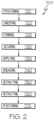
- the method 700 includes positioning 710 a composite ply 312 over a forming surface 310 of a forming tool 308.
- the positioning 710 includes applying the composite ply 312 directly on the forming surface 310 of the forming tool 308.
- the positioning 710 includes applying the composite ply 312 on top of previously applied composite material 325 over the forming surface 310 of the forming tool 308.
- the method 700 includes sweeping 720 a forming feature 104 into engagement with the composite ply 312 to yield a formed ply 318.
- the method 700 may further include forming 725 the composite ply 312 across the forming surface 310 of the forming tool 308.
- the forming 725 includes applying compaction force 144 to the composite ply 312.
- the forming 725 and the sweeping 720 occur simultaneously.
- the sweeping 720 and the forming 725 occur sequentially.
- the method 700 includes securing 730 the formed ply 318 relative to the forming tool 308.
- the securing 730 is performed with a clamping assembly 500 such that the securing 730 includes engaging a clamping assembly 500 with the formed ply 318.
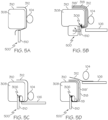
- FIGs. 5a-5g are simplified exemplary schematics of various examples of forming tool 308 and clamping assembly 500 used to perform method 700.
- Forming tool 308 may have a geometry of a stringer, spar, skin panel, or any other shape desired.
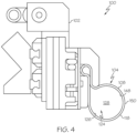
- Forming feature 104 illustrated in FIGs. 3 and 4 is shown in FIGs. 5a-5g without including detail of end effector 102, however, it is understood that the forming feature 104 in all 5a-5g illustrations is operatively associated with end effector 102 and forming apparatus 100 of FIGs. 6 and 7 .
- the clamping assembly 500 is movably engageable with the forming tool 308.
- the clamping assembly 500 may be coupled with forming apparatus 100.
- the clamping assembly 500 comprises a clamping member 510.
- the clamping member 510 may be rigid or flexible.
- the clamping assembly 500 comprises a bladder 118, see FIGs. 5c-5f .
- the bladder 118 may be inflatable such that the clamping assembly 500 may facilitate securing 730 the formed ply 318 relative to the forming tool 308 upon inflation of the bladder 118.
- the bladder 118 when inflated, impinges against the formed ply 318 and pushes against the forming tool 308.
- the clamping assembly 500 may include a bladder 118 located within recessed portion 306 of the forming tool 308.
- the clamping assembly 500 includes at least one of a cam assembly 512, a spring 514, a clamping member 510, and a bladder 118. Engagement of the clamping assembly may be automated such that control unit 136 controls when portions of the clamping assembly 500 move, inflate, engage, imping, retract, etc.
- the clamping assembly 500 utilizes compression load to secure the formed ply 318 between the clamping assembly 500 and forming tool 308.
- the securing 730 includes moving the clamping assembly 500 into engagement with the formed ply 318.
- the movement of the clamping assembly 500 may be automated by a control unit 136.
- the clamping assembly 500 is hydraulically moved into engagement with the formed ply 318.
- the clamping assembly 500 is hydraulically moved into engagement with the formed ply 318.
- the clamping assembly 500 is pivotably moved into engagement with the formed ply 318.
- the clamping assembly 500 is actuated into engagement with the formed ply 318.
- the clamping assembly 500 may be pneumatically inflated into engagement with the formed ply 318.
- the method 700 may further include retracting 750 the clamping assembly 500 from engagement with the formed ply 318.
- the forming tool 308 defines a recessed portion 306.
- the securing 730 may include engaging the clamping assembly 500 with the recessed portion 306 of the forming tool 308.
- the recessed portion 306 includes at least one bladder 118.
- the bladder 118 may be inflatable, and inflation of the bladder 118 may facilitate securing 730 of the formed ply 318 relative to the forming tool 308.
- the bladder 118 when inflated, impinges against the formed ply 318 and the forming tool 308 to secure the formed ply 318 while an additional composite ply 312 is swept into contour engagement with the forming tool 308 on top of the formed ply 318 and a previously formed ply 318', see FIG. 5B and FIG. 5D .
- the method 700 further includes engaging 740 a support member 106 with the formed ply 318.
- the support member 106 is operatively associated with the forming apparatus 100.
- the support member 106 may assist securing 730 the formed ply 318 relative to the forming tool 308.
- the support member 106 is operatively associated with the forming feature 104.
- the support member 106 includes a generally wedged-shaped member 106', see FIGs. 5e-5g .
- the method 700 may further include retracting 760 the support member 106.
- the method 700 further includes positioning 770 a second composite ply 312 over the formed ply 318.
- the steps outlined above for securing the formed ply 318 may repeat any number of desired times until a composite structure 314 is formed and ready for further processing.
- the method 700 includes sweeping 720 forming feature 104 into engagement with a second composite ply 312 over a formed ply 318 to sweep into contour engagement and yield a second formed ply 318 over the previously swept formed ply 318.
- the method 700 then may further include securing 730 the second formed ply 318 with clamping assembly 500 against the previously swept formed ply 318 and forming tool 308 while the forming feature 104 retracts for further sweeping 720.
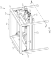
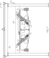
- the disclosed composite forming system 300 includes a composite forming apparatus 100, see FIGs. 6 and 7 .
- the composite forming apparatus 100 may be located within a frame 334, see FIG. 6 .
- the frame 334 is generally rectangular in shape.
- the frame 334 defines vertical axis 338, horizontal axis 340, and longitudinal axis 342.
- the frame 334 surrounds a carriage 336 having a shape that is generally the same as the frame 334 but is smaller such that the carriage 336 nests within the frame 334.
- the carriage 336 is movably connected to the frame 334 such that it may pivot or rotate along the vertical axis 338 and horizontal axis 340 to accommodate any specific geometry or configuration and achieve a best fit position.
- the composite forming apparatus 100 includes an end effector 102.
- the end effector 102 is movably connected to the carriage 336.
- the end effector 102 is movable via an actuator 110.
- the end effector 102 may include one or more sensor 140 configured to detect the location of a forming tool 308 along multiple axes including a vertical axis 338, horizonal axis 340, and longitudinal axis 342 for precise forming on a complex forming tool 308.
- the one or more sensor 140 may be in communication with a control unit 136.
- the control unit 136 is configured to receive data from the one or more sensor 140 and analyze that data to control movement of the end effector 102.
- the control unit 136 may utilize one or more numerical control program in conjunction with the data collected from the one or more sensor 140 to determine proper movement and placement of the end effector 102.
- the end effector 102 includes a forming feature 104.
- the forming feature 104 is a forming finger.
- forming feature 104 is a bladder 118.
- the bladder 118 is configured to passively follow forming tool 308 contours by applying consistent compaction force 144.
- Compaction force 144 may vary.
- Compaction force 144 may be up to 201bs per linear inch.
- the bladder 118 position, profile, or orientation may be manipulated to conform to any forming tool 308 geometry.
- the forming feature 104 includes, or takes the form of, a wiper.
- the wiper includes a wiper body and a wiper edge that extends from the wiper body.
- the wiper has any suitable geometry and/or stiffness depending on the application of the forming feature 104.
- the forming feature 104 includes, or takes the form of, a finger.
- the finger includes a finger body and a finger end that extends from the finger body.
- the finger has any suitable geometry and/or stiffness depending on the application of the forming feature 104.
- the forming feature 104 includes, or takes the form of, any one of various other forming members having various shapes, geometries, and/or configurations.
- the body 108 of the forming feature 104 may be a bead of material, such as a bead of silicone, rubber, and the like.
- the forming feature 104 is made of any material that is suitable for contact with the composite ply 312 in order to deform the composite ply 312 over the forming surface 310 and compact the composite ply 312 against the forming surface 310.
- the forming feature 104 is made of a material that is capable of withstanding generated by heat and transferring to the composite ply 312 when the forming feature 104 is in contact with the composite ply 312.
- the forming feature 104 is made of a material that is flexible.
- the forming feature 104 is made of natural or synthetic rubber. In one or more examples, the forming feature 104 is made of a fluoroelastomer (e.g., fluorocarbon-based synthetic rubber). In one or more examples, the forming feature 104 is made of silicone. Other materials for the forming feature 104 are also contemplated. In one or more examples, the forming feature 104 is made of a combination of various materials.
- the forming feature 104 is coupled to the end effector 102.
- the end effector 102 moves the forming feature 104 relative to a forming tool 308 to deform a composite ply 312 over a forming surface 310 of the forming tool 308.
- the composite forming apparatus 100 includes a clamping assembly 500.
- the clamping assembly 500 is movably engageable with the forming tool 308 for securing composite material 325 relative to the forming tool 308.
- the clamping assembly 500 includes a clamping member 510.
- the clamping member 510 may be rigid or flexible.
- the clamping member 510 is movable along the vertical axis 338.
- the clamping assembly 500 includes a bladder 118.
- the clamping assembly 500 may include more than one bladder 118.
- the bladder 118 may be inflatable. Inflation of the bladder 118 may facilitate securing the composite material 325 relative to the forming tool 308.
- the clamping assembly 500 includes a cam assembly 512 configured to secure the composite material 325 relative to the tool 308.
- the clamping assembly 500 includes a spring 514 configured to facilitate securing the composite material 325 relative to the tool 308.
- the clamping assembly 500 includes at least two or more of a bladder 118, a cam assembly 512, a spring 514, and a clamping member 510. Each portion of clamping assembly 500 may work in conjunction with ply support member 106 to secure composite material 325 relative to the forming tool 308.
- the forming tool 308 may define a recessed portion 306.
- the recessed portion 306 may include an inflatable bladder 118.
- the clamping assembly 500 is movably engageable with the recessed portion 306.
- the end effector 102 is one of a plurality of end effectors 145 extending along the longitudinal axis 342. Each end effector 102 of the plurality of end effectors 145 is coupled with an associated forming feature 104.
- the clamping assembly 500 is one of a plurality of clamping assemblies 500'.
- composite forming system 300 includes movement mechanism 302, the end effector 102, and the forming feature 104.
- the end effector 102 is coupled to the movement mechanism 302.
- the forming feature 104 is coupled to the end effector 102.
- the end effector 102 selectively positions and moves the forming feature 104 relative to the forming surface 310 of the forming tool 308 to apply the compaction force 144 to the composite ply 312.
- the movement mechanism 302 selectively positions and moves the end effector 102 relative to the forming surface 310 of the forming tool 308 to deform a portion of the composite ply 312 over a portion of the forming surface 310 using the forming feature 104.
- the clamping assembly 500 is movably engageable with the forming tool 308 and selectively secures the composite ply 312 relative to the forming tool 308.
- the movement mechanism 302 moves and selectively positions the end effector 102 along a plurality of movement axes, including a first axis 338, a second axis 340 that is perpendicular to the first axis 338, and a third axis 342 that is perpendicular to the first axis 338 and the second axis 340.
- the first axis 338 e.g., a vertical axis
- the second axis 340 e.g., a horizontal axis
- the third axis 342 e.g., a longitudinal axis
- the movement mechanism 302 includes a frame 334.
- the frame 334 is generally rectangular in shape.
- the frame 334 is an overhead frame and the forming tool 308 is positioned under the frame 334 during the layup operation.
- the frame 334 defines the first axis 338, the second axis 340, and the third axis 342.
- the movement mechanism 302 includes a carriage 336.
- the carriage 336 is coupled to the frame 334.
- the frame 334 surrounds the carriage 336.
- the carriage 336 has a shape that is generally the same as the frame 334 but is smaller such that the carriage 336 nests within the frame 334.
- the carriage 336 is movable relative to the frame 334. In one or more examples, the carriage 336 is pivotably movable and/or rotationally movable about the first axis 338, the second axis 340, and/or the third axis 342. In one or more examples, the carriage 336 is linearly movable along the first axis 338, the second axis 340, and/or the third axis 342. In one or more examples, the end effector 102 is coupled to the carriage 336. Movement of the carriage 336 moves and selectively positions the end effector 102 relative to the forming tool 308 to accommodate the geometry or configuration of the forming tool 308 and achieve a best fit position for the end effector 102.
- the end effector 102 is movable relative to the movement mechanism 302, such as relative to the carriage 336. In one or more examples, the end effector 102 is linearly movable relative to the movement mechanism 302. In one or more examples, the end effector 102 is rotationally movable relative to the movement mechanism 302.
- the composite forming apparatus 100 includes an actuator 110.
- the actuator 110 is coupled to, or forms a portion of, the end effector 102.
- the actuator 110 is, or includes, a linear actuator and the actuator 110 linearly moves the end effector 102 or the forming feature 104 relative to the carriage 336 to position the forming feature 104 into contact with the composite ply 312.
- the actuator 110 is, or includes, a rotary actuator and the actuator 110 rotationally moves the end effector 102 or the forming feature 104 relative to the carriage 336 to angularly orient the forming feature 104 relative to the forming tool 308 and position the forming feature 104 into contact with the composite ply 312.
- the actuator 110 is selectively controlled, for example, by the control unit 136, to control the position of the forming feature 104 and, thus, the compaction force 144 applied to the composite ply 312 by the forming feature 104.
- the actuator 110 is any one of various suitable types of controllable actuators.
- the actuator 110 is a pneumatic actuator.
- the actuator 110 is a hydraulic actuator.
- the actuator 110 is a mechanical actuator.
- the senor 140 is coupled to, or is in communication with, the actuator 110. In one or more examples, the sensor 140 detects at least one of a stroke position of the actuator 110 and a force acting on the actuator 110, which is used to determine the position of the forming feature 104 and to control the compaction force 144 for precise forming on the forming tool 308 having a complex geometry or surface contour.
- control unit 136 is, or includes, a numerical control (NC) unit.
- control unit 136 operates in accordance with a numerical control program and in conjunction with data (e.g., collected, received, and analyzed) from the sensor 140 to determine proper movement and position of the end effector 102 relative to the forming tool 308.
- data e.g., collected, received, and analyzed
- the composite forming system 300 includes the ply support member 106 that is movable relative to the forming tool 308 and relative to the composite forming composite forming apparatus 100 to support the portion of the composite ply 312, which extends beyond an edge 316 of the forming tool 308.
- the ply support member 106 is movably engageable relative to the forming tool 308 to guide securing the composite ply 312 relative to the forming tool 308.
- the ply support member 106 is coupled to the end effector 102. In these examples, the ply support member 106 is movable with the end effector 102, such as by the carriage 336, relative to the forming tool 308. In these examples, the ply support member 106 may also be movable relative to the end effector 102. In one or more examples, the ply support member 106 is coupled to the movement mechanism 302, such as to the carriage 336. In these examples, the ply support member 106 is movable relative to the carriage 336, relative to the end effector 102, and relative to the forming tool 308.
- movement mechanism 302 includes a drive mechanism dedicated to the ply support member 106 such that the ply support member 106 moves and is selectively positioned relative to the forming tool 308 independent of the carriage 336 and/or the end effector 102.
- the composite forming system 300 includes a second composite forming apparatus 200.
- the second composite forming apparatus 200 is coupled to the movement mechanism 302.
- the second composite forming apparatus 200 is spaced away from the composite forming composite forming apparatus 100.
- the movement mechanism 302 selectively positions and moves the second composite forming apparatus 200 to deform and compact the composite ply 312 over the forming surface 310.
- Examples of the second composite forming apparatus 200 are substantially the same as the examples of the composite forming apparatus 100 described herein above and illustrated in Figs. 1-9 .
- the second composite forming apparatus 200 includes a second end effector 202, and a second forming feature 204.
- Examples of the second end effector 202 and the second forming feature 204 are substantially the same as the examples of the end effector 102, and the forming feature 104 described herein above.
- the second forming feature 204 is coupled to the second end effector 202.
- the second end effector 202 moves the second forming feature 204 relative to the forming tool 308 to deform the composite ply 312 over the forming surface 310 of the forming tool 308.
- the clamping assembly 500 is movably engageable with the forming tool 308 to secure the composite ply 312 relative to the forming tool 308.
- the composite forming system 300 includes the second end effector 202, and the second forming feature 204.
- the second end effector 202 is coupled to the movement mechanism 302, such as to the carriage 336.
- the second forming feature 204 is coupled to the second end effector 202.
- the second end effector 202 selectively moves the second forming feature 204 relative to the forming surface 310 of the forming tool 308 to apply a second compaction force 244 to the composite ply 312.
- the movement mechanism 302 selectively moves the second end effector 202 relative to the forming surface 310 of the forming tool 308 to deform a second portion of the composite ply 312 over a second portion of the forming surface 310 using the second forming feature 204.
- the composite forming system 300 includes a second ply support member 206.
- the second ply support member 206 are substantially the same as the examples of the ply support member 106 described herein above and illustrated in Figs. 1-9 .
- the second ply support member 206 is movable relative to the forming tool 308.
- the second ply support member 206 is movable relative to the second end effector 202 and/or the second forming feature 204.
- the second ply support member 206 supports the second portion of the composite ply 312, which extends beyond a second edge 326 of the forming tool 308.
- the composite forming system 300 includes the stomp foot 324.
- the stomp foot 324 is coupled to the movement mechanism 302, such as to the carriage 336.
- the stomp foot 324 is movable relative to the movement mechanism 302 to press the composite ply 312 against the forming surface 310 of the forming tool 308 before and/or while the composite ply 312 is deformed over the forming surface 310 of the forming tool 308 using the forming feature 104 and/or the second forming feature 204.
- the stomp foot 324 is located between the composite forming apparatus 100 (e.g., the end effector 102) and the second composite forming apparatus 200 (e.g., the second end effector 202).
- the second forming feature 204 (e.g., the body 108) includes or takes the form of any forming member that is suitable for or that is capable of deforming the composite ply 312 over the forming surface 310 and compacting the composite ply 312 against the forming surface 310.
- the second forming feature 104 includes, or takes the form of, the bladder 118.
- the bladder 118 is inflatable.
- the bladder 118 is configured to move between at least two positions.
- the second forming feature 204 includes, or takes the form of, a wiper. In one or more examples, the second forming feature 204 includes, or takes the form of, a finger. In other examples, the second forming feature 204 includes, or takes the form of, any one of various other forming members having various shapes, geometries, and/or configurations.
- the body 108 of the second forming feature 204 may be a bead of material, such as a bead of silicone, rubber, and the like.
- the second forming feature 204 is made of any material that is suitable for contact with the composite ply 312 in order to deform the composite ply 312 over the forming surface 310 and compact the composite ply 312 against the forming surface 310.
- the second forming feature 204 is made of a material that is capable of withstanding heat and transferring heat when the second forming feature 204 is in contact with the composite ply 312.
- the second forming feature 204 is made of a material that is flexible.
- the second forming feature 204 is made of a fluoroelastomer.
- the second forming feature 204 is made of silicone.
- the second end effector 202 is movable relative to the movement mechanism 302, such as relative to the carriage 336. In one or more examples, the second end effector 202 is linearly movable relative to the movement mechanism 302. In one or more examples, the second end effector 202 is rotationally movable relative to the movement mechanism 302.
- the second composite forming apparatus 200 includes a second actuator 210.
- the second actuator 210 is coupled to, or forms a portion of, the second end effector 202.
- the second actuator 210 is, or includes, a linear actuator and the second actuator 210 linearly moves the second end effector 202 or the second forming feature 204 relative to the carriage 336 to position the second forming feature 204 into contact with the composite ply 312.
- the second actuator 210 is, or includes, a rotary actuator and the second actuator 210 rotationally moves the second end effector 202 or the second forming feature 204 relative to the carriage 336 to angularly orient the second forming feature 204 relative to the forming tool 308 and position the second forming feature 204 into contact with the composite ply 312.
- the second actuator 210 is selectively controlled, for example, by the control unit 136, to control the position of the second forming feature 204 and, thus, the second compaction force 244 applied to the composite ply 312 by the second forming feature 204.
- the composite forming system 300 includes the control unit 136.
- the control unit 136 may be coupled to (e.g., in communication with) the clamping assembly 500.
- the control unit 136 is configured to analyze data collected from one or more sensor 140 to determine movement within the system 300.
- the second composite forming apparatus 200 includes a second sensor 240.
- the second sensor 240 is a pressure sensor or a load cell that detects a force or a load applied to the second forming feature 204.
- the second sensor 240 is a position sensor that detects a relative position of the second forming feature 204.
- control unit 136 is coupled to (e.g., is in communication with) the second end effector 202 and the second sensor 240.
- the control unit 136 selectively controls movement of the second end effector 202 based on a second sensor signal 242 provided by the second sensor 240 to appropriately position the second forming feature 204 such that the second compaction force 244 is applied to the composite ply 312 using the second forming feature 204 at a constant magnitude.
- the composite forming system 300 includes a plurality of composite forming apparatus 100 (e.g., as illustrated in FIG. 6 ). In one or more examples, the composite forming system 300 includes a plurality of second composite forming apparatus 200 (e.g., as shown in Fig. 9 ). Each one of the plurality of composite forming apparatus 100 is coupled to the movement mechanism 302. Each one of the plurality of second composite forming apparatus 200 is coupled to the movement mechanism 302.
- the composite forming system 300 includes a plurality of end effectors 145 and a plurality of forming features 104.
- Each one of the plurality of end effectors 145 is coupled to the movement mechanism 302, such as to the carriage 336.
- Each one of the plurality of forming features 104 is coupled to a corresponding one of the plurality of end effectors 145.
- Each one of the plurality of end effectors 145 selectively positions and moves a corresponding one of the plurality of forming features 104 relative to the forming surface 310 of the forming tool 308 to apply the compaction force 144 to the composite ply 312.
- the movement mechanism 302 selectively positions and moves each one of the plurality of end effectors 145 relative to the forming surface 310 of the forming tool 308 to deform a portion of the composite ply 312 over a portion of the forming surface 310 using a corresponding one of the plurality of forming features 104.
- the composite forming system 300 includes a plurality of sensors 140. Each one of the plurality of sensors 140 detects at least one of a force applied to and a relative position of a corresponding one of the plurality of forming features 104.
- the control unit 136 is coupled to (e.g., is in communication with) each one of the plurality of end effectors 145 and each one of the plurality of sensors 140.
- the control unit 136 selectively controls movement of each one of the plurality of end effectors 145 based on the sensor signal 142 provided by a corresponding one of the plurality of sensors 140 to apply the compaction force 144 at a constant magnitude to the composite ply 312 using a corresponding one of the plurality of forming features 104.
- the plurality of forming features 104 form an interface surface 146 that is substantially continuous for contact with the composite ply 312. For example, each one of the plurality of forming features 104 abuts a directly adjacent one of the plurality of forming features 104 to form the substantially continuous interface surface 146 for contact with the composite ply 312.
- the composite forming system 300 includes a plurality of second end effectors 245 and a plurality of second forming features 204.
- Each one of the plurality of second end effectors 245 is coupled to the movement mechanism 302, such as to the carriage 336.
- Each one of the plurality of second forming features 204 is coupled to a corresponding one of the plurality of second end effectors 245.
- Each one of the plurality of second end effectors 245 selectively positions and moves a corresponding one of the plurality of second forming features 204 relative to the forming surface 310 of the forming tool 308 to apply the second compaction force 244 to the composite ply 312.
- the movement mechanism 302 selectively positions and moves each one of the plurality of second end effectors 245 relative to the forming surface 310 of the forming tool 308 to deform a portion of the composite ply 312 over a portion of the forming surface 310 using a corresponding one of the plurality of second forming features 204.
- the composite forming system 300 includes a plurality of second sensors 240.
- Each one of the plurality of second sensors 240 detects at least one of a force applied to and a relative position of a corresponding one of the plurality of second forming features 204.
- the control unit 136 is coupled to (e.g., is in communication with) each one of the plurality of second end effectors 245 and each one of the plurality of second sensors 240.
- the control unit 136 selectively controls movement of each one of the plurality of second end effectors 245 based on a second sensor signal 242 provided by a corresponding one of the plurality of second sensors 240 to apply the second compaction force 244 at a constant magnitude to the composite ply 312 using a corresponding one of the plurality of second forming features 204.
- the plurality of second forming features 204 form a second interface surface 246 that is substantially continuous for contact with the composite ply 312. For example, each one of the plurality of second forming feature 204 abuts a directly adjacent one of the plurality of second forming features 204 to form the substantially continuous second interface surface 246 for contact with the composite ply 312.
- the composite forming system 300 is one of a plurality of sub-systems of a larger automated composite manufacturing system. Each one of the plurality of sub-systems facilitates and corresponds to a different fabrication operation associated with the manufacture of the composite structure 314 (e.g., a composite part).
- the sub-systems of the automated composite manufacturing system are interlinked and cooperate to automate at least a portion of the fabrication process.
- the automated composite manufacturing system utilizes a plurality of semi-automated or fully automated sub-systems to perform ply-by-ply formation and compaction of individual composite plies 312 on the forming tool 308.
- ply-by-ply formation refers to sequential layup of a number of composite plies 312 on the forming tool 308 according to a predetermined sequence.
- layup refers to placement of the composite ply 312 on at least a portion of the forming tool 308, compaction of the composite ply 312 against the forming surface 310 of the forming tool 308, and deformation of at least a portion of the composite ply 312 over at least a portion of the forming surface 310.
- the number of composite plies 312 is compacted on the forming tool 308, such as individually after each composite ply 312 has been laid down or after more than one composite ply 312 had been laid down.
- a formed ply 318 becomes a previously formed ply 318' when a subsequent composite ply 312 is laid on top of formed ply 318 and is further processed to be a formed ply 318.
- the method 900 may utilize the above-described forming system 300, forming apparatus 100, and forming apparatus 200.
- the method 900 includes clamping 910, with a clamping assembly 500, an end of a formed ply 318 to a forming tool 308.
- the method 900 may further include clamping 910, with a clamping assembly 500, an end of a formed ply 318 to a previously formed ply 318' over the forming surface 310 of the forming tool 308.
- the clamping assembly 500 includes a clamping member 510.
- the clamping assembly 500 includes a bladder 118.
- the bladder 118 may be inflatable, and inflation of the bladder 118 may facilitate clamping 910 of the formed ply 318 relative to the forming tool 308. In one example, the bladder 118, when inflated, impinges against the formed ply 318 and the forming tool 308 to secure the formed ply 318.
- the forming tool 308 may define a recessed portion 306.
- the recessed portion 306 may include an inflatable bladder 118.
- the clamping assembly 500 is movably engageable with the recessed portion 306.
- the clamping 910 may include engaging the clamping assembly 500 with the recessed portion 306 of the forming tool 308.
- the recessed portion 306 includes at least one bladder 118.
- the method 900 further includes sweeping 920 a forming feature 104 into engagement with a composite ply 312 to form a composite ply 312 against the formed ply 318.
- the sweeping 920 may include applying compaction force 144 to the composite ply 312 such that it conforms to the forming tool 308.
- the method 900 further includes retracting 930 the clamping assembly 500 from formed ply 318.
- the retracting 930 may be pneumatically or hydraulically actuated, or may be pivotably achieved.
- the method 900 further includes sweeping 940 the composite ply 312 to an end against the formed ply 318 to form a second formed ply 318.
- the sweeping 940 may include applying compaction force 144 to the composite ply 312 such that it conforms to the forming tool 308.
- the method 900 further includes clamping 950 the end of the second formed ply 318 to the forming tool 308.
- the method 900 may repeat as many times needed for form the composite part 375 for further processing.
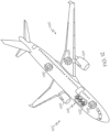
- examples of the composite forming apparatus 100, the composite forming system 300, the method 700, and the composite structure 314 may be related to, or used in the context of, an aircraft manufacturing and service method 1100, as shown in the flow diagram of FIG. 11 and an aircraft 1200, as schematically illustrated in FIG. 12 .
- the aircraft 1200 and/or the aircraft production and service method 1100 may utilize the composite structure 314 that is made using the composite forming apparatus 100 or the composite forming system 300, described herein and illustrated in FIGs. 1-9 , and/or according to the method 700.
- composite structures can be advantageous in the manufacture of aircraft to decrease the weight of the aircraft and provide longer service life for various components of the aircraft.
- layers of composite material are typically laid up on a tool.
- each layer of composite material includes a fiber sheet that is infused or pre-impregnated with a matrix material.
- the different layers of composite material may be laid up in different orientations, and different numbers of layers may be used depending on the performance requirements of the composite structure being manufactured. Due to size, geometry, and/or complexity of composite structure, layup of the layers of composite material may be more difficult or more labor intensive than desired.
- the examples of the composite forming apparatus 100, the composite forming system 300, and the method 700 improve upon production speed, conformity, and manufacturability of such composite structures.
- examples of the aircraft 1200 may include an airframe 1202 having the interior 1206.
- the aircraft 1200 also includes a plurality of high-level systems 1204.
- Examples of the high-level systems 1204 include one or more of a propulsion system 1208, an electrical system 1210, a hydraulic system 1212, and an environmental system 1214.
- the aircraft 1200 may include any number of other types of systems, such as a communications system, a flight control system, a guidance system, a weapons system, and the like.
- the composite structure 314 made using the composite forming apparatus 100 or the composite forming system 300 and/or according to the method 700 forms a component of the airframe 1202, such as a wing, a fuselage, a panel, a stringer, a spar, and the like.
- the method 1100 includes specification and design of the aircraft 1200 (block 1102) and material procurement (block 1104).
- component and subassembly manufacturing (block 1106) and system integration (block 1108) of the aircraft 1200 take place.
- the aircraft 1200 goes through certification and delivery (block 1110) to be placed in service (block 1112).
- Routine maintenance and service (block 1114) includes modification, reconfiguration, refurbishment, etc. of one or more systems of the aircraft 1200.
- a system integrator may include, without limitation, any number of spacecraft manufacturers and major-system subcontractors; a third party may include, without limitation, any number of vendors, subcontractors, and suppliers; and an operator may be an airline, leasing company, military entity, service organization, and so on.
- Examples of the composite forming apparatus 100, the composite forming system 300, and the method 700 shown and described herein may be employed during any one or more of the stages of the manufacturing and service method 1100 shown in the flow diagram illustrated by FIG. 11 .
- manufacture of the composite structure 314 in accordance with the method 700 and/or using the composite forming apparatus 100 or the composite forming system 300 may form a portion of component and subassembly manufacturing (block 1106) and/or system integration (block 1108).
- the composite structure 314 manufactured in accordance with the method 700 and/or using the composite forming apparatus 100 or the composite forming system 300 may be utilized in a manner similar to components or subassemblies prepared while the aircraft 1200 is in service (block 1112).
- the composite structure 314 manufactured in accordance with the method 700 and/or using the composite forming apparatus 100 or the composite forming system 300 may be utilized during system integration (block 1108) and certification and delivery (block 1110).
- manufacture of the composite structure 314 in accordance with the method 700 and/or using the composite forming apparatus 100 or the composite forming system 300 may be utilized, for example and without limitation, while the aircraft 1200 is in service (block 1112) and during maintenance and service (block 1114).
- the examples and principles disclosed herein may be applied to other industries, such as the automotive industry, the space industry, the construction industry, and other design and manufacturing industries. Accordingly, in addition to aircraft, the examples and principles disclosed herein may apply to structural component assemblies and systems and methods of making the same for other types of vehicles (e.g., land vehicles, marine vehicles, space vehicles, etc.) and stand-alone structures.
- vehicles e.g., land vehicles, marine vehicles, space vehicles, etc.
- example means that one or more feature, structure, element, component, characteristic, and/or operational step described in connection with the example is included in at least one aspect, embodiment, and/or implementation of the subject matter according to the present disclosure.
- the phrases “an example,” “another example,” “one or more examples,” and similar language throughout the present disclosure may, but do not necessarily, refer to the same example.
- the subject matter characterizing any one example may, but does not necessarily, include the subject matter characterizing any other example.
- subject matter characterizing any one example may be, but is not necessarily, combined with the subject matter characterizing any other example.
- a system, apparatus, device, structure, article, element, component, or hardware "configured to” perform a specified function is indeed capable of performing the specified function without any alteration, rather than merely having potential to perform the specified function after further modification.
- the system, apparatus, device, structure, article, element, component, or hardware "configured to” perform a specified function is specifically selected, created, implemented, utilized, programmed, and/or designed for the purpose of performing the specified function.
- "configured to” denotes existing characteristics of a system, apparatus, structure, article, element, component, or hardware that enable the system, apparatus, structure, article, element, component, or hardware to perform the specified function without further modification.
- a system, apparatus, device, structure, article, element, component, or hardware described as being “configured to” perform a particular function may additionally or alternatively be described as being “adapted to” and/or as being “operative to” perform that function.
- first,” “second,” “third,” etc. are used herein merely as labels, and are not intended to impose ordinal, positional, or hierarchical requirements on the items to which these terms refer. Moreover, reference to, e.g., a “second” item does not require or preclude the existence of, e.g., a "first” or lower-numbered item, and/or, e.g., a "third” or higher-numbered item.
Landscapes
- Engineering & Computer Science (AREA)
- Mechanical Engineering (AREA)
- Chemical & Material Sciences (AREA)
- Composite Materials (AREA)
- Textile Engineering (AREA)
- Robotics (AREA)
- Moulding By Coating Moulds (AREA)
Abstract
Description
- The present application relates to manufacturing of composite parts and, more particularly, to apparatus, methods, and systems for forming of composite parts.
- Formed composite structures are commonly used in applications where light weight and high strength are desired, such as in aircraft and vehicles. Often, these applications utilize contoured parts that must be formed and then cured. Conventional formation of composite structures, particularly relatively large composite structures or composite structures having a complex contour, requires extensive manual labor prior to curing. For example, composite fiber plies (e.g., pre-impregnated fiber plies or dry fabric) are laid by hand over a shaped forming tool or mandrel. The part is then cured, often by heating and pressure. Each composite ply adds volume to the laminate such that the resulting shape is complementary to the mandrel or matches the shape of the forming tool. However, manual layup of the fiber plies is time consuming and laborious.
- Some known composite manufacturing processes attempt to automate a portion of the formation operation. As an example, a drape forming process includes heating a laminate stack of pre-impregnated fiber plies ("composite charge") and forcing it around a mandrel with the use of a vacuum bag or rubber bladder. However, this method has achieved limited success on thick laminates or structures with more complex shapes. As another example, a compactor may be used to compress the composite charge against a tool surface during fabrication. However, this method often requires supplemental manual formation after compaction when the tool surface and resulting structure is contoured. Accordingly, while such methods may be effective at forming relatively small and thin composite structures or composite structures with relatively simple shapes, they may be inefficient when applied to forming large composite structures or composite structures with more complex shapes.
- Accordingly, those skilled in the art continue with research and development efforts in the field of composite manufacturing and, more particularly, to the manufacture of relatively large and/or relatively complex composite structures.
- Disclosed are methods for forming a composite part.
- In one example, the disclosed method includes positioning a composite ply over a forming surface of a forming tool, moving a forming feature into engagement with the composite ply to yield a formed ply, and, after the moving, securing the formed ply relative to the forming tool.
- Also disclosed are composite forming apparatus.
- In one example, the disclosed forming apparatus includes forming feature for deforming a composite ply over a forming surface of the forming tool and a clamping assembly for securing the composite ply relative to the forming tool.
- According to an aspect of the present disclosure a method for forming a composite part, the method comprises positioning a composite ply over a forming surface of a forming tool; sweeping a forming feature into engagement with the composite ply to yield a formed ply, the sweeping forms the composite ply to one of the forming tool and a previously formed ply on the forming tool; and securing the formed ply relative to the forming tool.
- Advantageously, the method is one wherein the securing comprises engaging a clamping assembly with the formed ply.
- Preferably, the method is one wherein the clamping assembly comprises a clamping member.
- Preferably, the method is one wherein the clamping assembly comprises a bladder.
- Preferably, the method is one wherein the bladder is inflatable, and wherein inflation of the bladder facilitates securing of the formed ply.
- Preferably, the method is one wherein the securing comprises moving the clamping assembly into engagement with the formed ply.
- Preferably, the method further comprises retracting the clamping assembly.
- Preferably, the method is one wherein the forming tool defines a recessed portion.
- Preferably, the method is one wherein the securing comprises engaging the clamping assembly with the recessed portion of the forming tool.
- Preferably, the method is one wherein the recessed portion comprises a bladder, and wherein inflation of the bladder facilitates securing of the formed ply.
- Preferably, the method further comprises forming the composite ply across the forming surface of the forming tool.
- Preferably, the method is one wherein the forming comprises applying compaction force to the composite ply.
- Preferably, the method is one wherein the forming and the sweeping occur simultaneously.
- Preferably, the method is one wherein the sweeping and the forming occur sequentially.
- Preferably, the method further comprises engaging a support member with the formed ply.
- Preferably, the method further comprises retracting the support member.
- Preferably, the method further comprises positioning a second composite ply over the formed ply.
- According to another aspect of the present disclosure, a composite forming apparatus comprises a forming feature for deforming a composite ply over a forming surface of a forming tool; and
a clamping assembly for securing the composite ply relative to the forming tool. - Advantageously, the composite forming apparatus is one wherein the clamping assembly comprises a clamping member.
- Preferably, the composite forming apparatus is one wherein the clamping assembly comprises a bladder.
- Preferably, the composite forming apparatus is one wherein the clamping assembly comprises a cam assembly.
- Preferably, the composite forming apparatus is one wherein the clamping assembly comprises a spring.
- Preferably, the composite forming apparatus is one wherein the forming tool defines a recessed portion, and wherein the clamping assembly is movably engageable with the recessed portion.
- Preferably, the composite forming apparatus further comprises a ply support member, the ply support member being movably engageable with the forming tool.
- Preferably, the composite forming apparatus further comprises an end effector, coupled to the forming feature, wherein the end effector moves the forming feature relative to the forming tool to deform the composite ply over the forming surface of the forming tool.
- According to yet another aspect of the present disclosure, a composite forming system comprises: a movement mechanism; an end effector that is coupled to the movement mechanism; a forming feature that is coupled to the end effector; and a clamping assembly that is movably engageable with a forming tool, wherein: the end effector selectively moves the forming feature relative to a forming surface of the forming tool to apply a compaction force to a composite ply; the movement mechanism selectively moves the end effector relative to the forming surface of the forming tool to deform a portion of the composite ply over a portion of the forming surface using the forming feature; and the clamping assembly selectively secures the composite ply relative to the forming tool.
- Advantageously, the composite forming system is one wherein the clamping assembly comprises a clamping member.
- Preferably, the composite forming system is one wherein the clamping assembly comprises a bladder.
- Preferably, the composite forming system is one wherein the clamping assembly comprises a cam assembly.
- Preferably, the composite forming system is one wherein the clamping assembly comprises a spring.
- Preferably, the composite forming system is one wherein the forming tool defines a recessed portion, and wherein the clamping assembly is movably engageable with the recessed portion.
- Preferably, the composite forming system further comprises a ply support member, the ply support member being movable relative to the forming tool.
- According to still another aspect of the present disclosure, a method for forming a composite part, the method comprises clamping, with a clamping assembly, an end of a formed ply to a forming tool; sweeping a forming feature into engagement with a composite ply to form a composite ply against the formed ply; retracting the clamping assembly from formed ply; sweeping the composite ply to an end against the formed ply to form a second formed ply; and clamping the end of the second formed ply to the forming tool.
- Advantageously, the method is one wherein the clamping assembly comprises a clamping member.
- Preferably, the method is one wherein the sweeping comprises applying compaction force to the composite ply.
- Preferably, the method is one wherein the forming tool comprises a previously formed ply between the formed ply and a forming tool surface.
- Preferably, the method is one wherein the clamping assembly comprises a bladder.
- Preferably, the method is one wherein the bladder is inflatable, and wherein inflation of the bladder facilitates clamping of the end of the formed ply.
- Preferably, the method is one wherein the forming tool defines a recessed portion.
- Preferably, the method is one wherein the clamping comprises engaging the clamping assembly with the recessed portion of the forming tool.
- Preferably, the method is one wherein the recessed portion comprises a bladder, and wherein inflation of the bladder facilitates clamping of the formed ply.
- Also disclosed are composite forming systems.
- In one example, the disclosed forming system includes a movement mechanism, an end effector that is coupled to the movement mechanism, a forming feature that is coupled to the end effector, and a clamping assembly that is movably engageable with a forming tool. The end effector selectively moves the forming feature relative to a forming surface of the forming tool to apply a compaction force to a composite ply. The movement mechanism selectively moves the end effector relative to the forming surface of the forming tool to deform a portion of the composite ply over a portion of the forming surface using the forming feature. The clamping assembly selectively secures the composite ply relative to the forming tool.
-
-
FIG. 1 is a schematic block diagram of an example of a composite forming system; -
FIG. 2 is a flow diagram of an example of a method for forming a composite; -
FIG. 3 is a schematic, elevational view of an example of a portion of the composite forming system; -
FIG. 4 is a schematic, elevational view of an example of a portion of the composite forming system; -
FIG. 5a is a schematic, elevational view of an example of a portion of the composite forming system; -
FIG. 5b is a schematic, elevational view of an example of a portion of the composite forming system; -
FIG. 5c is a schematic, elevational view of an example of a portion of the composite forming system; -
FIG. 5d is a schematic, elevational view of an example of a portion of the composite forming system; -
FIG. 5e is a schematic, elevational view of an example of a portion of the composite forming system; -
FIG. 5f is a schematic, elevational view of an example of a portion of the composite forming system; -
FIG. 5g is a schematic, elevational view of an example of a portion of the composite forming system; -
FIG. 6 is a schematic, perspective view of an example of a composite forming system; -
FIG. 7 is a schematic, elevational view of an example of the composite forming system; -
FIG. 8 is a schematic, perspective view of an example of a plurality of composite forming apparatus of the composite forming system; -
FIG. 9 is a schematic, perspective view of an example of a plurality of second composite forming apparatus of the composite forming system; -
FIG. 10 is a flow diagram of an example of a method for forming a composite; -
FIG. 11 is a flow diagram of an example of an aircraft manufacturing and service methodology; and -
Fig. 12 is a schematic illustration of an example of an aircraft. - Referring generally to
FIGs. 1-11 , by way of examples, the present disclosure is directed to a composite formingapparatus 100 and a composite formingsystem 300 for forming a composite on a forming tool during a composite manufacturing operation. Referring generally toFIGs. 1-11 , the present disclosure is also directed to amethod 700 for forming a composite on a forming tool during a composite manufacturing operation. In one or more examples, implementations of the composite formingapparatus 100, the composite formingsystem 300 and themethod 700 are utilized to individually lay down a number of composite plies on a forming tool to form a composite laminate on the formingtool 308, which is subsequently cured on the formingtool 308 to form acomposite structure 314. - Referring to
FIG. 1 , examples of composite formingapparatus 100 and composite formingsystem 300 enable automated, or at least partially automated, fabrication of acomposite laminate 328 on a formingtool 308. Thecomposite laminate 328 is then cured through the application of heat and/or pressure (e.g., using an oven or autoclave) to manufacture acomposite structure 314. More particularly, examples of the composite formingapparatus 100 and the composite formingsystem 300 enable automated, or at least partially automated, compaction and deformation of at least onecomposite ply 312 over a formingsurface 310 of the formingtool 308 for manufacture of thecomposite laminate 328. In other words, as used herein,composite ply 312 may be one ply or a stack of plies. - Automation of the ply formation process can provide a reduction in processing time, a reduction in labor and costs, and/or a reduction of process variations (e.g., human error) that may lead to undesired inconsistencies in the finished composite structure as compared to conventional composite fabrication. In particular, the
composite forming apparatus 100 and the composite formingsystem 300 enable, for example, ply-by-ply application (e.g., layup) of composite material to fabricate thecomposite laminate 328 on the formingtool 308. Following layup, thecomposite laminate 328 is cured, for example, on the formingtool 308, to form thecomposite structure 314. While the present disclosure is not limited to ply-by-ply forming, ply-by-ply forming facilitates fabrication of large composite structures, thick composite structures and/or composite structures with complex shapes. Ply-by-ply formation can also provide a reduction in buckling or wrinkling of plies within the composite structure as compared to conventional composite fabrication. - Referring to
FIGs. 1-10 , thecomposite forming apparatus 100 and composite formingsystem 300,FIGs. 6 and7 , operate to compact (e.g., apply pressure of force to) and deform (e.g., manipulate) thecomposite ply 312 on or over the formingsurface 310 of the formingtool 308. The composite formingapparatus 100 and composite formingsystem 300 operate to compact uniformly across non-uniform tool geometries by use of one ormore clamping assembly 500. Additionally, thecomposite forming apparatus 100 and composite formingsystem 300 may operate to transfer heat to a localized region of thecomposite ply 312 that is being compacted and deformed. - In one or more examples, the
composite ply 312 includes a single ply (e.g., one layer of thickness) of a composite material. In other examples, thecomposite ply 312 includes a plurality of plies (e.g., a plurality of layers of thickness) of the composite material. Throughout the present disclosure, the phrase "composite ply" refers to a number of plies or layers of the composite material, unless explicitly stated otherwise. Thecomposite ply 312 may also be referred to as a composite patch, a composite preform, or a composite charge. - The composite material may take the form of any one of various suitable types of composite material having any one of various ply angles or fiber orientations. In one or more examples, the composite material includes a fiber reinforcement, also referred to as a dry fabric. In these examples, the
composite laminate 328 is formed of a number ofcomposite plies 312 of the dry fiber reinforcement, which is infused with a matrix material (e.g., resin) following layup on the formingtool 308. In one or more examples, the composite material includes a fiber reinforcement that is pre-impregnated with the matrix material, also referred to as a pre-preg. In these examples, thecomposite laminate 328 is formed by laminating a number ofcomposite plies 312 of the pre-preg, such as multiple courses of unidirectional composite tape, which are pre-impregnated with a resin matrix. - In a particular example, the
composite ply 312 is a multi-axial non-crimp fabric that includes a thermoplastic veil and a knit stitch. Application of heat to thecomposite ply 312 immediately before and/or during compaction and deformation of thecomposite ply 312 softens the thermoplastic veil to improve deformability of thecomposite ply 312. Application of heat to thecomposite ply 312 immediately before and/or during compaction and deformation of thecomposite ply 312 also melts the knit stitch and increases the tackiness of the thermoplastic veil to improve adhesion of thecomposite ply 312. - As such, the
composite laminate 328 is formed on the formingtool 308 from a number of composite plies 312. Additionally, in one or more examples, thecomposite laminate 328 is cured on the formingtool 308 to form thecomposite structure 314. Accordingly, in one or more examples, the formingtool 308 is a dual-purpose tool, which serves as a layup tool (e.g., mandrel) and a cure tool. - The forming
tool 308 defines a shape of thecomposite laminate 328 formed on the formingtool 308 and, thus, a shape of thecomposite structure 314 cured on the formingtool 308. In an example, the formingsurface 310 corresponds to and defines a shape of an inner mold line (IML) surface thecomposite laminate 328 and, thus, thecomposite structure 314. In these examples, thecomposite forming apparatus 100 shapes an outer mold line (OML) surface of thecomposite laminate 328 and, thus, thecomposite structure 314. In another example, the formingsurface 310 corresponds to and defines a shape of the outer mold line (OML) surface of thecomposite laminate 328 and, thus, thecomposite structure 314. In these examples, thecomposite forming apparatus 100 shapes the inner mold line (IML) surface of thecomposite laminate 328 and, thus, thecomposite structure 314. - In one or more examples, the forming
tool 308 has any one of various shapes depending on thecomposite structure 314 being manufactured. As an example, the formingtool 308 is a stringer forming tool and thecomposite structure 314 is a composite stringer. As another example, the formingtool 308 is a spar forming tool and thecomposite structure 314 is a composite spar. As another example, the formingtool 308 is a panel forming tool and thecomposite structure 314 is a composite panel. The formingtool 308 may include various non-uniform geometric shapes including curves, joggles, cervices, and more. - Referring to
FIG. 2 , disclosed is amethod 700 for forming a composite part 375. Themethod 700 includes positioning 710 acomposite ply 312 over a formingsurface 310 of a formingtool 308. In one example, thepositioning 710 includes applying thecomposite ply 312 directly on the formingsurface 310 of the formingtool 308. In another example, thepositioning 710 includes applying thecomposite ply 312 on top of previously appliedcomposite material 325 over the formingsurface 310 of the formingtool 308. - Referring to
FIG. 2 , themethod 700 includes sweeping 720 a formingfeature 104 into engagement with thecomposite ply 312 to yield a formedply 318. Themethod 700 may further include forming 725 thecomposite ply 312 across the formingsurface 310 of the formingtool 308. In one example, the forming 725 includes applyingcompaction force 144 to thecomposite ply 312. In another example, the forming 725 and the sweeping 720 occur simultaneously. In yet another example, the sweeping 720 and the forming 725 occur sequentially. - After the sweeping 720, the
method 700 includes securing 730 the formedply 318 relative to the formingtool 308. In one example, the securing 730 is performed with a clampingassembly 500 such that the securing 730 includes engaging a clampingassembly 500 with the formedply 318. -
FIGs. 5a-5g are simplified exemplary schematics of various examples of formingtool 308 and clampingassembly 500 used to performmethod 700. Formingtool 308 may have a geometry of a stringer, spar, skin panel, or any other shape desired. Formingfeature 104 illustrated inFIGs. 3 and4 is shown inFIGs. 5a-5g without including detail ofend effector 102, however, it is understood that the formingfeature 104 in all 5a-5g illustrations is operatively associated withend effector 102 and formingapparatus 100 ofFIGs. 6 and7 . - Referring to
FIGs. 5a-5g , in one or more examples, the clampingassembly 500 is movably engageable with the formingtool 308. The clampingassembly 500 may be coupled with formingapparatus 100. In one example, the clampingassembly 500 comprises a clampingmember 510. The clampingmember 510 may be rigid or flexible. In one example, the clampingassembly 500 comprises abladder 118, seeFIGs. 5c-5f . Thebladder 118 may be inflatable such that the clampingassembly 500 may facilitate securing 730 the formedply 318 relative to the formingtool 308 upon inflation of thebladder 118. In one example, thebladder 118, when inflated, impinges against the formedply 318 and pushes against the formingtool 308. Further, as illustrated inFIGs. 5c and 5d , the clampingassembly 500 may include abladder 118 located within recessedportion 306 of the formingtool 308. - In one or more examples, the clamping
assembly 500 includes at least one of acam assembly 512, aspring 514, a clampingmember 510, and abladder 118. Engagement of the clamping assembly may be automated such thatcontrol unit 136 controls when portions of the clampingassembly 500 move, inflate, engage, imping, retract, etc. The clampingassembly 500 utilizes compression load to secure the formedply 318 between the clampingassembly 500 and formingtool 308. - In one or more examples, the securing 730 includes moving the clamping
assembly 500 into engagement with the formedply 318. The movement of the clampingassembly 500 may be automated by acontrol unit 136. In one example, the clampingassembly 500 is hydraulically moved into engagement with the formedply 318. In another example, the clampingassembly 500 is hydraulically moved into engagement with the formedply 318. In another example, the clampingassembly 500 is pivotably moved into engagement with the formedply 318. In yet another example, the clampingassembly 500 is actuated into engagement with the formedply 318. Further, the clampingassembly 500 may be pneumatically inflated into engagement with the formedply 318. Themethod 700 may further include retracting 750 the clampingassembly 500 from engagement with the formedply 318. - Referring to
FIGs. 5b-5g , in one or more examples, the formingtool 308 defines a recessedportion 306. The securing 730 may include engaging the clampingassembly 500 with the recessedportion 306 of the formingtool 308. In one example, the recessedportion 306 includes at least onebladder 118. Thebladder 118 may be inflatable, and inflation of thebladder 118 may facilitate securing 730 of the formedply 318 relative to the formingtool 308. In one example, thebladder 118, when inflated, impinges against the formedply 318 and the formingtool 308 to secure the formedply 318 while an additionalcomposite ply 312 is swept into contour engagement with the formingtool 308 on top of the formedply 318 and a previously formed ply 318', seeFIG. 5B and FIG. 5D . - Referring back to
FIG. 2 , in one or more examples, themethod 700 further includes engaging 740 asupport member 106 with the formedply 318. In one example, thesupport member 106 is operatively associated with the formingapparatus 100. Thesupport member 106 may assist securing 730 the formedply 318 relative to the formingtool 308. In one example, thesupport member 106 is operatively associated with the formingfeature 104. In another example, thesupport member 106 includes a generally wedged-shaped member 106', seeFIGs. 5e-5g . Themethod 700 may further include retracting 760 thesupport member 106. - Still referring to
FIG. 2 , in one or more examples, themethod 700 further includes positioning 770 a secondcomposite ply 312 over the formedply 318. The steps outlined above for securing the formedply 318 may repeat any number of desired times until acomposite structure 314 is formed and ready for further processing. In one example, themethod 700 includes sweeping 720 formingfeature 104 into engagement with a secondcomposite ply 312 over a formedply 318 to sweep into contour engagement and yield a second formedply 318 over the previously swept formedply 318. Themethod 700 then may further include securing 730 the second formedply 318 with clampingassembly 500 against the previously swept formedply 318 and formingtool 308 while the formingfeature 104 retracts for further sweeping 720. - Referring to
FIG. 1 , the disclosed composite formingsystem 300 includes a composite formingapparatus 100, seeFIGs. 6 and7 . The composite formingapparatus 100 may be located within aframe 334, seeFIG. 6 . In an example, theframe 334 is generally rectangular in shape. Theframe 334 definesvertical axis 338,horizontal axis 340, andlongitudinal axis 342. Theframe 334 surrounds acarriage 336 having a shape that is generally the same as theframe 334 but is smaller such that thecarriage 336 nests within theframe 334. In an example, thecarriage 336 is movably connected to theframe 334 such that it may pivot or rotate along thevertical axis 338 andhorizontal axis 340 to accommodate any specific geometry or configuration and achieve a best fit position. - The composite forming
apparatus 100 includes anend effector 102. Theend effector 102 is movably connected to thecarriage 336. In an example, theend effector 102 is movable via anactuator 110. Theend effector 102 may include one ormore sensor 140 configured to detect the location of a formingtool 308 along multiple axes including avertical axis 338,horizonal axis 340, andlongitudinal axis 342 for precise forming on a complex formingtool 308. The one ormore sensor 140 may be in communication with acontrol unit 136. Thecontrol unit 136 is configured to receive data from the one ormore sensor 140 and analyze that data to control movement of theend effector 102. Thecontrol unit 136 may utilize one or more numerical control program in conjunction with the data collected from the one ormore sensor 140 to determine proper movement and placement of theend effector 102. - Referring to
FIG. 4 , an enlarged view fromFIG. 7 , theend effector 102 includes a formingfeature 104. In an example, the formingfeature 104 is a forming finger. In an example, formingfeature 104 is abladder 118. Thebladder 118 is configured to passively follow formingtool 308 contours by applyingconsistent compaction force 144.Compaction force 144 may vary. In an example,Compaction force 144 may be up to 201bs per linear inch. Thebladder 118 position, profile, or orientation may be manipulated to conform to any formingtool 308 geometry. - In one or more examples, the forming
feature 104 includes, or takes the form of, a wiper. The wiper includes a wiper body and a wiper edge that extends from the wiper body. The wiper has any suitable geometry and/or stiffness depending on the application of the formingfeature 104. - In one or more examples, the forming
feature 104 includes, or takes the form of, a finger. The finger includes a finger body and a finger end that extends from the finger body. The finger has any suitable geometry and/or stiffness depending on the application of the formingfeature 104. - In other examples, the forming
feature 104 includes, or takes the form of, any one of various other forming members having various shapes, geometries, and/or configurations. For example, thebody 108 of the formingfeature 104 may be a bead of material, such as a bead of silicone, rubber, and the like. - Referring to
FIG. 1 , in one or more examples, the formingfeature 104 is made of any material that is suitable for contact with thecomposite ply 312 in order to deform thecomposite ply 312 over the formingsurface 310 and compact thecomposite ply 312 against the formingsurface 310. In one or more examples, the formingfeature 104 is made of a material that is capable of withstanding generated by heat and transferring to thecomposite ply 312 when the formingfeature 104 is in contact with thecomposite ply 312. In one or more examples, the formingfeature 104 is made of a material that is flexible. - In one or more examples, the forming
feature 104 is made of natural or synthetic rubber. In one or more examples, the formingfeature 104 is made of a fluoroelastomer (e.g., fluorocarbon-based synthetic rubber). In one or more examples, the formingfeature 104 is made of silicone. Other materials for the formingfeature 104 are also contemplated. In one or more examples, the formingfeature 104 is made of a combination of various materials. - The forming
feature 104 is coupled to theend effector 102. Theend effector 102 moves the formingfeature 104 relative to a formingtool 308 to deform acomposite ply 312 over a formingsurface 310 of the formingtool 308. - Referring to
FIGs. 5a-5g , thecomposite forming apparatus 100 includes a clampingassembly 500. The clampingassembly 500 is movably engageable with the formingtool 308 for securingcomposite material 325 relative to the formingtool 308. In one example, the clampingassembly 500 includes a clampingmember 510. The clampingmember 510 may be rigid or flexible. In one example, the clampingmember 510 is movable along thevertical axis 338. - In one or more examples, the clamping
assembly 500 includes abladder 118. The clampingassembly 500 may include more than onebladder 118. Thebladder 118 may be inflatable. Inflation of thebladder 118 may facilitate securing thecomposite material 325 relative to the formingtool 308. - In one example, referring to
FIG. 5g , the clampingassembly 500 includes acam assembly 512 configured to secure thecomposite material 325 relative to thetool 308. In another example, the clampingassembly 500 includes aspring 514 configured to facilitate securing thecomposite material 325 relative to thetool 308. In yet another example, the clampingassembly 500 includes at least two or more of abladder 118, acam assembly 512, aspring 514, and a clampingmember 510. Each portion of clampingassembly 500 may work in conjunction withply support member 106 to securecomposite material 325 relative to the formingtool 308. - Referring to
FIGs. 5b-5g , the formingtool 308 may define a recessedportion 306. The recessedportion 306 may include aninflatable bladder 118. In one example, the clampingassembly 500 is movably engageable with the recessedportion 306. - Referring to
FIG. 8 , theend effector 102 is one of a plurality of end effectors 145 extending along thelongitudinal axis 342. Eachend effector 102 of the plurality of end effectors 145 is coupled with an associated formingfeature 104. In one example, the clampingassembly 500 is one of a plurality of clamping assemblies 500'. - Referring to
Figs. 1-9 , in one or more examples, composite formingsystem 300 includesmovement mechanism 302, theend effector 102, and the formingfeature 104. Theend effector 102 is coupled to themovement mechanism 302. The formingfeature 104 is coupled to theend effector 102. Theend effector 102 selectively positions and moves the formingfeature 104 relative to the formingsurface 310 of the formingtool 308 to apply thecompaction force 144 to thecomposite ply 312. Themovement mechanism 302 selectively positions and moves theend effector 102 relative to the formingsurface 310 of the formingtool 308 to deform a portion of thecomposite ply 312 over a portion of the formingsurface 310 using the formingfeature 104. The clampingassembly 500 is movably engageable with the formingtool 308 and selectively secures thecomposite ply 312 relative to the formingtool 308. - Referring to
FIGs. 1-9 , in one or more examples, themovement mechanism 302 moves and selectively positions theend effector 102 along a plurality of movement axes, including afirst axis 338, asecond axis 340 that is perpendicular to thefirst axis 338, and athird axis 342 that is perpendicular to thefirst axis 338 and thesecond axis 340. In the illustrative examples, the first axis 338 (e.g., a vertical axis) is approximately vertical and the second axis 340 (e.g., a horizontal axis) and the third axis 342 (e.g., a longitudinal axis) are approximately horizontal. - In one or more example, the
movement mechanism 302 includes aframe 334. In one or more examples, theframe 334 is generally rectangular in shape. In one or more examples, theframe 334 is an overhead frame and the formingtool 308 is positioned under theframe 334 during the layup operation. Generally, theframe 334 defines thefirst axis 338, thesecond axis 340, and thethird axis 342. In one or more examples, themovement mechanism 302 includes acarriage 336. Thecarriage 336 is coupled to theframe 334. Theframe 334 surrounds thecarriage 336. In one or more examples, thecarriage 336 has a shape that is generally the same as theframe 334 but is smaller such that thecarriage 336 nests within theframe 334. In one or more examples, thecarriage 336 is movable relative to theframe 334. In one or more examples, thecarriage 336 is pivotably movable and/or rotationally movable about thefirst axis 338, thesecond axis 340, and/or thethird axis 342. In one or more examples, thecarriage 336 is linearly movable along thefirst axis 338, thesecond axis 340, and/or thethird axis 342. In one or more examples, theend effector 102 is coupled to thecarriage 336. Movement of thecarriage 336 moves and selectively positions theend effector 102 relative to the formingtool 308 to accommodate the geometry or configuration of the formingtool 308 and achieve a best fit position for theend effector 102. - Referring to
FIG. 6 , in one or more examples, theend effector 102 is movable relative to themovement mechanism 302, such as relative to thecarriage 336. In one or more examples, theend effector 102 is linearly movable relative to themovement mechanism 302. In one or more examples, theend effector 102 is rotationally movable relative to themovement mechanism 302. - In one or more examples, the
composite forming apparatus 100 includes anactuator 110. Theactuator 110 is coupled to, or forms a portion of, theend effector 102. In one or more examples, theactuator 110 is, or includes, a linear actuator and theactuator 110 linearly moves theend effector 102 or the formingfeature 104 relative to thecarriage 336 to position the formingfeature 104 into contact with thecomposite ply 312. In one or more examples, theactuator 110 is, or includes, a rotary actuator and theactuator 110 rotationally moves theend effector 102 or the formingfeature 104 relative to thecarriage 336 to angularly orient the formingfeature 104 relative to the formingtool 308 and position the formingfeature 104 into contact with thecomposite ply 312. In one or more examples, theactuator 110 is selectively controlled, for example, by thecontrol unit 136, to control the position of the formingfeature 104 and, thus, thecompaction force 144 applied to thecomposite ply 312 by the formingfeature 104. - In one or more examples, the
actuator 110 is any one of various suitable types of controllable actuators. In an example, theactuator 110 is a pneumatic actuator. In an example, theactuator 110 is a hydraulic actuator. In an example, theactuator 110 is a mechanical actuator. - In one or more examples, the
sensor 140 is coupled to, or is in communication with, theactuator 110. In one or more examples, thesensor 140 detects at least one of a stroke position of theactuator 110 and a force acting on theactuator 110, which is used to determine the position of the formingfeature 104 and to control thecompaction force 144 for precise forming on the formingtool 308 having a complex geometry or surface contour. - In one or more examples, the
control unit 136 is, or includes, a numerical control (NC) unit. In these examples, thecontrol unit 136 operates in accordance with a numerical control program and in conjunction with data (e.g., collected, received, and analyzed) from thesensor 140 to determine proper movement and position of theend effector 102 relative to the formingtool 308. - Referring to
FIG. 1 , in one or more examples, the composite formingsystem 300 includes theply support member 106 that is movable relative to the formingtool 308 and relative to the composite forming composite formingapparatus 100 to support the portion of thecomposite ply 312, which extends beyond anedge 316 of the formingtool 308. In one example, theply support member 106 is movably engageable relative to the formingtool 308 to guide securing thecomposite ply 312 relative to the formingtool 308. - In one or more examples, the
ply support member 106 is coupled to theend effector 102. In these examples, theply support member 106 is movable with theend effector 102, such as by thecarriage 336, relative to the formingtool 308. In these examples, theply support member 106 may also be movable relative to theend effector 102. In one or more examples, theply support member 106 is coupled to themovement mechanism 302, such as to thecarriage 336. In these examples, theply support member 106 is movable relative to thecarriage 336, relative to theend effector 102, and relative to the formingtool 308. In one or more examples,movement mechanism 302 includes a drive mechanism dedicated to theply support member 106 such that theply support member 106 moves and is selectively positioned relative to the formingtool 308 independent of thecarriage 336 and/or theend effector 102. - Referring to
FIG. 1 , in one or more examples, the composite formingsystem 300 includes a secondcomposite forming apparatus 200. The secondcomposite forming apparatus 200 is coupled to themovement mechanism 302. The secondcomposite forming apparatus 200 is spaced away from the composite forming composite formingapparatus 100. Themovement mechanism 302 selectively positions and moves the secondcomposite forming apparatus 200 to deform and compact thecomposite ply 312 over the formingsurface 310. - Examples of the second
composite forming apparatus 200 are substantially the same as the examples of the composite formingapparatus 100 described herein above and illustrated inFigs. 1-9 . In one or more examples, the secondcomposite forming apparatus 200 includes asecond end effector 202, and a second formingfeature 204. - Examples of the
second end effector 202 and the second formingfeature 204 are substantially the same as the examples of theend effector 102, and the formingfeature 104 described herein above. The second formingfeature 204 is coupled to thesecond end effector 202. Thesecond end effector 202 moves the second formingfeature 204 relative to the formingtool 308 to deform thecomposite ply 312 over the formingsurface 310 of the formingtool 308. The clampingassembly 500 is movably engageable with the formingtool 308 to secure thecomposite ply 312 relative to the formingtool 308. - Referring still to
FIGs. 1 and6-9 , in one or more examples, the composite formingsystem 300 includes thesecond end effector 202, and the second formingfeature 204. Thesecond end effector 202 is coupled to themovement mechanism 302, such as to thecarriage 336. The second formingfeature 204 is coupled to thesecond end effector 202. Thesecond end effector 202 selectively moves the second formingfeature 204 relative to the formingsurface 310 of the formingtool 308 to apply asecond compaction force 244 to thecomposite ply 312. Themovement mechanism 302 selectively moves thesecond end effector 202 relative to the formingsurface 310 of the formingtool 308 to deform a second portion of thecomposite ply 312 over a second portion of the formingsurface 310 using the second formingfeature 204. - Referring to
Figs. 1 and10 , in one or more examples, the composite formingsystem 300 includes a secondply support member 206. Examples of the secondply support member 206 are substantially the same as the examples of theply support member 106 described herein above and illustrated inFigs. 1-9 . In one or more examples, the secondply support member 206 is movable relative to the formingtool 308. In one or more examples, the secondply support member 206 is movable relative to thesecond end effector 202 and/or the second formingfeature 204. The secondply support member 206 supports the second portion of thecomposite ply 312, which extends beyond asecond edge 326 of the formingtool 308. - Referring to
FIGs. 6 and7 , in one or more examples, the composite formingsystem 300 includes thestomp foot 324. In one or more examples, thestomp foot 324 is coupled to themovement mechanism 302, such as to thecarriage 336. Thestomp foot 324 is movable relative to themovement mechanism 302 to press thecomposite ply 312 against the formingsurface 310 of the formingtool 308 before and/or while thecomposite ply 312 is deformed over the formingsurface 310 of the formingtool 308 using the formingfeature 104 and/or the second formingfeature 204. - Referring to
FIGs. 6 and7 , in one or more examples, thestomp foot 324 is located between the composite forming apparatus 100 (e.g., the end effector 102) and the second composite forming apparatus 200 (e.g., the second end effector 202). - Referring to
FIGs. 1 and9 , in one or more examples, the second forming feature 204 (e.g., the body 108) includes or takes the form of any forming member that is suitable for or that is capable of deforming thecomposite ply 312 over the formingsurface 310 and compacting thecomposite ply 312 against the formingsurface 310. - Referring to
FIG. 1 , in one or more examples, the second formingfeature 104 includes, or takes the form of, thebladder 118. Thebladder 118 is inflatable. Thebladder 118 is configured to move between at least two positions. - Referring still to
FIG. 1 , in one or more examples, the second formingfeature 204 includes, or takes the form of, a wiper. In one or more examples, the second formingfeature 204 includes, or takes the form of, a finger. In other examples, the second formingfeature 204 includes, or takes the form of, any one of various other forming members having various shapes, geometries, and/or configurations. For example, thebody 108 of the second formingfeature 204 may be a bead of material, such as a bead of silicone, rubber, and the like. - Referring to
FIG. 1 , in one or more examples, the second formingfeature 204 is made of any material that is suitable for contact with thecomposite ply 312 in order to deform thecomposite ply 312 over the formingsurface 310 and compact thecomposite ply 312 against the formingsurface 310. In one or more examples, the second formingfeature 204 is made of a material that is capable of withstanding heat and transferring heat when the second formingfeature 204 is in contact with thecomposite ply 312. In one or more examples, the second formingfeature 204 is made of a material that is flexible. In one or more examples, the second formingfeature 204 is made of a fluoroelastomer. In one or more examples, the second formingfeature 204 is made of silicone. - Referring to
FIGs. 7 and9 , in one or more examples, thesecond end effector 202 is movable relative to themovement mechanism 302, such as relative to thecarriage 336. In one or more examples, thesecond end effector 202 is linearly movable relative to themovement mechanism 302. In one or more examples, thesecond end effector 202 is rotationally movable relative to themovement mechanism 302. - In one or more examples, the second
composite forming apparatus 200 includes asecond actuator 210. Thesecond actuator 210 is coupled to, or forms a portion of, thesecond end effector 202. In one or more examples, thesecond actuator 210 is, or includes, a linear actuator and thesecond actuator 210 linearly moves thesecond end effector 202 or the second formingfeature 204 relative to thecarriage 336 to position the second formingfeature 204 into contact with thecomposite ply 312. In one or more examples, thesecond actuator 210 is, or includes, a rotary actuator and thesecond actuator 210 rotationally moves thesecond end effector 202 or the second formingfeature 204 relative to thecarriage 336 to angularly orient the second formingfeature 204 relative to the formingtool 308 and position the second formingfeature 204 into contact with thecomposite ply 312. In one or more examples, thesecond actuator 210 is selectively controlled, for example, by thecontrol unit 136, to control the position of the second formingfeature 204 and, thus, thesecond compaction force 244 applied to thecomposite ply 312 by the second formingfeature 204. - Referring to
FIG. 1 , in one or more examples, the composite formingsystem 300 includes thecontrol unit 136. Thecontrol unit 136 may be coupled to (e.g., in communication with) the clampingassembly 500. Thecontrol unit 136 is configured to analyze data collected from one ormore sensor 140 to determine movement within thesystem 300. - Referring still to
FIG. 1 , in one or more examples, the secondcomposite forming apparatus 200 includes asecond sensor 240. In one or more examples, thesecond sensor 240 is a pressure sensor or a load cell that detects a force or a load applied to the second formingfeature 204. In one or more examples, thesecond sensor 240 is a position sensor that detects a relative position of the second formingfeature 204. - In one or more examples, the
control unit 136 is coupled to (e.g., is in communication with) thesecond end effector 202 and thesecond sensor 240. Thecontrol unit 136 selectively controls movement of thesecond end effector 202 based on asecond sensor signal 242 provided by thesecond sensor 240 to appropriately position the second formingfeature 204 such that thesecond compaction force 244 is applied to thecomposite ply 312 using the second formingfeature 204 at a constant magnitude. - Referring to
FIGs. 1 ,8 , and9 , in one or more examples, the composite formingsystem 300 includes a plurality of composite forming apparatus 100 (e.g., as illustrated inFIG. 6 ). In one or more examples, the composite formingsystem 300 includes a plurality of second composite forming apparatus 200 (e.g., as shown inFig. 9 ). Each one of the plurality of composite formingapparatus 100 is coupled to themovement mechanism 302. Each one of the plurality of secondcomposite forming apparatus 200 is coupled to themovement mechanism 302. - Referring to
FIG. 8 , in one or more examples, the composite formingsystem 300 includes a plurality of end effectors 145 and a plurality of forming features 104. Each one of the plurality of end effectors 145 is coupled to themovement mechanism 302, such as to thecarriage 336. Each one of the plurality of formingfeatures 104 is coupled to a corresponding one of the plurality of end effectors 145. Each one of the plurality of end effectors 145 selectively positions and moves a corresponding one of the plurality of formingfeatures 104 relative to the formingsurface 310 of the formingtool 308 to apply thecompaction force 144 to thecomposite ply 312. Themovement mechanism 302 selectively positions and moves each one of the plurality of end effectors 145 relative to the formingsurface 310 of the formingtool 308 to deform a portion of thecomposite ply 312 over a portion of the formingsurface 310 using a corresponding one of the plurality of forming features 104. - In one or more examples, the composite forming
system 300 includes a plurality ofsensors 140. Each one of the plurality ofsensors 140 detects at least one of a force applied to and a relative position of a corresponding one of the plurality of forming features 104. In one or more examples, thecontrol unit 136 is coupled to (e.g., is in communication with) each one of the plurality of end effectors 145 and each one of the plurality ofsensors 140. Thecontrol unit 136 selectively controls movement of each one of the plurality of end effectors 145 based on thesensor signal 142 provided by a corresponding one of the plurality ofsensors 140 to apply thecompaction force 144 at a constant magnitude to thecomposite ply 312 using a corresponding one of the plurality of forming features 104. - In one or more examples, the plurality of forming
features 104 form aninterface surface 146 that is substantially continuous for contact with thecomposite ply 312. For example, each one of the plurality of formingfeatures 104 abuts a directly adjacent one of the plurality of formingfeatures 104 to form the substantiallycontinuous interface surface 146 for contact with thecomposite ply 312. - Referring to
FIG. 9 , in one or more examples, the composite formingsystem 300 includes a plurality of second end effectors 245 and a plurality of second forming features 204. Each one of the plurality of second end effectors 245 is coupled to themovement mechanism 302, such as to thecarriage 336. Each one of the plurality of second formingfeatures 204 is coupled to a corresponding one of the plurality of second end effectors 245. Each one of the plurality of second end effectors 245 selectively positions and moves a corresponding one of the plurality of second formingfeatures 204 relative to the formingsurface 310 of the formingtool 308 to apply thesecond compaction force 244 to thecomposite ply 312. Themovement mechanism 302 selectively positions and moves each one of the plurality of second end effectors 245 relative to the formingsurface 310 of the formingtool 308 to deform a portion of thecomposite ply 312 over a portion of the formingsurface 310 using a corresponding one of the plurality of second forming features 204. - In one or more examples, the composite forming
system 300 includes a plurality ofsecond sensors 240. Each one of the plurality ofsecond sensors 240 detects at least one of a force applied to and a relative position of a corresponding one of the plurality of second forming features 204. In one or more examples, thecontrol unit 136 is coupled to (e.g., is in communication with) each one of the plurality of second end effectors 245 and each one of the plurality ofsecond sensors 240. Thecontrol unit 136 selectively controls movement of each one of the plurality of second end effectors 245 based on asecond sensor signal 242 provided by a corresponding one of the plurality ofsecond sensors 240 to apply thesecond compaction force 244 at a constant magnitude to thecomposite ply 312 using a corresponding one of the plurality of second forming features 204. - In one or more examples, the plurality of second forming
features 204 form asecond interface surface 246 that is substantially continuous for contact with thecomposite ply 312. For example, each one of the plurality of second formingfeature 204 abuts a directly adjacent one of the plurality of second formingfeatures 204 to form the substantially continuoussecond interface surface 246 for contact with thecomposite ply 312. - In one or more examples, the composite forming
system 300 is one of a plurality of sub-systems of a larger automated composite manufacturing system. Each one of the plurality of sub-systems facilitates and corresponds to a different fabrication operation associated with the manufacture of the composite structure 314 (e.g., a composite part). The sub-systems of the automated composite manufacturing system are interlinked and cooperate to automate at least a portion of the fabrication process. - For example, the automated composite manufacturing system utilizes a plurality of semi-automated or fully automated sub-systems to perform ply-by-ply formation and compaction of individual composite plies 312 on the forming
tool 308. For the purpose of the present disclosure, ply-by-ply formation refers to sequential layup of a number ofcomposite plies 312 on the formingtool 308 according to a predetermined sequence. For the purpose of the present disclosure, layup refers to placement of thecomposite ply 312 on at least a portion of the formingtool 308, compaction of thecomposite ply 312 against the formingsurface 310 of the formingtool 308, and deformation of at least a portion of thecomposite ply 312 over at least a portion of the formingsurface 310. During or subsequent to layup, the number ofcomposite plies 312 is compacted on the formingtool 308, such as individually after eachcomposite ply 312 has been laid down or after more than onecomposite ply 312 had been laid down. After acomposite ply 312 is laid and formed, it becomes a formedply 318. A formedply 318 becomes a previously formed ply 318' when a subsequentcomposite ply 312 is laid on top of formedply 318 and is further processed to be a formedply 318. - Referring to
FIG. 10 , disclosed is amethod 900 for forming a composite part 375. Themethod 900 may utilize the above-described formingsystem 300, formingapparatus 100, and formingapparatus 200. Themethod 900 includes clamping 910, with a clampingassembly 500, an end of a formedply 318 to a formingtool 308. Themethod 900 may further include clamping 910, with a clampingassembly 500, an end of a formedply 318 to a previously formed ply 318' over the formingsurface 310 of the formingtool 308. In one example, the clampingassembly 500 includes a clampingmember 510. In another example, the clampingassembly 500 includes abladder 118. Thebladder 118 may be inflatable, and inflation of thebladder 118 may facilitate clamping 910 of the formedply 318 relative to the formingtool 308. In one example, thebladder 118, when inflated, impinges against the formedply 318 and the formingtool 308 to secure the formedply 318. - In one example, referring to
FIGs. 5b-5g , the formingtool 308 may define a recessedportion 306. The recessedportion 306 may include aninflatable bladder 118. In one example, the clampingassembly 500 is movably engageable with the recessedportion 306. The clamping 910 may include engaging the clampingassembly 500 with the recessedportion 306 of the formingtool 308. In one example, the recessedportion 306 includes at least onebladder 118. - The
method 900 further includes sweeping 920 a formingfeature 104 into engagement with acomposite ply 312 to form acomposite ply 312 against the formedply 318. The sweeping 920 may include applyingcompaction force 144 to thecomposite ply 312 such that it conforms to the formingtool 308. - The
method 900 further includes retracting 930 the clampingassembly 500 from formedply 318. The retracting 930 may be pneumatically or hydraulically actuated, or may be pivotably achieved. - The
method 900 further includes sweeping 940 thecomposite ply 312 to an end against the formedply 318 to form a second formedply 318. The sweeping 940 may include applyingcompaction force 144 to thecomposite ply 312 such that it conforms to the formingtool 308. - The
method 900 further includes clamping 950 the end of the second formedply 318 to the formingtool 308. Themethod 900 may repeat as many times needed for form the composite part 375 for further processing. - Referring now to
FIGs. 11 and12 , examples of the composite formingapparatus 100, the composite formingsystem 300, themethod 700, and thecomposite structure 314 may be related to, or used in the context of, an aircraft manufacturing andservice method 1100, as shown in the flow diagram ofFIG. 11 and an aircraft 1200, as schematically illustrated inFIG. 12 . For example, the aircraft 1200 and/or the aircraft production andservice method 1100 may utilize thecomposite structure 314 that is made using thecomposite forming apparatus 100 or the composite formingsystem 300, described herein and illustrated inFIGs. 1-9 , and/or according to themethod 700. - The present disclosure recognizes that composite structures can be advantageous in the manufacture of aircraft to decrease the weight of the aircraft and provide longer service life for various components of the aircraft. In manufacturing composite structures, layers of composite material are typically laid up on a tool. Often, each layer of composite material includes a fiber sheet that is infused or pre-impregnated with a matrix material. The different layers of composite material may be laid up in different orientations, and different numbers of layers may be used depending on the performance requirements of the composite structure being manufactured. Due to size, geometry, and/or complexity of composite structure, layup of the layers of composite material may be more difficult or more labor intensive than desired. The examples of the composite forming
apparatus 100, the composite formingsystem 300, and themethod 700 improve upon production speed, conformity, and manufacturability of such composite structures. - Referring to
FIG. 12 , examples of the aircraft 1200 may include an airframe 1202 having the interior 1206. The aircraft 1200 also includes a plurality of high-level systems 1204. Examples of the high-level systems 1204 include one or more of a propulsion system 1208, an electrical system 1210, a hydraulic system 1212, and an environmental system 1214. In other examples, the aircraft 1200 may include any number of other types of systems, such as a communications system, a flight control system, a guidance system, a weapons system, and the like. In one or more examples, thecomposite structure 314 made using thecomposite forming apparatus 100 or the composite formingsystem 300 and/or according to themethod 700 forms a component of the airframe 1202, such as a wing, a fuselage, a panel, a stringer, a spar, and the like. - Referring to
FIG. 11 , during pre-production, themethod 1100 includes specification and design of the aircraft 1200 (block 1102) and material procurement (block 1104). During production of the aircraft 1200, component and subassembly manufacturing (block 1106) and system integration (block 1108) of the aircraft 1200 take place. Thereafter, the aircraft 1200 goes through certification and delivery (block 1110) to be placed in service (block 1112). Routine maintenance and service (block 1114) includes modification, reconfiguration, refurbishment, etc. of one or more systems of the aircraft 1200. - Each of the processes of the
method 1100 illustrated inFIG. 11 may be performed or carried out by a system integrator, a third party, and/or an operator (e.g., a customer). For the purposes of this description, a system integrator may include, without limitation, any number of spacecraft manufacturers and major-system subcontractors; a third party may include, without limitation, any number of vendors, subcontractors, and suppliers; and an operator may be an airline, leasing company, military entity, service organization, and so on. - Examples of the composite forming
apparatus 100, the composite formingsystem 300, and themethod 700 shown and described herein may be employed during any one or more of the stages of the manufacturing andservice method 1100 shown in the flow diagram illustrated byFIG. 11 . In an example, manufacture of thecomposite structure 314 in accordance with themethod 700 and/or using thecomposite forming apparatus 100 or the composite formingsystem 300 may form a portion of component and subassembly manufacturing (block 1106) and/or system integration (block 1108). Further, thecomposite structure 314 manufactured in accordance with themethod 700 and/or using thecomposite forming apparatus 100 or the composite formingsystem 300 may be utilized in a manner similar to components or subassemblies prepared while the aircraft 1200 is in service (block 1112). Also, thecomposite structure 314 manufactured in accordance with themethod 700 and/or using thecomposite forming apparatus 100 or the composite formingsystem 300 may be utilized during system integration (block 1108) and certification and delivery (block 1110). Similarly, manufacture of thecomposite structure 314 in accordance with themethod 700 and/or using thecomposite forming apparatus 100 or the composite formingsystem 300 may be utilized, for example and without limitation, while the aircraft 1200 is in service (block 1112) and during maintenance and service (block 1114). - Also provided herein are the following clauses, which relate to:
- Clause 1. A method (700) for forming a composite part (375), the method (700) comprising:
- positioning (710) a composite ply (312) over a forming surface (310) of a forming tool (308);
- sweeping (720) a forming feature (104) into engagement with the composite ply (312) to yield a formed ply (318), the sweeping 720 forms the composite ply (312) to one of the forming tool (308) and a previously formed ply (318') on the forming tool (308); and
- securing (730) the formed ply (318) relative to the forming tool (308).
- Clause 2. The method (700) of Clause 1, wherein the securing (730) comprising engaging a clamping assembly (500) with the formed ply (318).
- Clause 3. The method (700) of Clause 2, wherein the clamping assembly (500) comprising a clamping member (510).
- Clause 4. The method according to Clause 2 or 3, wherein the clamping assembly (500) comprising a bladder (118).
-
Clause 5. The method according to Clause 4, wherein the bladder (118) is inflatable, and wherein inflation of the bladder (118) facilitates securing (730) of the formed ply (318). - Clause 6. The method (700) according to any one of Clauses 2 to 5, wherein the securing (730) comprising moving the clamping assembly (500) into engagement with the formed ply (318).
- Clause 7. The method (700) according to any one of Clauses 2 to 6, further comprising retracting (750) the clamping assembly (500).
- Clause 8. The method (700) according to any one of Clauses 2 to 7, wherein the forming tool (308) defines a recessed portion (306).
- Clause 9. The method (700) of Clause 8, wherein the securing (730) comprising engaging the clamping assembly (500) with the recessed portion (306) of the forming tool (308).
- Clause 10. The method (700) according to Clause 8 or 9, wherein the recessed portion (306) comprising a bladder (118), and wherein inflation of the bladder (118) facilitates securing (730) of the formed ply (318).
- Clause 11. The method (700) according to any one of Clauses 2 to 10, further comprising forming (725) the composite ply (312) across the forming surface (310) of the forming tool (308).
- Clause 12. The method (700) of Clause 11, wherein the forming (725) comprising applying compaction force (144) to the composite ply (312).
- Clause 13. The method (700) according to Clause 11 or 12, wherein the forming (725) and the sweeping (720) occur simultaneously.
- Clause 14. The method (700) according to any one of Clauses 11 to 13, wherein the sweeping (720) and the forming (725) occur sequentially.
- Clause 15. The method (700) according to any one of Clauses 1 to 14, further comprising engaging (740) a support member (106) with the formed ply (318).
- Clause 16. The method (700) of Clause 15, further comprising retracting (760) the support member (106).
- Clause 17. The method (700) according to any one of Clauses 1 to 16, further comprising positioning (770) a second composite ply (312) over the formed ply (318).
- Clause 18. A composite forming apparatus (100) comprising a forming feature (104) for deforming a composite ply (312) over a forming surface (310) of a forming tool (308); and a clamping assembly (500) for securing the composite ply (312) relative to the forming tool (308).
- Clause 19. The composite forming apparatus (100) of Clause 18, wherein the clamping assembly (500) comprising a clamping member (510).
- Clause 20. The composite forming apparatus (100) according to Clause 18 or 19, wherein the clamping assembly (500) comprising a bladder (118).
- Clause 21. The composite forming apparatus (100) according to any one of Clauses 18 to 20, wherein the clamping assembly (500) comprising a cam assembly (512).
- Clause 22. The composite forming apparatus (100) according to any one of Clauses 18 to 21, wherein the clamping assembly (500) comprising a spring (514).
- Clause 23. The composite forming apparatus (100) according to any one of Clauses 18 to 22, wherein the forming tool (308) defines a recessed portion (306), and wherein the clamping assembly (500) is movably engageable with the recessed portion (306).
- Clause 24. The composite forming apparatus (100) according to any one of Clauses 18 to 23, further comprising a ply support member (106), the ply support member (106) being movably engageable with the forming tool (308).
- Clause 25. The composite forming apparatus (100) according to any one of Clauses 18 to 24, further comprising: an end effector (102), coupled to the forming feature (104), wherein the end effector (102) moves the forming feature (104) relative to the forming tool (308) to deform the composite ply (312) over the forming surface (310) of the forming tool (308).
- Clause 26. A composite forming system (300) comprising:
- a movement mechanism (302);
- an end effector (102) that is coupled to the movement mechanism (302);
- a forming feature (104) that is coupled to the end effector (102); and
- a clamping assembly (500) that is movably engageable with a forming tool (308), wherein:
- the end effector (102) selectively moves the forming feature (104) relative to a forming surface (310) of the forming tool (308) to apply a compaction force (144) to a composite ply (312);
- the movement mechanism (302) selectively moves the end effector (102) relative to the forming surface (310) of the forming tool (308) to deform a portion of the composite ply (312) over a portion of the forming surface (310) using the forming feature (104); and
- the clamping assembly (500) selectively secures the composite ply (312) relative to the forming tool (308).
- Clause 27. The composite forming system (300) according to Clause 26, wherein the clamping assembly (500) comprises a clamping member (510).
- Clause 28. The composite forming system (300) according to Clause 26 or 27, wherein the clamping assembly (500) comprises a bladder (118).
- Clause 29. The composite forming system (300) according to any one of clauses 26 to 28, wherein the clamping assembly (500) comprises a cam assembly (512).
- Clause 30. The composite forming system (300) according to any one of clauses 26 to 29, wherein the clamping assembly (500) comprises a spring (514).
- Clause 31. The composite forming system (300) according to any one of clauses 26 to 30, wherein the forming tool (308) defines a recessed portion (306), and wherein the clamping assembly (500) is movably engageable with the recessed portion (306).
- Clause 32. The composite forming system (300) according to any one of clauses 26 to 31, further comprising a ply support member (106), the ply support member (106) being movable relative to the forming tool (308).
- Clause 33. A method (900) for forming a composite part (375), the method (900) comprising:
- clamping (910), with a clamping assembly (500), an end of a formed ply (318) to a forming tool (308);
- sweeping (920) a forming feature (104) into engagement with a composite ply (312) to form a composite ply (312) against the formed ply (318);
- retracting (930) the clamping assembly (500) from formed ply (318);
- sweeping (940) the composite ply (312) to an end against the formed ply (318) to form a second formed ply (318); and
- clamping (950) the end of the second formed ply (318) to the forming tool (308).
- Clause 34. The method (900) according to Clause 33, wherein the clamping assembly (500) comprises a clamping member (510).
- Clause 35. The method (900) according to Clause 33 or 34, wherein the sweeping (920) comprises applying compaction force (144) to the composite ply (312).
- Clause 36. The method (900) according to any one of Clauses 33 to 35, wherein the forming tool (308) comprises a previously formed ply (318') between the formed ply (318) and a forming tool surface (310).
- Clause 37. The method (900) according to any one of Clauses 33 to 36, wherein the clamping assembly (500) comprises a bladder (118).
- Clause 38. The method (900) according to Clause 37, wherein the bladder (118) is inflatable, and wherein inflation of the bladder (118) facilitates clamping (910) of the end of the formed ply (318).
- Clause 39. The method (900) according to any one of Clauses 33 to 38, wherein the forming tool (308) defines a recessed portion (306).
- Clause 40. The method (900) of Clause 39, wherein the clamping (910) comprises engaging the clamping assembly (500) with the recessed portion (306) of the forming tool (308).
- Clause 41. The method (900) according to Clause 39 or 40, wherein the recessed portion (306) comprises a bladder (118), and wherein inflation of the bladder (118) facilitates clamping (910) of the formed ply (318).
- Although an aerospace example is shown, the examples and principles disclosed herein may be applied to other industries, such as the automotive industry, the space industry, the construction industry, and other design and manufacturing industries. Accordingly, in addition to aircraft, the examples and principles disclosed herein may apply to structural component assemblies and systems and methods of making the same for other types of vehicles (e.g., land vehicles, marine vehicles, space vehicles, etc.) and stand-alone structures.
- The preceding detailed description refers to the accompanying drawings, which illustrate specific examples described by the present disclosure. Other examples having different structures and operations do not depart from the scope of the present disclosure. Like reference numerals may refer to the same feature, element, or component in the different drawings. Throughout the present disclosure, any one of a plurality of items may be referred to individually as the item and a plurality of items may be referred to collectively as the items and may be referred to with like reference numerals. Moreover, as used herein, a feature, element, component, or step preceded with the word "a" or "an" should be understood as not excluding a plurality of features, elements, components, or steps, unless such exclusion is explicitly recited.
- Illustrative, non-exhaustive examples, which may be, but are not necessarily, claimed, of the subject matter according to the present disclosure are provided above. Reference herein to "example" means that one or more feature, structure, element, component, characteristic, and/or operational step described in connection with the example is included in at least one aspect, embodiment, and/or implementation of the subject matter according to the present disclosure. Thus, the phrases "an example," "another example," "one or more examples," and similar language throughout the present disclosure may, but do not necessarily, refer to the same example. Further, the subject matter characterizing any one example may, but does not necessarily, include the subject matter characterizing any other example. Moreover, the subject matter characterizing any one example may be, but is not necessarily, combined with the subject matter characterizing any other example.
- As used herein, a system, apparatus, device, structure, article, element, component, or hardware "configured to" perform a specified function is indeed capable of performing the specified function without any alteration, rather than merely having potential to perform the specified function after further modification. In other words, the system, apparatus, device, structure, article, element, component, or hardware "configured to" perform a specified function is specifically selected, created, implemented, utilized, programmed, and/or designed for the purpose of performing the specified function. As used herein, "configured to" denotes existing characteristics of a system, apparatus, structure, article, element, component, or hardware that enable the system, apparatus, structure, article, element, component, or hardware to perform the specified function without further modification. For purposes of this disclosure, a system, apparatus, device, structure, article, element, component, or hardware described as being "configured to" perform a particular function may additionally or alternatively be described as being "adapted to" and/or as being "operative to" perform that function.
- Unless otherwise indicated, the terms "first," "second," "third," etc. are used herein merely as labels, and are not intended to impose ordinal, positional, or hierarchical requirements on the items to which these terms refer. Moreover, reference to, e.g., a "second" item does not require or preclude the existence of, e.g., a "first" or lower-numbered item, and/or, e.g., a "third" or higher-numbered item.
- The described features, advantages, and characteristics of one example may be combined in any suitable manner in one or more other examples. One skilled in the relevant art will recognize that the examples described herein may be practiced without one or more of the specific features or advantages of a particular example. In other instances, additional features and advantages may be recognized in certain examples that may not be present in all examples. Furthermore, although various examples of the composite forming
apparatus 100, the composite formingsystem 300, themethod 700, and thecomposite structure 314 have been shown and described, modifications may occur to those skilled in the art upon reading the specification. The present application includes such modifications and is limited only by the scope of the claims.
Claims (15)
- A method (700) for forming a composite part (375), the method (700) comprising:positioning (710) a composite ply (312) over a forming surface (310) of a forming tool (308);sweeping (720) a forming feature (104) into engagement with the composite ply (312) to yield a formed ply (318), the sweeping 720 forms the composite ply (312) to one of the forming tool (308) and a previously formed ply (318') on the forming tool (308); andsecuring (730) the formed ply (318) relative to the forming tool (308).
- The method (700) of Claim 1, wherein the securing (730) comprising engaging a clamping assembly (500) with the formed ply (318).
- The method (700) of Claim 2, wherein the clamping assembly (500) comprising a clamping member (510).
- The method according to Claim 2 or 3, wherein the clamping assembly (500) comprising a bladder (118).
- The method (700) according to any one of Claims 2 to 4, wherein the securing (730) comprising moving the clamping assembly (500) into engagement with the formed ply (318).
- The method (700) according to any one of Claims 2 to 5, wherein the forming tool (308) defines a recessed portion (306).
- The method (700) according to any one of Claims 2 to 6, further comprising forming (725) the composite ply (312) across the forming surface (310) of the forming tool (308).
- The method (700) according to any one of Claims 1 to 7, further comprising engaging (740) a support member (106) with the formed ply (318).
- The method (700) according to any one of Claims 1 to 8, further comprising positioning (770) a second composite ply (312) over the formed ply (318).
- A composite forming apparatus (100) comprising:a forming feature (104) for deforming a composite ply (312) over a forming surface (310) of a forming tool (308); anda clamping assembly (500) for securing the composite ply (312) relative to the forming tool (308).
- The composite forming apparatus (100) of Claim 10, wherein the clamping assembly (500) comprising a clamping member (510).
- The composite forming apparatus (100) according to Claim 10 or 11, wherein the clamping assembly (500) comprising a bladder (118).
- The composite forming apparatus (100) according to any one of Claims 10 to 12, wherein the forming tool (308) defines a recessed portion (306), and wherein the clamping assembly (500) is movably engageable with the recessed portion (306).
- The composite forming apparatus (100) according to any one of Claims 10 to 13, further comprising a ply support member (106), the ply support member (106) being movably engageable with the forming tool (308).
- A composite forming system (300) comprising:a movement mechanism (302);an end effector (102) that is coupled to the movement mechanism (302);a forming feature (104) that is coupled to the end effector (102); anda clamping assembly (500) that is movably engageable with a forming tool (308), wherein:the end effector (102) selectively moves the forming feature (104) relative to a forming surface (310) of the forming tool (308) to apply a compaction force (144) to a composite ply (312);the movement mechanism (302) selectively moves the end effector (102) relative to the forming surface (310) of the forming tool (308) to deform a portion of the composite ply (312) over a portion of the forming surface (310) using the forming feature (104); andthe clamping assembly (500) selectively secures the composite ply (312) relative to the forming tool (308).
Applications Claiming Priority (1)
| Application Number | Priority Date | Filing Date | Title |
|---|---|---|---|
| US17/460,605 US12138864B2 (en) | 2021-08-30 | 2021-08-30 | Forming apparatus, methods, and systems |
Publications (2)
| Publication Number | Publication Date |
|---|---|
| EP4140683A1 true EP4140683A1 (en) | 2023-03-01 |
| EP4140683B1 EP4140683B1 (en) | 2026-05-06 |
Family
ID=82016513
Family Applications (1)
| Application Number | Title | Priority Date | Filing Date |
|---|---|---|---|
| EP22178132.1A Active EP4140683B1 (en) | 2021-08-30 | 2022-06-09 | Forming apparatus, methods, and systems |
Country Status (4)
| Country | Link |
|---|---|
| US (2) | US12138864B2 (en) |
| EP (1) | EP4140683B1 (en) |
| JP (1) | JP2023035908A (en) |
| CN (1) | CN115891208A (en) |
Families Citing this family (1)
| Publication number | Priority date | Publication date | Assignee | Title |
|---|---|---|---|---|
| US20250269616A1 (en) * | 2024-02-23 | 2025-08-28 | The Boeing Company | Composite forming |
Citations (4)
| Publication number | Priority date | Publication date | Assignee | Title |
|---|---|---|---|---|
| JP2000229353A (en) * | 1999-02-12 | 2000-08-22 | Hitachi Ltd | Laminate bending equipment |
| US20110085911A1 (en) * | 2009-10-12 | 2011-04-14 | Vestas Wind Systems A/S | Fixing device |
| EP2783840A1 (en) * | 2013-03-27 | 2014-10-01 | Alstom Renovables España, S.L. | Methods of manufacturing composite structures and moulds for manufacturing composite structures |
| US20150273771A1 (en) * | 2012-10-22 | 2015-10-01 | Wobben Properties Gmbh | Method and apparatus for producing preforms for the production of a rotor blade |
Family Cites Families (53)
| Publication number | Priority date | Publication date | Assignee | Title |
|---|---|---|---|---|
| US5591369A (en) | 1991-04-05 | 1997-01-07 | The Boeing Company | Method and apparatus for consolidating organic matrix composites using induction heating |
| US5728309A (en) | 1991-04-05 | 1998-03-17 | The Boeing Company | Method for achieving thermal uniformity in induction processing of organic matrix composites or metals |
| US5793024A (en) | 1991-04-05 | 1998-08-11 | The Boeing Company | Bonding using induction heating |
| US5705794A (en) | 1991-10-15 | 1998-01-06 | The Boeing Company | Combined heating cycles to improve efficiency in inductive heating operations |
| US6087640A (en) | 1991-10-15 | 2000-07-11 | The Boeing Company | Forming parts with complex curvature |
| US5914064A (en) | 1991-10-15 | 1999-06-22 | The Boeing Company | Combined cycle for forming and annealing |
| US5387098A (en) | 1992-04-23 | 1995-02-07 | The Boeing Company | Flexible reusable mandrels |
| US6180932B1 (en) | 1998-12-30 | 2001-01-30 | The Boeing Company | Brazing honeycomb panels with controlled net tooling pressure |
| US6653608B1 (en) | 2001-10-24 | 2003-11-25 | The Boeing Company | Oxidation protected susceptor |
| US6566635B1 (en) | 2002-03-08 | 2003-05-20 | The Boeing Company | Smart susceptor having a geometrically complex molding surface |
| US6528771B1 (en) | 2002-03-08 | 2003-03-04 | The Boeing Company | System and method for controlling an induction heating process |
| US6814916B2 (en) | 2002-08-30 | 2004-11-09 | The Boeing Company | Forming method for composites |
| US7118370B2 (en) | 2002-08-30 | 2006-10-10 | The Boeing Company | Composite spar drape forming machine |
| US6884975B2 (en) | 2002-11-12 | 2005-04-26 | The Boeing Company | Localized stress relief by induction heating |
| US7137182B2 (en) | 2002-11-22 | 2006-11-21 | The Boeing Company | Parallel configuration composite material fabricator |
| US8336596B2 (en) | 2002-11-22 | 2012-12-25 | The Boeing Company | Composite lamination using array of parallel material dispensing heads |
| US6884976B2 (en) | 2002-11-27 | 2005-04-26 | The Boeing Company | Induction heating for localized joining of structural members |
| US6747253B1 (en) | 2003-05-07 | 2004-06-08 | The Boeing Company | Method and apparatus for induction heat treatment of structural members |
| US6914225B2 (en) | 2003-06-18 | 2005-07-05 | The Boeing Company | Apparatus and methods for single sheet forming using induction heating |
| US7622066B2 (en) * | 2004-07-26 | 2009-11-24 | The Boeing Company | Methods and systems for manufacturing composite parts with female tools |
| US8372327B2 (en) | 2007-09-13 | 2013-02-12 | The Boeing Company | Method for resin transfer molding composite parts |
| US8480823B1 (en) | 2007-09-13 | 2013-07-09 | The Boeing Company | Induction forming of metal components with integral heat treatment |
| US8017059B2 (en) | 2007-09-13 | 2011-09-13 | The Boeing Company | Composite fabrication apparatus and method |
| US8884201B2 (en) | 2008-09-15 | 2014-11-11 | The Boeing Company | Systems and methods for fabrication of thermoplastic components |
| US9469408B1 (en) | 2009-09-03 | 2016-10-18 | The Boeing Company | Ice protection system and method |
| US8383998B1 (en) | 2009-11-02 | 2013-02-26 | The Boeing Company | Tooling inserts for laminated tooling |
| US8410409B1 (en) | 2009-12-22 | 2013-04-02 | The Boeing Company | Flexible coil segments for high efficiency inductors |
| US10000026B2 (en) | 2011-04-08 | 2018-06-19 | The Boeing Company | Composite induction consolidation apparatus and method |
| US9586362B2 (en) | 2011-05-17 | 2017-03-07 | The Boeing Company | Thermoplastic welding apparatus and method |
| US8980029B1 (en) | 2011-05-17 | 2015-03-17 | The Boeing Company | Doubler repair apparatus and method |
| US8808490B2 (en) | 2011-08-04 | 2014-08-19 | The Boeing Company | Methods for laminating composites |
| US9820339B2 (en) | 2011-09-29 | 2017-11-14 | The Boeing Company | Induction heating using induction coils in series-parallel circuits |
| US8963058B2 (en) | 2011-11-28 | 2015-02-24 | The Boeing Company | System and method of adjusting the equilibrium temperature of an inductively-heated susceptor |
| US10058950B1 (en) | 2012-10-25 | 2018-08-28 | The Boeing Company | Systems and methods for use in induction welding |
| US9510398B1 (en) | 2012-10-29 | 2016-11-29 | The Boeing Company | Induction heating apparatus |
| US9314975B1 (en) | 2013-04-25 | 2016-04-19 | The Boeing Company | High rate fabrication of compression molded components |
| US9635714B2 (en) | 2013-05-06 | 2017-04-25 | The Boeing Company | Incremental sheet forming for fabrication of cold sprayed smart susceptor |
| US9635715B1 (en) | 2013-05-08 | 2017-04-25 | The Boeing Company | Smart susceptor radiant heater |
| US9868249B2 (en) | 2013-07-15 | 2018-01-16 | The Boeing Company | Induction welding system |
| US9610654B1 (en) | 2013-09-09 | 2017-04-04 | The Boeing Company | Conformable induction coils for induction joining |
| US10018175B2 (en) | 2015-01-05 | 2018-07-10 | The Boeing Company | Induction consolidation for wind blade fabrication |
| US9663247B2 (en) | 2015-02-27 | 2017-05-30 | The Boeing Company | Systems, methods, and vacuum chucks for transferring flexible elongate bodies |
| US10086596B2 (en) | 2015-03-12 | 2018-10-02 | The Boeing Company | Apparatus and method for automated layup of composite structures |
| US10756501B2 (en) | 2015-05-22 | 2020-08-25 | The Boeing Company | System and methods for heating a forming die |
| US10800111B2 (en) | 2015-06-16 | 2020-10-13 | The Boeing Company | Composite structure fabrication systems and methods |
| US10456960B2 (en) | 2015-07-24 | 2019-10-29 | The Boeing Company | Systems and methods for incrementally forming a composite part |
| US10464240B2 (en) | 2015-11-19 | 2019-11-05 | The Boeing Company | Induction heating cells including pressure bladders and methods of using thereof |
| US10688697B2 (en) | 2016-01-22 | 2020-06-23 | The Boeing Company | Apparatus and method of forming a composite structure |
| US10792842B2 (en) | 2017-10-24 | 2020-10-06 | The Boeing Company | Induction molding for parts having thermoplastic portions |
| US10743377B2 (en) | 2017-12-14 | 2020-08-11 | The Boeing Company | Induction heating cells comprising tensioning members with non-magnetic metal cores |
| US10654199B2 (en) | 2017-12-14 | 2020-05-19 | The Boeing Company | Induction heating cells with cauls over mandrels methods of using thereof |
| US10701767B2 (en) | 2017-12-14 | 2020-06-30 | The Boeing Company | Induction heating cells with controllable thermal expansion of bladders and methods of using thereof |
| US10899081B2 (en) | 2018-12-06 | 2021-01-26 | The Boeing Company | Methods and apparatus for thermoplastic welding |
-
2021
- 2021-08-30 US US17/460,605 patent/US12138864B2/en active Active
-
2022
- 2022-06-09 EP EP22178132.1A patent/EP4140683B1/en active Active
- 2022-07-04 CN CN202210778366.6A patent/CN115891208A/en active Pending
- 2022-08-17 JP JP2022129891A patent/JP2023035908A/en active Pending
-
2024
- 2024-10-09 US US18/910,282 patent/US20250026087A1/en active Pending
Patent Citations (4)
| Publication number | Priority date | Publication date | Assignee | Title |
|---|---|---|---|---|
| JP2000229353A (en) * | 1999-02-12 | 2000-08-22 | Hitachi Ltd | Laminate bending equipment |
| US20110085911A1 (en) * | 2009-10-12 | 2011-04-14 | Vestas Wind Systems A/S | Fixing device |
| US20150273771A1 (en) * | 2012-10-22 | 2015-10-01 | Wobben Properties Gmbh | Method and apparatus for producing preforms for the production of a rotor blade |
| EP2783840A1 (en) * | 2013-03-27 | 2014-10-01 | Alstom Renovables España, S.L. | Methods of manufacturing composite structures and moulds for manufacturing composite structures |
Also Published As
| Publication number | Publication date |
|---|---|
| JP2023035908A (en) | 2023-03-13 |
| US12138864B2 (en) | 2024-11-12 |
| US20230063490A1 (en) | 2023-03-02 |
| US20250026087A1 (en) | 2025-01-23 |
| CN115891208A (en) | 2023-04-04 |
| EP4140683B1 (en) | 2026-05-06 |
Similar Documents
| Publication | Publication Date | Title |
|---|---|---|
| US10399284B2 (en) | Method and apparatus for forming contoured composite laminates | |
| US11014315B2 (en) | Compacted stringer packages | |
| US20250026087A1 (en) | Forming apparatus, methods, and systems | |
| US20220040938A1 (en) | Bladder mandrel package | |
| EP4140712B1 (en) | Composite forming apparatus, methods, and systems | |
| EP4140711B1 (en) | Composite forming apparatus, system and method | |
| US12036754B2 (en) | Forming apparatus and method for forming highly contoured composite structures | |
| EP4008531B1 (en) | Forming apparatus, method, and system | |
| US11826970B2 (en) | Forming apparatus, method, and system | |
| EP4008535B1 (en) | Forming apparatus, method, and system | |
| EP4140684B1 (en) | Composite forming apparatus, system and method | |
| EP4353466B1 (en) | Systems and methods for shaping composite structures |
Legal Events
| Date | Code | Title | Description |
|---|---|---|---|
| PUAI | Public reference made under article 153(3) epc to a published international application that has entered the european phase |
Free format text: ORIGINAL CODE: 0009012 |
|
| STAA | Information on the status of an ep patent application or granted ep patent |
Free format text: STATUS: THE APPLICATION HAS BEEN PUBLISHED |
|
| AK | Designated contracting states |
Kind code of ref document: A1 Designated state(s): AL AT BE BG CH CY CZ DE DK EE ES FI FR GB GR HR HU IE IS IT LI LT LU LV MC MK MT NL NO PL PT RO RS SE SI SK SM TR |
|
| RAP3 | Party data changed (applicant data changed or rights of an application transferred) |
Owner name: THE BOEING COMPANY |
|
| STAA | Information on the status of an ep patent application or granted ep patent |
Free format text: STATUS: REQUEST FOR EXAMINATION WAS MADE |
|
| 17P | Request for examination filed |
Effective date: 20230804 |
|
| RBV | Designated contracting states (corrected) |
Designated state(s): AL AT BE BG CH CY CZ DE DK EE ES FI FR GB GR HR HU IE IS IT LI LT LU LV MC MK MT NL NO PL PT RO RS SE SI SK SM TR |
|
| GRAP | Despatch of communication of intention to grant a patent |
Free format text: ORIGINAL CODE: EPIDOSNIGR1 |
|
| STAA | Information on the status of an ep patent application or granted ep patent |
Free format text: STATUS: GRANT OF PATENT IS INTENDED |
|
| RIC1 | Information provided on ipc code assigned before grant |
Ipc: B29C 70/30 20060101ALN20250203BHEP Ipc: B29C 43/36 20060101ALN20250203BHEP Ipc: B29D 99/00 20100101ALI20250203BHEP Ipc: B29C 70/56 20060101ALI20250203BHEP Ipc: B29C 70/54 20060101ALI20250203BHEP Ipc: B29C 70/44 20060101ALI20250203BHEP Ipc: B29C 70/42 20060101ALI20250203BHEP Ipc: B29C 70/38 20060101ALI20250203BHEP Ipc: B29C 70/34 20060101ALI20250203BHEP Ipc: B29C 51/08 20060101ALI20250203BHEP Ipc: B29C 31/08 20060101AFI20250203BHEP |
|
| INTG | Intention to grant announced |
Effective date: 20250212 |
|
| GRAJ | Information related to disapproval of communication of intention to grant by the applicant or resumption of examination proceedings by the epo deleted |
Free format text: ORIGINAL CODE: EPIDOSDIGR1 |
|
| STAA | Information on the status of an ep patent application or granted ep patent |
Free format text: STATUS: REQUEST FOR EXAMINATION WAS MADE |
|
| P01 | Opt-out of the competence of the unified patent court (upc) registered |
Free format text: CASE NUMBER: APP_22559/2025 Effective date: 20250513 |
|
| INTC | Intention to grant announced (deleted) | ||
| GRAP | Despatch of communication of intention to grant a patent |
Free format text: ORIGINAL CODE: EPIDOSNIGR1 |
|
| STAA | Information on the status of an ep patent application or granted ep patent |
Free format text: STATUS: GRANT OF PATENT IS INTENDED |
|
| RIC1 | Information provided on ipc code assigned before grant |
Ipc: B29C 31/08 20060101AFI20250710BHEP Ipc: B29C 51/08 20060101ALI20250710BHEP Ipc: B29C 70/34 20060101ALI20250710BHEP Ipc: B29C 70/38 20060101ALI20250710BHEP Ipc: B29C 70/42 20060101ALI20250710BHEP Ipc: B29C 70/44 20060101ALI20250710BHEP Ipc: B29C 70/54 20060101ALI20250710BHEP Ipc: B29C 70/56 20060101ALI20250710BHEP Ipc: B29D 99/00 20100101ALI20250710BHEP Ipc: B29C 43/36 20060101ALN20250710BHEP Ipc: B29C 70/30 20060101ALN20250710BHEP |
|
| INTG | Intention to grant announced |
Effective date: 20250717 |
|
| GRAJ | Information related to disapproval of communication of intention to grant by the applicant or resumption of examination proceedings by the epo deleted |
Free format text: ORIGINAL CODE: EPIDOSDIGR1 |
|
| STAA | Information on the status of an ep patent application or granted ep patent |
Free format text: STATUS: REQUEST FOR EXAMINATION WAS MADE |
|
| INTC | Intention to grant announced (deleted) | ||
| GRAP | Despatch of communication of intention to grant a patent |
Free format text: ORIGINAL CODE: EPIDOSNIGR1 |
|
| STAA | Information on the status of an ep patent application or granted ep patent |
Free format text: STATUS: GRANT OF PATENT IS INTENDED |
|
| RIC1 | Information provided on ipc code assigned before grant |
Ipc: B29C 31/08 20060101AFI20251124BHEP Ipc: B29C 51/08 20060101ALI20251124BHEP Ipc: B29C 70/34 20060101ALI20251124BHEP Ipc: B29C 70/38 20060101ALI20251124BHEP Ipc: B29C 70/42 20060101ALI20251124BHEP Ipc: B29C 70/44 20060101ALI20251124BHEP Ipc: B29C 70/54 20060101ALI20251124BHEP Ipc: B29C 70/56 20060101ALI20251124BHEP Ipc: B29D 99/00 20100101ALI20251124BHEP Ipc: B29C 43/36 20060101ALN20251124BHEP Ipc: B29C 70/30 20060101ALN20251124BHEP |
|
| INTG | Intention to grant announced |
Effective date: 20251203 |
|
| GRAS | Grant fee paid |
Free format text: ORIGINAL CODE: EPIDOSNIGR3 |
|
| GRAA | (expected) grant |
Free format text: ORIGINAL CODE: 0009210 |
|
| STAA | Information on the status of an ep patent application or granted ep patent |
Free format text: STATUS: THE PATENT HAS BEEN GRANTED |