EP4140565A1 - Method of processing sulfur-bearing wastes from refineries and upgraders - Google Patents
Method of processing sulfur-bearing wastes from refineries and upgraders Download PDFInfo
- Publication number
- EP4140565A1 EP4140565A1 EP22202998.5A EP22202998A EP4140565A1 EP 4140565 A1 EP4140565 A1 EP 4140565A1 EP 22202998 A EP22202998 A EP 22202998A EP 4140565 A1 EP4140565 A1 EP 4140565A1
- Authority
- EP
- European Patent Office
- Prior art keywords
- gas stream
- stp
- sulfur
- catalyst
- gas
- Prior art date
- Legal status (The legal status is an assumption and is not a legal conclusion. Google has not performed a legal analysis and makes no representation as to the accuracy of the status listed.)
- Withdrawn
Links
- NINIDFKCEFEMDL-UHFFFAOYSA-N Sulfur Chemical group [S] NINIDFKCEFEMDL-UHFFFAOYSA-N 0.000 title claims abstract description 102
- 229910052717 sulfur Inorganic materials 0.000 title claims abstract description 95
- 239000011593 sulfur Substances 0.000 title claims abstract description 95
- 238000000034 method Methods 0.000 title claims abstract description 82
- 239000002699 waste material Substances 0.000 title claims abstract description 43
- 239000003054 catalyst Substances 0.000 claims abstract description 176
- 229930195733 hydrocarbon Natural products 0.000 claims abstract description 37
- 150000002430 hydrocarbons Chemical class 0.000 claims abstract description 37
- 239000004215 Carbon black (E152) Substances 0.000 claims abstract description 30
- 239000007789 gas Substances 0.000 claims description 192
- RAHZWNYVWXNFOC-UHFFFAOYSA-N Sulphur dioxide Chemical compound O=S=O RAHZWNYVWXNFOC-UHFFFAOYSA-N 0.000 claims description 174
- RWSOTUBLDIXVET-UHFFFAOYSA-N Dihydrogen sulfide Chemical compound S RWSOTUBLDIXVET-UHFFFAOYSA-N 0.000 claims description 31
- 229910000037 hydrogen sulfide Inorganic materials 0.000 claims description 25
- 229910001868 water Inorganic materials 0.000 claims description 22
- 238000010438 heat treatment Methods 0.000 claims description 20
- CURLTUGMZLYLDI-UHFFFAOYSA-N Carbon dioxide Chemical compound O=C=O CURLTUGMZLYLDI-UHFFFAOYSA-N 0.000 claims description 18
- 239000000203 mixture Substances 0.000 claims description 18
- 238000011282 treatment Methods 0.000 claims description 17
- XLYOFNOQVPJJNP-UHFFFAOYSA-N water Substances O XLYOFNOQVPJJNP-UHFFFAOYSA-N 0.000 claims description 16
- QVGXLLKOCUKJST-UHFFFAOYSA-N atomic oxygen Chemical compound [O] QVGXLLKOCUKJST-UHFFFAOYSA-N 0.000 claims description 15
- 229910052760 oxygen Inorganic materials 0.000 claims description 15
- 239000001301 oxygen Substances 0.000 claims description 15
- 229910002092 carbon dioxide Inorganic materials 0.000 claims description 14
- 239000001569 carbon dioxide Substances 0.000 claims description 14
- 150000001412 amines Chemical class 0.000 claims description 11
- 239000002253 acid Substances 0.000 claims description 10
- 238000007670 refining Methods 0.000 claims description 10
- 238000006243 chemical reaction Methods 0.000 claims description 9
- IJGRMHOSHXDMSA-UHFFFAOYSA-N Atomic nitrogen Chemical compound N#N IJGRMHOSHXDMSA-UHFFFAOYSA-N 0.000 claims description 5
- 230000003247 decreasing effect Effects 0.000 claims description 5
- 239000002904 solvent Substances 0.000 claims description 5
- 239000010802 sludge Substances 0.000 claims description 4
- 125000001183 hydrocarbyl group Chemical group 0.000 claims 1
- VNWKTOKETHGBQD-UHFFFAOYSA-N methane Chemical compound C VNWKTOKETHGBQD-UHFFFAOYSA-N 0.000 abstract description 20
- 239000000047 product Substances 0.000 abstract description 14
- 238000011069 regeneration method Methods 0.000 abstract description 12
- 230000008929 regeneration Effects 0.000 abstract description 11
- 239000003345 natural gas Substances 0.000 abstract description 10
- XTQHKBHJIVJGKJ-UHFFFAOYSA-N sulfur monoxide Chemical class S=O XTQHKBHJIVJGKJ-UHFFFAOYSA-N 0.000 abstract description 5
- 239000006227 byproduct Substances 0.000 abstract description 3
- 239000002920 hazardous waste Substances 0.000 abstract description 3
- 229910052815 sulfur oxide Inorganic materials 0.000 abstract description 3
- 231100001261 hazardous Toxicity 0.000 abstract description 2
- 238000011084 recovery Methods 0.000 description 91
- QAOWNCQODCNURD-UHFFFAOYSA-N Sulfuric acid Chemical compound OS(O)(=O)=O QAOWNCQODCNURD-UHFFFAOYSA-N 0.000 description 16
- 229910052751 metal Inorganic materials 0.000 description 16
- 239000002184 metal Substances 0.000 description 16
- 239000002609 medium Substances 0.000 description 14
- 230000003197 catalytic effect Effects 0.000 description 12
- 239000000356 contaminant Substances 0.000 description 11
- 150000002739 metals Chemical class 0.000 description 10
- 239000003921 oil Substances 0.000 description 10
- 238000005201 scrubbing Methods 0.000 description 10
- 239000000463 material Substances 0.000 description 8
- PXHVJJICTQNCMI-UHFFFAOYSA-N nickel Substances [Ni] PXHVJJICTQNCMI-UHFFFAOYSA-N 0.000 description 8
- 238000005516 engineering process Methods 0.000 description 7
- PNEYBMLMFCGWSK-UHFFFAOYSA-N aluminium oxide Inorganic materials [O-2].[O-2].[O-2].[Al+3].[Al+3] PNEYBMLMFCGWSK-UHFFFAOYSA-N 0.000 description 6
- 239000000571 coke Substances 0.000 description 6
- 150000003464 sulfur compounds Chemical class 0.000 description 6
- 239000000567 combustion gas Substances 0.000 description 5
- 230000003647 oxidation Effects 0.000 description 5
- 238000007254 oxidation reaction Methods 0.000 description 5
- 239000007787 solid Substances 0.000 description 5
- VYPSYNLAJGMNEJ-UHFFFAOYSA-N Silicium dioxide Chemical compound O=[Si]=O VYPSYNLAJGMNEJ-UHFFFAOYSA-N 0.000 description 4
- 229910052976 metal sulfide Inorganic materials 0.000 description 4
- 229910052759 nickel Inorganic materials 0.000 description 4
- 239000010779 crude oil Substances 0.000 description 3
- 239000007788 liquid Substances 0.000 description 3
- 229910052720 vanadium Inorganic materials 0.000 description 3
- ZOKXTWBITQBERF-UHFFFAOYSA-N Molybdenum Chemical compound [Mo] ZOKXTWBITQBERF-UHFFFAOYSA-N 0.000 description 2
- 229910021536 Zeolite Inorganic materials 0.000 description 2
- 239000012736 aqueous medium Substances 0.000 description 2
- 239000003575 carbonaceous material Substances 0.000 description 2
- 239000012876 carrier material Substances 0.000 description 2
- 239000003518 caustics Substances 0.000 description 2
- 229910017052 cobalt Inorganic materials 0.000 description 2
- 239000010941 cobalt Substances 0.000 description 2
- GUTLYIVDDKVIGB-UHFFFAOYSA-N cobalt atom Chemical compound [Co] GUTLYIVDDKVIGB-UHFFFAOYSA-N 0.000 description 2
- 150000001875 compounds Chemical class 0.000 description 2
- 229910052593 corundum Inorganic materials 0.000 description 2
- 239000003599 detergent Substances 0.000 description 2
- HNPSIPDUKPIQMN-UHFFFAOYSA-N dioxosilane;oxo(oxoalumanyloxy)alumane Chemical compound O=[Si]=O.O=[Al]O[Al]=O HNPSIPDUKPIQMN-UHFFFAOYSA-N 0.000 description 2
- 238000004821 distillation Methods 0.000 description 2
- 239000012717 electrostatic precipitator Substances 0.000 description 2
- 239000000446 fuel Substances 0.000 description 2
- 239000000383 hazardous chemical Substances 0.000 description 2
- 238000012986 modification Methods 0.000 description 2
- 230000004048 modification Effects 0.000 description 2
- 229910052750 molybdenum Inorganic materials 0.000 description 2
- 239000011733 molybdenum Substances 0.000 description 2
- 239000003960 organic solvent Substances 0.000 description 2
- JTJMJGYZQZDUJJ-UHFFFAOYSA-N phencyclidine Chemical class C1CCCCN1C1(C=2C=CC=CC=2)CCCCC1 JTJMJGYZQZDUJJ-UHFFFAOYSA-N 0.000 description 2
- 239000000377 silicon dioxide Substances 0.000 description 2
- 239000004094 surface-active agent Substances 0.000 description 2
- WFKWXMTUELFFGS-UHFFFAOYSA-N tungsten Chemical compound [W] WFKWXMTUELFFGS-UHFFFAOYSA-N 0.000 description 2
- 229910052721 tungsten Inorganic materials 0.000 description 2
- 239000010937 tungsten Substances 0.000 description 2
- 238000005292 vacuum distillation Methods 0.000 description 2
- GPPXJZIENCGNKB-UHFFFAOYSA-N vanadium Chemical compound [V]#[V] GPPXJZIENCGNKB-UHFFFAOYSA-N 0.000 description 2
- 229910001845 yogo sapphire Inorganic materials 0.000 description 2
- 239000010457 zeolite Substances 0.000 description 2
- OKTJSMMVPCPJKN-UHFFFAOYSA-N Carbon Chemical compound [C] OKTJSMMVPCPJKN-UHFFFAOYSA-N 0.000 description 1
- 235000008733 Citrus aurantifolia Nutrition 0.000 description 1
- PMZURENOXWZQFD-UHFFFAOYSA-L Sodium Sulfate Chemical compound [Na+].[Na+].[O-]S([O-])(=O)=O PMZURENOXWZQFD-UHFFFAOYSA-L 0.000 description 1
- 235000011941 Tilia x europaea Nutrition 0.000 description 1
- 238000010521 absorption reaction Methods 0.000 description 1
- 238000009825 accumulation Methods 0.000 description 1
- 229910052785 arsenic Inorganic materials 0.000 description 1
- 239000010426 asphalt Substances 0.000 description 1
- 238000009835 boiling Methods 0.000 description 1
- OSGAYBCDTDRGGQ-UHFFFAOYSA-L calcium sulfate Chemical class [Ca+2].[O-]S([O-])(=O)=O OSGAYBCDTDRGGQ-UHFFFAOYSA-L 0.000 description 1
- 229910052799 carbon Inorganic materials 0.000 description 1
- 238000005119 centrifugation Methods 0.000 description 1
- 238000001816 cooling Methods 0.000 description 1
- 230000007423 decrease Effects 0.000 description 1
- 238000007872 degassing Methods 0.000 description 1
- 238000003795 desorption Methods 0.000 description 1
- 230000009977 dual effect Effects 0.000 description 1
- 239000000428 dust Substances 0.000 description 1
- 230000000694 effects Effects 0.000 description 1
- 239000003337 fertilizer Substances 0.000 description 1
- 239000007792 gaseous phase Substances 0.000 description 1
- 239000013056 hazardous product Substances 0.000 description 1
- 125000005842 heteroatom Chemical group 0.000 description 1
- 239000012535 impurity Substances 0.000 description 1
- 229910010272 inorganic material Inorganic materials 0.000 description 1
- 239000011147 inorganic material Substances 0.000 description 1
- 229910052742 iron Inorganic materials 0.000 description 1
- 239000003350 kerosene Substances 0.000 description 1
- 239000004571 lime Substances 0.000 description 1
- 239000010808 liquid waste Substances 0.000 description 1
- 238000010297 mechanical methods and process Methods 0.000 description 1
- 229910052752 metalloid Inorganic materials 0.000 description 1
- 150000002738 metalloids Chemical class 0.000 description 1
- VUZPPFZMUPKLLV-UHFFFAOYSA-N methane;hydrate Chemical compound C.O VUZPPFZMUPKLLV-UHFFFAOYSA-N 0.000 description 1
- 229910052757 nitrogen Inorganic materials 0.000 description 1
- 230000001590 oxidative effect Effects 0.000 description 1
- 239000002245 particle Substances 0.000 description 1
- 238000005504 petroleum refining Methods 0.000 description 1
- 238000010791 quenching Methods 0.000 description 1
- 239000000376 reactant Substances 0.000 description 1
- 230000003716 rejuvenation Effects 0.000 description 1
- 238000009420 retrofitting Methods 0.000 description 1
- 229910052710 silicon Inorganic materials 0.000 description 1
- 239000002002 slurry Substances 0.000 description 1
- 229910052708 sodium Inorganic materials 0.000 description 1
- 239000011734 sodium Substances 0.000 description 1
- 229910052938 sodium sulfate Inorganic materials 0.000 description 1
- 235000011152 sodium sulphate Nutrition 0.000 description 1
- 239000002910 solid waste Substances 0.000 description 1
- 125000000101 thioether group Chemical group 0.000 description 1
- 238000011144 upstream manufacturing Methods 0.000 description 1
- LEONUFNNVUYDNQ-UHFFFAOYSA-N vanadium atom Chemical compound [V] LEONUFNNVUYDNQ-UHFFFAOYSA-N 0.000 description 1
- 238000005406 washing Methods 0.000 description 1
- 229910052725 zinc Inorganic materials 0.000 description 1
Images


Classifications
-
- B—PERFORMING OPERATIONS; TRANSPORTING
- B01—PHYSICAL OR CHEMICAL PROCESSES OR APPARATUS IN GENERAL
- B01D—SEPARATION
- B01D53/00—Separation of gases or vapours; Recovering vapours of volatile solvents from gases; Chemical or biological purification of waste gases, e.g. engine exhaust gases, smoke, fumes, flue gases, aerosols
- B01D53/34—Chemical or biological purification of waste gases
- B01D53/46—Removing components of defined structure
- B01D53/48—Sulfur compounds
-
- B—PERFORMING OPERATIONS; TRANSPORTING
- B01—PHYSICAL OR CHEMICAL PROCESSES OR APPARATUS IN GENERAL
- B01D—SEPARATION
- B01D53/00—Separation of gases or vapours; Recovering vapours of volatile solvents from gases; Chemical or biological purification of waste gases, e.g. engine exhaust gases, smoke, fumes, flue gases, aerosols
- B01D53/14—Separation of gases or vapours; Recovering vapours of volatile solvents from gases; Chemical or biological purification of waste gases, e.g. engine exhaust gases, smoke, fumes, flue gases, aerosols by absorption
-
- B—PERFORMING OPERATIONS; TRANSPORTING
- B01—PHYSICAL OR CHEMICAL PROCESSES OR APPARATUS IN GENERAL
- B01D—SEPARATION
- B01D53/00—Separation of gases or vapours; Recovering vapours of volatile solvents from gases; Chemical or biological purification of waste gases, e.g. engine exhaust gases, smoke, fumes, flue gases, aerosols
- B01D53/14—Separation of gases or vapours; Recovering vapours of volatile solvents from gases; Chemical or biological purification of waste gases, e.g. engine exhaust gases, smoke, fumes, flue gases, aerosols by absorption
- B01D53/1456—Removing acid components
- B01D53/1481—Removing sulfur dioxide or sulfur trioxide
-
- B—PERFORMING OPERATIONS; TRANSPORTING
- B01—PHYSICAL OR CHEMICAL PROCESSES OR APPARATUS IN GENERAL
- B01D—SEPARATION
- B01D53/00—Separation of gases or vapours; Recovering vapours of volatile solvents from gases; Chemical or biological purification of waste gases, e.g. engine exhaust gases, smoke, fumes, flue gases, aerosols
- B01D53/34—Chemical or biological purification of waste gases
-
- B—PERFORMING OPERATIONS; TRANSPORTING
- B01—PHYSICAL OR CHEMICAL PROCESSES OR APPARATUS IN GENERAL
- B01D—SEPARATION
- B01D53/00—Separation of gases or vapours; Recovering vapours of volatile solvents from gases; Chemical or biological purification of waste gases, e.g. engine exhaust gases, smoke, fumes, flue gases, aerosols
- B01D53/34—Chemical or biological purification of waste gases
- B01D53/46—Removing components of defined structure
- B01D53/48—Sulfur compounds
- B01D53/50—Sulfur oxides
-
- B—PERFORMING OPERATIONS; TRANSPORTING
- B01—PHYSICAL OR CHEMICAL PROCESSES OR APPARATUS IN GENERAL
- B01D—SEPARATION
- B01D53/00—Separation of gases or vapours; Recovering vapours of volatile solvents from gases; Chemical or biological purification of waste gases, e.g. engine exhaust gases, smoke, fumes, flue gases, aerosols
- B01D53/34—Chemical or biological purification of waste gases
- B01D53/74—General processes for purification of waste gases; Apparatus or devices specially adapted therefor
- B01D53/75—Multi-step processes
-
- B—PERFORMING OPERATIONS; TRANSPORTING
- B01—PHYSICAL OR CHEMICAL PROCESSES OR APPARATUS IN GENERAL
- B01D—SEPARATION
- B01D53/00—Separation of gases or vapours; Recovering vapours of volatile solvents from gases; Chemical or biological purification of waste gases, e.g. engine exhaust gases, smoke, fumes, flue gases, aerosols
- B01D53/34—Chemical or biological purification of waste gases
- B01D53/74—General processes for purification of waste gases; Apparatus or devices specially adapted therefor
- B01D53/86—Catalytic processes
- B01D53/8603—Removing sulfur compounds
- B01D53/8612—Hydrogen sulfide
- B01D53/8615—Mixtures of hydrogen sulfide and sulfur oxides
-
- B—PERFORMING OPERATIONS; TRANSPORTING
- B01—PHYSICAL OR CHEMICAL PROCESSES OR APPARATUS IN GENERAL
- B01D—SEPARATION
- B01D2251/00—Reactants
- B01D2251/10—Oxidants
- B01D2251/102—Oxygen
-
- B—PERFORMING OPERATIONS; TRANSPORTING
- B01—PHYSICAL OR CHEMICAL PROCESSES OR APPARATUS IN GENERAL
- B01D—SEPARATION
- B01D2251/00—Reactants
- B01D2251/10—Oxidants
- B01D2251/11—Air
-
- B—PERFORMING OPERATIONS; TRANSPORTING
- B01—PHYSICAL OR CHEMICAL PROCESSES OR APPARATUS IN GENERAL
- B01D—SEPARATION
- B01D2252/00—Absorbents, i.e. solvents and liquid materials for gas absorption
- B01D2252/20—Organic absorbents
- B01D2252/204—Amines
-
- B—PERFORMING OPERATIONS; TRANSPORTING
- B01—PHYSICAL OR CHEMICAL PROCESSES OR APPARATUS IN GENERAL
- B01D—SEPARATION
- B01D2257/00—Components to be removed
- B01D2257/30—Sulfur compounds
- B01D2257/302—Sulfur oxides
-
- B—PERFORMING OPERATIONS; TRANSPORTING
- B01—PHYSICAL OR CHEMICAL PROCESSES OR APPARATUS IN GENERAL
- B01D—SEPARATION
- B01D2258/00—Sources of waste gases
- B01D2258/02—Other waste gases
- B01D2258/0283—Flue gases
-
- B—PERFORMING OPERATIONS; TRANSPORTING
- B01—PHYSICAL OR CHEMICAL PROCESSES OR APPARATUS IN GENERAL
- B01D—SEPARATION
- B01D2258/00—Sources of waste gases
- B01D2258/05—Biogas
-
- Y—GENERAL TAGGING OF NEW TECHNOLOGICAL DEVELOPMENTS; GENERAL TAGGING OF CROSS-SECTIONAL TECHNOLOGIES SPANNING OVER SEVERAL SECTIONS OF THE IPC; TECHNICAL SUBJECTS COVERED BY FORMER USPC CROSS-REFERENCE ART COLLECTIONS [XRACs] AND DIGESTS
- Y02—TECHNOLOGIES OR APPLICATIONS FOR MITIGATION OR ADAPTATION AGAINST CLIMATE CHANGE
- Y02A—TECHNOLOGIES FOR ADAPTATION TO CLIMATE CHANGE
- Y02A50/00—TECHNOLOGIES FOR ADAPTATION TO CLIMATE CHANGE in human health protection, e.g. against extreme weather
- Y02A50/20—Air quality improvement or preservation, e.g. vehicle emission control or emission reduction by using catalytic converters
Definitions
- the present application relates to techniques for recovering and treating spent catalysts and other sulfur-bearing traps, guards, and wastes from a hydrocarbon refining process.
- Catalytic hydroprocessing is applied extensively in the petroleum refining and oil sands upgrading industries to remove impurities, such as heteroatoms (sulfur, nitrogen, oxygen), hydrogenate or hydrocrack heavy hydrocarbons, such as PNAs (polynuclear aromatics), and to remove metal/metalloid contaminants such as (Si, As, Fe, Na, V and Ni).
- impurities such as heteroatoms (sulfur, nitrogen, oxygen), hydrogenate or hydrocrack heavy hydrocarbons, such as PNAs (polynuclear aromatics)
- PNAs polynuclear aromatics
- One of the more commonly used catalysts for hydroprocessing comprises one or more Group VIII (Groups 8-10, IUPAC) metals, such as cobalt (Co) or nickel (Ni) and one or more Group VIB (Group 6, IUPAC) metals, such as molybdenum (Mo) or tungsten (W) supported on a carrier material, such as alumina (Al 2 O 3 ), silica alumina, zeolite, or combinations thereof.
- a hydrotreating catalyst is used in a hydrotreating process, the activity of the catalyst decreases over time, due to the accumulation of carboncontaining deposits, referred to as coke, on the catalyst and/or by the presence of deactivating inorganic materials, such as vanadium (V).
- Some of these catalysts may be regenerated or rejuvenated for reuse, but more often the spent catalysts are not recovered and, instead, are treated as waste.
- the spent catalysts are often classified as hazardous waste and must be handled accordingly, whether they are sent to a landfill or for regeneration or metals reclamation.
- the regeneration or metal reclamation process is typically remote from the refinery or upgrader.
- the first step in regeneration or reclamation is generally roasting the spent catalyst in the presence of oxygen at elevated temperature. This results in the conversion of the sulfur compounds on the catalyst to volatile sulfur oxide compounds that are considered health and environmental hazards. Common methods of abatement of these sulfur oxide compounds include caustic scrubbing and lime scrubbing. These methods, while effective in preventing the sulfur oxides from entering the atmosphere, create secondary liquid and/or solid waste streams such as sodium sulfate/spent caustic solution or contaminated calcium sulfate solids.
- the method comprises: heating the sulfur-bearing waste to produce a first gas stream, wherein the first gas stream comprises sulfur dioxide (SO 2 ), providing at least a portion of the first gas stream to a sulfur treatment process (STP), providing a second gas stream to the STP, wherein the second gas stream comprises hydrogen sulfide (H 2 S), providing a third gas stream to the STP, wherein the third gas stream comprises oxygen (O 2 ), and adjusting an amount of the third gas stream provided to the STP to maintain a reaction between SO 2 and H 2 S.
- the STP is an STP of a hydrocarbon processing plant.
- the hydrocarbon processing plant is a hydrocarbon refining plant, a hydrocarbon upgrader, or a natural gas treatment plant.
- the second gas stream comprises one or more gas streams derived from a hydrocarbon processing operation of the hydrocarbon processing plant.
- the second gas stream is selected from the group consisting of an acid gas stream, an amine gas stream, and a sour water stripping off-gas stream.
- the STP comprises a thermal reactor and providing the first, second, and third gas streams to the STP comprises providing the first, second, and third gas streams to the thermal reactor.
- the hydrocarbon processing plant is a hydrocarbon refining plant.
- the sulfur-bearing waste comprises spent hydroprocessing (HDP) catalyst.
- the spent HDP catalyst is derived from the hydrocarbon refining plant.
- the method comprises heating the spent HDP catalyst comprises heating the spent HDP catalyst at a temperature of about 500 °F to about 850 °F.
- heating the spent HDP catalyst comprises first heating the spent HDP catalyst at a first temperature of about 500 °F to about 700 °F to strip the contaminants from the catalyst and then heating the spent HDP catalyst at a second temperature of about 750 °F to about 850 °F in an oxygen-containing atmosphere to remove coke on the spent HDP catalyst and to convert metal sulfides of the spent HDP catalyst to their oxides.
- heating the spent HDP catalyst comprises heating the spent HDP catalyst at a temperature of about 800 °F to about 2000 °F.
- the second gas stream comprises one or more streams selected from the groups consisting of an acid gas stream of a hydrocarbon refining process, an amine gas stream of a hydrocarbon refining process, and a sour water stripping off-gas stream of a hydrocarbon refining process.
- the sulfur-bearing waste comprises tank sludge.
- the sulfur-bearing waste comprises sulfur trap catalyst.
- the method further comprises separating the sulfur-bearing waste from a mixture of oil and the sulfur-bearing waste before heating the sulfur-bearing waste.
- the first gas stream further comprises one or more components selected from the group consisting of carbon dioxide (CO 2 ), water (H 2 O), and nitrogen (N 2 ) and wherein providing a portion of the first gas stream to the STP comprises treating the first gas stream to provide an SO 2 -enriched gas stream and providing the SO 2 -enriched gas stream to the STP.
- CO 2 carbon dioxide
- H 2 O water
- N 2 nitrogen
- treating the first gas stream to provide an SO 2 -enriched gas stream comprises: contacting the first gas stream with a lean SO 2 -adsorbing medium to yield an SO 2 -enriched SO 2 -adsorbing medium and an SO 2 -depleted gas, and stripping gaseous SO 2 -from the SO 2 -enriched SO 2 -adsorbing medium to yield the SO 2 -enriched gas stream.
- the lean SO 2 -adsorbing medium comprises a solvent comprising an amine.
- adjusting the amount of the third gas stream provided to the STP comprises: determining a feed rate of the at least a portion of the first gas stream to the STP, determining a feed rate of the second gas stream to the STP, and adjusting an amount of the third gas stream provided to the STP based on the determined feed rates.
- adjusting an amount of the third gas stream provided to the STP based on the determined feed rates comprises decreasing the amount of the third gas stream to the STP if the feed rate of the at least a portion of the first gas stream to the STP increases relative to the feed rate of the second gas stream to the STP.
- adjusting the amount of the third gas stream provided to the STP comprises: determining a composition of a tail gas of the STP, and adjusting the amount of the third gas stream provided to the STP based on the determined composition.
- determining the composition of a tail gas of the STP comprises determining a ratio of H 2 S to SO 2 in the tail gas.
- adjusting the amount of the third gas stream provided to the STP based on the determined composition comprises increasing the amount of the third gas stream provided to the STP if the ratio of H 2 S to SO 2 increases.
- providing at least a portion of the first gas stream to the STP comprises treating the first gas stream to remove particulates from the first gas stream.
- the STP comprises a Claus process.
- the STP comprises a sulfuric acid plant.
- a retrofitted refinery comprising, at least one catalyst recovery unit and at least one sulfur treating process (STP), wherein: the at least one catalyst recovery unit is configured to heat a sulfur-bearing waste to produce a first gas stream, wherein the first gas stream comprises sulfur dioxide (SO 2 ); and wherein the SRU unit is configured to: receive the first gas stream, receive a second gas stream, wherein the second gas stream comprises hydrogen sulfide (H 2 S), and receive a third gas stream, wherein the third gas stream comprises oxygen (O 2 ), wherein the amount of the third gas stream provided to the SRU is adjusted to maintain a reaction between SO 2 and H 2 S in the STP.
- the sulfur-bearing waste comprises spent HDP catalyst.
- the STP comprises a Claus process.
- the STP comprises a thermal reactor and wherein the first, second, and third gas streams are received at the thermal reactor.
- the at least one catalyst recovery unit comprises a reactor configured to heat the spent HDP catalyst at a temperature of about 500 °F to about 850 °F.
- the at least one catalyst recovery unit comprises a reactor configured to heat the spent HDP catalyst at a first temperature of about 500 °F to about 700 °F to strip the contaminants from the catalyst and then to heat the spent HDP catalyst at a second temperature of about 750 °F to about 850 °F in an oxygen-containing atmosphere to remove coke on the spent HDP catalyst and to convert metal sulfides of the spent HDP catalyst to their oxides.
- the at least one catalyst recovery unit comprises a reactor configured to heat the spent HDP catalyst at a temperature of about 800 °F to about 2000 °F.
- the second gas stream comprises one or more streams selected from the groups consisting of an acid gas stream of the retrofitted refinery, an amine gas stream of retrofitted refinery, and a sour water stripping off-gas stream of retrofitted refinery.
- the first gas stream further comprises one or more components selected from the group consisting of carbon dioxide (CO 2 ), water (H 2 O), and nitrogen (N 2 ) and wherein the retrofitted refinery further comprises an SO 2 scrubber configured to treat the first gas stream to provide an SO 2 -enriched gas stream to the STP.
- treating the first gas stream to provide an SO 2 -enriched gas stream comprises: contacting the first gas stream with a lean SO 2 -adsorbing medium to yield an SO 2 -enriched SO 2 -adsorbing medium and an SO 2 -depleted gas, and stripping gaseous SO 2 -from the SO 2 -enriched SO 2 -adsorbing medium to yield the SO 2 -enriched gas stream.
- the lean SO 2 -adsorbing medium comprises a solvent comprising an amine.
- adjusting the amount of the third gas stream provided to the STP comprises: determining a feed rate of the at least a portion of the first gas stream to the STP, determining a feed rate of the second gas stream to the STP, and adjusting an amount of the third gas stream provided to the STP based on the determined feed rates.
- adjusting an amount of the third gas stream provided to the STP based on the determined feed rates comprises decreasing the amount of the third gas stream to the STP if the feed rate of the at least a portion of the first gas stream to the STP increases relative to the feed rate of the second gas stream to the STP.
- adjusting the amount of the third gas stream provided to the STP comprises: determining a composition of a tail gas of the STP, and adjusting the amount of the third gas stream provided to the STP based on the determined composition.
- determining the composition of a tail gas of the STP comprises determining a ratio of H 2 S to SO 2 in the tail gas.
- adjusting the amount of the third gas stream provided to the STP based on the determined composition comprises increasing the amount of the third gas stream provided to the STP if the ratio of H 2 S to SO 2 increases.
- the retrofitted refinery further comprises one or more pieces of equipment configured to treat the first gas stream to remove particulates from the first gas stream before the STP receives the first gas stream.
- the one or more pieces of equipment is selected from the group consisting of one or more cyclones and one or more electrostatic precipitators.
- the refinery further comprises one or more pieces of equipment configured to treat the first gas stream to lower the temperature of the first gas stream before the STP receives the first gas stream.
- the one or more pieces of equipment is selected from the group consisting of one or more water quenchers and one or more heat exchanger. Also disclosed herein are methods of retrofitting a refinery, natural gas processing plant, hydrocarbon upgrading plant/process, or the like, by providing/assembling the equipment describe above.
- Also disclosed herein is a method of treating a sulfur-bearing waste, the method comprising: heating the sulfur-bearing waste to produce a first gas stream, wherein the first gas stream comprises sulfur dioxide (SO 2 ), providing at least a portion of the first gas stream to a sulfur treating process (STP), and providing a second gas stream to the STP, wherein the second gas stream comprises hydrogen sulfide (H 2 S).
- the STP comprises a Claus process.
- the method further comprises: providing a third gas stream to the STP, wherein the third gas stream comprises oxygen (O 2 ), and adjusting an amount of the third gas stream provided to the STP to maintain a reaction between SO 2 and H 2 S.
- the STP comprises a sulfuric acid plant.
- the sulfur-bearing waste comprises spent HDP catalyst.
- the sulfur-bearing waste comprises storage tank sludge or sulfur trap catalyst.
- HDP catalysts become spent during use and must be removed from the HDP units of the refinery. Handling of the spent catalyst poses several problems.
- the spent catalyst typically contains catalytic and contaminant metals in the sulfide form as well as liquid hydrocarbons and hydrocarbon deposits (i.e., coke). Such contaminants increase the weight of the catalyst material and, in many cases, may render the spent catalyst hazardous and/or self-heating, which increases the costs of handling and transporting the spent catalyst.
- Thermal stripping/oxidation technologies exist that can render the spent catalyst non-self-heating and/or convert it to a hazardous product rather than a waste.
- oxidation processes convert the sulfur and sulfur-containing compounds present on the spent catalyst into sulfur dioxide (SO 2 ), which must be captured or treated using a sulfur abatement technology.
- SO 2 sulfur dioxide
- Such sulfur abatement equipment and processing add a significant cost to treating the spent catalyst.
- the methods and systems described in this disclosure leverage the sulfur abatement resources that are present at treating facilities such as refineries and gas processing plants to capture and treat sulfur-containing byproducts, such as SO 2 , that are generated during the regeneration of sulfur-bearing wastes, such as spent HDP catalysts.
- sulfur abatement resources at the treating facility e.g., the Claus sulfur recovery process, recover elemental sulfur as a product that can be used in fertilizer or other valuable products.
- the removal of sulfur compounds from spent catalyst by roasting or regeneration in an oxygen containing gas
- the subject disclosure describes how this may be successfully done, thus converting the hazardous waste spent catalyst to a salable product at its source while simultaneously capturing the sulfur oxides removed from the catalyst and converting them to a useful product instead of a resultant waste stream requiring management and/or disposal.
- spent HDP catalyst can be roasted or regenerated at the refinery site or other treating facility that incorporates sulfur abatement.
- FIG 1 illustrates a high-level schematic of a hydrocarbon refinery 100, retrofitted with an HDP catalyst recovery system 110, as described herein.
- a hydrocarbon refinery includes many processes and pieces of equipment that are not illustrated in Figure 1 and that are familiar to a person of skill in the art.
- two HDP units are illustrated.
- HDP unit 102 can be a fixed bed hydrotreating unit, such as typically used to treat atmospheric distillation products and light products from the vacuum distillation within the refinery 100.
- HDP unit 104 can be fixed bed or an ebullated bed unit, such as typically used to treat residue from the vacuum distillation within the refinery.
- HDP unit 104 may be referred to herein as a resid-treating unit (RTU).
- RTU resid-treating unit
- HDP units 102 and 104 are only exemplary.
- a working refinery likely contains many different HDP units and such units may employ a variety of configurations, as is known in the art, such as fixed beds, moving beds, expanded or ebullated beds, and slurry beds.
- Figure 1 is intended to illustrate two contexts in which HDP units are employed.
- catalysts in both types of HDP units 102 and 104, as well as in any HDP units present in the refinery will accumulate deposits of hydrocarbon, other carbonaceous materials, sulfur-containing materials, and metal-containing materials during their use.
- the resid-treating HDP unit 104 catalyst picks up large amounts of metals, such as vanadium as the heavy residual oil is upgraded to lighter weight oil or synthetic crude oil.
- spent catalyst derived from the treatment of atmospheric distillation products and light products may be regenerated/reclaimed for reuse.
- spent catalyst derived from the treatment of residual oil and other heavy feeds may be too contaminated with metal-containing materials to be reused as catalyst even after such catalysts are treated to remove the accumulate deposits of hydrocarbon, other carbonaceous materials, sulfur-containing materials.
- the value in treating such spent catalyst is primarily to reclaim/recycle the component metals.
- top beds of light feed treatments i.e., HDP unit 102 may produce spent catalyst that is too poisoned for regeneration/reuse.
- spent catalyst from the treatment of some resids and other heavy products may still be suitable for regeneration and reuse.
- the catalyst treatment/regeneration methods and systems described herein may be used either for catalyst regeneration/reuse and/or for metals reclamation.
- the retrofit HDP catalyst recovery system 110 includes two HDP catalyst recovery units 120 and 130. It should be noted that while two HDP catalyst recovery units are illustrated for the purposes of this discussion, the retrofit HDP catalyst recovery system may include more or fewer than two HDP catalyst recovery units.
- the HDP catalyst recovery unit 120 is referred to herein as a reuse catalyst recovery unit, because generally, the purpose of the reuse catalyst recovery unit 120 is to treat (i.e., regenerate) a spent HDP catalyst for reuse.
- the HDP catalyst recovery unit 130 is referred to herein as a reclaim catalyst recovery unit, because generally, the purpose of the reclaim catalyst recovery unit 130 is to render the spent HDP catalyst safe (e.g., non-self-heating) for further reclamation of the catalyst components, such as metals within the catalyst.
- embodiments of the disclosed system may include one of or both types of HDP treatment units.
- the purpose of the reuse catalyst recovery unit 120 is to recover and treat spent HDP catalyst that has low levels of contaminants generated by refinery processes such as naphtha hydrotreaters, kerosene or jet hydrotreaters, distillate hydrotreaters, and other reactors, or certain beds in reactors, that have low levels of contaminants when the catalyst is removed from the reactors.
- the reuse catalyst recovery unit 120 can comprise a first stage for stripping free hydrocarbons from the spent catalyst, if any significant levels are present, and a second stage for regeneration of the spent catalyst in an oxygen-containing gas to remove coke on the catalyst and convert the catalyst metal sulfides to their oxide form.
- the first stage i.e., stripping free hydrocarbons from the spent catalyst, may comprise thermal desorption of the hydrocarbons from the spent catalyst.
- hydrocarbons may be removed by washing the spent catalyst with an organic solvent or with an aqueous medium that comprises surfactants and/or detergents.
- Equipment used for the reuse catalyst recovery unit 120 may include a moving belt regenerator, a fluidized bed, a rotolouver, a rotary calciner, or other equipment known in the art.
- auxiliary equipment associated with the reuse catalyst recovery unit 120 has been omitted from Figure 1 . However, such auxiliary equipment will be apparent to a person of skill in the art.
- the reuse catalyst recovery unit 120 has associated equipment for providing fuel (e.g., natural gas) for operating the unit as well as equipment for providing air to the unit.
- fuel e.g., natural gas
- spent catalyst from the (one or more) HDP unit(s) 102 are transported to the reuse catalyst recovery unit 120.
- the spent catalyst may comprise one or more Group VIII (Groups 8-10, IUPAC) metals, such as cobalt (Co) or nickel (Ni) and one or more Group VIB (Group 6, IUPAC) metals, such as molybdenum (Mo) or tungsten (W) supported on a carrier material, such as alumina (Al 2 O 3 ), silica alumina, zeolite, or combinations thereof.
- the spent catalyst may be contaminated with hydrocarbon and carbonaceous contaminants from the HDP process.
- the spent catalyst may be heated in the reuse catalyst recovery unit 120 to strip those contaminants from the catalyst and to regenerate the spent catalyst.
- the spent catalyst may be heated within a temperature range of about 500 °F to about 900 °F.
- the reuse catalyst recovery unit 120 may employ multiple heating stages. For example, in a first stage the spent catalyst may be heated within a temperature range of about 500 °F to about 700 °F to strip the contaminants from the catalyst.
- the spent catalyst may be washed with organic solvent and/or with an aqueous medium that may contain one or more surfactants and/or detergents.
- a second stage may be employed whereby the stripped catalyst is heated in an oxygen-containing atmosphere at a temperature of about 750 °F to about 900 °F to remove coke on the catalyst and convert the catalyst metal sulfides to their oxide form (i.e., to regenerate the catalyst).
- the oxygen-containing gas may be air or oxygen-enriched air, for example.
- Heating the spent catalyst during the stripping and/or regeneration stages yields an exhaust gas that typically comprises SO 2 , CO 2 , H 2 O, and N 2 .
- the exhaust gas may comprise about 65 % to about 85 % N 2 , about 10 % to about 20 % O 2 , about 0.1 % to about 0.4 % CO 2 , and about 0.05 % to about 0.2 % SO 2 .
- the exhaust from the reuse catalyst recovery unit 120 can be provided to the refinery's sulfur recovery unit (SRU) 106.
- SRU sulfur recovery unit
- the purpose of the reclaim catalyst recovery unit 130 is to recover and treat spent HDP catalyst derived from hydrotreating processes that operate on heavier materials, such as hydrocarbon residues, and to render the spent HDP catalyst safe (i.e., non-self-heating) for transport, for example.
- the spent catalyst treated in the reclaim catalyst recovery unit 130 are richer in metal contaminants, such as vanadium.
- thermal oxidation units that can be used for the reclaim catalyst recovery unit 130, including direct-fired kilns, rotolouvers, multiple hearth furnaces, moving belt regenerators, etc.
- a direct-fired rotary kiln is particularly well suited to roast the catalyst at temperatures in the range of 800 °F to 2000 °F. This roasting process removes most of the sulfur and carbon from the catalyst and eliminates any self-heating hazards associated with the catalyst.
- Roasting the spent catalyst during in the reclaim catalyst recovery unit 130 yields an exhaust gas that typically comprises SO 2 , CO 2 , H 2 O, and N 2 .
- the exhaust gas may comprise about 65% to about 85 % N 2 , about 5 % to about 30 % O 2 , about 1 % to about 20 % CO 2 , and about 0.1 % to about 4 % SO 2 .
- the exhaust from the reclaim catalyst recovery unit 130 can be provided to the refinery's sulfur recovery unit (SRU) 106.
- SRU sulfur recovery unit
- auxiliary equipment associated with the reclaim catalyst recovery unit 130 has been omitted from Figure 1 .
- the reclaim catalyst recovery unit 130 has associated equipment for providing fuel (e.g., natural gas) for operating the unit as well as equipment for providing air to the unit.
- the reclaim catalyst recovery unit 130 may be self-sustaining once roasting is initiated.
- the illustrated refinery 100 also includes sulfur recovery unit (SRU) 106.
- SRU sulfur recovery unit
- the main purpose of sulfur recovery facilities of the refinery is pollution control. Crude oils, oil sands and natural gas streams contain sulfur compounds throughout the boiling range from low molecular weight mercaptans to very high molecular weight residuum.
- the hydroprocessing (HDP) of these compounds such as in Units 102 and/or 104 of Figure 1 , forms hydrogen sulfide (H 2 S) gas as a byproduct.
- H 2 S hydrogen sulfide
- Sulfur recovery is a critical part of most refineries because, in most jurisdictions, it is required by law to minimize emissions of sulfur compounds to the environment.
- Sulfur recovery facilities convert H 2 S gas to produce marketable products (e.g., sulfuric acid and/or elemental sulfur).
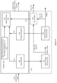
- FIG 2 illustrates a typical processing scheme for a sulfur recovery facility 200, such as used to process feed streams associated with natural gas processing or crude oil refining.
- the sulfur recovery facility 200 has been retrofitted to accept exhaust gas 201 from the reuse catalyst recovery unit 120 and/or the reclaim catalyst recovery unit 130. Details of the retrofit are explained in more detail below.
- the sulfur recovery facility 200 includes a sulfur recovery unit 106, as illustrated in Figure 1 and discussed in more detail below.
- the primary feed stream to the sulfur recovery unit 106 is the acid gas streams from the gas and/or liquid treating systems 202 of the refinery. When the treating system uses an amine solvent, the feed stream 202 may be referred to as an amine acid gas stream.
- Atypical acid gas stream provided to an SRU of a refinery typically comprises hydrogen sulfide, carbon dioxide, water, and possibly small amounts of hydrocarbon gases.
- the acid gas stream may comprise about 40 % to about 95 % H 2 S, about 1 % to about 10 % H 2 O, about 1 % to about 40 % CO 2 , and about 1 % to about 8 % hydrocarbons.
- Some embodiments of a sulfur recovery unit 106 are also configured to process the off-gas from sour water stripping (SWS) systems 204.
- Oxygen (O 2 ) is typically supplied to the SRU 106 in the form of air or O 2 -enriched air.
- the SRU 106 typically converts and recovers 93-98 % of the sulfur contained in the feed streams as elemental sulfur, producing a molten sulfur product, which may be degassed in sulfur degassing unit 206 to reduce/remove the H 2 S remaining in the sulfur.
- the sulfur recovery facility may include a tail gas cleanup unit 208, which converts small amounts of sulfur compounds not converted in the SRU 106 into H 2 S and recycles it back to the SRU 106.
- the effluent gas from the tail gas cleanup unit 208 is incinerated 210, which converts all the remaining sulfur compounds to SO 2 .
- the sulfur recovery unit (SRU) 106 of a typical refinery uses a process, referred to as the Claus Process, to convert hydrogen sulfide from the amine gas stream 202 and/or the sour water stripping stream 204 to elemental sulfur.
- the process involves a multistage catalytic process whereby hydrogen sulfide is oxidized to elemental sulfur according to the overall reaction:
- Each catalytic stage of the sulfur recovery unit 106 typically includes a gas reheater, a catalyst reactor, and a sulfur condenser.
- the Claus process involves using a thermal reactor, such as a furnace, to oxidize a portion, for example one-third, of the H 2 S in an oxygen-containing atmosphere to form SO 2 , according to the following reaction:
- the combustion gases which comprise primarily H 2 S, SO 2 , H 2 O, and N 2 are sent to a condenser whereby elemental sulfur is condensed and separated from the process gases, and the cooled gases exiting the condenser are then sent to the catalytic converters.
- the remaining uncombusted portion of the H 2 S reacts with SO 2 in the catalytic converters to form elemental sulfur, as follows:
- Claus Process-based sulfur recovery units are well known in the art and need not be described here in detail. But what is important to note is that sulfur dioxide (SO 2 ) is a reactant in the Claus Process chemistry. Under typical Claus operation, the SO 2 is produced via the oxidation of H 2 S in the thermal reactor.
- Embodiments of the disclosed methods introduce SO 2 -containing gas streams that are the exhaust combustion gas streams from the catalyst recovery units 120 and/or 130 into the Claus SRU, as illustrated in Figure 3 , which illustrates a retrofitted SRU 106. It should be noted that if additional SRU capability is warranted for handling the SO 2 generated from catalyst recovery, such additional SRU capability can also be used to offload existing SRU workload, which may increase the overall capacity of the refinery. Refinery rates are sometimes limited by the existing SRU capacity; thus, adding additional SRU capacity may serve the dual purposes of (1) treating SO 2 generated by catalyst recovery, and (2) debottlenecking the plant by providing additional SRU capacity for other refinery sulfur-generating processes.
- the SRU 106 illustrated in Figure 3 comprises a thermal reactor (such as a furnace) and two catalytic converters. Upstream of each catalytic converter is a sulfur condenser and a reheater. A final sulfur condenser is provided downstream of the second catalytic converter. It will be appreciated that the SRU 106 may include more or fewer catalytic sections than reflected in Figure 3 .
- One or more exhaust gas streams 201 from the catalyst recovery units 120 and/or 130 are introduced into the SRU along with the amine gas stream(s) 202 and/or the off-gas stream(s) from the sour water stripping units of the refinery. In the illustrated embodiment, each of the streams 201, 202, and 204 are introduced into the thermal reactor of the SRU. However, other embodiments are contemplated.
- the catalyst recovery exhaust stream 201 may be introduced to the air stream or may be added downstream from the thermal reactor, for example, into one of the reheaters or catalytic converters.
- the operation of the thermal reactor can be adjusted to compensate for that additional SO 2 .
- the thermal reactor of the retrofitted SRU is not responsible for generating all of the SO 2 for the Claus chemistry as some of the SO 2 is provided from the catalyst recovery unit exhaust stream(s) 201.
- the thermal reactor conditions are compensated by adjusting the O 2 (air) flow to the thermal reactor.
- the illustrated SRU 106 includes meters 301, 302, and 304 that measure the flow and/or compositions of streams 201, 202, and 204 respectively. Readings from those meters can be used to adjust the amount O 2 provided to the thermal reactor based on the flow and/or composition of the streams 201, 202, and 204.
- the amount of O 2 provided to the thermal reactor can be decreased if a greater amount of SO 2 is being provided to the thermal reactor, thereby decreasing the amount of SO 2 that is generated by oxidizing H 2 S.
- the SRU 106 may include one or more analyzers 306, for example to analyze the composition of the tail gas and to adjust the amount of O 2 provided to the thermal reactor accordingly.
- the analyzer 306 may determine the relative amounts of H 2 S and SO 2 in the tail gas. If the amount of H 2 S is too high, then more O 2 may be provided to the thermal reactor.
- exhaust gas from one or more reuse catalyst recovery unit(s) 120 and/or one or more reclaim catalyst recovery unit(s) 130 can be provided to an SRU 106 of a refinery to treat the SO 2 present in the exhaust gases.
- the exhaust gases may be treated such that the exhaust gases are rendered compatible with the SRU 106.
- the exhaust gases from the catalyst recovery units 120/130 may include particulates, such as catalyst dust, which need to be removed before the gases are piped to the SRU 106.
- embodiments of the disclosed retrofit HDP catalyst recovery system 110 and associated methods include one or more processes and associated equipment for treating the exhaust gases before piping them to the SRU 106.
- particles can be removed from the exhaust gases using techniques and equipment such as one or more cyclones or electrostatic precipitator technology (ESP), such as wet or dry ESP.
- ESP electrostatic precipitator technology
- the exhaust gases from the catalyst recovery units 120/130 may be at elevated temperatures and therefore may need to be cooled before being provided to the SRU 106.
- the reclaim catalyst recovery unit 130 typically operates at temperatures of 1000 °F to about 2000 °F, for example 1800 °F, as described above. Consequently, the exhaust gas exiting the reclaim catalyst recovery unit 130 may have a temperature of about 1800 °F.
- the effluent gases are compressed before they are provided to the SRU. If the gases are to be compressed, they should be cooled, for example, to a temperature below about 400 °F.
- embodiments of the disclosed retrofit HDP catalyst recovery system 110 and associated methods include one or more processes and associated equipment for cooling the exhaust gases.
- the exhaust gas may be cooled using a water quench, a heat exchanger, or the like. Such treatment of the exhaust streams of the catalyst recovery units 120/130 will be implementation specific and within the ability of a person of skill in the art.
- FIG. 4 shows a refinery 100 retrofitted with an alternative embodiment of a HDP catalyst recovery system 610.
- the HDP catalyst recovery system 610 is similar to the embodiment 110 discussed above but includes a sulfur dioxide scrubbing system 620 for separating a portion of the non-SO 2 components, such as CO 2 , H 2 O, and/or N 2 from the combustion gases from the exhaust gases from the reuse bed catalyst recovery unit 120 and/or the reclaim catalyst recovery unit 130.
- the sulfur dioxide scrubbing system 620 provides a gas stream to the SRU which is enriched in SO 2 .
- the sulfur dioxide scrubbing system 620 is illustrated as being included as part of the retrofit catalyst recovery system 610, many refineries include one or more sulfur dioxide scrubbing systems. In such cases, the sulfur dioxide scrubbing equipment of the refinery may be used.
- Exemplary sulfur dioxide scrubbing systems provide for contacting the SO 2 -containing feed (i.e., the exhaust gases) with an SO 2 -adsorbing medium, such as an aminecontaining solvent, for example.
- the exhaust gases are contacted with the SO 2 -absorbing medium, for example, in a counter-current absorption column.
- SO 2 is preferentially absorbed in the SO 2 -absorbing medium to yield an SO 2 -enriched absorbing medium and a SO 2 -depeleted gaseous phase, which is enriched in the non-SO 2 components (e.g., CO 2 , H 2 O, and/or N 2 ).
- the SO 2 is then stripped from the SO 2 -enriched absorbing medium to regenerate lean SO 2 -absorbing medium and to yield a gas stream that is enriched in SO 2 , which can be provided to the SRU.
- An example of an SO 2 scrubbing system is described in U.S. Patent No. 7,214,358, issued May 8, 2007 .
- refineries may not use a Claus-based process for sulfur recovery, and instead may treat the acid gas streams using other technology such as a sulfuric acid plant.
- the H 2 S of the acid gas is incinerated to make SO 2 , which can then be catalytically converted to SO 3 and used to produce sulfuric acid.
- Such sulfur-treating processes of the refinery can also be leveraged to treat the SO 2 -containing combustion gases from the reuse catalyst recovery unit 120 and/or the reclaim catalyst recovery unit 130, as described above.
- the combustion gases may be fed to the incinerator and/or to the catalytic converter of a sulfuric acid plant.
- sulfur recovery unit refers to sulfur abatement technologies based on Claus processes, as well as sulfur abatement technologies based on other processes, such as sulfuric acid plants.
- Sulfur abatement process such as, but not limited to, Claus processes, sulfuric acid plants, and the like, are also referred to herein as sulfur treatment processes (STPs).
- the catalyst recovery units 120 and/or 130 can be used for combusting organics on other wastes such as storage tank sludges and sulfur traps (typically containing Ni and Zn-based catalysts).
- units 120 and 130 are referred to herein as "catalyst recovery units," it should be appreciated that their use is not so limited.
- units 120 and 130 may be used to treat any sulfur-bearing waste derived within a hydrocarbon processing plant, a hydrocarbon upgrading process, a natural gas plant, or the like, and to leverage the sulfur-treatment equipment of such processing plants to abate the generated SO 2 .
- the term “catalyst recovery unit” may be substituted with terms such as "sulfur waste treating unit,” “sulfur waste heating unit,” “sulfur waste oxidation unit,” or the like.
- the waste may be treated before providing it to the treatment unit(s) 120 and/or 130.
- tank bottoms or sludge
- Such waste may be treated to separate the oil from the solids so that the oil can be sold or reprocessed, and the solids can be treated using the treatment unit(s) 120 and/or 130.
- the waste may be treated using one or more mechanical methods, such as centrifugation to separate solid and liquid components of the waste.
Landscapes
- Chemical & Material Sciences (AREA)
- Engineering & Computer Science (AREA)
- Analytical Chemistry (AREA)
- General Chemical & Material Sciences (AREA)
- Oil, Petroleum & Natural Gas (AREA)
- Chemical Kinetics & Catalysis (AREA)
- Environmental & Geological Engineering (AREA)
- Health & Medical Sciences (AREA)
- Biomedical Technology (AREA)
- Production Of Liquid Hydrocarbon Mixture For Refining Petroleum (AREA)
- Catalysts (AREA)
- Exhaust Gas Treatment By Means Of Catalyst (AREA)
- Gas Separation By Absorption (AREA)
- Treating Waste Gases (AREA)
- Treatment Of Sludge (AREA)
Abstract
Description
- The present application relates to techniques for recovering and treating spent catalysts and other sulfur-bearing traps, guards, and wastes from a hydrocarbon refining process.
- Catalytic hydroprocessing (HDP) is applied extensively in the petroleum refining and oil sands upgrading industries to remove impurities, such as heteroatoms (sulfur, nitrogen, oxygen), hydrogenate or hydrocrack heavy hydrocarbons, such as PNAs (polynuclear aromatics), and to remove metal/metalloid contaminants such as (Si, As, Fe, Na, V and Ni). One of the more commonly used catalysts for hydroprocessing comprises one or more Group VIII (Groups 8-10, IUPAC) metals, such as cobalt (Co) or nickel (Ni) and one or more Group VIB (Group 6, IUPAC) metals, such as molybdenum (Mo) or tungsten (W) supported on a carrier material, such as alumina (Al2O3), silica alumina, zeolite, or combinations thereof. When a hydrotreating catalyst is used in a hydrotreating process, the activity of the catalyst decreases over time, due to the accumulation of carboncontaining deposits, referred to as coke, on the catalyst and/or by the presence of deactivating inorganic materials, such as vanadium (V). Some of these catalysts may be regenerated or rejuvenated for reuse, but more often the spent catalysts are not recovered and, instead, are treated as waste. The spent catalysts are often classified as hazardous waste and must be handled accordingly, whether they are sent to a landfill or for regeneration or metals reclamation. Thus, there is a need for more efficient processes for catalyst recovery and catalyst metal reclamation.
- The regeneration or metal reclamation process is typically remote from the refinery or upgrader. The first step in regeneration or reclamation is generally roasting the spent catalyst in the presence of oxygen at elevated temperature. This results in the conversion of the sulfur compounds on the catalyst to volatile sulfur oxide compounds that are considered health and environmental hazards. Common methods of abatement of these sulfur oxide compounds include caustic scrubbing and lime scrubbing. These methods, while effective in preventing the sulfur oxides from entering the atmosphere, create secondary liquid and/or solid waste streams such as sodium sulfate/spent caustic solution or contaminated calcium sulfate solids.
- Disclosed herein are methods of treating a sulfur-bearing waste. According to some embodiments, the method comprises: heating the sulfur-bearing waste to produce a first gas stream, wherein the first gas stream comprises sulfur dioxide (SO2), providing at least a portion of the first gas stream to a sulfur treatment process (STP), providing a second gas stream to the STP, wherein the second gas stream comprises hydrogen sulfide (H2S), providing a third gas stream to the STP, wherein the third gas stream comprises oxygen (O2), and adjusting an amount of the third gas stream provided to the STP to maintain a reaction between SO2 and H2S. According to some embodiments, the STP is an STP of a hydrocarbon processing plant. According to some embodiments, the hydrocarbon processing plant is a hydrocarbon refining plant, a hydrocarbon upgrader, or a natural gas treatment plant. According to some embodiments, the second gas stream comprises one or more gas streams derived from a hydrocarbon processing operation of the hydrocarbon processing plant. According to some embodiments, the second gas stream is selected from the group consisting of an acid gas stream, an amine gas stream, and a sour water stripping off-gas stream. According to some embodiments, the STP comprises a thermal reactor and providing the first, second, and third gas streams to the STP comprises providing the first, second, and third gas streams to the thermal reactor. According to some embodiments, the hydrocarbon processing plant is a hydrocarbon refining plant. According to some embodiments, the sulfur-bearing waste comprises spent hydroprocessing (HDP) catalyst. According to some embodiments, the spent HDP catalyst is derived from the hydrocarbon refining plant. According to some embodiments, the method comprises heating the spent HDP catalyst comprises heating the spent HDP catalyst at a temperature of about 500 °F to about 850 °F. According to some embodiments, heating the spent HDP catalyst comprises first heating the spent HDP catalyst at a first temperature of about 500 °F to about 700 °F to strip the contaminants from the catalyst and then heating the spent HDP catalyst at a second temperature of about 750 °F to about 850 °F in an oxygen-containing atmosphere to remove coke on the spent HDP catalyst and to convert metal sulfides of the spent HDP catalyst to their oxides. According to some embodiments, heating the spent HDP catalyst comprises heating the spent HDP catalyst at a temperature of about 800 °F to about 2000 °F. According to some embodiments, the second gas stream comprises one or more streams selected from the groups consisting of an acid gas stream of a hydrocarbon refining process, an amine gas stream of a hydrocarbon refining process, and a sour water stripping off-gas stream of a hydrocarbon refining process. According to some embodiments, the sulfur-bearing waste comprises tank sludge. According to some embodiments, the sulfur-bearing waste comprises sulfur trap catalyst. According to some embodiments, the method further comprises separating the sulfur-bearing waste from a mixture of oil and the sulfur-bearing waste before heating the sulfur-bearing waste. According to some embodiments, the first gas stream further comprises one or more components selected from the group consisting of carbon dioxide (CO2), water (H2O), and nitrogen (N2) and wherein providing a portion of the first gas stream to the STP comprises treating the first gas stream to provide an SO2-enriched gas stream and providing the SO2-enriched gas stream to the STP. According to some embodiments, treating the first gas stream to provide an SO2-enriched gas stream comprises: contacting the first gas stream with a lean SO2-adsorbing medium to yield an SO2-enriched SO2-adsorbing medium and an SO2-depleted gas, and stripping gaseous SO2-from the SO2-enriched SO2-adsorbing medium to yield the SO2-enriched gas stream. According to some embodiments, the lean SO2-adsorbing medium comprises a solvent comprising an amine. According to some embodiments, adjusting the amount of the third gas stream provided to the STP comprises: determining a feed rate of the at least a portion of the first gas stream to the STP, determining a feed rate of the second gas stream to the STP, and adjusting an amount of the third gas stream provided to the STP based on the determined feed rates. According to some embodiments, adjusting an amount of the third gas stream provided to the STP based on the determined feed rates comprises decreasing the amount of the third gas stream to the STP if the feed rate of the at least a portion of the first gas stream to the STP increases relative to the feed rate of the second gas stream to the STP. According to some embodiments, adjusting the amount of the third gas stream provided to the STP comprises: determining a composition of a tail gas of the STP, and adjusting the amount of the third gas stream provided to the STP based on the determined composition. According to some embodiments, determining the composition of a tail gas of the STP comprises determining a ratio of H2S to SO2 in the tail gas. According to some embodiments, adjusting the amount of the third gas stream provided to the STP based on the determined composition comprises increasing the amount of the third gas stream provided to the STP if the ratio of H2S to SO2 increases. According to some embodiments, providing at least a portion of the first gas stream to the STP comprises treating the first gas stream to remove particulates from the first gas stream. According to some embodiments, the STP comprises a Claus process. According to some embodiments, the STP comprises a sulfuric acid plant.
- Also disclosed herein is a retrofitted refinery comprising, at least one catalyst recovery unit and at least one sulfur treating process (STP), wherein: the at least one catalyst recovery unit is configured to heat a sulfur-bearing waste to produce a first gas stream, wherein the first gas stream comprises sulfur dioxide (SO2); and wherein the SRU unit is configured to: receive the first gas stream, receive a second gas stream, wherein the second gas stream comprises hydrogen sulfide (H2S), and receive a third gas stream, wherein the third gas stream comprises oxygen (O2), wherein the amount of the third gas stream provided to the SRU is adjusted to maintain a reaction between SO2 and H2S in the STP. According to some embodiments, the sulfur-bearing waste comprises spent HDP catalyst. According to some embodiments, the STP comprises a Claus process. According to some embodiments, the STP comprises a thermal reactor and wherein the first, second, and third gas streams are received at the thermal reactor. According to some embodiments, the at least one catalyst recovery unit comprises a reactor configured to heat the spent HDP catalyst at a temperature of about 500 °F to about 850 °F. According to some embodiments, the at least one catalyst recovery unit comprises a reactor configured to heat the spent HDP catalyst at a first temperature of about 500 °F to about 700 °F to strip the contaminants from the catalyst and then to heat the spent HDP catalyst at a second temperature of about 750 °F to about 850 °F in an oxygen-containing atmosphere to remove coke on the spent HDP catalyst and to convert metal sulfides of the spent HDP catalyst to their oxides. According to some embodiments, the at least one catalyst recovery unit comprises a reactor configured to heat the spent HDP catalyst at a temperature of about 800 °F to about 2000 °F. According to some embodiments, the second gas stream comprises one or more streams selected from the groups consisting of an acid gas stream of the retrofitted refinery, an amine gas stream of retrofitted refinery, and a sour water stripping off-gas stream of retrofitted refinery. According to some embodiments, the first gas stream further comprises one or more components selected from the group consisting of carbon dioxide (CO2), water (H2O), and nitrogen (N2) and wherein the retrofitted refinery further comprises an SO2 scrubber configured to treat the first gas stream to provide an SO2-enriched gas stream to the STP. According to some embodiments, treating the first gas stream to provide an SO2-enriched gas stream comprises: contacting the first gas stream with a lean SO2-adsorbing medium to yield an SO2-enriched SO2-adsorbing medium and an SO2-depleted gas, and stripping gaseous SO2-from the SO2-enriched SO2-adsorbing medium to yield the SO2-enriched gas stream. According to some embodiments, the lean SO2-adsorbing medium comprises a solvent comprising an amine. According to some embodiments, adjusting the amount of the third gas stream provided to the STP comprises: determining a feed rate of the at least a portion of the first gas stream to the STP, determining a feed rate of the second gas stream to the STP, and adjusting an amount of the third gas stream provided to the STP based on the determined feed rates. According to some embodiments, adjusting an amount of the third gas stream provided to the STP based on the determined feed rates comprises decreasing the amount of the third gas stream to the STP if the feed rate of the at least a portion of the first gas stream to the STP increases relative to the feed rate of the second gas stream to the STP. According to some embodiments, adjusting the amount of the third gas stream provided to the STP comprises: determining a composition of a tail gas of the STP, and adjusting the amount of the third gas stream provided to the STP based on the determined composition. According to some embodiments, determining the composition of a tail gas of the STP comprises determining a ratio of H2S to SO2 in the tail gas. According to some embodiments, adjusting the amount of the third gas stream provided to the STP based on the determined composition comprises increasing the amount of the third gas stream provided to the STP if the ratio of H2S to SO2 increases. According to some embodiments, the retrofitted refinery further comprises one or more pieces of equipment configured to treat the first gas stream to remove particulates from the first gas stream before the STP receives the first gas stream. According to some embodiments, the one or more pieces of equipment is selected from the group consisting of one or more cyclones and one or more electrostatic precipitators. According to some embodiments, the refinery further comprises one or more pieces of equipment configured to treat the first gas stream to lower the temperature of the first gas stream before the STP receives the first gas stream. According to some embodiments, the one or more pieces of equipment is selected from the group consisting of one or more water quenchers and one or more heat exchanger. Also disclosed herein are methods of retrofitting a refinery, natural gas processing plant, hydrocarbon upgrading plant/process, or the like, by providing/assembling the equipment describe above.
- Also disclosed herein is a method of treating a sulfur-bearing waste, the method comprising: heating the sulfur-bearing waste to produce a first gas stream, wherein the first gas stream comprises sulfur dioxide (SO2), providing at least a portion of the first gas stream to a sulfur treating process (STP), and providing a second gas stream to the STP, wherein the second gas stream comprises hydrogen sulfide (H2S). According to some embodiments, the STP comprises a Claus process. According to some embodiments, the method further comprises: providing a third gas stream to the STP, wherein the third gas stream comprises oxygen (O2), and adjusting an amount of the third gas stream provided to the STP to maintain a reaction between SO2 and H2S. According to some embodiments, the STP comprises a sulfuric acid plant. According to some embodiments, the sulfur-bearing waste comprises spent HDP catalyst. According to some embodiments, the sulfur-bearing waste comprises storage tank sludge or sulfur trap catalyst.
-
-
Figure 1 shows a refinery retrofitted with a HDP catalyst recovery system. -
Figure 2 shows a sulfur recovery facility. -
Figure 3 shows a schematic of a Claus sulfur recovery unit. -
Figure 4 shows refinery retrofitted with an alternative embodiment of a HDP catalyst recovery system. - As mentioned above, HDP catalysts become spent during use and must be removed from the HDP units of the refinery. Handling of the spent catalyst poses several problems. The spent catalyst typically contains catalytic and contaminant metals in the sulfide form as well as liquid hydrocarbons and hydrocarbon deposits (i.e., coke). Such contaminants increase the weight of the catalyst material and, in many cases, may render the spent catalyst hazardous and/or self-heating, which increases the costs of handling and transporting the spent catalyst.
- Thermal stripping/oxidation technologies exist that can render the spent catalyst non-self-heating and/or convert it to a hazardous product rather than a waste. However, such oxidation processes convert the sulfur and sulfur-containing compounds present on the spent catalyst into sulfur dioxide (SO2), which must be captured or treated using a sulfur abatement technology. Such sulfur abatement equipment and processing add a significant cost to treating the spent catalyst.
- The methods and systems described in this disclosure leverage the sulfur abatement resources that are present at treating facilities such as refineries and gas processing plants to capture and treat sulfur-containing byproducts, such as SO2, that are generated during the regeneration of sulfur-bearing wastes, such as spent HDP catalysts. These sulfur abatement resources at the treating facility, e.g., the Claus sulfur recovery process, recover elemental sulfur as a product that can be used in fertilizer or other valuable products. To date, the removal of sulfur compounds from spent catalyst (by roasting or regeneration in an oxygen containing gas) has not been successfully integrated into the treating facility's Claus sulfur recovery system. The subject disclosure describes how this may be successfully done, thus converting the hazardous waste spent catalyst to a salable product at its source while simultaneously capturing the sulfur oxides removed from the catalyst and converting them to a useful product instead of a resultant waste stream requiring management and/or disposal. Thus, spent HDP catalyst can be roasted or regenerated at the refinery site or other treating facility that incorporates sulfur abatement.
-
Figure 1 illustrates a high-level schematic of ahydrocarbon refinery 100, retrofitted with an HDPcatalyst recovery system 110, as described herein. It will be appreciated that a hydrocarbon refinery includes many processes and pieces of equipment that are not illustrated inFigure 1 and that are familiar to a person of skill in the art. But for the purposes of this discussion, two HDP units are illustrated.HDP unit 102 can be a fixed bed hydrotreating unit, such as typically used to treat atmospheric distillation products and light products from the vacuum distillation within therefinery 100.HDP unit 104 can be fixed bed or an ebullated bed unit, such as typically used to treat residue from the vacuum distillation within the refinery.HDP unit 104 may be referred to herein as a resid-treating unit (RTU). - Again, it should be emphasized that
HDP units Figure 1 is intended to illustrate two contexts in which HDP units are employed. Generally, catalysts in both types ofHDP units HDP unit 104 catalyst picks up large amounts of metals, such as vanadium as the heavy residual oil is upgraded to lighter weight oil or synthetic crude oil. - Generally, spent catalyst derived from the treatment of atmospheric distillation products and light products (such as in HDP unit 102) may be regenerated/reclaimed for reuse. Contrarily, spent catalyst derived from the treatment of residual oil and other heavy feeds (such as in HDP unit 104) may be too contaminated with metal-containing materials to be reused as catalyst even after such catalysts are treated to remove the accumulate deposits of hydrocarbon, other carbonaceous materials, sulfur-containing materials. Thus, the value in treating such spent catalyst is primarily to reclaim/recycle the component metals. However, it should be noted that these generalities may not always apply. For example, top beds of light feed treatments (i.e., HDP unit 102) may produce spent catalyst that is too poisoned for regeneration/reuse. Likewise, spent catalyst from the treatment of some resids and other heavy products (i.e., HDP unit 104) may still be suitable for regeneration and reuse. The point is that the catalyst treatment/regeneration methods and systems described herein may be used either for catalyst regeneration/reuse and/or for metals reclamation.
- Referring again to
Figure 1 , the retrofit HDPcatalyst recovery system 110 includes two HDPcatalyst recovery units 120 and 130. It should be noted that while two HDP catalyst recovery units are illustrated for the purposes of this discussion, the retrofit HDP catalyst recovery system may include more or fewer than two HDP catalyst recovery units. - The HDP catalyst recovery unit 120 is referred to herein as a reuse catalyst recovery unit, because generally, the purpose of the reuse catalyst recovery unit 120 is to treat (i.e., regenerate) a spent HDP catalyst for reuse. The HDP
catalyst recovery unit 130 is referred to herein as a reclaim catalyst recovery unit, because generally, the purpose of the reclaimcatalyst recovery unit 130 is to render the spent HDP catalyst safe (e.g., non-self-heating) for further reclamation of the catalyst components, such as metals within the catalyst. The illustration is intended to show that the reuse catalyst recovery unit 120 may typically be used to treat catalyst derived from hydrotreating processes that operate on lighter materials whereas the reclaimcatalyst recovery unit 130 may typically be used to treat catalyst derived from hydrotreating processes that operate on heavier materials, such as residuum. As mentioned above, embodiments of the disclosed system may include one of or both types of HDP treatment units. - As mentioned above, the purpose of the reuse catalyst recovery unit 120 is to recover and treat spent HDP catalyst that has low levels of contaminants generated by refinery processes such as naphtha hydrotreaters, kerosene or jet hydrotreaters, distillate hydrotreaters, and other reactors, or certain beds in reactors, that have low levels of contaminants when the catalyst is removed from the reactors. According to some embodiments, the reuse catalyst recovery unit 120 can comprise a first stage for stripping free hydrocarbons from the spent catalyst, if any significant levels are present, and a second stage for regeneration of the spent catalyst in an oxygen-containing gas to remove coke on the catalyst and convert the catalyst metal sulfides to their oxide form. The first stage, i.e., stripping free hydrocarbons from the spent catalyst, may comprise thermal desorption of the hydrocarbons from the spent catalyst. Alternatively, or in addition, hydrocarbons may be removed by washing the spent catalyst with an organic solvent or with an aqueous medium that comprises surfactants and/or detergents. Equipment used for the reuse catalyst recovery unit 120 may include a moving belt regenerator, a fluidized bed, a rotolouver, a rotary calciner, or other equipment known in the art. For clarity, auxiliary equipment associated with the reuse catalyst recovery unit 120 has been omitted from
Figure 1 . However, such auxiliary equipment will be apparent to a person of skill in the art. For example, the reuse catalyst recovery unit 120 has associated equipment for providing fuel (e.g., natural gas) for operating the unit as well as equipment for providing air to the unit. - According to some embodiments, spent catalyst from the (one or more) HDP unit(s) 102 are transported to the reuse catalyst recovery unit 120. Typically, the spent catalyst may comprise one or more Group VIII (Groups 8-10, IUPAC) metals, such as cobalt (Co) or nickel (Ni) and one or more Group VIB (Group 6, IUPAC) metals, such as molybdenum (Mo) or tungsten (W) supported on a carrier material, such as alumina (Al2O3), silica alumina, zeolite, or combinations thereof. The spent catalyst may be contaminated with hydrocarbon and carbonaceous contaminants from the HDP process. The spent catalyst may be heated in the reuse catalyst recovery unit 120 to strip those contaminants from the catalyst and to regenerate the spent catalyst. For example, the spent catalyst may be heated within a temperature range of about 500 °F to about 900 °F. According to some embodiments, the reuse catalyst recovery unit 120 may employ multiple heating stages. For example, in a first stage the spent catalyst may be heated within a temperature range of about 500 °F to about 700 °F to strip the contaminants from the catalyst. Alternatively (or additionally) the spent catalyst may be washed with organic solvent and/or with an aqueous medium that may contain one or more surfactants and/or detergents. Then a second stage may be employed whereby the stripped catalyst is heated in an oxygen-containing atmosphere at a temperature of about 750 °F to about 900 °F to remove coke on the catalyst and convert the catalyst metal sulfides to their oxide form (i.e., to regenerate the catalyst). The oxygen-containing gas may be air or oxygen-enriched air, for example.
- Heating the spent catalyst during the stripping and/or regeneration stages yields an exhaust gas that typically comprises SO2, CO2, H2O, and N2. For example, the exhaust gas may comprise about 65 % to about 85 % N2, about 10 % to about 20 % O2, about 0.1 % to about 0.4 % CO2, and about 0.05 % to about 0.2 % SO2. As explained in more detail below, the exhaust from the reuse catalyst recovery unit 120 can be provided to the refinery's sulfur recovery unit (SRU) 106.
- Referring again to
Figure 1 , recall that the purpose of the reclaimcatalyst recovery unit 130 is to recover and treat spent HDP catalyst derived from hydrotreating processes that operate on heavier materials, such as hydrocarbon residues, and to render the spent HDP catalyst safe (i.e., non-self-heating) for transport, for example. Generally, the spent catalyst treated in the reclaimcatalyst recovery unit 130 are richer in metal contaminants, such as vanadium. There are several thermal oxidation units that can be used for the reclaimcatalyst recovery unit 130, including direct-fired kilns, rotolouvers, multiple hearth furnaces, moving belt regenerators, etc. A direct-fired rotary kiln is particularly well suited to roast the catalyst at temperatures in the range of 800 °F to 2000 °F. This roasting process removes most of the sulfur and carbon from the catalyst and eliminates any self-heating hazards associated with the catalyst. Roasting the spent catalyst during in the reclaimcatalyst recovery unit 130 yields an exhaust gas that typically comprises SO2, CO2, H2O, and N2. For example, the exhaust gas may comprise about 65% to about 85 % N2, about 5 % to about 30 % O2, about 1 % to about 20 % CO2, and about 0.1 % to about 4 % SO2. As explained in more detail below, the exhaust from the reclaimcatalyst recovery unit 130 can be provided to the refinery's sulfur recovery unit (SRU) 106. For clarity, auxiliary equipment associated with the reclaimcatalyst recovery unit 130 has been omitted fromFigure 1 . However, such auxiliary equipment will be apparent to a person of skill in the art. For example, the reclaimcatalyst recovery unit 130 has associated equipment for providing fuel (e.g., natural gas) for operating the unit as well as equipment for providing air to the unit. According to some embodiments, the reclaimcatalyst recovery unit 130 may be self-sustaining once roasting is initiated. - Referring again to
Figure 1 , the illustratedrefinery 100 also includes sulfur recovery unit (SRU) 106. The main purpose of sulfur recovery facilities of the refinery is pollution control. Crude oils, oil sands and natural gas streams contain sulfur compounds throughout the boiling range from low molecular weight mercaptans to very high molecular weight residuum. The hydroprocessing (HDP) of these compounds, such as inUnits 102 and/or 104 ofFigure 1 , forms hydrogen sulfide (H2S) gas as a byproduct. Sulfur recovery is a critical part of most refineries because, in most jurisdictions, it is required by law to minimize emissions of sulfur compounds to the environment. Sulfur recovery facilities convert H2S gas to produce marketable products (e.g., sulfuric acid and/or elemental sulfur). -
Figure 2 illustrates a typical processing scheme for asulfur recovery facility 200, such as used to process feed streams associated with natural gas processing or crude oil refining. Thesulfur recovery facility 200 has been retrofitted to acceptexhaust gas 201 from the reuse catalyst recovery unit 120 and/or the reclaimcatalyst recovery unit 130. Details of the retrofit are explained in more detail below. Thesulfur recovery facility 200 includes asulfur recovery unit 106, as illustrated inFigure 1 and discussed in more detail below. The primary feed stream to thesulfur recovery unit 106 is the acid gas streams from the gas and/or liquid treating systems 202 of the refinery. When the treating system uses an amine solvent, the feed stream 202 may be referred to as an amine acid gas stream. Atypical acid gas stream provided to an SRU of a refinery typically comprises hydrogen sulfide, carbon dioxide, water, and possibly small amounts of hydrocarbon gases. For example, the acid gas stream may comprise about 40 % to about 95 % H2S, about 1 % to about 10 % H2O, about 1 % to about 40 % CO2, and about 1 % to about 8 % hydrocarbons. Some embodiments of asulfur recovery unit 106 are also configured to process the off-gas from sour water stripping (SWS)systems 204. Oxygen (O2) is typically supplied to theSRU 106 in the form of air or O2-enriched air. TheSRU 106 typically converts and recovers 93-98 % of the sulfur contained in the feed streams as elemental sulfur, producing a molten sulfur product, which may be degassed insulfur degassing unit 206 to reduce/remove the H2S remaining in the sulfur. The sulfur recovery facility may include a tailgas cleanup unit 208, which converts small amounts of sulfur compounds not converted in theSRU 106 into H2S and recycles it back to theSRU 106. The effluent gas from the tailgas cleanup unit 208 is incinerated 210, which converts all the remaining sulfur compounds to SO2. - The sulfur recovery unit (SRU) 106 of a typical refinery uses a process, referred to as the Claus Process, to convert hydrogen sulfide from the amine gas stream 202 and/or the sour
water stripping stream 204 to elemental sulfur. The process involves a multistage catalytic process whereby hydrogen sulfide is oxidized to elemental sulfur according to the overall reaction:
- Note that the stoichiometry of the above reaction is exemplary only and may change due to modifications in the particulars of the Claus reactions. Each catalytic stage of the
sulfur recovery unit 106 typically includes a gas reheater, a catalyst reactor, and a sulfur condenser. - The Claus process involves using a thermal reactor, such as a furnace, to oxidize a portion, for example one-third, of the H2S in an oxygen-containing atmosphere to form SO2, according to the following reaction:

- The combustion gases, which comprise primarily H2S, SO2, H2O, and N2 are sent to a condenser whereby elemental sulfur is condensed and separated from the process gases, and the cooled gases exiting the condenser are then sent to the catalytic converters. In each stage, the remaining uncombusted portion of the H2S reacts with SO2 in the catalytic converters to form elemental sulfur, as follows:

- Claus Process-based sulfur recovery units are well known in the art and need not be described here in detail. But what is important to note is that sulfur dioxide (SO2) is a reactant in the Claus Process chemistry. Under typical Claus operation, the SO2 is produced via the oxidation of H2S in the thermal reactor. Embodiments of the disclosed methods introduce SO2-containing gas streams that are the exhaust combustion gas streams from the catalyst recovery units 120 and/or 130 into the Claus SRU, as illustrated in
Figure 3 , which illustrates a retrofittedSRU 106. It should be noted that if additional SRU capability is warranted for handling the SO2 generated from catalyst recovery, such additional SRU capability can also be used to offload existing SRU workload, which may increase the overall capacity of the refinery. Refinery rates are sometimes limited by the existing SRU capacity; thus, adding additional SRU capacity may serve the dual purposes of (1) treating SO2 generated by catalyst recovery, and (2) debottlenecking the plant by providing additional SRU capacity for other refinery sulfur-generating processes. - The
SRU 106 illustrated inFigure 3 comprises a thermal reactor (such as a furnace) and two catalytic converters. Upstream of each catalytic converter is a sulfur condenser and a reheater. A final sulfur condenser is provided downstream of the second catalytic converter. It will be appreciated that theSRU 106 may include more or fewer catalytic sections than reflected inFigure 3 . One or more exhaust gas streams 201 from the catalyst recovery units 120 and/or 130 are introduced into the SRU along with the amine gas stream(s) 202 and/or the off-gas stream(s) from the sour water stripping units of the refinery. In the illustrated embodiment, each of thestreams recovery exhaust stream 201 may be introduced to the air stream or may be added downstream from the thermal reactor, for example, into one of the reheaters or catalytic converters. - As some amount of SO2 is introduced into the
SRU 106 via stream(s) 201, the operation of the thermal reactor can be adjusted to compensate for that additional SO2. In other words, the thermal reactor of the retrofitted SRU is not responsible for generating all of the SO2 for the Claus chemistry as some of the SO2 is provided from the catalyst recovery unit exhaust stream(s) 201. The thermal reactor conditions are compensated by adjusting the O2 (air) flow to the thermal reactor. The illustratedSRU 106 includesmeters streams streams SRU 106 may include one or more analyzers 306, for example to analyze the composition of the tail gas and to adjust the amount of O2 provided to the thermal reactor accordingly. For example, the analyzer 306 may determine the relative amounts of H2S and SO2 in the tail gas. If the amount of H2S is too high, then more O2 may be provided to the thermal reactor. - The above discussion and
Figures 1 - 3 describe how exhaust gas from one or more reuse catalyst recovery unit(s) 120 and/or one or more reclaim catalyst recovery unit(s) 130 can be provided to anSRU 106 of a refinery to treat the SO2 present in the exhaust gases. According to some embodiments, the exhaust gases may be treated such that the exhaust gases are rendered compatible with theSRU 106. For example, the exhaust gases from the catalyst recovery units 120/130 may include particulates, such as catalyst dust, which need to be removed before the gases are piped to theSRU 106. Thus, embodiments of the disclosed retrofit HDPcatalyst recovery system 110 and associated methods include one or more processes and associated equipment for treating the exhaust gases before piping them to theSRU 106. For example, particles can be removed from the exhaust gases using techniques and equipment such as one or more cyclones or electrostatic precipitator technology (ESP), such as wet or dry ESP. - Likewise, according to some embodiments, the exhaust gases from the catalyst recovery units 120/130 may be at elevated temperatures and therefore may need to be cooled before being provided to the
SRU 106. For example, the reclaimcatalyst recovery unit 130 typically operates at temperatures of 1000 °F to about 2000 °F, for example 1800 °F, as described above. Consequently, the exhaust gas exiting the reclaimcatalyst recovery unit 130 may have a temperature of about 1800 °F. According to some embodiments, the effluent gases are compressed before they are provided to the SRU. If the gases are to be compressed, they should be cooled, for example, to a temperature below about 400 °F. Thus, embodiments of the disclosed retrofit HDPcatalyst recovery system 110 and associated methods include one or more processes and associated equipment for cooling the exhaust gases. According to some embodiments, the exhaust gas may be cooled using a water quench, a heat exchanger, or the like. Such treatment of the exhaust streams of the catalyst recovery units 120/130 will be implementation specific and within the ability of a person of skill in the art. -
Figure 4 shows arefinery 100 retrofitted with an alternative embodiment of a HDPcatalyst recovery system 610. The HDPcatalyst recovery system 610 is similar to theembodiment 110 discussed above but includes a sulfurdioxide scrubbing system 620 for separating a portion of the non-SO2 components, such as CO2, H2O, and/or N2 from the combustion gases from the exhaust gases from the reuse bed catalyst recovery unit 120 and/or the reclaimcatalyst recovery unit 130. Thus, the sulfurdioxide scrubbing system 620 provides a gas stream to the SRU which is enriched in SO2. It should be noted, that while the sulfurdioxide scrubbing system 620 is illustrated as being included as part of the retrofitcatalyst recovery system 610, many refineries include one or more sulfur dioxide scrubbing systems. In such cases, the sulfur dioxide scrubbing equipment of the refinery may be used. - Examples of sulfur dioxide scrubbing systems are well known in the art and need not be described here in detail. Exemplary sulfur dioxide scrubbing systems provide for contacting the SO2-containing feed (i.e., the exhaust gases) with an SO2-adsorbing medium, such as an aminecontaining solvent, for example. According to some embodiments, the exhaust gases are contacted with the SO2-absorbing medium, for example, in a counter-current absorption column. SO2 is preferentially absorbed in the SO2-absorbing medium to yield an SO2-enriched absorbing medium and a SO2-depeleted gaseous phase, which is enriched in the non-SO2 components (e.g., CO2, H2O, and/or N2). The SO2 is then stripped from the SO2-enriched absorbing medium to regenerate lean SO2-absorbing medium and to yield a gas stream that is enriched in SO2, which can be provided to the SRU. An example of an SO2 scrubbing system is described in
U.S. Patent No. 7,214,358, issued May 8, 2007 . - It should be noted that some refineries may not use a Claus-based process for sulfur recovery, and instead may treat the acid gas streams using other technology such as a sulfuric acid plant. According to some such processes, the H2S of the acid gas is incinerated to make SO2, which can then be catalytically converted to SO3 and used to produce sulfuric acid. Such sulfur-treating processes of the refinery can also be leveraged to treat the SO2-containing combustion gases from the reuse catalyst recovery unit 120 and/or the reclaim
catalyst recovery unit 130, as described above. For example, the combustion gases may be fed to the incinerator and/or to the catalytic converter of a sulfuric acid plant. As used in this disclosure, the term "sulfur recovery unit (SRU)" refers to sulfur abatement technologies based on Claus processes, as well as sulfur abatement technologies based on other processes, such as sulfuric acid plants. Sulfur abatement process, such as, but not limited to, Claus processes, sulfuric acid plants, and the like, are also referred to herein as sulfur treatment processes (STPs). - A person of skill in the art will appreciate that methods and systems of treating sulfur-bearing wastes have been disclosed herein. The disclosure focuses primarily on treating sulfur-bearing spent catalysts used in hydrotreating process. However, the methods and systems described herein can be applied to other sulfur-bearing wastes in a refinery setting. For example, the catalyst recovery units 120 and/or 130 can be used for combusting organics on other wastes such as storage tank sludges and sulfur traps (typically containing Ni and Zn-based catalysts). Thus, while
units 120 and 130 are referred to herein as "catalyst recovery units," it should be appreciated that their use is not so limited. In other words,units 120 and 130 may be used to treat any sulfur-bearing waste derived within a hydrocarbon processing plant, a hydrocarbon upgrading process, a natural gas plant, or the like, and to leverage the sulfur-treatment equipment of such processing plants to abate the generated SO2. Thus, throughout this specification, the term "catalyst recovery unit" may be substituted with terms such as "sulfur waste treating unit," "sulfur waste heating unit," "sulfur waste oxidation unit," or the like. Depending on the nature and composition of the sulfur-bearing waste, the waste may be treated before providing it to the treatment unit(s) 120 and/or 130. For example, tank bottoms (or sludge) may comprise solids and oil. Such waste may be treated to separate the oil from the solids so that the oil can be sold or reprocessed, and the solids can be treated using the treatment unit(s) 120 and/or 130. For example, the waste may be treated using one or more mechanical methods, such as centrifugation to separate solid and liquid components of the waste. - The above discussion primarily focuses on embodiments wherein catalyst recovery systems are implemented in a refinery setting and particularly wherein such systems leverage the refinery's sulfur-treatment equipment to abate the SO2 produced during catalyst recovery. However other embodiments can be implemented in settings other than refineries that include sulfur-treatment. For example, natural gas processing plants typically include Claus and/or other sulfur abatement facilities and such facilities can be leveraged to treat SO2 produced during catalyst recovery, as described above. For example, spent catalyst from processes such as oil sands/bitumen upgrading may be regenerated at a natural gas processing plant and the plant's sulfur-treatment facilities used to treat the produced SO2.
- Certain embodiments and features have been described using a set of numerical upper limits and a set of numerical lower limits. It should be appreciated that ranges from any lower limit to any upper limit are contemplated unless otherwise indicated. Certain lower limits, upper limits and ranges may appear in one or more claims below. All numerical values are "about" or "approximately" the indicated value, and take into account numerical error and variations that would be expected by a person having ordinary skill in the art. Unless otherwise noted, "about" may be interpreted to imply plus or minus 10 percent. The use of the word "a" or "an" when used in conjunction with the term "comprising" in the claims or the specification means one or more than one, unless the context dictates otherwise. The use of the term "or" in the claims is used to mean "and/or" unless explicitly indicated to refer to alternatives only or if the alternatives are mutually exclusive. The terms "comprise", "have", "include" and "contain" (and their variants) are open-ended linking verbs and allow the addition of other elements when used in a claim.
- While the invention herein disclosed has been described in terms of specific embodiments and applications thereof, numerous modifications and variations could be made thereto by those skilled in the art without departing from the scope of the invention set forth in the claims.
Claims (12)
- A method of treating a sulfur-bearing waste, the method comprising:heating the sulfur-bearing waste to produce a first gas stream, wherein the first gas stream comprises sulfur dioxide (SO2),providing at least a portion of the first gas stream to a sulfur treatment process (STP),providing a second gas stream to the STP, wherein the second gas stream comprises hydrogen sulfide (H2S),providing a third gas stream to the STP, wherein the third gas stream comprises oxygen (O2), andadjusting an amount of the third gas stream provided to the STP to maintain a reaction between SO2 and H2S,wherein the STP is an STP of a hydrocarbon processing plant,wherein the hydrocarbon processing plant is a hydrocarbon refining plant and wherein the sulfur-bearing waste comprises spent hydroprocessing (HDP) catalyst derived from the hydrocarbon refining plant,wherein adjusting the amount of the third gas stream provided to the STP comprises:determining a composition of a tail gas of the STP, andadjusting the amount of the third gas stream provided to the STP based on the determined composition,wherein determining the composition of a tail gas of the STP comprises determining a ratio of H2S to SO2 in the tail gas,wherein providing at least a portion of the first gas stream to the STP comprises treating the first gas stream to remove particulates from the first gas stream,wherein the STP comprises a Claus process.
- The method of claim 1, wherein the second gas stream comprises one or more gas streams derived from a hydrocarbon processing operation of the hydrocarbon processing plant.
- The method of claim 2, wherein the second gas stream is selected from the group consisting of an acid gas stream, an amine gas stream, and a sour water stripping off-gas stream.
- The method of claim 2, wherein the sulfur-bearing waste comprises tank sludge.
- The method of claim 2, wherein the sulfur-bearing waste comprises sulfur trap catalyst.
- The method of claim 2, further comprising separating the sulfur-bearing waste from a mixture of oil and the sulfur-bearing waste before heating the sulfur-bearing waste.
- The method of claim 1, wherein the first gas stream further comprises one or more components selected from the group consisting of carbon dioxide (CO2), water (H2O), and nitrogen (N2) and wherein providing a portion of the first gas stream to the STP comprises treating the first gas stream to provide an SO2-enriched gas stream and providing the SO2-enriched gas stream to the STP.
- The method of claim 7, wherein treating the first gas stream to provide an SO2-enriched gas stream comprises:contacting the first gas stream with a lean SO2-adsorbing medium to yield an SO2-enriched SO2-adsorbing medium and an SO2-depleted gas, andstripping gaseous SO2-from the SO2-enriched SO2-adsorbing medium to yield the SO2-enriched gas stream.
- The method of claim 8, wherein the lean SO2-adsorbing medium comprises a solvent comprising an amine.
- The method of claim 1, wherein adjusting the amount of the third gas stream provided to the STP comprises:determining a feed rate of the at least a portion of the first gas stream to the STP,determining a feed rate of the second gas stream to the STP, andadjusting an amount of the third gas stream provided to the STP based on the determined feed rates.
- The method of claim 10, wherein adjusting an amount of the third gas stream provided to the STP based on the determined feed rates comprises decreasing the amount of the third gas stream to the STP if the feed rate of the at least a portion of the first gas stream to the STP increases relative to the feed rate of the second gas stream to the STP.
- The method of claim 1, wherein adjusting the amount of the third gas stream provided to the STP based on the determined composition comprises increasing the amount of the third gas stream provided to the STP if the ratio of H2S to SO2 increases.
Applications Claiming Priority (3)
| Application Number | Priority Date | Filing Date | Title |
|---|---|---|---|
| US201862742524P | 2018-10-08 | 2018-10-08 | |
| EP19801432.6A EP3863752A1 (en) | 2018-10-08 | 2019-10-07 | Method of processing sulfur-bearing wastes from refineries and upgraders |
| PCT/US2019/055026 WO2020076717A1 (en) | 2018-10-08 | 2019-10-07 | Method of processing sulfur-bearing wastes from refineries and upgraders |
Related Parent Applications (1)
| Application Number | Title | Priority Date | Filing Date |
|---|---|---|---|
| EP19801432.6A Division EP3863752A1 (en) | 2018-10-08 | 2019-10-07 | Method of processing sulfur-bearing wastes from refineries and upgraders |
Publications (1)
| Publication Number | Publication Date |
|---|---|
| EP4140565A1 true EP4140565A1 (en) | 2023-03-01 |
Family
ID=68503197
Family Applications (2)
| Application Number | Title | Priority Date | Filing Date |
|---|---|---|---|
| EP19801432.6A Withdrawn EP3863752A1 (en) | 2018-10-08 | 2019-10-07 | Method of processing sulfur-bearing wastes from refineries and upgraders |
| EP22202998.5A Withdrawn EP4140565A1 (en) | 2018-10-08 | 2019-10-07 | Method of processing sulfur-bearing wastes from refineries and upgraders |
Family Applications Before (1)
| Application Number | Title | Priority Date | Filing Date |
|---|---|---|---|
| EP19801432.6A Withdrawn EP3863752A1 (en) | 2018-10-08 | 2019-10-07 | Method of processing sulfur-bearing wastes from refineries and upgraders |
Country Status (11)
| Country | Link |
|---|---|
| US (2) | US10850229B2 (en) |
| EP (2) | EP3863752A1 (en) |
| JP (1) | JP7491937B2 (en) |
| KR (1) | KR102812441B1 (en) |
| CN (1) | CN112912162A (en) |
| BR (1) | BR112021006628A2 (en) |
| CA (1) | CA3115392A1 (en) |
| MX (1) | MX2021004014A (en) |
| SA (1) | SA521421667B1 (en) |
| WO (1) | WO2020076717A1 (en) |
| ZA (1) | ZA202103025B (en) |
Families Citing this family (2)
| Publication number | Priority date | Publication date | Assignee | Title |
|---|---|---|---|---|
| KR102812441B1 (en) * | 2018-10-08 | 2025-05-23 | 에보닉 오퍼레이션스 게엠베하 | Method for treating sulfur-containing waste from refineries and upgraders |
| MY205563A (en) * | 2019-05-23 | 2024-10-26 | Evonik Operations Gmbh | Reactivated hydroprocessing catalysts for use in sulfur abatement |
Citations (4)
| Publication number | Priority date | Publication date | Assignee | Title |
|---|---|---|---|---|
| US4233276A (en) * | 1979-03-30 | 1980-11-11 | Standard Oil Company (Indiana) | Process for the desulfurization of waste gases |
| EP1230149B1 (en) * | 1999-10-22 | 2005-12-14 | MECS, Inc. | Process for the production of sulfur |
| US7214358B2 (en) | 2003-08-13 | 2007-05-08 | Cansolv Technologies Inc. | Low energy regenerable SO2 scrubbing process |
| WO2016102652A1 (en) * | 2014-12-24 | 2016-06-30 | Prosernat | Removal of hydrogen sulfide and sulfur recovery from a gas stream by catalytic direct oxidation and claus reaction |
Family Cites Families (24)
| Publication number | Priority date | Publication date | Assignee | Title |
|---|---|---|---|---|
| US2919976A (en) * | 1956-06-08 | 1960-01-05 | Pan American Petroleum Corp | Conversion of hydrogen sulfide into free sulfur |
| US3681024A (en) * | 1970-08-10 | 1972-08-01 | Amoco Prod Co | Method for production of sulfur from hydrogen sulfide using oxygen |
| US3781445A (en) * | 1971-12-10 | 1973-12-25 | Exxon Research Engineering Co | Recovery of sulphur |
| JPS5495969A (en) * | 1978-01-11 | 1979-07-28 | Kobe Steel Ltd | Desulfurizing method for gas containing hydrogen sulfide |
| JPS54107801A (en) * | 1978-02-14 | 1979-08-24 | Chiyoda Chem Eng & Constr Co Ltd | Separating and recovering mehtod for metal from waste catalyst |
| JPS60118610A (en) * | 1983-11-29 | 1985-06-26 | Mitsui Miike Kakoki Kk | Removal of harmful component in device for reducing so2 |
| GB8407843D0 (en) * | 1984-03-27 | 1984-05-02 | Shell Int Research | Removal of sulphur compounds from off-gases |
| DE3415722A1 (en) * | 1984-04-27 | 1985-10-31 | Metallgesellschaft Ag, 6000 Frankfurt | METHOD FOR REMOVING SULFUR HYDROGEN FROM EXHAUST GAS AND FOR GENERATING IN SULFUR AFTER THE CLAUS PROCESS |
| EP0252497A3 (en) * | 1986-07-09 | 1988-05-25 | Air Products And Chemicals, Inc. | Sulfor dioxide injection for claus furnace temperature moderation |
| US4769229A (en) * | 1986-09-25 | 1988-09-06 | Amoco Corporation | Sulfur recovery process using metal oxide absorber feed for regeneration |
| US4871521A (en) * | 1987-09-18 | 1989-10-03 | Amoco Corporation | Sulfur recovery process using metal oxide absorbent with improved purge |
| DE4121290A1 (en) * | 1991-06-27 | 1993-01-07 | Linde Ag | PROCESS FOR THE THERMAL IMPLEMENTATION OF SULFUR HYDROGEN TO ELEMENTARY SULFUR |
| US5965100A (en) * | 1995-04-25 | 1999-10-12 | Khanmamedov; Tofik K. | Process for recovery of sulfur from an acid gas stream |
| EP1142628A3 (en) * | 2000-04-05 | 2001-11-28 | The BOC Group plc | Treatment of gas streams containing hydrogen sulphide |
| CN100475313C (en) * | 2007-02-13 | 2009-04-08 | 西安中宇软件科技有限责任公司 | Sulfur dioxide recovery split method Sulfur recovery device and system device Sulfur recovery method |
| US8808654B2 (en) * | 2009-09-29 | 2014-08-19 | Praxair Technology, Inc. | Process for sulfur removal from refinery off gas |
| WO2011090553A1 (en) * | 2010-01-22 | 2011-07-28 | Exxonmobil Upstream Research Company | Removal of acid gases from a gas stream, with co2 capture and sequestration |
| US8562928B2 (en) * | 2011-09-21 | 2013-10-22 | Shell Oil Company | Process for producing hydrogen, sulfur and sulfur dioxide from hydrogen sulfide-containing gas streams |
| FR3000097B1 (en) * | 2012-12-20 | 2014-12-26 | Ifp Energies Now | INTEGRATED PROCESS FOR THE TREATMENT OF PETROLEUM LOADS FOR THE PRODUCTION OF LOW SULFUR CONTENT FIELDS |
| DK2784022T3 (en) * | 2013-03-28 | 2015-08-24 | Linde Ag | The oxygen use in the Claus plant which is loaded with an additional load ¿in particular a combustion gas containing SO 2 and come from adsorptionsmiddelregenerering |
| CA2981133A1 (en) * | 2015-03-27 | 2016-10-06 | Porocel International, Llc | Presulfurized catalyst composition |
| US20180065851A1 (en) * | 2016-09-03 | 2018-03-08 | Mahin Rameshni | Setr- super enhanced tail gas recovery; a tail gas process with adsorbent reactors for zero emissions |
| JP2020062571A (en) | 2017-02-09 | 2020-04-23 | 独立行政法人石油天然ガス・金属鉱物資源機構 | Hydrogen sulfide removal system and hydrogen sulfide removal method |
| KR102812441B1 (en) * | 2018-10-08 | 2025-05-23 | 에보닉 오퍼레이션스 게엠베하 | Method for treating sulfur-containing waste from refineries and upgraders |
-
2019
- 2019-10-07 KR KR1020217013751A patent/KR102812441B1/en active Active
- 2019-10-07 BR BR112021006628A patent/BR112021006628A2/en not_active Application Discontinuation
- 2019-10-07 JP JP2021544105A patent/JP7491937B2/en active Active
- 2019-10-07 WO PCT/US2019/055026 patent/WO2020076717A1/en not_active Ceased
- 2019-10-07 CN CN201980066228.1A patent/CN112912162A/en active Pending
- 2019-10-07 EP EP19801432.6A patent/EP3863752A1/en not_active Withdrawn
- 2019-10-07 CA CA3115392A patent/CA3115392A1/en active Pending
- 2019-10-07 MX MX2021004014A patent/MX2021004014A/en unknown
- 2019-10-07 US US16/595,051 patent/US10850229B2/en active Active
- 2019-10-07 EP EP22202998.5A patent/EP4140565A1/en not_active Withdrawn
-
2020
- 2020-11-25 US US17/104,880 patent/US11351500B2/en active Active
-
2021
- 2021-04-06 SA SA521421667A patent/SA521421667B1/en unknown
- 2021-05-05 ZA ZA2021/03025A patent/ZA202103025B/en unknown
Patent Citations (4)
| Publication number | Priority date | Publication date | Assignee | Title |
|---|---|---|---|---|
| US4233276A (en) * | 1979-03-30 | 1980-11-11 | Standard Oil Company (Indiana) | Process for the desulfurization of waste gases |
| EP1230149B1 (en) * | 1999-10-22 | 2005-12-14 | MECS, Inc. | Process for the production of sulfur |
| US7214358B2 (en) | 2003-08-13 | 2007-05-08 | Cansolv Technologies Inc. | Low energy regenerable SO2 scrubbing process |
| WO2016102652A1 (en) * | 2014-12-24 | 2016-06-30 | Prosernat | Removal of hydrogen sulfide and sulfur recovery from a gas stream by catalytic direct oxidation and claus reaction |
Non-Patent Citations (5)
| Title |
|---|
| BURWELL CRYSTAPHASE JOHN: "High-efficiency filtration extends SRU cycle length", DIGITAL REFINING, 30 November 2017 (2017-11-30), pages 1 - 2, XP093001648, Retrieved from the Internet <URL:ww.digitalrefining.com/article/1001444/high-efficiency-filtration-extends-sru-cycle-length-ert.pdf> [retrieved on 20221124] * |
| LAGAS J A ET AL: "THE SUPERCLAUS PROCESS", 9 March 1988 (1988-03-09), 38th Annual Laurance Reid Gas Conditioning Conference; Norman, Oklahomoa (USA), pages 1 - 19, XP093001636, Retrieved from the Internet <URL:https://pacs.ou.edu/media/filer_public/87/4c/874cb105-463b-4fa0-9729-e5cad8942314/11_the_superclaus_process_for_sulfur_recovery_by_lagas_borsboom_and_berban.pdf> [retrieved on 20221124] * |
| LIYA ZHANG: "The Common Malfunction and Treatment Method of SuperClaus Process Equipment", 2013 INTERNATIONAL CONFERENCE ON COMPUTATIONAL AND INFORMATION SCIENCES, IEEE, 21 June 2013 (2013-06-21), pages 1300 - 1302, XP032514821, DOI: 10.1109/ICCIS.2013.344 * |
| RYUICHIRO IWAMOTO: "REGENERATION OF RESIDUE HYDRODESULFURIZATION CATALYST", JOURNAL OF THE JAPAN PETROLEUM INSTITUTE , 56 (3), 31 December 2013 (2013-12-31), pages 109 - 121, XP055652607, Retrieved from the Internet <URL:https://www.jstage.jst.go.jp/article/jpi/56/3/56_109/_pdf> [retrieved on 20191213] * |
| SANNAZZARO R.: "ABSORPTION AND RECOVERY OF SULPHUR FROM FLUE GAS OF THE FLUID CATALYTIC CRACKING (FCC) BY A SPECIAL REUSABLE BUFFER.", 1 January 2006 (2006-01-01), pages 1 - 6, XP093001744, Retrieved from the Internet <URL:https://webgate.ec.europa.eu/life/publicWebsite/project/details/1729> [retrieved on 20221124] * |
Also Published As
| Publication number | Publication date |
|---|---|
| ZA202103025B (en) | 2022-04-28 |
| US20200108345A1 (en) | 2020-04-09 |
| CN112912162A (en) | 2021-06-04 |
| BR112021006628A2 (en) | 2021-07-06 |
| KR102812441B1 (en) | 2025-05-23 |
| US20210077950A1 (en) | 2021-03-18 |
| US10850229B2 (en) | 2020-12-01 |
| JP2022508650A (en) | 2022-01-19 |
| EP3863752A1 (en) | 2021-08-18 |
| US11351500B2 (en) | 2022-06-07 |
| JP7491937B2 (en) | 2024-05-28 |
| CA3115392A1 (en) | 2020-04-16 |
| KR20210066915A (en) | 2021-06-07 |
| WO2020076717A1 (en) | 2020-04-16 |
| MX2021004014A (en) | 2021-07-16 |
| SA521421667B1 (en) | 2022-10-23 |
Similar Documents
| Publication | Publication Date | Title |
|---|---|---|
| US20220040629A1 (en) | Pitch destruction processes using thermal oxidation system | |
| CA2764641C (en) | Process for recovering metals from a stream rich in hydrocarbons and carbonaceous residues | |
| US20140079614A1 (en) | Process for Reducing Sulfur Emission of Sulfur Plant | |
| JP2013522454A (en) | Metal recovery from refining residues | |
| CN102369236A (en) | Environmentally clean process for utilizing pyrolysis products | |
| US20090285738A1 (en) | Direct oxidation of sulfur with carbon dioxide recycle | |
| NO174933B (en) | Process for Hydrogenation Conversion of Heavy Oils and Residual Oils | |
| US11351500B2 (en) | Method of processing sulfur-bearing wastes from refineries and upgraders | |
| EP1966346A1 (en) | Hybrid energy system | |
| EP2784022B1 (en) | Oxygen application in Claus units charged with an additional load -particularly a waste-gas stream containing SO2 and coming from adsorbent regeneration | |
| CN113046127A (en) | Demetallization of hydrocarbons | |
| EP3463627A1 (en) | A method for the removal of oxygen from an industrial gas | |
| CA1182807A (en) | Regeneration of zncl.sub.2 | |
| US10933372B2 (en) | Method for the removal of oxygen from an industrial gas feed | |
| US7052661B1 (en) | Method for abatement of mercury emissions from combustion gases | |
| RU2827330C2 (en) | Method of treating sulphur-containing wastes from processing and concentration industries | |
| HK40047186A (en) | Method of processing sulfur-bearing wastes from refineries and upgraders | |
| JPS5869288A (en) | Method for refining hydrocarbon distillate fraction | |
| CN110748895A (en) | High-sulfur waste incineration treatment system and treatment method | |
| Pereira | Recovery and Recycling of Spent Ni–Mo–V Catalysts: Technologies, Environmental Drivers and Circular Economy Perspectives | |
| EP0063537A2 (en) | Method for the disposal of sulfur oxides from a catalytic cracking operation | |
| RU2210536C1 (en) | Coke gas desulfurization process | |
| WO2017129655A1 (en) | System for the exploitation of bitumen and related process | |
| Hossain | Catalytic, Inc., Philadelphia, Pennsylvania | |
| Hossain et al. | and Alfred B. Cherry Catalytic, Inc., Philadelphia, Pennsylvania |
Legal Events
| Date | Code | Title | Description |
|---|---|---|---|
| PUAI | Public reference made under article 153(3) epc to a published international application that has entered the european phase |
Free format text: ORIGINAL CODE: 0009012 |
|
| STAA | Information on the status of an ep patent application or granted ep patent |
Free format text: STATUS: REQUEST FOR EXAMINATION WAS MADE |
|
| 17P | Request for examination filed |
Effective date: 20221021 |
|
| AC | Divisional application: reference to earlier application |
Ref document number: 3863752 Country of ref document: EP Kind code of ref document: P |
|
| AK | Designated contracting states |
Kind code of ref document: A1 Designated state(s): AL AT BE BG CH CY CZ DE DK EE ES FI FR GB GR HR HU IE IS IT LI LT LU LV MC MK MT NL NO PL PT RO RS SE SI SK SM TR |
|
| STAA | Information on the status of an ep patent application or granted ep patent |
Free format text: STATUS: THE APPLICATION IS DEEMED TO BE WITHDRAWN |
|
| 18D | Application deemed to be withdrawn |
Effective date: 20230902 |