EP4140452A1 - Vertebral cage - Google Patents
Vertebral cage Download PDFInfo
- Publication number
- EP4140452A1 EP4140452A1 EP21837600.2A EP21837600A EP4140452A1 EP 4140452 A1 EP4140452 A1 EP 4140452A1 EP 21837600 A EP21837600 A EP 21837600A EP 4140452 A1 EP4140452 A1 EP 4140452A1
- Authority
- EP
- European Patent Office
- Prior art keywords
- side end
- vertebra
- base
- elastic
- band
- Prior art date
- Legal status (The legal status is an assumption and is not a legal conclusion. Google has not performed a legal analysis and makes no representation as to the accuracy of the status listed.)
- Granted
Links
Images


Classifications
-
- A—HUMAN NECESSITIES
- A61—MEDICAL OR VETERINARY SCIENCE; HYGIENE
- A61F—FILTERS IMPLANTABLE INTO BLOOD VESSELS; PROSTHESES; DEVICES PROVIDING PATENCY TO, OR PREVENTING COLLAPSING OF, TUBULAR STRUCTURES OF THE BODY, e.g. STENTS; ORTHOPAEDIC, NURSING OR CONTRACEPTIVE DEVICES; FOMENTATION; TREATMENT OR PROTECTION OF EYES OR EARS; BANDAGES, DRESSINGS OR ABSORBENT PADS; FIRST-AID KITS
- A61F2/00—Filters implantable into blood vessels; Prostheses, i.e. artificial substitutes or replacements for parts of the body; Appliances for connecting them with the body; Devices providing patency to, or preventing collapsing of, tubular structures of the body, e.g. stents
- A61F2/02—Prostheses implantable into the body
- A61F2/30—Joints
- A61F2/44—Joints for the spine, e.g. vertebrae, spinal discs
- A61F2/4455—Joints for the spine, e.g. vertebrae, spinal discs for the fusion of spinal bodies, e.g. intervertebral fusion of adjacent spinal bodies, e.g. fusion cages
-
- A—HUMAN NECESSITIES
- A61—MEDICAL OR VETERINARY SCIENCE; HYGIENE
- A61F—FILTERS IMPLANTABLE INTO BLOOD VESSELS; PROSTHESES; DEVICES PROVIDING PATENCY TO, OR PREVENTING COLLAPSING OF, TUBULAR STRUCTURES OF THE BODY, e.g. STENTS; ORTHOPAEDIC, NURSING OR CONTRACEPTIVE DEVICES; FOMENTATION; TREATMENT OR PROTECTION OF EYES OR EARS; BANDAGES, DRESSINGS OR ABSORBENT PADS; FIRST-AID KITS
- A61F2/00—Filters implantable into blood vessels; Prostheses, i.e. artificial substitutes or replacements for parts of the body; Appliances for connecting them with the body; Devices providing patency to, or preventing collapsing of, tubular structures of the body, e.g. stents
- A61F2/02—Prostheses implantable into the body
- A61F2/30—Joints
- A61F2/44—Joints for the spine, e.g. vertebrae, spinal discs
- A61F2/442—Intervertebral or spinal discs, e.g. resilient
-
- A—HUMAN NECESSITIES
- A61—MEDICAL OR VETERINARY SCIENCE; HYGIENE
- A61F—FILTERS IMPLANTABLE INTO BLOOD VESSELS; PROSTHESES; DEVICES PROVIDING PATENCY TO, OR PREVENTING COLLAPSING OF, TUBULAR STRUCTURES OF THE BODY, e.g. STENTS; ORTHOPAEDIC, NURSING OR CONTRACEPTIVE DEVICES; FOMENTATION; TREATMENT OR PROTECTION OF EYES OR EARS; BANDAGES, DRESSINGS OR ABSORBENT PADS; FIRST-AID KITS
- A61F2/00—Filters implantable into blood vessels; Prostheses, i.e. artificial substitutes or replacements for parts of the body; Appliances for connecting them with the body; Devices providing patency to, or preventing collapsing of, tubular structures of the body, e.g. stents
- A61F2/02—Prostheses implantable into the body
- A61F2/30—Joints
- A61F2002/30001—Additional features of subject-matter classified in A61F2/28, A61F2/30 and subgroups thereof
- A61F2002/30003—Material related properties of the prosthesis or of a coating on the prosthesis
- A61F2002/30004—Material related properties of the prosthesis or of a coating on the prosthesis the prosthesis being made from materials having different values of a given property at different locations within the same prosthesis
- A61F2002/30014—Material related properties of the prosthesis or of a coating on the prosthesis the prosthesis being made from materials having different values of a given property at different locations within the same prosthesis differing in elasticity, stiffness or compressibility
-
- A—HUMAN NECESSITIES
- A61—MEDICAL OR VETERINARY SCIENCE; HYGIENE
- A61F—FILTERS IMPLANTABLE INTO BLOOD VESSELS; PROSTHESES; DEVICES PROVIDING PATENCY TO, OR PREVENTING COLLAPSING OF, TUBULAR STRUCTURES OF THE BODY, e.g. STENTS; ORTHOPAEDIC, NURSING OR CONTRACEPTIVE DEVICES; FOMENTATION; TREATMENT OR PROTECTION OF EYES OR EARS; BANDAGES, DRESSINGS OR ABSORBENT PADS; FIRST-AID KITS
- A61F2/00—Filters implantable into blood vessels; Prostheses, i.e. artificial substitutes or replacements for parts of the body; Appliances for connecting them with the body; Devices providing patency to, or preventing collapsing of, tubular structures of the body, e.g. stents
- A61F2/02—Prostheses implantable into the body
- A61F2/30—Joints
- A61F2002/30001—Additional features of subject-matter classified in A61F2/28, A61F2/30 and subgroups thereof
- A61F2002/30003—Material related properties of the prosthesis or of a coating on the prosthesis
- A61F2002/3006—Properties of materials and coating materials
- A61F2002/30069—Properties of materials and coating materials elastomeric
-
- A—HUMAN NECESSITIES
- A61—MEDICAL OR VETERINARY SCIENCE; HYGIENE
- A61F—FILTERS IMPLANTABLE INTO BLOOD VESSELS; PROSTHESES; DEVICES PROVIDING PATENCY TO, OR PREVENTING COLLAPSING OF, TUBULAR STRUCTURES OF THE BODY, e.g. STENTS; ORTHOPAEDIC, NURSING OR CONTRACEPTIVE DEVICES; FOMENTATION; TREATMENT OR PROTECTION OF EYES OR EARS; BANDAGES, DRESSINGS OR ABSORBENT PADS; FIRST-AID KITS
- A61F2/00—Filters implantable into blood vessels; Prostheses, i.e. artificial substitutes or replacements for parts of the body; Appliances for connecting them with the body; Devices providing patency to, or preventing collapsing of, tubular structures of the body, e.g. stents
- A61F2/02—Prostheses implantable into the body
- A61F2/30—Joints
- A61F2002/30001—Additional features of subject-matter classified in A61F2/28, A61F2/30 and subgroups thereof
- A61F2002/30108—Shapes
- A61F2002/30199—Three-dimensional shapes
- A61F2002/30224—Three-dimensional shapes cylindrical
- A61F2002/30225—Flat cylinders, i.e. discs
- A61F2002/30227—Flat cylinders, i.e. discs arched, domed or vaulted
-
- A—HUMAN NECESSITIES
- A61—MEDICAL OR VETERINARY SCIENCE; HYGIENE
- A61F—FILTERS IMPLANTABLE INTO BLOOD VESSELS; PROSTHESES; DEVICES PROVIDING PATENCY TO, OR PREVENTING COLLAPSING OF, TUBULAR STRUCTURES OF THE BODY, e.g. STENTS; ORTHOPAEDIC, NURSING OR CONTRACEPTIVE DEVICES; FOMENTATION; TREATMENT OR PROTECTION OF EYES OR EARS; BANDAGES, DRESSINGS OR ABSORBENT PADS; FIRST-AID KITS
- A61F2/00—Filters implantable into blood vessels; Prostheses, i.e. artificial substitutes or replacements for parts of the body; Appliances for connecting them with the body; Devices providing patency to, or preventing collapsing of, tubular structures of the body, e.g. stents
- A61F2/02—Prostheses implantable into the body
- A61F2/30—Joints
- A61F2002/30001—Additional features of subject-matter classified in A61F2/28, A61F2/30 and subgroups thereof
- A61F2002/30108—Shapes
- A61F2002/30199—Three-dimensional shapes
- A61F2002/30286—Three-dimensional shapes barrel-shaped
-
- A—HUMAN NECESSITIES
- A61—MEDICAL OR VETERINARY SCIENCE; HYGIENE
- A61F—FILTERS IMPLANTABLE INTO BLOOD VESSELS; PROSTHESES; DEVICES PROVIDING PATENCY TO, OR PREVENTING COLLAPSING OF, TUBULAR STRUCTURES OF THE BODY, e.g. STENTS; ORTHOPAEDIC, NURSING OR CONTRACEPTIVE DEVICES; FOMENTATION; TREATMENT OR PROTECTION OF EYES OR EARS; BANDAGES, DRESSINGS OR ABSORBENT PADS; FIRST-AID KITS
- A61F2/00—Filters implantable into blood vessels; Prostheses, i.e. artificial substitutes or replacements for parts of the body; Appliances for connecting them with the body; Devices providing patency to, or preventing collapsing of, tubular structures of the body, e.g. stents
- A61F2/02—Prostheses implantable into the body
- A61F2/30—Joints
- A61F2002/30001—Additional features of subject-matter classified in A61F2/28, A61F2/30 and subgroups thereof
- A61F2002/30316—The prosthesis having different structural features at different locations within the same prosthesis; Connections between prosthetic parts; Special structural features of bone or joint prostheses not otherwise provided for
- A61F2002/30535—Special structural features of bone or joint prostheses not otherwise provided for
- A61F2002/30537—Special structural features of bone or joint prostheses not otherwise provided for adjustable
-
- A—HUMAN NECESSITIES
- A61—MEDICAL OR VETERINARY SCIENCE; HYGIENE
- A61F—FILTERS IMPLANTABLE INTO BLOOD VESSELS; PROSTHESES; DEVICES PROVIDING PATENCY TO, OR PREVENTING COLLAPSING OF, TUBULAR STRUCTURES OF THE BODY, e.g. STENTS; ORTHOPAEDIC, NURSING OR CONTRACEPTIVE DEVICES; FOMENTATION; TREATMENT OR PROTECTION OF EYES OR EARS; BANDAGES, DRESSINGS OR ABSORBENT PADS; FIRST-AID KITS
- A61F2/00—Filters implantable into blood vessels; Prostheses, i.e. artificial substitutes or replacements for parts of the body; Appliances for connecting them with the body; Devices providing patency to, or preventing collapsing of, tubular structures of the body, e.g. stents
- A61F2/02—Prostheses implantable into the body
- A61F2/30—Joints
- A61F2002/30001—Additional features of subject-matter classified in A61F2/28, A61F2/30 and subgroups thereof
- A61F2002/30316—The prosthesis having different structural features at different locations within the same prosthesis; Connections between prosthetic parts; Special structural features of bone or joint prostheses not otherwise provided for
- A61F2002/30535—Special structural features of bone or joint prostheses not otherwise provided for
- A61F2002/30537—Special structural features of bone or joint prostheses not otherwise provided for adjustable
- A61F2002/30546—Special structural features of bone or joint prostheses not otherwise provided for adjustable for adjusting elasticity, flexibility, spring rate or mechanical tension
-
- A—HUMAN NECESSITIES
- A61—MEDICAL OR VETERINARY SCIENCE; HYGIENE
- A61F—FILTERS IMPLANTABLE INTO BLOOD VESSELS; PROSTHESES; DEVICES PROVIDING PATENCY TO, OR PREVENTING COLLAPSING OF, TUBULAR STRUCTURES OF THE BODY, e.g. STENTS; ORTHOPAEDIC, NURSING OR CONTRACEPTIVE DEVICES; FOMENTATION; TREATMENT OR PROTECTION OF EYES OR EARS; BANDAGES, DRESSINGS OR ABSORBENT PADS; FIRST-AID KITS
- A61F2/00—Filters implantable into blood vessels; Prostheses, i.e. artificial substitutes or replacements for parts of the body; Appliances for connecting them with the body; Devices providing patency to, or preventing collapsing of, tubular structures of the body, e.g. stents
- A61F2/02—Prostheses implantable into the body
- A61F2/30—Joints
- A61F2002/30001—Additional features of subject-matter classified in A61F2/28, A61F2/30 and subgroups thereof
- A61F2002/30316—The prosthesis having different structural features at different locations within the same prosthesis; Connections between prosthetic parts; Special structural features of bone or joint prostheses not otherwise provided for
- A61F2002/30535—Special structural features of bone or joint prostheses not otherwise provided for
- A61F2002/30563—Special structural features of bone or joint prostheses not otherwise provided for having elastic means or damping means, different from springs, e.g. including an elastomeric core or shock absorbers
-
- A—HUMAN NECESSITIES
- A61—MEDICAL OR VETERINARY SCIENCE; HYGIENE
- A61F—FILTERS IMPLANTABLE INTO BLOOD VESSELS; PROSTHESES; DEVICES PROVIDING PATENCY TO, OR PREVENTING COLLAPSING OF, TUBULAR STRUCTURES OF THE BODY, e.g. STENTS; ORTHOPAEDIC, NURSING OR CONTRACEPTIVE DEVICES; FOMENTATION; TREATMENT OR PROTECTION OF EYES OR EARS; BANDAGES, DRESSINGS OR ABSORBENT PADS; FIRST-AID KITS
- A61F2/00—Filters implantable into blood vessels; Prostheses, i.e. artificial substitutes or replacements for parts of the body; Appliances for connecting them with the body; Devices providing patency to, or preventing collapsing of, tubular structures of the body, e.g. stents
- A61F2/02—Prostheses implantable into the body
- A61F2/30—Joints
- A61F2002/30001—Additional features of subject-matter classified in A61F2/28, A61F2/30 and subgroups thereof
- A61F2002/30316—The prosthesis having different structural features at different locations within the same prosthesis; Connections between prosthetic parts; Special structural features of bone or joint prostheses not otherwise provided for
- A61F2002/30535—Special structural features of bone or joint prostheses not otherwise provided for
- A61F2002/30565—Special structural features of bone or joint prostheses not otherwise provided for having spring elements
-
- A—HUMAN NECESSITIES
- A61—MEDICAL OR VETERINARY SCIENCE; HYGIENE
- A61F—FILTERS IMPLANTABLE INTO BLOOD VESSELS; PROSTHESES; DEVICES PROVIDING PATENCY TO, OR PREVENTING COLLAPSING OF, TUBULAR STRUCTURES OF THE BODY, e.g. STENTS; ORTHOPAEDIC, NURSING OR CONTRACEPTIVE DEVICES; FOMENTATION; TREATMENT OR PROTECTION OF EYES OR EARS; BANDAGES, DRESSINGS OR ABSORBENT PADS; FIRST-AID KITS
- A61F2/00—Filters implantable into blood vessels; Prostheses, i.e. artificial substitutes or replacements for parts of the body; Appliances for connecting them with the body; Devices providing patency to, or preventing collapsing of, tubular structures of the body, e.g. stents
- A61F2/02—Prostheses implantable into the body
- A61F2/30—Joints
- A61F2/30767—Special external or bone-contacting surface, e.g. coating for improving bone ingrowth
- A61F2/30907—Nets or sleeves applied to surface of prostheses or in cement
- A61F2002/30909—Nets
- A61F2002/30914—Details of the mesh structure, e.g. disposition of the woven warp and weft wires
-
- A—HUMAN NECESSITIES
- A61—MEDICAL OR VETERINARY SCIENCE; HYGIENE
- A61F—FILTERS IMPLANTABLE INTO BLOOD VESSELS; PROSTHESES; DEVICES PROVIDING PATENCY TO, OR PREVENTING COLLAPSING OF, TUBULAR STRUCTURES OF THE BODY, e.g. STENTS; ORTHOPAEDIC, NURSING OR CONTRACEPTIVE DEVICES; FOMENTATION; TREATMENT OR PROTECTION OF EYES OR EARS; BANDAGES, DRESSINGS OR ABSORBENT PADS; FIRST-AID KITS
- A61F2/00—Filters implantable into blood vessels; Prostheses, i.e. artificial substitutes or replacements for parts of the body; Appliances for connecting them with the body; Devices providing patency to, or preventing collapsing of, tubular structures of the body, e.g. stents
- A61F2/02—Prostheses implantable into the body
- A61F2/30—Joints
- A61F2/30767—Special external or bone-contacting surface, e.g. coating for improving bone ingrowth
- A61F2002/3092—Special external or bone-contacting surface, e.g. coating for improving bone ingrowth having an open-celled or open-pored structure
-
- A—HUMAN NECESSITIES
- A61—MEDICAL OR VETERINARY SCIENCE; HYGIENE
- A61F—FILTERS IMPLANTABLE INTO BLOOD VESSELS; PROSTHESES; DEVICES PROVIDING PATENCY TO, OR PREVENTING COLLAPSING OF, TUBULAR STRUCTURES OF THE BODY, e.g. STENTS; ORTHOPAEDIC, NURSING OR CONTRACEPTIVE DEVICES; FOMENTATION; TREATMENT OR PROTECTION OF EYES OR EARS; BANDAGES, DRESSINGS OR ABSORBENT PADS; FIRST-AID KITS
- A61F2/00—Filters implantable into blood vessels; Prostheses, i.e. artificial substitutes or replacements for parts of the body; Appliances for connecting them with the body; Devices providing patency to, or preventing collapsing of, tubular structures of the body, e.g. stents
- A61F2/02—Prostheses implantable into the body
- A61F2/30—Joints
- A61F2/3094—Designing or manufacturing processes
- A61F2002/30971—Laminates, i.e. layered products
-
- A—HUMAN NECESSITIES
- A61—MEDICAL OR VETERINARY SCIENCE; HYGIENE
- A61F—FILTERS IMPLANTABLE INTO BLOOD VESSELS; PROSTHESES; DEVICES PROVIDING PATENCY TO, OR PREVENTING COLLAPSING OF, TUBULAR STRUCTURES OF THE BODY, e.g. STENTS; ORTHOPAEDIC, NURSING OR CONTRACEPTIVE DEVICES; FOMENTATION; TREATMENT OR PROTECTION OF EYES OR EARS; BANDAGES, DRESSINGS OR ABSORBENT PADS; FIRST-AID KITS
- A61F2/00—Filters implantable into blood vessels; Prostheses, i.e. artificial substitutes or replacements for parts of the body; Appliances for connecting them with the body; Devices providing patency to, or preventing collapsing of, tubular structures of the body, e.g. stents
- A61F2/02—Prostheses implantable into the body
- A61F2/30—Joints
- A61F2/44—Joints for the spine, e.g. vertebrae, spinal discs
- A61F2002/448—Joints for the spine, e.g. vertebrae, spinal discs comprising multiple adjacent spinal implants within the same intervertebral space or within the same vertebra, e.g. comprising two adjacent spinal implants
- A61F2002/4485—Joints for the spine, e.g. vertebrae, spinal discs comprising multiple adjacent spinal implants within the same intervertebral space or within the same vertebra, e.g. comprising two adjacent spinal implants comprising three or more adjacent spinal implants
-
- A—HUMAN NECESSITIES
- A61—MEDICAL OR VETERINARY SCIENCE; HYGIENE
- A61F—FILTERS IMPLANTABLE INTO BLOOD VESSELS; PROSTHESES; DEVICES PROVIDING PATENCY TO, OR PREVENTING COLLAPSING OF, TUBULAR STRUCTURES OF THE BODY, e.g. STENTS; ORTHOPAEDIC, NURSING OR CONTRACEPTIVE DEVICES; FOMENTATION; TREATMENT OR PROTECTION OF EYES OR EARS; BANDAGES, DRESSINGS OR ABSORBENT PADS; FIRST-AID KITS
- A61F2/00—Filters implantable into blood vessels; Prostheses, i.e. artificial substitutes or replacements for parts of the body; Appliances for connecting them with the body; Devices providing patency to, or preventing collapsing of, tubular structures of the body, e.g. stents
- A61F2/02—Prostheses implantable into the body
- A61F2/30—Joints
- A61F2/44—Joints for the spine, e.g. vertebrae, spinal discs
- A61F2002/4495—Joints for the spine, e.g. vertebrae, spinal discs having a fabric structure, e.g. made from wires or fibres
-
- A—HUMAN NECESSITIES
- A61—MEDICAL OR VETERINARY SCIENCE; HYGIENE
- A61F—FILTERS IMPLANTABLE INTO BLOOD VESSELS; PROSTHESES; DEVICES PROVIDING PATENCY TO, OR PREVENTING COLLAPSING OF, TUBULAR STRUCTURES OF THE BODY, e.g. STENTS; ORTHOPAEDIC, NURSING OR CONTRACEPTIVE DEVICES; FOMENTATION; TREATMENT OR PROTECTION OF EYES OR EARS; BANDAGES, DRESSINGS OR ABSORBENT PADS; FIRST-AID KITS
- A61F2310/00—Prostheses classified in A61F2/28 or A61F2/30 - A61F2/44 being constructed from or coated with a particular material
- A61F2310/00005—The prosthesis being constructed from a particular material
- A61F2310/00011—Metals or alloys
- A61F2310/00023—Titanium or titanium-based alloys, e.g. Ti-Ni alloys
Definitions
- the present disclosure relates to a spinal cage inserted between vertebrae to support the vertebrae.
- Intervertebral discs serve as joints, and a nucleus pulposus located in the center of each disc changes its position and shape with movement of the spine, thereby playing an important role of minimizing impact applied to the spine.
- a method of treating a disease involving a disc there is a method of treatment in which a disc between damaged vertebrae is removed, and then a space between two adjacent vertebrae is replaced with a prosthetic material such as a cage.
- the cage helps restore an original distance between two adjacent vertebral bodies, which is an original height of the intervertebral disc, to restore the functions of the spine.
- the cage has a solid structure made of a metal material such as titanium or a titanium alloy, and sometimes, a problem occurs in which, after the cage is inserted between a vertebra and a neighboring vertebra and surgery is completed, surfaces of the vertebra and the neighboring vertebra that face each other subside due to an upper surface and a lower surface of the cage.
- a metal material such as titanium or a titanium alloy
- Patent Document 1 Korean Patent Publication no. 10-2016-0128236 [Disclosure]
- the present disclosure provides a spinal cage which can suppress subsidence of a spinal cage inserted between vertebrae into the vertebrae.
- a spinal cage including: a bone support portion disposed between a first vertebra at an upper side and a second vertebra at a lower side, which neighbor each other, to support the first vertebra; a base portion positioned at a lower side of the bone support portion and disposed between the first vertebra and the second vertebra to come in contact with the second vertebra; and a sidewall portion which has an upper side end connected to an edge of the bone support portion and a lower side end connected to an edge of the base portion to support the bone support portion relative to the base portion and which includes an elastic band having elasticity and inelastic bands having relatively lower elasticity than the elastic band or no elasticity.
- the inelastic bands may include a first inelastic band which has an upper side connected to the edge of the bone support portion and a lower side connected to the elastic band and a second inelastic band which has an upper side connected to the elastic band and a lower side connected to the edge of the base portion, and the elastic band may be positioned between the first inelastic band and the second inelastic band and be elastically deformable corresponding to a pressure between the first vertebra and the second vertebra.
- the elastic band may have a form in which a cross-sectional thickness gradually increases from a center of the elastic band toward an edge thereof.
- first inelastic band and the second inelastic band may be formed so that elasticity gradually decreases from the elastic band toward the bone support portion or the base portion.
- the elastic band may be an assembly formed by consecutive connection of a plurality of elastic unit bodies which are elastically deformable corresponding to an external force.
- the elastic unit body may be deformable according to the external force and may include a plurality of struts connecting vertices and crossing points of a virtual hexahedron, and the crossing points may be points provided at positions spaced apart at predetermined intervals inward of the virtual hexahedron at a face-centered of the virtual hexahedron.
- the strut of the elastic unit body may have an arch shape or a curved shape.
- the elastic unit body may include a base beam which has one side end positioned on a vertex of a virtual hexahedron and is formed to have a predetermined length in a height direction, an impact absorbing beam which has one side end connected to the other side end of the base beam, forms an acute angle relative to the base beam, and is formed to have a predetermined length, and a support beam which has one side end connected to the other side end of the impact absorbing beam and the other side end connected to the other side end of another impact absorbing beam to have a predetermined length and which has a longitudinal direction parallel to the base beam.
- the elastic unit body may include a base beam which has one side end positioned on a vertex of a virtual hexahedron and is formed to have a predetermined length in a height direction, an impact absorbing beam which has one side end connected to the other side end of the base beam, forms an acute angle relative to the base beam, and is formed to have a predetermined length, a support beam which has one side end connected to the other side end of the impact absorbing beam and the other side end connected to the other side end of another impact absorbing beam to have a predetermined length and which has a longitudinal direction parallel to the base beam, and a torsion beam formed to have a predetermined length in a direction perpendicular to a longitudinal direction of the base beam or the longitudinal direction of the support beam, wherein the torsion beam has one side end connected to the other side end of the base beam and the other side end connected to the other side end of another base beam or has one side end connected to the one side end of the support beam and the other side end connected to the other side end of another
- a spinal cage according to an embodiment of the present disclosure has an effect of relieving pressure between vertebrae and suppressing an occurrence of subsidence.
- first and second may be used to describe various elements, but the elements are not limited by the terms. The terms are only used for the purpose of distinguishing one element from another element. For example, a first element may be referred to as a second element while not departing from the scope of the present disclosure, and likewise, a second element may also be referred to as a first element.
- the term "and/or” includes a combination of a plurality of associated listed items or any one item among the plurality of associated listed items.
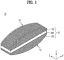
- FIG. 1 is a perspective view schematically illustrating a spinal cage according to an embodiment of the present disclosure.
- a spinal cage 10 according to an embodiment of the present disclosure includes a bone support portion 13, a base portion 15, and a sidewall portion 17.
- the bone support portion 13 is disposed between a first vertebra at an upper side and a second vertebra at a lower side, which neighbor each other, to support the first vertebra.
- the bone support portion 13 may have a mesh-like form.
- the base portion 15 is positioned at a lower side of the bone support portion 13 and disposed between the first vertebra and the second vertebra to come in contact with the second vertebra. Also, the base portion 15 may have a mesh-like form.
- the sidewall portion 17 is connected to the bone support portion 13 and the base portion 15 between the bone support portion 13 and the base portion 15 and serves to support the bone support portion 13 based on the base portion 15.
- the sidewall portion 17 has an upper side end connected to an edge of the bone support portion 13. Also, a lower side end of the sidewall portion 17 is connected to an edge of the base portion 15 to support the bone support portion 13 relative to the base portion 15.
- the sidewall portion 17 includes an elastic band 200 having elasticity and inelastic bands 110 and 120 having relatively lower elasticity than the elastic band 200 or no elasticity.
- the sidewall portion 17 may include the single elastic band 200 and the two inelastic bands 110 and 120.
- the two inelastic bands 110 and 120 are a first inelastic band 110 and a second inelastic band 120, which are only differentiated for convenience of description and are substantially the same.
- the first inelastic band 110 has an upper side connected to the edge of the bone support portion 13 and a lower side connected to the elastic band 200.
- the second inelastic band 120 has an upper side connected to the elastic band 200 and a lower side connected to the edge of the base portion 15.
- the elastic band 200 is positioned between the first inelastic band 110 and the second inelastic band 120.
- the elastic band 200 may be elastically deformed corresponding to a pressure between the first vertebra and the second vertebra.
- the sidewall portion 17 may have a form in which the first inelastic band 110 is positioned at an upper side and the second inelastic band 120 is positioned at a lower side while the single elastic band 200 is present therebetween or may also have a form which can be seen from FIG. 2 .
- FIG. 2 is a lateral view schematically illustrating another exemplary form of the spinal cage according to an embodiment of the present disclosure.
- a sidewall portion 17' includes a plurality of inelastic bands 100 and a plurality of elastic bands 200.
- the plurality of inelastic bands 100 and the plurality of elastic bands 200 may be alternately arranged with each other in a vertical direction as can be seen from FIG. 2 and help elastically absorb pressure between the vertebrae.
- FIGS. 3A and 3B in addition to FIG. 1 , for description of a cross-sectional shape of the sidewall portion.
- FIGS. 3A and 3B are plan views schematically illustrating the cross-section of the sidewall portion of the spinal cage according to an embodiment of the present disclosure.
- the elastic band 200 may have a form in which a cross-sectional thickness gradually increases from a center of the elastic band 200 toward an edge thereof, that is, toward the first inelastic band 110 or the second inelastic band 120.
- a thickness of the center of the elastic band 200 may be formed to be smaller than a thickness of an edge thereof.
- the cross-sectional shape of the elastic band 200 a shape in which one side is formed to be concave as illustrated in FIG. 3A is possible, and as the lateral cross-sectional shape of the elastic band 200, a shape in which both sides are formed to be concave as in a concave lens as illustrated in FIG. 3B is also possible.
- an elastic force of the elastic band 200 may be adjusted and formed by adjusting the thickness of the elastic band 200.
- first inelastic band 110 and the second inelastic band 120 may be formed so that elasticity gradually decreases from the elastic band 200 toward the bone support portion 13 or the base portion 15.
- the elasticity of the first inelastic band 110 and the second inelastic band 120 may gradually decrease due to the thickness thereof gradually increasing from the elastic band 200 toward the bone support portion 13 or the base portion 15.
- FIG. 4 is a view schematically illustrating an elastic unit body of the sidewall portion in the spinal cage according to an embodiment of the present disclosure
- FIG. 5 is a view schematically illustrating the elastic unit body in the spinal cage according to an embodiment of the present disclosure.
- a plurality of elastic unit bodies 400 are formed by being consecutively arranged on the elastic band 200 of the sidewall portion.
- the elastic band 200 may be an assembly formed by consecutive connection of the plurality of elastic unit bodies 400 which are elastically deformable corresponding to an external force.
- the elastic unit body 400 may be deformed according to an external force and may include a plurality of struts 410 connecting vertices 310 and crossing points 330 of a virtual hexahedron 300 indicated by dotted lines in the drawings.
- the crossing points 330 are points 330 provided at positions spaced apart at predetermined intervals 325 inward of the virtual hexahedron 300 at a face-centered 320 of the virtual hexahedron 300.
- the strut 410 connecting a single vertex 310 and a single crossing point 330 may have an arch shape or a curved shape.
- the strut 410 is connected in a form of being connected to another neighboring strut 410 via a vertex 310 or a crossing point 330.
- the elastic unit body 400 includes the plurality of struts 410.
- the elastic unit body 400 formed as above relieves pressure by causing deformation that bends the strut 410 when pressure is applied between vertebrae. Therefore, the elastic band 200 formed by the elastic unit bodies 400 being consecutively arranged may absorb the pressure applied between the vertebrae. Thus, it becomes possible to suppress an occurrence of subsidence into the vertebrae.
- the elastic unit body may also have a form illustrated in FIG. 6 .
- FIG. 6 is a view schematically illustrating a modified form of the elastic unit body in the spinal cage according to an embodiment of the present disclosure.
- An elastic unit body 400' which can be seen from FIG. 6 is substantially the same as the elastic unit body 400 described above with reference to FIG. 5 but is slightly different therefrom in terms of an arch shape of struts 410'.
- the struts 410 of the elastic unit body 400 which can be seen from FIG. 5 are formed in an arch shape that is convex toward an inner side of the virtual hexahedron 300 indicated by dotted lines.
- the struts 410' of the elastic unit body 400' which can be seen from FIG. 6 have an arch shape that is convex toward an outer side of a virtual hexahedron 300' indicated by dotted lines.
- the elastic unit body 400' includes a plurality of struts 410' connecting vertices 310' and crossing points 330' of the virtual hexahedron 300' indicated by dotted lines in FIG. 6 . Further, as described above, the strut 410' is connected in a form of being connected to another neighboring strut 410' via a vertex 310' or a crossing point 330'.
- the struts 410 and 410' can be elastically deformed corresponding to pressure between vertebrae, and thus the elastic unit bodies 400 and 400' can elastically absorb or relieve the pressure between the vertebrae.
- an elastic unit body having another form as follows is also possible.
- FIG. 7 is a view schematically illustrating another form of the elastic unit body in the spinal cage according to an embodiment of the present disclosure.
- An elastic unit body 600 which can be seen from FIG. 7 includes a base beam 610, an impact absorbing beam 620, and a support beam 630.
- the base beam 610 has one side end positioned on a vertex 510 of a virtual hexahedron 500 indicated by dotted lines in the drawing and is formed to have a predetermined length in a height direction.
- a plurality of base beams 610 are provided in a single elastic unit body 600.
- a plurality of base beams 610 are provided in a single elastic unit body 600.
- the base beams 610 are connected to other neighboring elastic unit bodies 600 and mostly serve to provide support. Therefore, the base beams 610 may allow an external force to be distributed to a plurality of elastic unit bodies 600.
- the impact absorbing beam 620 has one side end connected to the other side end 520 of the base beam 610, forms an acute angle relative to the base beam 610, and is formed to have a predetermined length.
- the impact absorbing beam 620 mostly serves to absorb impact corresponding to an external force in the elastic unit body 600.
- the support beam 630 has one side end 531 connected to the other side end of the impact absorbing beam 620 and the other side end 532 connected to the other side end of another impact absorbing beam 620 to have a predetermined length and has a longitudinal direction parallel to the base beam 610.
- the support beam 630 mostly serves to provide support in the elastic unit body 600.
- the base beam 610, the impact absorbing beam 620, and the support beam 630 are provided as a plurality of base beams 610, a plurality of impact absorbing beams 620, and a plurality of support beams 630 in a single elastic unit body 600.
- the elastic unit body 600 may relieve or absorb pressure between vertebrae.
- the elastic unit body 600 may relieve or absorb pressure between vertebrae by deformation that causes the base beams 610, the impact absorbing beams 620, and the support beams 630 to become close to one another.
- an elastic unit body having another form as follows is also possible.
- FIG. 8 is a view schematically illustrating still another form of the elastic unit body in the spinal cage according to an embodiment of the present disclosure.
- An elastic unit body 600 which can be seen from FIG. 8 includes a base beam 610, an impact absorbing beam 620, a support beam 630, and a torsion beam 640.
- the base beam 610 has one side end positioned on a vertex 510 of a virtual hexahedron 500 indicated by dotted lines in the drawing and is formed to have a predetermined length in a height direction.
- a plurality of base beams 610 are provided in a single elastic unit body 600.
- the base beams 610 are connected to other neighboring elastic unit bodies 600 and mostly serve to provide support. Therefore, the base beams 610 may allow an external force to be distributed to a plurality of elastic unit bodies 600.
- the impact absorbing beam 620 has one side end connected to the other side end 520 of the base beam 610, forms an acute angle relative to the base beam 610, and is formed to have a predetermined length.
- the impact absorbing beam 620 mostly serves to absorb impact corresponding to an external force in the elastic unit body 600.
- the support beam 630 has one side end 531 connected to the other side end of the impact absorbing beam 620 and the other side end 532 connected to the other side end of another impact absorbing beam 620 to have a predetermined length and has a longitudinal direction parallel to the base beam 610.
- the support beam 630 mostly serves to provide support in the elastic unit body 600.
- the torsion beam 640 is formed to have a predetermined length in a direction perpendicular to a longitudinal direction of the base beam 610 or the longitudinal direction of the support beam 630. Also, the torsion beam 640 is formed in a form in which one side end is connected to the other side end 520 of the base beam 610 and the other side end is connected to the other side end 520 of another neighboring base beam 610 or a form in which one side end is connected to the one side end 531 of the support beam 630 and the other side end is connected to the other side end 532 of another support beam 630.
- the elastic unit body 600 may relieve or absorb pressure between vertebrae.
- the elastic unit body 600 may relieve or absorb pressure between vertebrae by deformation that causes the base beams 610, the impact absorbing beams 620, and the support beams 630 to become close to one another.
- the torsion beam 640 may suppress or mitigate distortion of the elastic unit body 600 due to an external force.
- the base beam 610, the impact absorbing beam 620, the support beam 630, and the torsion beam 640 are provided as a plurality of base beams 610, a plurality of impact absorbing beams 620, a plurality of support beams 630, and a plurality of torsion beams 640 in a single elastic unit body 600.
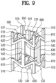
- an elastic unit body which can be seen from FIG. 9 is also possible.
- FIG. 9 is a view schematically illustrating an applied form of the elastic unit body in the spinal cage according to an embodiment of the present disclosure.
- An elastic unit body 600 which can be seen from FIG. 9 includes a base beam 610, an impact absorbing beam 620, and a support beam 630.
- the base beam 610 has one side end positioned on a vertex 510 of a virtual hexahedron 500 indicated by dotted lines and is formed to have a predetermined length in a height direction.
- one side end of a base beam 650 may be positioned at a face-centered 541 of an upper side surface or a lower side surface in the virtual hexahedron 500 indicated by dotted lines.
- another base beam 650 is provided at a lower side perpendicular to the above base beam 650 while a predetermined interval apart therefrom and has one side end positioned at the face-centered 541 of the lower side surface.
- the base beams 610 and 650 are provided as a plurality of base beams 610 and 650 in a single elastic unit body 600.
- the base beams 610 and 650 are connected to other neighboring elastic unit bodies 600 and mostly serve to provide support. Therefore, the base beams 610 and 650 may allow an external force to be distributed to a plurality of elastic unit bodies 600.
- the impact absorbing beam 620 has one side end connected to the other side end 520 of the base beam 610, forms an acute angle relative to the base beam 610, and is formed to have a predetermined length.
- the impact absorbing beam 620 mostly serves to absorb impact corresponding to an external force in the elastic unit body 600.
- the support beam 630 has one side end 531 connected to the other side end of the impact absorbing beam 620 and the other side end 532 connected to the other side end of another impact absorbing beam 620 to have a predetermined length and has a longitudinal direction parallel to the base beam 610.
- the support beam 630 mostly serves to provide support in the elastic unit body 600.
- the elastic unit body 600 which can be seen from FIG. 9 may also relieve or absorb pressure between vertebrae.
- the elastic unit body 600 may relieve or absorb pressure between vertebrae by deformation that causes the base beams 610, the impact absorbing beams 620, and the support beams 630 to become close to one another.
- the overall stiffness of the spinal cage can be formed to be lower than bone stiffness, and pressure between vertebrae may be absorbed or relieved to suppress an occurrence of subsidence.
Landscapes
- Health & Medical Sciences (AREA)
- Engineering & Computer Science (AREA)
- Biomedical Technology (AREA)
- Neurology (AREA)
- Orthopedic Medicine & Surgery (AREA)
- Cardiology (AREA)
- Oral & Maxillofacial Surgery (AREA)
- Transplantation (AREA)
- Heart & Thoracic Surgery (AREA)
- Vascular Medicine (AREA)
- Life Sciences & Earth Sciences (AREA)
- Animal Behavior & Ethology (AREA)
- General Health & Medical Sciences (AREA)
- Public Health (AREA)
- Veterinary Medicine (AREA)
- Prostheses (AREA)
Abstract
Description
- The present disclosure relates to a spinal cage inserted between vertebrae to support the vertebrae.
- Intervertebral discs serve as joints, and a nucleus pulposus located in the center of each disc changes its position and shape with movement of the spine, thereby playing an important role of minimizing impact applied to the spine.
- As a method of treating a disease involving a disc, there is a method of treatment in which a disc between damaged vertebrae is removed, and then a space between two adjacent vertebrae is replaced with a prosthetic material such as a cage. The cage helps restore an original distance between two adjacent vertebral bodies, which is an original height of the intervertebral disc, to restore the functions of the spine.
- The cage has a solid structure made of a metal material such as titanium or a titanium alloy, and sometimes, a problem occurs in which, after the cage is inserted between a vertebra and a neighboring vertebra and surgery is completed, surfaces of the vertebra and the neighboring vertebra that face each other subside due to an upper surface and a lower surface of the cage.
- That is, there is a problem in which, when pressure and impact according to a patient's weight and posture changes are not properly absorbed, an upper side surface or a lower side surface of a cage inserted between a vertebra and another neighboring vertebra subsides into the vertebrae.
- (Patent Document 1)
Korean Patent Publication no. 10-2016-0128236 - The present disclosure provides a spinal cage which can suppress subsidence of a spinal cage inserted between vertebrae into the vertebrae.
- One embodiment of the present disclosure provides a spinal cage including: a bone support portion disposed between a first vertebra at an upper side and a second vertebra at a lower side, which neighbor each other, to support the first vertebra; a base portion positioned at a lower side of the bone support portion and disposed between the first vertebra and the second vertebra to come in contact with the second vertebra; and a sidewall portion which has an upper side end connected to an edge of the bone support portion and a lower side end connected to an edge of the base portion to support the bone support portion relative to the base portion and which includes an elastic band having elasticity and inelastic bands having relatively lower elasticity than the elastic band or no elasticity.
- Here, in the sidewall portion, the inelastic bands may include a first inelastic band which has an upper side connected to the edge of the bone support portion and a lower side connected to the elastic band and a second inelastic band which has an upper side connected to the elastic band and a lower side connected to the edge of the base portion, and the elastic band may be positioned between the first inelastic band and the second inelastic band and be elastically deformable corresponding to a pressure between the first vertebra and the second vertebra.
- Here, the elastic band may have a form in which a cross-sectional thickness gradually increases from a center of the elastic band toward an edge thereof.
- Here, the first inelastic band and the second inelastic band may be formed so that elasticity gradually decreases from the elastic band toward the bone support portion or the base portion.
- Here, the elastic band may be an assembly formed by consecutive connection of a plurality of elastic unit bodies which are elastically deformable corresponding to an external force.
- Here, the elastic unit body may be deformable according to the external force and may include a plurality of struts connecting vertices and crossing points of a virtual hexahedron, and the crossing points may be points provided at positions spaced apart at predetermined intervals inward of the virtual hexahedron at a face-centered of the virtual hexahedron.
- Here, the strut of the elastic unit body may have an arch shape or a curved shape.
- Here, the elastic unit body may include a base beam which has one side end positioned on a vertex of a virtual hexahedron and is formed to have a predetermined length in a height direction, an impact absorbing beam which has one side end connected to the other side end of the base beam, forms an acute angle relative to the base beam, and is formed to have a predetermined length, and a support beam which has one side end connected to the other side end of the impact absorbing beam and the other side end connected to the other side end of another impact absorbing beam to have a predetermined length and which has a longitudinal direction parallel to the base beam.
- Here, the elastic unit body may include a base beam which has one side end positioned on a vertex of a virtual hexahedron and is formed to have a predetermined length in a height direction, an impact absorbing beam which has one side end connected to the other side end of the base beam, forms an acute angle relative to the base beam, and is formed to have a predetermined length, a support beam which has one side end connected to the other side end of the impact absorbing beam and the other side end connected to the other side end of another impact absorbing beam to have a predetermined length and which has a longitudinal direction parallel to the base beam, and a torsion beam formed to have a predetermined length in a direction perpendicular to a longitudinal direction of the base beam or the longitudinal direction of the support beam, wherein the torsion beam has one side end connected to the other side end of the base beam and the other side end connected to the other side end of another base beam or has one side end connected to the one side end of the support beam and the other side end connected to the other side end of another support beam.
- A spinal cage according to an embodiment of the present disclosure has an effect of relieving pressure between vertebrae and suppressing an occurrence of subsidence.
-
-
FIG. 1 is a perspective view schematically illustrating a spinal cage according to an embodiment of the present disclosure. -
FIG. 2 is a lateral view schematically illustrating another exemplary form of the spinal cage according to an embodiment of the present disclosure. -
FIGS. 3A and3B are plan views schematically illustrating a cross-section of a sidewall portion of the spinal cage according to an embodiment of the present disclosure. -
FIG. 4 is a view schematically illustrating an elastic unit body of the sidewall portion in the spinal cage according to an embodiment of the present disclosure. -
FIG. 5 is a view schematically illustrating the elastic unit body in the spinal cage according to an embodiment of the present disclosure. -
FIG. 6 is a view schematically illustrating a modified form of the elastic unit body in the spinal cage according to an embodiment of the present disclosure. -
FIG. 7 is a view schematically illustrating another form of the elastic unit body in the spinal cage according to an embodiment of the present disclosure. -
FIG. 8 is a view schematically illustrating still another form of the elastic unit body in the spinal cage according to an embodiment of the present disclosure. -
FIG. 9 is a view schematically illustrating an applied form of the elastic unit body in the spinal cage according to an embodiment of the present disclosure. - Hereinafter, exemplary embodiments will be described with reference to the accompanying drawings to facilitate understanding of the present disclosure.
- Since various modifications may be made to the present disclosure and the present disclosure may have various embodiments, specific embodiments illustrated in the drawings will be described in detail. However, this does not limit the present disclosure to the specific embodiments, and all modifications, equivalents, and/or substitutes included in the spirit and technical scope of the present disclosure should be construed as belonging to the present disclosure.
- Terms such as "first" and "second" may be used to describe various elements, but the elements are not limited by the terms. The terms are only used for the purpose of distinguishing one element from another element. For example, a first element may be referred to as a second element while not departing from the scope of the present disclosure, and likewise, a second element may also be referred to as a first element. The term "and/or" includes a combination of a plurality of associated listed items or any one item among the plurality of associated listed items.
- When it is mentioned that a certain element is "connected" or "linked" to another element, although the certain element may be directly connected or linked to the other element, it should be understood that another element may be present therebetween. On the other hand, when it is mentioned that a certain element is "directly connected" or "directly linked" to another element, it should be understood that other elements are not present therebetween.
- Terms used in the application are merely used to describe particular embodiments and are not intended to limit the present disclosure. A singular expression includes a plural expression unless the context clearly indicates otherwise. In the application, terms such as "include" or "have" should be understood as specifying that features, number, steps, operations, elements, components, or combinations thereof are present and not as precluding the possibility of the presence or addition of one or more other features, numbers, steps, operations, elements, components, or combinations thereof in advance.
- Unless otherwise defined, all terms including technical or scientific terms used herein have the same meaning as commonly understood by one of ordinary skill in the art to which the present disclosure pertains. Terms, such as those defined in commonly used dictionaries, should be construed as having a meaning that is consistent with their meaning in the context of the relevant art and are not to be construed in an idealized or overly formal sense unless expressly so defined herein.
- Hereinafter, exemplary embodiments of the present disclosure will be described in more detail with reference to the accompanying drawings. In describing the present disclosure, in order to facilitate overall understanding, the same elements will be denoted by the same reference numerals throughout the drawings and repeated descriptions thereof will be omitted.
-
FIG. 1 is a perspective view schematically illustrating a spinal cage according to an embodiment of the present disclosure. Referring toFIG. 1 , aspinal cage 10 according to an embodiment of the present disclosure includes abone support portion 13, abase portion 15, and asidewall portion 17. - The
bone support portion 13 is disposed between a first vertebra at an upper side and a second vertebra at a lower side, which neighbor each other, to support the first vertebra. Thebone support portion 13 may have a mesh-like form. - The
base portion 15 is positioned at a lower side of thebone support portion 13 and disposed between the first vertebra and the second vertebra to come in contact with the second vertebra. Also, thebase portion 15 may have a mesh-like form. - The
sidewall portion 17 is connected to thebone support portion 13 and thebase portion 15 between thebone support portion 13 and thebase portion 15 and serves to support thebone support portion 13 based on thebase portion 15. - That is, as can be seen from the drawing, the
sidewall portion 17 has an upper side end connected to an edge of thebone support portion 13. Also, a lower side end of thesidewall portion 17 is connected to an edge of thebase portion 15 to support thebone support portion 13 relative to thebase portion 15. - The
sidewall portion 17 includes anelastic band 200 having elasticity andinelastic bands elastic band 200 or no elasticity. - As can be seen from
FIG. 1 , thesidewall portion 17 may include the singleelastic band 200 and the twoinelastic bands inelastic bands inelastic band 110 and a secondinelastic band 120, which are only differentiated for convenience of description and are substantially the same. - The first
inelastic band 110 has an upper side connected to the edge of thebone support portion 13 and a lower side connected to theelastic band 200. - The second
inelastic band 120 has an upper side connected to theelastic band 200 and a lower side connected to the edge of thebase portion 15. - Also, the
elastic band 200 is positioned between the firstinelastic band 110 and the secondinelastic band 120. Theelastic band 200 may be elastically deformed corresponding to a pressure between the first vertebra and the second vertebra. - In this way, the
sidewall portion 17 may have a form in which the firstinelastic band 110 is positioned at an upper side and the secondinelastic band 120 is positioned at a lower side while the singleelastic band 200 is present therebetween or may also have a form which can be seen fromFIG. 2 . -
FIG. 2 is a lateral view schematically illustrating another exemplary form of the spinal cage according to an embodiment of the present disclosure. - Referring to
FIG. 2 , a sidewall portion 17' includes a plurality ofinelastic bands 100 and a plurality ofelastic bands 200. - Here, the plurality of
inelastic bands 100 and the plurality ofelastic bands 200 may be alternately arranged with each other in a vertical direction as can be seen fromFIG. 2 and help elastically absorb pressure between the vertebrae. - Also, further reference will be made to
FIGS. 3A and3B , in addition toFIG. 1 , for description of a cross-sectional shape of the sidewall portion. -
FIGS. 3A and3B are plan views schematically illustrating the cross-section of the sidewall portion of the spinal cage according to an embodiment of the present disclosure. - As can be seen from
FIGS. 1 and3A , theelastic band 200 may have a form in which a cross-sectional thickness gradually increases from a center of theelastic band 200 toward an edge thereof, that is, toward the firstinelastic band 110 or the secondinelastic band 120. - In other words, a thickness of the center of the
elastic band 200 may be formed to be smaller than a thickness of an edge thereof. - Therefore, as the cross-sectional shape of the
elastic band 200, a shape in which one side is formed to be concave as illustrated inFIG. 3A is possible, and as the lateral cross-sectional shape of theelastic band 200, a shape in which both sides are formed to be concave as in a concave lens as illustrated inFIG. 3B is also possible. - In this way, an elastic force of the
elastic band 200 may be adjusted and formed by adjusting the thickness of theelastic band 200. - Meanwhile, the first
inelastic band 110 and the secondinelastic band 120 may be formed so that elasticity gradually decreases from theelastic band 200 toward thebone support portion 13 or thebase portion 15. - For example, the elasticity of the first
inelastic band 110 and the secondinelastic band 120 may gradually decrease due to the thickness thereof gradually increasing from theelastic band 200 toward thebone support portion 13 or thebase portion 15. - For reference, such differences in the thicknesses of different portions of the
elastic band 200 may also be applied to the form of theelastic bands 200 of the sidewall portion 17' described above with reference toFIG. 2 . -
FIG. 4 is a view schematically illustrating an elastic unit body of the sidewall portion in the spinal cage according to an embodiment of the present disclosure, andFIG. 5 is a view schematically illustrating the elastic unit body in the spinal cage according to an embodiment of the present disclosure. - Referring to
FIGS. 4 and5 , as illustrated inFIG. 4 , a plurality ofelastic unit bodies 400 are formed by being consecutively arranged on theelastic band 200 of the sidewall portion. - That is, the
elastic band 200 may be an assembly formed by consecutive connection of the plurality ofelastic unit bodies 400 which are elastically deformable corresponding to an external force. - Here, the
elastic unit body 400 may be deformed according to an external force and may include a plurality ofstruts 410 connectingvertices 310 and crossingpoints 330 of avirtual hexahedron 300 indicated by dotted lines in the drawings. - Here, the crossing points 330 are
points 330 provided at positions spaced apart atpredetermined intervals 325 inward of thevirtual hexahedron 300 at a face-centered 320 of thevirtual hexahedron 300. - Also, in the
elastic unit body 400, thestrut 410 connecting asingle vertex 310 and asingle crossing point 330 may have an arch shape or a curved shape. Thestrut 410 is connected in a form of being connected to another neighboringstrut 410 via avertex 310 or acrossing point 330. Theelastic unit body 400 includes the plurality ofstruts 410. - The
elastic unit body 400 formed as above relieves pressure by causing deformation that bends thestrut 410 when pressure is applied between vertebrae. Therefore, theelastic band 200 formed by theelastic unit bodies 400 being consecutively arranged may absorb the pressure applied between the vertebrae. Thus, it becomes possible to suppress an occurrence of subsidence into the vertebrae. - Also, the elastic unit body may also have a form illustrated in
FIG. 6 . -
FIG. 6 is a view schematically illustrating a modified form of the elastic unit body in the spinal cage according to an embodiment of the present disclosure. - An elastic unit body 400' which can be seen from
FIG. 6 is substantially the same as theelastic unit body 400 described above with reference toFIG. 5 but is slightly different therefrom in terms of an arch shape of struts 410'. - That is, the
struts 410 of theelastic unit body 400 which can be seen fromFIG. 5 are formed in an arch shape that is convex toward an inner side of thevirtual hexahedron 300 indicated by dotted lines. Also, the struts 410' of the elastic unit body 400' which can be seen fromFIG. 6 have an arch shape that is convex toward an outer side of a virtual hexahedron 300' indicated by dotted lines. - Also, the elastic unit body 400' includes a plurality of struts 410' connecting vertices 310' and crossing points 330' of the virtual hexahedron 300' indicated by dotted lines in
FIG. 6 . Further, as described above, the strut 410' is connected in a form of being connected to another neighboring strut 410' via a vertex 310' or a crossing point 330'. - In this way, by the
strut 410 having an arch shape that is convex toward the inside as can be seen fromFIG. 5 or the strut 410' having an arch shape that is convex toward the outside as can be seen fromFIG. 6 , thestruts 410 and 410' can be elastically deformed corresponding to pressure between vertebrae, and thus theelastic unit bodies 400 and 400' can elastically absorb or relieve the pressure between the vertebrae. - Meanwhile, an elastic unit body having another form as follows is also possible.
-
FIG. 7 is a view schematically illustrating another form of the elastic unit body in the spinal cage according to an embodiment of the present disclosure. - An
elastic unit body 600 which can be seen fromFIG. 7 includes abase beam 610, animpact absorbing beam 620, and asupport beam 630. - Here, the
base beam 610 has one side end positioned on avertex 510 of avirtual hexahedron 500 indicated by dotted lines in the drawing and is formed to have a predetermined length in a height direction. - A plurality of
base beams 610 are provided in a singleelastic unit body 600. - A plurality of
base beams 610 are provided in a singleelastic unit body 600. The base beams 610 are connected to other neighboringelastic unit bodies 600 and mostly serve to provide support. Therefore, the base beams 610 may allow an external force to be distributed to a plurality ofelastic unit bodies 600. - Also, as can be seen from the drawing, the
impact absorbing beam 620 has one side end connected to the other side end 520 of thebase beam 610, forms an acute angle relative to thebase beam 610, and is formed to have a predetermined length. Theimpact absorbing beam 620 mostly serves to absorb impact corresponding to an external force in theelastic unit body 600. - The
support beam 630 has oneside end 531 connected to the other side end of theimpact absorbing beam 620 and the other side end 532 connected to the other side end of anotherimpact absorbing beam 620 to have a predetermined length and has a longitudinal direction parallel to thebase beam 610. Thesupport beam 630 mostly serves to provide support in theelastic unit body 600. - Also, the
base beam 610, theimpact absorbing beam 620, and thesupport beam 630 are provided as a plurality ofbase beams 610, a plurality ofimpact absorbing beams 620, and a plurality ofsupport beams 630 in a singleelastic unit body 600. - As an angle between the
base beam 610 and theimpact absorbing beam 620 changes when pressure is applied between vertebrae, theelastic unit body 600 may relieve or absorb pressure between vertebrae. Alternatively, theelastic unit body 600 may relieve or absorb pressure between vertebrae by deformation that causes the base beams 610, theimpact absorbing beams 620, and the support beams 630 to become close to one another. - Also, an elastic unit body having another form as follows is also possible.
-
FIG. 8 is a view schematically illustrating still another form of the elastic unit body in the spinal cage according to an embodiment of the present disclosure. Anelastic unit body 600 which can be seen fromFIG. 8 includes abase beam 610, animpact absorbing beam 620, asupport beam 630, and atorsion beam 640. - The
base beam 610 has one side end positioned on avertex 510 of avirtual hexahedron 500 indicated by dotted lines in the drawing and is formed to have a predetermined length in a height direction. - A plurality of
base beams 610 are provided in a singleelastic unit body 600. The base beams 610 are connected to other neighboringelastic unit bodies 600 and mostly serve to provide support. Therefore, the base beams 610 may allow an external force to be distributed to a plurality ofelastic unit bodies 600. - Also, as can be seen from the drawing, the
impact absorbing beam 620 has one side end connected to the other side end 520 of thebase beam 610, forms an acute angle relative to thebase beam 610, and is formed to have a predetermined length. Theimpact absorbing beam 620 mostly serves to absorb impact corresponding to an external force in theelastic unit body 600. - The
support beam 630 has oneside end 531 connected to the other side end of theimpact absorbing beam 620 and the other side end 532 connected to the other side end of anotherimpact absorbing beam 620 to have a predetermined length and has a longitudinal direction parallel to thebase beam 610. - The
support beam 630 mostly serves to provide support in theelastic unit body 600. - The
torsion beam 640 is formed to have a predetermined length in a direction perpendicular to a longitudinal direction of thebase beam 610 or the longitudinal direction of thesupport beam 630. Also, thetorsion beam 640 is formed in a form in which one side end is connected to the other side end 520 of thebase beam 610 and the other side end is connected to the other side end 520 of another neighboringbase beam 610 or a form in which one side end is connected to the oneside end 531 of thesupport beam 630 and the other side end is connected to the other side end 532 of anothersupport beam 630. - As an angle between the
base beam 610 and theimpact absorbing beam 620 changes when pressure is applied between vertebrae, theelastic unit body 600 may relieve or absorb pressure between vertebrae. Alternatively, theelastic unit body 600 may relieve or absorb pressure between vertebrae by deformation that causes the base beams 610, theimpact absorbing beams 620, and the support beams 630 to become close to one another. - Also, the
torsion beam 640 may suppress or mitigate distortion of theelastic unit body 600 due to an external force. - Further, the
base beam 610, theimpact absorbing beam 620, thesupport beam 630, and thetorsion beam 640 are provided as a plurality ofbase beams 610, a plurality ofimpact absorbing beams 620, a plurality of support beams 630, and a plurality oftorsion beams 640 in a singleelastic unit body 600. - Also, an elastic unit body which can be seen from
FIG. 9 is also possible. -
FIG. 9 is a view schematically illustrating an applied form of the elastic unit body in the spinal cage according to an embodiment of the present disclosure. Anelastic unit body 600 which can be seen fromFIG. 9 includes abase beam 610, animpact absorbing beam 620, and asupport beam 630. - The
base beam 610 has one side end positioned on avertex 510 of avirtual hexahedron 500 indicated by dotted lines and is formed to have a predetermined length in a height direction. - Also, one side end of a
base beam 650 may be positioned at a face-centered 541 of an upper side surface or a lower side surface in thevirtual hexahedron 500 indicated by dotted lines. - Also, another
base beam 650 is provided at a lower side perpendicular to theabove base beam 650 while a predetermined interval apart therefrom and has one side end positioned at the face-centered 541 of the lower side surface. - The base beams 610 and 650 are provided as a plurality of
base beams elastic unit body 600. The base beams 610 and 650 are connected to other neighboringelastic unit bodies 600 and mostly serve to provide support. Therefore, the base beams 610 and 650 may allow an external force to be distributed to a plurality ofelastic unit bodies 600. - Also, as can be seen from the drawing, the
impact absorbing beam 620 has one side end connected to the other side end 520 of thebase beam 610, forms an acute angle relative to thebase beam 610, and is formed to have a predetermined length. Theimpact absorbing beam 620 mostly serves to absorb impact corresponding to an external force in theelastic unit body 600. - The
support beam 630 has oneside end 531 connected to the other side end of theimpact absorbing beam 620 and the other side end 532 connected to the other side end of anotherimpact absorbing beam 620 to have a predetermined length and has a longitudinal direction parallel to thebase beam 610. - The
support beam 630 mostly serves to provide support in theelastic unit body 600. - In this way, as an angle between the
base beam 610 and theimpact absorbing beam 620 changes when pressure is applied between vertebrae, theelastic unit body 600 which can be seen fromFIG. 9 may also relieve or absorb pressure between vertebrae. Alternatively, theelastic unit body 600 may relieve or absorb pressure between vertebrae by deformation that causes the base beams 610, theimpact absorbing beams 620, and the support beams 630 to become close to one another. - As described above, according to a spinal cage according to the present disclosure, the overall stiffness of the spinal cage can be formed to be lower than bone stiffness, and pressure between vertebrae may be absorbed or relieved to suppress an occurrence of subsidence.
- As described above, detailed description of the present disclosure has been given using embodiments with reference to the accompanying drawings. However, since the above-described embodiments are only exemplary embodiments of the present disclosure, the present disclosure should not be understood as being limited to the above embodiments, and the scope of the present disclosure should be understood as being defined by the claims below and their equivalents.
[Description of reference numerals] 10: spinal cage 13: bone support portion 15: base portion 17: sidewall portion 100, 110, 120: inelastic band 200: elastic band 400, 600: elastic unit body 410, 410': strut 610: base beam 620: impact absorbing beam 630: support beam
Claims (10)
- A spinal cage comprising:a bone support portion disposed between a first vertebra at an upper side and a second vertebra at a lower side, which neighbor each other, to support the first vertebra;a base portion positioned at a lower side of the bone support portion and disposed between the first vertebra and the second vertebra to come in contact with the second vertebra; anda sidewall portion which has an upper side end connected to an edge of the bone support portion and a lower side end connected to an edge of the base portion to support the bone support portion relative to the base portion and which includes an elastic band having elasticity and inelastic bands having relatively lower elasticity than the elastic band or no elasticity.
- The spinal cage of claim 1, wherein:in the sidewall portion, the inelastic bands include a first inelastic band which has an upper side connected to the edge of the bone support portion and a lower side connected to the elastic band and a second inelastic band which has an upper side connected to the elastic band and a lower side connected to the edge of the base portion; andthe elastic band is positioned between the first inelastic band and the second inelastic band and is elastically deformable corresponding to a pressure between the first vertebra and the second vertebra.
- The spinal cage of claim 2, wherein the elastic band has a form in which a cross-sectional thickness gradually increases from a center of the elastic band toward an edge thereof.
- The spinal cage of claim 2, wherein the first inelastic band and the second inelastic band are formed so that elasticity gradually decreases from the elastic band toward the bone support portion or the base portion.
- The spinal cage of claim 4, wherein the elastic band is an assembly formed by consecutive connection of a plurality of elastic unit bodies which are elastically deformable corresponding to an external force.
- The spinal cage of claim 5, wherein:the elastic unit body is deformable according to the external force and includes a plurality of struts connecting vertices and crossing points of a virtual hexahedron; andthe crossing points are points provided at positions spaced apart at predetermined intervals inward of the virtual hexahedron at a face-centered of the virtual hexahedron.
- The spinal cage of claim 6, wherein the strut of the elastic unit body has an arch shape or a curved shape.
- The spinal cage of claim 5, wherein the elastic unit body includes:a base beam which has one side end positioned on a vertex of a virtual hexahedron and is formed to have a predetermined length in a height direction;an impact absorbing beam which has one side end connected to the other side end of the base beam, forms an acute angle relative to the base beam, and is formed to have a predetermined length; anda support beam which has one side end connected to the other side end of the impact absorbing beam and the other side end connected to the other side end of another impact absorbing beam to have a predetermined length and which has a longitudinal direction parallel to the base beam.
- The spinal cage of claim 5, wherein the elastic unit body includes:a base beam which has one side end positioned on a vertex of a virtual hexahedron and is formed to have a predetermined length in a height direction;an impact absorbing beam which has one side end connected to the other side end of the base beam, forms an acute angle relative to the base beam, and is formed to have a predetermined length;a support beam which has one side end connected to the other side end of the impact absorbing beam and the other side end connected to the other side end of another impact absorbing beam to have a predetermined length and which has a longitudinal direction parallel to the base beam, anda torsion beam formed to have a predetermined length in a direction perpendicular to a longitudinal direction of the base beam or the longitudinal direction of the support beam,wherein the torsion beam has one side end connected to the other side end of the base beam and the other side end connected to the other side end of another base beam or has one side end connected to the one side end of the support beam and the other side end connected to the other side end of another support beam.
- A spinal cage comprising:a bone support portion disposed between a first vertebra at an upper side and a second vertebra at a lower side, which neighbor each other, to support the first vertebra;a base portion positioned at a lower side of the bone support portion and disposed between the first vertebra and the second vertebra to come in contact with the second vertebra; anda sidewall portion which includes a plurality of elastic bands and inelastic bands alternately arranged with each other in a vertical direction between the bone support portion and the base portion, wherein the elastic bands have elasticity, and the inelastic bands have relatively lower elasticity than the elastic bands or no elasticity.
Applications Claiming Priority (2)
| Application Number | Priority Date | Filing Date | Title |
|---|---|---|---|
| KR1020200085467A KR102422248B1 (en) | 2020-07-10 | 2020-07-10 | Intervertebral Cage |
| PCT/KR2021/006309 WO2022010093A1 (en) | 2020-07-10 | 2021-05-21 | Vertebral cage |
Publications (3)
| Publication Number | Publication Date |
|---|---|
| EP4140452A1 true EP4140452A1 (en) | 2023-03-01 |
| EP4140452A4 EP4140452A4 (en) | 2024-05-29 |
| EP4140452B1 EP4140452B1 (en) | 2026-04-22 |
Family
ID=79553266
Family Applications (1)
| Application Number | Title | Priority Date | Filing Date |
|---|---|---|---|
| EP21837600.2A Active EP4140452B1 (en) | 2020-07-10 | 2021-05-21 | Vertebral cage |
Country Status (4)
| Country | Link |
|---|---|
| US (1) | US12419757B2 (en) |
| EP (1) | EP4140452B1 (en) |
| KR (1) | KR102422248B1 (en) |
| WO (1) | WO2022010093A1 (en) |
Family Cites Families (21)
| Publication number | Priority date | Publication date | Assignee | Title |
|---|---|---|---|---|
| FR2709949B1 (en) * | 1993-09-14 | 1995-10-13 | Commissariat Energie Atomique | Intervertebral disc prosthesis. |
| US6673113B2 (en) | 2001-10-18 | 2004-01-06 | Spinecore, Inc. | Intervertebral spacer device having arch shaped spring elements |
| ATE398431T1 (en) * | 2001-08-24 | 2008-07-15 | Zimmer Gmbh | ARTIFICIAL DISC |
| US8696749B2 (en) * | 2002-04-25 | 2014-04-15 | Blackstone Medical, Inc. | Artificial intervertebral disc |
| BR0215928A (en) * | 2002-10-28 | 2005-08-09 | Mathys Medizinaltechnik Ag | Intervertebral disc prosthesis or artificial vertebra |
| CA2621154A1 (en) * | 2005-09-01 | 2007-03-08 | Spinal Kinetics, Inc. | Prosthetic intervertebral discs |
| US7927375B2 (en) * | 2008-09-12 | 2011-04-19 | Doty Keith L | Dynamic six-degrees-of-freedom intervertebral spinal disc prosthesis |
| WO2010080511A1 (en) | 2008-12-18 | 2010-07-15 | 4-Web Spine, Inc. | Truss implant |
| CN202211766U (en) * | 2011-04-11 | 2012-05-09 | 广州医学院第二附属医院 | Expansion-type vertebral interbody fusion cage |
| KR101326054B1 (en) * | 2011-09-23 | 2013-11-07 | 서울대학교산학협력단 | Spinal implant |
| US8287598B1 (en) * | 2011-12-05 | 2012-10-16 | TrueMotion Spine, Inc. | True spinal motion preserving, shock absorbing, intervertebral spinal disc prosthesis |
| US9241808B2 (en) * | 2012-08-27 | 2016-01-26 | Anthony Sabatino | Auxetic prosthetic implant |
| KR101757177B1 (en) | 2015-04-27 | 2017-07-14 | 주식회사 제노스 | Method for producing porous metal implant and porous metal implant manufactured thereby |
| DE102015110202B3 (en) * | 2015-06-25 | 2016-06-09 | Heraeus Medical Gmbh | Kit for constructing a cage for spinal fusion and method therefor and corresponding cage and its use |
| TWI587847B (en) * | 2015-12-07 | 2017-06-21 | 財團法人工業技術研究院 | Implant device for osseous integration |
| WO2017106780A1 (en) | 2015-12-16 | 2017-06-22 | Nuvasive, Inc. | Porous spinal fusion implant |
| EP3592300B1 (en) * | 2017-03-10 | 2025-11-05 | Life Spine, Inc. | 3-d printed orthopedic implants |
| KR101806140B1 (en) * | 2017-06-29 | 2017-12-15 | 주식회사 멘티스로지텍 | Spinal implant with unit structure printed 3d printer |
| CN210644254U (en) * | 2018-06-12 | 2020-06-02 | 深圳市立心科学有限公司 | Interbody cage with buffer |
| AU2019213392B2 (en) * | 2018-08-09 | 2024-11-28 | Vb Spine Us Opco Llc | Interbody implants and optimization features thereof |
| CN213552651U (en) | 2019-05-13 | 2021-06-29 | 深圳市立心科学有限公司 | Self-adaptive intervertebral fusion device |
-
2020
- 2020-07-10 KR KR1020200085467A patent/KR102422248B1/en active Active
-
2021
- 2021-05-21 US US17/927,161 patent/US12419757B2/en active Active
- 2021-05-21 WO PCT/KR2021/006309 patent/WO2022010093A1/en not_active Ceased
- 2021-05-21 EP EP21837600.2A patent/EP4140452B1/en active Active
Also Published As
| Publication number | Publication date |
|---|---|
| WO2022010093A1 (en) | 2022-01-13 |
| KR102422248B1 (en) | 2022-07-18 |
| EP4140452A4 (en) | 2024-05-29 |
| EP4140452B1 (en) | 2026-04-22 |
| KR102422248B9 (en) | 2024-10-16 |
| US12419757B2 (en) | 2025-09-23 |
| US20230190486A1 (en) | 2023-06-22 |
| KR20220007351A (en) | 2022-01-18 |
Similar Documents
| Publication | Publication Date | Title |
|---|---|---|
| USRE48058E1 (en) | Intervertebral implant | |
| US8236055B2 (en) | Intervertebral prosthesis for supporting adjacent vertebral bodies enabling the creation of soft fusion and method | |
| JP4990296B2 (en) | Intervertebral disk replacement device | |
| US6572653B1 (en) | Vertebral implant adapted for posterior insertion | |
| USRE47470E1 (en) | Vertebral body placement and method for spanning a space formed upon removal of a vertebral body | |
| US7578849B2 (en) | Intervertebral implants and methods of use | |
| US8518117B2 (en) | Disc fusion implant | |
| JP4854775B2 (en) | Artificial intervertebral device with joint joint | |
| US6440169B1 (en) | Interspinous stabilizer to be fixed to spinous processes of two vertebrae | |
| US20090192617A1 (en) | Intervertebral Prosthetic Disc With Shock Absorbing Core Formed With Disc Springs | |
| US8313529B2 (en) | Total disc replacement with W-shaped spring elements | |
| EP3082653B1 (en) | Intervertebral spacer that dynamically promotes bone growth | |
| KR20060055297A (en) | Intervertebral Implant | |
| US7887590B2 (en) | Intervertebral disc prosthesis | |
| JP2008526459A (en) | Elastomeric disc prosthesis | |
| KR20130097206A (en) | Compliant implant | |
| US20120116512A1 (en) | Intervertebral disk prosthesis notably for cervical vertebrae | |
| CN210644254U (en) | Interbody cage with buffer | |
| EP2793759A1 (en) | Spinal implant | |
| US12419757B2 (en) | Spinal cage | |
| US20210100659A1 (en) | Device and method for correcting spinal deformities in patients | |
| KR20190060762A (en) | Interdental implant | |
| EP3915527B1 (en) | Artificial spinal disc | |
| CN119184925B (en) | A mechanically adaptive intervertebral fusion cage with variable stiffness | |
| WO2026083952A1 (en) | Interbody fixation device |
Legal Events
| Date | Code | Title | Description |
|---|---|---|---|
| STAA | Information on the status of an ep patent application or granted ep patent |
Free format text: STATUS: THE INTERNATIONAL PUBLICATION HAS BEEN MADE |
|
| PUAI | Public reference made under article 153(3) epc to a published international application that has entered the european phase |
Free format text: ORIGINAL CODE: 0009012 |
|
| STAA | Information on the status of an ep patent application or granted ep patent |
Free format text: STATUS: REQUEST FOR EXAMINATION WAS MADE |
|
| 17P | Request for examination filed |
Effective date: 20221123 |
|
| AK | Designated contracting states |
Kind code of ref document: A1 Designated state(s): AL AT BE BG CH CY CZ DE DK EE ES FI FR GB GR HR HU IE IS IT LI LT LU LV MC MK MT NL NO PL PT RO RS SE SI SK SM TR |
|
| DAV | Request for validation of the european patent (deleted) | ||
| DAX | Request for extension of the european patent (deleted) | ||
| A4 | Supplementary search report drawn up and despatched |
Effective date: 20240426 |
|
| RIC1 | Information provided on ipc code assigned before grant |
Ipc: A61F 2/30 20060101ALI20240422BHEP Ipc: A61F 2/44 20060101AFI20240422BHEP |
|
| GRAP | Despatch of communication of intention to grant a patent |
Free format text: ORIGINAL CODE: EPIDOSNIGR1 |
|
| STAA | Information on the status of an ep patent application or granted ep patent |
Free format text: STATUS: GRANT OF PATENT IS INTENDED |
|
| INTG | Intention to grant announced |
Effective date: 20251124 |
|
| GRAS | Grant fee paid |
Free format text: ORIGINAL CODE: EPIDOSNIGR3 |
|
| GRAA | (expected) grant |
Free format text: ORIGINAL CODE: 0009210 |
|
| STAA | Information on the status of an ep patent application or granted ep patent |
Free format text: STATUS: THE PATENT HAS BEEN GRANTED |
|
| AK | Designated contracting states |
Kind code of ref document: B1 Designated state(s): AL AT BE BG CH CY CZ DE DK EE ES FI FR GB GR HR HU IE IS IT LI LT LU LV MC MK MT NL NO PL PT RO RS SE SI SK SM TR |
|
| REG | Reference to a national code |
Ref country code: CH Ref legal event code: F10 Free format text: ST27 STATUS EVENT CODE: U-0-0-F10-F00 (AS PROVIDED BY THE NATIONAL OFFICE) Effective date: 20260422 Ref country code: GB Ref legal event code: FG4D |
|
| REG | Reference to a national code |
Ref country code: DE Ref legal event code: R096 Ref document number: 602021052743 Country of ref document: DE |