EP4140430A1 - Active control of surgical smoke evacuation - Google Patents
Active control of surgical smoke evacuation Download PDFInfo
- Publication number
- EP4140430A1 EP4140430A1 EP22191547.3A EP22191547A EP4140430A1 EP 4140430 A1 EP4140430 A1 EP 4140430A1 EP 22191547 A EP22191547 A EP 22191547A EP 4140430 A1 EP4140430 A1 EP 4140430A1
- Authority
- EP
- European Patent Office
- Prior art keywords
- nozzle
- valve
- smoke
- vacuum pressure
- suction
- Prior art date
- Legal status (The legal status is an assumption and is not a legal conclusion. Google has not performed a legal analysis and makes no representation as to the accuracy of the status listed.)
- Withdrawn
Links
- 239000000779 smoke Substances 0.000 title claims abstract description 114
- 238000004891 communication Methods 0.000 claims abstract description 12
- 239000012530 fluid Substances 0.000 claims abstract description 5
- 230000013011 mating Effects 0.000 claims description 20
- 230000004044 response Effects 0.000 claims description 7
- 230000008878 coupling Effects 0.000 claims description 4
- 238000010168 coupling process Methods 0.000 claims description 4
- 238000005859 coupling reaction Methods 0.000 claims description 4
- 230000000284 resting effect Effects 0.000 claims description 3
- 238000000034 method Methods 0.000 description 5
- 239000004606 Fillers/Extenders Substances 0.000 description 3
- 239000000463 material Substances 0.000 description 3
- 238000001356 surgical procedure Methods 0.000 description 3
- 230000003213 activating effect Effects 0.000 description 2
- 230000001112 coagulating effect Effects 0.000 description 2
- 239000003989 dielectric material Substances 0.000 description 2
- 230000006870 function Effects 0.000 description 2
- 238000012986 modification Methods 0.000 description 2
- 230000004048 modification Effects 0.000 description 2
- 239000004642 Polyimide Substances 0.000 description 1
- 238000003491 array Methods 0.000 description 1
- 230000008901 benefit Effects 0.000 description 1
- 210000004204 blood vessel Anatomy 0.000 description 1
- 239000006227 byproduct Substances 0.000 description 1
- 238000010276 construction Methods 0.000 description 1
- 238000013500 data storage Methods 0.000 description 1
- 230000000694 effects Effects 0.000 description 1
- 238000002156 mixing Methods 0.000 description 1
- 239000013618 particulate matter Substances 0.000 description 1
- 230000035515 penetration Effects 0.000 description 1
- 229920001721 polyimide Polymers 0.000 description 1
- 238000012545 processing Methods 0.000 description 1
- 238000005507 spraying Methods 0.000 description 1
- 239000012815 thermoplastic material Substances 0.000 description 1
- 230000004304 visual acuity Effects 0.000 description 1
- 238000012800 visualization Methods 0.000 description 1
- 238000003466 welding Methods 0.000 description 1
Images



Classifications
-
- A—HUMAN NECESSITIES
- A61—MEDICAL OR VETERINARY SCIENCE; HYGIENE
- A61B—DIAGNOSIS; SURGERY; IDENTIFICATION
- A61B18/00—Surgical instruments, devices or methods for transferring non-mechanical forms of energy to or from the body
- A61B18/04—Surgical instruments, devices or methods for transferring non-mechanical forms of energy to or from the body by heating
- A61B18/12—Surgical instruments, devices or methods for transferring non-mechanical forms of energy to or from the body by heating by passing a current through the tissue to be heated, e.g. high-frequency current
- A61B18/14—Probes or electrodes therefor
-
- A—HUMAN NECESSITIES
- A61—MEDICAL OR VETERINARY SCIENCE; HYGIENE
- A61B—DIAGNOSIS; SURGERY; IDENTIFICATION
- A61B18/00—Surgical instruments, devices or methods for transferring non-mechanical forms of energy to or from the body
- A61B18/04—Surgical instruments, devices or methods for transferring non-mechanical forms of energy to or from the body by heating
- A61B18/12—Surgical instruments, devices or methods for transferring non-mechanical forms of energy to or from the body by heating by passing a current through the tissue to be heated, e.g. high-frequency current
- A61B18/14—Probes or electrodes therefor
- A61B18/1485—Probes or electrodes therefor having a short rigid shaft for accessing the inner body through natural openings
-
- A—HUMAN NECESSITIES
- A61—MEDICAL OR VETERINARY SCIENCE; HYGIENE
- A61B—DIAGNOSIS; SURGERY; IDENTIFICATION
- A61B18/00—Surgical instruments, devices or methods for transferring non-mechanical forms of energy to or from the body
- A61B2018/00053—Mechanical features of the instrument of device
- A61B2018/00172—Connectors and adapters therefor
-
- A—HUMAN NECESSITIES
- A61—MEDICAL OR VETERINARY SCIENCE; HYGIENE
- A61B—DIAGNOSIS; SURGERY; IDENTIFICATION
- A61B18/00—Surgical instruments, devices or methods for transferring non-mechanical forms of energy to or from the body
- A61B2018/00053—Mechanical features of the instrument of device
- A61B2018/00172—Connectors and adapters therefor
- A61B2018/00178—Electrical connectors
-
- A—HUMAN NECESSITIES
- A61—MEDICAL OR VETERINARY SCIENCE; HYGIENE
- A61B—DIAGNOSIS; SURGERY; IDENTIFICATION
- A61B18/00—Surgical instruments, devices or methods for transferring non-mechanical forms of energy to or from the body
- A61B2018/00571—Surgical instruments, devices or methods for transferring non-mechanical forms of energy to or from the body for achieving a particular surgical effect
- A61B2018/00589—Coagulation
-
- A—HUMAN NECESSITIES
- A61—MEDICAL OR VETERINARY SCIENCE; HYGIENE
- A61B—DIAGNOSIS; SURGERY; IDENTIFICATION
- A61B18/00—Surgical instruments, devices or methods for transferring non-mechanical forms of energy to or from the body
- A61B2018/00571—Surgical instruments, devices or methods for transferring non-mechanical forms of energy to or from the body for achieving a particular surgical effect
- A61B2018/00601—Cutting
-
- A—HUMAN NECESSITIES
- A61—MEDICAL OR VETERINARY SCIENCE; HYGIENE
- A61B—DIAGNOSIS; SURGERY; IDENTIFICATION
- A61B18/00—Surgical instruments, devices or methods for transferring non-mechanical forms of energy to or from the body
- A61B2018/00636—Sensing and controlling the application of energy
- A61B2018/00666—Sensing and controlling the application of energy using a threshold value
- A61B2018/00678—Sensing and controlling the application of energy using a threshold value upper
-
- A—HUMAN NECESSITIES
- A61—MEDICAL OR VETERINARY SCIENCE; HYGIENE
- A61B—DIAGNOSIS; SURGERY; IDENTIFICATION
- A61B18/00—Surgical instruments, devices or methods for transferring non-mechanical forms of energy to or from the body
- A61B2018/00636—Sensing and controlling the application of energy
- A61B2018/00696—Controlled or regulated parameters
- A61B2018/00744—Fluid flow
-
- A—HUMAN NECESSITIES
- A61—MEDICAL OR VETERINARY SCIENCE; HYGIENE
- A61B—DIAGNOSIS; SURGERY; IDENTIFICATION
- A61B18/00—Surgical instruments, devices or methods for transferring non-mechanical forms of energy to or from the body
- A61B2018/00636—Sensing and controlling the application of energy
- A61B2018/00773—Sensed parameters
-
- A—HUMAN NECESSITIES
- A61—MEDICAL OR VETERINARY SCIENCE; HYGIENE
- A61B—DIAGNOSIS; SURGERY; IDENTIFICATION
- A61B18/00—Surgical instruments, devices or methods for transferring non-mechanical forms of energy to or from the body
- A61B2018/0091—Handpieces of the surgical instrument or device
-
- A—HUMAN NECESSITIES
- A61—MEDICAL OR VETERINARY SCIENCE; HYGIENE
- A61B—DIAGNOSIS; SURGERY; IDENTIFICATION
- A61B18/00—Surgical instruments, devices or methods for transferring non-mechanical forms of energy to or from the body
- A61B2018/00988—Means for storing information, e.g. calibration constants, or for preventing excessive use, e.g. usage, service life counter
-
- A—HUMAN NECESSITIES
- A61—MEDICAL OR VETERINARY SCIENCE; HYGIENE
- A61B—DIAGNOSIS; SURGERY; IDENTIFICATION
- A61B90/00—Instruments, implements or accessories specially adapted for surgery or diagnosis and not covered by any of the groups A61B1/00 - A61B50/00, e.g. for luxation treatment or for protecting wound edges
- A61B90/06—Measuring instruments not otherwise provided for
- A61B2090/064—Measuring instruments not otherwise provided for for measuring force, pressure or mechanical tension
-
- A—HUMAN NECESSITIES
- A61—MEDICAL OR VETERINARY SCIENCE; HYGIENE
- A61B—DIAGNOSIS; SURGERY; IDENTIFICATION
- A61B2218/00—Details of surgical instruments, devices or methods for transferring non-mechanical forms of energy to or from the body
- A61B2218/001—Details of surgical instruments, devices or methods for transferring non-mechanical forms of energy to or from the body having means for irrigation and/or aspiration of substances to and/or from the surgical site
- A61B2218/007—Aspiration
-
- A—HUMAN NECESSITIES
- A61—MEDICAL OR VETERINARY SCIENCE; HYGIENE
- A61B—DIAGNOSIS; SURGERY; IDENTIFICATION
- A61B2218/00—Details of surgical instruments, devices or methods for transferring non-mechanical forms of energy to or from the body
- A61B2218/001—Details of surgical instruments, devices or methods for transferring non-mechanical forms of energy to or from the body having means for irrigation and/or aspiration of substances to and/or from the surgical site
- A61B2218/007—Aspiration
- A61B2218/008—Aspiration for smoke evacuation
-
- A—HUMAN NECESSITIES
- A61—MEDICAL OR VETERINARY SCIENCE; HYGIENE
- A61B—DIAGNOSIS; SURGERY; IDENTIFICATION
- A61B90/00—Instruments, implements or accessories specially adapted for surgery or diagnosis and not covered by any of the groups A61B1/00 - A61B50/00, e.g. for luxation treatment or for protecting wound edges
- A61B90/90—Identification means for patients or instruments, e.g. tags
- A61B90/98—Identification means for patients or instruments, e.g. tags using electromagnetic means, e.g. transponders
Definitions
- the disclosure relates to surgical devices. More specifically, the disclosure relates to active control of handheld smoke evacuation electrosurgical pencils.
- Electrosurgical (ES) pencils are used in surgery, typically for cutting tissue and/or for coagulating blood vessels.
- An ES pencil usually includes a handpiece into which electrodes of various shapes and sizes may be placed.
- the ES pencil is coupled to an ES generator, such as Medtronic's Valleylab TM LS10 or FT10 generator, which supplies the electrode with a high frequency, typically radio frequency (RF) alternating current.
- RF radio frequency
- the ES generator may supply various waveforms suitable for achieving various surgical effects, such as cutting, coagulating, blending, spraying, fulgurating, and the like.
- ES pencil While using an ES pencil, smoke is often generated.
- An effective way to evacuate surgical smoke is to use an ES pencil with an integrated smoke evacuation nozzle in conjunction with a suction device and an ultra-low penetration air (ULPA) filter.
- ULPA ultra-low penetration air
- Conventional ES pencils rely on smoke evacuation shrouds attached to the ES pencil, which suction the smoke away via a suction device.
- Smoke shrouds are available either as an integrated part of the ES pencil or as a separate shroud attached to the ES pencil.
- a smoke nozzle situated near the pencil's electrode, draws the smoke plume into and through the pencil's body, through a long flexible hose, and finally into a powered suction device outside of the surgical field.
- this higher vacuum pressure may undesirably mechanically suck tissue into the inlet of the suction conduit if it comes in contact with the tissue.
- the disclosure provides an electrosurgical (ES) pencil having a handle housing and a smoke nozzle, which may be removable, integrated, and/or telescopic relative to a handle housing.
- the ES pencil includes an electrical plug configured to couple to an electrosurgical generator.
- the handle housing may have an ergonomic shape and have a slim cross-sectional area (e.g., having a height, width, or diameter of from about 10 mm to about 20 mm).
- the nozzle evacuates surgical smoke through the handle housing and through smoke evacuation tubing into a smoke evacuator.
- the smoke evacuation tubing may be corrugated to minimize kinking and to allow for free and natural movement of the ES pencil.
- the nozzle may be clear to aid with visualization of an electrode and its electrode tip.
- the nozzle also directs the smoke past a printed circuit board (PCB) coupled to a rocker switch to limit alternative current paths due to smoke intrusion into sensitive electronic components.
- PCB printed circuit board
- the PCB may have an over mold on the front and back of the pencil, as well as tape that covers the PCB to limit moisture ingress.
- a rocker switch may be disposed over the PCB and used to control the energy delivered by the ES pencil by engaging the pushbutton switches disposed on the PCB.
- the disclosure includes multiple embodiments, each of which includes multiple aspects. Various aspects of the embodiments are interchangeable among the disclosed aspects.
- an ES smoke evacuation pencil includes a handle housing having a proximal end portion and a distal end portion, the handle housing defining a lumen therethrough, a nozzle in fluid communication with the lumen, a pressure sensor configured to sense a vacuum pressure at the nozzle, a connector coupled to the distal end portion of the handle housing, the connector configured to couple to a suction source, and an electrode configured to couple to a source of electrosurgical energy.
- the ES pencil may further include a valve to reduce or remove the vacuum pressure at the nozzle when actuated.
- the valve may be actuated to an open position in response to a pressure signal measured by the pressure sensor exceeding a preset threshold.
- the pressure sensor may be integrated into the valve.
- the ES pencil may further include a motion sensor disposed on the nozzle.
- the motion sensor may transmit a motion signal to the suction source to initiate suction.
- the valve may include a cover to prevent actuation of the valve by an external force.
- the connector may include a mating sensor to sense a mating connection with the suction source.
- the active sensor may include a unique identifier.
- the connector may be configured for electrical communication between the pressure sensor and the suction source.
- the connector may include a mechanical interface to mate with a suction conduit having a counterpart mechanical interface.
- a surgical smoke evacuation system includes a smoke evacuator including a suction generator configured to create a vacuum pressure, an ES pencil, a suction conduit coupling a nozzle to the smoke evacuator, a valve configured to reduce the vacuum pressure from the nozzle of the ES pencil, a processor, and a memory.
- the ES pencil further includes a pressure sensor configured to sense vacuum pressure at the nozzle.
- the memory includes instructions stored thereon, which, when executed by the processor, cause the surgical smoke evacuation system to sense the vacuum pressure at the nozzle and actuate the valve to an open position based on the sensed pressure.
- the valve may open to reduce the vacuum pressure from the nozzle of the ES pencil in response to the sensed vacuum force being greater than a predetermined threshold.
- the smoke evacuation system may further include a motion sensor disposed on the nozzle.
- the instructions when executed by the processor, may further cause the system to sense a signal by the motion sensor indicating movement of the ES pencil and initiate suction by the smoke evacuator based on the sensed signal.
- the smoke evacuation system may further include a motion sensor disposed on the nozzle.
- the instructions when executed by the processor, may further cause the system to sense a signal by the motion sensor indicating that the ES pencil is at a resting position and stop suction by the smoke evacuator based on the sensed signal.
- the valve may include a cover to prevent actuation of the valve by an external force.
- the pressure sensor may be integrated into the valve.
- the instructions when executed by the processor, may further cause the system to dynamically adjust the vacuum pressure generated by the smoke evacuator based on the sensed vacuum pressure at the nozzle.
- the instructions when executed by the processor, may further cause the system to determine the nozzle is occluded based on the sensed signal and dynamically adjust the vacuum pressure generated by the smoke evacuator based on the determined occlusion.
- the instructions when executed by the processor, may further cause the system to determine whether the occlusion is removed based on the sensed signal and dynamically increase the vacuum pressure generated by the smoke evacuator based on the determination the occlusion was removed.
- the ES pencil may include a connector to couple to a suction source, where the connector includes a mating sensor to sense a mating connection with the suction source
- the surgical smoke evacuation system 100 generally includes a smoke evacuator 130, an ES pencil 200 ( FIG. 2 ), a suction conduit 140 connecting the ES pencil 200 to the smoke evacuator 130, and one or more valves 230a-230c configured to reduce the vacuum pressure from a nozzle 212 of the ES pencil 200.
- the smoke evacuator 130 includes a suction generator (e.g., suction generator 135 in FIGS. 4-8 ) that creates negative pressure having a set vacuum force for removing smoke during a surgical operation.
- the suction conduit 140 is connected to the ES pencil 200 at its distal end and to an inlet port 132 of the smoke evacuator 130 at its proximal end.
- the suction generator 135 may include one or more fans to create the negative pressure enabling smoke removal from a surgical site.
- the valves 230a-230c are configured to reduce the vacuum pressure from a nozzle 212 of the ES pencil 200 when actuated in an open position.
- the valves 230a-230c may be integrated into the ES pencil 200, the suction conduit 140, and/or the smoke evacuator 130.
- the valves 230a-230c may be in electrical communication with a pressure sensor 240 ( FIG. 2 ) of the ES pencil 200.
- the smoke evacuator 130 also includes a processor 190 and a memory 192. Instructions may be executed by the processor 190, which may include one or more digital signal processors (DSPs), general-purpose microprocessors, application-specific integrated circuits (ASICs), field programmable logic arrays (FPGAs), or other equivalent integrated or discrete logic circuitry. Accordingly, the term "processor” as used herein may refer to any of the foregoing structures or any other physical structure suitable for implementation of the described techniques. Also, the techniques could be fully implemented in one or more circuits or logic elements. It is contemplated that the processor 190 and memory 192 may be located in the smoke evacuator 130, the ES pencil 200, and/or in a remote computer system.
- DSPs digital signal processors
- ASICs application-specific integrated circuits
- FPGAs field programmable logic arrays
- the memory 192 includes instructions stored thereon which, when executed by the processor 190, cause the surgical smoke evacuation system 100 to sense the vacuum pressure at the nozzle 212, by the pressure sensor 240, and actuate the valves 230a-230c to an open position based on the sensed pressure.
- the described techniques may be implemented in hardware, software, firmware, or any combination thereof. If implemented in software, the functions may be stored as one or more instructions or code on a computer-readable medium and executed by a hardware-based processing unit.
- Computer-readable media may include non-transitory computer-readable media, which corresponds to a tangible medium such as data storage media (e.g., RAM, ROM, EEPROM, flash memory, or any other medium that can be used to store desired program code in the form of instructions or data structures and that can be accessed by a computer).
- an ES pencil 200 which includes a handle housing 210 formed from a thermoplastic material.
- the handle housing 210 includes an upper portion 210a and a lower portion 210b, which are secured to each other using any suitable method, e.g., ultrasonically welding, to secure internal components of the ES pencil 200.
- the handle housing 10 defines a lumen 210c therethrough.
- the ES pencil 200 also includes a nozzle 212 that may be removably or securely coupled within the housing 210 and an electrode 214 disposed within the nozzle 212.
- the nozzle 212 also defines a lumen 212a, which is in fluid communication with the lumen 210c.
- the nozzle 212 is formed from a dielectric material, such as polyimide, and provides for the suctioning of gaseous byproducts through the handle housing 210.
- the dielectric material of the nozzle 212 may be a transparent, substantially transparent, or translucent material configured to facilitate visual acuity in the surgical field.
- an opaque or substantially opaque material may also be used as such materials would not affect the operation of the device.
- the ES pencil 200 also includes a connector 222 (e.g., a swivel connector) coupling the nozzle 212 to the suction conduit 140.
- the nozzle 212 may also include a distal end portion 212b, which may be configured to couple to a nozzle extender attachment 213.
- the distal end portion 212b may have a plurality of ribs 212c for frictionally engaging the nozzle extender attachment 213. This allows the ES pencil 200 to have a longer nozzle 212 to use with a longer electrode 214 for deeper access.
- the ES pencil 200 further includes a pressure sensor 240 configured to sense vacuum pressure at the nozzle 212.
- the pressure sensor 240 may be a piezo sensor, a cold cathode sensor, a hot cathode sensor, a capacitive sensor, a pressure switch, and/or a Pirani vacuum pressure sensor.
- the pressure sensor 240 senses the vacuum pressure that is used to draw smoke from the surgical site.
- the ES pencil 200 may further include a valve 230a disposed on or proximate to the nozzle 212.
- the valve 230a is configured to reduce the vacuum pressure from a nozzle 212 when actuated in an open position.
- the valves 230a-230c may be used in conjunction with the pressure sensor 240 to dynamically control the vacuum pressure at the nozzle 212 of the ES pencil 200.
- the valves 230a-230c may be bleeder valves, flap valves, and/or any suitable type of valve.
- the valves 230a-230c may have an integrated pressure sensor 240. It is contemplated that the valve 230a-230c may be mechanically designed to open at a pre-determined pressure (e.g., by selection of spring force).
- the ES pencil 200 may further include a motion sensor 250 configured to sense the motion of the ES pencil 200 and activate the suction generator 135 based on the sensed motion.
- Smoke evacuators 130 may include a time limit control to prevent overuse of an air filter (not shown) configured to filter the air of smoke and other particulate matter.
- smoke evacuators 130 may include a timer that controls when suction is active, so the suction is not on continuously to increase the life span of the filter(s).
- the suction generator 135 and timer of the smoke evacuator 130 may be started when the ES pencil 200 is energized, i.e., in response to pressimg of an actuation pushbutton on the ES pencil 200.
- the motion sensor 250 is in electrical communication with the processor 190 ( FIG. 1 ).
- the motion sensor 250 may be an accelerometer, a gyroscope, or any other suitable sensor configured to measure movement and/or tilt of the ES pencil 200.
- the motion sensor 250 may be disposed on a distal end of the suction conduit 140 that turns on the suction generator 135 when the ES pencil 200 is being manipulated and a timer to turn it off when the ES pencil 200 is set down. In embodiments, the motion sensor 250 may be disposed anywhere on the ES pencil 200.
- the ES pencil 200 may further include a touch sensor 254 on the ES pencil 200 configured to activate the smoke evacuator 130.
- the touch sensor 254 is configured to sense contact when the ES pencil 200 is grabbed by the user, indicating an intent to use the ES pencil 200.
- the touch sensor 254 is located on a portion of the housing 210 of the ES pencil 200 where the surgeon normally grabs the ES pencil 200 for performing surgery.
- the touch sensor 254 is also in electrical communication with the processor 190.
- the connector 222 of the ES pencil 200 may further be configured for electrical communication between the pressure sensor and the suction source (e.g., smoke evacuator 130) to prevent a standard suction conduit from being used with the surgical smoke evacuation system 100 of FIG. 1 .
- This connector 222 may include a mating sensor 260 configured to sense a mating connection with the suction generator 135.
- the mating sensor 260 may include a unique identifier, which may be used by the processor to detect and confirm if the ES pencil 200 is mated with the correct suction generator 135.
- the mating sensor 260 may include a Radio Frequency Identification (RFID) sensor configured to send and receive the unique identifier to the processor 190 to enable mating of the ES pencil 200 with the smoke evacuator 130.
- RFID Radio Frequency Identification
- the smoke evacuator 130 may include an RFID tag (not shown) configured to be scanned by the RFID reader of the mating sensor 260 of the ES pencil 200.
- the connector 222 further may include a mechanical interface configured to mate with a suction conduit 140 having a counterpart mechanical interface.
- the mechanical interface may include an outer shape such as a triangular shape, or other suitable outer shape.
- the suction generator 135 of the smoke evacuator 130 may be limited to generating a lower vacuum (e.g., below about -15 kPa).
- FIGS. 4 and 5 illustrate a side cross-sectional view of the surgical smoke evacuation system 100.
- the ES pencil 200 may further include a cover 600 to prevent occlusion of the valve 230a when the valve 230a is in an open position.
- the valve cover 600 may be a mesh cover, or any other cover which permits the flow of air.
- the cover 600 may include a number of (e.g., two) inlets located a distance apart such that both inlets would not be easily covered, for example, by the pad of a single finger.
- the cover may include raised ridges with inlet holes in troughs would allow airflow even when covered, for example by by a finger.
- the processor 190 may control higher vacuum pressure with the pressure sensor 240 at the nozzle 212 ( FIG. 2 ) by enabling dynamic control of the vacuum pressure generated by the suction generator 135 of the smoke evacuator 130. If the nozzle 212 is occluded (e.g., by tissue 700 as in FIG. 5 ), then the processor 190 ( FIG. 1 ) may sense a vacuum at the nozzle 212 above a threshold, which may be about -15 kPa, and may control the amount of vacuum generated by the suction generator 135 to equalize the pressure to a maximum of about - 15 kPa at the inlet port 132 to the smoke evacuator 130. Even though -15 kPa is used as an example threshold, other thresholds are contemplated by the disclosure.
- the suction generator 135 may generate a vacuum pressure at inlet port 132 of the smoke evacuator 130 to be above a certain evacuator threshold, which may be about -60 kPa to compensate for pressure drop at the ES pencil 200.
- the vacuum pressure may drop along the suction conduit 140 and the length of the ES pencil 200.
- This reduced vacuum pressure may be sensed by the pressure sensor 240 at the nozzle 212 at a lower value, for example, about -13 kPa.
- the nozzle 212 may be partially occluded (e.g., by tissue 700), causing the vacuum to increase up to about -15 kPa.
- the processor 190 receives a signal from the pressure sensor 240 ( FIG. 2 ), which is located at the nozzle 212, compares the sensed vacuum pressure to the predetermined nozzle threshold (about -15 kPa), and control the smoke evacuator 130 to reduce the vacuum pressure.
- FIG. 6 shows a side, cross-sectional view of the surgical smoke evacuation system of FIG. 1 with the valve 230a shown as a flapper bleed valve.
- the valve 230a occludes the main smoke flow until the tissue (or other occlusion) is removed from the nozzle 212.
- the suction generator 135 may include active vacuum control, controlled by processor 190.
- the pressure sensor 240 FIG. 2
- the processor 190 reduces the amount of vacuum generated by the suction generator 135 of the smoke evacuator 130.
- FIGS. 7 and 8 illustrate side, cross-sectional side views of the surgical smoke evacuation system of FIG. 1 , with the valve 230b located at a smoke evacuator 130 of the surgical smoke evacuation system of FIG. 1 .
- processor 190 can sense, by the pressure sensor 240, that the vacuum pressure at the nozzle 212 of the ES pencil 200 is about -60 kPa (because the nozzle 212 is occluded, for example, by tissue 700).
- the processor 190 may actuate the valve 230b located near the suction generator 135 to the open position to quickly reduce the vacuum from about -60 kPa to about -15 kPa.
- additional pressure sensors 240 along suction conduit 140 and within the smoke evacuator 130 may also be used to regulate the vacuum pressure ( FIG. 7 ).
Landscapes
- Health & Medical Sciences (AREA)
- Surgery (AREA)
- Engineering & Computer Science (AREA)
- Life Sciences & Earth Sciences (AREA)
- Biomedical Technology (AREA)
- Otolaryngology (AREA)
- Nuclear Medicine, Radiotherapy & Molecular Imaging (AREA)
- Plasma & Fusion (AREA)
- Physics & Mathematics (AREA)
- Heart & Thoracic Surgery (AREA)
- Medical Informatics (AREA)
- Molecular Biology (AREA)
- Animal Behavior & Ethology (AREA)
- General Health & Medical Sciences (AREA)
- Public Health (AREA)
- Veterinary Medicine (AREA)
- Surgical Instruments (AREA)
Abstract
An electrosurgical smoke evacuation pencil includes a handle housing having a proximal end portion and a distal end portion, the handle housing defining a lumen therethrough, a nozzle in fluid communication with the lumen, a pressure sensor configured to sense a vacuum pressure at the nozzle, a connector coupled to the distal end portion of the handle housing, the connector configured to couple to a suction source, and an electrode configured to couple to a source of electrosurgical energy.
Description
- The present application claims the benefit of and priority to
U.S. Provisional Patent Application Serial No. 63/236,377, filed on August 24, 2021 - The disclosure relates to surgical devices. More specifically, the disclosure relates to active control of handheld smoke evacuation electrosurgical pencils.
- Electrosurgical (ES) pencils are used in surgery, typically for cutting tissue and/or for coagulating blood vessels. An ES pencil usually includes a handpiece into which electrodes of various shapes and sizes may be placed. The ES pencil is coupled to an ES generator, such as Medtronic's Valleylab™ LS10 or FT10 generator, which supplies the electrode with a high frequency, typically radio frequency (RF) alternating current. The ES generator may supply various waveforms suitable for achieving various surgical effects, such as cutting, coagulating, blending, spraying, fulgurating, and the like.
- While using an ES pencil, smoke is often generated. An effective way to evacuate surgical smoke is to use an ES pencil with an integrated smoke evacuation nozzle in conjunction with a suction device and an ultra-low penetration air (ULPA) filter. Conventional ES pencils rely on smoke evacuation shrouds attached to the ES pencil, which suction the smoke away via a suction device. Smoke shrouds are available either as an integrated part of the ES pencil or as a separate shroud attached to the ES pencil. A smoke nozzle, situated near the pencil's electrode, draws the smoke plume into and through the pencil's body, through a long flexible hose, and finally into a powered suction device outside of the surgical field.
- During a surgical procedure, it is often desirable to use a higher vacuum pressure to evacuate more smoke. However, this higher vacuum pressure may undesirably mechanically suck tissue into the inlet of the suction conduit if it comes in contact with the tissue.
- The disclosure provides an electrosurgical (ES) pencil having a handle housing and a smoke nozzle, which may be removable, integrated, and/or telescopic relative to a handle housing. The ES pencil includes an electrical plug configured to couple to an electrosurgical generator. The handle housing may have an ergonomic shape and have a slim cross-sectional area (e.g., having a height, width, or diameter of from about 10 mm to about 20 mm). The nozzle evacuates surgical smoke through the handle housing and through smoke evacuation tubing into a smoke evacuator. The smoke evacuation tubing may be corrugated to minimize kinking and to allow for free and natural movement of the ES pencil. The nozzle may be clear to aid with visualization of an electrode and its electrode tip. The nozzle also directs the smoke past a printed circuit board (PCB) coupled to a rocker switch to limit alternative current paths due to smoke intrusion into sensitive electronic components. The PCB may have an over mold on the front and back of the pencil, as well as tape that covers the PCB to limit moisture ingress. A rocker switch may be disposed over the PCB and used to control the energy delivered by the ES pencil by engaging the pushbutton switches disposed on the PCB.
- The disclosure includes multiple embodiments, each of which includes multiple aspects. Various aspects of the embodiments are interchangeable among the disclosed aspects.
- In accordance with embodiments of the disclosure, an ES smoke evacuation pencil includes a handle housing having a proximal end portion and a distal end portion, the handle housing defining a lumen therethrough, a nozzle in fluid communication with the lumen, a pressure sensor configured to sense a vacuum pressure at the nozzle, a connector coupled to the distal end portion of the handle housing, the connector configured to couple to a suction source, and an electrode configured to couple to a source of electrosurgical energy.
- In an aspect of the disclosure, the ES pencil may further include a valve to reduce or remove the vacuum pressure at the nozzle when actuated.
- In another aspect of the disclosure, the valve may be actuated to an open position in response to a pressure signal measured by the pressure sensor exceeding a preset threshold.
- In yet another aspect of the disclosure, the pressure sensor may be integrated into the valve.
- In a further aspect of the disclosure, the ES pencil may further include a motion sensor disposed on the nozzle. The motion sensor may transmit a motion signal to the suction source to initiate suction.
- In yet a further aspect of the disclosure, the valve may include a cover to prevent actuation of the valve by an external force.
- In an aspect of the disclosure, the connector may include a mating sensor to sense a mating connection with the suction source.
- In another aspect of the disclosure, the active sensor may include a unique identifier.
- In yet another aspect of the disclosure, the connector may be configured for electrical communication between the pressure sensor and the suction source.
- In a further aspect of the disclosure, the connector may include a mechanical interface to mate with a suction conduit having a counterpart mechanical interface.
- In accordance with aspects of the disclosure, a surgical smoke evacuation system includes a smoke evacuator including a suction generator configured to create a vacuum pressure, an ES pencil, a suction conduit coupling a nozzle to the smoke evacuator, a valve configured to reduce the vacuum pressure from the nozzle of the ES pencil, a processor, and a memory. The ES pencil further includes a pressure sensor configured to sense vacuum pressure at the nozzle. The memory includes instructions stored thereon, which, when executed by the processor, cause the surgical smoke evacuation system to sense the vacuum pressure at the nozzle and actuate the valve to an open position based on the sensed pressure.
- In an aspect of the disclosure, the valve may open to reduce the vacuum pressure from the nozzle of the ES pencil in response to the sensed vacuum force being greater than a predetermined threshold.
- In another aspect of the disclosure, the smoke evacuation system may further include a motion sensor disposed on the nozzle. The instructions, when executed by the processor, may further cause the system to sense a signal by the motion sensor indicating movement of the ES pencil and initiate suction by the smoke evacuator based on the sensed signal.
- In yet another aspect of the disclosure, the smoke evacuation system may further include a motion sensor disposed on the nozzle. The instructions, when executed by the processor, may further cause the system to sense a signal by the motion sensor indicating that the ES pencil is at a resting position and stop suction by the smoke evacuator based on the sensed signal.
- In a further aspect of the disclosure, the valve may include a cover to prevent actuation of the valve by an external force.
- In yet a further aspect of the disclosure, the pressure sensor may be integrated into the valve.
- In an aspect of the disclosure, the instructions, when executed by the processor, may further cause the system to dynamically adjust the vacuum pressure generated by the smoke evacuator based on the sensed vacuum pressure at the nozzle.
- In another aspect of the disclosure, the instructions, when executed by the processor, may further cause the system to determine the nozzle is occluded based on the sensed signal and dynamically adjust the vacuum pressure generated by the smoke evacuator based on the determined occlusion.
- In yet another aspect of the disclosure, the instructions, when executed by the processor, may further cause the system to determine whether the occlusion is removed based on the sensed signal and dynamically increase the vacuum pressure generated by the smoke evacuator based on the determination the occlusion was removed.
- In a further aspect of the disclosure, the ES pencil may include a connector to couple to a suction source, where the connector includes a mating sensor to sense a mating connection with the suction source
- Aspects of the disclosure are described herein with reference to the accompanying drawings, wherein:
-
FIG. 1 is a perspective view of a surgical smoke evacuation system, in accordance with the disclosure; -
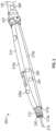
FIG. 2 is a perspective view of a smoke evacuation electrosurgical (ES) pencil of the surgical smoke evacuation system ofFIG. 1 , in accordance with the disclosure; -
FIG. 3 is a perspective, cross-sectional view of the ES pencil of the surgical smoke evacuation system ofFIG. 1 with a nozzle extender attachment according to the disclosure; -
FIGS. 4 and 5 re side, cross-sectional, schematic views of the ES pencil with a valve cover and the surgical smoke evacuation system ofFIG. 1 according to yet another aspect of the disclosure; -
FIG. 6 is a side, cross-sectional, schematic view of the surgical smoke evacuation system ofFIG. 1 with a flapper bleed valve according to another aspect of the disclosure; and -
FIGS. 7 and 8 are side, cross-sectional, schematic views of the surgical smoke evacuation system ofFIG. 1 , with the valve located at a smoke according to yet another aspect of the disclosure. - Embodiments of the disclosure are now described in detail with reference to the drawings in which like reference numerals designate identical or corresponding elements in each of the drawings. The aspects may be combined in any manner consistent with the functionality of the apparatus and/or method disclosed herein. As used herein, the term "clinician" refers to a doctor, a nurse or any other care provider and may include support personnel. Throughout this description, the term "proximal" will refer to the portion of the device or component thereof that is closer to the clinician and the term "distal" will refer to the portion of the device or component thereof that is farther from the clinician. The terms "substantially equal to" or "substantially the same" denote values that are within ±5% of each other. Additionally, in the drawings and in the description that follows, terms such as front, rear, upper, lower, top, bottom, and similar directional terms are used simply for convenience of description and are not intended to limit the disclosure. In the following description, well-known functions or constructions are not described in detail to avoid obscuring the disclosure in unnecessary detail.
- With reference to
FIG. 1 , a surgicalsmoke evacuation system 100 is shown. The surgicalsmoke evacuation system 100 generally includes asmoke evacuator 130, an ES pencil 200 (FIG. 2 ), asuction conduit 140 connecting theES pencil 200 to thesmoke evacuator 130, and one ormore valves 230a-230c configured to reduce the vacuum pressure from anozzle 212 of theES pencil 200. - The
smoke evacuator 130 includes a suction generator (e.g.,suction generator 135 inFIGS. 4-8 ) that creates negative pressure having a set vacuum force for removing smoke during a surgical operation. Thesuction conduit 140 is connected to theES pencil 200 at its distal end and to aninlet port 132 of thesmoke evacuator 130 at its proximal end. Thesuction generator 135 may include one or more fans to create the negative pressure enabling smoke removal from a surgical site. - The
valves 230a-230c are configured to reduce the vacuum pressure from anozzle 212 of theES pencil 200 when actuated in an open position. Thevalves 230a-230c may be integrated into theES pencil 200, thesuction conduit 140, and/or thesmoke evacuator 130. Thevalves 230a-230c may be in electrical communication with a pressure sensor 240 (FIG. 2 ) of theES pencil 200. - The smoke evacuator 130 also includes a
processor 190 and amemory 192. Instructions may be executed by theprocessor 190, which may include one or more digital signal processors (DSPs), general-purpose microprocessors, application-specific integrated circuits (ASICs), field programmable logic arrays (FPGAs), or other equivalent integrated or discrete logic circuitry. Accordingly, the term "processor" as used herein may refer to any of the foregoing structures or any other physical structure suitable for implementation of the described techniques. Also, the techniques could be fully implemented in one or more circuits or logic elements. It is contemplated that theprocessor 190 andmemory 192 may be located in thesmoke evacuator 130, theES pencil 200, and/or in a remote computer system. - The
memory 192 includes instructions stored thereon which, when executed by theprocessor 190, cause the surgicalsmoke evacuation system 100 to sense the vacuum pressure at thenozzle 212, by thepressure sensor 240, and actuate thevalves 230a-230c to an open position based on the sensed pressure. - In one or more examples, the described techniques may be implemented in hardware, software, firmware, or any combination thereof. If implemented in software, the functions may be stored as one or more instructions or code on a computer-readable medium and executed by a hardware-based processing unit. Computer-readable media may include non-transitory computer-readable media, which corresponds to a tangible medium such as data storage media (e.g., RAM, ROM, EEPROM, flash memory, or any other medium that can be used to store desired program code in the form of instructions or data structures and that can be accessed by a computer).
- Referring to
FIGS. 2 and3 , anES pencil 200 is disclosed, which includes ahandle housing 210 formed from a thermoplastic material. Thehandle housing 210 includes anupper portion 210a and alower portion 210b, which are secured to each other using any suitable method, e.g., ultrasonically welding, to secure internal components of theES pencil 200. Thehandle housing 10 defines alumen 210c therethrough. TheES pencil 200 also includes anozzle 212 that may be removably or securely coupled within thehousing 210 and anelectrode 214 disposed within thenozzle 212. Thenozzle 212 also defines alumen 212a, which is in fluid communication with thelumen 210c. - The
nozzle 212 is formed from a dielectric material, such as polyimide, and provides for the suctioning of gaseous byproducts through thehandle housing 210. In aspects, the dielectric material of thenozzle 212 may be a transparent, substantially transparent, or translucent material configured to facilitate visual acuity in the surgical field. However, it will be clear that an opaque or substantially opaque material may also be used as such materials would not affect the operation of the device. TheES pencil 200 also includes a connector 222 (e.g., a swivel connector) coupling thenozzle 212 to thesuction conduit 140. As shown inFIG. 3 , thenozzle 212 may also include adistal end portion 212b, which may be configured to couple to anozzle extender attachment 213. Thedistal end portion 212b may have a plurality of ribs 212c for frictionally engaging thenozzle extender attachment 213. This allows theES pencil 200 to have alonger nozzle 212 to use with alonger electrode 214 for deeper access. - The
ES pencil 200 further includes apressure sensor 240 configured to sense vacuum pressure at thenozzle 212. Thepressure sensor 240 may be a piezo sensor, a cold cathode sensor, a hot cathode sensor, a capacitive sensor, a pressure switch, and/or a Pirani vacuum pressure sensor. Thepressure sensor 240 senses the vacuum pressure that is used to draw smoke from the surgical site. - The
ES pencil 200 may further include avalve 230a disposed on or proximate to thenozzle 212. Thevalve 230a is configured to reduce the vacuum pressure from anozzle 212 when actuated in an open position. Thevalves 230a-230c may be used in conjunction with thepressure sensor 240 to dynamically control the vacuum pressure at thenozzle 212 of theES pencil 200. Thevalves 230a-230c may be bleeder valves, flap valves, and/or any suitable type of valve. In aspects, thevalves 230a-230c may have an integratedpressure sensor 240. It is contemplated that thevalve 230a-230c may be mechanically designed to open at a pre-determined pressure (e.g., by selection of spring force). - The
ES pencil 200 may further include amotion sensor 250 configured to sense the motion of theES pencil 200 and activate thesuction generator 135 based on the sensed motion.Smoke evacuators 130 may include a time limit control to prevent overuse of an air filter (not shown) configured to filter the air of smoke and other particulate matter. Generally,smoke evacuators 130, may include a timer that controls when suction is active, so the suction is not on continuously to increase the life span of the filter(s). Thesuction generator 135 and timer of thesmoke evacuator 130 may be started when theES pencil 200 is energized, i.e., in response to pressimg of an actuation pushbutton on theES pencil 200. This may create a time lag for the full vacuum to be realized at the inlet port 132 (FIG. 1 ) of thesuction conduit 140 due to typical length of thesuction conduit 140 being 10 feet or more. This time lag may cause the user to miss the initial smoke capture. - The
motion sensor 250 is in electrical communication with the processor 190 (FIG. 1 ). Themotion sensor 250 may be an accelerometer, a gyroscope, or any other suitable sensor configured to measure movement and/or tilt of theES pencil 200. Themotion sensor 250 may be disposed on a distal end of thesuction conduit 140 that turns on thesuction generator 135 when theES pencil 200 is being manipulated and a timer to turn it off when theES pencil 200 is set down. In embodiments, themotion sensor 250 may be disposed anywhere on theES pencil 200. - The
ES pencil 200 may further include atouch sensor 254 on theES pencil 200 configured to activate thesmoke evacuator 130. Thetouch sensor 254 is configured to sense contact when theES pencil 200 is grabbed by the user, indicating an intent to use theES pencil 200. Thetouch sensor 254 is located on a portion of thehousing 210 of theES pencil 200 where the surgeon normally grabs theES pencil 200 for performing surgery. Thetouch sensor 254 is also in electrical communication with theprocessor 190. By activating thesmoke evacuator 130 when theES pencil 200 is being manipulated, the surgicalsmoke evacuation system 100 can capture more smoke than activating thesmoke evacuator 130 only when theES pencil 200 is electrically active. - The
connector 222 of theES pencil 200 may further be configured for electrical communication between the pressure sensor and the suction source (e.g., smoke evacuator 130) to prevent a standard suction conduit from being used with the surgicalsmoke evacuation system 100 ofFIG. 1 . Thisconnector 222 may include amating sensor 260 configured to sense a mating connection with thesuction generator 135. Themating sensor 260 may include a unique identifier, which may be used by the processor to detect and confirm if theES pencil 200 is mated with thecorrect suction generator 135. Themating sensor 260 may include a Radio Frequency Identification (RFID) sensor configured to send and receive the unique identifier to theprocessor 190 to enable mating of theES pencil 200 with thesmoke evacuator 130. The smoke evacuator 130 may include an RFID tag (not shown) configured to be scanned by the RFID reader of themating sensor 260 of theES pencil 200. - The
connector 222 further may include a mechanical interface configured to mate with asuction conduit 140 having a counterpart mechanical interface. For example, the mechanical interface may include an outer shape such as a triangular shape, or other suitable outer shape. Thus, if the connector was the wrong outer shape, e.g., round instead of triangular, or the RFID indicated the wrong unique identifier, thesuction generator 135 of thesmoke evacuator 130 may be limited to generating a lower vacuum (e.g., below about -15 kPa). -
FIGS. 4 and 5 illustrate a side cross-sectional view of the surgicalsmoke evacuation system 100. As shown inFIGS. 4 and 5 , theES pencil 200 may further include acover 600 to prevent occlusion of thevalve 230a when thevalve 230a is in an open position. Thevalve cover 600 may be a mesh cover, or any other cover which permits the flow of air. For example, thecover 600 may include a number of (e.g., two) inlets located a distance apart such that both inlets would not be easily covered, for example, by the pad of a single finger. The cover may include raised ridges with inlet holes in troughs would allow airflow even when covered, for example by by a finger. - In an aspect, the
processor 190 may control higher vacuum pressure with thepressure sensor 240 at the nozzle 212 (FIG. 2 ) by enabling dynamic control of the vacuum pressure generated by thesuction generator 135 of thesmoke evacuator 130. If thenozzle 212 is occluded (e.g., bytissue 700 as inFIG. 5 ), then the processor 190 (FIG. 1 ) may sense a vacuum at thenozzle 212 above a threshold, which may be about -15 kPa, and may control the amount of vacuum generated by thesuction generator 135 to equalize the pressure to a maximum of about - 15 kPa at theinlet port 132 to thesmoke evacuator 130. Even though -15 kPa is used as an example threshold, other thresholds are contemplated by the disclosure. - In another example, the
suction generator 135 may generate a vacuum pressure atinlet port 132 of thesmoke evacuator 130 to be above a certain evacuator threshold, which may be about -60 kPa to compensate for pressure drop at theES pencil 200. The vacuum pressure may drop along thesuction conduit 140 and the length of theES pencil 200. This reduced vacuum pressure may be sensed by thepressure sensor 240 at thenozzle 212 at a lower value, for example, about -13 kPa. In this example, thenozzle 212 may be partially occluded (e.g., by tissue 700), causing the vacuum to increase up to about -15 kPa. The processor 190 (FIG. 1 ) receives a signal from the pressure sensor 240 (FIG. 2 ), which is located at thenozzle 212, compares the sensed vacuum pressure to the predetermined nozzle threshold (about -15 kPa), and control thesmoke evacuator 130 to reduce the vacuum pressure. -
FIG. 6 shows a side, cross-sectional view of the surgical smoke evacuation system ofFIG. 1 with thevalve 230a shown as a flapper bleed valve. In a case where thenozzle 212 is occluded (e.g., by tissue), thevalve 230a occludes the main smoke flow until the tissue (or other occlusion) is removed from thenozzle 212. Thesuction generator 135 may include active vacuum control, controlled byprocessor 190. For example, as thenozzle 212 is occluded, the pressure sensor 240 (FIG. 2 ) senses an increase in pressure above a predetermined nozzle threshold (e.g., about -15 kPa), and theprocessor 190 reduces the amount of vacuum generated by thesuction generator 135 of thesmoke evacuator 130. -
FIGS. 7 and 8 illustrate side, cross-sectional side views of the surgical smoke evacuation system ofFIG. 1 , with thevalve 230b located at asmoke evacuator 130 of the surgical smoke evacuation system ofFIG. 1 . For example,processor 190 can sense, by thepressure sensor 240, that the vacuum pressure at thenozzle 212 of theES pencil 200 is about -60 kPa (because thenozzle 212 is occluded, for example, by tissue 700). Theprocessor 190 may actuate thevalve 230b located near thesuction generator 135 to the open position to quickly reduce the vacuum from about -60 kPa to about -15 kPa. It is contemplated thatadditional pressure sensors 240 alongsuction conduit 140 and within thesmoke evacuator 130 may also be used to regulate the vacuum pressure (FIG. 7 ). - It will be understood that various modifications may be made to the aspects of the presently disclosed smoke evacuation ES pencils. Therefore, the above description should not be construed as limiting but merely as exemplifications of aspects. Those skilled in the art will envision other modifications within the scope and spirit of the disclosure.
- The invention may be described by reference to the following numbered paragraphs:-
- 1. An electrosurgical pencil comprising:
- a handle housing having a proximal end portion and a distal end portion, the handle housing defining a lumen therethrough;
- a nozzle in fluid communication with the lumen;
- a pressure sensor configured to sense a vacuum pressure at the nozzle;
- a connector coupled to the distal end portion of the handle housing, the connector configured to couple to a suction source; and
- an electrode configured to couple to a source of electrosurgical energy.
- 2. The electrosurgical pencil according to
paragraph 1, further comprising a valve configured to reduce or remove the vacuum pressure at the nozzle when actuated. - 3. The electrosurgical pencil according to paragraph 2, wherein the valve is configured to actuate to an open position in response to a pressure signal measured by the pressure sensor exceeding a preset threshold.
- 4. The electrosurgical pencil according to paragraph 3, wherein the pressure sensor is integrated into the valve.
- 5. The electrosurgical pencil according to
paragraph 1, further comprising a motion sensor disposed on the nozzle, wherein the motion sensor is configured to transmit a motion signal to the suction source to initiate suction. - 6. The electrosurgical pencil according to paragraph 2, wherein the valve includes a cover configured to prevent actuation of the valve by an external force.
- 7. The electrosurgical pencil according to
paragraph 1, wherein the connector includes a mating sensor configured to sense a mating connection with the suction source. - 8. The electrosurgical pencil according to paragraph 7, wherein the mating sensor includes a unique identifier.
- 9. The electrosurgical pencil according to
paragraph 1, wherein the connector is further configured for electrical communication between the pressure sensor and the suction source. - 10. The electrosurgical pencil according to
paragraph 1, wherein the connector includes a mechanical interface configured to mate with a suction conduit having a counterpart mechanical interface. - 11. A surgical smoke evacuation system, comprising:
- a smoke evacuator including a suction generator configured to create a vacuum pressure;
- an electrosurgical pencil including:
- a nozzle; and
- a pressure sensor configured to sense vacuum pressure at the nozzle;
- a suction conduit coupling the nozzle to the smoke evacuator;
- a valve configured to reduce the vacuum pressure from the nozzle;
- a processor; and
- a memory, including instructions stored thereon which, when executed by the processor, cause the surgical smoke evacuation system to:
- sense the vacuum pressure at the nozzle; and
- actuate the valve to an open position based on the sensed pressure.
- 12. The smoke evacuation system according to paragraph 11, wherein the valve is configured to open to reduce the vacuum pressure from the nozzle of the electrosurgical pencil in response to the sensed vacuum force being greater than a predetermined threshold.
- 13. The smoke evacuation system according to paragraph 11, further comprising a motion sensor disposed on the nozzle,
wherein the instructions, when executed by the processor, further causes the system to:- sense a signal by the motion sensor indicating movement of the electrosurgical pencil; and
- initiate suction by the smoke evacuator based on the sensed signal.
- 14. The smoke evacuation system according to paragraph 11, further comprising a motion sensor disposed on the nozzle,
wherein the instructions, when executed by the processor, further causes the system to:- sense a signal by the motion sensor indicating that the electrosurgical pencil is at a resting position; and
- stop suction by the smoke evacuator based on the sensed signal.
- 15. The smoke evacuation system according to paragraph 11, wherein the valve includes a cover configured to prevent actuation of the valve by an external force.
- 16. The smoke evacuation system according to paragraph 11, wherein the pressure sensor is integrated into the valve.
- 17. The smoke evacuation system according to paragraph 11, wherein the instructions, when executed by the processor, further cause the system to:
dynamically adjust the vacuum pressure generated by the smoke evacuator based on the sensed vacuum pressure at the nozzle. - 18. The smoke evacuation system according to paragraph 11, wherein the instructions, when executed by the processor, further cause the system to:
- determine the nozzle is occluded based on the sensed signal; and
- dynamically adjust the vacuum pressure generated by the smoke evacuator based on the determined occlusion.
- 19. The smoke evacuation system according to paragraph 18, wherein the instructions, when executed by the processor, further cause the system to:
- determine whether occlusion is removed based on the sensed signal; and
- dynamically increase the vacuum pressure generated by the smoke evacuator based on the determination the occlusion was removed.
- 20. The smoke evacuation system according to paragraph 11, wherein the electrosurgical pencil includes a connector configured to couple to a suction source, wherein the connector includes a mating sensor configured to sense a mating connection with the suction source.
Claims (15)
- An electrosurgical pencil comprising:a handle housing having a proximal end portion and a distal end portion, the handle housing defining a lumen therethrough;a nozzle in fluid communication with the lumen;a pressure sensor configured to sense a vacuum pressure at the nozzle;a connector coupled to the distal end portion of the handle housing, the connector configured to couple to a suction source; andan electrode configured to couple to a source of electrosurgical energy.
- The electrosurgical pencil according to claim 1, further comprising a valve configured to reduce or remove the vacuum pressure at the nozzle when actuated, preferably wherein the valve includes a cover configured to prevent actuation of the valve by an external force.
- The electrosurgical pencil according to claim 2, wherein the valve is configured to actuate to an open position in response to a pressure signal measured by the pressure sensor exceeding a preset threshold preferably, wherein the pressure sensor is integrated into the valve.
- The electrosurgical pencil according to any one of claims 1 to 3, further comprising a motion sensor disposed on the nozzle, wherein the motion sensor is configured to transmit a motion signal to the suction source to initiate suction.
- The electrosurgical pencil according to any preceding claim, wherein the connector includes a mating sensor configured to sense a mating connection with the suction source, preferably wherein the mating sensor includes a unique identifier.
- The electrosurgical pencil according to any preceding claim, wherein the connector is further configured for electrical communication between the pressure sensor and the suction source.
- The electrosurgical pencil according to any preceding claim, wherein the connector includes a mechanical interface configured to mate with a suction conduit having a counterpart mechanical interface.
- A surgical smoke evacuation system, comprising:a smoke evacuator including a suction generator configured to create a vacuum pressure;an electrosurgical pencil including:a nozzle; anda pressure sensor configured to sense vacuum pressure at the nozzle;a suction conduit coupling the nozzle to the smoke evacuator;a valve configured to reduce the vacuum pressure from the nozzle;a processor; anda memory, including instructions stored thereon which, when executed by the processor, cause the surgical smoke evacuation system to:sense the vacuum pressure at the nozzle; andactuate the valve to an open position based on the sensed pressure.
- The smoke evacuation system according to claim 8, wherein the valve is configured to open to reduce the vacuum pressure from the nozzle of the electrosurgical pencil in response to the sensed vacuum force being greater than a predetermined threshold.
- The smoke evacuation system according to claim 8 or 9, further comprising a motion sensor disposed on the nozzle,
wherein the instructions, when executed by the processor, further causes the system to:sense a signal by the motion sensor indicating movement of the electrosurgical pencil; andinitiate suction by the smoke evacuator based on the sensed signal. - The smoke evacuation system according to claim 8, 9 or 10 further comprising a motion sensor disposed on the nozzle,
wherein the instructions, when executed by the processor, further causes the system to:sense a signal by the motion sensor indicating that the electrosurgical pencil is at a resting position; andstop suction by the smoke evacuator based on the sensed signal. - The smoke evacuation system according to any one of claims 8 to 11, wherein the valve includes a cover configured to prevent actuation of the valve by an external force.
- The smoke evacuation system according to any one of claims 8 to 12, wherein the pressure sensor is integrated into the valve.
- The smoke evacuation system according to any one of claims 8 to 13 , wherein the instructions, when executed by the processor, further cause the system to:
dynamically adjust the vacuum pressure generated by the smoke evacuator based on the sensed vacuum pressure at the nozzle, preferably wherein the instructions, when executed by the processor, further cause the system to:determine the nozzle is occluded based on the sensed signal; anddynamically adjust the vacuum pressure generated by the smoke evacuator based on the determined occlusion further preferably wherein the instructions, when executed by the processor, further cause the system to:determine whether occlusion is removed based on the sensed signal; anddynamically increase the vacuum pressure generated by the smoke evacuator based on the determination the occlusion was removed. - The smoke evacuation system according to any one of claims 8 to 14, wherein the electrosurgical pencil includes a connector configured to couple to a suction source, wherein the connector includes a mating sensor configured to sense a mating connection with the suction source.
Applications Claiming Priority (2)
| Application Number | Priority Date | Filing Date | Title |
|---|---|---|---|
| US202163236377P | 2021-08-24 | 2021-08-24 | |
| US17/868,851 US20230067531A1 (en) | 2021-08-24 | 2022-07-20 | Active control of surgical smoke evacuation |
Publications (1)
| Publication Number | Publication Date |
|---|---|
| EP4140430A1 true EP4140430A1 (en) | 2023-03-01 |
Family
ID=83049898
Family Applications (1)
| Application Number | Title | Priority Date | Filing Date |
|---|---|---|---|
| EP22191547.3A Withdrawn EP4140430A1 (en) | 2021-08-24 | 2022-08-22 | Active control of surgical smoke evacuation |
Country Status (3)
| Country | Link |
|---|---|
| US (1) | US20230067531A1 (en) |
| EP (1) | EP4140430A1 (en) |
| CN (1) | CN115715701A (en) |
Families Citing this family (1)
| Publication number | Priority date | Publication date | Assignee | Title |
|---|---|---|---|---|
| WO2025229566A1 (en) * | 2024-05-03 | 2025-11-06 | Covidien Lp | Surgical plume evacuation systems and methods |
Citations (7)
| Publication number | Priority date | Publication date | Assignee | Title |
|---|---|---|---|---|
| US5413575A (en) * | 1994-04-19 | 1995-05-09 | Innovative Medical Technologies, Ltd. | Multifunction electrocautery tool |
| US5968032A (en) * | 1998-03-30 | 1999-10-19 | Sleister; Dennis R. | Smoke evacuator for a surgical laser or cautery plume |
| DE202010015327U1 (en) * | 2010-11-12 | 2011-01-13 | Kls Martin Gmbh + Co. Kg | Device for extracting flue gas from an operating area |
| WO2018053229A1 (en) * | 2016-09-16 | 2018-03-22 | Invuity, Inc. | Methods and apparatus for electrosurgical illumination |
| WO2019018726A1 (en) * | 2017-07-21 | 2019-01-24 | WU, Patricia, Wanping | Ancillary system having an exhaust device for surgery |
| US20190201137A1 (en) * | 2017-12-28 | 2019-07-04 | Ethicon Llc | Method of robotic hub communication, detection, and control |
| US20190201594A1 (en) * | 2017-12-28 | 2019-07-04 | Ethicon Llc | Method of sensing particulate from smoke evacuated from a patient, adjusting the pump speed based on the sensed information, and communicating the functional parameters of the system to the hub |
Family Cites Families (6)
| Publication number | Priority date | Publication date | Assignee | Title |
|---|---|---|---|---|
| US5830214A (en) * | 1994-11-08 | 1998-11-03 | Heartport, Inc. | Fluid-evacuating electrosurgical device |
| US9439677B2 (en) * | 2012-01-20 | 2016-09-13 | Iogyn, Inc. | Medical device and methods |
| AU2012388657B2 (en) * | 2012-08-28 | 2017-09-07 | Covidien Lp | Adjustable electrosurgical pencil |
| US10709490B2 (en) * | 2014-05-07 | 2020-07-14 | Medtronic Ardian Luxembourg S.A.R.L. | Catheter assemblies comprising a direct heating element for renal neuromodulation and associated systems and methods |
| US11304745B2 (en) * | 2017-12-28 | 2022-04-19 | Cilag Gmbh International | Surgical evacuation sensing and display |
| CN109480951B (en) * | 2018-12-29 | 2024-01-12 | 杭州圣石科技股份有限公司 | Disassembly-free flushable clip applier |
-
2022
- 2022-07-20 US US17/868,851 patent/US20230067531A1/en active Pending
- 2022-08-22 EP EP22191547.3A patent/EP4140430A1/en not_active Withdrawn
- 2022-08-23 CN CN202211010407.3A patent/CN115715701A/en active Pending
Patent Citations (7)
| Publication number | Priority date | Publication date | Assignee | Title |
|---|---|---|---|---|
| US5413575A (en) * | 1994-04-19 | 1995-05-09 | Innovative Medical Technologies, Ltd. | Multifunction electrocautery tool |
| US5968032A (en) * | 1998-03-30 | 1999-10-19 | Sleister; Dennis R. | Smoke evacuator for a surgical laser or cautery plume |
| DE202010015327U1 (en) * | 2010-11-12 | 2011-01-13 | Kls Martin Gmbh + Co. Kg | Device for extracting flue gas from an operating area |
| WO2018053229A1 (en) * | 2016-09-16 | 2018-03-22 | Invuity, Inc. | Methods and apparatus for electrosurgical illumination |
| WO2019018726A1 (en) * | 2017-07-21 | 2019-01-24 | WU, Patricia, Wanping | Ancillary system having an exhaust device for surgery |
| US20190201137A1 (en) * | 2017-12-28 | 2019-07-04 | Ethicon Llc | Method of robotic hub communication, detection, and control |
| US20190201594A1 (en) * | 2017-12-28 | 2019-07-04 | Ethicon Llc | Method of sensing particulate from smoke evacuated from a patient, adjusting the pump speed based on the sensed information, and communicating the functional parameters of the system to the hub |
Also Published As
| Publication number | Publication date |
|---|---|
| CN115715701A (en) | 2023-02-28 |
| US20230067531A1 (en) | 2023-03-02 |
Similar Documents
| Publication | Publication Date | Title |
|---|---|---|
| US5242442A (en) | Smoke aspirating electrosurgical device | |
| US20220257306A1 (en) | Improved electrosurgical device with vacuum port | |
| US9289261B2 (en) | Electrosurgical device with vacuum port | |
| KR101805115B1 (en) | Fixed position rf electrode | |
| CN106170262B (en) | Plasma disposal system | |
| EP1278471B1 (en) | Vibration sensitive ablation apparatus | |
| US5348555A (en) | Endoscopic suction, irrigation and cautery instrument | |
| US12059194B2 (en) | Electrosurgical device with vacuum port | |
| US20020103485A1 (en) | Electrosurgical pencil with a smoke evacuating blade | |
| US11589917B2 (en) | Electrosurgical device with vacuum port | |
| KR101073767B1 (en) | Smoke Suction Easy Electrosurgical Device | |
| CN110934637A (en) | Smoke exhausting electrosurgical pencil with adjustable electrode and ventilation tube | |
| US20080287893A1 (en) | Air suctioning and filtering device having instantly available air suctioning and thermal sensing | |
| US20230067531A1 (en) | Active control of surgical smoke evacuation | |
| US20260069351A1 (en) | Smoke evacuation instrument with illumination nozzle | |
| WO2014169135A2 (en) | Laparoscopic suction device and method | |
| AU2008203348B2 (en) | Electrosurgical device | |
| CN115697225B (en) | Surgical electrosurgical pen with blowing and suction | |
| CN216876579U (en) | Minimally invasive electrode | |
| CN221205648U (en) | An electric knife device with suction mechanism | |
| CN217338820U (en) | Flexible electrode | |
| US12433667B2 (en) | Smoke evacuation electrosurgical pencil with lighting | |
| CN216294240U (en) | Laparoscope suction apparatus with bipolar electrocoagulation function | |
| CN120456875A (en) | Integrated electrosurgical smoke evacuation system | |
| CA2488862A1 (en) | Instant-on air suctioning and filtering device |
Legal Events
| Date | Code | Title | Description |
|---|---|---|---|
| PUAI | Public reference made under article 153(3) epc to a published international application that has entered the european phase |
Free format text: ORIGINAL CODE: 0009012 |
|
| STAA | Information on the status of an ep patent application or granted ep patent |
Free format text: STATUS: REQUEST FOR EXAMINATION WAS MADE |
|
| 17P | Request for examination filed |
Effective date: 20220822 |
|
| AK | Designated contracting states |
Kind code of ref document: A1 Designated state(s): AL AT BE BG CH CY CZ DE DK EE ES FI FR GB GR HR HU IE IS IT LI LT LU LV MC MK MT NL NO PL PT RO RS SE SI SK SM TR |
|
| STAA | Information on the status of an ep patent application or granted ep patent |
Free format text: STATUS: THE APPLICATION HAS BEEN WITHDRAWN |
|
| 18W | Application withdrawn |
Effective date: 20230825 |