EP4138207A1 - Power storage element - Google Patents
Power storage element Download PDFInfo
- Publication number
- EP4138207A1 EP4138207A1 EP21803725.7A EP21803725A EP4138207A1 EP 4138207 A1 EP4138207 A1 EP 4138207A1 EP 21803725 A EP21803725 A EP 21803725A EP 4138207 A1 EP4138207 A1 EP 4138207A1
- Authority
- EP
- European Patent Office
- Prior art keywords
- case
- metal layer
- flange portion
- metal
- penetrating direction
- Prior art date
- Legal status (The legal status is an assumption and is not a legal conclusion. Google has not performed a legal analysis and makes no representation as to the accuracy of the status listed.)
- Pending
Links
Images







Classifications
-
- H—ELECTRICITY
- H01—ELECTRIC ELEMENTS
- H01M—PROCESSES OR MEANS, e.g. BATTERIES, FOR THE DIRECT CONVERSION OF CHEMICAL ENERGY INTO ELECTRICAL ENERGY
- H01M50/00—Constructional details or processes of manufacture of the non-active parts of electrochemical cells other than fuel cells, e.g. hybrid cells
- H01M50/50—Current conducting connections for cells or batteries
- H01M50/543—Terminals
- H01M50/564—Terminals characterised by their manufacturing process
-
- H—ELECTRICITY
- H01—ELECTRIC ELEMENTS
- H01G—CAPACITORS; CAPACITORS, RECTIFIERS, DETECTORS, SWITCHING DEVICES, LIGHT-SENSITIVE OR TEMPERATURE-SENSITIVE DEVICES OF THE ELECTROLYTIC TYPE
- H01G11/00—Hybrid capacitors, i.e. capacitors having different positive and negative electrodes; Electric double-layer [EDL] capacitors; Processes for the manufacture thereof or of parts thereof
- H01G11/74—Terminals, e.g. extensions of current collectors
-
- H—ELECTRICITY
- H01—ELECTRIC ELEMENTS
- H01M—PROCESSES OR MEANS, e.g. BATTERIES, FOR THE DIRECT CONVERSION OF CHEMICAL ENERGY INTO ELECTRICAL ENERGY
- H01M50/00—Constructional details or processes of manufacture of the non-active parts of electrochemical cells other than fuel cells, e.g. hybrid cells
- H01M50/10—Primary casings; Jackets or wrappings
- H01M50/102—Primary casings; Jackets or wrappings characterised by their shape or physical structure
- H01M50/103—Primary casings; Jackets or wrappings characterised by their shape or physical structure prismatic or rectangular
-
- H—ELECTRICITY
- H01—ELECTRIC ELEMENTS
- H01M—PROCESSES OR MEANS, e.g. BATTERIES, FOR THE DIRECT CONVERSION OF CHEMICAL ENERGY INTO ELECTRICAL ENERGY
- H01M50/00—Constructional details or processes of manufacture of the non-active parts of electrochemical cells other than fuel cells, e.g. hybrid cells
- H01M50/10—Primary casings; Jackets or wrappings
- H01M50/172—Arrangements of electric connectors penetrating the casing
- H01M50/174—Arrangements of electric connectors penetrating the casing adapted for the shape of the cells
- H01M50/176—Arrangements of electric connectors penetrating the casing adapted for the shape of the cells for prismatic or rectangular cells
-
- H—ELECTRICITY
- H01—ELECTRIC ELEMENTS
- H01M—PROCESSES OR MEANS, e.g. BATTERIES, FOR THE DIRECT CONVERSION OF CHEMICAL ENERGY INTO ELECTRICAL ENERGY
- H01M50/00—Constructional details or processes of manufacture of the non-active parts of electrochemical cells other than fuel cells, e.g. hybrid cells
- H01M50/50—Current conducting connections for cells or batteries
- H01M50/502—Interconnectors for connecting terminals of adjacent batteries; Interconnectors for connecting cells outside a battery casing
- H01M50/514—Methods for interconnecting adjacent batteries or cells
- H01M50/516—Methods for interconnecting adjacent batteries or cells by welding, soldering or brazing
-
- H—ELECTRICITY
- H01—ELECTRIC ELEMENTS
- H01M—PROCESSES OR MEANS, e.g. BATTERIES, FOR THE DIRECT CONVERSION OF CHEMICAL ENERGY INTO ELECTRICAL ENERGY
- H01M50/00—Constructional details or processes of manufacture of the non-active parts of electrochemical cells other than fuel cells, e.g. hybrid cells
- H01M50/50—Current conducting connections for cells or batteries
- H01M50/502—Interconnectors for connecting terminals of adjacent batteries; Interconnectors for connecting cells outside a battery casing
- H01M50/521—Interconnectors for connecting terminals of adjacent batteries; Interconnectors for connecting cells outside a battery casing characterised by the material
- H01M50/522—Inorganic material
-
- H—ELECTRICITY
- H01—ELECTRIC ELEMENTS
- H01M—PROCESSES OR MEANS, e.g. BATTERIES, FOR THE DIRECT CONVERSION OF CHEMICAL ENERGY INTO ELECTRICAL ENERGY
- H01M50/00—Constructional details or processes of manufacture of the non-active parts of electrochemical cells other than fuel cells, e.g. hybrid cells
- H01M50/50—Current conducting connections for cells or batteries
- H01M50/528—Fixed electrical connections, i.e. not intended for disconnection
-
- H—ELECTRICITY
- H01—ELECTRIC ELEMENTS
- H01M—PROCESSES OR MEANS, e.g. BATTERIES, FOR THE DIRECT CONVERSION OF CHEMICAL ENERGY INTO ELECTRICAL ENERGY
- H01M50/00—Constructional details or processes of manufacture of the non-active parts of electrochemical cells other than fuel cells, e.g. hybrid cells
- H01M50/50—Current conducting connections for cells or batteries
- H01M50/531—Electrode connections inside a battery casing
-
- H—ELECTRICITY
- H01—ELECTRIC ELEMENTS
- H01M—PROCESSES OR MEANS, e.g. BATTERIES, FOR THE DIRECT CONVERSION OF CHEMICAL ENERGY INTO ELECTRICAL ENERGY
- H01M50/00—Constructional details or processes of manufacture of the non-active parts of electrochemical cells other than fuel cells, e.g. hybrid cells
- H01M50/50—Current conducting connections for cells or batteries
- H01M50/543—Terminals
- H01M50/547—Terminals characterised by the disposition of the terminals on the cells
- H01M50/55—Terminals characterised by the disposition of the terminals on the cells on the same side of the cell
-
- H—ELECTRICITY
- H01—ELECTRIC ELEMENTS
- H01M—PROCESSES OR MEANS, e.g. BATTERIES, FOR THE DIRECT CONVERSION OF CHEMICAL ENERGY INTO ELECTRICAL ENERGY
- H01M50/00—Constructional details or processes of manufacture of the non-active parts of electrochemical cells other than fuel cells, e.g. hybrid cells
- H01M50/50—Current conducting connections for cells or batteries
- H01M50/543—Terminals
- H01M50/552—Terminals characterised by their shape
- H01M50/553—Terminals adapted for prismatic, pouch or rectangular cells
-
- H—ELECTRICITY
- H01—ELECTRIC ELEMENTS
- H01M—PROCESSES OR MEANS, e.g. BATTERIES, FOR THE DIRECT CONVERSION OF CHEMICAL ENERGY INTO ELECTRICAL ENERGY
- H01M50/00—Constructional details or processes of manufacture of the non-active parts of electrochemical cells other than fuel cells, e.g. hybrid cells
- H01M50/50—Current conducting connections for cells or batteries
- H01M50/543—Terminals
- H01M50/552—Terminals characterised by their shape
- H01M50/553—Terminals adapted for prismatic, pouch or rectangular cells
- H01M50/557—Plate-shaped terminals
-
- H—ELECTRICITY
- H01—ELECTRIC ELEMENTS
- H01M—PROCESSES OR MEANS, e.g. BATTERIES, FOR THE DIRECT CONVERSION OF CHEMICAL ENERGY INTO ELECTRICAL ENERGY
- H01M50/00—Constructional details or processes of manufacture of the non-active parts of electrochemical cells other than fuel cells, e.g. hybrid cells
- H01M50/50—Current conducting connections for cells or batteries
- H01M50/543—Terminals
- H01M50/562—Terminals characterised by the material
-
- H—ELECTRICITY
- H01—ELECTRIC ELEMENTS
- H01M—PROCESSES OR MEANS, e.g. BATTERIES, FOR THE DIRECT CONVERSION OF CHEMICAL ENERGY INTO ELECTRICAL ENERGY
- H01M50/00—Constructional details or processes of manufacture of the non-active parts of electrochemical cells other than fuel cells, e.g. hybrid cells
- H01M50/50—Current conducting connections for cells or batteries
- H01M50/543—Terminals
- H01M50/564—Terminals characterised by their manufacturing process
- H01M50/566—Terminals characterised by their manufacturing process by welding, soldering or brazing
-
- H—ELECTRICITY
- H01—ELECTRIC ELEMENTS
- H01M—PROCESSES OR MEANS, e.g. BATTERIES, FOR THE DIRECT CONVERSION OF CHEMICAL ENERGY INTO ELECTRICAL ENERGY
- H01M50/00—Constructional details or processes of manufacture of the non-active parts of electrochemical cells other than fuel cells, e.g. hybrid cells
- H01M50/50—Current conducting connections for cells or batteries
- H01M50/543—Terminals
- H01M50/564—Terminals characterised by their manufacturing process
- H01M50/567—Terminals characterised by their manufacturing process by fixing means, e.g. screws, rivets or bolts
-
- Y—GENERAL TAGGING OF NEW TECHNOLOGICAL DEVELOPMENTS; GENERAL TAGGING OF CROSS-SECTIONAL TECHNOLOGIES SPANNING OVER SEVERAL SECTIONS OF THE IPC; TECHNICAL SUBJECTS COVERED BY FORMER USPC CROSS-REFERENCE ART COLLECTIONS [XRACs] AND DIGESTS
- Y02—TECHNOLOGIES OR APPLICATIONS FOR MITIGATION OR ADAPTATION AGAINST CLIMATE CHANGE
- Y02E—REDUCTION OF GREENHOUSE GAS [GHG] EMISSIONS, RELATED TO ENERGY GENERATION, TRANSMISSION OR DISTRIBUTION
- Y02E60/00—Enabling technologies; Technologies with a potential or indirect contribution to GHG emissions mitigation
- Y02E60/10—Energy storage using batteries
Definitions
- Patent Document 1 JP-A-2009-259524
- An energy storage device includes: an electrode assembly; a case that houses the electrode assembly; and a metal external terminal disposed in the case, wherein the external terminal includes a flange portion spreading along the case outside the case; and a shaft portion extending from the flange portion, penetrating the case, and conductively connected to the electrode assembly, the flange portion is formed of a clad material including a plurality of metal layers stacked in a penetrating direction of the shaft portion, and includes a through hole through which the shaft portion is inserted, the shaft portion includes an enlarged diameter portion spreading along a surface of the flange portion on a case side, and a swaged portion that spreads along a surface of the flange portion on a side opposite to the case and sandwiches a peripheral edge portion of the through hole in the flange portion between the swaged portion and the enlarged diameter portion, and a first metal layer that is a metal layer at an end opposite to the case in the penetrating direction among the plurality
- the electrical resistance between the second metal layer and the enlarged diameter portion is suppressed, whereby conductivity between the shaft portion and the flange portion is improved.
- the energy storage device of the present embodiment is a nonaqueous electrolyte secondary battery. More specifically, the energy storage device is a lithium ion secondary battery utilizing electron transfer occurring with the movement of lithium ions. This type of energy storage device supplies electric energy. A single or a plurality of energy storage devices are used. Specifically, when the required output and the required voltage are small, the energy storage device is used alone. On the other hand, when at least one of the required output and the required voltage is large, the energy storage device is used for an energy storage apparatus in combination with another energy storage device. In the energy storage apparatus, the energy storage device used for the energy storage apparatus supplies electric energy.
- the electrode assembly 2 includes wound electrodes (a positive electrode 23 and a negative electrode 24).
- the electrode assembly 2 includes a winding core 21 and a layered product 22 formed of an electrode wound around the winding core 21.
- the positive electrode 23 and the negative electrode 24 are stacked in a state of being insulated from each other.
- lithium ions move between the positive electrode 23 and the negative electrode 24, whereby the energy storage device 1 is charged and discharged.
- the uncovered stacked portion 26 is provided at each electrode of the electrode assembly 2. That is, the uncovered stacked portion 26 in which only the uncovered portion of the positive electrode 23 is stacked forms an uncovered stacked portion of the positive electrode in the electrode assembly 2, and the uncovered stacked portion 26 in which only the uncovered portion of the negative electrode 24 is stacked forms an uncovered stacked portion of the negative electrode in the electrode assembly 2.
- the electrolyte solution is a nonaqueous electrolyte solution.
- the electrolyte solution is obtained by dissolving an electrolyte salt in an organic solvent.
- organic solvents include cyclic carbonates, such as propylene carbonate and ethylene carbonate, and linear carbonates, such as dimethyl carbonate, diethyl carbonate, and ethyl methyl carbonate.
- the electrolyte salt is LiClO 4 , LiBF 4 , LiPF 6 or the like.
- the external terminal 4 is a portion of the energy storage device 1 which is electrically connected to an external terminal of another energy storage device, an external device, or the like.
- the external terminal 4 is formed of a conductive member.
- the energy storage device 1 of the present embodiment includes two types of the external terminals 4 that are a positive electrode terminal 4A and a negative electrode terminal 4B. These two external terminals 4 are arranged in the case 3 at positions spaced in the X axis direction, more specifically, at each end portion position of the case 3 in the X axis direction in a state where portions 42A and 42B thereof penetrate the case 3.
- insulating members 7A and 7B are arranged between the external terminal 4 and the case 3 and between the case 3 and the current collector 5.
- the insulating member 7A insulates the external terminal 4 from the case 3 (in the example of the present embodiment, the lid plate 32), and seals between the portions 42A and 42B of the external terminal 4, which penetrate the case 3, and the case 3.
- the insulating member 7B insulates the case 3 (in the example of the present embodiment, the lid plate 32) from the current collector 5.
- the positive electrode shaft portion 42A extends in the Z axis direction and penetrates the case 3. That is, the positive electrode shaft portion 42A penetrates the case 3 (lid plate 32) in the Z axis direction.
- the positive electrode shaft portion 42A includes a positive electrode shaft portion body 420A extending in the Z axis direction, and a positive electrode enlarged diameter portion 421A spreading from the positive electrode shaft portion body 420A when viewed from the Z axis direction.
- the negative electrode flange portion 41B of the present embodiment includes two metal layers which are the second metal layer 411a and the first metal layer 411b.
- the first metal layer 411b covers the peripheral end surface 411c of the remaining metal layer (second metal layer) 411a.
- the electrical resistance of the metal forming the first metal layer 411b is larger than the electrical resistance of the metal forming the second metal layer 411a.
- the second metal layer 411a is formed of copper or a copper-based metal such as a copper alloy
- the first metal layer 411b is formed of aluminum or an aluminum-based metal such as an aluminum alloy.
- the thin-walled portion 4111 is thinner than the thick-walled portion 4112 in the first metal layer 411b.
- the width of the thin-walled portion 4111 at each position in the circumferential direction is constant. That is, when viewed from the Z axis direction, a peripheral edge (boundary position with the thick-walled portion 4112) 4111a (see Fig. 7 ) of the thin-walled portion 4111 and an inner peripheral edge (boundary position with the through hole 412B) 4111b (see Fig. 7 ) are concentric circles.
- the peripheral edge 4111a of the present embodiment has a diameter of 7.3 mm
- the inner peripheral edge 4111b has a diameter of 4 mm.
Landscapes
- Chemical & Material Sciences (AREA)
- Chemical Kinetics & Catalysis (AREA)
- Electrochemistry (AREA)
- General Chemical & Material Sciences (AREA)
- Engineering & Computer Science (AREA)
- Manufacturing & Machinery (AREA)
- Power Engineering (AREA)
- Microelectronics & Electronic Packaging (AREA)
- Inorganic Chemistry (AREA)
- Connection Of Batteries Or Terminals (AREA)
- Electric Double-Layer Capacitors Or The Like (AREA)
Abstract
Description
- The present invention relates to an energy storage device including an external terminal.
- Conventionally, a lithium ion secondary battery including an external terminal constituted by a plurality of members has been known (see Patent Document 1). In this lithium ion secondary battery, as shown in
Fig. 12 , in anexternal terminal 100, ashaft portion 101 and aflange portion 102 which spreads from theshaft portion 101 and to which another member such as a bus bar is welded are formed of different members. Theshaft portion 101 and theflange portion 102 are connected by swaging. - In the
external terminal 100 in which theshaft portion 101 and theflange portion 102 are formed of different members, a clad material in which a plurality of metal layers are stacked on theflange portion 102 may be used depending on a material of a member such as a bus bar welded to theflange portion 102. - In the
external terminal 100, an end portion of theshaft portion 101 is inserted through a through hole provided in theflange portion 102, and the inserted end portion is swaged and spreads along theflange portion 102, whereby theflange portion 102 and theshaft portion 101 are connected. At the time of this swaging, a hole peripheral edge portion of a metal layer constituting a surface (surface opposite to the case side) of theflange portion 102 is compressed and tends to extend in a direction away from the through hole; however, since the metal layer is secured to the adjacent metal layer, the compressed portion cannot extend, so that when the end portion of theshaft portion 101 is swaged and spreads, a periphery of the swaged portion swells. - When such swelling occurs on the surface of the
flange portion 102, it may be difficult to connect other members due to the swelling when a member such as a bus bar is connected. - Patent Document 1:
JP-A-2009-259524 - In view of the above, an object of the present embodiment is to provide an energy storage device in which other members are easily connected to a flange portion of an external terminal even when swelling caused by swaging occurs around a swaged portion in the flange portion.
- An energy storage device according to the present embodiment includes: an electrode assembly; a case that houses the electrode assembly; and a metal external terminal disposed in the case, wherein the external terminal includes a flange portion spreading along the case outside the case; and a shaft portion extending from the flange portion, penetrating the case, and conductively connected to the electrode assembly, the flange portion is formed of a clad material including a plurality of metal layers stacked in a penetrating direction of the shaft portion, and includes a through hole through which the shaft portion is inserted, the shaft portion includes an enlarged diameter portion spreading along a surface of the flange portion on a case side, and a swaged portion that spreads along a surface of the flange portion on a side opposite to the case and sandwiches a peripheral edge portion of the through hole in the flange portion between the swaged portion and the enlarged diameter portion, and a first metal layer that is a metal layer at an end opposite to the case in the penetrating direction among the plurality of metal layers includes a concave part recessed in the penetrating direction or a through hole penetrating in the penetrating direction in a region that is larger than the swaged portion when viewed from the penetrating direction and includes the swaged portion when viewed from the penetrating direction.
-
-
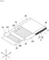
Fig. 1 is a perspective view of an energy storage device according to the present embodiment. -
Fig. 2 is an exploded perspective view of the energy storage device. -
Fig. 3 is a view for explaining a configuration of an electrode assembly provided in the energy storage device. -
Fig. 4 is an enlarged cross-sectional view of a positive electrode terminal of the energy storage device and its periphery. -
Fig. 5 is an enlarged view of a portion indicated by V inFig. 1 . -
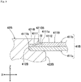
Fig. 6 is a cross-sectional view taken along line VI-VI inFig. 5 . -
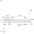
Fig. 7 is a cross-sectional view for explaining a configuration of a negative electrode flange portion. -
Fig. 8 is a cross-sectional view showing a configuration of a negative electrode shaft portion and its periphery in a state where the negative electrode shaft portion is not swaged. -
Fig. 9 is a view for explaining swelling of a thin-walled portion caused by swaging. -
Fig. 10 is an enlarged cross-sectional view for explaining a configuration of a negative electrode flange portion according to another embodiment. -
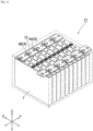
Fig. 11 is a schematic view of an energy storage apparatus including the energy storage device. -
Fig. 12 is an enlarged cross-sectional view for explaining a configuration of a conventional external terminal. - An energy storage device according to the present embodiment includes an electrode assembly, a case that houses the electrode assembly, and a metal external terminal disposed in the case, wherein the external terminal includes a flange portion spreading along the case outside the case, and a shaft portion extending from the flange portion, penetrating the case, and conductively connected to the electrode assembly, the flange portion is formed of a clad material including a plurality of metal layers stacked in a penetrating direction of the shaft portion, and includes a through hole through which the shaft portion is inserted, the shaft portion includes an enlarged diameter portion spreading along a surface of the flange portion on a case side, and a swaged portion that spreads along a surface of the flange portion on a side opposite to the case and sandwiches a peripheral edge portion of the through hole in the flange portion between the swaged portion and the enlarged diameter portion, and a first metal layer that is a metal layer at an end opposite to the case in the penetrating direction among the plurality of metal layers includes a concave part recessed in the penetrating direction or a through hole penetrating in the penetrating direction in a region that is larger than the swaged portion when viewed from the penetrating direction and includes the swaged portion when viewed from the penetrating direction.
- According to such a configuration, even if a convex part caused by swaging is formed around the swaged portion on the surface of the flange portion on the side opposite to the case, since a position of the swaged portion on the surface of the flange portion and its periphery are recessed, when another member is connected to the flange portion, the convex part does not interfere, and the connection is easy.
- In the energy storage device, the flange portion may include two metal layers that are the first metal layer and a second metal layer that is a metal layer at an end on the case side in the penetrating direction among the plurality of metal layers, and electrical resistance of a metal forming the second metal layer may be smaller than electrical resistance of a metal forming the first metal layer.
- According to such a configuration, as compared with a case where the first metal layer has a uniform thickness, the electrical resistance between the second metal layer and the enlarged diameter portion is suppressed, whereby conductivity between the shaft portion and the flange portion is improved.
- An energy storage device according to the present embodiment includes an electrode assembly, a case that houses the electrode assembly, and a metal external terminal disposed in the case, wherein the external terminal includes a flange portion spreading along an outer surface of the case outside the case, and a shaft portion extending from the flange portion, penetrating the case, and conductively connected to the electrode assembly, the flange portion is formed of a clad material including a plurality of metal layers stacked in a penetrating direction of the shaft portion, and includes a through hole through which the shaft portion is inserted, the shaft portion includes an enlarged diameter portion that is formed between the flange portion and the outer surface of the case and spreads along the outer surface of the case, and a swaged portion that spreads along a surface of the flange portion on a side opposite to the case and sandwiches a peripheral edge portion of the through hole in the flange portion between the swaged portion and the enlarged diameter portion, and a first metal layer that is a metal layer opposite to the case in the penetrating direction among the plurality of metal layers includes a concave part recessed in the penetrating direction or a through hole penetrating in the penetrating direction in a region that is larger than the swaged portion when viewed from the penetrating direction and includes the swaged portion when viewed from the penetrating direction.
- According to such a configuration, even if a convex part caused by swaging is formed around the swaged portion on the surface of the flange portion on the side opposite to the case, since a position of the swaged portion on the surface of the flange portion and its periphery are recessed, when another member is connected to the flange portion, the convex part does not interfere, and the connection is easy.
- The flange portion may include two metal layers that are the first metal layer and a second metal layer which is a metal layer facing the case in the penetrating direction among the plurality of metal layers, and electrical resistance of a metal forming the second metal layer may be smaller than electrical resistance of a metal forming the first metal layer.
- According to such a configuration, as compared with a case where the first metal layer has a uniform thickness, the electrical resistance between the second metal layer and the enlarged diameter portion is suppressed, whereby conductivity between the shaft portion and the flange portion is improved.
- The flange portion may include a convex part protruding in the penetrating direction in the concave part of the first metal layer, and the convex part may be disposed between a peripheral edge of the concave part and a peripheral edge of the swaged portion in a direction orthogonal to the penetrating direction.
- According to such a configuration, another member is easily connected to the flange portion.
- The first metal layer may have the through hole, the flange portion may include a convex part protruding in the penetrating direction, and the convex part may be disposed between a peripheral edge of the through hole and a peripheral edge of the swaged portion in a direction orthogonal to the penetrating direction.
- According to such a configuration, another member is easily connected to the flange portion.
- The second metal layer may include a peripheral end surface that is an end surface in the direction orthogonal to the penetrating direction, and the first metal layer may include a cover portion protruding in the penetrating direction, the cover portion protruding along the peripheral end surface of the second metal layer.
- The external terminal may be a negative electrode, the first metal layer may contain aluminum or an aluminum-based metal, and the second metal layer may contain copper or a copper-based metal.
- As described above, according to the present embodiment, it is possible to provide the energy storage device in which other members are easily connected to the flange portion of the external terminal even when swelling caused by swaging occurs around the swaged portion in the flange portion.
- Hereinafter, an embodiment of the present invention will be described with reference to
Figs. 1 to 9 . Names of constituent members (constituent elements) according to the present embodiment are effective in the present embodiment, and can be different from names of constituent members (constituent elements) according to the background art. - The energy storage device of the present embodiment is a nonaqueous electrolyte secondary battery. More specifically, the energy storage device is a lithium ion secondary battery utilizing electron transfer occurring with the movement of lithium ions. This type of energy storage device supplies electric energy. A single or a plurality of energy storage devices are used. Specifically, when the required output and the required voltage are small, the energy storage device is used alone. On the other hand, when at least one of the required output and the required voltage is large, the energy storage device is used for an energy storage apparatus in combination with another energy storage device. In the energy storage apparatus, the energy storage device used for the energy storage apparatus supplies electric energy.
- As shown in
Figs. 1 and2 , the energy storage device includes anelectrode assembly 2, acase 3 that houses theelectrode assembly 2, and a metalexternal terminal 4 disposed in thecase 3. Theenergy storage device 1 also includes acurrent collector 5 conductively connecting theelectrode assembly 2 and theexternal terminal 4, aninsulating member 6 disposed between theelectrode assembly 2 and thecase 3, and the like. The external terminal 4 (to be more specific, a negativeelectrode shaft portion 42B of anegative electrode terminal 4B) shown inFig. 2 has a shape before being swaged. - As also shown in
Fig. 3 , theelectrode assembly 2 includes wound electrodes (apositive electrode 23 and a negative electrode 24). Specifically, theelectrode assembly 2 includes a windingcore 21 and alayered product 22 formed of an electrode wound around the windingcore 21. In thelayered product 22, thepositive electrode 23 and thenegative electrode 24 are stacked in a state of being insulated from each other. In theelectrode assembly 2, lithium ions move between thepositive electrode 23 and thenegative electrode 24, whereby theenergy storage device 1 is charged and discharged. - The
positive electrode 23 includes a strip-shaped metal foil 231 and a positiveactive material layer 232 that is overlaid on themetal foil 231. The positiveactive material layer 232 is overlaid on themetal foil 231 in a state where one end edge portion (uncovered portion) of themetal foil 231 in a width direction is exposed. Themetal foil 231 of the present embodiment is, for example, an aluminum foil. - The
negative electrode 24 includes a strip-shaped metal foil 241 and a negativeactive material layer 242 that is overlaid on themetal foil 241. The negativeactive material layer 242 is overlaid on themetal foil 241 in a state where the other (the side opposite to the uncovered portion of themetal foil 231 of the positive electrode 23) end edge portion (uncovered portion) of themetal foil 241 in the width direction is exposed. Themetal foil 241 of the present embodiment is, for example, a copper foil. - In the
electrode assembly 2 of the present embodiment, thepositive electrode 23 and thenegative electrode 24 are wound in a state of being insulated from each other by theseparator 25. That is, in the layeredproduct 22 of the present embodiment, thepositive electrode 23, thenegative electrode 24, and theseparator 25 are stacked. - The
separator 25 is an insulating member and is disposed between thepositive electrode 23 and thenegative electrode 24. Thereby, in the electrode assembly 2 (specifically, the layered product 22), thepositive electrode 23 and thenegative electrode 24 are insulated from each other. Theseparator 25 holds an electrolyte solution in thecase 3. Thus, during charge and discharge of theenergy storage device 1, lithium ions can move between thepositive electrode 23 and thenegative electrode 24 alternately stacked with theseparator 25 interposed between the electrodes. - The
separator 25 has a strip shape, and is formed of, for example, a porous film of polyethylene, polypropylene, cellulose, polyamide, or the like. Theseparator 25 of the present embodiment includes a substrate formed of a porous film and an inorganic layer provided on the substrate. The inorganic layer contains inorganic particles such as SiO2 particles, Al2O3 particles, and boehmite (alumina hydrate). The substrate is formed of, for example, polyethylene. - The dimension of the
separator 25 in the width direction is larger than the width of the negativeactive material layer 242. Theseparator 25 is disposed between thepositive electrode 23 and thenegative electrode 24, which are stacked and staggered in the width direction in such a manner that the positiveactive material layer 232 and the negativeactive material layer 242 overlap each other in a thickness direction (stacking direction). At this time, the uncovered portion of thepositive electrode 23 and the uncovered portion of thenegative electrode 24 do not overlap each other. That is, the uncovered portion of thepositive electrode 23 protrudes in the width direction (direction orthogonal to the stacking direction) from the region where thepositive electrode 23 and thenegative electrode 24 overlap each other, and the uncovered portion of thenegative electrode 24 protrudes in the width direction (direction opposite to a protruding direction of the uncovered portion of the positive electrode 23) from the region where thepositive electrode 23 and thenegative electrode 24 overlap each other. Theelectrode assembly 2 is formed by winding thepositive electrode 23, thenegative electrode 24, and theseparator 25 around the windingcore 21 so as to obtain such a stacked state (relative position). In theelectrode assembly 2 of the present embodiment, the uncoveredstacked portion 26 of theelectrode assembly 2 is formed of a portion where only the uncovered portion of thepositive electrode 23 or the uncovered portion of thenegative electrode 24 is stacked. - The uncovered
stacked portion 26 is provided at each electrode of theelectrode assembly 2. That is, the uncoveredstacked portion 26 in which only the uncovered portion of thepositive electrode 23 is stacked forms an uncovered stacked portion of the positive electrode in theelectrode assembly 2, and the uncoveredstacked portion 26 in which only the uncovered portion of thenegative electrode 24 is stacked forms an uncovered stacked portion of the negative electrode in theelectrode assembly 2. - The
case 3 houses an electrolyte solution together with theelectrode assembly 2. Specifically, thecase 3 includes acase body 31 having an opening, and alid plate 32 blocking (closing) the opening of thecase body 31. Thecase 3 is formed of a metal having resistance to the electrolyte solution. Thecase 3 of the present embodiment is formed of, for example, aluminum or an aluminum-based metal such as an aluminum alloy. - The electrolyte solution is a nonaqueous electrolyte solution. The electrolyte solution is obtained by dissolving an electrolyte salt in an organic solvent. Examples of organic solvents include cyclic carbonates, such as propylene carbonate and ethylene carbonate, and linear carbonates, such as dimethyl carbonate, diethyl carbonate, and ethyl methyl carbonate. The electrolyte salt is LiClO4, LiBF4, LiPF6 or the like. The electrolyte solution of the present embodiment is obtained by dissolving 1 mol/L of LiPF6 in a mixed solvent prepared by mixing ethylene carbonate, dimethyl carbonate, and ethyl methyl carbonate at a ratio of ethylene carbonate : dimethyl carbonate : ethyl methyl carbonate = 3 : 2 : 5.
- The
case body 31 includes a plate-shapedblocking portion 311 and a cylindrical body portion (peripheral wall) 312 connected to a peripheral edge of the blockingportion 311. - The blocking
portion 311 is a portion located at a lower end of thecase body 31 when thecase body 31 is disposed in a posture in which the opening faces upward (that is, the portion serves as a bottom wall of thecase body 31 when the opening faces upward). The blockingportion 311 has a rectangular shape when viewed from a normal direction of the blockingportion 311. Hereinafter, a long side direction of the blockingportion 311 is defined as an X axis of an orthogonal coordinate system, a short side direction of the blockingportion 311 is defined as a Y axis of the orthogonal coordinate system, and the normal direction of the blockingportion 311 is defined as a Z axis of the orthogonal coordinate system. - The
body portion 312 has a rectangular tube shape, more specifically, a flat rectangular tube shape. Thebody portion 312 includes a pair oflong wall portions 313 extending from the long side at the peripheral edge of the blockingportion 311 and a pair ofshort wall portions 314 extending from the short side at the peripheral edge of the blockingportion 311. That is, the pair oflong wall portions 313 face each other with an interval (specifically, an interval corresponding to the short side at the peripheral edge of the blocking portion 311) in the Y axis direction, and the pair ofshort wall portions 314 face each other with an interval (specifically, an interval corresponding to the long side at the peripheral edge of the blocking portion 311) in the X axis direction. Theshort wall portions 314 connect corresponding (specifically, facing in the Y axis direction) end portions of the pair oflong wall portions 313 to each other, thereby forming thebody portion 312 having a rectangular tube shape. - As described above, the
case body 31 has a rectangular tube shape (that is, a bottomed rectangular tube shape) in which one end portion in an opening direction (Z axis direction) is closed. Theelectrode assembly 2 is housed in thecase body 31 in a state where a winding center axis C direction is directed to the X axis direction. - The
lid plate 32 is a plate-shaped member that closes the opening of thecase body 31. Thelid plate 32 of the present embodiment is a rectangular plate member that is long in the X axis direction as viewed in the Z axis direction. In thelid plate 32, a peripheral edge portion of thelid plate 32 is overlaid on an openingperipheral edge portion 34 of thecase body 31 so as to close the opening of thecase body 31. In the state where thelid plate 32 is overlaid on the openingperipheral edge portion 34, a boundary portion between thelid plate 32 and thecase body 31 is welded, whereby thecase 3 is formed. - The
external terminal 4 is a portion of theenergy storage device 1 which is electrically connected to an external terminal of another energy storage device, an external device, or the like. Theexternal terminal 4 is formed of a conductive member. Theenergy storage device 1 of the present embodiment includes two types of theexternal terminals 4 that are apositive electrode terminal 4A and anegative electrode terminal 4B. These twoexternal terminals 4 are arranged in thecase 3 at positions spaced in the X axis direction, more specifically, at each end portion position of thecase 3 in the X axis direction in a state whereportions case 3. - In the
energy storage device 1 of the present embodiment, insulatingmembers external terminal 4 and thecase 3 and between thecase 3 and thecurrent collector 5. The insulatingmember 7A insulates theexternal terminal 4 from the case 3 (in the example of the present embodiment, the lid plate 32), and seals between theportions external terminal 4, which penetrate thecase 3, and thecase 3. The insulatingmember 7B insulates the case 3 (in the example of the present embodiment, the lid plate 32) from thecurrent collector 5. - As also shown in
Fig. 4 , thepositive electrode terminal 4A includes a positiveelectrode flange portion 41A that spreads along thecase 3 outside thecase 3, and a positiveelectrode shaft portion 42A that extends from the positiveelectrode flange portion 41A, penetrates thecase 3, and is conductively connected to theelectrode assembly 2. In thepositive electrode terminal 4A, the positiveelectrode flange portion 41A and the positiveelectrode shaft portion 42A are integrated. Thepositive electrode terminal 4A of the present embodiment is formed of, for example, aluminum or an aluminum-based metal such as an aluminum alloy. - The positive
electrode flange portion 41A spreads along thelid plate 32 of thecase 3. To be more specific, the positiveelectrode flange portion 41A has a rectangular plate shape elongated in the X axis direction. The positiveelectrode flange portion 41A includes awelding surface 411A on a side opposite to thecase 3. Thewelding surface 411A faces outside in the Z axis direction (the side opposite to the case 3), and is a surface to which a member (conductive member such as a bus bar) for conductively connecting thepositive electrode terminal 4A to an external terminal of another energy storage device, an external device, and the like is welded. - The positive
electrode shaft portion 42A extends in the Z axis direction and penetrates thecase 3. That is, the positiveelectrode shaft portion 42A penetrates the case 3 (lid plate 32) in the Z axis direction. Specifically, the positiveelectrode shaft portion 42A includes a positive electrodeshaft portion body 420A extending in the Z axis direction, and a positive electrodeenlarged diameter portion 421A spreading from the positive electrodeshaft portion body 420A when viewed from the Z axis direction. - The positive electrode
shaft portion body 420A is a columnar portion extending in the Z axis direction, and penetrates the case 3 (specifically, the lid plate 32). The positive electrode shaft portion body 420 of the present embodiment has a circular columnar shape, and penetrates the insulatingmember 7A, thelid plate 32, the insulatingmember 7B, and thecurrent collector 5. - The
case 3 and thecurrent collector 5 are sandwiched between the positive electrodeenlarged diameter portion 421A and the positiveelectrode flange portion 41A in the Z axis direction. The positive electrodeenlarged diameter portion 421A of the present embodiment sandwiches the insulatingmember 7A, thelid plate 32, the insulatingmember 7B, and thecurrent collector 5 with the positiveelectrode flange portion 41A. The positive electrodeenlarged diameter portion 421A spreads (is enlarged in diameter) along thecurrent collector 5 inside thecase 3. - As shown in
Fig. 1 ,Fig. 2 , andFig. 5 toFig. 7 , thenegative electrode terminal 4B includes a negative electrode flange portion (flange portion) 41B that spreads along thecase 3 outside thecase 3, and a negative electrode shaft portion (shaft portion) 42B that extends from the negativeelectrode flange portion 41B, penetrates thecase 3, and is conductively connected to theelectrode assembly 2. In thenegative electrode terminal 4B, the negativeelectrode flange portion 41B and the negativeelectrode shaft portion 42B are separate bodies (separate members). - The negative
electrode flange portion 41B spreads along thelid plate 32 of thecase 3. To be more specific, the negativeelectrode flange portion 41B has a rectangular plate shape elongated in the X axis direction. The negativeelectrode flange portion 41B includes a throughhole 412B through which the negativeelectrode shaft portion 42B is inserted. The throughhole 412B penetrates the negativeelectrode flange portion 41B in the Z axis direction (in other words, the thickness direction of the negativeelectrode flange portion 41B). The throughhole 412B of the present embodiment has a circular shape and is disposed at a central portion of the negativeelectrode flange portion 41B. - The negative
electrode flange portion 41B includes awelding surface 411B on a side opposite to thecase 3. As with thewelding surface 411A of thepositive electrode terminal 4A, thewelding surface 411B is directed outward in the Z axis direction, and is a surface to which a conductive member such as a bus bar is welded. - The negative
electrode flange portion 41B is formed of a clad material including a plurality of (two in the example of the present embodiment)metal layers 411 stacked in the Z axis direction. The metal layers 411 adjacent to each other in the plurality ofmetal layers 411 are formed of different kinds of metals. - In the negative
electrode flange portion 41B, a metal layer (second metal layer) 411a at one end (lower side inFigs. 6 and7 ) of the plurality ofmetal layers 411 in the Z axis direction is formed of the same type of metal as the negativeelectrode shaft portion 42B. In the negativeelectrode flange portion 41B, a metal layer (first metal layer) 411b at the other end (upper side inFigs. 6 and7 ) in the Z axis direction of the plurality ofmetal layers 411 in the Z axis direction is formed of a metal different from the negativeelectrode shaft portion 42B. In the negativeelectrode flange portion 41B, thesecond metal layer 411a or thefirst metal layer 411b covers aperipheral end surface 411c of the remaining metal layer of the plurality of metal layers 411. - The negative
electrode flange portion 41B of the present embodiment includes two metal layers which are thesecond metal layer 411a and thefirst metal layer 411b. In the negativeelectrode flange portion 41B, thefirst metal layer 411b covers theperipheral end surface 411c of the remaining metal layer (second metal layer) 411a. The electrical resistance of the metal forming thefirst metal layer 411b is larger than the electrical resistance of the metal forming thesecond metal layer 411a. In the negativeelectrode flange portion 41B of the present embodiment, for example, thesecond metal layer 411a is formed of copper or a copper-based metal such as a copper alloy, and thefirst metal layer 411b is formed of aluminum or an aluminum-based metal such as an aluminum alloy. - The
second metal layer 411a is located on thecase 3 side with respect to thefirst metal layer 411b in the negativeelectrode flange portion 41B. Thesecond metal layer 411a spreads along an X-Y plane (plane including the X axis direction and the Y axis direction) direction, and the dimension (thickness) in the Z axis direction at each position in an X-Y plane direction excluding the throughhole 412B is constant. Thesecond metal layer 411a of the present embodiment has a rectangular shape having a dimension in the X axis direction of 20 mm and a dimension in the Y axis direction of 8.3 mm, and has a thickness of 0.5 mm. - The
first metal layer 411b is located on the side opposite to thecase 3 with respect to thesecond metal layer 411a in the negativeelectrode flange portion 41B. Thefirst metal layer 411b spreads along the X-Y plane (plane including the X axis direction and the Y axis direction) direction and includes a thin-walled portion (concave part) 4111 recessed in the Z axis direction or a through hole penetrating in the Z axis direction. Thefirst metal layer 411b of the present embodiment includes a concave part. Thefirst metal layer 411b of the present embodiment includes the thin-walled portion 4111 surrounding the throughhole 412B and a portion (thick-walled portion) 4112 of thefirst metal layer 411b excluding the thin-walled portion 4111. - The thin-
walled portion 4111 is thinner than the thick-walled portion 4112 in thefirst metal layer 411b. The width of the thin-walled portion 4111 at each position in the circumferential direction (the radial dimension of the throughhole 412B) is constant. That is, when viewed from the Z axis direction, a peripheral edge (boundary position with the thick-walled portion 4112) 4111a (seeFig. 7 ) of the thin-walled portion 4111 and an inner peripheral edge (boundary position with the throughhole 412B) 4111b (seeFig. 7 ) are concentric circles. For example, theperipheral edge 4111a of the present embodiment has a diameter of 7.3 mm, and the innerperipheral edge 4111b has a diameter of 4 mm. - The thick-
walled portion 4112 is a portion surrounding the thin-walled portion 4111 in thefirst metal layer 411b. The thick-walled portion 4112 includes acover portion 4112c extending toward thesecond metal layer 411a and covering theperipheral end surface 411c of thesecond metal layer 411a at the peripheral edge portion. In the thick-walled portion 4112, the dimension (thickness) in the Z axis direction at each position in the X-Y plane direction is constant except for thecover portion 4112c. The thickness of the thick-walled portion (excluding the peripheral edge portion) 4112 of the present embodiment is the same as the thickness of thesecond metal layer 411a. Thus, the thin-walled portion 4111 is thinner than thesecond metal layer 411a. In the thick-walled portion 4112 of the present embodiment, thecover portion 4112c is provided in the entire circumferential region of the thick-walled portion 4112. - In the
first metal layer 411b, the thin-walled portion 4111 is a portion having substantially the same dimension in the Z axis direction at each position in the radial direction of the throughhole 412B, and a portion having a larger dimension in the Z axis direction than the thin-walled portion 4111 is the thick-walled portion 4112. In thefirst metal layer 411b of the present embodiment, astep 4111d is formed at the boundary between the thin-walled portion 4111 and the thick-walled portion 4112 (seeFig. 7 ). Thewelding surface 411B of the negativeelectrode flange portion 41B is formed by an outer surface (surface facing the side opposite to the case 3) of the thick-walled portion 4112 of thefirst metal layer 411b. - The negative
electrode shaft portion 42B extends in the Z axis direction and penetrates thecase 3. That is, the negativeelectrode shaft portion 42B penetrates the case 3 (lid plate 32) in the Z axis direction. Specifically, the negativeelectrode shaft portion 42B includes a negative electrodeshaft portion body 420B extending in the Z axis direction, and a plurality of enlarged diameter portions (first enlarged diameter portion (swaged portion) 421B, second enlarged diameter portion (enlarged diameter portion) 422B, thirdenlarged diameter portion 423B) spreading from a negative electrodeshaft portion body 420B when viewed from the Z axis direction. The negative electrodeshaft portion body 420B and the plurality ofenlarged diameter portions electrode shaft portion 42B is formed of, for example, copper or a copper-based metal such as a copper alloy. - The negative electrode
shaft portion body 420B is a columnar portion extending in the Z axis direction, and penetrates the case 3 (specifically, the lid plate 32). The negative electrodeshaft portion body 420B of the present embodiment has a circular columnar shape, and penetrates the insulatingmember 7A, thelid plate 32, the insulatingmember 7B, and thecurrent collector 5. - The first enlarged diameter portion (swaged portion) 421B spreads (is enlarged in diameter) along the
first metal layer 411b of the negativeelectrode flange portion 41B on the outer side (the side opposite to the case 3) of the negativeelectrode flange portion 41B in the Z axis direction. Specifically, the firstenlarged diameter portion 421B spreads along the thin-walled portion 4111 of thefirst metal layer 411b. The firstenlarged diameter portion 421B is smaller than the thin-walled portion 4111 and is formed at a position included in a region where the thin-walled portion 4111 is formed when viewed from the Z axis direction. That is, thefirst metal layer 411b includes the thin-walled portion 4111 in a region larger than the firstenlarged diameter portion 421B and including the firstenlarged diameter portion 421B as viewed in the Z axis direction. The firstenlarged diameter portion 421B includes, in its surface, a first conductive surface (conductive surface) 4210B facing thecase 3 side and in contact with (conductively connected to) the thin-walled portion 4111 (seeFig. 6 ). The firstenlarged diameter portion 421B of the present embodiment spreads within a range of the thin-walled portion 4111 from an end portion on the other side (upper side inFig. 6 ) in the Z axis direction of the negative electrodeshaft portion body 420B, and the contour viewed from the Z axis direction is a circular shape concentric with the negative electrodeshaft portion body 420B. As described above, the firstenlarged diameter portion 421B is smaller than the thin-walled portion 4111 when viewed from the Z axis direction. That is, when viewed from the Z axis direction, there is a gap (a portion recessed in a groove shape) between the contour of the firstenlarged diameter portion 421B and theboundary position 4111a between the thin-walled portion 4111 and the thick-walled portion 4112 in thefirst metal layer 411b. - The second enlarged diameter portion (enlarged diameter portion) 422B sandwiches a peripheral edge portion (through-hole
peripheral edge portion 413B: seeFig. 7 ) of the throughhole 412B in the negativeelectrode flange portion 41B with the firstenlarged diameter portion 421B in the Z axis direction. The secondenlarged diameter portion 422B spreads (is enlarged in diameter) along thesecond metal layer 411a of the negativeelectrode flange portion 41B on the inner side (thecase 3 side) of the negativeelectrode flange portion 41B in the Z axis direction. To be more specific, the secondenlarged diameter portion 422B spreads along a peripheral edge portion (a portion overlapping the thin-walled portion 4111) of the throughhole 412B in thesecond metal layer 411a. The secondenlarged diameter portion 422B includes, in its surface, a secondconductive surface 4220B facing the opposite side to thecase 3 side and in contact with (conductively connected to) thesecond metal layer 411a (seeFig. 6 ). The secondenlarged diameter portion 422B of the present embodiment spreads from an intermediate position in the Z axis direction of the negative electrodeshaft portion body 420B, and the contour viewed from the Z axis direction is a circular shape concentric with the negative electrodeshaft portion body 420B. - In the negative
electrode flange portion 41B of the present embodiment, the through-holeperipheral edge portion 413B is formed from the thin-walled portion 4111 of thefirst metal layer 411b and a portion corresponding to the thin-walled portion 4111 in thesecond metal layer 411a (a portion where the thin-walled portion 4111 overlaps). - The
case 3 and thecurrent collector 5 are sandwiched between the thirdenlarged diameter portion 423B and the secondenlarged diameter portion 422B in the Z axis direction. The thirdenlarged diameter portion 423B of the present embodiment sandwiches the insulatingmember 7A, thelid plate 32, the insulatingmember 7B, and thecurrent collector 5 with the secondenlarged diameter portion 422B. Specifically, the thirdenlarged diameter portion 423B spreads (is enlarged in diameter) along thecurrent collector 5 inside thecase 3. The thirdenlarged diameter portion 423B includes, in its surface, a thirdconductive surface 4230B facing thecase 3 in the Z axis direction and in contact with (conductively connected to) the current collector 5 (seeFig. 6 ). The thirdenlarged diameter portion 423B of the present embodiment spreads from an end portion on one side (lower side inFig. 6 ) in the Z axis direction of the negative electrodeshaft portion body 420B, and the contour viewed from the Z axis direction is a circular shape concentric with the negative electrodeshaft portion body 420B. - The first
enlarged diameter portion 421B and the thirdenlarged diameter portion 423B described above are formed when the negativeelectrode flange portion 41B is attached to the negativeelectrode shaft portion 42B or when the negativeelectrode shaft portion 42B (or thenegative electrode terminal 4B) is attached to thecase 3. The details are as follows. - In the negative
electrode shaft portion 42B, a portion corresponding to the firstenlarged diameter portion 421B before the negativeelectrode flange portion 41B is attached (fixed) is a columnar portion (first enlarged diameter portion equivalent portion) 421 B' that can be inserted through the throughhole 412B of the negativeelectrode flange portion 41B as shown inFigs. 2 and8 . Swaging is performed in a state where the first enlarged diameter portionequivalent portion 421 B' is inserted through the throughhole 412B of the negativeelectrode flange portion 41B, and the through-holeperipheral edge portion 413B of the negativeelectrode flange portion 41B is abutted against the second enlarged diameter portion (portion having a larger diameter than the throughhole 412B) 422B (seeFig. 8 ). As a result, the first enlarged diameter portionequivalent portion 421B' spreads along the through-holeperipheral edge portion 413B (thin-walled portion 4111), so that the firstenlarged diameter portion 421B is formed, and the negativeelectrode flange portion 41B is connected (fixed) to the negativeelectrode shaft portion 42B. - At this time, since the
first metal layer 411b is formed of an aluminum-based metal, thefirst metal layer 411b is soft, and when the first enlarged diameter portionequivalent portion 421B' is swaged, the peripheral edge portion of the throughhole 412B in thefirst metal layer 411b is compressed, so that a part thereof tends to extend in a direction away from the throughhole 412B. However, since the negativeelectrode flange portion 41B is formed of the clad material, thefirst metal layer 411b and the second metal layer (second metal layer formed of hard copper-based metal) 411a are secured to each other, and therefore, the compressed portion (the peripheral edge portion of the throughhole 412B in thefirst metal layer 411b) cannot extend, so that when the firstenlarged diameter portion 421B is formed, the periphery thereof (thefirst metal layer 411b around the firstenlarged diameter portion 421B) swells (see reference sign α inFig. 9 ). Even if the swelling (convex part) α is formed around the firstenlarged diameter portion 421B as described above, the firstenlarged diameter portion 421B is smaller than the thin-walled portion 4111 in the X-Y plane direction., That is, a gap is formed between the peripheral edge of the firstenlarged diameter portion 421B and theboundary position 4111a in the thin-walled portion 4111 between the thick-walled portion 4112 and the thin-walled portion 4111, and therefore, the formed swelling α is located in the gap (that is, the inside of the thin-walled portion 4111). This prevents formation of the swelling α on the outer surface of the thick-walled portion 4112 (thewelding surface 411B of the negativeelectrode flange portion 41B) due to swaging when the firstenlarged diameter portion 421B is formed. - As shown in
Figs. 2 and8 , in the negativeelectrode shaft portion 42B, a portion corresponding to the thirdenlarged diameter portion 423B before being attached (fixed) to thecase 3 is a cylindrical portion (third enlarged diameter portion equivalent portion) 423B' that can be inserted through each through hole provided in the insulatingmember 7A, the case 3 (thelid plate 32 in the example of the present embodiment), the insulatingmember 7B, and thecurrent collector 5. The third enlarged diameter portionequivalent portion 423B' is swaged and enlarged in diameter in a state of being inserted through each through-hole of the insulatingmember 7A, thecase 3, the insulatingmember 7B, and the current collector 5 (in other words, a state of penetrating each of themembers Fig. 8 ), so that the thirdenlarged diameter portion 423B is formed. - The order in which the first
enlarged diameter portion 421B and the thirdenlarged diameter portion 423B are formed is not limited. The firstenlarged diameter portion 421B and the thirdenlarged diameter portion 423B may be formed in this order, or the thirdenlarged diameter portion 423B and the firstenlarged diameter portion 421B may be formed in this order. The firstenlarged diameter portion 421B and the thirdenlarged diameter portion 423B may be formed at the same timing. - Returning to
Fig. 2 , thecurrent collector 5 is disposed in thecase 3 and is directly or indirectly connected to theelectrode assembly 2 in a conductive manner. Thecurrent collector 5 of the present embodiment is connected to theelectrode assembly 2 via aclip member 50 in a conductive manner. That is, theenergy storage device 1 includes theclip member 50 which connects theelectrode assembly 2 and thecurrent collector 5 to each other in a conductive manner. - The
current collector 5 is formed of a conductive member. Thecurrent collector 5 is disposed along an inner surface of thecase 3. Thecurrent collector 5 of the present embodiment connects theexternal terminal 4 and theclip member 50 in a conductive manner. To be more specific, thecurrent collector 5 includes a first connectingportion 51 connected to theexternal terminal 4 in a conductive manner, a second connectingportion 52 connected to theelectrode assembly 2 in a conductive manner, and abent portion 53 which connects the first connectingportion 51 and the second connectingportion 52 to each other. In thecurrent collector 5, thebent portion 53 is disposed near a boundary between thelid plate 32 and theshort wall portion 314 in thecase 3, the first connectingportion 51 extends from thebent portion 53 along thelid plate 32, and the second connectingportion 52 extends from thebent portion 53 along theshort wall portion 314. The first connectingportion 51 includes a throughhole 51a, and is conductively connected to the enlarged diameter portion (the positive electrodeenlarged diameter portion 421A or the thirdenlarged diameter portion 423B) in a state where the shaft portion (the positiveelectrode shaft portion 42A or the negativeelectrode shaft portion 42B) of theexternal terminal 4 is inserted through the throughhole 51a. The second connectingportion 52 of the present embodiment is joined to theclip member 50 by ultrasonic welding, for example. - The
current collector 5 configured as described above is disposed on each of the positive electrode and the negative electrode of theenergy storage device 1. In theenergy storage device 1 of the present embodiment, thecurrent collector 5 is disposed along the uncoveredstacked portion 26 of the positive electrode and the uncoveredstacked portion 26 of the negative electrode of theelectrode assembly 2 in thecase 3. Thecurrent collector 5 of the positive electrode and thecurrent collector 5 of the negative electrode are formed of different materials. Specifically, thecurrent collector 5 of the positive electrode is formed of, for example, aluminum or an aluminum-based metal such as an aluminum alloy, and thecurrent collector 5 of the negative electrode is formed of, for example, copper or a copper-based metal such as a copper alloy. - The
clip member 50 sandwiches thepositive electrode 23 or thenegative electrode 24 stacked in the uncoveredstacked portion 26 of theelectrode assembly 2 in a bundled manner. As a result, theclip member 50 reliably conductively connects thepositive electrodes 23 or thenegative electrodes 24 stacked in the uncoveredstacked portion 26. Theclip member 50 of the present embodiment is formed by bending a plate-shaped metal material so as to have a U-shaped cross section. - The insulating
member 6 is disposed between the case 3 (to be more specific, the case body 31) and theelectrode assembly 2. The insulatingmember 6 is formed in a bag shape by bending an insulating sheet-like member cut into a predetermined shape. - In the
energy storage device 1 described above, even when the convex part α caused by swaging is formed around the firstenlarged diameter portion 421B on thesurface 411B of the negativeelectrode flange portion 41B on the side opposite to thecase 3, the position of the firstenlarged diameter portion 421B on thesurface 411B of the negativeelectrode flange portion 41B and the periphery thereof are recessed, that is, the thin-walled portion 4111 is formed; therefore, when another member is connected to the negativeelectrode flange portion 41B, the convex part α does not interfere, and the connection is easy. - In the
energy storage device 1 of the present embodiment, in the negativeelectrode flange portion 41B, thefirst metal layer 411b covers theperipheral end surface 411c of the remaining metal layer (second metal layer) 411a (seeFig. 6 ). As described above, in the negative electrode flange portion (clad material) 41B, each of the peripheral end surfaces 411c of the remaining metal layer (second metal layer) 411a is covered with the outermost metal layer (first metal layer 411b) among the plurality ofmetal layers 411, so that the entry of moisture from a peripheral end of the negativeelectrode flange portion 41B into between themetal layers - In the
energy storage device 1, since the side opposite to the case 3 (upper side inFig. 6 ) without the arrangement of other members is more open than thecase 3 side of the negativeelectrode flange portion 41B, moisture easily approaches the negativeelectrode flange portion 41B from the opposite side. Thus, as in theenergy storage device 1 of the present embodiment, thefirst metal layer 411b at an end opposite to thecase 3 in the negativeelectrode flange portion 41B covers theperipheral end surface 411c of the remaining metal layer (second metal layer) 411a from the side opposite to thecase 3 toward thecase 3, so that the entry of moisture from the released side (side opposite to the case 3) into between themetal layers - In the negative
electrode flange portion 41B of thenegative electrode terminal 4B of the present embodiment, the electrical resistance of the metal (in the example of the present embodiment, an aluminum-based metal) forming thefirst metal layer 411b is larger than the electrical resistance of the metal (in the example of the present embodiment, a copper-based metal) forming thesecond metal layer 411a. In a portion of the negativeelectrode flange portion 41B which is conductively connected to the negativeelectrode shaft portion 42B, specifically, a portion (through-holeperipheral edge portion 413B) sandwiched between the firstenlarged diameter portion 421B (firstconductive surface 4210B) and the secondenlarged diameter portion 422B, thefirst metal layer 411b (thin-walled portion 4111) is thinner than thesecond metal layer 411a (seeFig. 7 ). According to such a configuration, as compared with a case where the twometal layers peripheral edge portion 413B, the electrical resistance (electrical resistance value) between thefirst metal layer 411b and the firstenlarged diameter portion 421B (firstconductive surface 4210B) is suppressed, whereby the conduction between the negativeelectrode shaft portion 42B and the negativeelectrode flange portion 41B is improved. - In the
energy storage device 1 of the present embodiment, in thefirst metal layer 411b, the portion (thin-walled portion) 4111 conductively connected to the negativeelectrode shaft portion 42B (firstconductive surface 4210B) is thinner than the thick-walled portion 4112. The surface of the thick-walled portion 4112 forms thewelding surface 411B. That is, the thick-walled portion 4112 includes thewelding surface 411B. As described above, in thefirst metal layer 411b, the portion (thin-walled portion) 4111 conductively connected to the negativeelectrode shaft portion 42B (firstconductive surface 4210B) is thinned, and the thick-walled portion 4112 is thickened, whereby favorable conduction between the negativeelectrode shaft portion 42B and the negativeelectrode flange portion 41B is achieved, and the influence of heat due to the welding to thesecond metal layer 411a is suppressed when another member is welded to thewelding surface 411B of thefirst metal layer 411b. - The energy storage device of the present invention is not limited to the above-mentioned embodiment, but can of course be subjected to various changes and modifications within the scope not departing from the gist of the present invention. For example, a configuration according to an embodiment can additionally be provided with a configuration according to another embodiment, or a configuration according to an embodiment can partially be replaced with a configuration according to another embodiment. Furthermore, a configuration according to an embodiment can be removed partially.
- In the
energy storage device 1 of the above embodiment, only in thenegative electrode terminal 4B, the flange portion (negativeelectrode flange portion 41B) and the shaft portion (negativeelectrode shaft portion 42B) are formed of different members, but the present invention is not limited to this configuration. Also in thepositive electrode terminal 4A, the flange portion (positiveelectrode flange portion 41A) and the shaft portion (positiveelectrode shaft portion 42A) may be formed of different members. - The negative
electrode flange portion 41B is formed of the clad material having the two metal layers 411 (specifically, thefirst metal layer 411b and thesecond metal layer 411a), but is not limited to this configuration. As shown inFig. 10 , the negativeelectrode flange portion 41B may be formed of a clad material having three or more metal layers 411. In this case, if the metal layers 411 adjacent to each other are different types of metals, the clad material may include the plurality ofmetal layers 411 formed of the same type of metal. - When the negative
electrode flange portion 41B includes the three ormore metal layers 411 as described above, the first metal layer (metal layer at an end opposite to thecase 3 in the Z axis direction of the plurality of metal layers 411) 411b may include a through hole penetrating in the Z axis direction at a portion corresponding to the thin-walled portion 4111. Even in this case, when the firstenlarged diameter portion 421B is formed, the convex part α is formed around the firstenlarged diameter portion 421B; however, since thefirst metal layer 411b includes the through hole, the convex part α does not interfere when another member is connected to the negativeelectrode flange portion 41B, and the connection is easy. - In the negative
electrode flange portion 41B of the above embodiment, the metal layer (thecover portion 4112c of thefirst metal layer 411b) at the other end in the Z axis direction covers the entireperipheral end surface 411c (up to the lower end (one end in the Z axis direction) inFig. 7 ) of the remaining metal layer (thesecond metal layer 411a), but the present invention is not limited to this configuration. As shown inFig. 10 , thecover portion 4112c may cover up to one side in the Z axis direction from a boundary position P between the adjacent metal layers 411. For example, in the example shown inFig. 10 , thecover portion 4112c covers up to a position below the boundary position P between theperipheral end surface 411c of thelowermost metal layer 411 and theperipheral end surface 411c of thesecond metal layer 411 from the bottom and above the lower end of theperipheral end surface 411c of thelowermost metal layer 411. - In the negative
electrode flange portion 41B of the above embodiment, the peripheral edge portion (coverportion 4112c) of thefirst metal layer 411b covers theperipheral end surface 411c (boundary position P between the adjacent metal layers 411) of thesecond metal layer 411a over the entire region in the circumferential direction (seeFigs. 5 and7 ), but the present invention is not limited to this configuration. Thecover portion 4112c may be configured to cover the boundary position P between theadjacent metal layers 411 in a part of the circumferential direction (the circumferential direction of the negativeelectrode flange portion 41B). - In a peripheral end portion of the negative
electrode flange portion 41B, themetal layer 411b at the other end (the side opposite to the case 3: the upper side inFig. 6 ) of the plurality ofmetal layers 411 in the Z axis direction covers theperipheral end surface 411c of themetal layer 411a at one end (thecase 3 side: the lower side inFig. 6 ) of the plurality ofmetal layers 411 in the Z axis direction, but the present invention is not limited to this configuration. As shown inFig. 11 , themetal layer 411 at one end (case 3 side) of the plurality of metal layers in the Z axis direction may cover theperipheral end surface 411c of themetal layer 411 at the other end (side opposite to the case 3) of the plurality of metal layers in the Z axis direction. That is, thecover portion 4112c may be configured to extend in a direction away from thecase 3 from themetal layer 411a at the end on the case 3 (lid plate 32) side in the Z axis direction. - In the above embodiment, the case where the energy storage device is used as a chargeable and dischargeable nonaqueous electrolyte secondary battery (for example, a lithium ion secondary battery) has been described; however, the type and size (capacity) of the energy storage device are arbitrary. In the above embodiment, the lithium ion secondary battery has been described as an example of the energy storage device, but the present invention is not limited thereto. For example, the present invention is also applicable to various secondary batteries, primary batteries, and energy storage devices of capacitors such as electric double layer capacitors.
- The energy storage device (for example, battery) 1 may be used in an energy storage apparatus (a battery module when the energy storage device is a battery) 11 as shown in
Fig. 11 . Theenergy storage apparatus 11 includes at least twoenergy storage devices 1 and abus bar member 12 which electrically connects two (different)energy storage devices 1 to each other. In this case, the technique of the present invention may be applied to at least oneenergy storage device 1. -
- 1: energy storage device
- 2: electrode assembly
- 21: winding core
- 22: layered product
- 23: positive electrode
- 231: metal foil
- 232: positive active material layer
- 24: negative electrode
- 241: metal foil
- 242: negative active material layer
- 25: separator
- 26: uncovered stacked portion
- 3: case
- 31: case body
- 311: blocking portion
- 312: body portion
- 313: long wall portion
- 314: short wall portion
- 32: lid plate
- 34: opening peripheral edge portion
- 4: external terminal
- 4A: positive electrode terminal (external terminal)
- 41A: positive electrode flange portion
- 411A: welding surface
- 42A: positive electrode shaft portion
- 420A: positive electrode shaft portion body
- 421A: positive electrode enlarged diameter portion
- 4B: negative electrode terminal (external terminal)
- 41B: negative electrode flange portion (flange portion)
- 411B: welding surface
- 412B: through hole
- 413B: through-hole peripheral edge portion
- 411: metal layer
- 411a: second metal layer
- 411b: first metal layer
- 411c: peripheral end surface
- 4111: thin-walled portion
- 4111a: peripheral edge of thin-walled portion (boundary position between thin-walled portion and thick-walled portion)
- 4111b: inner peripheral edge of thin-walled portion
- 4111d: step
- 4112: thick-walled portion
- 4112c: cover portion
- 42B: negative electrode shaft portion (shaft portion)
- 420B: negative electrode shaft portion body
- 421B: first enlarged diameter portion (swaged portion)
- 421B': first enlarged diameter portion equivalent portion
- 4210B: first conductive surface
- 422B: second enlarged diameter portion (enlarged diameter portion)
- 4220B: second conductive surface
- 423B: third enlarged diameter portion
- 423B': third enlarged diameter portion equivalent portion
- 4230B: third conductive surface
- 4250B: conductive surface
- 5: current collector
- 50: clip member
- 51: first connecting portion
- 51a: through hole
- 52: second connecting portion
- 53: bent portion
- 6: insulating member
- 7A, 7B: insulating member
- 11: energy storage apparatus
- 12: bus bar member
- 100: external terminal
- 101: shaft portion
- 102: flange portion
- C: winding center axis
- P: boundary position
- α: swelling (convex part)
Claims (8)
- An energy storage device comprising:an electrode assembly;a case that houses the electrode assembly; anda metal external terminal disposed in the case,wherein the external terminal includes:a flange portion spreading along the case outside the case; anda shaft portion extending from the flange portion, penetrating the case, and conductively connected to the electrode assembly,wherein the flange portion is formed of a clad material including a plurality of metal layers stacked in a penetrating direction of the shaft portion, and includes a through hole through which the shaft portion is inserted,wherein the shaft portion includes:an enlarged diameter portion spreading along a surface of the flange portion on a case side; anda swaged portion spreading along a surface of the flange portion on a side opposite to the case and sandwiching a peripheral edge portion of the through hole in the flange portion between the swaged portion and the enlarged diameter portion, andwherein a first metal layer that is a metal layer at an end opposite to the case in the penetrating direction among the plurality of metal layers includes a concave part recessed in the penetrating direction or a through hole penetrating in the penetrating direction in a region that is larger than the swaged portion when viewed from the penetrating direction and includes the swaged portion when viewed from the penetrating direction.
- The energy storage device according to claim 1,wherein the flange portion includes two metal layers that are the first metal layer and a second metal layer that is a metal layer at an end on the case side in the penetrating direction among the plurality of metal layers, andwherein electrical resistance of a metal forming the second metal layer is smaller than electrical resistance of a metal forming the first metal layer.
- An energy storage device comprising:an electrode assembly;a case that houses the electrode assembly; anda metal external terminal disposed in the case,wherein the external terminal includes:a flange portion spreading along an outer surface of the case outside the case; anda shaft portion extending from the flange portion, penetrating the case, and conductively connected to the electrode assembly,wherein the flange portion is formed of a clad material including a plurality of metal layers stacked in a penetrating direction of the shaft portion, and includes a through hole through which the shaft portion is inserted,wherein the shaft portion includes:an enlarged diameter portion that is formed between the flange portion and the outer surface of the case and spreads along the outer surface of the case, anda swaged portion that spreads along a surface of the flange portion on a side opposite to the case and sandwiches a peripheral edge portion of the through hole in the flange portion between the swaged portion and the enlarged diameter portion, andwherein a first metal layer that is a metal layer opposite to the case in the penetrating direction among the plurality of metal layers includes a concave part recessed in the penetrating direction or a through hole penetrating in the penetrating direction in a region that is larger than the swaged portion when viewed from the penetrating direction and includes the swaged portion when viewed from the penetrating direction.
- The energy storage device according to claim 3,wherein the flange portion includes two metal layers that are the first metal layer and a second metal layer that is a metal layer facing the case in the penetrating direction among the plurality of metal layers, andwherein electrical resistance of a metal forming the second metal layer is smaller than electrical resistance of a metal forming the first metal layer.
- The energy storage device according to claim 3 or 4,wherein the flange portion includes a convex part protruding in the penetrating direction in the concave part of the first metal layer, andwherein the convex part is disposed between a peripheral edge of the concave part and a peripheral edge of the swaged portion in a direction orthogonal to the penetrating direction.
- The energy storage device according to claim 3 or 4,wherein the first metal layer includes the through hole,wherein the flange portion includes a convex part protruding in the penetrating direction, andwherein the convex part is disposed between a peripheral edge of the through hole and a peripheral edge of the swaged portion in a direction orthogonal to the penetrating direction.
- The energy storage device according to any one of claims 3 to 6,wherein the second metal layer includes a peripheral end surface that is an end surface in the direction orthogonal to the penetrating direction, andwherein the first metal layer includes a cover portion protruding in the penetrating direction, the cover portion protruding along the peripheral end surface of the second metal layer.
- The energy storage device according to any one of claims 3 to 7,wherein the external terminal is a negative electrode, the first metal layer contains aluminum or an aluminum-based metal, andwherein the second metal layer contains copper or a copper-based metal.
Applications Claiming Priority (2)
| Application Number | Priority Date | Filing Date | Title |
|---|---|---|---|
| JP2020085266 | 2020-05-14 | ||
| PCT/JP2021/018261 WO2021230329A1 (en) | 2020-05-14 | 2021-05-13 | Power storage element |
Publications (2)
| Publication Number | Publication Date |
|---|---|
| EP4138207A1 true EP4138207A1 (en) | 2023-02-22 |
| EP4138207A4 EP4138207A4 (en) | 2024-10-09 |
Family
ID=78524452
Family Applications (1)
| Application Number | Title | Priority Date | Filing Date |
|---|---|---|---|
| EP21803725.7A Pending EP4138207A4 (en) | 2020-05-14 | 2021-05-13 | ENERGY STORAGE ELEMENT |
Country Status (5)
| Country | Link |
|---|---|
| US (1) | US20230187794A1 (en) |
| EP (1) | EP4138207A4 (en) |
| JP (1) | JP7690954B2 (en) |
| CN (1) | CN115552718A (en) |
| WO (1) | WO2021230329A1 (en) |
Families Citing this family (1)
| Publication number | Priority date | Publication date | Assignee | Title |
|---|---|---|---|---|
| KR20250146785A (en) * | 2024-04-02 | 2025-10-13 | 주식회사 엘지에너지솔루션 | Battery assembly cover, battery assembly and vehicle comprising the same |
Family Cites Families (10)
| Publication number | Priority date | Publication date | Assignee | Title |
|---|---|---|---|---|
| JP2009259524A (en) | 2008-04-15 | 2009-11-05 | Toyota Motor Corp | Lid of battery case, battery, and method of manufacturing the same |
| JP6163783B2 (en) * | 2013-02-28 | 2017-07-19 | 三洋電機株式会社 | Rectangular secondary battery and manufacturing method thereof |
| JP6089784B2 (en) * | 2013-02-28 | 2017-03-08 | 三洋電機株式会社 | Prismatic secondary battery |
| JP6269383B2 (en) * | 2013-09-24 | 2018-01-31 | 株式会社Gsユアサ | Power storage device |
| EP3062370B1 (en) * | 2013-10-25 | 2019-01-16 | Hitachi Automotive Systems, Ltd. | Rectangular secondary battery |
| JP6529806B2 (en) * | 2015-03-31 | 2019-06-12 | 三洋電機株式会社 | Secondary battery and assembled battery |
| JP6731176B2 (en) * | 2016-01-21 | 2020-07-29 | 株式会社Gsユアサ | Electric storage element and method for manufacturing electric storage element |
| CN108428821B (en) * | 2017-08-30 | 2024-05-10 | 宁德时代新能源科技股份有限公司 | Secondary battery and battery module |
| JP7029924B2 (en) * | 2017-10-17 | 2022-03-04 | 株式会社Gsユアサ | Power storage element and power storage module |
| JP7064695B2 (en) * | 2017-12-15 | 2022-05-11 | トヨタ自動車株式会社 | Sealed battery, assembled battery, manufacturing method of sealed battery and manufacturing method of assembled battery |
-
2021
- 2021-05-13 CN CN202180034178.6A patent/CN115552718A/en active Pending
- 2021-05-13 JP JP2022522206A patent/JP7690954B2/en active Active
- 2021-05-13 US US17/924,460 patent/US20230187794A1/en active Pending
- 2021-05-13 EP EP21803725.7A patent/EP4138207A4/en active Pending
- 2021-05-13 WO PCT/JP2021/018261 patent/WO2021230329A1/en not_active Ceased
Also Published As
| Publication number | Publication date |
|---|---|
| EP4138207A4 (en) | 2024-10-09 |
| WO2021230329A1 (en) | 2021-11-18 |
| CN115552718A (en) | 2022-12-30 |
| JPWO2021230329A1 (en) | 2021-11-18 |
| JP7690954B2 (en) | 2025-06-11 |
| US20230187794A1 (en) | 2023-06-15 |
Similar Documents
| Publication | Publication Date | Title |
|---|---|---|
| EP3451416B1 (en) | Second battery | |
| US8557430B2 (en) | Rechargeable battery having current collector plate with protrusion | |
| US7824794B2 (en) | Battery having simplified arrangement for insulating electrode assembly | |
| EP2254176B1 (en) | Rechargeable battery | |
| EP4134995A1 (en) | Electrical storage element | |
| EP2445048B1 (en) | Rechargeable battery | |
| US20220311057A1 (en) | Electrode assembly and secondary battery comprising same | |
| US12183869B2 (en) | Secondary battery | |
| JP6432952B1 (en) | Electrochemical cell | |
| KR20180031444A (en) | Secondary battery | |
| EP4138207A1 (en) | Power storage element | |
| JP6670475B2 (en) | Storage element | |
| US10930979B2 (en) | Energy storage device and method of manufacturing energy storage device | |
| JP2022122116A (en) | Electrode body and storage element | |
| JP2018120830A (en) | Power storage element | |
| JP7483006B2 (en) | Energy storage element | |
| US11664525B2 (en) | Method for manufacturing energy storage device and energy storage device | |
| JP6944653B2 (en) | Power storage element | |
| JP2017004892A (en) | Power storage element, and manufacturing method of power storage element | |
| JP2021044084A (en) | Power storage element | |
| US20250174853A1 (en) | Electrode assembly and rechargeable battery including the same | |
| JP7405687B2 (en) | Energy storage element | |
| KR20180080860A (en) | Electrode assembly and rechargeable battery including the same | |
| KR20170008582A (en) | Rechargeable battery | |
| JP2020149917A (en) | Sealed battery |
Legal Events
| Date | Code | Title | Description |
|---|---|---|---|
| STAA | Information on the status of an ep patent application or granted ep patent |
Free format text: STATUS: THE INTERNATIONAL PUBLICATION HAS BEEN MADE |
|
| PUAI | Public reference made under article 153(3) epc to a published international application that has entered the european phase |
Free format text: ORIGINAL CODE: 0009012 |
|
| STAA | Information on the status of an ep patent application or granted ep patent |
Free format text: STATUS: REQUEST FOR EXAMINATION WAS MADE |
|
| 17P | Request for examination filed |
Effective date: 20221114 |
|
| AK | Designated contracting states |
Kind code of ref document: A1 Designated state(s): AL AT BE BG CH CY CZ DE DK EE ES FI FR GB GR HR HU IE IS IT LI LT LU LV MC MK MT NL NO PL PT RO RS SE SI SK SM TR |
|
| DAV | Request for validation of the european patent (deleted) | ||
| DAX | Request for extension of the european patent (deleted) | ||
| A4 | Supplementary search report drawn up and despatched |
Effective date: 20240909 |
|
| RIC1 | Information provided on ipc code assigned before grant |
Ipc: H01M 50/566 20210101ALI20240903BHEP Ipc: H01M 50/564 20210101ALI20240903BHEP Ipc: H01M 50/553 20210101ALI20240903BHEP Ipc: H01M 50/55 20210101ALI20240903BHEP Ipc: H01M 50/531 20210101ALI20240903BHEP Ipc: H01M 50/528 20210101ALI20240903BHEP Ipc: H01M 50/522 20210101ALI20240903BHEP Ipc: H01M 50/176 20210101ALI20240903BHEP Ipc: H01M 50/103 20210101ALI20240903BHEP Ipc: H01M 50/567 20210101ALI20240903BHEP Ipc: H01M 50/562 20210101ALI20240903BHEP Ipc: H01M 50/516 20210101ALI20240903BHEP Ipc: H01G 11/74 20130101ALI20240903BHEP Ipc: H01M 50/557 20210101AFI20240903BHEP |