EP4137836A1 - Communication device and corresponding operating method - Google Patents
Communication device and corresponding operating method Download PDFInfo
- Publication number
- EP4137836A1 EP4137836A1 EP21192468.3A EP21192468A EP4137836A1 EP 4137836 A1 EP4137836 A1 EP 4137836A1 EP 21192468 A EP21192468 A EP 21192468A EP 4137836 A1 EP4137836 A1 EP 4137836A1
- Authority
- EP
- European Patent Office
- Prior art keywords
- mode
- receiver
- communication unit
- path
- uwb
- Prior art date
- Legal status (The legal status is an assumption and is not a legal conclusion. Google has not performed a legal analysis and makes no representation as to the accuracy of the status listed.)
- Granted
Links
Images

Classifications
-
- G—PHYSICS
- G01—MEASURING; TESTING
- G01S—RADIO DIRECTION-FINDING; RADIO NAVIGATION; DETERMINING DISTANCE OR VELOCITY BY USE OF RADIO WAVES; LOCATING OR PRESENCE-DETECTING BY USE OF THE REFLECTION OR RERADIATION OF RADIO WAVES; ANALOGOUS ARRANGEMENTS USING OTHER WAVES
- G01S3/00—Direction-finders for determining the direction from which infrasonic, sonic, ultrasonic or electromagnetic waves, or particle emission, not having a directional significance, are being received
- G01S3/02—Direction-finders for determining the direction from which infrasonic, sonic, ultrasonic or electromagnetic waves, or particle emission, not having a directional significance, are being received using radio waves
- G01S3/04—Details
- G01S3/043—Receivers
-
- H—ELECTRICITY
- H01—ELECTRIC ELEMENTS
- H01Q—ANTENNAS, i.e. RADIO AERIALS
- H01Q5/00—Arrangements for simultaneous operation of antennas on two or more different wavebands, e.g. dual-band or multi-band arrangements
- H01Q5/20—Arrangements for simultaneous operation of antennas on two or more different wavebands, e.g. dual-band or multi-band arrangements characterised by the operating wavebands
- H01Q5/25—Ultra-wideband [UWB] systems, e.g. multiple resonance systems; Pulse systems
-
- G—PHYSICS
- G01—MEASURING; TESTING
- G01S—RADIO DIRECTION-FINDING; RADIO NAVIGATION; DETERMINING DISTANCE OR VELOCITY BY USE OF RADIO WAVES; LOCATING OR PRESENCE-DETECTING BY USE OF THE REFLECTION OR RERADIATION OF RADIO WAVES; ANALOGOUS ARRANGEMENTS USING OTHER WAVES
- G01S13/00—Systems using the reflection or reradiation of radio waves, e.g. radar systems; Analogous systems using reflection or reradiation of waves whose nature or wavelength is irrelevant or unspecified
- G01S13/74—Systems using reradiation of radio waves, e.g. secondary radar systems; Analogous systems
- G01S13/76—Systems using reradiation of radio waves, e.g. secondary radar systems; Analogous systems wherein pulse-type signals are transmitted
- G01S13/765—Systems using reradiation of radio waves, e.g. secondary radar systems; Analogous systems wherein pulse-type signals are transmitted with exchange of information between interrogator and responder
-
- G—PHYSICS
- G01—MEASURING; TESTING
- G01S—RADIO DIRECTION-FINDING; RADIO NAVIGATION; DETERMINING DISTANCE OR VELOCITY BY USE OF RADIO WAVES; LOCATING OR PRESENCE-DETECTING BY USE OF THE REFLECTION OR RERADIATION OF RADIO WAVES; ANALOGOUS ARRANGEMENTS USING OTHER WAVES
- G01S3/00—Direction-finders for determining the direction from which infrasonic, sonic, ultrasonic or electromagnetic waves, or particle emission, not having a directional significance, are being received
- G01S3/02—Direction-finders for determining the direction from which infrasonic, sonic, ultrasonic or electromagnetic waves, or particle emission, not having a directional significance, are being received using radio waves
- G01S3/14—Systems for determining direction or deviation from predetermined direction
- G01S3/46—Systems for determining direction or deviation from predetermined direction using antennas spaced apart and measuring phase or time difference between signals therefrom, i.e. path-difference systems
-
- G—PHYSICS
- G01—MEASURING; TESTING
- G01S—RADIO DIRECTION-FINDING; RADIO NAVIGATION; DETERMINING DISTANCE OR VELOCITY BY USE OF RADIO WAVES; LOCATING OR PRESENCE-DETECTING BY USE OF THE REFLECTION OR RERADIATION OF RADIO WAVES; ANALOGOUS ARRANGEMENTS USING OTHER WAVES
- G01S5/00—Position-fixing by co-ordinating two or more direction or position line determinations; Position-fixing by co-ordinating two or more distance determinations
- G01S5/02—Position-fixing by co-ordinating two or more direction or position line determinations; Position-fixing by co-ordinating two or more distance determinations using radio waves
- G01S5/12—Position-fixing by co-ordinating two or more direction or position line determinations; Position-fixing by co-ordinating two or more distance determinations using radio waves by co-ordinating position lines of different shape, e.g. hyperbolic, circular, elliptical or radial
-
- G—PHYSICS
- G01—MEASURING; TESTING
- G01S—RADIO DIRECTION-FINDING; RADIO NAVIGATION; DETERMINING DISTANCE OR VELOCITY BY USE OF RADIO WAVES; LOCATING OR PRESENCE-DETECTING BY USE OF THE REFLECTION OR RERADIATION OF RADIO WAVES; ANALOGOUS ARRANGEMENTS USING OTHER WAVES
- G01S7/00—Details of systems according to groups G01S13/00, G01S15/00, G01S17/00
- G01S7/003—Transmission of data between radar, sonar or lidar systems and remote stations
- G01S7/006—Transmission of data between radar, sonar or lidar systems and remote stations using shared front-end circuitry, e.g. antennas
-
- H—ELECTRICITY
- H01—ELECTRIC ELEMENTS
- H01Q—ANTENNAS, i.e. RADIO AERIALS
- H01Q21/00—Antenna arrays or systems
- H01Q21/06—Arrays of individually energised antenna units similarly polarised and spaced apart
-
- H—ELECTRICITY
- H01—ELECTRIC ELEMENTS
- H01Q—ANTENNAS, i.e. RADIO AERIALS
- H01Q3/00—Arrangements for changing or varying the orientation or the shape of the directional pattern of the waves radiated from an antenna or antenna system
- H01Q3/24—Arrangements for changing or varying the orientation or the shape of the directional pattern of the waves radiated from an antenna or antenna system varying the orientation by switching energy from one active radiating element to another, e.g. for beam switching
-
- H—ELECTRICITY
- H04—ELECTRIC COMMUNICATION TECHNIQUE
- H04B—TRANSMISSION
- H04B1/00—Details of transmission systems, not covered by a single one of groups H04B3/00 - H04B13/00; Details of transmission systems not characterised by the medium used for transmission
- H04B1/005—Details of transmission systems, not covered by a single one of groups H04B3/00 - H04B13/00; Details of transmission systems not characterised by the medium used for transmission adapting radio receivers, transmitters andtransceivers for operation on two or more bands, i.e. frequency ranges
- H04B1/0053—Details of transmission systems, not covered by a single one of groups H04B3/00 - H04B13/00; Details of transmission systems not characterised by the medium used for transmission adapting radio receivers, transmitters andtransceivers for operation on two or more bands, i.e. frequency ranges with common antenna for more than one band
- H04B1/006—Details of transmission systems, not covered by a single one of groups H04B3/00 - H04B13/00; Details of transmission systems not characterised by the medium used for transmission adapting radio receivers, transmitters andtransceivers for operation on two or more bands, i.e. frequency ranges with common antenna for more than one band using switches for selecting the desired band
-
- H—ELECTRICITY
- H04—ELECTRIC COMMUNICATION TECHNIQUE
- H04B—TRANSMISSION
- H04B1/00—Details of transmission systems, not covered by a single one of groups H04B3/00 - H04B13/00; Details of transmission systems not characterised by the medium used for transmission
- H04B1/02—Transmitters
- H04B1/04—Circuits
- H04B1/0483—Transmitters with multiple parallel paths
-
- G—PHYSICS
- G07—CHECKING-DEVICES
- G07C—TIME OR ATTENDANCE REGISTERS; REGISTERING OR INDICATING THE WORKING OF MACHINES; GENERATING RANDOM NUMBERS; VOTING OR LOTTERY APPARATUS; ARRANGEMENTS, SYSTEMS OR APPARATUS FOR CHECKING NOT PROVIDED FOR ELSEWHERE
- G07C9/00—Individual registration on entry or exit
- G07C9/00174—Electronically operated locks; Circuits therefor; Nonmechanical keys therefor, e.g. passive or active electrical keys or other data carriers without mechanical keys
- G07C9/00309—Electronically operated locks; Circuits therefor; Nonmechanical keys therefor, e.g. passive or active electrical keys or other data carriers without mechanical keys operated with bidirectional data transmission between data carrier and locks
Definitions
- the present disclosure relates to a communication device. Furthermore, the present disclosure relates to a corresponding method of operating a communication device, and to a computer program for carrying out said method.
- Ultra-wideband (UWB) communication technology is a technology that uses a high signal bandwidth, in particular for transmitting digital data over a wide spectrum of frequency bands with very low power.
- UWB technology may use the frequency spectrum of 3.1 to 10.6 GHz and may feature a high-frequency bandwidth of more than 500 MHz and very short pulse signals, potentially capable of supporting high data rates.
- the UWB technology enables a high data throughput for communication devices and a high precision for the localization of devices.
- UWB technology may be used for so-called ranging operations, i.e. for determining the distance between communicating devices. Therefore, UWB technology may be used to advantage in various applications, such as automotive applications.
- a communication device comprising: an ultra-wideband (UWB) communication unit configured to enable UWB communication with at least one external communication device, the UWB communication unit comprising a first receiver and a second receiver; a controller configured to control the UWB communication unit; wherein the controller is configured to cause the UWB communication unit to operate in a first mode in which the first receiver is alternately coupled to a first antenna and a second antenna; and wherein the controller is configured to cause the UWB communication unit to operate in a second mode in which the first receiver is coupled to the first antenna and the second receiver is coupled to the second antenna.
- UWB ultra-wideband
- the first mode of operation corresponds to a sequential angle-of-arrival (AoA) mode of operation and the second mode of operation corresponds to a concurrent AoA mode of operation.
- AoA sequential angle-of-arrival
- the first receiver is coupled to the first antenna through a first path; the second receiver is coupled to the second antenna through a second path; the first receiver is coupled to the second antenna through a third path; wherein each of the first, second and third path comprises a matching network and a controllable switch for switching the respective path to ground.
- the controller is configured to cause the UWB communication unit to operate in the first mode by deactivating the second receiver and by alternately switching the first path and the third path to ground, wherein the first path and third path are switched to ground by closing the controllable switch of the respective paths.
- the second receiver is deactivated upon or after switching the second path to ground, wherein the second path is switched to ground by closing the controllable switch of said second path.
- the controller is configured to cause the UWB communication unit to operate in the second mode by switching the third path to ground, wherein the third path is switched to ground by closing the controllable switch of said third path.
- each of the first, second and third path further comprises a pre-matching network.
- the controller is configured to change the mode of operation of the UWB communication unit from the first mode to the second mode, of from the second mode to the first mode, after a ranging round has been performed by the UWB communication unit.
- the controller is configured to change the mode of operation of the UWB communication unit from the first mode to the second mode, of from the second mode to the first mode, after a data frame has been received by the UWB communication unit.
- the controller is configured to change the mode of operation of the UWB communication unit in response to a control signal received from an external control system.
- the UWB communication unit further comprises a transmitter coupled to the first antenna.
- a method of operating a communication device comprising: enabling, by an ultra-wideband, UWB, communication unit comprised in the communication device, UWB communication with at least one external communication device, the UWB communication unit comprising a first receiver and a second receiver; controlling, by a controller comprised in the communication device, the UWB communication unit, wherein the controller causes the UWB communication unit to operate in a first mode in which the first receiver is alternately coupled to a first antenna and a second antenna, and in a second mode in which the first receiver is coupled to the first antenna and the second receiver is coupled to the second antenna.
- the controller changes the mode of operation of the UWB communication unit from the first mode to the second mode, of from the second mode to the first mode, after a ranging round has been performed by the UWB communication unit.
- the controller changes the mode of operation of the UWB communication unit from the first mode to the second mode, of from the second mode to the first mode, after a data frame has been received by the UWB communication unit.
- a computer program comprising executable instructions which, when executed by a controller of a communication device, cause said controller to perform a method of the kind set forth.
- UWB is a technology that uses a high signal bandwidth, in particular for transmitting digital data over a wide spectrum of frequency bands with very low power.
- UWB technology may use the frequency spectrum of 3.1 to 10.6 GHz and may feature a high-frequency bandwidth of more than 500 MHz and very short pulse signals, potentially capable of supporting high data rates.
- the UWB technology enables a high data throughput for communication devices and a high precision for the localization of devices.
- UWB technology may be used for so-called ranging operations, i.e. for determining the distance between communicating devices. Therefore, UWB technology may be used to advantage in various applications, such as automotive applications.
- smart vehicle access systems may employ UWB technology to enable access to a vehicle or another object, in particular by facilitating ranging operations between an access device (e.g. a key fob or a mobile device) and one or more UWB anchors in the vehicle or other object.
- an access device e.g. a key fob or a mobile device
- UWB anchors in the vehicle or other object.
- UWB technology - also referred to as impulse-radio ultra-wideband (IR-UWB) - is a RF communication technology that uses pulses having a short duration for data communication.
- IR-UWB technology An important feature of IR-UWB technology is that it can be used for secure and accurate distance measurements between two or more devices. Typical distance measurement methods are the so-called single-sided two-way ranging (SS-TWR) method and the double-sided two-way ranging (DS-TWR) method.
- SS-TWR single-sided two-way ranging
- DS-TWR double-sided two-way ranging
- UWB technology has an accurate distance measurement capability, it may be used to advantage in access systems in which the position of devices should be determined to enable access to an object.
- a vehicle access system may comprise a user's smart device (e.g., key fob) and another smart device (e.g., an anchor embedded in the vehicle).
- the user's smart device must have a predefined range relative to the other smart device. Therefore, UWB transceivers are typically configured to operate in a ranging mode.
- UWB technology may be used for accessing a building or a predefined space within a building.
- frames will typically be exchanged between two devices via at least one antenna on each device, and at least a SS-TWR operation will be carried out (which may also be referred to as a ping-pong operation).
- a SS-TWR operation will be carried out (which may also be referred to as a ping-pong operation).
- CIRs channel impulse responses
- timestamps will be generated based on the CIRs on both devices, and those timestamps are exchanged.
- a time of flight (ToF) is calculated based on the timestamps and a range (i.e., a distance) is calculated based on the ToF.
- a DS-TWR operation may be carried out (which may also be referred to as a ping-pong-ping operation).
- the angle-of-arrival (AoA) mode of operation is similar to the ranging mode, but it involves at least two antennas on one device.
- AoA mode of operation two phase values associated with at least two CIRs are calculated on one device.
- a phase difference of arrival (PDoA) is calculated based on the two-phase values, and an AoA is calculated based on the PDoA.
- the AoA mode of operation may facilitate a more accurate determination of the position of an object and may thus complement ranging operations performed in the ranging mode.
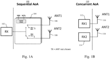
- Fig. 1A shows an example of a sequential AoA implementation 100.
- UWB-based two-dimensional AoA implementations are typically based on either concurrent operation of two receivers, wherein each receiver is connected to a separate antenna, or operation of one receiver with sequential switching of two antennas.
- the former may be referred to as a concurrent AoA implementation, while the latter may be referred to as a sequential AoA implementation.
- An example of the latter type of implementation is shown in Fig. 1A .
- an initiator typically exchanges messages containing data frames with a responder via a radio-frequency (RF) signal. If the responder comprises two receiving antennas, it can determine the two-dimensional AoA from the received RF signal.
- RF radio-frequency
- a single receiver 102 is sufficient.
- This receiver 102 is alternately coupled to a first antenna 106 and a second antenna 108 by means of controllable switches, which are included in a control block 104.
- a control circuit included in the control block may alternately open and close the switches in the paths between the receiver 102 and the first antenna 106 and between the receiver 102 and the second antenna 108.
- the respective switch When the respective switch is closed, the receiver 102 is coupled to the respective antenna.
- the respective switch is open, the receiver 102 is not coupled to the respective antenna. Instead, the respective antenna may be coupled to ground through the respective switch.
- the receiver 102 may periodically be reconnected to a different one of the antennas 106, 108, for example after a predefined number of data frames has been received. Since only a single receiver 102 is needed, the power consumption is relatively low. However, an external control block (i.e., a control block which is external to the UWB chip including the receiver 102) is typically used to control the sequential switching between the different antennas 106, 108. This may result in a higher bill of materials (BOM), a higher system complexity and a larger printed circuit board (PCB) size.
- BOM bill of materials
- PCB printed circuit board
- Fig. 1B shows an example of a concurrent AoA implementation 110.
- the concurrent AoA implementation 110 two receivers 112, 114 are used instead of one. Each of said receivers 112, 114 is coupled to a separate antenna 116, 118.
- two receivers 112, 114 are concurrently operated, and each receiver 112, 114 receives data frames through the antenna 116, 118 connected to it. This may result in a fully integrated solution in the sense that no external control block with switches is needed.
- the concurrent AoA implementation may result in a higher accuracy of the measured AoA compared to the sequential AoA implementation, but since two receivers 112, 114 are used, the power consumption is higher. This, in turn, may result in a reduced battery life in case the communication device is powered by a battery.
- a communication device and a corresponding method of operating a communication device which facilitate achieving an adequate trade-off between an acceptable power consumption and an acceptable measurement accuracy, in particular when AoA measurements are performed by the communication device.
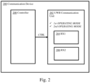
- Fig. 2 shows an illustrative embodiment of a communication device 200.
- the communication device 200 comprises a UWB communication unit 202 and a controller 208.
- the UWB communication unit 202 comprises a first receiver 204 and a second receiver 206.
- the UWB communication unit 202 is configured to enable UWB communication with at least one external communication device (not shown).
- the controller 208 is configured to control the UWB communication unit 202.
- the controller 208 is configured to cause the UWB communication unit 202, for example using a control signal, to operate in a first mode in which the first receiver 204 is alternately coupled to a first antenna and a second antenna.
- the first antenna and second antenna which are not shown, may be external to the communication device 200.
- the controller 208 is configured to cause the UWB communication unit 202 to operate in a second mode in which the first receiver 204 is coupled to the first antenna and the second receiver 206 is coupled to the second antenna.
- an adequate trade-off may be achieved between an acceptable power consumption and an acceptable accuracy.
- the UWB communication unit 202 when the UWB communication unit 202 operates in the first mode, the power consumption may be decreased, at the cost of a lower accuracy.
- the UWB communication unit 202 may be caused to operate in the second mode, in which the accuracy is higher, at the cost of a higher power consumption.
- no external control block of the kind shown in Fig. 1A is needed.
- a compact system implementation may be realized.
- the first mode of operation corresponds to a sequential AoA mode of operation and the second mode of operation corresponds to a concurrent AoA mode of operation.
- the communication device may easily be reconfigured to support different AoA modes of operation, which further facilitates achieving the desired trade-off.
- the sequential AoA mode of operation may result in a lower power consumption at the cost of a lower measurement accuracy
- the concurrent AoA mode of operation may result in a higher measurement accuracy at the cost of a higher power consumption.
- the AoA mode of operation may be changed in dependence on the application requirements.
- the first receiver is coupled to the first antenna through a first path
- the second receiver is coupled to the second antenna through a second path
- the first receiver is coupled to the second antenna through a third path.
- each of the first, second and third path comprises a matching network and a controllable switch for switching the respective path to ground.
- the controller may be configured to cause the UWB communication unit to operate in the first mode by deactivating the second receiver and by alternately switching the first path and the third path to ground, wherein the first path and third path are switched to ground by closing the controllable switch of the respective paths.
- the second receiver may be deactivated upon or after switching the second path to ground, wherein the second path is switched to ground by closing the controllable switch of said second path. Accordingly, the second receiver may be disabled after the second path has been disabled, or the second receiver and the second path may be disabled simultaneously.
- the controller may be configured to cause the UWB communication unit to operate in the second mode by switching the third path to ground, wherein the third path is switched to ground by closing the controllable switch of said third path.
- each of the first, second and third path further comprises a pre-matching network.
- a pre-matching network facilitates matching the impedance of the matching networks and switches comprised in said paths to the input impedances of the low-noise amplifiers (LNAs) comprised in the receivers.
- the controller is configured to change the mode of operation of the UWB communication unit from the first mode to the second mode, of from the second mode to the first mode, after a ranging round has been performed by the UWB communication unit. In this way, an optimal mode of operation may be selected for each ranging round to be performed.
- the controller is configured to change the mode of operation of the UWB communication unit from the first mode to the second mode, of from the second mode to the first mode, after a data frame has been received by the UWB communication unit.
- the mode of operation of the UWB communication unit can be changed frequently, for instance to take into account the accuracy requirements associated with particular data frames exchanged between the UWB communication unit and the external communication device.
- the controller is configured to change the mode of operation of the UWB communication unit in response to a control signal received from an external control system.
- the UWB communication unit further comprises a transmitter coupled to the first antenna. In this way, the UWB communication unit is also able to transmit messages, in addition to receiving messages.
- Fig. 3 shows an illustrative embodiment of a method 300 of operating a communication device.
- the method 300 comprises the following steps.
- a UWB communication unit comprised in a communication device enables UWB communication with at least one external communication device, wherein the UWB communication unit comprises a first receiver and a second receiver.
- a controller comprised in the communication device controls the UWB communication unit, wherein the controller causes the UWB communication unit to operate in a first mode in which the first receiver is alternately coupled to a first antenna and a second antenna, and in a second mode in which the first receiver is coupled to the first antenna and the second receiver is coupled to the second antenna. In this way, an adequate trade-off may be achieved between an acceptable power consumption and an acceptable accuracy.
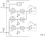
- Fig. 4 shows another illustrative embodiment of a communication device 400.
- the communication device 400 may be a UWB chip, which is connected to two antennas 406, 408.
- the communication device 400 includes a first receiver 402, which is coupled to the first antenna 406 through a first path.
- the first path contains a matching network (MN) 410, a switch 412 and an optional pre-matching network (PMN) 414.
- the communication device 400 comprises a second receiver 404, which is coupled to the second antenna 408 through a second path.
- the second path contains a matching network 422, a switch 424 and an optional pre-matching network 426.
- the first receiver 402 is coupled to the second antenna 408 through a third path, which contains a matching network 416, a switch 418 and an optional pre-matching network 420.
- the switches 412, 418, 424 of the different paths may be controlled by a controller (not shown) comprised in the communication device 400.
- the controller may cause the communication device 400 to operate in different AoA measurement modes. For example, by alternately coupling the first receiver 402 to the first antenna 406 and to the second antenna 408 through the first path and the third path, respectively, the communication device 400 may operate in a sequential AoA mode. When the communication device 400 operates in this mode, the second receiver 404 may be deactivated.
- the communication device 400 may operate in a concurrent AoA mode.
- the third path may be disabled.
- the paths may be enabled by opening the switches in said paths.
- the paths may be disabled by closing the switches in said paths, which effectively switches the paths to ground.
- the communication device 400 may be reconfigured in a flexible manner. It is noted that the communication device 400 may for example be implemented as an on-chip RF front-end module. By switching the communication device 400 into different modes of operation, both sequential AoA measurements and concurrent AoA measurements can be performed, without the need for an off-chip control block. Furthermore, it is noted that the matching networks 410, 416, 422 in the different paths ensure that, depending on the position of the switches 412, 418, 424 connected thereto, the impedance Zin seen from an antenna port into an RX chain is 50 Ohm in RX mode (when the respective switch is open) or high impedance in TX mode (when the respective switch is closed).
- the optional pre-matching network 414, 420, 426 matches the impedance of the matching network 410, 416, 422 and the switch 412, 418, 424 to the LNA input impedance. Since there are three paths, there are three input impedances Zin,1, Zin,2 and Zin,3.
- the switch configuration for supporting the sequential AoA mode of operation is shown in Table 1. It is noted that only the state of the switches of the first path (S1) and third path (S3) are shown in Table 1. For this configuration, the switch of the second path (S2) may be closed, so that the second path is effectively switched to ground, the input impedance Zin,2 is high, and the second receiver may be deactivated. Furthermore, the switch configuration for supporting the concurrent AoA mode is shown in Table 2. It is noted that only the state of the switches of the first path (S1) and second path (S2) are shown in Table 1. For this configuration, the switch of the third path (S3) may be closed, so that the third path is effectively switched to ground and impedance Zin,3 is high.
- Table 1 S1 S3 Zin,1 Zin,3 TX RX1 1 1 High-Z High-Z ANT1 - 0 1 50 Ohm High-Z - ANT1 1 0 High-Z 50 Ohm - ANT2
- Table 2 S1 S2 Zin,1 Zin,2 TX RX1 RX2 1 1 High-Z High-Z ANT1 - - 0 1 50 Ohm High-Z - ANT1 - 1 0 High-Z 50 Ohm - - ANT2
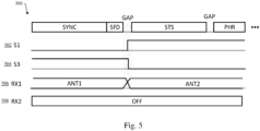
- Fig. 5 shows an illustrative embodiment of a switching sequence 500. While the switches may be configurated statically for the concurrent AoA mode, they should be configured dynamically for the sequential AoA mode. In other words, the first path and the third path should be enabled alternately, by alternately opening and closing the corresponding switches S1, S2 in a predefined manner.
- Fig. 5 shows an example of a switching sequence 500 for dynamically configuring the switches 502, 504 of the first path and the third path (S1 and S3). Initially, the first antenna (ANT1) is connected to the first receiver (RX1), while the second receiver (RX2) is deactivated, so switch S1 has the value "0" and switch S3 has the value "1".
- the antennas are switched during the gap, so that the second antenna (ANT2) is connected to the first receiver (RX1). Accordingly, switch S3 has the value "0” and switch S1 has the value "1", which activates the path from the second antenna (ANT2) to the first receiver (RX1).
- the gap during which the switching is performed facilitates the settling of transients' effects, such as impedance load changes.
- the antennas may be switched again in the second gap after the secure training sequence (STS).
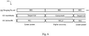
- Fig. 6 shows an illustrative embodiment of switching an operating mode 600.
- a UWB chip implementing the proposed RF front-end enables a compact AoA system where AoA accuracy can be traded with power consumption during operation.
- the responder chip may switch the AoA mode during operation as follows.
- a first ranging round (RR1) the chip is configured in a sequential AoA mode, in which it has a lower power consumption at the expense of a slightly lower accuracy.
- the switching between the different antennas in the sequential AoA mode may be performed as described as above.
- a second ranging round the chip is configured in a concurrent AoA mode, in which it has a higher accuracy, but also a higher current consumption.
- a third ranging round the chip is again configured in the sequential AoA mode.
- the mode switching may not only be performed between ranging rounds, but also between data frames.
- the mode switching may be triggered by an external signal, for example a signal indicating that higher AoA accuracy is needed.
- the front-end may easily be extended to cover additional RF pins and receiver chains, for example to support on-chip sequential and concurrent three-dimensional AoA measurements.
- an additional transmitter may be connected to the second antenna.
- the systems and methods described herein may at least partially be embodied by a computer program or a plurality of computer programs, which may exist in a variety of forms both active and inactive in a single computer system or across multiple computer systems.
- they may exist as software program(s) comprised of program instructions in source code, object code, executable code or other formats for performing some of the steps.
- Any of the above may be embodied on a computer-readable medium, which may include storage devices and signals, in compressed or uncompressed form.
- the term "computer” refers to any electronic device comprising a processor, such as a general-purpose central processing unit (CPU), a specific-purpose processor or a microcontroller.
- a computer is capable of receiving data (an input), of performing a sequence of predetermined operations thereupon, and of producing thereby a result in the form of information or signals (an output).
- the term "computer” will mean either a processor in particular or more generally a processor in association with an assemblage of interrelated elements contained within a single case or housing.
- processor or “processing unit” refers to a data processing circuit that may be a microprocessor, a co-processor, a microcontroller, a microcomputer, a central processing unit, a field programmable gate array (FPGA), a programmable logic circuit, and/or any circuit that manipulates signals (analog or digital) based on operational instructions that are stored in a memory.
- memory refers to a storage circuit or multiple storage circuits such as read-only memory, random access memory, volatile memory, non-volatile memory, static memory, dynamic memory, Flash memory, cache memory, and/or any circuit that stores digital information.
- a "computer-readable medium” or “storage medium” may be any means that can contain, store, communicate, propagate, or transport a computer program for use by or in connection with the instruction execution system, apparatus, or device.
- the computer-readable medium may be, for example but not limited to, an electronic, magnetic, optical, electromagnetic, infrared, or semiconductor system, apparatus, device, or propagation medium.
- the computer-readable medium may include the following: an electrical connection having one or more wires, a portable computer diskette, a random-access memory (RAM), a read-only memory (ROM), an erasable programmable read-only memory (EPROM or Flash memory), an optical fiber, a portable compact disc read-only memory (CDROM), a digital versatile disc (DVD), a Blu-ray disc (BD), and a memory card.
- RAM random-access memory
- ROM read-only memory
- EPROM or Flash memory erasable programmable read-only memory
- CDROM compact disc read-only memory
- DVD digital versatile disc
- BD Blu-ray disc
Landscapes
- Engineering & Computer Science (AREA)
- Radar, Positioning & Navigation (AREA)
- Remote Sensing (AREA)
- Computer Networks & Wireless Communication (AREA)
- Physics & Mathematics (AREA)
- General Physics & Mathematics (AREA)
- Signal Processing (AREA)
- Mobile Radio Communication Systems (AREA)
- Variable-Direction Aerials And Aerial Arrays (AREA)
Abstract
Description
- The present disclosure relates to a communication device. Furthermore, the present disclosure relates to a corresponding method of operating a communication device, and to a computer program for carrying out said method.
- Ultra-wideband (UWB) communication technology is a technology that uses a high signal bandwidth, in particular for transmitting digital data over a wide spectrum of frequency bands with very low power. For example, UWB technology may use the frequency spectrum of 3.1 to 10.6 GHz and may feature a high-frequency bandwidth of more than 500 MHz and very short pulse signals, potentially capable of supporting high data rates. The UWB technology enables a high data throughput for communication devices and a high precision for the localization of devices. In particular, UWB technology may be used for so-called ranging operations, i.e. for determining the distance between communicating devices. Therefore, UWB technology may be used to advantage in various applications, such as automotive applications.
- In accordance with a first aspect of the present disclosure, a communication device is provided, comprising: an ultra-wideband (UWB) communication unit configured to enable UWB communication with at least one external communication device, the UWB communication unit comprising a first receiver and a second receiver; a controller configured to control the UWB communication unit; wherein the controller is configured to cause the UWB communication unit to operate in a first mode in which the first receiver is alternately coupled to a first antenna and a second antenna; and wherein the controller is configured to cause the UWB communication unit to operate in a second mode in which the first receiver is coupled to the first antenna and the second receiver is coupled to the second antenna.
- In one or more embodiments, the first mode of operation corresponds to a sequential angle-of-arrival (AoA) mode of operation and the second mode of operation corresponds to a concurrent AoA mode of operation.
- In one or more embodiments, the first receiver is coupled to the first antenna through a first path; the second receiver is coupled to the second antenna through a second path; the first receiver is coupled to the second antenna through a third path; wherein each of the first, second and third path comprises a matching network and a controllable switch for switching the respective path to ground.
- In one or more embodiments, the controller is configured to cause the UWB communication unit to operate in the first mode by deactivating the second receiver and by alternately switching the first path and the third path to ground, wherein the first path and third path are switched to ground by closing the controllable switch of the respective paths.
- In one or more embodiments, the second receiver is deactivated upon or after switching the second path to ground, wherein the second path is switched to ground by closing the controllable switch of said second path.
- In one or more embodiments, the controller is configured to cause the UWB communication unit to operate in the second mode by switching the third path to ground, wherein the third path is switched to ground by closing the controllable switch of said third path.
- In one or more embodiments, each of the first, second and third path further comprises a pre-matching network.
- In one or more embodiments, the controller is configured to change the mode of operation of the UWB communication unit from the first mode to the second mode, of from the second mode to the first mode, after a ranging round has been performed by the UWB communication unit.
- In one or more embodiments, the controller is configured to change the mode of operation of the UWB communication unit from the first mode to the second mode, of from the second mode to the first mode, after a data frame has been received by the UWB communication unit.
- In one or more embodiments, the controller is configured to change the mode of operation of the UWB communication unit in response to a control signal received from an external control system.
- In one or more embodiments, the UWB communication unit further comprises a transmitter coupled to the first antenna.
- In accordance with a second aspect of the present disclosure, a method of operating a communication device is conceived, comprising: enabling, by an ultra-wideband, UWB, communication unit comprised in the communication device, UWB communication with at least one external communication device, the UWB communication unit comprising a first receiver and a second receiver; controlling, by a controller comprised in the communication device, the UWB communication unit, wherein the controller causes the UWB communication unit to operate in a first mode in which the first receiver is alternately coupled to a first antenna and a second antenna, and in a second mode in which the first receiver is coupled to the first antenna and the second receiver is coupled to the second antenna.
- In one or more embodiments, the controller changes the mode of operation of the UWB communication unit from the first mode to the second mode, of from the second mode to the first mode, after a ranging round has been performed by the UWB communication unit.
- In one or more embodiments, the controller changes the mode of operation of the UWB communication unit from the first mode to the second mode, of from the second mode to the first mode, after a data frame has been received by the UWB communication unit.
- In accordance with a third aspect of the present disclosure, a computer program is provided, comprising executable instructions which, when executed by a controller of a communication device, cause said controller to perform a method of the kind set forth.
- Embodiments will be described in more detail with reference to the appended drawings, in which:
-
Fig. 1A shows an example of a sequential AoA implementation; -
Fig. 1B shows an example of a concurrent AoA implementation; -
Fig. 2 shows an illustrative embodiment of a communication device; -
Fig. 3 shows an illustrative embodiment of a method of operating a communication device; -
Fig. 4 shows another illustrative embodiment of a communication device; -
Fig. 5 shows an illustrative embodiment of a switching sequence; -
Fig. 6 shows an illustrative embodiment of switching an operating mode. - As mentioned above, UWB is a technology that uses a high signal bandwidth, in particular for transmitting digital data over a wide spectrum of frequency bands with very low power. For example, UWB technology may use the frequency spectrum of 3.1 to 10.6 GHz and may feature a high-frequency bandwidth of more than 500 MHz and very short pulse signals, potentially capable of supporting high data rates. The UWB technology enables a high data throughput for communication devices and a high precision for the localization of devices. In particular, UWB technology may be used for so-called ranging operations, i.e. for determining the distance between communicating devices. Therefore, UWB technology may be used to advantage in various applications, such as automotive applications. For example, smart vehicle access systems may employ UWB technology to enable access to a vehicle or another object, in particular by facilitating ranging operations between an access device (e.g. a key fob or a mobile device) and one or more UWB anchors in the vehicle or other object.
- In particular, UWB technology - also referred to as impulse-radio ultra-wideband (IR-UWB) - is a RF communication technology that uses pulses having a short duration for data communication. An important feature of IR-UWB technology is that it can be used for secure and accurate distance measurements between two or more devices. Typical distance measurement methods are the so-called single-sided two-way ranging (SS-TWR) method and the double-sided two-way ranging (DS-TWR) method.
- Because UWB technology has an accurate distance measurement capability, it may be used to advantage in access systems in which the position of devices should be determined to enable access to an object. For instance, a vehicle access system may comprise a user's smart device (e.g., key fob) and another smart device (e.g., an anchor embedded in the vehicle). To enable access to the vehicle, the user's smart device must have a predefined range relative to the other smart device. Therefore, UWB transceivers are typically configured to operate in a ranging mode. In another example, UWB technology may be used for accessing a building or a predefined space within a building.
- In the ranging mode of operation, frames will typically be exchanged between two devices via at least one antenna on each device, and at least a SS-TWR operation will be carried out (which may also be referred to as a ping-pong operation). In particular, channel impulse responses (CIRs) are estimated on both devices, timestamps will be generated based on the CIRs on both devices, and those timestamps are exchanged. Then, a time of flight (ToF) is calculated based on the timestamps and a range (i.e., a distance) is calculated based on the ToF. Alternatively, a DS-TWR operation may be carried out (which may also be referred to as a ping-pong-ping operation). The angle-of-arrival (AoA) mode of operation is similar to the ranging mode, but it involves at least two antennas on one device. In particular, in the AoA mode of operation, two phase values associated with at least two CIRs are calculated on one device. Then, a phase difference of arrival (PDoA) is calculated based on the two-phase values, and an AoA is calculated based on the PDoA. The AoA mode of operation may facilitate a more accurate determination of the position of an object and may thus complement ranging operations performed in the ranging mode.
-
Fig. 1A shows an example of asequential AoA implementation 100. It is noted that UWB-based two-dimensional AoA implementations are typically based on either concurrent operation of two receivers, wherein each receiver is connected to a separate antenna, or operation of one receiver with sequential switching of two antennas. The former may be referred to as a concurrent AoA implementation, while the latter may be referred to as a sequential AoA implementation. An example of the latter type of implementation is shown inFig. 1A . In UWB systems an initiator typically exchanges messages containing data frames with a responder via a radio-frequency (RF) signal. If the responder comprises two receiving antennas, it can determine the two-dimensional AoA from the received RF signal. In thesequential AoA implementation 100, asingle receiver 102 is sufficient. Thisreceiver 102 is alternately coupled to afirst antenna 106 and asecond antenna 108 by means of controllable switches, which are included in acontrol block 104. For example, a control circuit included in the control block may alternately open and close the switches in the paths between thereceiver 102 and thefirst antenna 106 and between thereceiver 102 and thesecond antenna 108. When the respective switch is closed, thereceiver 102 is coupled to the respective antenna. Furthermore, when the respective switch is open, thereceiver 102 is not coupled to the respective antenna. Instead, the respective antenna may be coupled to ground through the respective switch. Thus, thereceiver 102 may periodically be reconnected to a different one of theantennas single receiver 102 is needed, the power consumption is relatively low. However, an external control block (i.e., a control block which is external to the UWB chip including the receiver 102) is typically used to control the sequential switching between thedifferent antennas -
Fig. 1B shows an example of aconcurrent AoA implementation 110. In theconcurrent AoA implementation 110, tworeceivers receivers separate antenna receivers receiver antenna receivers - Now discussed are a communication device and a corresponding method of operating a communication device, which facilitate achieving an adequate trade-off between an acceptable power consumption and an acceptable measurement accuracy, in particular when AoA measurements are performed by the communication device.
-
Fig. 2 shows an illustrative embodiment of acommunication device 200. Thecommunication device 200 comprises aUWB communication unit 202 and acontroller 208. TheUWB communication unit 202 comprises afirst receiver 204 and asecond receiver 206. TheUWB communication unit 202 is configured to enable UWB communication with at least one external communication device (not shown). Furthermore, thecontroller 208 is configured to control theUWB communication unit 202. In particular, thecontroller 208 is configured to cause theUWB communication unit 202, for example using a control signal, to operate in a first mode in which thefirst receiver 204 is alternately coupled to a first antenna and a second antenna. It is noted that the first antenna and second antenna, which are not shown, may be external to thecommunication device 200. For instance, if thecommunication device 200 is implemented as a UWB chip, the antennas are typically not integrated into the chip. Furthermore, thecontroller 208 is configured to cause theUWB communication unit 202 to operate in a second mode in which thefirst receiver 204 is coupled to the first antenna and thesecond receiver 206 is coupled to the second antenna. In this way, an adequate trade-off may be achieved between an acceptable power consumption and an acceptable accuracy. In particular, when theUWB communication unit 202 operates in the first mode, the power consumption may be decreased, at the cost of a lower accuracy. However, in case a higher accuracy is needed, theUWB communication unit 202 may be caused to operate in the second mode, in which the accuracy is higher, at the cost of a higher power consumption. Furthermore, in order to achieve said trade-off, no external control block of the kind shown inFig. 1A is needed. Thus, a compact system implementation may be realized. - In one or more embodiments, the first mode of operation corresponds to a sequential AoA mode of operation and the second mode of operation corresponds to a concurrent AoA mode of operation. In this way, the communication device may easily be reconfigured to support different AoA modes of operation, which further facilitates achieving the desired trade-off. In particular, the sequential AoA mode of operation may result in a lower power consumption at the cost of a lower measurement accuracy, while the concurrent AoA mode of operation may result in a higher measurement accuracy at the cost of a higher power consumption. It is noted that the AoA mode of operation may be changed in dependence on the application requirements.
- In one or more embodiments, the first receiver is coupled to the first antenna through a first path, the second receiver is coupled to the second antenna through a second path, and the first receiver is coupled to the second antenna through a third path. In these embodiments, each of the first, second and third path comprises a matching network and a controllable switch for switching the respective path to ground. In this way, the UWB communication unit may easily be controlled, i.e. caused to operate in the desired mode. More specifically, the respective path may be switched to ground via the switch, and the matching network may transform this ground into a high impedance (Zin = "High-Z") that is seen when looking into this path, thereby effectively disabling said path. It is noted that a high impedance means that no RF current can flow into the path. In particular, the controller may be configured to cause the UWB communication unit to operate in the first mode by deactivating the second receiver and by alternately switching the first path and the third path to ground, wherein the first path and third path are switched to ground by closing the controllable switch of the respective paths. Furthermore, the second receiver may be deactivated upon or after switching the second path to ground, wherein the second path is switched to ground by closing the controllable switch of said second path. Accordingly, the second receiver may be disabled after the second path has been disabled, or the second receiver and the second path may be disabled simultaneously. Furthermore, the controller may be configured to cause the UWB communication unit to operate in the second mode by switching the third path to ground, wherein the third path is switched to ground by closing the controllable switch of said third path. This may result in a practical implementation of the presently disclosed communication device.
- In one or more embodiments, each of the first, second and third path further comprises a pre-matching network. The use of a pre-matching network facilitates matching the impedance of the matching networks and switches comprised in said paths to the input impedances of the low-noise amplifiers (LNAs) comprised in the receivers. In one or more embodiments, the controller is configured to change the mode of operation of the UWB communication unit from the first mode to the second mode, of from the second mode to the first mode, after a ranging round has been performed by the UWB communication unit. In this way, an optimal mode of operation may be selected for each ranging round to be performed. Furthermore, in one or more embodiments, the controller is configured to change the mode of operation of the UWB communication unit from the first mode to the second mode, of from the second mode to the first mode, after a data frame has been received by the UWB communication unit. In this way, the mode of operation of the UWB communication unit can be changed frequently, for instance to take into account the accuracy requirements associated with particular data frames exchanged between the UWB communication unit and the external communication device. In a practical implementation, the controller is configured to change the mode of operation of the UWB communication unit in response to a control signal received from an external control system. Furthermore, in one or more embodiments, the UWB communication unit further comprises a transmitter coupled to the first antenna. In this way, the UWB communication unit is also able to transmit messages, in addition to receiving messages.
-
Fig. 3 shows an illustrative embodiment of amethod 300 of operating a communication device. Themethod 300 comprises the following steps. At 302, a UWB communication unit comprised in a communication device enables UWB communication with at least one external communication device, wherein the UWB communication unit comprises a first receiver and a second receiver. Furthermore, at 304, a controller comprised in the communication device controls the UWB communication unit, wherein the controller causes the UWB communication unit to operate in a first mode in which the first receiver is alternately coupled to a first antenna and a second antenna, and in a second mode in which the first receiver is coupled to the first antenna and the second receiver is coupled to the second antenna. In this way, an adequate trade-off may be achieved between an acceptable power consumption and an acceptable accuracy. -
Fig. 4 shows another illustrative embodiment of acommunication device 400. Thecommunication device 400 may be a UWB chip, which is connected to twoantennas communication device 400 includes afirst receiver 402, which is coupled to thefirst antenna 406 through a first path. The first path contains a matching network (MN) 410, aswitch 412 and an optional pre-matching network (PMN) 414. Furthermore, thecommunication device 400 comprises asecond receiver 404, which is coupled to thesecond antenna 408 through a second path. The second path contains amatching network 422, aswitch 424 and an optionalpre-matching network 426. Furthermore, thefirst receiver 402 is coupled to thesecond antenna 408 through a third path, which contains amatching network 416, aswitch 418 and an optionalpre-matching network 420. Theswitches communication device 400. By controlling theswitches communication device 400 to operate in different AoA measurement modes. For example, by alternately coupling thefirst receiver 402 to thefirst antenna 406 and to thesecond antenna 408 through the first path and the third path, respectively, thecommunication device 400 may operate in a sequential AoA mode. When thecommunication device 400 operates in this mode, thesecond receiver 404 may be deactivated. Furthermore, by coupling thefirst receiver 402 to thefirst antenna 406 through the first path and thesecond receiver 404 to thesecond antenna 404 through the second path, thecommunication device 400 may operate in a concurrent AoA mode. In that case, the third path may be disabled. It is noted that the paths may be enabled by opening the switches in said paths. Furthermore, the paths may be disabled by closing the switches in said paths, which effectively switches the paths to ground. - Accordingly, the
communication device 400 may be reconfigured in a flexible manner. It is noted that thecommunication device 400 may for example be implemented as an on-chip RF front-end module. By switching thecommunication device 400 into different modes of operation, both sequential AoA measurements and concurrent AoA measurements can be performed, without the need for an off-chip control block. Furthermore, it is noted that thematching networks switches pre-matching network matching network switch - The switch configuration for supporting the sequential AoA mode of operation is shown in Table 1. It is noted that only the state of the switches of the first path (S1) and third path (S3) are shown in Table 1. For this configuration, the switch of the second path (S2) may be closed, so that the second path is effectively switched to ground, the input impedance Zin,2 is high, and the second receiver may be deactivated. Furthermore, the switch configuration for supporting the concurrent AoA mode is shown in Table 2. It is noted that only the state of the switches of the first path (S1) and second path (S2) are shown in Table 1. For this configuration, the switch of the third path (S3) may be closed, so that the third path is effectively switched to ground and impedance Zin,3 is high. In Table 1 and Table 2, the value "0" indicates that a switch is open, while the value "1" indicates that a switch is closed.
Table 1 S1 S3 Zin,1 Zin,3 TX RX1 1 1 High-Z High-Z ANT1 - 0 1 50 Ohm High-Z - ANT1 1 0 High-Z 50 Ohm - ANT2 Table 2 S1 S2 Zin,1 Zin,2 TX RX1 RX2 1 1 High-Z High-Z ANT1 - - 0 1 50 Ohm High-Z - ANT1 - 1 0 High-Z 50 Ohm - - ANT2 -
Fig. 5 shows an illustrative embodiment of aswitching sequence 500. While the switches may be configurated statically for the concurrent AoA mode, they should be configured dynamically for the sequential AoA mode. In other words, the first path and the third path should be enabled alternately, by alternately opening and closing the corresponding switches S1, S2 in a predefined manner.Fig. 5 shows an example of aswitching sequence 500 for dynamically configuring theswitches -
Fig. 6 shows an illustrative embodiment of switching anoperating mode 600. In particular, it is shown how a UWB chip implementing the proposed RF front-end enables a compact AoA system where AoA accuracy can be traded with power consumption during operation. Assuming that an initiator performs multiple ranging rounds (RR) with a responder, the responder chip may switch the AoA mode during operation as follows. In a first ranging round (RR1) the chip is configured in a sequential AoA mode, in which it has a lower power consumption at the expense of a slightly lower accuracy. The switching between the different antennas in the sequential AoA mode may be performed as described as above. In a second ranging round (RR2) the chip is configured in a concurrent AoA mode, in which it has a higher accuracy, but also a higher current consumption. Finally, in a third ranging round (RR3) the chip is again configured in the sequential AoA mode. In general, there may be an arbitrary sequence of sequential-to-concurrent and concurrent-to-sequential mode transitions. Furthermore, the mode switching may not only be performed between ranging rounds, but also between data frames. In addition, the mode switching may be triggered by an external signal, for example a signal indicating that higher AoA accuracy is needed. It is noted that the front-end may easily be extended to cover additional RF pins and receiver chains, for example to support on-chip sequential and concurrent three-dimensional AoA measurements. Furthermore, an additional transmitter may be connected to the second antenna. - The systems and methods described herein may at least partially be embodied by a computer program or a plurality of computer programs, which may exist in a variety of forms both active and inactive in a single computer system or across multiple computer systems. For example, they may exist as software program(s) comprised of program instructions in source code, object code, executable code or other formats for performing some of the steps. Any of the above may be embodied on a computer-readable medium, which may include storage devices and signals, in compressed or uncompressed form.
- As used herein, the term "computer" refers to any electronic device comprising a processor, such as a general-purpose central processing unit (CPU), a specific-purpose processor or a microcontroller. A computer is capable of receiving data (an input), of performing a sequence of predetermined operations thereupon, and of producing thereby a result in the form of information or signals (an output). Depending on the context, the term "computer" will mean either a processor in particular or more generally a processor in association with an assemblage of interrelated elements contained within a single case or housing.
- The term "processor" or "processing unit" refers to a data processing circuit that may be a microprocessor, a co-processor, a microcontroller, a microcomputer, a central processing unit, a field programmable gate array (FPGA), a programmable logic circuit, and/or any circuit that manipulates signals (analog or digital) based on operational instructions that are stored in a memory. The term "memory" refers to a storage circuit or multiple storage circuits such as read-only memory, random access memory, volatile memory, non-volatile memory, static memory, dynamic memory, Flash memory, cache memory, and/or any circuit that stores digital information.
- As used herein, a "computer-readable medium" or "storage medium" may be any means that can contain, store, communicate, propagate, or transport a computer program for use by or in connection with the instruction execution system, apparatus, or device. The computer-readable medium may be, for example but not limited to, an electronic, magnetic, optical, electromagnetic, infrared, or semiconductor system, apparatus, device, or propagation medium. More specific examples (non-exhaustive list) of the computer-readable medium may include the following: an electrical connection having one or more wires, a portable computer diskette, a random-access memory (RAM), a read-only memory (ROM), an erasable programmable read-only memory (EPROM or Flash memory), an optical fiber, a portable compact disc read-only memory (CDROM), a digital versatile disc (DVD), a Blu-ray disc (BD), and a memory card.
- It is noted that the embodiments above have been described with reference to different subject-matters. In particular, some embodiments may have been described with reference to method-type claims whereas other embodiments may have been described with reference to apparatus-type claims. However, a person skilled in the art will gather from the above that, unless otherwise indicated, in addition to any combination of features belonging to one type of subject-matter also any combination of features relating to different subject-matters, in particular a combination of features of the method-type claims and features of the apparatus-type claims, is considered to be disclosed with this document.
- Furthermore, it is noted that the drawings are schematic. In different drawings, similar or identical elements are provided with the same reference signs. Furthermore, it is noted that in an effort to provide a concise description of the illustrative embodiments, implementation details which fall into the customary practice of the skilled person may not have been described. It should be appreciated that in the development of any such implementation, as in any engineering or design project, numerous implementation-specific decisions must be made in order to achieve the developers' specific goals, such as compliance with system-related and business-related constraints, which may vary from one implementation to another. Moreover, it should be appreciated that such a development effort might be complex and time consuming, but would nevertheless be a routine undertaking of design, fabrication, and manufacture for those of ordinary skill.
- Finally, it is noted that the skilled person will be able to design many alternative embodiments without departing from the scope of the appended claims. In the claims, any reference sign placed between parentheses shall not be construed as limiting the claim. The word "comprise(s)" or "comprising" does not exclude the presence of elements or steps other than those listed in a claim. The word "a" or "an" preceding an element does not exclude the presence of a plurality of such elements. Measures recited in the claims may be implemented by means of hardware comprising several distinct elements and/or by means of a suitably programmed processor. In a device claim enumerating several means, several of these means may be embodied by one and the same item of hardware. The mere fact that certain measures are recited in mutually different dependent claims does not indicate that a combination of these measures cannot be used to advantage.
-
- 100
- sequential AoA implementation
- 102
- receiver
- 104
- control block
- 106
- antenna
- 108
- antenna
- 110
- concurrent AoA implementation
- 112
- receiver
- 114
- receiver
- 116
- antenna
- 118
- antenna
- 200
- communication device
- 202
- UWB communication unit
- 204
- receiver
- 206
- receiver
- 208
- controller
- 300
- method of operating a communication device
- 302
- enabling, by an ultra-wideband, UWB, communication unit comprised in a communication device, UWB communication with at least one external communication device, the UWB communication unit comprising a first receiver and a second receiver
- 304
- controlling, by a controller comprised in the communication device, the UWB communication unit, wherein the controller causes the UWB communication unit to operate in a first mode in which the first receiver is alternately coupled to a first antenna and a second antenna, and in a second mode in which the first receiver is coupled to the first antenna and the second receiver is coupled to the second antenna
- 400
- communication device
- 402
- receiver
- 404
- receiver
- 406
- antenna
- 408
- antenna
- 410
- matching network
- 412
- controllable switch
- 414
- pre-matching network
- 416
- matching network
- 418
- controllable switch
- 420
- pre-matching network
- 422
- matching network
- 424
- controllable switch
- 426
- pre-matching network
- 500
- switching sequence
- 502
- control signal for switch
- 504
- control signal for switch
- 506
- receiver state
- 508
- receiver state
- 600
- operating mode switching
- 602
- ranging round
- 604
- AoA mode
- 606
- active receiver
Claims (15)
- A communication device, comprising:- an ultra-wideband, UWB, communication unit configured to enable UWB communication with at least one external communication device, the UWB communication unit comprising a first receiver and a second receiver;- a controller configured to control the UWB communication unit;wherein the controller is configured to cause the UWB communication unit to operate in a first mode in which the first receiver is alternately coupled to a first antenna and a second antenna; andwherein the controller is configured to cause the UWB communication unit to operate in a second mode in which the first receiver is coupled to the first antenna and the second receiver is coupled to the second antenna.
- The communication device of claim 1, wherein the first mode of operation corresponds to a sequential angle-of-arrival, AoA, mode of operation and the second mode of operation corresponds to a concurrent AoA mode of operation.
- The communication device of claim 1 or 2, wherein:the first receiver is coupled to the first antenna through a first path;the second receiver is coupled to the second antenna through a second path;the first receiver is coupled to the second antenna through a third path; andwherein each of the first, second and third path comprises a matching network and a controllable switch for switching the respective path to ground.
- The communication device of claim 3, wherein the controller is configured to cause the UWB communication unit to operate in the first mode by deactivating the second receiver and by alternately switching the first path and the third path to ground,
wherein the first path and third path are switched to ground by closing the controllable switch of the respective paths. - The communication device of claim 4, wherein the second receiver is deactivated upon or after switching the second path to ground, wherein the second path is switched to ground by closing the controllable switch of said second path.
- The communication device of any one of claims 3 to 5, wherein the controller is configured to cause the UWB communication unit to operate in the second mode by switching the third path to ground, wherein the third path is switched to ground by closing the controllable switch of said third path.
- The communication device of any one of claims 3 to 6, wherein each of the first, second and third path further comprises a pre-matching network.
- The communication device of any preceding claim, wherein the controller is configured to change the mode of operation of the UWB communication unit from the first mode to the second mode, of from the second mode to the first mode, after a ranging round has been performed by the UWB communication unit.
- The communication device of any preceding claim, wherein the controller is configured to change the mode of operation of the UWB communication unit from the first mode to the second mode, of from the second mode to the first mode, after a data frame has been received by the UWB communication unit.
- The communication device of claim 8 or 9, wherein the controller is configured to change the mode of operation of the UWB communication unit in response to a control signal received from an external control system.
- The communication device of any preceding claim, wherein the UWB communication unit further comprises a transmitter coupled to the first antenna.
- A method of operating a communication device, comprising:- enabling, by an ultra-wideband, UWB, communication unit comprised in the communication device, UWB communication with at least one external communication device, the UWB communication unit comprising a first receiver and a second receiver;- controlling, by a controller comprised in the communication device, the UWB communication unit, wherein the controller causes the UWB communication unit to operate in a first mode in which the first receiver is alternately coupled to a first antenna and a second antenna, and in a second mode in which the first receiver is coupled to the first antenna and the second receiver is coupled to the second antenna.
- The method of claim 12, wherein the controller changes the mode of operation of the UWB communication unit from the first mode to the second mode, of from the second mode to the first mode, after a ranging round has been performed by the UWB communication unit.
- The method claim 12 or 13, wherein the controller changes the mode of operation of the UWB communication unit from the first mode to the second mode, of from the second mode to the first mode, after a data frame has been received by the UWB communication unit.
- A computer program comprising executable instructions which, when executed by a controller of a communication device, cause said controller to perform the method of any one of claims 12 to 14.
Priority Applications (3)
| Application Number | Priority Date | Filing Date | Title |
|---|---|---|---|
| EP21192468.3A EP4137836B1 (en) | 2021-08-20 | 2021-08-20 | Communication device and corresponding operating method |
| US17/817,372 US12519229B2 (en) | 2021-08-20 | 2022-08-04 | Communication device and corresponding operating method |
| CN202210946516.XA CN115708393A (en) | 2021-08-20 | 2022-08-05 | Communication device and corresponding operating method |
Applications Claiming Priority (1)
| Application Number | Priority Date | Filing Date | Title |
|---|---|---|---|
| EP21192468.3A EP4137836B1 (en) | 2021-08-20 | 2021-08-20 | Communication device and corresponding operating method |
Publications (2)
| Publication Number | Publication Date |
|---|---|
| EP4137836A1 true EP4137836A1 (en) | 2023-02-22 |
| EP4137836B1 EP4137836B1 (en) | 2025-07-02 |
Family
ID=77543304
Family Applications (1)
| Application Number | Title | Priority Date | Filing Date |
|---|---|---|---|
| EP21192468.3A Active EP4137836B1 (en) | 2021-08-20 | 2021-08-20 | Communication device and corresponding operating method |
Country Status (3)
| Country | Link |
|---|---|
| US (1) | US12519229B2 (en) |
| EP (1) | EP4137836B1 (en) |
| CN (1) | CN115708393A (en) |
Families Citing this family (2)
| Publication number | Priority date | Publication date | Assignee | Title |
|---|---|---|---|---|
| EP4164134B1 (en) * | 2021-10-06 | 2025-07-02 | Nxp B.V. | Communication device and operating method |
| US12555928B2 (en) * | 2023-02-27 | 2026-02-17 | Hewlett-Packard Development Company, L.P. | Antenna switching |
Citations (2)
| Publication number | Priority date | Publication date | Assignee | Title |
|---|---|---|---|---|
| US9369173B1 (en) * | 2015-02-11 | 2016-06-14 | Broadcom Corporation | Directional antenna isolation structure |
| US20210076350A1 (en) * | 2019-09-09 | 2021-03-11 | Samsung Electronics Co., Ltd. | Electronic device and method for position determination using uwb signal |
Family Cites Families (7)
| Publication number | Priority date | Publication date | Assignee | Title |
|---|---|---|---|---|
| US8000737B2 (en) * | 2004-10-15 | 2011-08-16 | Sky Cross, Inc. | Methods and apparatuses for adaptively controlling antenna parameters to enhance efficiency and maintain antenna size compactness |
| US9287953B2 (en) * | 2012-05-21 | 2016-03-15 | Qualcomm Incorporated | Systems, apparatus, and methods for antenna selection |
| US9070974B2 (en) * | 2012-05-21 | 2015-06-30 | Qualcomm Incorporated | Antenna switching devices, methods, and systems for simultaneous communication |
| US10141958B2 (en) * | 2016-02-19 | 2018-11-27 | Psemi Corporation | Adaptive tuning network for combinable filters |
| EP3493426B1 (en) | 2017-12-01 | 2020-06-17 | Nxp B.V. | A receiver-system |
| EP3609085B1 (en) | 2018-08-07 | 2021-02-24 | Nxp B.V. | Rf switching |
| EP4002702B1 (en) | 2020-11-20 | 2024-10-02 | Nxp B.V. | A receive path |
-
2021
- 2021-08-20 EP EP21192468.3A patent/EP4137836B1/en active Active
-
2022
- 2022-08-04 US US17/817,372 patent/US12519229B2/en active Active
- 2022-08-05 CN CN202210946516.XA patent/CN115708393A/en active Pending
Patent Citations (2)
| Publication number | Priority date | Publication date | Assignee | Title |
|---|---|---|---|---|
| US9369173B1 (en) * | 2015-02-11 | 2016-06-14 | Broadcom Corporation | Directional antenna isolation structure |
| US20210076350A1 (en) * | 2019-09-09 | 2021-03-11 | Samsung Electronics Co., Ltd. | Electronic device and method for position determination using uwb signal |
Non-Patent Citations (1)
| Title |
|---|
| HEYDARIAAN MILAD ET AL: "AnguLoc: Concurrent Angle of Arrival Estimation for Indoor Localization with UWB Radios", 2020 16TH INTERNATIONAL CONFERENCE ON DISTRIBUTED COMPUTING IN SENSOR SYSTEMS (DCOSS), IEEE, 25 May 2020 (2020-05-25), pages 112 - 119, XP033819298, DOI: 10.1109/DCOSS49796.2020.00028 * |
Also Published As
| Publication number | Publication date |
|---|---|
| US12519229B2 (en) | 2026-01-06 |
| US20230065673A1 (en) | 2023-03-02 |
| EP4137836B1 (en) | 2025-07-02 |
| CN115708393A (en) | 2023-02-21 |
Similar Documents
| Publication | Publication Date | Title |
|---|---|---|
| US9048882B2 (en) | Near field communications (NFC) and proximity sensor for portable devices | |
| US12481052B2 (en) | Localization with reduced power consumption | |
| US12519229B2 (en) | Communication device and corresponding operating method | |
| EP2628249B1 (en) | Integrated circuit device, wireless communication unit and method of manufacture therefor | |
| EP2883275B1 (en) | Front end parallel resonant switch | |
| US12255679B2 (en) | Radio frequency circuit and electronic device | |
| US9031518B2 (en) | Concurrent hybrid matching network | |
| US11973551B2 (en) | Communication device and operating method | |
| EP4184195B1 (en) | System and method for facilitating detecting an external object | |
| US12047113B2 (en) | Communication device and operating method | |
| CN113258960A (en) | Communication device and operation method thereof | |
| EP3911038B1 (en) | Method for controlling transmit power of wireless communications terminal, and wireless communications terminal | |
| JP6585125B2 (en) | Near field communication (NFC) and proximity sensors for portable devices | |
| US20060145859A1 (en) | RFID antenna assembly with integrated status indicator | |
| US20240295648A1 (en) | Communication devices and operating methods | |
| JP6178379B2 (en) | Near field communication (NFC) and proximity sensors for portable devices | |
| CN118283571A (en) | A UWB-based vehicle communication method, device and computing equipment | |
| KR100729341B1 (en) | Wireless communication signal transmission / reception path selector | |
| CN114374417A (en) | Antenna detection method and device, electronic equipment and storage medium | |
| CN114665907A (en) | Radio frequency system and communication equipment | |
| KR200426555Y1 (en) | Wireless communication signal transmission / reception path selector | |
| CN116299398A (en) | Target ranging method and device applied to aircraft and electronic equipment |
Legal Events
| Date | Code | Title | Description |
|---|---|---|---|
| PUAI | Public reference made under article 153(3) epc to a published international application that has entered the european phase |
Free format text: ORIGINAL CODE: 0009012 |
|
| STAA | Information on the status of an ep patent application or granted ep patent |
Free format text: STATUS: THE APPLICATION HAS BEEN PUBLISHED |
|
| AK | Designated contracting states |
Kind code of ref document: A1 Designated state(s): AL AT BE BG CH CY CZ DE DK EE ES FI FR GB GR HR HU IE IS IT LI LT LU LV MC MK MT NL NO PL PT RO RS SE SI SK SM TR |
|
| STAA | Information on the status of an ep patent application or granted ep patent |
Free format text: STATUS: REQUEST FOR EXAMINATION WAS MADE |
|
| 17P | Request for examination filed |
Effective date: 20230822 |
|
| RBV | Designated contracting states (corrected) |
Designated state(s): AL AT BE BG CH CY CZ DE DK EE ES FI FR GB GR HR HU IE IS IT LI LT LU LV MC MK MT NL NO PL PT RO RS SE SI SK SM TR |
|
| GRAP | Despatch of communication of intention to grant a patent |
Free format text: ORIGINAL CODE: EPIDOSNIGR1 |
|
| STAA | Information on the status of an ep patent application or granted ep patent |
Free format text: STATUS: GRANT OF PATENT IS INTENDED |
|
| RIC1 | Information provided on ipc code assigned before grant |
Ipc: G07C 9/00 20200101ALI20250321BHEP Ipc: G01S 7/00 20060101ALI20250321BHEP Ipc: H01Q 21/06 20060101ALI20250321BHEP Ipc: G01S 13/76 20060101ALI20250321BHEP Ipc: G01S 5/12 20060101ALI20250321BHEP Ipc: G01S 3/46 20060101ALI20250321BHEP Ipc: G01S 3/04 20060101AFI20250321BHEP |
|
| INTG | Intention to grant announced |
Effective date: 20250407 |
|
| GRAS | Grant fee paid |
Free format text: ORIGINAL CODE: EPIDOSNIGR3 |
|
| GRAA | (expected) grant |
Free format text: ORIGINAL CODE: 0009210 |
|
| STAA | Information on the status of an ep patent application or granted ep patent |
Free format text: STATUS: THE PATENT HAS BEEN GRANTED |
|
| AK | Designated contracting states |
Kind code of ref document: B1 Designated state(s): AL AT BE BG CH CY CZ DE DK EE ES FI FR GB GR HR HU IE IS IT LI LT LU LV MC MK MT NL NO PL PT RO RS SE SI SK SM TR |
|
| REG | Reference to a national code |
Ref country code: GB Ref legal event code: FG4D |
|
| REG | Reference to a national code |
Ref country code: CH Ref legal event code: EP |
|
| REG | Reference to a national code |
Ref country code: DE Ref legal event code: R096 Ref document number: 602021033226 Country of ref document: DE |
|
| REG | Reference to a national code |
Ref country code: IE Ref legal event code: FG4D |
|
| PGFP | Annual fee paid to national office [announced via postgrant information from national office to epo] |
Ref country code: DE Payment date: 20250724 Year of fee payment: 5 |
|
| PGFP | Annual fee paid to national office [announced via postgrant information from national office to epo] |
Ref country code: FR Payment date: 20250820 Year of fee payment: 5 Ref country code: AT Payment date: 20251020 Year of fee payment: 5 |
|
| REG | Reference to a national code |
Ref country code: NL Ref legal event code: MP Effective date: 20250702 |
|
| PG25 | Lapsed in a contracting state [announced via postgrant information from national office to epo] |
Ref country code: PT Free format text: LAPSE BECAUSE OF FAILURE TO SUBMIT A TRANSLATION OF THE DESCRIPTION OR TO PAY THE FEE WITHIN THE PRESCRIBED TIME-LIMIT Effective date: 20251103 |
|
| PG25 | Lapsed in a contracting state [announced via postgrant information from national office to epo] |
Ref country code: NL Free format text: LAPSE BECAUSE OF FAILURE TO SUBMIT A TRANSLATION OF THE DESCRIPTION OR TO PAY THE FEE WITHIN THE PRESCRIBED TIME-LIMIT Effective date: 20250702 |
|
| REG | Reference to a national code |
Ref country code: AT Ref legal event code: MK05 Ref document number: 1809815 Country of ref document: AT Kind code of ref document: T Effective date: 20250702 |
|
| PG25 | Lapsed in a contracting state [announced via postgrant information from national office to epo] |
Ref country code: IS Free format text: LAPSE BECAUSE OF FAILURE TO SUBMIT A TRANSLATION OF THE DESCRIPTION OR TO PAY THE FEE WITHIN THE PRESCRIBED TIME-LIMIT Effective date: 20251102 |
|
| PG25 | Lapsed in a contracting state [announced via postgrant information from national office to epo] |
Ref country code: NO Free format text: LAPSE BECAUSE OF FAILURE TO SUBMIT A TRANSLATION OF THE DESCRIPTION OR TO PAY THE FEE WITHIN THE PRESCRIBED TIME-LIMIT Effective date: 20251002 |
|
| REG | Reference to a national code |
Ref country code: LT Ref legal event code: MG9D |
|
| PG25 | Lapsed in a contracting state [announced via postgrant information from national office to epo] |
Ref country code: AT Free format text: LAPSE BECAUSE OF FAILURE TO SUBMIT A TRANSLATION OF THE DESCRIPTION OR TO PAY THE FEE WITHIN THE PRESCRIBED TIME-LIMIT Effective date: 20250702 |
|
| PG25 | Lapsed in a contracting state [announced via postgrant information from national office to epo] |
Ref country code: FI Free format text: LAPSE BECAUSE OF FAILURE TO SUBMIT A TRANSLATION OF THE DESCRIPTION OR TO PAY THE FEE WITHIN THE PRESCRIBED TIME-LIMIT Effective date: 20250702 |
|
| PG25 | Lapsed in a contracting state [announced via postgrant information from national office to epo] |
Ref country code: HR Free format text: LAPSE BECAUSE OF FAILURE TO SUBMIT A TRANSLATION OF THE DESCRIPTION OR TO PAY THE FEE WITHIN THE PRESCRIBED TIME-LIMIT Effective date: 20250702 |
|
| PG25 | Lapsed in a contracting state [announced via postgrant information from national office to epo] |
Ref country code: GR Free format text: LAPSE BECAUSE OF FAILURE TO SUBMIT A TRANSLATION OF THE DESCRIPTION OR TO PAY THE FEE WITHIN THE PRESCRIBED TIME-LIMIT Effective date: 20251003 |
|
| PG25 | Lapsed in a contracting state [announced via postgrant information from national office to epo] |
Ref country code: CZ Free format text: LAPSE BECAUSE OF FAILURE TO SUBMIT A TRANSLATION OF THE DESCRIPTION OR TO PAY THE FEE WITHIN THE PRESCRIBED TIME-LIMIT Effective date: 20250702 Ref country code: SE Free format text: LAPSE BECAUSE OF FAILURE TO SUBMIT A TRANSLATION OF THE DESCRIPTION OR TO PAY THE FEE WITHIN THE PRESCRIBED TIME-LIMIT Effective date: 20250702 |
|
| PG25 | Lapsed in a contracting state [announced via postgrant information from national office to epo] |
Ref country code: LV Free format text: LAPSE BECAUSE OF FAILURE TO SUBMIT A TRANSLATION OF THE DESCRIPTION OR TO PAY THE FEE WITHIN THE PRESCRIBED TIME-LIMIT Effective date: 20250702 |
|
| PG25 | Lapsed in a contracting state [announced via postgrant information from national office to epo] |
Ref country code: PL Free format text: LAPSE BECAUSE OF FAILURE TO SUBMIT A TRANSLATION OF THE DESCRIPTION OR TO PAY THE FEE WITHIN THE PRESCRIBED TIME-LIMIT Effective date: 20250702 Ref country code: BG Free format text: LAPSE BECAUSE OF FAILURE TO SUBMIT A TRANSLATION OF THE DESCRIPTION OR TO PAY THE FEE WITHIN THE PRESCRIBED TIME-LIMIT Effective date: 20250702 |
|
| PG25 | Lapsed in a contracting state [announced via postgrant information from national office to epo] |
Ref country code: RS Free format text: LAPSE BECAUSE OF FAILURE TO SUBMIT A TRANSLATION OF THE DESCRIPTION OR TO PAY THE FEE WITHIN THE PRESCRIBED TIME-LIMIT Effective date: 20251002 |
|
| PG25 | Lapsed in a contracting state [announced via postgrant information from national office to epo] |
Ref country code: ES Free format text: LAPSE BECAUSE OF FAILURE TO SUBMIT A TRANSLATION OF THE DESCRIPTION OR TO PAY THE FEE WITHIN THE PRESCRIBED TIME-LIMIT Effective date: 20250702 |
|
| PG25 | Lapsed in a contracting state [announced via postgrant information from national office to epo] |
Ref country code: RO Free format text: LAPSE BECAUSE OF FAILURE TO SUBMIT A TRANSLATION OF THE DESCRIPTION OR TO PAY THE FEE WITHIN THE PRESCRIBED TIME-LIMIT Effective date: 20250702 |
|
| REG | Reference to a national code |
Ref country code: CH Ref legal event code: H13 Free format text: ST27 STATUS EVENT CODE: U-0-0-H10-H13 (AS PROVIDED BY THE NATIONAL OFFICE) Effective date: 20260324 |
|
| PG25 | Lapsed in a contracting state [announced via postgrant information from national office to epo] |
Ref country code: SM Free format text: LAPSE BECAUSE OF FAILURE TO SUBMIT A TRANSLATION OF THE DESCRIPTION OR TO PAY THE FEE WITHIN THE PRESCRIBED TIME-LIMIT Effective date: 20250702 |
|
| REG | Reference to a national code |
Ref country code: DE Ref legal event code: R097 Ref document number: 602021033226 Country of ref document: DE |
|
| PG25 | Lapsed in a contracting state [announced via postgrant information from national office to epo] |
Ref country code: DK Free format text: LAPSE BECAUSE OF FAILURE TO SUBMIT A TRANSLATION OF THE DESCRIPTION OR TO PAY THE FEE WITHIN THE PRESCRIBED TIME-LIMIT Effective date: 20250702 |
|
| PG25 | Lapsed in a contracting state [announced via postgrant information from national office to epo] |
Ref country code: LU Free format text: LAPSE BECAUSE OF NON-PAYMENT OF DUE FEES Effective date: 20250820 Ref country code: IT Free format text: LAPSE BECAUSE OF FAILURE TO SUBMIT A TRANSLATION OF THE DESCRIPTION OR TO PAY THE FEE WITHIN THE PRESCRIBED TIME-LIMIT Effective date: 20250702 |
|
| PG25 | Lapsed in a contracting state [announced via postgrant information from national office to epo] |
Ref country code: CH Free format text: LAPSE BECAUSE OF NON-PAYMENT OF DUE FEES Effective date: 20250831 |
|
| PG25 | Lapsed in a contracting state [announced via postgrant information from national office to epo] |
Ref country code: SK Free format text: LAPSE BECAUSE OF FAILURE TO SUBMIT A TRANSLATION OF THE DESCRIPTION OR TO PAY THE FEE WITHIN THE PRESCRIBED TIME-LIMIT Effective date: 20250702 Ref country code: EE Free format text: LAPSE BECAUSE OF FAILURE TO SUBMIT A TRANSLATION OF THE DESCRIPTION OR TO PAY THE FEE WITHIN THE PRESCRIBED TIME-LIMIT Effective date: 20250702 |
|
| REG | Reference to a national code |
Ref country code: BE Ref legal event code: MM Effective date: 20250831 |
|
| PLBE | No opposition filed within time limit |
Free format text: ORIGINAL CODE: 0009261 |
|
| STAA | Information on the status of an ep patent application or granted ep patent |
Free format text: STATUS: NO OPPOSITION FILED WITHIN TIME LIMIT |
|
| REG | Reference to a national code |
Ref country code: CH Ref legal event code: L10 Free format text: ST27 STATUS EVENT CODE: U-0-0-L10-L00 (AS PROVIDED BY THE NATIONAL OFFICE) Effective date: 20260518 |
|
| 26N | No opposition filed |
Effective date: 20260407 |
|
| GBPC | Gb: european patent ceased through non-payment of renewal fee |
Effective date: 20251002 |
|
| PG25 | Lapsed in a contracting state [announced via postgrant information from national office to epo] |
Ref country code: MC Free format text: LAPSE BECAUSE OF FAILURE TO SUBMIT A TRANSLATION OF THE DESCRIPTION OR TO PAY THE FEE WITHIN THE PRESCRIBED TIME-LIMIT Effective date: 20250702 Ref country code: LT Free format text: LAPSE BECAUSE OF FAILURE TO SUBMIT A TRANSLATION OF THE DESCRIPTION OR TO PAY THE FEE WITHIN THE PRESCRIBED TIME-LIMIT Effective date: 20250702 |
|
| PG25 | Lapsed in a contracting state [announced via postgrant information from national office to epo] |
Ref country code: GB Free format text: LAPSE BECAUSE OF NON-PAYMENT OF DUE FEES Effective date: 20251002 |
|
| PG25 | Lapsed in a contracting state [announced via postgrant information from national office to epo] |
Ref country code: IE Free format text: LAPSE BECAUSE OF NON-PAYMENT OF DUE FEES Effective date: 20250820 Ref country code: BE Free format text: LAPSE BECAUSE OF NON-PAYMENT OF DUE FEES Effective date: 20250831 |