EP4137762A1 - Ice making assembly for receiving interchangeable mold assembly - Google Patents
Ice making assembly for receiving interchangeable mold assembly Download PDFInfo
- Publication number
- EP4137762A1 EP4137762A1 EP21788383.4A EP21788383A EP4137762A1 EP 4137762 A1 EP4137762 A1 EP 4137762A1 EP 21788383 A EP21788383 A EP 21788383A EP 4137762 A1 EP4137762 A1 EP 4137762A1
- Authority
- EP
- European Patent Office
- Prior art keywords
- mold
- assembly
- housing
- frame
- ice making
- Prior art date
- Legal status (The legal status is an assumption and is not a legal conclusion. Google has not performed a legal analysis and makes no representation as to the accuracy of the status listed.)
- Pending
Links
- 238000004891 communication Methods 0.000 claims abstract description 17
- 239000007788 liquid Substances 0.000 claims abstract description 9
- 230000000712 assembly Effects 0.000 claims abstract description 7
- 238000000429 assembly Methods 0.000 claims abstract description 7
- 239000012530 fluid Substances 0.000 claims abstract description 6
- 238000005192 partition Methods 0.000 claims description 13
- 230000007246 mechanism Effects 0.000 description 46
- XLYOFNOQVPJJNP-UHFFFAOYSA-N water Substances O XLYOFNOQVPJJNP-UHFFFAOYSA-N 0.000 description 25
- 235000013305 food Nutrition 0.000 description 11
- 238000001816 cooling Methods 0.000 description 8
- 238000000034 method Methods 0.000 description 8
- 238000012545 processing Methods 0.000 description 8
- 238000007599 discharging Methods 0.000 description 5
- 230000008569 process Effects 0.000 description 5
- 238000007710 freezing Methods 0.000 description 4
- 230000008014 freezing Effects 0.000 description 4
- 230000014759 maintenance of location Effects 0.000 description 4
- 238000012986 modification Methods 0.000 description 4
- 230000004048 modification Effects 0.000 description 4
- 230000008901 benefit Effects 0.000 description 3
- 230000033001 locomotion Effects 0.000 description 3
- 230000005355 Hall effect Effects 0.000 description 2
- 230000005540 biological transmission Effects 0.000 description 2
- 239000013505 freshwater Substances 0.000 description 2
- 230000005484 gravity Effects 0.000 description 2
- 230000002093 peripheral effect Effects 0.000 description 2
- 239000012858 resilient material Substances 0.000 description 2
- 230000004044 response Effects 0.000 description 2
- XAGFODPZIPBFFR-UHFFFAOYSA-N aluminium Chemical compound [Al] XAGFODPZIPBFFR-UHFFFAOYSA-N 0.000 description 1
- 229910052782 aluminium Inorganic materials 0.000 description 1
- 230000009286 beneficial effect Effects 0.000 description 1
- 235000013361 beverage Nutrition 0.000 description 1
- 230000015572 biosynthetic process Effects 0.000 description 1
- 230000008859 change Effects 0.000 description 1
- 230000000295 complement effect Effects 0.000 description 1
- 239000004020 conductor Substances 0.000 description 1
- 230000000881 depressing effect Effects 0.000 description 1
- 238000013461 design Methods 0.000 description 1
- 238000003306 harvesting Methods 0.000 description 1
- 230000002209 hydrophobic effect Effects 0.000 description 1
- 230000006698 induction Effects 0.000 description 1
- 239000000463 material Substances 0.000 description 1
- 230000003287 optical effect Effects 0.000 description 1
- 239000004033 plastic Substances 0.000 description 1
- 229920001296 polysiloxane Polymers 0.000 description 1
- 239000004065 semiconductor Substances 0.000 description 1
- 235000021055 solid food Nutrition 0.000 description 1
- 230000001360 synchronised effect Effects 0.000 description 1
Images






Classifications
-
- F—MECHANICAL ENGINEERING; LIGHTING; HEATING; WEAPONS; BLASTING
- F25—REFRIGERATION OR COOLING; COMBINED HEATING AND REFRIGERATION SYSTEMS; HEAT PUMP SYSTEMS; MANUFACTURE OR STORAGE OF ICE; LIQUEFACTION SOLIDIFICATION OF GASES
- F25C—PRODUCING, WORKING OR HANDLING ICE
- F25C1/00—Producing ice
- F25C1/04—Producing ice by using stationary moulds
-
- F—MECHANICAL ENGINEERING; LIGHTING; HEATING; WEAPONS; BLASTING
- F25—REFRIGERATION OR COOLING; COMBINED HEATING AND REFRIGERATION SYSTEMS; HEAT PUMP SYSTEMS; MANUFACTURE OR STORAGE OF ICE; LIQUEFACTION SOLIDIFICATION OF GASES
- F25C—PRODUCING, WORKING OR HANDLING ICE
- F25C5/00—Working or handling ice
- F25C5/02—Apparatus for disintegrating, removing or harvesting ice
- F25C5/04—Apparatus for disintegrating, removing or harvesting ice without the use of saws
- F25C5/06—Apparatus for disintegrating, removing or harvesting ice without the use of saws by deforming bodies with which the ice is in contact, e.g. using inflatable members
-
- F—MECHANICAL ENGINEERING; LIGHTING; HEATING; WEAPONS; BLASTING
- F25—REFRIGERATION OR COOLING; COMBINED HEATING AND REFRIGERATION SYSTEMS; HEAT PUMP SYSTEMS; MANUFACTURE OR STORAGE OF ICE; LIQUEFACTION SOLIDIFICATION OF GASES
- F25C—PRODUCING, WORKING OR HANDLING ICE
- F25C1/00—Producing ice
- F25C1/22—Construction of moulds; Filling devices for moulds
- F25C1/24—Construction of moulds; Filling devices for moulds for refrigerators, e.g. freezing trays
-
- F—MECHANICAL ENGINEERING; LIGHTING; HEATING; WEAPONS; BLASTING
- F25—REFRIGERATION OR COOLING; COMBINED HEATING AND REFRIGERATION SYSTEMS; HEAT PUMP SYSTEMS; MANUFACTURE OR STORAGE OF ICE; LIQUEFACTION SOLIDIFICATION OF GASES
- F25C—PRODUCING, WORKING OR HANDLING ICE
- F25C1/00—Producing ice
- F25C1/22—Construction of moulds; Filling devices for moulds
- F25C1/24—Construction of moulds; Filling devices for moulds for refrigerators, e.g. freezing trays
- F25C1/243—Moulds made of plastics e.g. silicone
-
- F—MECHANICAL ENGINEERING; LIGHTING; HEATING; WEAPONS; BLASTING
- F25—REFRIGERATION OR COOLING; COMBINED HEATING AND REFRIGERATION SYSTEMS; HEAT PUMP SYSTEMS; MANUFACTURE OR STORAGE OF ICE; LIQUEFACTION SOLIDIFICATION OF GASES
- F25C—PRODUCING, WORKING OR HANDLING ICE
- F25C5/00—Working or handling ice
- F25C5/20—Distributing ice
- F25C5/22—Distributing ice particularly adapted for household refrigerators
-
- F—MECHANICAL ENGINEERING; LIGHTING; HEATING; WEAPONS; BLASTING
- F25—REFRIGERATION OR COOLING; COMBINED HEATING AND REFRIGERATION SYSTEMS; HEAT PUMP SYSTEMS; MANUFACTURE OR STORAGE OF ICE; LIQUEFACTION SOLIDIFICATION OF GASES
- F25C—PRODUCING, WORKING OR HANDLING ICE
- F25C2400/00—Auxiliary features or devices for producing, working or handling ice
- F25C2400/08—Auxiliary features or devices for producing, working or handling ice for different type of ice
-
- F—MECHANICAL ENGINEERING; LIGHTING; HEATING; WEAPONS; BLASTING
- F25—REFRIGERATION OR COOLING; COMBINED HEATING AND REFRIGERATION SYSTEMS; HEAT PUMP SYSTEMS; MANUFACTURE OR STORAGE OF ICE; LIQUEFACTION SOLIDIFICATION OF GASES
- F25C—PRODUCING, WORKING OR HANDLING ICE
- F25C2400/00—Auxiliary features or devices for producing, working or handling ice
- F25C2400/10—Refrigerator units
-
- F—MECHANICAL ENGINEERING; LIGHTING; HEATING; WEAPONS; BLASTING
- F25—REFRIGERATION OR COOLING; COMBINED HEATING AND REFRIGERATION SYSTEMS; HEAT PUMP SYSTEMS; MANUFACTURE OR STORAGE OF ICE; LIQUEFACTION SOLIDIFICATION OF GASES
- F25C—PRODUCING, WORKING OR HANDLING ICE
- F25C2500/00—Problems to be solved
- F25C2500/02—Geometry problems
Definitions
- the present subject matter relates generally to refrigerator appliances, and more particularly to ice makers for refrigerator appliances.
- Refrigerator appliances generally include a cabinet that defines one or more chilled chambers for receipt of food articles for storage. Typically, one or more doors are rotatably hinged to the cabinet to permit selective access to food items stored in the chilled chamber. Further, refrigerator appliances commonly include ice making assemblies mounted within an icebox on one of the doors or in a freezer compartment. The ice is stored in a storage bin and is accessible from within the freezer chamber or may be discharged through a dispenser recess defined on a front of the refrigerator door.
- conventional ice making assemblies are large, inefficient, experience a variety of performance related issues, and only produce one shape or size of ice cube.
- conventional twist tray icemakers include a partitioned plastic mold that is physically deformed to break the bond formed between ice and the tray.
- these icemakers require additional room to fully rotate and twist the tray.
- the ice cubes are frequently fractured during the twisting process. When this occurs, a portion of the cubes may remain in the tray, thus resulting in overfilling during the next fill process.
- conventional ice making assemblies only offer one style of ice cube.
- a refrigerator appliance having an ice maker with improved versatility would be desirable. More particularly, an ice making assembly for a refrigerator appliance that is compact, efficient, reliable, and capable of forming more than one type of ice cube would be particularly beneficial.
- an ice maker for a refrigerator appliance may include an ice making assembly defining a receiving chamber and being in fluid communication with an air duct, and a mold assembly removably mounted to the ice making assembly.
- the mold assembly may include a frame configured for receipt within the receiving chamber of the ice making assembly, a heat exchanger mounted to the frame and defining a mold support surface, and a flexible mold positioned on the mold support surface and being supported by the heat exchanger.
- the flexible mold may be in thermal communication with the heat exchanger and may define a cavity configured to receive a liquid.
- a refrigerator appliance may include a cabinet that defines a chilled chamber, a door rotatably mounted to the cabinet and configured to open and close the chilled chamber, an icebox provided in one of the cabinet and the door, and an ice maker provided in the ice making chamber.
- the ice maker may include an ice making assembly defining a receiving chamber and being in fluid communication with an air duct and a mold assembly insertable into the ice making assembly.
- the mold assembly may include a frame configured for receipt in the receiving chamber, a heat exchanger mounted to the frame and defining a mold support surface, and a flexible mold positioned on the mold support surface and being supported by the heat exchanger.
- the flexible mold may be in thermal communication with the heat exchanger and may define a cavity configured to receive a liquid.
- a mold assembly configured to be inserted into an ice maker.
- the mold assembly may include a frame, a heat exchanger attached to the frame and defining a mold support surface, a flexible mold in thermal communication with the mold support surface, the flexible mold defining a cavity configured to receive a liquid, at least one lifter configured to contact and deform the flexible mold; and a partition attached to the frame.
- FIG. 1 provides a perspective view of a refrigerator appliance 100 according to an exemplary embodiment of the present subject matter.
- Refrigerator appliance 100 includes a cabinet 102 that extends between a top 104 and a bottom 106 along a vertical direction V, between a first side 108 and a second side 110 along a lateral direction L, and between a front side 112 and a rear side 114 along a transverse direction T.
- Each of the vertical direction V, lateral direction L, and transverse direction T are mutually perpendicular to one another.
- Cabinet 102 defines chilled chambers for receipt of food items for storage.
- cabinet 102 defines fresh food chamber 122 positioned at or adjacent top 104 of cabinet 102 and a freezer chamber 124 arranged at or adjacent bottom 106 of cabinet 102.
- refrigerator appliance 100 is generally referred to as a bottom mount refrigerator. It is recognized, however, that the benefits of the present disclosure apply to other types and styles of refrigerator appliances such as, e.g., a top mount refrigerator appliance, a side-by-side style refrigerator appliance, or a single door refrigerator appliance. Consequently, the description set forth herein is for illustrative purposes only and is not intended to be limiting in any aspect to any particular refrigerator chamber configuration.
- Refrigerator doors 128 are rotatably hinged to an edge of cabinet 102 for selectively accessing fresh food chamber 122.
- a freezer door 130 is arranged below refrigerator doors 128 for selectively accessing freezer chamber 124.
- Freezer door 130 is coupled to a freezer drawer (not shown) slidably mounted within freezer chamber 124.
- Refrigerator doors 128 and freezer door 130 are shown in the closed configuration in FIG. 1 .
- FIG. 1 One skilled in the art will appreciate that other chamber and door configurations are possible and within the scope of the present invention.
- FIG. 2 provides a perspective view of refrigerator appliance 100 shown with refrigerator doors 128 in the open position.
- various storage components are mounted within fresh food chamber 122 to facilitate storage of food items therein as will be understood by those skilled in the art.
- the storage components may include bins 134 and shelves 136. Each of these storage components are configured for receipt of food items (e.g., beverages and/or solid food items) and may assist with organizing such food items.
- bins 134 may be mounted on refrigerator doors 128 or may slide into a receiving space in fresh food chamber 122. It should be appreciated that the illustrated storage components are used only for the purpose of explanation and that other storage components may be used and may have different sizes, shapes, and configurations.
- Dispensing assembly 140 is generally configured for dispensing liquid water and/or ice. Although an exemplary dispensing assembly 140 is illustrated and described herein, it should be appreciated that variations and modifications may be made to dispensing assembly 140 while remaining within the present subject matter.
- Dispensing assembly 140 and its various components may be positioned at least in part within a dispenser recess 142 defined on one of refrigerator doors 128.
- dispenser recess 142 is defined on a front side 112 of refrigerator appliance 100 such that a user may operate dispensing assembly 140 without opening refrigerator door 128.
- dispenser recess 142 is positioned at a predetermined elevation convenient for a user to access ice and enabling the user to access ice without the need to bend-over.
- dispenser recess 142 is positioned at a level that approximates the chest level of a user.
- Dispensing assembly 140 includes an ice dispenser 144 including a discharging outlet 146 for discharging ice from dispensing assembly 140.
- An actuating mechanism 148 shown as a paddle, is mounted below discharging outlet 146 for operating ice or water dispenser 144.
- any suitable actuating mechanism may be used to operate ice dispenser 144.
- ice dispenser 144 can include a sensor (such as an ultrasonic sensor) or a button rather than the paddle.
- Discharging outlet 146 and actuating mechanism 148 are an external part of ice dispenser 144 and are mounted in dispenser recess 142.
- refrigerator door 128 may define an icebox 150 ( FIGS. 2 and 3 ) housing an icemaker and an ice storage bin 152 that are configured to supply ice to dispenser recess 142.
- icebox 150 may define an ice making chamber 154 for housing an ice making assembly, a storage mechanism, and a dispensing mechanism.
- control panel 160 is provided for controlling the mode of operation.
- control panel 160 includes one or more selector inputs 162, such as knobs, buttons, touchscreen interfaces, etc., such as a water dispensing button and an ice-dispensing button, for selecting a desired mode of operation such as crushed or non-crushed ice.
- inputs 162 may be used to specify a fill volume or method of operating dispensing assembly 140.
- inputs 162 may be in communication with a processing device or controller 164. Signals generated in controller 164 operate refrigerator appliance 100 and dispensing assembly 140 in response to selector inputs 162.
- a display 166 such as an indicator light or a screen, may be provided on control panel 160. Display 166 may be in communication with controller 164 and may display information in response to signals from controller 164.
- processing device or “controller” may refer to one or more microprocessors or semiconductor devices and is not restricted necessarily to a single element.
- the processing device can be programmed to operate refrigerator appliance 100 and dispensing assembly 140.
- the processing device may include, or be associated with, one or more memory elements (e.g., non-transitory storage media).
- the memory elements include electrically erasable, programmable read only memory (EEPROM).
- EEPROM electrically erasable, programmable read only memory
- the memory elements can store information accessible processing device, including instructions that can be executed by processing device.
- the instructions can be software or any set of instructions and/or data that when executed by the processing device, cause the processing device to perform operations.
- ice making assembly 200 that may be used with refrigerator appliance 100 will be described according to exemplary embodiments of the present subject matter.
- ice making assembly 200 is mounted on icebox 150 within ice making chamber 154 and is configured for receiving a flow of water from a water supply spout 202 (see, e.g., FIG. 3 ).
- ice making assembly 200 is generally configured for freezing the water to form ice cubes 204 which may be stored in storage bin 152 and dispensed through discharging outlet 146 by dispensing assembly 140.
- ice making assembly 200 is described herein only for the purpose of explaining aspects of the present subject matter. Variations and modifications may be made to ice making assembly 200 while remaining within the scope of the present subject matter.
- ice making assembly 200 could instead be positioned within freezer chamber 124 of refrigerator appliance 100 and may have any other suitable configuration.
- ice making assembly 200 includes a resilient mold 210 that defines a mold cavity 212.
- resilient mold 210 is positioned below water supply spout 202 for receiving the gravity-assisted flow of water from water supply spout 202.
- Resilient mold 210 may be constructed from any suitably resilient material that may be deformed to release ice cubes 204 after formation.
- resilient mold 210 is formed from silicone or another suitable hydrophobic, food-grade, and resilient material.
- resilient mold 210 defines two mold cavities 212, each being shaped and oriented for forming a separate ice cube 204.
- water supply spout 202 is configured for refilling resilient mold 210 to a level above a divider wall (not shown) within resilient mold 210 such that the water overflows into the two mold cavities 212 evenly.
- water supply spout 202 could have a dedicated discharge nozzle positioned over each mold cavity 212.
- ice making assembly 200 may be scaled to form any suitable number of ice cubes 204, e.g., by increasing the number of mold cavities 212 defined by resilient mold 210.
- Ice making assembly 200 may further include a heat exchanger 220 which is in thermal communication with resilient mold 210 for freezing the water within mold cavities 212 to form one or more ice cubes 204.
- heat exchanger 220 may be formed from any suitable thermally conductive material and may be positioned in direct contact with resilient mold 210.
- heat exchanger 220 is formed from aluminum and is positioned directly below resilient mold 210.
- heat exchanger 220 may define a cube recess 222 which is configured to receive resilient mold 210 and shape or define the bottom of ice cubes 204.
- heat exchanger 220 is in direct contact with resilient mold 210 over a large portion of the surface area of ice cubes 204, e.g., to facilitate quick freezing of the water stored within mold cavities 212.
- heat exchanger 220 may contact resilient mold 210 over greater than approximately half of the surface area of ice cubes 204. It should be appreciated that as used herein, terms of approximation, such as “approximately,” “substantially,” or “about,” refer to being within a ten percent margin of error.
- ice making assembly 200 may comprise an inlet air duct 224 that is positioned adjacent heat exchanger 220 and is fluidly coupled with a cool air supply (e.g., illustrated as a flow of cooling air 226).
- inlet air duct 224 provides the flow of cooling air 226 from a rear end 228 of ice making assembly 200 (e.g., to the right along the lateral direction L as shown in FIG. 8 ) through heat exchanger 220 toward a front end 230 of ice making assembly 200 (e.g., to the left along the lateral direction L as shown in FIG. 8 , i.e., the side where ice cubes 204 are discharged into storage bin 152).
- inlet air duct 224 generally receives the flow of cooling air 226 from a sealed system of refrigerator appliance 100 and directs it over and/through heat exchanger 220 to cool heat exchanger 220.
- heat exchanger 220 defines a plurality of heat exchange fins 232 that extend substantially parallel to the flow of cooling air 226.
- heat exchange fins 232 extend down from a top of heat exchanger 220 along a plane defined by the vertical direction V in the lateral direction L (e.g., when ice making assembly 200 is installed in refrigerator appliance 100).
- ice making assembly 200 further includes a lifter mechanism 240 that is positioned below resilient mold 210 and is generally configured for facilitating the ejection of ice cubes 204 from mold cavities 212.
- lifter mechanism 240 is movable between a lowered position (e.g., as shown in FIG. 8 ) and a raised position (e.g., as shown in FIG. 9 ).
- lifter mechanism 240 includes a lifter arm 242 that extends substantially along the vertical direction V and passes through a lifter channel 244 defined within heat exchanger 220. In this manner, lifter channel 244 may guide lifter mechanism 240 as it slides along the vertical direction V.
- lifter mechanism 240 comprises a lifter projection 246 that extends from a top of lifter arm 242 towards a rear end 228 of ice making assembly 200.
- lifter projection 246 generally defines the profile of the bottom of ice cubes 204 and is positioned flush within a lifter recess 248 defined by heat exchanger 220 when lifter mechanism 240 is in the lowered position. In this manner, heat exchanger 220 and lifter projection 246 define a smooth bottom surface of ice cubes 204. More specifically, according to the illustrated embodiment, lifter projection 246 generally curves down and away from lifter arm 242 to define a smooth divot on a bottom of ice cubes 204.
- heat exchanger 220 may further define a hole for receiving a temperature sensor 250 which is used to determine when ice cubes 204 have been formed such that an ejection process may be performed.
- temperature sensor 250 may be in operative communication with controller 164 which may monitor the temperature of heat exchanger 220 and the time water has been in mold cavities 212 to predict when ice cubes 204 have been fully frozen.
- temperature sensor may refer to any suitable type of temperature sensor.
- the temperature sensors may be thermocouples, thermistors, or resistance temperature detectors.
- ice making assembly 200 may include any other suitable number, type, and position of temperature sensors according to alternative embodiments.
- ice making assembly 200 further includes a sweep assembly 260 which is positioned over resilient mold 210 is generally configured for pushing ice cubes 204 out of mold cavities 212 and into storage bin 152 after they are formed.
- sweep assembly 260 is movable along the horizontal direction (i.e., as defined by the lateral direction L and the transverse direction T) between a retracted position (e.g., as shown in FIGS. 7 through 10 ) and an extended position (e.g., as shown in FIGS. 11 and 12 ).
- sweep assembly 260 remains in the retracted position while water is added to resilient mold 210, throughout the entire freezing process, and as lifter mechanism 240 is moved towards the raised position. After ice cubes 204 are in the raised position, sweep assembly 260 moves horizontally from the retracted to the extended position, i.e., toward front end 230 of ice making assembly 200. In this manner, sweep assembly pushes ice cubes 204 off of lifter mechanism 240, out of resilient mold 210, and over a top of heat exchanger 220 where they may fall into storage bin 152.
- water supply spout 202 is positioned above resilient mold 210 for providing the flow of water into resilient mold 210.
- water supply spout 202 is positioned above sweep assembly 260 such that sweep assembly 260 may move between the retracted position and an extended position without contacting water supply spout 202.
- water supply spout 202 may be coupled to mechanical actuator which lowers water supply spout 202 close to resilient mold 210 while sweep assembly 260 is in the retracted position. In this manner, the overall height or profile of ice making assembly 200 may be further reduced, thereby maximizing ice storage capacity and minimizing wasted space.
- sweep assembly 260 generally includes vertically extending side arms 262 that are used to drive a raised frame 264 that is positioned over top of resilient mold 210.
- raised frame 264 extends around resilient mold 210 prevents splashing of water within resilient mold 210. This is particularly important when ice making assembly 200 is mounted on refrigerator door 128 because movement of refrigerator door 128 may cause sloshing of water within mold cavities 212.
- Raised frame 264 is also designed to facilitate the proper ejection of ice cubes 204.
- sweep assembly 260 defines a forward flange 266 that extends over mold cavities 212 along the vertical direction V proximate front end 230 of ice making assembly 200 when sweep assembly 260 is in the retracted position.
- a front end of ice cubes 204 contacts forward flange 266, such that lifter mechanism 240 (e.g., lifter projection 246) and forward flange 266 cause ice cube 204 to rotate (e.g., counterclockwise as shown in FIG. 9 ).
- raised frame 264 may have an open end near front end 230 of ice making assembly 200.
- forward flange 266 may not be needed to facilitate the rotation and/or discharge of ice cubes 204.
- sweep assembly 260 may further define an angled pushing surface 268 proximate rear end 228 of ice making assembly 200.
- angled pushing surface 268 is configured for engaging ice cubes 204 while they are pivoted upward and as sweep assembly 260 is moving toward the extended position to further rotate ice cubes 204.
- angled pushing surface may extend at an angle 270 relative to the vertical direction V. According to the illustrated embodiment, angle 270 is less than about 10 degrees, though any other suitable angle for urging ice cubes to rotate 180 degrees may be used according to alternative embodiments.
- ice making assembly 200 may include a drive mechanism 276 which is operably coupled to both lifter mechanism 240 and sweep assembly 260 to selectively raise lifter mechanism 240 and slide sweep assembly 260 to discharge ice cubes 204 during operation.
- drive mechanism 276 comprises a drive motor 278.
- motor may refer to any suitable drive motor and/or transmission assembly for rotating a system component.
- motor 178 may be a brushless DC electric motor, a stepper motor, or any other suitable type or configuration of motor.
- motor 178 may be an AC motor, an induction motor, a permanent magnet synchronous motor, or any other suitable type of AC motor.
- motor 178 may include any suitable transmission assemblies, clutch mechanisms, or other components.
- motor 178 may be mechanically coupled to a rotating cam 280.
- Lifter mechanism 240 or more specifically lifter arm 242, may ride against rotating cam 280 such that the profile of rotating cam 280 causes lifter mechanism 240 move between the lowered position and the raised position as motor 278 rotates rotating cam 280.
- lifter mechanism 240 may include a roller 282 mounted to the lower end of lifter arm 242 for providing a low friction interface between lifter mechanism 240 and rotating cam 280.
- ice making assembly 200 may include a plurality of lifter mechanisms 240, each of the lifter mechanisms 240 being positioned below one of the ice cubes 204 within resilient mold 210 or being configured to raise a separate portion of resilient mold 210.
- rotating cams 280 are mounted on a cam shaft 284 which is mechanically coupled with motor 278. As motor 278 rotates cam shaft 284, rotating cams 280 may simultaneously move lifter arms 242 along the vertical direction V. In this manner, each of the plurality of rotating cams 280 may be configured for driving a respective one lifter mechanism 240.
- a roller axle 286 may extend between rollers 282 of adjacent lifter mechanisms 240 to maintain a proper distance between adjacent rollers 282 and to keep them engaged on top of rotating cams 280.
- drive mechanism 276 may further include a yoke wheel 290 which is mechanically coupled to motor 278 for driving sweep assembly 260.
- yoke wheel 290 may rotate along with cam shaft 284 and may include a drive pin 292 positioned at a radially outer portion of yoke wheel 290 and extending substantially parallel to an axis of rotation of motor 278 (e.g., an axial direction).
- side arms 262 of sweep assembly 260 may define a drive slot 294 which is configured to receive drive pin 292 during operation.
- each drive slot 294 is defined such that drive pin 292 moves sweep assembly 260 along the horizontal direction when drive pin 292 reaches an end 296 of drive slot 294. Notably, according to an exemplary embodiment, this occurs when lifter mechanism 240 is in the raised position.
- ice making assembly 200 may include a position sensor 298 for determining a zero position of yoke wheel 290.
- position sensor 298 includes a magnet 300 positioned on yoke wheel 290 and a hall-effect sensor 302 mounted at a fixed position on ice making assembly 200.
- hall-effect sensor 302 can detect the proximity of magnet 300 and controller 164 may determine that yoke wheel 290 is in the zero position (or some other known position).
- any other suitable sensors or methods of detecting the position of yoke wheel 290 or drive mechanism 276 may be used.
- motion sensors, camera systems, optical sensors, acoustic sensors, or simple mechanical contact switches may be used according to alternative embodiments.
- motor 278 may begin to rotate after ice cubes 204 are completely frozen and ready for harvest.
- motor 278 rotates rotating cam 280 (and/or cam shaft 284) approximately 90 degrees to move lifter mechanism 240 from the lowered position to the raised position.
- lifter projection 246 pushes resilient mold 210 upward, thereby deforming resilient mold 210 and releasing ice cubes 204.
- Ice cubes 204 continue to be pushed upward until a front edge of ice cubes 204 contacts forward flange 266 such that lifter projection 246 rotates a rear end of ice cubes 204 upward.
- yoke wheel 290 rotates with cam shaft 284 such that drive pin 292 rotates within drive slot 294 without moving sweep assembly 260 until yoke wheel 290 reaches the 90° position (e.g., as shown in FIG. 10 ).
- lifter mechanism 240 remains in the raised position while sweep assembly 260 moves towards the extended position.
- angled pushing surface 268 engages the raised end of ice cubes 204 to push them out of resilient mold 210 and rotates ice cubes 204 approximately 180 degrees before dropping them into storage bin 152.
- sweep assembly 260 When motor 278 reaches 180 degrees rotation, sweep assembly 260 is in the fully extended position and ice cubes 204 will fall into storage bin 152 under the force of gravity. As motor 278 rotates past 180 degrees, drive pin 292 begins to pull sweep assembly 260 back toward the retracted position, e.g., via engagement with drive slot 294. Simultaneously, the profile of rotating cam 280 is configured to begin lowering lifter mechanism 240. When motor 278 is rotated back to the zero position, as indicated for example by position sensor 298, sweep assembly 260 may be fully retracted, lifter mechanism 240 may be fully lowered, and resilient mold 210 may be ready for a supply fresh water. At this time, water supply spout 202 may provide a flow of fresh water into mold cavities 212 and the process may be repeated.
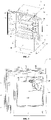
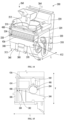
- ice making assembly 200 may include a housing 310 that defines a receiving chamber 350 which is in fluid communication with the inlet air duct 224, and a removable mold assembly 400 which is insertable into the receiving chamber 350.
- the housing 310 may include a first side wall 320 and a second side wall 330 opposite the first side wall 320.
- the first and second side walls 320, 330 may extend from a front 230 of the ice making assembly 200 toward a rear 228 of the ice making assembly 200 (e.g., in the lateral direction L).
- a first forward tab 324 may protrude from a front face 322 of the first side wall 320 in a forward direction (e.g., in the lateral direction L).
- a second forward tab 334 may protrude from a front face 332 of the second side wall 330 in the forward direction (e.g., in the lateral direction L).
- the first forward tab 324 may be located at about a vertical midpoint of the front face 322 of the first side wall 320.
- the second forward tab 334 may be located at about a vertical midpoint of the front face 332 of the second side wall 330.
- the first and second side walls 320, 330 may be connected to each other by a front wall 340 at a front 230 of the ice making assembly 200 (e.g., opposite the inlet air duct 224).
- the front wall 340 may extend generally in the vertical direction V and the transverse direction T.
- the front wall 340 may be located at or near a bottom 312 of the housing 310.
- the front wall 340 may include one or more guide features or protrusions.
- a first protrusion 360 and a second protrusion 370 may protrude from a front face 342 of the front wall 340.
- the first protrusion 360 and the second protrusion 370 may each extend upward (e.g., in the vertical direction V) from a bottom edge 346 of the front wall 340 and may extend to a predetermined distance up the front face 342 of the front wall 340.
- the first protrusion 360 and the second protrusion 370 may extend an equal distance upward.
- a top surface 362 of the first protrusion 360 and a top surface 372 of the second protrusion 370 may be provided below a top edge of the front wall 340. Further, the first protrusion 360 and the second protrusion 370 may be spaced apart from each other in the transverse direction T.
- the ice making assembly 200 may include one or more retention features for securing the removable mold assembly 400 within the receiving chamber 350.
- the one or more retention features may be guided by the one or more guide features or protrusions provided on the front wall 340.
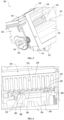
- a latch 380 may be attached to the front wall 340 of the housing 310 and may retain the removable mold assembly 400 within the receiving chamber 350 of the housing 310.
- the latch 380 may be configured to move in the vertical direction V along the front face 342 of the front wall 340.
- the latch 380 may be located between the first protrusion 360 and the second protrusion 370, and may be guided in the vertical direction V by the first protrusion 360 and the second protrusion 370.
- the latch 380 may be biased in the vertical direction V by a spring 384 or elastic member.
- the spring 384 may be provided below the latch 380.
- the spring 384 may be attached to a bottom 312 of the housing 310.
- the spring 384 may be any suitable spring capable of biasing the latch 380 in an upward direction (e.g., the vertical direction V).
- the spring 384 is a leaf spring. It should be appreciated that other retention features are possible and within the scope of the present subject matter, e.g., a swivel latch, a mechanical fastener, a magnet, or the like.
- the removable mold assembly 400 may be generally rectangular in shape.
- the removable mold assembly 400 may include a frame 410, the heat exchanger 220, the resilient or flexible mold 210, and the lifter mechanism 240 including lifter arm 242, lifter projection 246, and roller axle 286.
- the frame 410 may include a mold frame 450 and a partition 460.
- the frame 410 may define a front panel 412, a rear panel 422, a first side panel 424, and a second side panel 428.
- the mold frame 450 may support the heat exchanger 220.
- the heat exchanger 220 is located between the first side panel 424 and the second side panel 428 of the frame 410.
- the heat exchanger 220 may include a mold support surface 432 in contact with the flexible mold 210.
- the mold support surface 432 may include cube recess 222.
- the mold support surface 432 may support the flexible mold 210 and provide a direct contact for heat exchange.
- the partition 460 may include a first plate 434 that generally defines a portion of the front panel 412 of the frame 410.
- the first plate 434 may extend substantially in the vertical direction V and the transverse direction T.
- a rear face 416 of the front panel 412 may contact a front face 426 of the first side panel 424 and a front face 430 of the second side panel 428 of the frame 410.
- a length of the first plate 434 in the transverse direction T may be longer than a distance between the first side panel 424 and the second side panel 428 of the frame 410. In other words, a length l p of the partition 460 in the transverse direction T is longer than a length l m of the mold frame 450 in the transverse direction T.
- the partition 460 may further include a second plate 436 that extends substantially in the lateral direction L and the transverse direction T and is perpendicular to the first plate 434.
- the second plate 436 may extend rearward from a top portion of the first plate 434 (e.g., in the lateral direction L).
- the heat exchanger 220 may be positioned on top of the second plate 436. As previously described, the heat exchanger 220 may define a plurality of heat exchange fins 232 that extend substantially parallel to the flow of cooling air 226 from the inlet air duct 224.
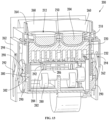
- the rear panel 422 may extend in the transverse direction T and the vertical direction V and may connect the first side panel 424 and the second side panel 428 to each other at a rear of the frame 410.
- the rear panel 422 may be provided at or near a top of the frame 410 to allow the flow of cooling air 226 to pass through the heat exchange fins 232 of the heat exchanger 220.
- the rear panel 422 may include an alignment feature for aligning the removable mold assembly 400 within the receiving chamber 350.
- the alignment feature may be a rear tab 438 that projects rearward (e.g., in the lateral direction L) from the rear panel 422. It should be appreciated that the alignment feature may have any design capable of guiding the removable mold into the receiving chamber 350.
- the rear tab 438 may be provided at or near a center of the rear panel 422 in the transverse direction T.
- the rear tab 438 may be provided at or near a center of the rear panel 422 in the vertical direction V.
- the rear tab 438 may have a slit 446 formed therein at a center thereof.
- the slit 446 extends from a rear edge 440 of the rear tab 438 in the lateral direction L toward the rear panel 422.
- the rear tab 438 is formed as a pair of rear tabs 438 spaced apart in the transverse direction T to form a gap between the pair of rear tabs 438.
- the rear tabs 438 are parallel to each other in the transverse direction T.
- the flexible mold 210 may include a mold bottom 214 and a mold side 216. At least a portion of the mold bottom 214 may contact the mold support surface 432. For instance, an outer surface of the mold bottom 214 (e.g., with respect to the mold cavity 212) predominantly rests on the mold support surface 432.
- the mold side 216 may extend in the vertical direction V from the mold bottom 214. In one embodiment, the mold side 216 is cylindrical. In another embodiment, the mold side 216 comprises a plurality of mold sides 216 that form a closed cross-section in the lateral direction L and transverse direction T. In one example, the plurality of mold sides 216 comprises four mold sides 216 forming a square cross-section. As such, the mold bottom 214 and the mold side 216 may form the mold cavity 212. Further, any suitable number of mold sides 216 may be used to form various shapes of the mold cavity 212.
- the mold bottom 214 may include a stress relief feature 218.
- the stress relief feature 218 may be formed at or near a center of the mold bottom 214.
- the stress relief feature 218 is an inverted cup formed into the mold bottom 214.
- a center portion of the mold bottom 214 may be raised in the vertical direction V with respect to the surrounding portion of the mold bottom 214.
- the stress relief feature 218 may resemble a dome shape at or near the center of the mold bottom 214.
- the stress relief feature 218 may have any suitable shape such that the center portion of the mold bottom 214 is raised in the vertical direction V with respect to the surrounding portion of the mold bottom 214.
- the lifter projection 246 contacts the stress relief feature 218.
- a top of the lifter projection 246 resembles a dome shape that is complementary to a shape of the stress relief feature 218.
- the top of the lifter projection 246 is planar with respect to the lateral direction L and the transverse direction T.
- a plane of the top surface of the lifter projection 246 is perpendicular to the vertical direction V.
- the stress relief feature may form a gap or pocket between the mold bottom 214 and the top surface of the lifter projection 246 at the center of the stress relief feature 218.
- the mold bottom 214 may deform in the lateral direction L and the transverse direction T to spread across the top surface of the lifter projection 246 (e.g., the gap or pocket may collapse). Therefore, stress on the flexible mold 210 may be reduced, in turn reducing material fatigue and failure and prolonging a life of flexible mold 210.
- the air duct 224 may be provided at a rear of the housing 310 (e.g., in the lateral direction L).
- the air duct 224 may define a first outlet 470 and a second outlet 472.
- the first outlet 470 may communicate with the heat exchanger 220 and allow cooling air to pass between the heat exchange fins 232 of heat exchanger 220.
- the second outlet 472 may be provided above the first outlet 470 in the vertical direction V and may communicate with the flexible mold 210. Cooling air 226 may thus flow from the second outlet 472 over the flexible mold 210 to flash-cool liquid stored in mold cavities 212.
- the first outlet 470 and the second outlet 472 may be partitioned by a first surface 474.
- the first surface 474 may include a curved portion 476 and a flat portion 478.
- the flat portion 478 may extend in the lateral direction L and the transverse direction T.
- the curved portion 476 may curve upward (e.g., in the vertical direction V) from the flat portion 478 and may have the second outlet 472 formed therein.
- the air duct 224 may include a guide feature or features for guiding or securing the removable mold within the receiving chamber 350.
- the guide feature may be complimentary to the alignment feature provided on the rear panel 422, such that the alignment feature and the guide feature mechanically engage with each other.
- the guide feature is a T-shaped rail 480 extending along a horizontal direction (e.g., in the lateral direction L).
- the T-shaped rail 480 may be provided at or near a center of the first surface 474 of the air duct 224 in the transverse direction T.
- a base 482 of the T-shaped rail 480 may protrude in the vertical direction V from the flat portion 478 of the first surface 474.
- a pair of arms 484 may protrude in the transverse direction T from a top of the base 482.
- the rear tab 438 may be accepted between the pair of arms 484 and the flat portion 478 of the first surface 474 when the mold assembly 400 is inserted into the receiving cavity.
- the base 482 of the T-shaped rail 480 may be accepted into the gap formed between the pair of rear tabs 438.
- the mold assembly 400 may be removably accommodated within the receiving chamber 350 of the housing 310.
- the latch 380 may be displaced downward (e.g., in the vertical direction V).
- the mold assembly 400 may be fully inserted such that the rear face 416 of the front panel 412 contacts the front face 322 of the first side wall 320 and the front face 332 of the second side wall 330.
- the latch 380 may be biased upward (e.g., in the vertical direction) until a rear surface 382 of the latch 380 contacts a front face 414 of the front panel 412 of the mold assembly 400. In this manner, the mold assembly 400 is secured within the receiving chamber 350 of the housing 310 to facilitate an ice making operation.
- FIG. 20 illustrates an example of when the mold assembly 400 is fully inserted into the receiving chamber 350.
- a bottom face 420 of the front panel 412 may contact a top surface 362 of the first protrusion 360 and a top surface 372 of the second protrusion 370.
- a top face 418 of the front panel 412 may contact a bottom surface 326 of the first forward tab 324 and a bottom surface 336 of the second forward tab 334.
- the rear tab 438 may be interlocked with the T-shaped rail 480.
- the base 482 of the T-shaped rail 480 may be inserted into the slit 446 formed in the rear tab 438.
- An upper surface 442 of the rear tab 438 may contact a lower surface 486 of the pair of arms 484 of the T-shaped rail 480.
- a bottom surface 444 of the rear tab 438 may contact the flat portion 478 of the first surface 474.
- the cam shaft 284 may be provided within the housing 310.
- a bearing 488 may be attached to the housing 310 and may support the cam shaft 284 within the housing 310.
- the bearing 488 may be attached to a rear face 344 of the front wall 340 and extend rearward (e.g., in the lateral direction L).
- the bearing 488 may form an aperture 490 through which the cam shaft 284 passes.
- the aperture 490 may be opened in the transverse direction T.
- the cam shaft 284 may be secured within the housing 310.
- the flexible mold 210 may include one or more mold cavities 212.
- the one or more mold cavities 212 may be predominantly circular in shape and may have a rounded bottom surface in contact with the mold support surface 432, as seen in FIG. 19 .
- the one or more mold cavities 212 may be predominantly square in shape and may have a flat bottom surface in contact with the mold support surface 432, as seen in FIG. 22 . It should be appreciated that any number of molds having any viable three-dimensional shaped mold cavities 212 may be provided. In this manner, a user may remove a first removable mold assembly 400 having a mold cavity 212 with a first shape and insert a second removable mold assembly 400 having a mold cavity 212 with a second shape. Thus, a different shape of ice may be produced according to a desire of the user.
- the lifter mechanism 240 may be connected to the housing 310 as opposed to the mold assembly 400.
- the lifter arm 242, lifter projection 246, and roller axle 286 may be separated from the removable mold assembly 400 and provided within the housing 310.
- One or more grooves may be formed in the heat exchanger 220 through which the lifter arm 242 passes when the mold assembly 400 is inserted into the receiving chamber 350 of the housing 310.
- a removable mold consisting of a flexible rubber mold, heat exchanger, frame, lifter assembly, and partition is removed from the icemaker by depressing a latch. The removable mold is then removed by pulling out on the removable mold. To change the ice shape, a new mold with a different rubber mold cavity 212 shape is inserted into the icemaker.
- the heat exchanger may be machined to define a different mold cavity or shape for receiving a flexible rubber mold. The spring pushes the latch back up locking the module into operating position. Retention features on the module prevent it from moving while the icemaker is operational.
Landscapes
- Engineering & Computer Science (AREA)
- Physics & Mathematics (AREA)
- Mechanical Engineering (AREA)
- Thermal Sciences (AREA)
- General Engineering & Computer Science (AREA)
- Production, Working, Storing, Or Distribution Of Ice (AREA)
- Moulds For Moulding Plastics Or The Like (AREA)
Abstract
Description
- The present subject matter relates generally to refrigerator appliances, and more particularly to ice makers for refrigerator appliances.
- Refrigerator appliances generally include a cabinet that defines one or more chilled chambers for receipt of food articles for storage. Typically, one or more doors are rotatably hinged to the cabinet to permit selective access to food items stored in the chilled chamber. Further, refrigerator appliances commonly include ice making assemblies mounted within an icebox on one of the doors or in a freezer compartment. The ice is stored in a storage bin and is accessible from within the freezer chamber or may be discharged through a dispenser recess defined on a front of the refrigerator door.
- However, conventional ice making assemblies are large, inefficient, experience a variety of performance related issues, and only produce one shape or size of ice cube. For example, conventional twist tray icemakers include a partitioned plastic mold that is physically deformed to break the bond formed between ice and the tray. However, these icemakers require additional room to fully rotate and twist the tray. In addition, the ice cubes are frequently fractured during the twisting process. When this occurs, a portion of the cubes may remain in the tray, thus resulting in overfilling during the next fill process. Further, conventional ice making assemblies only offer one style of ice cube.
- Accordingly, a refrigerator appliance having an ice maker with improved versatility would be desirable. More particularly, an ice making assembly for a refrigerator appliance that is compact, efficient, reliable, and capable of forming more than one type of ice cube would be particularly beneficial.
- Aspects and advantages of the invention will be set forth in part in the following description, or may be obvious from the description, or may be learned through practice of the invention.
- In one exemplary aspect of the present disclosure, an ice maker for a refrigerator appliance is provided. The ice maker may include an ice making assembly defining a receiving chamber and being in fluid communication with an air duct, and a mold assembly removably mounted to the ice making assembly. The mold assembly may include a frame configured for receipt within the receiving chamber of the ice making assembly, a heat exchanger mounted to the frame and defining a mold support surface, and a flexible mold positioned on the mold support surface and being supported by the heat exchanger. The flexible mold may be in thermal communication with the heat exchanger and may define a cavity configured to receive a liquid.
- According to another exemplary embodiment, a refrigerator appliance is provided which may include a cabinet that defines a chilled chamber, a door rotatably mounted to the cabinet and configured to open and close the chilled chamber, an icebox provided in one of the cabinet and the door, and an ice maker provided in the ice making chamber. The ice maker may include an ice making assembly defining a receiving chamber and being in fluid communication with an air duct and a mold assembly insertable into the ice making assembly. The mold assembly may include a frame configured for receipt in the receiving chamber, a heat exchanger mounted to the frame and defining a mold support surface, and a flexible mold positioned on the mold support surface and being supported by the heat exchanger. The flexible mold may be in thermal communication with the heat exchanger and may define a cavity configured to receive a liquid.
- According to still another exemplary embodiment, a mold assembly configured to be inserted into an ice maker is provided. The mold assembly may include a frame, a heat exchanger attached to the frame and defining a mold support surface, a flexible mold in thermal communication with the mold support surface, the flexible mold defining a cavity configured to receive a liquid, at least one lifter configured to contact and deform the flexible mold; and a partition attached to the frame.
- These and other features, aspects and advantages of the present invention will become better understood with reference to the following description and appended claims. The accompanying drawings, which are incorporated in and constitute a part of this specification, illustrate embodiments of the invention and, together with the description, serve to explain the principles of the invention.
- A full and enabling disclosure of the present invention, including the best mode thereof, directed to one of ordinary skill in the art, is set forth in the specification, which makes reference to the appended figures.
-
FIG. 1 provides a perspective view of a refrigerator appliance according to an exemplary embodiment of the present subject matter. -
FIG. 2 provides a perspective view of the exemplary refrigerator appliance ofFIG. 1 , with the doors of the fresh food chamber shown in an open position. -
FIG. 3 provides a perspective view of an icebox and ice making assembly for use with the exemplary refrigerator appliance ofFIG. 1 according to an exemplary embodiment of the present subject matter. -
FIG. 4 provides a perspective view of the exemplary ice making assembly ofFIG. 3 according to an exemplary embodiment of the present subject matter. -
FIG. 5 provides another perspective view of the exemplary ice making assembly ofFIG. 3 according to an exemplary embodiment of the present subject matter. -
FIG. 6 provides another perspective view of the exemplary ice making assembly ofFIG. 3 according to an exemplary embodiment of the present subject matter. -
FIG. 7 provides a side view of the exemplary ice making assembly ofFIG. 3 according to an exemplary embodiment of the present subject matter. -
FIG. 8 provides a partial side view of a drive mechanism, a lifter assembly, and a sweep assembly of the exemplary ice making assembly ofFIG. 3 , with the lifter assembly in a lowered position and the sweep assembly in the retracted position. -
FIG. 9 provides a partial side view of the drive mechanism, the lifter assembly, and the sweep assembly ofFIG. 8 , with the lifter mechanism in the raised position. -
FIG. 10 provides a side view of the drive mechanism, the lifter assembly, and the sweep assembly ofFIG. 8 . -
FIG. 11 provides another side view of the drive mechanism, the lifter assembly, and the sweep assembly ofFIG. 8 , with the sweep assembly in the extended position. -
FIG. 12 provides a partial side view of the drive mechanism, the lifter assembly, and the sweep assembly ofFIG. 8 , with the lifter mechanism in the raised position and the sweep assembly in the extended position. -
FIG. 13 provides another perspective view of the exemplary ice making assembly ofFIG. 3 according to an exemplary embodiment of the present subject matter. -
FIG. 14 provides another perspective view of an ice making assembly including a housing and a mold assembly according to an exemplary embodiment. -
FIG. 15 provides a partial side view of a latch of the housing and the example mold assembly ofFIG. 14 in an inserted position. -
FIG. 16 provides a partial perspective view of the exemplary ice making assembly ofFIG. 14 , the latch in a retracted position. -
FIG. 17 provides a perspective view of the exemplary ice making assembly ofFIG. 14 with the mold assembly removed from the housing. -
FIG. 18 provides a rear view of the mold assembly ofFIG. 14 removed from the housing. -
FIG. 19 provides a partial perspective view of the mold assembly ofFIG. 14 removed from the housing. -
FIG. 20 provides a partial perspective view of the exemplary ice making assembly ofFIG. 14 with the sweep assembly removed. -
FIG. 21 provides a partial perspective view of the exemplary ice making assembly ofFIG. 14 with the sweep assembly and the mold assembly removed. -
FIG. 22 provides a perspective view of the exemplary ice making assembly ofFIG. 14 with an alternate mold assembly in a removed position. - Reference now will be made in detail to embodiments of the invention, one or more examples of which are illustrated in the drawings. Each example is provided by way of explanation of the invention, not limitation of the invention. In fact, it will be apparent to those skilled in the art that various modifications and variations can be made in the present invention without departing from the scope of the invention. For instance, features illustrated or described as part of one embodiment can be used with another embodiment to yield a still further embodiment. Thus, it is intended that the present invention covers such modifications and variations as come within the scope of the appended claims and their equivalents.
-
FIG. 1 provides a perspective view of arefrigerator appliance 100 according to an exemplary embodiment of the present subject matter.Refrigerator appliance 100 includes acabinet 102 that extends between atop 104 and abottom 106 along a vertical direction V, between afirst side 108 and asecond side 110 along a lateral direction L, and between afront side 112 and arear side 114 along a transverse direction T. Each of the vertical direction V, lateral direction L, and transverse direction T are mutually perpendicular to one another. -
Cabinet 102 defines chilled chambers for receipt of food items for storage. In particular,cabinet 102 definesfresh food chamber 122 positioned at oradjacent top 104 ofcabinet 102 and afreezer chamber 124 arranged at oradjacent bottom 106 ofcabinet 102. As such,refrigerator appliance 100 is generally referred to as a bottom mount refrigerator. It is recognized, however, that the benefits of the present disclosure apply to other types and styles of refrigerator appliances such as, e.g., a top mount refrigerator appliance, a side-by-side style refrigerator appliance, or a single door refrigerator appliance. Consequently, the description set forth herein is for illustrative purposes only and is not intended to be limiting in any aspect to any particular refrigerator chamber configuration. -
Refrigerator doors 128 are rotatably hinged to an edge ofcabinet 102 for selectively accessingfresh food chamber 122. In addition, afreezer door 130 is arranged belowrefrigerator doors 128 for selectively accessingfreezer chamber 124.Freezer door 130 is coupled to a freezer drawer (not shown) slidably mounted withinfreezer chamber 124.Refrigerator doors 128 andfreezer door 130 are shown in the closed configuration inFIG. 1 . One skilled in the art will appreciate that other chamber and door configurations are possible and within the scope of the present invention. -
FIG. 2 provides a perspective view ofrefrigerator appliance 100 shown withrefrigerator doors 128 in the open position. As shown inFIG. 2 , various storage components are mounted withinfresh food chamber 122 to facilitate storage of food items therein as will be understood by those skilled in the art. In particular, the storage components may includebins 134 andshelves 136. Each of these storage components are configured for receipt of food items (e.g., beverages and/or solid food items) and may assist with organizing such food items. As illustrated,bins 134 may be mounted onrefrigerator doors 128 or may slide into a receiving space infresh food chamber 122. It should be appreciated that the illustrated storage components are used only for the purpose of explanation and that other storage components may be used and may have different sizes, shapes, and configurations. - Referring now generally to
FIG. 1 , a dispensingassembly 140 will be described according to exemplary embodiments of the present subject matter.Dispensing assembly 140 is generally configured for dispensing liquid water and/or ice. Although anexemplary dispensing assembly 140 is illustrated and described herein, it should be appreciated that variations and modifications may be made to dispensingassembly 140 while remaining within the present subject matter. -
Dispensing assembly 140 and its various components may be positioned at least in part within adispenser recess 142 defined on one ofrefrigerator doors 128. In this regard,dispenser recess 142 is defined on afront side 112 ofrefrigerator appliance 100 such that a user may operate dispensingassembly 140 without openingrefrigerator door 128. In addition,dispenser recess 142 is positioned at a predetermined elevation convenient for a user to access ice and enabling the user to access ice without the need to bend-over. In the exemplary embodiment,dispenser recess 142 is positioned at a level that approximates the chest level of a user. -
Dispensing assembly 140 includes anice dispenser 144 including a dischargingoutlet 146 for discharging ice from dispensingassembly 140. Anactuating mechanism 148, shown as a paddle, is mounted below dischargingoutlet 146 for operating ice orwater dispenser 144. In alternative exemplary embodiments, any suitable actuating mechanism may be used to operateice dispenser 144. For example,ice dispenser 144 can include a sensor (such as an ultrasonic sensor) or a button rather than the paddle. Dischargingoutlet 146 andactuating mechanism 148 are an external part ofice dispenser 144 and are mounted indispenser recess 142. - By contrast, inside
refrigerator appliance 100,refrigerator door 128 may define an icebox 150 (FIGS. 2 and 3 ) housing an icemaker and anice storage bin 152 that are configured to supply ice todispenser recess 142. In this regard, for example,icebox 150 may define anice making chamber 154 for housing an ice making assembly, a storage mechanism, and a dispensing mechanism. - A
control panel 160 is provided for controlling the mode of operation. For example,control panel 160 includes one ormore selector inputs 162, such as knobs, buttons, touchscreen interfaces, etc., such as a water dispensing button and an ice-dispensing button, for selecting a desired mode of operation such as crushed or non-crushed ice. In addition,inputs 162 may be used to specify a fill volume or method of operating dispensingassembly 140. In this regard,inputs 162 may be in communication with a processing device orcontroller 164. Signals generated incontroller 164 operaterefrigerator appliance 100 and dispensingassembly 140 in response toselector inputs 162. Additionally, adisplay 166, such as an indicator light or a screen, may be provided oncontrol panel 160.Display 166 may be in communication withcontroller 164 and may display information in response to signals fromcontroller 164. - As used herein, "processing device" or "controller" may refer to one or more microprocessors or semiconductor devices and is not restricted necessarily to a single element. The processing device can be programmed to operate
refrigerator appliance 100 and dispensingassembly 140. The processing device may include, or be associated with, one or more memory elements (e.g., non-transitory storage media). In some such embodiments, the memory elements include electrically erasable, programmable read only memory (EEPROM). Generally, the memory elements can store information accessible processing device, including instructions that can be executed by processing device. Optionally, the instructions can be software or any set of instructions and/or data that when executed by the processing device, cause the processing device to perform operations. - Referring now generally to
FIGS. 3 through 13 , anice making assembly 200 that may be used withrefrigerator appliance 100 will be described according to exemplary embodiments of the present subject matter. As illustrated,ice making assembly 200 is mounted onicebox 150 withinice making chamber 154 and is configured for receiving a flow of water from a water supply spout 202 (see, e.g.,FIG. 3 ). In this manner,ice making assembly 200 is generally configured for freezing the water to formice cubes 204 which may be stored instorage bin 152 and dispensed through dischargingoutlet 146 by dispensingassembly 140. However, it should be appreciated thatice making assembly 200 is described herein only for the purpose of explaining aspects of the present subject matter. Variations and modifications may be made to ice makingassembly 200 while remaining within the scope of the present subject matter. For example,ice making assembly 200 could instead be positioned withinfreezer chamber 124 ofrefrigerator appliance 100 and may have any other suitable configuration. - According to the illustrated embodiment,
ice making assembly 200 includes aresilient mold 210 that defines amold cavity 212. In general,resilient mold 210 is positioned belowwater supply spout 202 for receiving the gravity-assisted flow of water fromwater supply spout 202.Resilient mold 210 may be constructed from any suitably resilient material that may be deformed to releaseice cubes 204 after formation. For example, according to the illustrated embodiment,resilient mold 210 is formed from silicone or another suitable hydrophobic, food-grade, and resilient material. - According to the illustrated embodiment,
resilient mold 210 defines twomold cavities 212, each being shaped and oriented for forming aseparate ice cube 204. In this regard, for example,water supply spout 202 is configured for refillingresilient mold 210 to a level above a divider wall (not shown) withinresilient mold 210 such that the water overflows into the twomold cavities 212 evenly. According to still other embodiments,water supply spout 202 could have a dedicated discharge nozzle positioned over eachmold cavity 212. Furthermore, it should be appreciated that according to alternative embodiments,ice making assembly 200 may be scaled to form any suitable number ofice cubes 204, e.g., by increasing the number ofmold cavities 212 defined byresilient mold 210. -
Ice making assembly 200 may further include aheat exchanger 220 which is in thermal communication withresilient mold 210 for freezing the water withinmold cavities 212 to form one ormore ice cubes 204. In general,heat exchanger 220 may be formed from any suitable thermally conductive material and may be positioned in direct contact withresilient mold 210. Specifically, according to the illustrated embodiment,heat exchanger 220 is formed from aluminum and is positioned directly belowresilient mold 210. Furthermore,heat exchanger 220 may define acube recess 222 which is configured to receiveresilient mold 210 and shape or define the bottom ofice cubes 204. In this manner,heat exchanger 220 is in direct contact withresilient mold 210 over a large portion of the surface area ofice cubes 204, e.g., to facilitate quick freezing of the water stored withinmold cavities 212. For example,heat exchanger 220 may contactresilient mold 210 over greater than approximately half of the surface area ofice cubes 204. It should be appreciated that as used herein, terms of approximation, such as "approximately," "substantially," or "about," refer to being within a ten percent margin of error. - In addition,
ice making assembly 200 may comprise aninlet air duct 224 that is positionedadjacent heat exchanger 220 and is fluidly coupled with a cool air supply (e.g., illustrated as a flow of cooling air 226). According to the illustrated embodiment,inlet air duct 224 provides the flow of coolingair 226 from arear end 228 of ice making assembly 200 (e.g., to the right along the lateral direction L as shown inFIG. 8 ) throughheat exchanger 220 toward afront end 230 of ice making assembly 200 (e.g., to the left along the lateral direction L as shown inFIG. 8 , i.e., the side whereice cubes 204 are discharged into storage bin 152). - As shown,
inlet air duct 224 generally receives the flow of coolingair 226 from a sealed system ofrefrigerator appliance 100 and directs it over and/throughheat exchanger 220 tocool heat exchanger 220. More specifically, according to the illustrated embodiment,heat exchanger 220 defines a plurality ofheat exchange fins 232 that extend substantially parallel to the flow of coolingair 226. In this regard,heat exchange fins 232 extend down from a top ofheat exchanger 220 along a plane defined by the vertical direction V in the lateral direction L (e.g., whenice making assembly 200 is installed in refrigerator appliance 100). - As best shown in
FIGS. 8 and9 ,ice making assembly 200 further includes alifter mechanism 240 that is positioned belowresilient mold 210 and is generally configured for facilitating the ejection ofice cubes 204 frommold cavities 212. In this regard,lifter mechanism 240 is movable between a lowered position (e.g., as shown inFIG. 8 ) and a raised position (e.g., as shown inFIG. 9 ). Specifically,lifter mechanism 240 includes alifter arm 242 that extends substantially along the vertical direction V and passes through alifter channel 244 defined withinheat exchanger 220. In this manner,lifter channel 244 may guidelifter mechanism 240 as it slides along the vertical direction V. - In addition,
lifter mechanism 240 comprises alifter projection 246 that extends from a top oflifter arm 242 towards arear end 228 ofice making assembly 200. As illustrated,lifter projection 246 generally defines the profile of the bottom ofice cubes 204 and is positioned flush within alifter recess 248 defined byheat exchanger 220 whenlifter mechanism 240 is in the lowered position. In this manner,heat exchanger 220 andlifter projection 246 define a smooth bottom surface ofice cubes 204. More specifically, according to the illustrated embodiment,lifter projection 246 generally curves down and away fromlifter arm 242 to define a smooth divot on a bottom ofice cubes 204. - Referring now specifically to
FIG. 6 ,heat exchanger 220 may further define a hole for receiving atemperature sensor 250 which is used to determine whenice cubes 204 have been formed such that an ejection process may be performed. In this regard, for example,temperature sensor 250 may be in operative communication withcontroller 164 which may monitor the temperature ofheat exchanger 220 and the time water has been inmold cavities 212 to predict whenice cubes 204 have been fully frozen. As used herein, "temperature sensor" may refer to any suitable type of temperature sensor. For example, the temperature sensors may be thermocouples, thermistors, or resistance temperature detectors. In addition, although exemplary positioning of asingle temperature sensor 250 is illustrated herein, it should be appreciated thatice making assembly 200 may include any other suitable number, type, and position of temperature sensors according to alternative embodiments. - Referring now specifically to
FIGS. 4 and7-13 ,ice making assembly 200 further includes asweep assembly 260 which is positioned overresilient mold 210 is generally configured for pushingice cubes 204 out ofmold cavities 212 and intostorage bin 152 after they are formed. Specifically, according to the illustrated embodiment,sweep assembly 260 is movable along the horizontal direction (i.e., as defined by the lateral direction L and the transverse direction T) between a retracted position (e.g., as shown inFIGS. 7 through 10 ) and an extended position (e.g., as shown inFIGS. 11 and12 ). - As described in detail below,
sweep assembly 260 remains in the retracted position while water is added toresilient mold 210, throughout the entire freezing process, and aslifter mechanism 240 is moved towards the raised position. Afterice cubes 204 are in the raised position,sweep assembly 260 moves horizontally from the retracted to the extended position, i.e., towardfront end 230 ofice making assembly 200. In this manner, sweep assembly pushesice cubes 204 off oflifter mechanism 240, out ofresilient mold 210, and over a top ofheat exchanger 220 where they may fall intostorage bin 152. - Notably, dispensing
ice cubes 204 from the top ofice making assembly 200 permits ataller storage bin 152, and thus a larger ice storage capacity relative to ice making machines that dispense ice from a bottom of the icemaker. According to the illustrated embodiment,water supply spout 202 is positioned aboveresilient mold 210 for providing the flow of water intoresilient mold 210. In addition,water supply spout 202 is positioned abovesweep assembly 260 such thatsweep assembly 260 may move between the retracted position and an extended position without contactingwater supply spout 202. According to alternative embodiments,water supply spout 202 may be coupled to mechanical actuator which lowerswater supply spout 202 close toresilient mold 210 whilesweep assembly 260 is in the retracted position. In this manner, the overall height or profile ofice making assembly 200 may be further reduced, thereby maximizing ice storage capacity and minimizing wasted space. - According to the illustrated embodiment,
sweep assembly 260 generally includes vertically extendingside arms 262 that are used to drive a raisedframe 264 that is positioned over top ofresilient mold 210. Specifically, raisedframe 264 extends aroundresilient mold 210 prevents splashing of water withinresilient mold 210. This is particularly important whenice making assembly 200 is mounted onrefrigerator door 128 because movement ofrefrigerator door 128 may cause sloshing of water withinmold cavities 212. - Raised
frame 264 is also designed to facilitate the proper ejection ofice cubes 204. Specifically, according to the illustrated embodiment,sweep assembly 260 defines aforward flange 266 that extends overmold cavities 212 along the vertical direction V proximatefront end 230 ofice making assembly 200 whensweep assembly 260 is in the retracted position. In this manner, aslifter mechanism 240 is moved towards the raised position, a front end ofice cubes 204 contactsforward flange 266, such that lifter mechanism 240 (e.g., lifter projection 246) andforward flange 266cause ice cube 204 to rotate (e.g., counterclockwise as shown inFIG. 9 ). It should be appreciated that according to alternative embodiments, raisedframe 264 may have an open end nearfront end 230 ofice making assembly 200. In this regard,forward flange 266 may not be needed to facilitate the rotation and/or discharge ofice cubes 204. - In addition, as best shown in
FIGS. 8-9 and12 ,sweep assembly 260 may further define an angled pushingsurface 268 proximaterear end 228 ofice making assembly 200. In general, angled pushingsurface 268 is configured for engagingice cubes 204 while they are pivoted upward and assweep assembly 260 is moving toward the extended position to further rotateice cubes 204. Specifically, angled pushing surface may extend at anangle 270 relative to the vertical direction V. According to the illustrated embodiment,angle 270 is less than about 10 degrees, though any other suitable angle for urging ice cubes to rotate 180 degrees may be used according to alternative embodiments. - Referring again generally to
FIGS. 4 through 12 ,ice making assembly 200 may include adrive mechanism 276 which is operably coupled to bothlifter mechanism 240 and sweep assembly 260 to selectively raiselifter mechanism 240 and slidesweep assembly 260 to dischargeice cubes 204 during operation. Specifically, according to the illustrated embodiment,drive mechanism 276 comprises adrive motor 278. As used herein, "motor" may refer to any suitable drive motor and/or transmission assembly for rotating a system component. For example, motor 178 may be a brushless DC electric motor, a stepper motor, or any other suitable type or configuration of motor. Alternatively, for example, motor 178 may be an AC motor, an induction motor, a permanent magnet synchronous motor, or any other suitable type of AC motor. In addition, motor 178 may include any suitable transmission assemblies, clutch mechanisms, or other components. - As best illustrated in
FIGS. 8 and9 , motor 178 may be mechanically coupled to arotating cam 280.Lifter mechanism 240, or more specificallylifter arm 242, may ride againstrotating cam 280 such that the profile ofrotating cam 280 causeslifter mechanism 240 move between the lowered position and the raised position asmotor 278 rotatesrotating cam 280. In addition, according to an exemplary embodiment,lifter mechanism 240 may include aroller 282 mounted to the lower end oflifter arm 242 for providing a low friction interface betweenlifter mechanism 240 androtating cam 280. - More specifically, as best shown in
FIGS. 4 and6 ,ice making assembly 200 may include a plurality oflifter mechanisms 240, each of thelifter mechanisms 240 being positioned below one of theice cubes 204 withinresilient mold 210 or being configured to raise a separate portion ofresilient mold 210. In such an embodiment, rotatingcams 280 are mounted on acam shaft 284 which is mechanically coupled withmotor 278. Asmotor 278 rotatescam shaft 284, rotatingcams 280 may simultaneously movelifter arms 242 along the vertical direction V. In this manner, each of the plurality ofrotating cams 280 may be configured for driving a respective onelifter mechanism 240. In addition, as illustrated inFIG. 6 , aroller axle 286 may extend betweenrollers 282 ofadjacent lifter mechanisms 240 to maintain a proper distance betweenadjacent rollers 282 and to keep them engaged on top of rotatingcams 280. - Referring still generally to
FIGS. 4 through 13 ,drive mechanism 276 may further include ayoke wheel 290 which is mechanically coupled tomotor 278 for drivingsweep assembly 260. Specifically,yoke wheel 290 may rotate along withcam shaft 284 and may include adrive pin 292 positioned at a radially outer portion ofyoke wheel 290 and extending substantially parallel to an axis of rotation of motor 278 (e.g., an axial direction). In addition,side arms 262 ofsweep assembly 260 may define adrive slot 294 which is configured to receivedrive pin 292 during operation. Although asingle yoke wheel 290 is described and illustrated herein, it should be appreciated that bothside arms 262 may includeyoke wheel 290 and driveslot 294 mechanisms. - Notably, the geometry of each
drive slot 294 is defined such thatdrive pin 292 moves sweep assembly 260 along the horizontal direction whendrive pin 292 reaches anend 296 ofdrive slot 294. Notably, according to an exemplary embodiment, this occurs whenlifter mechanism 240 is in the raised position. In order to providecontroller 164 with knowledge of the position of yoke wheel 290 (and drivemechanism 276 more generally),ice making assembly 200 may include aposition sensor 298 for determining a zero position ofyoke wheel 290. - For example, referring briefly to
FIG. 13 , according to the illustrated embodiment,position sensor 298 includes amagnet 300 positioned onyoke wheel 290 and a hall-effect sensor 302 mounted at a fixed position onice making assembly 200. Asyoke wheel 290 is rotated toward a predetermined position, hall-effect sensor 302 can detect the proximity ofmagnet 300 andcontroller 164 may determine thatyoke wheel 290 is in the zero position (or some other known position). Alternatively, any other suitable sensors or methods of detecting the position ofyoke wheel 290 ordrive mechanism 276 may be used. For example, motion sensors, camera systems, optical sensors, acoustic sensors, or simple mechanical contact switches may be used according to alternative embodiments. - According to an exemplary embodiment the present subject matter,
motor 278 may begin to rotate afterice cubes 204 are completely frozen and ready for harvest. In this regard,motor 278 rotates rotating cam 280 (and/or cam shaft 284) approximately 90 degrees to movelifter mechanism 240 from the lowered position to the raised position. In this manner,lifter projection 246 pushesresilient mold 210 upward, thereby deformingresilient mold 210 and releasingice cubes 204.Ice cubes 204 continue to be pushed upward until a front edge ofice cubes 204 contacts forward flange 266 such thatlifter projection 246 rotates a rear end ofice cubes 204 upward. - Notably, as best shown in
FIG. 7 ,yoke wheel 290 rotates withcam shaft 284 such thatdrive pin 292 rotates withindrive slot 294 without movingsweep assembly 260 untilyoke wheel 290 reaches the 90° position (e.g., as shown inFIG. 10 ). Thus, asmotor 278 rotates past 90 degrees,lifter mechanism 240 remains in the raised position whilesweep assembly 260 moves towards the extended position. In this manner, angled pushingsurface 268 engages the raised end ofice cubes 204 to push them out ofresilient mold 210 and rotatesice cubes 204 approximately 180 degrees before dropping them intostorage bin 152. - When
motor 278 reaches 180 degrees rotation,sweep assembly 260 is in the fully extended position andice cubes 204 will fall intostorage bin 152 under the force of gravity. Asmotor 278 rotates past 180 degrees,drive pin 292 begins to pullsweep assembly 260 back toward the retracted position, e.g., via engagement withdrive slot 294. Simultaneously, the profile ofrotating cam 280 is configured to begin loweringlifter mechanism 240. Whenmotor 278 is rotated back to the zero position, as indicated for example byposition sensor 298,sweep assembly 260 may be fully retracted,lifter mechanism 240 may be fully lowered, andresilient mold 210 may be ready for a supply fresh water. At this time,water supply spout 202 may provide a flow of fresh water intomold cavities 212 and the process may be repeated. - Turning now generally to
FIGS. 14 through 22 , an alternate embodiment of theice making assembly 200 will be described. Due to the similarities between embodiments described herein, like reference numerals may be used to refer to the same or similar features. It should also be appreciated that features may be interchangeable between the embodiments described. According to another embodiment,ice making assembly 200 may include ahousing 310 that defines a receivingchamber 350 which is in fluid communication with theinlet air duct 224, and aremovable mold assembly 400 which is insertable into the receivingchamber 350. Thehousing 310 may include afirst side wall 320 and asecond side wall 330 opposite thefirst side wall 320. The first andsecond side walls front 230 of theice making assembly 200 toward a rear 228 of the ice making assembly 200 (e.g., in the lateral direction L). Afirst forward tab 324 may protrude from afront face 322 of thefirst side wall 320 in a forward direction (e.g., in the lateral direction L). Asecond forward tab 334 may protrude from afront face 332 of thesecond side wall 330 in the forward direction (e.g., in the lateral direction L). The firstforward tab 324 may be located at about a vertical midpoint of thefront face 322 of thefirst side wall 320. The secondforward tab 334 may be located at about a vertical midpoint of thefront face 332 of thesecond side wall 330. - The first and
second side walls front wall 340 at afront 230 of the ice making assembly 200 (e.g., opposite the inlet air duct 224). Thefront wall 340 may extend generally in the vertical direction V and the transverse direction T. Thefront wall 340 may be located at or near abottom 312 of thehousing 310. Thefront wall 340 may include one or more guide features or protrusions. For example, according to the illustrated embodiment, afirst protrusion 360 and asecond protrusion 370 may protrude from afront face 342 of thefront wall 340. Thefirst protrusion 360 and thesecond protrusion 370 may each extend upward (e.g., in the vertical direction V) from abottom edge 346 of thefront wall 340 and may extend to a predetermined distance up thefront face 342 of thefront wall 340. Thefirst protrusion 360 and thesecond protrusion 370 may extend an equal distance upward. Atop surface 362 of thefirst protrusion 360 and atop surface 372 of thesecond protrusion 370 may be provided below a top edge of thefront wall 340. Further, thefirst protrusion 360 and thesecond protrusion 370 may be spaced apart from each other in the transverse direction T. - The
ice making assembly 200 may include one or more retention features for securing theremovable mold assembly 400 within the receivingchamber 350. The one or more retention features may be guided by the one or more guide features or protrusions provided on thefront wall 340. For example, alatch 380 may be attached to thefront wall 340 of thehousing 310 and may retain theremovable mold assembly 400 within the receivingchamber 350 of thehousing 310. Thelatch 380 may be configured to move in the vertical direction V along thefront face 342 of thefront wall 340. Thelatch 380 may be located between thefirst protrusion 360 and thesecond protrusion 370, and may be guided in the vertical direction V by thefirst protrusion 360 and thesecond protrusion 370. Thelatch 380 may be biased in the vertical direction V by aspring 384 or elastic member. Thespring 384 may be provided below thelatch 380. Thespring 384 may be attached to abottom 312 of thehousing 310. Thespring 384 may be any suitable spring capable of biasing thelatch 380 in an upward direction (e.g., the vertical direction V). In one example, thespring 384 is a leaf spring. It should be appreciated that other retention features are possible and within the scope of the present subject matter, e.g., a swivel latch, a mechanical fastener, a magnet, or the like. - Referring to
FIGS. 17 through 19 , theremovable mold assembly 400 may be generally rectangular in shape. Theremovable mold assembly 400 may include aframe 410, theheat exchanger 220, the resilient orflexible mold 210, and thelifter mechanism 240 includinglifter arm 242,lifter projection 246, androller axle 286. Theframe 410 may include amold frame 450 and apartition 460. Theframe 410 may define afront panel 412, arear panel 422, afirst side panel 424, and asecond side panel 428. Themold frame 450 may support theheat exchanger 220. In one example, theheat exchanger 220 is located between thefirst side panel 424 and thesecond side panel 428 of theframe 410. Theheat exchanger 220 may include amold support surface 432 in contact with theflexible mold 210. Themold support surface 432 may includecube recess 222. Themold support surface 432 may support theflexible mold 210 and provide a direct contact for heat exchange. - The
partition 460 may include afirst plate 434 that generally defines a portion of thefront panel 412 of theframe 410. Thefirst plate 434 may extend substantially in the vertical direction V and the transverse direction T. Arear face 416 of thefront panel 412 may contact afront face 426 of thefirst side panel 424 and afront face 430 of thesecond side panel 428 of theframe 410. A length of thefirst plate 434 in the transverse direction T may be longer than a distance between thefirst side panel 424 and thesecond side panel 428 of theframe 410. In other words, a length lp of thepartition 460 in the transverse direction T is longer than a length lm of themold frame 450 in the transverse direction T. Thepartition 460 may further include asecond plate 436 that extends substantially in the lateral direction L and the transverse direction T and is perpendicular to thefirst plate 434. Thesecond plate 436 may extend rearward from a top portion of the first plate 434 (e.g., in the lateral direction L). Theheat exchanger 220 may be positioned on top of thesecond plate 436. As previously described, theheat exchanger 220 may define a plurality ofheat exchange fins 232 that extend substantially parallel to the flow of coolingair 226 from theinlet air duct 224. - The
rear panel 422 may extend in the transverse direction T and the vertical direction V and may connect thefirst side panel 424 and thesecond side panel 428 to each other at a rear of theframe 410. Therear panel 422 may be provided at or near a top of theframe 410 to allow the flow of coolingair 226 to pass through theheat exchange fins 232 of theheat exchanger 220. Therear panel 422 may include an alignment feature for aligning theremovable mold assembly 400 within the receivingchamber 350. The alignment feature may be arear tab 438 that projects rearward (e.g., in the lateral direction L) from therear panel 422. It should be appreciated that the alignment feature may have any design capable of guiding the removable mold into the receivingchamber 350. According to an exemplary embodiment, therear tab 438 may be provided at or near a center of therear panel 422 in the transverse direction T. Therear tab 438 may be provided at or near a center of therear panel 422 in the vertical direction V. Therear tab 438 may have aslit 446 formed therein at a center thereof. In one embodiment, theslit 446 extends from arear edge 440 of therear tab 438 in the lateral direction L toward therear panel 422. In another embodiment, therear tab 438 is formed as a pair ofrear tabs 438 spaced apart in the transverse direction T to form a gap between the pair ofrear tabs 438. In this embodiment, therear tabs 438 are parallel to each other in the transverse direction T. - With reference to
FIG. 19 , theflexible mold 210 may include amold bottom 214 and amold side 216. At least a portion of themold bottom 214 may contact themold support surface 432. For instance, an outer surface of the mold bottom 214 (e.g., with respect to the mold cavity 212) predominantly rests on themold support surface 432. Themold side 216 may extend in the vertical direction V from themold bottom 214. In one embodiment, themold side 216 is cylindrical. In another embodiment, themold side 216 comprises a plurality ofmold sides 216 that form a closed cross-section in the lateral direction L and transverse direction T. In one example, the plurality ofmold sides 216 comprises fourmold sides 216 forming a square cross-section. As such, themold bottom 214 and themold side 216 may form themold cavity 212. Further, any suitable number ofmold sides 216 may be used to form various shapes of themold cavity 212. - The
mold bottom 214 may include astress relief feature 218. Thestress relief feature 218 may be formed at or near a center of themold bottom 214. In one example, thestress relief feature 218 is an inverted cup formed into themold bottom 214. In other words, a center portion of themold bottom 214 may be raised in the vertical direction V with respect to the surrounding portion of themold bottom 214. Thestress relief feature 218 may resemble a dome shape at or near the center of themold bottom 214. However, it should be appreciated that thestress relief feature 218 may have any suitable shape such that the center portion of themold bottom 214 is raised in the vertical direction V with respect to the surrounding portion of themold bottom 214. - In one example, the
lifter projection 246 contacts thestress relief feature 218. In other words, a top of thelifter projection 246 resembles a dome shape that is complementary to a shape of thestress relief feature 218. In another embodiment, the top of thelifter projection 246 is planar with respect to the lateral direction L and the transverse direction T. In other words, a plane of the top surface of thelifter projection 246 is perpendicular to the vertical direction V. The stress relief feature may form a gap or pocket between themold bottom 214 and the top surface of thelifter projection 246 at the center of thestress relief feature 218. In other words, only an outer peripheral ring of the top surface of thelifter projection 246 may be in contact with themold bottom 214, and the gap or pocket may be provided within the outer peripheral ring. When thelifter arm 242 moves in the vertical direction V to deform theflexible mold 210, themold bottom 214 may deform in the lateral direction L and the transverse direction T to spread across the top surface of the lifter projection 246 (e.g., the gap or pocket may collapse). Therefore, stress on theflexible mold 210 may be reduced, in turn reducing material fatigue and failure and prolonging a life offlexible mold 210. - The
air duct 224 may be provided at a rear of the housing 310 (e.g., in the lateral direction L). Theair duct 224 may define afirst outlet 470 and asecond outlet 472. Thefirst outlet 470 may communicate with theheat exchanger 220 and allow cooling air to pass between theheat exchange fins 232 ofheat exchanger 220. Thesecond outlet 472 may be provided above thefirst outlet 470 in the vertical direction V and may communicate with theflexible mold 210.Cooling air 226 may thus flow from thesecond outlet 472 over theflexible mold 210 to flash-cool liquid stored inmold cavities 212. Thefirst outlet 470 and thesecond outlet 472 may be partitioned by afirst surface 474. Thefirst surface 474 may include acurved portion 476 and aflat portion 478. Theflat portion 478 may extend in the lateral direction L and the transverse direction T. Thecurved portion 476 may curve upward (e.g., in the vertical direction V) from theflat portion 478 and may have thesecond outlet 472 formed therein. - The
air duct 224 may include a guide feature or features for guiding or securing the removable mold within the receivingchamber 350. The guide feature may be complimentary to the alignment feature provided on therear panel 422, such that the alignment feature and the guide feature mechanically engage with each other. In an exemplary embodiment, the guide feature is a T-shapedrail 480 extending along a horizontal direction (e.g., in the lateral direction L). The T-shapedrail 480 may be provided at or near a center of thefirst surface 474 of theair duct 224 in the transverse directionT. A base 482 of the T-shapedrail 480 may protrude in the vertical direction V from theflat portion 478 of thefirst surface 474. A pair ofarms 484 may protrude in the transverse direction T from a top of thebase 482. Thus, therear tab 438 may be accepted between the pair ofarms 484 and theflat portion 478 of thefirst surface 474 when themold assembly 400 is inserted into the receiving cavity. In another example, thebase 482 of the T-shapedrail 480 may be accepted into the gap formed between the pair ofrear tabs 438. - Referring to
FIGS. 14 through 16 , themold assembly 400 may be removably accommodated within the receivingchamber 350 of thehousing 310. In order to insert themold assembly 400 into the receivingchamber 350, thelatch 380 may be displaced downward (e.g., in the vertical direction V). Themold assembly 400 may be fully inserted such that therear face 416 of thefront panel 412 contacts thefront face 322 of thefirst side wall 320 and thefront face 332 of thesecond side wall 330. When themold assembly 400 is fully inserted into the receivingchamber 350, thelatch 380 may be biased upward (e.g., in the vertical direction) until arear surface 382 of thelatch 380 contacts afront face 414 of thefront panel 412 of themold assembly 400. In this manner, themold assembly 400 is secured within the receivingchamber 350 of thehousing 310 to facilitate an ice making operation. -
FIG. 20 illustrates an example of when themold assembly 400 is fully inserted into the receivingchamber 350. Referring toFIG. 20 , abottom face 420 of thefront panel 412 may contact atop surface 362 of thefirst protrusion 360 and atop surface 372 of thesecond protrusion 370. Atop face 418 of thefront panel 412 may contact abottom surface 326 of the firstforward tab 324 and abottom surface 336 of the secondforward tab 334. Therear tab 438 may be interlocked with the T-shapedrail 480. In other words, thebase 482 of the T-shapedrail 480 may be inserted into theslit 446 formed in therear tab 438. Anupper surface 442 of therear tab 438 may contact alower surface 486 of the pair ofarms 484 of the T-shapedrail 480. Abottom surface 444 of therear tab 438 may contact theflat portion 478 of thefirst surface 474. Thus, a contact between therear tab 438 and the T-shapedrail 480 may prevent a movement of themold assembly 400 in the vertical direction V. - As described earlier, the
cam shaft 284 may be provided within thehousing 310. A bearing 488 may be attached to thehousing 310 and may support thecam shaft 284 within thehousing 310. Thebearing 488 may be attached to arear face 344 of thefront wall 340 and extend rearward (e.g., in the lateral direction L). Thebearing 488 may form anaperture 490 through which thecam shaft 284 passes. Theaperture 490 may be opened in the transverse direction T. Thus, thecam shaft 284 may be secured within thehousing 310. - According to one exemplary embodiment, the
flexible mold 210 may include one ormore mold cavities 212. The one ormore mold cavities 212 may be predominantly circular in shape and may have a rounded bottom surface in contact with themold support surface 432, as seen inFIG. 19 . According to another exemplary embodiment, the one ormore mold cavities 212 may be predominantly square in shape and may have a flat bottom surface in contact with themold support surface 432, as seen inFIG. 22 . It should be appreciated that any number of molds having any viable three-dimensional shapedmold cavities 212 may be provided. In this manner, a user may remove a firstremovable mold assembly 400 having amold cavity 212 with a first shape and insert a secondremovable mold assembly 400 having amold cavity 212 with a second shape. Thus, a different shape of ice may be produced according to a desire of the user. - Further, it should be appreciated that the
lifter mechanism 240 may be connected to thehousing 310 as opposed to themold assembly 400. For instance, thelifter arm 242,lifter projection 246, androller axle 286 may be separated from theremovable mold assembly 400 and provided within thehousing 310. One or more grooves may be formed in theheat exchanger 220 through which thelifter arm 242 passes when themold assembly 400 is inserted into the receivingchamber 350 of thehousing 310. - According to an exemplary embodiment, a removable mold consisting of a flexible rubber mold, heat exchanger, frame, lifter assembly, and partition is removed from the icemaker by depressing a latch. The removable mold is then removed by pulling out on the removable mold. To change the ice shape, a new mold with a different
rubber mold cavity 212 shape is inserted into the icemaker. In addition, or alternatively, the heat exchanger may be machined to define a different mold cavity or shape for receiving a flexible rubber mold. The spring pushes the latch back up locking the module into operating position. Retention features on the module prevent it from moving while the icemaker is operational. - This written description uses examples to disclose the invention, including the best mode, and also to enable any person skilled in the art to practice the invention, including making and using any devices or systems and performing any incorporated methods. The patentable scope of the invention is defined by the claims, and may include other examples that occur to those skilled in the art. Such other examples are intended to be within the scope of the claims if they include structural elements that do not differ from the literal language of the claims, or if they include equivalent structural elements with insubstantial differences from the literal languages of the claims.
Claims (20)
- An ice maker for a refrigerator appliance defining a vertical direction, a lateral direction, and a transverse direction, the ice maker comprising:an ice making assembly defining a receiving chamber in fluid communication with an air duct; anda mold assembly removably mounted to the ice making assembly, the mold assembly comprising:a frame configured for receipt within the receiving chamber of the ice making assembly;a heat exchanger mounted to the frame and defining a mold support surface; anda flexible mold positioned on the mold support surface and being supported by the heat exchanger such that the flexible mold is in thermal communication with the heat exchanger and defines a mold cavity configured to receive a liquid.
- The ice maker of claim 1, wherein the ice making assembly comprises:a housing forming the receiving chamber;a latch attached to a front wall of the housing and being configured to retain the mold assembly within the receiving chamber of the housing; anda spring configured to bias the latch in the vertical direction, and wherein a rear surface of the latch contacts a front face of the frame when the mold assembly is inserted into the receiving chamber of the housing.
- The ice maker of claim 2, wherein the air duct is attached to the housing and includes a T-shaped rail extending along a horizontal direction, and wherein the frame includes a rear tab defining a slit formed therein for receiving the rail.
- The ice maker of claim 2, wherein the housing comprises a first forward tab that extends forward in the lateral direction from a first side wall of the housing and a second forward tab that extends forward in the lateral direction from a second side wall of the housing, and wherein a bottom surface of each of the first and second forward tabs contacts a top face of the frame when the mold assembly is inserted into the receiving chamber of the housing.
- The ice maker of claim 4, wherein the frame comprises a mold frame and a partition,
wherein a length of the partition in the transverse direction is greater than a length of the mold frame in the transverse direction, and wherein the rear surface of the latch contacts a front face of the partition when the mold assembly is inserted into the receiving chamber of the housing. - The ice maker of claim 2, wherein the mold assembly further comprises a plurality of lifters connected by a roller axle and positioned below the flexible mold and the heat exchanger, the plurality of lifters being configured to deform the flexible mold.
- The ice maker of claim 6, further comprising:a cam shaft provided in the housing;at least one cam lobe provided on the cam shaft and configured to drive the plurality of lifters;a yoke wheel provided on the camshaft to rotate coaxially with the camshaft and including a pin radially spaced from a rotation axis of the yoke wheel and protruding axially from the yoke wheel;a motor configured to drive the camshaft; anda bearing attached to the housing and configured to support the camshaft.
- The ice maker of claim 1, wherein a bottom of the flexible mold is dome shaped.
- The ice maker of claim 1, wherein the mold assembly is one of a plurality of distinct mold assemblies each having differently shaped three-dimensional mold cavities, wherein each of the plurality of distinct mold assemblies is configured for receipt within the receiving chamber of the housing.
- A refrigerator defining a vertical direction, a lateral direction, and a transverse direction, the refrigerator comprising:a cabinet that defines a chilled chamber;a door rotatably mounted to the cabinet and configured to open and close the chilled chamber;an icebox provided in one of the cabinet or the door, the icebox defining an ice making chamber; andan ice maker provided in the ice making chamber, wherein the ice maker comprises:an ice making assembly defining a receiving chamber in fluid communication with an air duct; anda mold assembly insertable into the ice making assembly, the mold assembly comprising:a frame configured for receipt in the receiving chamber;a heat exchanger mounted to the frame and defining a mold support surface; anda flexible mold positioned on the mold support surface and being supported by the heat exchanger such that the flexible mold is in thermal communication with the heat exchanger and defines a mold cavity configured to receive a liquid.
- The refrigerator of claim 10, wherein the ice making assembly comprises:a housing forming the receiving chamber;a latch attached to a front wall of the housing and being configured to retain the mold assembly within the receiving chamber of the housing; anda spring configured to bias the latch in the vertical direction, and wherein a rear surface of the latch contacts a front face of the partition when the mold assembly is inserted into the receiving chamber of the housing.
- The refrigerator of claim 11, wherein a bottom of the flexible mold is dome shaped.
- The refrigerator of claim 11, wherein the air duct is attached to the housing and includes a T-shaped rail, and wherein the frame includes a rear tab defining a slit formed therein for receiving the rail.
- The refrigerator of claim 11, wherein the housing comprises a first forward tab that extends forward in the lateral direction from a first side wall of the housing and a second forward tab that extends forward in the lateral direction from a second side wall of the housing, and wherein a bottom surface of each of the first and second forward tabs contacts a top face of the frame when the mold assembly is inserted into the receiving chamber of the housing.
- The refrigerator of claim 14, wherein the frame comprises a mold frame and a partition, and wherein a length of the partition in the transverse direction is greater than a length of the mold frame in the transverse direction.
- The refrigerator of claim 11, wherein the mold assembly further comprises a plurality of lifters connected by a roller axle and positioned below the flexible mold and the heat exchanger, the plurality of lifters being configured to deform the flexible mold.
- The refrigerator of claim 16, further comprising:a camshaft provided in the housing;at least one cam lobe provided on the cam shaft and configured to drive the plurality of lifters;a yoke wheel provided on the camshaft to rotate coaxially with the camshaft and including a pin radially spaced from a rotation axis of the yoke wheel and protruding axially from the yoke wheel;a motor configured to drive the camshaft; anda bearing attached to the housing and configured to support the camshaft.
- The refrigerator of claim 17, further comprising a sweep assembly movably attached to the ice making assembly, wherein the sweep assembly includes a groove in which the pin is accommodated such that as the camshaft is rotated, the sweep assembly oscillates between a retracted position and an extended position.
- A mold assembly configured to be inserted into an ice maker, the mold assembly comprising:a frame;a heat exchanger attached to the frame and defining a mold support surface;a flexible mold in thermal communication with the mold support surface, the flexible mold defining a cavity configured to receive a liquid;at least one lifter configured to contact and deform the flexible mold; anda partition attached to the frame.
- The removable module of claim 19, wherein the at least one lifter comprises a pair of lifters joined by a shaft, and wherein the pair of lifters are provided under the flexible mold and pass vertically through the heat exchanger.
Applications Claiming Priority (2)
| Application Number | Priority Date | Filing Date | Title |
|---|---|---|---|
| US16/846,549 US11486623B2 (en) | 2020-04-13 | 2020-04-13 | Ice making assembly for receiving interchangeable mold assemblies |
| PCT/CN2021/082069 WO2021208672A1 (en) | 2020-04-13 | 2021-03-22 | Ice making assembly for receiving interchangeable mold assembly |
Publications (2)
| Publication Number | Publication Date |
|---|---|
| EP4137762A1 true EP4137762A1 (en) | 2023-02-22 |
| EP4137762A4 EP4137762A4 (en) | 2023-09-13 |
Family
ID=78006572
Family Applications (1)
| Application Number | Title | Priority Date | Filing Date |
|---|---|---|---|
| EP21788383.4A Pending EP4137762A4 (en) | 2020-04-13 | 2021-03-22 | Ice making assembly for receiving interchangeable mold assembly |
Country Status (5)
| Country | Link |
|---|---|
| US (1) | US11486623B2 (en) |
| EP (1) | EP4137762A4 (en) |
| CN (1) | CN115427745B (en) |
| AU (1) | AU2021256018B2 (en) |
| WO (1) | WO2021208672A1 (en) |
Cited By (1)
| Publication number | Priority date | Publication date | Assignee | Title |
|---|---|---|---|---|
| WO2025066379A1 (en) * | 2023-09-26 | 2025-04-03 | Haier Smart Home Co., Ltd. | Sweep assembly for a refrigerator icemaker |
Families Citing this family (10)
| Publication number | Priority date | Publication date | Assignee | Title |
|---|---|---|---|---|
| KR20230008168A (en) * | 2020-05-20 | 2023-01-13 | 일렉트로룩스 홈 프로덕츠 인코퍼레이티드 | Refrigeration appliance ice bin storage |
| TR202018084A2 (en) * | 2020-11-12 | 2022-05-23 | Arcelik As | COOLING DEVICE WITH ICE MAKING SYSTEM |
| US20230221053A1 (en) * | 2022-01-07 | 2023-07-13 | Haier Us Appliance Solutions, Inc. | Multi-cavity ice making assembly |
| US12618599B2 (en) * | 2023-05-16 | 2026-05-05 | Haier Us Appliance Solutions, Inc. | Ice making assembly for a refrigerator appliance |
| US20240410634A1 (en) * | 2023-06-07 | 2024-12-12 | Haier Us Appliance Solutions, Inc. | Ice making assembly with rotating tray |
| KR20250069161A (en) * | 2023-11-10 | 2025-05-19 | 엘지전자 주식회사 | Refrigerator |
| US20250189197A1 (en) * | 2023-12-06 | 2025-06-12 | Haier Us Appliance Solutions, Inc. | Infused ice maker appliance with automatic harvesting |
| US20260049752A1 (en) * | 2024-08-15 | 2026-02-19 | Haier Us Appliance Solutions, Inc. | Appliance ice making assembly |
| WO2026045243A1 (en) * | 2024-08-29 | 2026-03-05 | 起源未来创新科技(重庆)有限公司 | Ice maker with replaceable mold, ice making mold thereof, and stirring mechanism |
| CN118935846B (en) * | 2024-08-29 | 2026-03-20 | 起源未来创新科技(重庆)有限公司 | An ice maker with interchangeable molds |
Family Cites Families (32)
| Publication number | Priority date | Publication date | Assignee | Title |
|---|---|---|---|---|
| US3163018A (en) | 1961-08-02 | 1964-12-29 | Borg Warner | Cube type ice maker having electric heater and cam ejector |
| US3217511A (en) * | 1963-03-26 | 1965-11-16 | Gen Motors Corp | Ice block harvesting arrangement |
| US3850008A (en) | 1972-12-27 | 1974-11-26 | Gen Electric | Ice maker |
| US4261182A (en) | 1978-10-05 | 1981-04-14 | General Electric Company | Automatic icemaker including means for minimizing the supercooling effect |
| US5056321A (en) | 1990-11-20 | 1991-10-15 | Mid-South Industries, Inc. | Half crescent shaped ice piece maker |
| US5502980A (en) * | 1993-09-23 | 1996-04-02 | O. R. Solutions, Inc. | Sterile drape for use in making surgical slush |
| US5809788A (en) * | 1996-03-05 | 1998-09-22 | O.R. Solutions, Inc. | Surgical drape for use in forming and collecting surgical slush |
| JP4257986B2 (en) | 1999-02-25 | 2009-04-30 | 三菱電機株式会社 | Automatic ice making machine |
| US7131280B2 (en) | 2004-10-26 | 2006-11-07 | Whirlpool Corporation | Method for making ice in a compact ice maker |
| US7185508B2 (en) * | 2004-10-26 | 2007-03-06 | Whirlpool Corporation | Refrigerator with compact icemaker |
| KR100611496B1 (en) | 2004-11-30 | 2006-08-09 | 엘지전자 주식회사 | Heat Ejector for Heating Type Ice Maker |
| JP3810427B1 (en) * | 2005-03-17 | 2006-08-16 | シャープ株式会社 | Ice making device and refrigerator equipped with ice making device |
| KR20060107666A (en) | 2005-04-11 | 2006-10-16 | 엘지전자 주식회사 | Ice Maker |
| US8037697B2 (en) | 2008-01-09 | 2011-10-18 | Whirlpool Corporation | Refrigerator with an automatic compact fluid operated icemaker |
| EP2216613A1 (en) * | 2009-02-09 | 2010-08-11 | Dometic Sweden AB | Ice maker and method of producing pieces of ice |
| US9217599B2 (en) * | 2009-02-28 | 2015-12-22 | Electrolux Home Products, Inc. | Water introduction into fresh-food icemaker |
| US8539780B2 (en) | 2010-06-28 | 2013-09-24 | General Electric Company | Method and apparatus for harvesting ice in an ice maker system |
| CN101949625B (en) * | 2010-09-06 | 2012-05-23 | 合肥美的荣事达电冰箱有限公司 | Ice crushing motor mounting device and ice crushing motor unit of ice making equipment, and ice making equipment |
| DE102010040339A1 (en) * | 2010-09-07 | 2012-03-08 | BSH Bosch und Siemens Hausgeräte GmbH | Ice maker with storage facilities for mold shells, as well as mold shell and refrigeration device with such an icemaker |
| US8397532B2 (en) * | 2010-10-18 | 2013-03-19 | General Electric Company | Direct-cooled ice-making assembly and refrigeration appliance incorporating same |
| MX2011004880A (en) * | 2011-05-04 | 2012-11-27 | Mabe Sa De Cv | Ice making device with tank. |
| US9557087B2 (en) * | 2012-12-13 | 2017-01-31 | Whirlpool Corporation | Clear ice making apparatus having an oscillation frequency and angle |
| US9500398B2 (en) * | 2012-12-13 | 2016-11-22 | Whirlpool Corporation | Twist harvest ice geometry |
| US9310115B2 (en) * | 2012-12-13 | 2016-04-12 | Whirlpool Corporation | Layering of low thermal conductive material on metal tray |
| WO2014102111A1 (en) | 2012-12-26 | 2014-07-03 | Arcelik Anonim Sirketi | An ice serving unit comprising an actuation mechanism |
| CN204444074U (en) * | 2015-01-06 | 2015-07-08 | 广州市福立达电器有限公司 | Ice lolly machine |
| US9746229B2 (en) * | 2015-03-06 | 2017-08-29 | Whilpool Corporation | Hybrid twist tray ice maker |
| US20170082338A1 (en) * | 2015-09-18 | 2017-03-23 | Jesse L. Wobrock | Systems and methods for forming shaped ice |
| US20180202699A1 (en) * | 2017-01-19 | 2018-07-19 | Fuji Electric Co., Ltd. | Ice making apparatus |
| US10788252B2 (en) * | 2018-07-19 | 2020-09-29 | Haier Us Appliance Solutions, Inc. | Ice making assembly for a refrigerator appliance |
| EP3862683B1 (en) * | 2018-10-02 | 2025-02-26 | LG Electronics Inc. | Refrigerator |
| CN209569941U (en) * | 2018-12-21 | 2019-11-01 | 合肥美的电冰箱有限公司 | Refrigerator with ice machine |
-
2020
- 2020-04-13 US US16/846,549 patent/US11486623B2/en active Active
-
2021
- 2021-03-22 WO PCT/CN2021/082069 patent/WO2021208672A1/en not_active Ceased
- 2021-03-22 CN CN202180026234.1A patent/CN115427745B/en active Active
- 2021-03-22 EP EP21788383.4A patent/EP4137762A4/en active Pending
- 2021-03-22 AU AU2021256018A patent/AU2021256018B2/en active Active
Cited By (1)
| Publication number | Priority date | Publication date | Assignee | Title |
|---|---|---|---|---|
| WO2025066379A1 (en) * | 2023-09-26 | 2025-04-03 | Haier Smart Home Co., Ltd. | Sweep assembly for a refrigerator icemaker |
Also Published As
| Publication number | Publication date |
|---|---|
| WO2021208672A1 (en) | 2021-10-21 |
| US11486623B2 (en) | 2022-11-01 |
| AU2021256018B2 (en) | 2024-02-29 |
| CN115427745B (en) | 2023-11-07 |
| AU2021256018A1 (en) | 2022-10-20 |
| US20210318051A1 (en) | 2021-10-14 |
| EP4137762A4 (en) | 2023-09-13 |
| CN115427745A (en) | 2022-12-02 |
Similar Documents
| Publication | Publication Date | Title |
|---|---|---|
| AU2021256018B2 (en) | Ice making assembly for receiving interchangeable mold assembly | |
| US10788252B2 (en) | Ice making assembly for a refrigerator appliance | |
| AU2020324207B2 (en) | Ice making assembly of refrigerating appliance | |
| EP2422145B1 (en) | Refrigerator | |
| EP3460361B1 (en) | Ice maker and refrigerator including the same | |
| US20220316782A1 (en) | Appliance ice making assembly | |
| US20240255203A1 (en) | Systems for ice mold assemblies in ice maker appliances | |
| US12429270B2 (en) | Refrigerator appliances and removable ice making assemblies | |
| WO2024251102A9 (en) | Ice making assembly with rotating tray | |
| EP4597007A1 (en) | Ice-making assembly for refrigeration appliance | |
| US12253290B2 (en) | Ice making assembly for a refrigerator appliance | |
| EP3460366B1 (en) | Ice maker | |
| US12618599B2 (en) | Ice making assembly for a refrigerator appliance | |
| US12222149B2 (en) | Refrigerator appliances and ice making assemblies having one or more ice ejection cams | |
| EP3460362B1 (en) | Ice maker and refrigerator including the same | |
| US20240401861A1 (en) | Ice maker appliance with automatic shut off features | |
| WO2025066379A1 (en) | Sweep assembly for a refrigerator icemaker | |
| EP4603770A1 (en) | Refrigerator | |
| KR20220022219A (en) | Refrigerator and method for controlling the same |
Legal Events
| Date | Code | Title | Description |
|---|---|---|---|
| STAA | Information on the status of an ep patent application or granted ep patent |
Free format text: STATUS: THE INTERNATIONAL PUBLICATION HAS BEEN MADE |
|
| PUAI | Public reference made under article 153(3) epc to a published international application that has entered the european phase |
Free format text: ORIGINAL CODE: 0009012 |
|
| STAA | Information on the status of an ep patent application or granted ep patent |
Free format text: STATUS: REQUEST FOR EXAMINATION WAS MADE |
|
| 17P | Request for examination filed |
Effective date: 20220329 |
|
| AK | Designated contracting states |
Kind code of ref document: A1 Designated state(s): AL AT BE BG CH CY CZ DE DK EE ES FI FR GB GR HR HU IE IS IT LI LT LU LV MC MK MT NL NO PL PT RO RS SE SI SK SM TR |
|
| DAV | Request for validation of the european patent (deleted) | ||
| DAX | Request for extension of the european patent (deleted) | ||
| A4 | Supplementary search report drawn up and despatched |
Effective date: 20230811 |
|
| RIC1 | Information provided on ipc code assigned before grant |
Ipc: F25D 11/02 20060101AFI20230807BHEP |
|
| STAA | Information on the status of an ep patent application or granted ep patent |
Free format text: STATUS: EXAMINATION IS IN PROGRESS |
|
| 17Q | First examination report despatched |
Effective date: 20241113 |