EP4137754A1 - Binary refrigeration device - Google Patents
Binary refrigeration device Download PDFInfo
- Publication number
- EP4137754A1 EP4137754A1 EP21816648.6A EP21816648A EP4137754A1 EP 4137754 A1 EP4137754 A1 EP 4137754A1 EP 21816648 A EP21816648 A EP 21816648A EP 4137754 A1 EP4137754 A1 EP 4137754A1
- Authority
- EP
- European Patent Office
- Prior art keywords
- temperature side
- low
- tube
- heat exchanger
- side refrigerant
- Prior art date
- Legal status (The legal status is an assumption and is not a legal conclusion. Google has not performed a legal analysis and makes no representation as to the accuracy of the status listed.)
- Granted
Links
Images


Classifications
-
- F—MECHANICAL ENGINEERING; LIGHTING; HEATING; WEAPONS; BLASTING
- F25—REFRIGERATION OR COOLING; COMBINED HEATING AND REFRIGERATION SYSTEMS; HEAT PUMP SYSTEMS; MANUFACTURE OR STORAGE OF ICE; LIQUEFACTION SOLIDIFICATION OF GASES
- F25B—REFRIGERATION MACHINES, PLANTS OR SYSTEMS; COMBINED HEATING AND REFRIGERATION SYSTEMS; HEAT PUMP SYSTEMS
- F25B7/00—Compression machines, plants or systems, with cascade operation, i.e. with two or more circuits, the heat from the condenser of one circuit being absorbed by the evaporator of the next circuit
-
- F—MECHANICAL ENGINEERING; LIGHTING; HEATING; WEAPONS; BLASTING
- F25—REFRIGERATION OR COOLING; COMBINED HEATING AND REFRIGERATION SYSTEMS; HEAT PUMP SYSTEMS; MANUFACTURE OR STORAGE OF ICE; LIQUEFACTION SOLIDIFICATION OF GASES
- F25B—REFRIGERATION MACHINES, PLANTS OR SYSTEMS; COMBINED HEATING AND REFRIGERATION SYSTEMS; HEAT PUMP SYSTEMS
- F25B39/00—Evaporators; Condensers
-
- F—MECHANICAL ENGINEERING; LIGHTING; HEATING; WEAPONS; BLASTING
- F25—REFRIGERATION OR COOLING; COMBINED HEATING AND REFRIGERATION SYSTEMS; HEAT PUMP SYSTEMS; MANUFACTURE OR STORAGE OF ICE; LIQUEFACTION SOLIDIFICATION OF GASES
- F25B—REFRIGERATION MACHINES, PLANTS OR SYSTEMS; COMBINED HEATING AND REFRIGERATION SYSTEMS; HEAT PUMP SYSTEMS
- F25B6/00—Compression machines, plants or systems, with several condenser circuits
- F25B6/02—Compression machines, plants or systems, with several condenser circuits arranged in parallel
-
- F—MECHANICAL ENGINEERING; LIGHTING; HEATING; WEAPONS; BLASTING
- F28—HEAT EXCHANGE IN GENERAL
- F28D—HEAT-EXCHANGE APPARATUS, NOT PROVIDED FOR IN ANOTHER SUBCLASS, IN WHICH THE HEAT-EXCHANGE MEDIA DO NOT COME INTO DIRECT CONTACT
- F28D7/00—Heat-exchange apparatus having stationary tubular conduit assemblies for both heat-exchange media, the media being in contact with different sides of a conduit wall
- F28D7/02—Heat-exchange apparatus having stationary tubular conduit assemblies for both heat-exchange media, the media being in contact with different sides of a conduit wall the conduits being helically coiled
- F28D7/024—Heat-exchange apparatus having stationary tubular conduit assemblies for both heat-exchange media, the media being in contact with different sides of a conduit wall the conduits being helically coiled the conduits of only one medium being helically coiled tubes, the coils having a cylindrical configuration
-
- F—MECHANICAL ENGINEERING; LIGHTING; HEATING; WEAPONS; BLASTING
- F28—HEAT EXCHANGE IN GENERAL
- F28D—HEAT-EXCHANGE APPARATUS, NOT PROVIDED FOR IN ANOTHER SUBCLASS, IN WHICH THE HEAT-EXCHANGE MEDIA DO NOT COME INTO DIRECT CONTACT
- F28D7/00—Heat-exchange apparatus having stationary tubular conduit assemblies for both heat-exchange media, the media being in contact with different sides of a conduit wall
- F28D7/10—Heat-exchange apparatus having stationary tubular conduit assemblies for both heat-exchange media, the media being in contact with different sides of a conduit wall the conduits being arranged one within the other, e.g. concentrically
- F28D7/106—Heat-exchange apparatus having stationary tubular conduit assemblies for both heat-exchange media, the media being in contact with different sides of a conduit wall the conduits being arranged one within the other, e.g. concentrically consisting of two coaxial conduits or modules of two coaxial conduits
-
- F—MECHANICAL ENGINEERING; LIGHTING; HEATING; WEAPONS; BLASTING
- F28—HEAT EXCHANGE IN GENERAL
- F28D—HEAT-EXCHANGE APPARATUS, NOT PROVIDED FOR IN ANOTHER SUBCLASS, IN WHICH THE HEAT-EXCHANGE MEDIA DO NOT COME INTO DIRECT CONTACT
- F28D9/00—Heat-exchange apparatus having stationary plate-like or laminated conduit assemblies for both heat-exchange media, the media being in contact with different sides of a conduit wall
- F28D9/0031—Heat-exchange apparatus having stationary plate-like or laminated conduit assemblies for both heat-exchange media, the media being in contact with different sides of a conduit wall the conduits for one heat-exchange medium being formed by paired plates touching each other
- F28D9/0037—Heat-exchange apparatus having stationary plate-like or laminated conduit assemblies for both heat-exchange media, the media being in contact with different sides of a conduit wall the conduits for one heat-exchange medium being formed by paired plates touching each other the conduits for the other heat-exchange medium also being formed by paired plates touching each other
-
- F—MECHANICAL ENGINEERING; LIGHTING; HEATING; WEAPONS; BLASTING
- F28—HEAT EXCHANGE IN GENERAL
- F28F—DETAILS OF HEAT-EXCHANGE AND HEAT-TRANSFER APPARATUS, OF GENERAL APPLICATION
- F28F1/00—Tubular elements; Assemblies of tubular elements
- F28F1/02—Tubular elements of cross-section which is non-circular
- F28F1/025—Tubular elements of cross-section which is non-circular with variable shape, e.g. with modified tube ends, with different geometrical features
-
- F—MECHANICAL ENGINEERING; LIGHTING; HEATING; WEAPONS; BLASTING
- F25—REFRIGERATION OR COOLING; COMBINED HEATING AND REFRIGERATION SYSTEMS; HEAT PUMP SYSTEMS; MANUFACTURE OR STORAGE OF ICE; LIQUEFACTION SOLIDIFICATION OF GASES
- F25B—REFRIGERATION MACHINES, PLANTS OR SYSTEMS; COMBINED HEATING AND REFRIGERATION SYSTEMS; HEAT PUMP SYSTEMS
- F25B2400/00—General features or devices for refrigeration machines, plants or systems, combined heating and refrigeration systems or heat-pump systems, i.e. not limited to a particular subgroup of F25B
- F25B2400/05—Compression system with heat exchange between particular parts of the system
- F25B2400/052—Compression system with heat exchange between particular parts of the system between the capillary tube and another part of the refrigeration cycle
-
- F—MECHANICAL ENGINEERING; LIGHTING; HEATING; WEAPONS; BLASTING
- F25—REFRIGERATION OR COOLING; COMBINED HEATING AND REFRIGERATION SYSTEMS; HEAT PUMP SYSTEMS; MANUFACTURE OR STORAGE OF ICE; LIQUEFACTION SOLIDIFICATION OF GASES
- F25B—REFRIGERATION MACHINES, PLANTS OR SYSTEMS; COMBINED HEATING AND REFRIGERATION SYSTEMS; HEAT PUMP SYSTEMS
- F25B2400/00—General features or devices for refrigeration machines, plants or systems, combined heating and refrigeration systems or heat-pump systems, i.e. not limited to a particular subgroup of F25B
- F25B2400/05—Compression system with heat exchange between particular parts of the system
- F25B2400/054—Compression system with heat exchange between particular parts of the system between the suction tube of the compressor and another part of the cycle
-
- F—MECHANICAL ENGINEERING; LIGHTING; HEATING; WEAPONS; BLASTING
- F25—REFRIGERATION OR COOLING; COMBINED HEATING AND REFRIGERATION SYSTEMS; HEAT PUMP SYSTEMS; MANUFACTURE OR STORAGE OF ICE; LIQUEFACTION SOLIDIFICATION OF GASES
- F25B—REFRIGERATION MACHINES, PLANTS OR SYSTEMS; COMBINED HEATING AND REFRIGERATION SYSTEMS; HEAT PUMP SYSTEMS
- F25B2500/00—Problems to be solved
- F25B2500/01—Geometry problems, e.g. for reducing size
-
- F—MECHANICAL ENGINEERING; LIGHTING; HEATING; WEAPONS; BLASTING
- F25—REFRIGERATION OR COOLING; COMBINED HEATING AND REFRIGERATION SYSTEMS; HEAT PUMP SYSTEMS; MANUFACTURE OR STORAGE OF ICE; LIQUEFACTION SOLIDIFICATION OF GASES
- F25B—REFRIGERATION MACHINES, PLANTS OR SYSTEMS; COMBINED HEATING AND REFRIGERATION SYSTEMS; HEAT PUMP SYSTEMS
- F25B40/00—Subcoolers, desuperheaters or superheaters
-
- F—MECHANICAL ENGINEERING; LIGHTING; HEATING; WEAPONS; BLASTING
- F28—HEAT EXCHANGE IN GENERAL
- F28D—HEAT-EXCHANGE APPARATUS, NOT PROVIDED FOR IN ANOTHER SUBCLASS, IN WHICH THE HEAT-EXCHANGE MEDIA DO NOT COME INTO DIRECT CONTACT
- F28D21/00—Heat-exchange apparatus not covered by any of the groups F28D1/00 - F28D20/00
- F28D2021/0019—Other heat exchangers for particular applications; Heat exchange systems not otherwise provided for
- F28D2021/0068—Other heat exchangers for particular applications; Heat exchange systems not otherwise provided for for refrigerant cycles
Definitions
- the present disclosure relates to a binary refrigeration apparatus.
- PTL 1 discloses a binary refrigeration circuit including a cascade capacitor that exchanges heat between a high-temperature side refrigerant flowing through a high-temperature side refrigeration circuit and a low-temperature side refrigerant flowing through a low-temperature side refrigeration circuit.
- the cascade capacitor disclosed in PTL 1 is a plate heat exchanger.
- an object of the present disclosure is to provide a binary refrigeration circuit that can improve the heat exchange efficiency in a plate heat exchanger.
- a binary refrigeration apparatus includes: a low-temperature side refrigeration circuit including a spiral heat exchanger including a main tube and a spiral tube wound around the main tube in a spiral form, the main tube being a tube where a low-temperature side refrigerant that flows into a low-temperature side compressor enters, the spiral tube being a tube where the low-temperature side refrigerant flown out from the low-temperature side compressor enters; and a high-temperature side refrigeration circuit where a high-temperature side refrigerant that exchanges heat with the low-temperature side refrigerant through a plate heat exchanger circulates.
- a binary refrigeration apparatus includes: a low-temperature side refrigeration circuit including a double-tube heat exchanger including a multi-petal tube formed in a tubular shape with a wave shape in a cross section orthogonal to an axis line and an outer tube formed in a tubular shape for housing the multi-petal tube inside, the multi-petal tube being a tube where a low-temperature side refrigerant flown out from a low-temperature side compressor enters, the outer tube being a tube where the low-temperature side refrigerant that flows into the low-temperature side compressor enters between an inner peripheral surface of the outer tube and an outer peripheral surface of the multi-petal tube; and a high-temperature side refrigeration circuit where a high-temperature side refrigerant that exchanges heat with the low-temperature side refrigerant through a plate heat exchanger circulates.
- a low-temperature side refrigeration circuit including a double-tube heat exchanger including a multi-petal tube formed in a tubular shape with a
- the binary refrigeration apparatus can improve the heat exchange efficiency in a plate heat exchanger.
- Binary refrigeration apparatus 1 of a first embodiment of the present disclosure is described below with reference to the drawings.
- Binary refrigeration apparatus 1 is provided in freezer 2 ( FIG. 5 ) such as an ultra-low-temperature freezer where the inner temperature of the storage is -80°C or below, for example.
- binary refrigeration apparatus 1 includes high-temperature side refrigeration circuit 10 and low-temperature side refrigeration circuit 20.
- High-temperature side refrigeration circuit 10 includes high-temperature side compressor 11, high-temperature side condenser 12, high-temperature side dryer 13, high-temperature side decompressor 14, high-temperature side evaporator 15, liquid receiver 16 and high-temperature side heat exchanger 17.
- High-temperature side heat exchanger 17 is composed of a double tube.
- the inner tube of high-temperature side heat exchanger 17 is high-temperature side decompressor 14.
- high-temperature side evaporator 15 makes up plate heat exchanger 30 described later.
- Liquid receiver 16 is formed in a cylindrical shape.
- High-temperature side pipe 18 is an example of "pipe”.
- the high-temperature side refrigerant circulates in the arrow direction illustrated in FIG. 1 . More specifically, the high-temperature side refrigerant returns to high-temperature side compressor 11 after flowing through high-temperature side compressor 11, high-temperature side condenser 12, high-temperature side dryer 13, high-temperature side decompressor 14, high-temperature side evaporator 15, liquid receiver 16 and outer pipe 17a of high-temperature side heat exchanger 17, in this order.
- Low-temperature side refrigeration circuit 20 includes low-temperature side compressor 21, spiral heat exchanger 22, low-temperature side condenser 23, low-temperature side dryer 24, low-temperature side decompressor 25, low-temperature side evaporator 26 and low-temperature side heat exchanger 27.
- Low-temperature side dryer 24 is an example of "dryer”.
- Low-temperature side dryer 24 is formed in a cylindrical shape.
- Spiral heat exchanger 22 includes main tube 22a and spiral tube 22b.
- Main tube 22a is formed in a cylindrical shape through which the low-temperature side refrigerant flows inside. Main tube 22a is disposed such that the axis line direction of main tube 22a is set along the up-down direction.
- Spiral tube 22b is wound around main tube 22a in a spiral form such that the low-temperature side refrigerant flows from the upper side toward the lower side of main tube 22a.
- Spiral tube 22b is formed in a rectangular shape in cross section.
- Low-temperature side heat exchanger 27 is composed of a double tube.
- the inner tube of low-temperature side heat exchanger 27 is low-temperature side decompressor 25.
- low-temperature side condenser 23 makes up plate heat exchanger 30 described later.
- low-temperature side pipe 28 such that the low-temperature side refrigerant ejected from low-temperature side compressor 21 returns back to low-temperature side compressor 21.
- Low-temperature side pipe 28 is an example of "pipe”.
- the low-temperature side refrigerant circulates in the arrow direction illustrated in FIG. 1 . More specifically, the low-temperature side refrigerant returns to low-temperature side compressor 21 after flowing through low-temperature side compressor 21, spiral tube 22b, low-temperature side condenser 23, low-temperature side dryer 24, low-temperature side decompressor 25, low-temperature side evaporator 26, outer pipe 27a of low-temperature side heat exchanger 27, and main tube 22a, in this order. Note that through the refrigeration cycle in low-temperature side refrigeration circuit 20, an ultra-low temperature of -80°C or below is obtained in low-temperature side evaporator 26.
- Plate heat exchanger 30 exchanges heat between the high-temperature side refrigerant flowing through high-temperature side evaporator 15 and the low-temperature side refrigerant flowing through low-temperature side condenser 23. As illustrated in FIG. 2 , plate heat exchanger 30 is formed in a cuboid shape.
- Plate heat exchanger 30 includes a plurality of heat transfer plates 31 and cover plate 32.
- Heat transfer plate 31 and cover plate 32 are plate members with rectangular shapes in front view.
- Heat transfer plate 31 is formed in a wave shape in cross section.
- the plurality of heat transfer plates 31 is stacked with a predetermined distance therebetween such that a channel through which one of the high-temperature side refrigerant and the low-temperature side refrigerant flows is formed between heat transfer plates 31 adjacent to each other.
- a high-temperature side channel (not illustrated in the drawing) through which the high-temperature side refrigerant flows and a low-temperature side channel (not illustrated in the drawing) of the low-temperature side refrigerant are formed next to each other with a single heat transfer plate 31 therebetween. That is, the high-temperature side channel and the low-temperature side channel alternate in the stacking direction of the plurality of heat transfer plates 31.
- cover plate 32 is disposed at each of the both ends of the stack of the plurality of heat transfer plates 31.
- High-temperature side inflow part 33 where the high-temperature side refrigerant enters, high-temperature side outflow part 34 where the high-temperature side refrigerant flows out, low-temperature side inflow part 35 where the low-temperature side refrigerant enters and low-temperature side outflow part 36 are disposed at the plate surface of one cover plate 32.
- the plate surface of cover plate 32 where high-temperature side inflow part 33 and the like are disposed is set as first surface 30a of plate heat exchanger 30.
- the high-temperature side refrigerant entered from high-temperature side inflow part 33 flows through the high-temperature side channel and flows out from high-temperature side outflow part 34.
- the low-temperature side refrigerant entered from low-temperature side inflow part 35 flows through the low-temperature side channel and flows out from low-temperature side outflow part 36.
- the high-temperature side refrigerant and the low-temperature side refrigerant exchange heat through heat transfer plate 31.
- the heat exchange between the high-temperature side refrigerant and the low-temperature side refrigerant is more efficiently performed because heat transfer plate 31 is formed in a wave shape in cross section, which generates turbulent flow of the high-temperature side refrigerant and the low-temperature side refrigerant.
- FIGS. 3 and 4 some apparatuses making up binary refrigeration apparatus 1 make up heat exchanging unit 40 illustrated in FIGS. 3 and 4 .
- the upper and lower sides in FIG. 3 are the upper and lower sides of heat exchanging unit 40, respectively.
- the left and right sides are the left and right sides of heat exchanging unit 40, respectively.
- the near and far sides in the drawing are the front and rear sides of heat exchanging unit 40, respectively.
- Heat exchanging unit 40 includes plate heat exchanger 30, high-temperature side heat exchanger 17, liquid receiver 16, spiral heat exchanger 22, low-temperature side dryer 24, and low-temperature side heat exchanger 27.
- Plate heat exchanger 30 is disposed such that the longitudinal direction is set along the up-down direction and that first surface 30a faces the front side.
- High-temperature side heat exchanger 17 is disposed on the right side of plate heat exchanger 30.
- Liquid receiver 16 is disposed between plate heat exchanger 30 and high-temperature side heat exchanger 17 such that the longitudinal direction is set along the up-down direction.
- Spiral heat exchanger 22 is disposed between liquid receiver 16 and high-temperature side heat exchanger 17 such that the axis line of main tube 22a is set along the up-down direction.
- Low-temperature side dryer 24 is disposed on the left side of plate heat exchanger 30 such that the longitudinal direction is set along the up-down direction.
- Low-temperature side heat exchanger 27 is disposed on the left side of low-temperature side dryer 24.
- heat exchanging unit 40 includes a part of high-temperature side pipe 18 and a part of low-temperature side pipe 28 connected to the above-described components.
- high-temperature side pipe 18 is first to fifth high-temperature side pipes 18a to 18e.
- First high-temperature side pipe 18a is a pipe that connects high-temperature side inflow part 33 of plate heat exchanger 30 and the inner tube (high-temperature side decompressor 14) of high-temperature side heat exchanger 17.
- Second high-temperature side pipe 18b is a portion, on high-temperature side heat exchanger 17 side, of a pipe that connects the inner tube of high-temperature side heat exchanger 17 and high-temperature side condenser 12.
- Third and fourth high-temperature side pipes 18c and 18d are pipes that are connected to liquid receiver 16.
- Fifth high-temperature side pipe 18e is a portion, on outer pipe 17a side of high-temperature side heat exchanger 17, of a pipe that connects outer pipe 17a of high-temperature side heat exchanger 17 and high-temperature side compressor 11.
- low-temperature side pipe 28 is first to eighth low-temperature side pipes 28a to 28h.
- First low-temperature side pipe 28a is a pipe that connects low-temperature side inflow part 35 of plate heat exchanger 30 and spiral tube 22b.
- Second low-temperature side pipe 28b is a portion, on spiral tube 22b side, of a pipe that connects spiral tube 22b and low-temperature side compressor 21.
- Third and fourth low-temperature side pipes 28c and 28d are pipes connected to low-temperature side dryer 24.
- Fifth and sixth low-temperature side pipes 28e and 28f are portions, on the low-temperature side heat exchanger 27 side, of a pipe that connects low-temperature side heat exchanger 27 and low-temperature side evaporator 26.
- Seventh low-temperature side pipe 28g is a pipe that connects outer pipe 27a of low-temperature side heat exchanger 27 and main tube 22a.
- Eighth low-temperature side pipe 28h is a portion, on main tube 22a side, of a pipe that connects main tube 22a and low-temperature side compressor 21.
- heat exchanging unit 40 is formed such that the length A in a predetermined direction is suppressed.
- the predetermined direction is a direction perpendicular to the up-down direction. More specifically, the predetermined direction is a direction orthogonal to first surface 30a, i.e., the front-rear direction.
- the length A in the predetermined direction is a length from second surface 30b of plate heat exchanger 30 opposite to first surface 30a to the front end of the pipe connected to high-temperature side inflow part 33 and the like disposed at first surface 30a, for example.
- the pipe connected to plate heat exchanger 30 is bent such that the length A in the predetermined direction is suppressed.
- the above-described spiral heat exchanger 22 and the like are disposed, and a part of high-temperature side pipe 18 and a part of low-temperature side pipe 28 are laid out.
- Heat exchanging unit 40 further includes heat insulating member 40a that covers each component.
- Heat insulating member 40a is formed of urethane foam, for example.
- the outer shape of this heat insulating member 40a is formed in a cuboid shape. A part of high-temperature side pipe 18 and low-temperature side pipe 28 are output from the lower surface and the left surface of heat insulating member 40a.
- FIG. 5 the upper and lower sides in FIG. 5 are the upper and lower sides of freezer 2, respectively.
- the left upper side and the lower right side are the front and rear sides of freezer 2, respectively.
- the left lower side and the upper right side are the left and right sides of freezer 2, respectively.
- Freezer 2 includes box 3 with an opening (not illustrated in the drawing) formed on the front side, door 4 that covers the opening of box 3 in an openable and closable manner, lid member 5, and machine chamber 6.
- Box 3 includes rear side wall 3a.
- Rear side wall 3a is an example of "side wall”.
- Box 3 includes inner case 3b composed of an iron plate, outer case 3c composed of an iron plate and disposed outside inner case 3b with a distance therebetween, and heat insulating layer 3d formed by foam-filling urethane foam between inner case 3b and outer case 3c.
- housing part 3d1 for housing heat exchanging unit 40 is formed in rear side wall 3a. Housing part 3d1 is formed in such a manner that outer case 3c opens and that heat insulating layer 3d is depressed.
- Lid member 5 covers housing part 3d1. Lid member 5 is detachably attached to the back surface of box 3. Lid member 5 includes cover panel 5a, first sheet 5b, heat insulating panel 5c and second sheet 5d.
- Cover panel 5a is composed of an iron plate with a rectangular shape in front view.
- recess 5a1 depressed from the front side toward the rear side in such a manner that first sheet 5b, heat insulating panel 5c and second sheet 5d can be installed inside.
- flange part 5a2 for attaching lid member 5 to rear side wall 3a with a screw is formed, for example.
- First sheet 5b, heat insulating panel 5c and second sheet 5d are disposed in this order in recess 5a1.
- First sheet 5b is a flexible sheet formed of polyethylene, and bonded to the bottom surface of recess 5a1, for example.
- Heat insulating panel 5c is a plate-shaped vacuum heat insulation material whose exterior surface is sealed with a resin film, a metal film and/or the like, and is bonded to first sheet 5b, for example.
- Second sheet 5d is a flexible sheet formed of polyethylene, and bonded to heat insulating panel 5c, for example.
- Heat exchanging unit 40 is housed in housing part 3d1 such that the up-down direction of heat exchanging unit 40 is set along the up-down direction of freezer 2, and that the front or rear side of heat exchanging unit 40 faces the front side of freezer 2.
- Machine chamber 6 is disposed to support box 3.
- compressors 11 and 21, condensers 12 and 23 and the like that make up a part of high-temperature side refrigeration circuit 10 and low-temperature side refrigeration circuit 20 of binary refrigeration apparatus 1 are disposed.
- spiral tube 22b is wound around main tube 22a from the upper side to the lower side ( FIG. 3 ).
- the low-temperature side refrigerant entered into spiral tube 22b flows downward along the up-down direction in a spiral manner.
- turbulent flow of the low-temperature side refrigerant is generated.
- the length of spiral tube 22b, the spiral curvature of spiral tube 22b, and the number of turns of spiral tube 22b are set to facilitate the generation of turbulent flow.
- the cross-sectional shape of spiral tube 22b is formed in a rectangular shape that facilitates the generation of turbulent flow. The turbulent flow of the low-temperature side refrigerant enters plate heat exchanger 30.
- binary refrigeration apparatus 1 includes low-temperature side refrigeration circuit 20 including spiral heat exchanger 22 including main tube 22a where the low-temperature side refrigerant that enters low-temperature side compressor 21 enters, and spiral tube 22b wound around main tube 22a in a spiral form where the low-temperature side refrigerant flown out from low-temperature side compressor 21 enters, and high-temperature side refrigeration circuit 10 where the high-temperature side refrigerant that exchanges heat with the low-temperature side refrigerant through plate heat exchanger 30 circulates.
- the low-temperature side refrigerant whose flow is set to turbulent flow by flowing through spiral tube 22b enters plate heat exchanger 30.
- the heat exchange efficiency is improved in comparison with the case where it is laminar flow.
- the heat exchange efficiency in plate heat exchanger 30 is improved.
- main tube 22a is disposed such that the axis line direction of main tube 22a is set along the up-down direction.
- spiral tube 22b is wound such that the low-temperature side refrigerant flows from the upper side toward the lower side of main tube 22a.
- the low-temperature side refrigerant flows through spiral tube 22b downward along the up-down direction, and thus the generation of the turbulent flow of the low-temperature side refrigerant is facilitated.
- the heat exchange efficiency in plate heat exchanger 30 is further improved.
- the portion where the low-temperature side refrigerant flows in spiral tube 22b is formed in a rectangular shape in cross section.
- heat exchanging unit 40 is configured with plate heat exchanger 30, spiral heat exchanger 22, and the part of high-temperature side pipe 18 and the part of low-temperature side pipe 28 disposed at the periphery of plate heat exchanger 30 and spiral heat exchanger 22. Heat exchanging unit 40 is formed such that the length A in the predetermined direction is suppressed.
- plate heat exchanger 30 and spiral heat exchanger 22 can be unitized such that the length A in the predetermined direction is small.
- the degree of freedom of the layout of heat exchanging unit 40 can be improved.
- plate heat exchanger 30 is formed in a cuboid shape, and high-temperature side pipe 18 and low-temperature side pipe 28 are connected to first surface 30a.
- the predetermined direction is a direction orthogonal to first surface 30a.
- binary refrigeration apparatus 1 further includes liquid receiver 16 where the high-temperature side refrigerant flown out from plate heat exchanger 30 enters, and low-temperature side dryer 24 where the low-temperature side refrigerant flown out from plate heat exchanger 30 enters.
- Heat exchanging unit 40 further includes liquid receiver 16 and low-temperature side dryer 24.
- heat exchanging unit 40 can suppress the length A in the predetermined direction even in the case where liquid receiver 16 and low-temperature side dryer 24 are provided.
- heat exchanging unit 40 is covered with heat insulating member 40a and housed in rear side wall 3a of box 3 in freezer 2 where binary refrigeration apparatus 1 is used.
- Double-tube heat exchanger 122 illustrated in FIG. 7 is provided instead of spiral heat exchanger 22 of the first embodiment.
- Double-tube heat exchanger 122 includes multi-petal tube 122a and outer tube 122b.
- Multi-petal tube 122a is formed in a tubular shape with a wave shape in the cross section orthogonal to axis line 122a1 ( FIGS. 8 and 9 ).
- the side wall of multi-petal tube 122a is formed such that a waveform in which peak 122a2 and valley 122a3 alternate in the circumferential direction extends straight along the direction of axis line 122a1 ( FIGS. 8 and 9 ).
- the first end of multi-petal tube 122a is connected to low-temperature side compressor 21 through second low-temperature side pipe 28b ( FIG. 10 ).
- the second end of multi-petal tube 122a is connected to low-temperature side inflow part 35 of plate heat exchanger 30 through first low-temperature side pipe 28a. That is, the low-temperature side refrigerant flown out from low-temperature side compressor 21 enters multi-petal tube 122a.
- the low-temperature side refrigerant flown out from multi-petal tube 122a enters low-temperature side inflow part 35 of plate heat exchanger 30.
- Outer tube 122b is formed in a tubular shape for housing multi-petal tube 122a inside ( FIG. 8 ).
- the first end portion of outer tube 122b is connected to outer pipe 27a of low-temperature side heat exchanger 27 through seventh low-temperature side pipe 28g ( FIG. 10 ).
- the second end portion of outer tube 122b is connected to low-temperature side compressor 21 through eighth low-temperature side pipe 28h.
- the low-temperature side refrigerant flown out from outer pipe 27a of low-temperature side heat exchanger 27 enters outer tube 122b.
- the low-temperature side refrigerant entered into outer tube 122b flows between the inner peripheral surface of outer tube 122b and the outer peripheral surface of multi-petal tube 122a.
- the low-temperature side refrigerant flown out from outer tube 122b enters low-temperature side compressor 21.
- double-tube heat exchanger 122 the heat is exchanged between the low-temperature side refrigerant flowing through multi-petal tube 122a and the low-temperature side refrigerant flowing through outer tube 122b.
- Multi-petal tube 122a which has a wavy cross-sectional shape as described above, has a larger area of the exterior surface than the case of a circular cross-sectional shape.
- double-tube heat exchanger 122 is disposed such that axis line 122a1 of multi-petal tube 122a is set along the up-down direction in the heat exchanging unit.
- binary refrigeration apparatus 1 includes low-temperature side refrigeration circuit 20 including double-tube heat exchanger 122 including multi-petal tube 122a formed in a tubular shape with a wave shape in the cross section orthogonal to axis line 122a1 and outer tube 122b formed in a tubular shape for housing multi-petal tube 122a inside, and high-temperature side refrigeration circuit 10 where the high-temperature side refrigerant that exchanges heat with the low-temperature side refrigerant through plate heat exchanger 30 circulates.
- Multi-petal tube 122a is a tube where the low-temperature side refrigerant flown out from low-temperature side compressor 21 enters. The low-temperature side refrigerant that enters low-temperature side compressor 21 enters between the inner peripheral surface of outer tube 122b and the outer peripheral surface of multi-petal tube 122a.
- the inner tube of double-tube heat exchanger 122 is multi-petal tube 122a
- the generation of the turbulent flow of the low-temperature side refrigerant is more facilitated than the case where the inner tube is a cylinder tube.
- the heat exchange efficiency in plate heat exchanger 30 is improved.
- the inner tube of double-tube heat exchanger 122 is multi-petal tube 122a
- the heat exchange can be more efficiently performed.
- the length of multi-petal tube 122a in the direction along axis line 122a1 can be shortened, and downsizing of double-tube heat exchanger 122 can be achieved.
- binary refrigeration apparatus 1 according to one or a plurality of aspects are described above based on the embodiments, the present disclosure is not limited to the embodiments. As long as it does not depart from the main purpose of this disclosure, various variations that one skilled in the art can conceive of on the present embodiment, or forms constructed by combining components in different forms, may also be included within the scope of one or more aspects.
- spiral tube 22b has a rectangular cross-sectional shape
- the shape may be a circular shape
- the predetermined direction is the direction orthogonal to first surface 30a
- the direction may be the width direction of first surface 30a.
- the width direction of first surface 30a is the front-rear direction when first surface 30a of plate heat exchanger 30 faces the left side.
- low-temperature side dryer 24 is disposed on the left side of plate heat exchanger 30.
- Spiral heat exchanger 22 and liquid receiver 16 are disposed on the right of plate heat exchanger 30.
- the length A in the predetermined direction corresponds to the length of first surface 30a in the width direction.
- the predetermined direction may be the width direction of first surface 30a instead of the direction orthogonal to first surface 30a.
- heat exchanging unit 40 includes plate heat exchanger 30, high-temperature side heat exchanger 17, liquid receiver 16, spiral heat exchanger 22, low-temperature side dryer 24, and low-temperature side heat exchanger 27.
- heat exchanging unit 40 may be configured to include at least plate heat exchanger 30 and spiral heat exchanger 22. In other words, heat exchanging unit 40 may not include at least one of high-temperature side heat exchanger 17, liquid receiver 16, low-temperature side dryer 24, and low-temperature side heat exchanger 27.
- heat exchanging unit 40 of the second embodiment may also be configured to include at least plate heat exchanger 30 and double-tube heat exchanger 122.
- heat insulating member 40a of heat exchanging unit 40 is formed to cover plate heat exchanger 30, high-temperature side heat exchanger 17, liquid receiver 16, spiral heat exchanger 22, low-temperature side dryer 24, and low-temperature side heat exchanger 27.
- heat insulating member 40a may be configured to not cover at least one of high-temperature side heat exchanger 17, liquid receiver 16, low-temperature side dryer 24, and low-temperature side heat exchanger 27.
- heat insulating member 40a of heat exchanging unit 40 of the second embodiment may also be configured to not cover at least one of high-temperature side heat exchanger 17, liquid receiver 16, low-temperature side dryer 24, and low-temperature side heat exchanger 27.
- heat exchanging unit 40 is housed in rear side wall 3a of box 3 in the above-described embodiments, heat exchanging unit 40 may be housed in other side walls of box 3, such as the right side wall and/or left side wall of box 3.
- heat exchanging unit 40 is housed in the right side wall and/or left side wall such that the up-down direction of heat exchanging unit 40 is set along the up-down direction of freezer 2, and that the front side or rear side of heat exchanging unit 40 faces the right side or left side of freezer 2.
- low-temperature side refrigeration circuit 20 includes low-temperature side heat exchanger 27 in the above-described embodiments, low-temperature side heat exchanger 27 may not be provided.
- the low-temperature side refrigerant flows through low-temperature side compressor 21, spiral tube 22b, low-temperature side condenser 23, low-temperature side dryer 24, low-temperature side decompressor 25, low-temperature side evaporator 26, and main tube 22a in this order and returns back to low-temperature side compressor 21 as illustrated in FIG. 12 .
- low-temperature side evaporator 26 and main tube 22a are connected at ninth low-temperature side pipe 128i.
- low-temperature side decompressor 25 may be disposed on the left side of plate heat exchanger 30 and low-temperature side dryer 24 without being covered by heat insulating member 40a as illustrated in FIG. 13 .
- ninth low-temperature side pipe 128i connects low-temperature side evaporator 26 and outer tube 122b.
- high-temperature side refrigeration circuit 10 includes high-temperature side heat exchanger 17 in the above-described embodiments ( FIG. 1 ), high-temperature side heat exchanger 17 may not be provided.
- the high-temperature side refrigerant flows through high-temperature side compressor 11, high-temperature side condenser 12, high-temperature side dryer 13, high-temperature side decompressor 14, high-temperature side evaporator 15 and liquid receiver 16 in this order and returns to high-temperature side compressor 11.
- the side wall of multi-petal tube 122a is formed such that the waveform in which peak 122a2 and valley 122a3 alternate in the circumferential direction extends straight along the direction of axis line 122a1.
- the side wall of multi-petal tube 222a may be formed such that the waveform spirals around axis line 222a1. In this manner, the generation of the turbulent flow of the low-temperature side refrigerant at multi-petal tube 222a is further facilitated.
- the binary refrigeration apparatus of the present disclosure is widely applicable to ultra-low-temperature freezers and refrigerators.
Landscapes
- Engineering & Computer Science (AREA)
- Physics & Mathematics (AREA)
- Mechanical Engineering (AREA)
- Thermal Sciences (AREA)
- General Engineering & Computer Science (AREA)
- Geometry (AREA)
- Heat-Exchange Devices With Radiators And Conduit Assemblies (AREA)
Abstract
Description
- The present disclosure relates to a binary refrigeration apparatus.
-
PTL 1 discloses a binary refrigeration circuit including a cascade capacitor that exchanges heat between a high-temperature side refrigerant flowing through a high-temperature side refrigeration circuit and a low-temperature side refrigerant flowing through a low-temperature side refrigeration circuit. The cascade capacitor disclosed inPTL 1 is a plate heat exchanger. -
- For binary refrigeration circuits, there is a demand for improvement in heat exchange efficiency in the plate heat exchanger.
- To solve the problems, an object of the present disclosure is to provide a binary refrigeration circuit that can improve the heat exchange efficiency in a plate heat exchanger.
- To achieve the above-mentioned object, a binary refrigeration apparatus the present disclosure includes: a low-temperature side refrigeration circuit including a spiral heat exchanger including a main tube and a spiral tube wound around the main tube in a spiral form, the main tube being a tube where a low-temperature side refrigerant that flows into a low-temperature side compressor enters, the spiral tube being a tube where the low-temperature side refrigerant flown out from the low-temperature side compressor enters; and a high-temperature side refrigeration circuit where a high-temperature side refrigerant that exchanges heat with the low-temperature side refrigerant through a plate heat exchanger circulates.
- In addition, to achieve the above-mentioned object, a binary refrigeration apparatus the present disclosure includes: a low-temperature side refrigeration circuit including a double-tube heat exchanger including a multi-petal tube formed in a tubular shape with a wave shape in a cross section orthogonal to an axis line and an outer tube formed in a tubular shape for housing the multi-petal tube inside, the multi-petal tube being a tube where a low-temperature side refrigerant flown out from a low-temperature side compressor enters, the outer tube being a tube where the low-temperature side refrigerant that flows into the low-temperature side compressor enters between an inner peripheral surface of the outer tube and an outer peripheral surface of the multi-petal tube; and a high-temperature side refrigeration circuit where a high-temperature side refrigerant that exchanges heat with the low-temperature side refrigerant through a plate heat exchanger circulates.
- The binary refrigeration apparatus according to an aspect of the present disclosure can improve the heat exchange efficiency in a plate heat exchanger.
-
-
FIG. 1 is a schematic view illustrating a binary refrigeration apparatus of a first embodiment of the present disclosure; -
FIG. 2 is a perspective view illustrating a plate heat exchanger illustrated inFIG. 1 ; -
FIG. 3 is a diagram illustrating a configuration of a heat exchanging unit of the first embodiment; -
FIG. 4 is a diagram illustrating an arrangement of apparatuses making up the heat exchanging unit illustrated inFIG. 3 ; -
FIG. 5 is a schematic view illustrating a freezer where the binary refrigeration apparatus illustrated inFIG. 1 is used; -
FIG. 6 is a partially enlarged sectional view illustrating a rear side wall of a box illustrated inFIG. 5 ; -
FIG. 7 is a schematic view illustrating a binary refrigeration apparatus of a second embodiment of the present disclosure; -
FIG. 8 is a sectional view illustrating a double-tube heat exchanger illustrated inFIG. 7 ; -
FIG. 9 is a perspective view schematically illustrating a multi-petal tube illustrated inFIG. 8 ; -
FIG. 10 is a diagram illustrating a configuration of a heat exchanging unit of the second embodiment; -
FIG. 11 is a diagram illustrating an arrangement of apparatuses making up a heat exchanging unit of a binary refrigeration apparatus of a modification of the first embodiment of the present disclosure; -
FIG. 12 is a schematic view illustrating a binary refrigeration apparatus of another modification of the first embodiment of the present disclosure; -
FIG. 13 is a diagram illustrating a configuration of a heat exchanging unit in the binary refrigeration apparatus illustrated inFIG. 11 ; and -
FIG. 14 is a perspective view schematically illustrating a multi-petal tube of a double-tube heat exchanger of a modification of the second embodiment of the present disclosure. -
Binary refrigeration apparatus 1 of a first embodiment of the present disclosure is described below with reference to the drawings.Binary refrigeration apparatus 1 is provided in freezer 2 (FIG. 5 ) such as an ultra-low-temperature freezer where the inner temperature of the storage is -80°C or below, for example. - As illustrated in
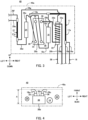
FIG. 1 ,binary refrigeration apparatus 1 includes high-temperatureside refrigeration circuit 10 and low-temperatureside refrigeration circuit 20. - High-temperature
side refrigeration circuit 10 includes high-temperature side compressor 11, high-temperature side condenser 12, high-temperature side dryer 13, high-temperature side decompressor 14, high-temperature side evaporator 15,liquid receiver 16 and high-temperatureside heat exchanger 17. - High-temperature
side heat exchanger 17 is composed of a double tube. The inner tube of high-temperatureside heat exchanger 17 is high-temperature side decompressor 14. In addition, high-temperature side evaporator 15 makes upplate heat exchanger 30 described later.Liquid receiver 16 is formed in a cylindrical shape. - The above-described apparatuses are connected by high-
temperature side pipe 18 so that a high-temperature side refrigerant ejected from high-temperature side compressor 11 returns back to high-temperature side compressor 11. High-temperature side pipe 18 is an example of "pipe". - The high-temperature side refrigerant circulates in the arrow direction illustrated in
FIG. 1 . More specifically, the high-temperature side refrigerant returns to high-temperature side compressor 11 after flowing through high-temperature side compressor 11, high-temperature side condenser 12, high-temperature side dryer 13, high-temperature side decompressor 14, high-temperature side evaporator 15,liquid receiver 16 andouter pipe 17a of high-temperatureside heat exchanger 17, in this order. - Low-temperature
side refrigeration circuit 20 includes low-temperature side compressor 21,spiral heat exchanger 22, low-temperature side condenser 23, low-temperature side dryer 24, low-temperature side decompressor 25, low-temperature side evaporator 26 and low-temperatureside heat exchanger 27. Low-temperature side dryer 24 is an example of "dryer". Low-temperature side dryer 24 is formed in a cylindrical shape.Spiral heat exchanger 22 includesmain tube 22a andspiral tube 22b. -
Main tube 22a is formed in a cylindrical shape through which the low-temperature side refrigerant flows inside.Main tube 22a is disposed such that the axis line direction ofmain tube 22a is set along the up-down direction. -
Spiral tube 22b is wound aroundmain tube 22a in a spiral form such that the low-temperature side refrigerant flows from the upper side toward the lower side ofmain tube 22a.Spiral tube 22b is formed in a rectangular shape in cross section. - Low-temperature
side heat exchanger 27 is composed of a double tube. The inner tube of low-temperatureside heat exchanger 27 is low-temperature side decompressor 25. In addition, low-temperature side condenser 23 makes upplate heat exchanger 30 described later. - The above-described apparatuses are connected by low-
temperature side pipe 28 such that the low-temperature side refrigerant ejected from low-temperature side compressor 21 returns back to low-temperature side compressor 21. Low-temperature side pipe 28 is an example of "pipe". - The low-temperature side refrigerant circulates in the arrow direction illustrated in
FIG. 1 . More specifically, the low-temperature side refrigerant returns to low-temperature side compressor 21 after flowing through low-temperature side compressor 21,spiral tube 22b, low-temperature side condenser 23, low-temperature side dryer 24, low-temperature side decompressor 25, low-temperature side evaporator 26,outer pipe 27a of low-temperatureside heat exchanger 27, andmain tube 22a, in this order. Note that through the refrigeration cycle in low-temperatureside refrigeration circuit 20, an ultra-low temperature of -80°C or below is obtained in low-temperature side evaporator 26. -
Plate heat exchanger 30 exchanges heat between the high-temperature side refrigerant flowing through high-temperature side evaporator 15 and the low-temperature side refrigerant flowing through low-temperature side condenser 23. As illustrated inFIG. 2 ,plate heat exchanger 30 is formed in a cuboid shape. -
Plate heat exchanger 30 includes a plurality ofheat transfer plates 31 andcover plate 32.Heat transfer plate 31 andcover plate 32 are plate members with rectangular shapes in front view.Heat transfer plate 31 is formed in a wave shape in cross section. - The plurality of
heat transfer plates 31 is stacked with a predetermined distance therebetween such that a channel through which one of the high-temperature side refrigerant and the low-temperature side refrigerant flows is formed betweenheat transfer plates 31 adjacent to each other. A high-temperature side channel (not illustrated in the drawing) through which the high-temperature side refrigerant flows and a low-temperature side channel (not illustrated in the drawing) of the low-temperature side refrigerant are formed next to each other with a singleheat transfer plate 31 therebetween. That is, the high-temperature side channel and the low-temperature side channel alternate in the stacking direction of the plurality ofheat transfer plates 31. Further,cover plate 32 is disposed at each of the both ends of the stack of the plurality ofheat transfer plates 31. - High-temperature
side inflow part 33 where the high-temperature side refrigerant enters, high-temperatureside outflow part 34 where the high-temperature side refrigerant flows out, low-temperatureside inflow part 35 where the low-temperature side refrigerant enters and low-temperatureside outflow part 36 are disposed at the plate surface of onecover plate 32. The plate surface ofcover plate 32 where high-temperatureside inflow part 33 and the like are disposed is set asfirst surface 30a ofplate heat exchanger 30. - The high-temperature side refrigerant entered from high-temperature
side inflow part 33 flows through the high-temperature side channel and flows out from high-temperatureside outflow part 34. The low-temperature side refrigerant entered from low-temperatureside inflow part 35 flows through the low-temperature side channel and flows out from low-temperatureside outflow part 36. - The high-temperature side refrigerant and the low-temperature side refrigerant exchange heat through
heat transfer plate 31. In addition, the heat exchange between the high-temperature side refrigerant and the low-temperature side refrigerant is more efficiently performed becauseheat transfer plate 31 is formed in a wave shape in cross section, which generates turbulent flow of the high-temperature side refrigerant and the low-temperature side refrigerant. - In addition, some apparatuses making up
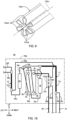
binary refrigeration apparatus 1 make upheat exchanging unit 40 illustrated inFIGS. 3 and 4 . Note that hereafter, for convenience of the following description, the upper and lower sides inFIG. 3 are the upper and lower sides ofheat exchanging unit 40, respectively. Likewise, the left and right sides are the left and right sides ofheat exchanging unit 40, respectively. Likewise, the near and far sides in the drawing are the front and rear sides ofheat exchanging unit 40, respectively. - Heat exchanging
unit 40 includesplate heat exchanger 30, high-temperatureside heat exchanger 17,liquid receiver 16,spiral heat exchanger 22, low-temperature side dryer 24, and low-temperatureside heat exchanger 27. -
Plate heat exchanger 30 is disposed such that the longitudinal direction is set along the up-down direction and thatfirst surface 30a faces the front side. - High-temperature
side heat exchanger 17 is disposed on the right side ofplate heat exchanger 30.Liquid receiver 16 is disposed betweenplate heat exchanger 30 and high-temperatureside heat exchanger 17 such that the longitudinal direction is set along the up-down direction. -
Spiral heat exchanger 22 is disposed betweenliquid receiver 16 and high-temperatureside heat exchanger 17 such that the axis line ofmain tube 22a is set along the up-down direction. Low-temperature side dryer 24 is disposed on the left side ofplate heat exchanger 30 such that the longitudinal direction is set along the up-down direction. Low-temperatureside heat exchanger 27 is disposed on the left side of low-temperature side dryer 24. - In addition,
heat exchanging unit 40 includes a part of high-temperature side pipe 18 and a part of low-temperature side pipe 28 connected to the above-described components. - More specifically, the part of high-
temperature side pipe 18 is first to fifth high-temperature side pipes 18a to 18e. First high-temperature side pipe 18a is a pipe that connects high-temperatureside inflow part 33 ofplate heat exchanger 30 and the inner tube (high-temperature side decompressor 14) of high-temperatureside heat exchanger 17. Second high-temperature side pipe 18b is a portion, on high-temperatureside heat exchanger 17 side, of a pipe that connects the inner tube of high-temperatureside heat exchanger 17 and high-temperature side condenser 12. - Third and fourth high-
temperature side pipes liquid receiver 16. Fifth high-temperature side pipe 18e is a portion, onouter pipe 17a side of high-temperatureside heat exchanger 17, of a pipe that connectsouter pipe 17a of high-temperatureside heat exchanger 17 and high-temperature side compressor 11. - More specifically, the part of low-
temperature side pipe 28 is first to eighth low-temperature side pipes 28a to 28h. First low-temperature side pipe 28a is a pipe that connects low-temperatureside inflow part 35 ofplate heat exchanger 30 andspiral tube 22b. Second low-temperature side pipe 28b is a portion, onspiral tube 22b side, of a pipe that connectsspiral tube 22b and low-temperature side compressor 21. - Third and fourth low-
temperature side pipes temperature side dryer 24. Fifth and sixth low-temperature side pipes side heat exchanger 27 side, of a pipe that connects low-temperatureside heat exchanger 27 and low-temperature side evaporator 26. Seventh low-temperature side pipe 28g is a pipe that connectsouter pipe 27a of low-temperatureside heat exchanger 27 andmain tube 22a. Eighth low-temperature side pipe 28h is a portion, onmain tube 22a side, of a pipe that connectsmain tube 22a and low-temperature side compressor 21. - In addition,
heat exchanging unit 40 is formed such that the length A in a predetermined direction is suppressed. The predetermined direction is a direction perpendicular to the up-down direction. More specifically, the predetermined direction is a direction orthogonal tofirst surface 30a, i.e., the front-rear direction. The length A in the predetermined direction is a length fromsecond surface 30b ofplate heat exchanger 30 opposite tofirst surface 30a to the front end of the pipe connected to high-temperatureside inflow part 33 and the like disposed atfirst surface 30a, for example. - The pipe connected to plate
heat exchanger 30 is bent such that the length A in the predetermined direction is suppressed. Within the range of the length A in the predetermined direction, the above-describedspiral heat exchanger 22 and the like are disposed, and a part of high-temperature side pipe 18 and a part of low-temperature side pipe 28 are laid out. - Heat exchanging
unit 40 further includesheat insulating member 40a that covers each component. Heat insulatingmember 40a is formed of urethane foam, for example. The outer shape of thisheat insulating member 40a is formed in a cuboid shape. A part of high-temperature side pipe 18 and low-temperature side pipe 28 are output from the lower surface and the left surface ofheat insulating member 40a. - Next, the arrangement of
heat exchanging unit 40 infreezer 2 wherebinary refrigeration apparatus 1 is used is described below with reference toFIGS. 5 and 6 . Note that hereafter, for convenience of the following description, the upper and lower sides inFIG. 5 are the upper and lower sides offreezer 2, respectively. Likewise, the left upper side and the lower right side are the front and rear sides offreezer 2, respectively. Likewise, the left lower side and the upper right side are the left and right sides offreezer 2, respectively. -
Freezer 2 includes box 3 with an opening (not illustrated in the drawing) formed on the front side,door 4 that covers the opening of box 3 in an openable and closable manner,lid member 5, andmachine chamber 6. Box 3 includesrear side wall 3a.Rear side wall 3a is an example of "side wall". - Box 3 includes
inner case 3b composed of an iron plate,outer case 3c composed of an iron plate and disposed outsideinner case 3b with a distance therebetween, and heat insulatinglayer 3d formed by foam-filling urethane foam betweeninner case 3b andouter case 3c. Inrear side wall 3a, housing part 3d1 for housingheat exchanging unit 40 is formed. Housing part 3d1 is formed in such a manner thatouter case 3c opens and that heat insulatinglayer 3d is depressed. -
Lid member 5 covers housing part 3d1.Lid member 5 is detachably attached to the back surface of box 3.Lid member 5 includescover panel 5a,first sheet 5b, heat insulatingpanel 5c andsecond sheet 5d. -
Cover panel 5a is composed of an iron plate with a rectangular shape in front view. Incover panel 5a, recess 5a1 depressed from the front side toward the rear side in such a manner thatfirst sheet 5b, heat insulatingpanel 5c andsecond sheet 5d can be installed inside. In addition, at the peripheral portion ofcover panel 5a, flange part 5a2 for attachinglid member 5 torear side wall 3a with a screw is formed, for example. -
First sheet 5b, heat insulatingpanel 5c andsecond sheet 5d are disposed in this order in recess 5a1.First sheet 5b is a flexible sheet formed of polyethylene, and bonded to the bottom surface of recess 5a1, for example. Heat insulatingpanel 5c is a plate-shaped vacuum heat insulation material whose exterior surface is sealed with a resin film, a metal film and/or the like, and is bonded tofirst sheet 5b, for example.Second sheet 5d is a flexible sheet formed of polyethylene, and bonded to heat insulatingpanel 5c, for example. - Heat exchanging
unit 40 is housed in housing part 3d1 such that the up-down direction ofheat exchanging unit 40 is set along the up-down direction offreezer 2, and that the front or rear side ofheat exchanging unit 40 faces the front side offreezer 2. -
Machine chamber 6 is disposed to support box 3. Inmachine chamber 6,compressors condensers side refrigeration circuit 10 and low-temperatureside refrigeration circuit 20 ofbinary refrigeration apparatus 1 are disposed. - Next, a flow of the low-temperature side refrigerant in
spiral tube 22b ofspiral heat exchanger 22 is described. As described above, the low-temperature side refrigerant flown out from low-temperature side compressor 21 entersspiral tube 22b. - As described above,
spiral tube 22b is wound aroundmain tube 22a from the upper side to the lower side (FIG. 3 ). As such, the low-temperature side refrigerant entered intospiral tube 22b flows downward along the up-down direction in a spiral manner. When the low-temperature side refrigerant flows in the above-described manner, turbulent flow of the low-temperature side refrigerant is generated. Further, the length ofspiral tube 22b, the spiral curvature ofspiral tube 22b, and the number of turns ofspiral tube 22b are set to facilitate the generation of turbulent flow. In addition, the cross-sectional shape ofspiral tube 22b is formed in a rectangular shape that facilitates the generation of turbulent flow. The turbulent flow of the low-temperature side refrigerant entersplate heat exchanger 30. - According to the first embodiment,
binary refrigeration apparatus 1 includes low-temperatureside refrigeration circuit 20 includingspiral heat exchanger 22 includingmain tube 22a where the low-temperature side refrigerant that enters low-temperature side compressor 21 enters, andspiral tube 22b wound aroundmain tube 22a in a spiral form where the low-temperature side refrigerant flown out from low-temperature side compressor 21 enters, and high-temperatureside refrigeration circuit 10 where the high-temperature side refrigerant that exchanges heat with the low-temperature side refrigerant throughplate heat exchanger 30 circulates. - In this manner, the low-temperature side refrigerant whose flow is set to turbulent flow by flowing through
spiral tube 22b entersplate heat exchanger 30. In the case where the flow of the fluid is turbulent flow, the heat exchange efficiency is improved in comparison with the case where it is laminar flow. Thus, the heat exchange efficiency inplate heat exchanger 30 is improved. - In addition,
main tube 22a is disposed such that the axis line direction ofmain tube 22a is set along the up-down direction. In addition,spiral tube 22b is wound such that the low-temperature side refrigerant flows from the upper side toward the lower side ofmain tube 22a. - In this manner, the low-temperature side refrigerant flows through
spiral tube 22b downward along the up-down direction, and thus the generation of the turbulent flow of the low-temperature side refrigerant is facilitated. Thus, the heat exchange efficiency inplate heat exchanger 30 is further improved. - In addition, the portion where the low-temperature side refrigerant flows in
spiral tube 22b is formed in a rectangular shape in cross section. - In this manner, the generation of the turbulent flow of the low-temperature side refrigerant is facilitated. Thus, the heat exchange efficiency in
plate heat exchanger 30 is further improved. - In addition,
heat exchanging unit 40 is configured withplate heat exchanger 30,spiral heat exchanger 22, and the part of high-temperature side pipe 18 and the part of low-temperature side pipe 28 disposed at the periphery ofplate heat exchanger 30 andspiral heat exchanger 22. Heat exchangingunit 40 is formed such that the length A in the predetermined direction is suppressed. - In this manner,
plate heat exchanger 30 andspiral heat exchanger 22 can be unitized such that the length A in the predetermined direction is small. Thus, the degree of freedom of the layout ofheat exchanging unit 40 can be improved. - In addition,
plate heat exchanger 30 is formed in a cuboid shape, and high-temperature side pipe 18 and low-temperature side pipe 28 are connected tofirst surface 30a. The predetermined direction is a direction orthogonal tofirst surface 30a. - In this manner, in the direction orthogonal to
first surface 30a, the length ofheat exchanging unit 40 can be suppressed. - In addition,
binary refrigeration apparatus 1 further includesliquid receiver 16 where the high-temperature side refrigerant flown out fromplate heat exchanger 30 enters, and low-temperature side dryer 24 where the low-temperature side refrigerant flown out fromplate heat exchanger 30 enters. Heat exchangingunit 40 further includesliquid receiver 16 and low-temperature side dryer 24. - In this manner,
heat exchanging unit 40 can suppress the length A in the predetermined direction even in the case whereliquid receiver 16 and low-temperature side dryer 24 are provided. - In addition,
heat exchanging unit 40 is covered withheat insulating member 40a and housed inrear side wall 3a of box 3 infreezer 2 wherebinary refrigeration apparatus 1 is used. - In this manner, in comparison with the case where
heat exchanging unit 40 is housed inmachine chamber 6, the thermal influence of the components ofbinary refrigeration apparatus 1 housed inmachine chamber 6 onheat exchanging unit 40 can be suppressed. - Next, a second embodiment of the present disclosure is described mainly about differences from the above-described first embodiment. In this second embodiment, double-
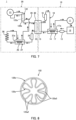
tube heat exchanger 122 illustrated inFIG. 7 is provided instead ofspiral heat exchanger 22 of the first embodiment. Double-tube heat exchanger 122 includesmulti-petal tube 122a andouter tube 122b. -
Multi-petal tube 122a is formed in a tubular shape with a wave shape in the cross section orthogonal to axis line 122a1 (FIGS. 8 and9 ). The side wall ofmulti-petal tube 122a is formed such that a waveform in which peak 122a2 and valley 122a3 alternate in the circumferential direction extends straight along the direction of axis line 122a1 (FIGS. 8 and9 ). - The first end of
multi-petal tube 122a is connected to low-temperature side compressor 21 through second low-temperature side pipe 28b (FIG. 10 ). The second end ofmulti-petal tube 122a is connected to low-temperatureside inflow part 35 ofplate heat exchanger 30 through first low-temperature side pipe 28a. That is, the low-temperature side refrigerant flown out from low-temperature side compressor 21 entersmulti-petal tube 122a. The low-temperature side refrigerant flown out frommulti-petal tube 122a enters low-temperatureside inflow part 35 ofplate heat exchanger 30. -
Outer tube 122b is formed in a tubular shape forhousing multi-petal tube 122a inside (FIG. 8 ). The first end portion ofouter tube 122b is connected toouter pipe 27a of low-temperatureside heat exchanger 27 through seventh low-temperature side pipe 28g (FIG. 10 ). The second end portion ofouter tube 122b is connected to low-temperature side compressor 21 through eighth low-temperature side pipe 28h. - That is, the low-temperature side refrigerant flown out from
outer pipe 27a of low-temperatureside heat exchanger 27 entersouter tube 122b. The low-temperature side refrigerant entered intoouter tube 122b flows between the inner peripheral surface ofouter tube 122b and the outer peripheral surface ofmulti-petal tube 122a. The low-temperature side refrigerant flown out fromouter tube 122b enters low-temperature side compressor 21. - In double-
tube heat exchanger 122, the heat is exchanged between the low-temperature side refrigerant flowing throughmulti-petal tube 122a and the low-temperature side refrigerant flowing throughouter tube 122b.Multi-petal tube 122a, which has a wavy cross-sectional shape as described above, has a larger area of the exterior surface than the case of a circular cross-sectional shape. Thus, the heat exchange in double-tube heat exchanger 122 is more efficiently performed. In addition, double-tube heat exchanger 122 is disposed such that axis line 122a1 ofmulti-petal tube 122a is set along the up-down direction in the heat exchanging unit. - According to the second embodiment,
binary refrigeration apparatus 1 includes low-temperatureside refrigeration circuit 20 including double-tube heat exchanger 122 includingmulti-petal tube 122a formed in a tubular shape with a wave shape in the cross section orthogonal to axis line 122a1 andouter tube 122b formed in a tubular shape forhousing multi-petal tube 122a inside, and high-temperatureside refrigeration circuit 10 where the high-temperature side refrigerant that exchanges heat with the low-temperature side refrigerant throughplate heat exchanger 30 circulates.Multi-petal tube 122a is a tube where the low-temperature side refrigerant flown out from low-temperature side compressor 21 enters. The low-temperature side refrigerant that enters low-temperature side compressor 21 enters between the inner peripheral surface ofouter tube 122b and the outer peripheral surface ofmulti-petal tube 122a. - In this manner, since the inner tube of double-
tube heat exchanger 122 ismulti-petal tube 122a, the generation of the turbulent flow of the low-temperature side refrigerant is more facilitated than the case where the inner tube is a cylinder tube. Thus, the heat exchange efficiency inplate heat exchanger 30 is improved. In addition, since the inner tube of double-tube heat exchanger 122 ismulti-petal tube 122a, the heat exchange can be more efficiently performed. Thus, the length ofmulti-petal tube 122a in the direction along axis line 122a1 can be shortened, and downsizing of double-tube heat exchanger 122 can be achieved. - While
binary refrigeration apparatus 1 according to one or a plurality of aspects are described above based on the embodiments, the present disclosure is not limited to the embodiments. As long as it does not depart from the main purpose of this disclosure, various variations that one skilled in the art can conceive of on the present embodiment, or forms constructed by combining components in different forms, may also be included within the scope of one or more aspects. - While, in the above-described first embodiment,
spiral tube 22b has a rectangular cross-sectional shape, the shape may be a circular shape. - In addition, while, in the above-described first embodiment, the predetermined direction is the direction orthogonal to
first surface 30a, the direction may be the width direction offirst surface 30a. As illustrated inFIG. 11 , the width direction offirst surface 30a is the front-rear direction whenfirst surface 30a ofplate heat exchanger 30 faces the left side. In addition, low-temperature side dryer 24 is disposed on the left side ofplate heat exchanger 30.Spiral heat exchanger 22 andliquid receiver 16 are disposed on the right ofplate heat exchanger 30. In the case where the lengths of low-temperature side dryer 24,spiral heat exchanger 22 andliquid receiver 16 in the front-rear direction, and the layout ofpipes first surface 30a in the width direction, the length A in the predetermined direction corresponds to the length offirst surface 30a in the width direction. Note that also in the second embodiment, the predetermined direction may be the width direction offirst surface 30a instead of the direction orthogonal tofirst surface 30a. - In addition, in the above-described first embodiment,
heat exchanging unit 40 includesplate heat exchanger 30, high-temperatureside heat exchanger 17,liquid receiver 16,spiral heat exchanger 22, low-temperature side dryer 24, and low-temperatureside heat exchanger 27. Alternatively,heat exchanging unit 40 may be configured to include at leastplate heat exchanger 30 andspiral heat exchanger 22. In other words,heat exchanging unit 40 may not include at least one of high-temperatureside heat exchanger 17,liquid receiver 16, low-temperature side dryer 24, and low-temperatureside heat exchanger 27. Note thatheat exchanging unit 40 of the second embodiment may also be configured to include at leastplate heat exchanger 30 and double-tube heat exchanger 122. - In addition, while, in the above-described first embodiment,
heat insulating member 40a ofheat exchanging unit 40 is formed to coverplate heat exchanger 30, high-temperatureside heat exchanger 17,liquid receiver 16,spiral heat exchanger 22, low-temperature side dryer 24, and low-temperatureside heat exchanger 27. Alternatively, heat insulatingmember 40a may be configured to not cover at least one of high-temperatureside heat exchanger 17,liquid receiver 16, low-temperature side dryer 24, and low-temperatureside heat exchanger 27. Note thatheat insulating member 40a ofheat exchanging unit 40 of the second embodiment may also be configured to not cover at least one of high-temperatureside heat exchanger 17,liquid receiver 16, low-temperature side dryer 24, and low-temperatureside heat exchanger 27. - In addition, while
heat exchanging unit 40 is housed inrear side wall 3a of box 3 in the above-described embodiments,heat exchanging unit 40 may be housed in other side walls of box 3, such as the right side wall and/or left side wall of box 3. In this case,heat exchanging unit 40 is housed in the right side wall and/or left side wall such that the up-down direction ofheat exchanging unit 40 is set along the up-down direction offreezer 2, and that the front side or rear side ofheat exchanging unit 40 faces the right side or left side offreezer 2. - In addition, while low-temperature
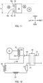
side refrigeration circuit 20 includes low-temperatureside heat exchanger 27 in the above-described embodiments, low-temperatureside heat exchanger 27 may not be provided. In this case, in low-temperatureside refrigeration circuit 20 of the first embodiment, the low-temperature side refrigerant flows through low-temperature side compressor 21,spiral tube 22b, low-temperature side condenser 23, low-temperature side dryer 24, low-temperature side decompressor 25, low-temperature side evaporator 26, andmain tube 22a in this order and returns back to low-temperature side compressor 21 as illustrated inFIG. 12 . In this case, low-temperature side evaporator 26 andmain tube 22a are connected at ninth low-temperature side pipe 128i. In addition, in this case, inheat exchanging unit 40, low-temperature side decompressor 25 may be disposed on the left side ofplate heat exchanger 30 and low-temperature side dryer 24 without being covered byheat insulating member 40a as illustrated inFIG. 13 . Note that inheat exchanging unit 40 of the second embodiment, ninth low-temperature side pipe 128i connects low-temperature side evaporator 26 andouter tube 122b. - In addition, while high-temperature
side refrigeration circuit 10 includes high-temperatureside heat exchanger 17 in the above-described embodiments (FIG. 1 ), high-temperatureside heat exchanger 17 may not be provided. In this case, in high-temperatureside refrigeration circuit 10 of each embodiment, the high-temperature side refrigerant flows through high-temperature side compressor 11, high-temperature side condenser 12, high-temperature side dryer 13, high-temperature side decompressor 14, high-temperature side evaporator 15 andliquid receiver 16 in this order and returns to high-temperature side compressor 11. - In addition, in the above-described second embodiment, the side wall of
multi-petal tube 122a is formed such that the waveform in which peak 122a2 and valley 122a3 alternate in the circumferential direction extends straight along the direction of axis line 122a1. Alternatively, as illustrated inFIG. 14 , the side wall ofmulti-petal tube 222a may be formed such that the waveform spirals around axis line 222a1. In this manner, the generation of the turbulent flow of the low-temperature side refrigerant atmulti-petal tube 222a is further facilitated. - This application is entitled to and claims the benefit of
Japanese Patent Application No. 2020-097933 filed on June 4, 2020 - The binary refrigeration apparatus of the present disclosure is widely applicable to ultra-low-temperature freezers and refrigerators.
-
- 1 Binary refrigeration apparatus
- 2 Freezer
- 3 Box
- 3a Rear side wall (Side wall)
- 3d1 Housing part
- 5 Lid member
- 5 a Cover panel
- 5b First sheet
- 5c Heat insulating panel
- 5d Second sheet
- 10 High-temperature side refrigeration circuit
- 16 Liquid receiver
- 18 High-temperature side pipe (Pipe)
- 20 Low-temperature side refrigeration circuit
- 21 Low-temperature side compressor
- 22 Spiral heat exchanger
- 22a Main tube
- 22b Spiral tube
- 24 Low-temperature side dryer (Dryer)
- 28 Low-temperature side pipe (Pipe)
- 30 Plate heat exchanger
- 30a First surface
- 40 Heat exchanging unit
- 40a Heat insulating member
- 122 Double-tube heat exchanger
- 122a, 222a Multi-petal tube
- 122a1, 222a1 Axis line
- 122b Outer tube
Claims (9)
- A binary refrigeration apparatus comprising:a low-temperature side refrigeration circuit including a spiral heat exchanger including a main tube and a spiral tube wound around the main tube in a spiral form, the main tube being a tube where a low-temperature side refrigerant that flows into a low-temperature side compressor enters, the spiral tube being a tube where the low-temperature side refrigerant flown out from the low-temperature side compressor enters; anda high-temperature side refrigeration circuit where a high-temperature side refrigerant that exchanges heat with the low-temperature side refrigerant through a plate heat exchanger circulates.
- The binary refrigeration apparatus according to claim 1,wherein the main tube is disposed such that a direction of an axis line of the main tube is set along an up-down direction; andwherein the spiral tube is wound such that the low-temperature side refrigerant flows from an upper side to a lower side of the main tube.
- The binary refrigeration apparatus according to claim 1 or 2, wherein a portion where the low-temperature side refrigerant flows in the spiral tube is formed in a rectangular shape in cross section.
- The binary refrigeration apparatus according to any one of claims 1 to 3,wherein the plate heat exchanger, the spiral heat exchanger, and a pipe disposed at a periphery of the plate heat exchanger and the spiral heat exchanger make up a heat exchanging unit, andwherein the heat exchanging unit is formed such that a length in a predetermined direction is suppressed.
- The binary refrigeration apparatus according to claim 4,wherein the plate heat exchanger is formed in a cuboid shape;wherein the pipe is connected to a first surface of the plate heat exchanger; andwherein the predetermined direction is a direction orthogonal to the first surface.
- The binary refrigeration apparatus according to claim 4,wherein the plate heat exchanger is formed in a cuboid shape;wherein the pipe is connected to a first surface of the plate heat exchanger; andwherein the predetermined direction is a width direction of the first surface.
- The binary refrigeration apparatus according to any one of claims 4 to 6, further comprising:a liquid receiver where the high-temperature side refrigerant flown out from the plate heat exchanger enters; anda dryer where the low-temperature side refrigerant flown out from the plate heat exchanger enters,wherein the heat exchanging unit further includes the liquid receiver and the dryer.
- The binary refrigeration apparatus according to any one of claims 4 to 7, wherein the heat exchanging unit is covered with a heat insulating member, and housed in a side wall of a box where the binary refrigeration apparatus is used.
- A binary refrigeration apparatus comprising:a low-temperature side refrigeration circuit including a double-tube heat exchanger including a multi-petal tube formed in a tubular shape with a wave shape in a cross section orthogonal to an axis line and an outer tube formed in a tubular shape for housing the multi-petal tube inside, the multi-petal tube being a tube where a low-temperature side refrigerant flown out from a low-temperature side compressor enters, the outer tube being a tube where the low-temperature side refrigerant that flows into the low-temperature side compressor enters between an inner peripheral surface of the outer tube and an outer peripheral surface of the multi-petal tube; anda high-temperature side refrigeration circuit where a high-temperature side refrigerant that exchanges heat with the low-temperature side refrigerant through a plate heat exchanger circulates.
Applications Claiming Priority (2)
| Application Number | Priority Date | Filing Date | Title |
|---|---|---|---|
| JP2020097933 | 2020-06-04 | ||
| PCT/JP2021/018389 WO2021246137A1 (en) | 2020-06-04 | 2021-05-14 | Binary refrigeration device |
Publications (3)
| Publication Number | Publication Date |
|---|---|
| EP4137754A1 true EP4137754A1 (en) | 2023-02-22 |
| EP4137754A4 EP4137754A4 (en) | 2023-10-11 |
| EP4137754B1 EP4137754B1 (en) | 2025-09-10 |
Family
ID=78830837
Family Applications (1)
| Application Number | Title | Priority Date | Filing Date |
|---|---|---|---|
| EP21816648.6A Active EP4137754B1 (en) | 2020-06-04 | 2021-05-14 | Binary refrigeration device |
Country Status (5)
| Country | Link |
|---|---|
| US (1) | US12326285B2 (en) |
| EP (1) | EP4137754B1 (en) |
| JP (1) | JP7393543B2 (en) |
| CN (1) | CN115667816A (en) |
| WO (1) | WO2021246137A1 (en) |
Families Citing this family (3)
| Publication number | Priority date | Publication date | Assignee | Title |
|---|---|---|---|---|
| IT201700085669A1 (en) * | 2017-07-27 | 2017-10-27 | Sandenvendo Europe S P A | Refrigerating unit of a refrigerated product distributor |
| CN117366896A (en) * | 2022-06-30 | 2024-01-09 | 青岛海尔特种电冰柜有限公司 | Refrigeration system, refrigeration device and control method thereof |
| CN117366894A (en) * | 2022-06-30 | 2024-01-09 | 青岛海尔特种电冰柜有限公司 | Cascade compression refrigeration system, refrigeration device and control method thereof |
Family Cites Families (16)
| Publication number | Priority date | Publication date | Assignee | Title |
|---|---|---|---|---|
| JPS57199767U (en) * | 1981-06-16 | 1982-12-18 | ||
| GB2180921B (en) | 1985-09-25 | 1990-01-24 | Sanyo Electric Co | Refrigeration system |
| JPS6273046A (en) * | 1985-09-25 | 1987-04-03 | 三洋電機株式会社 | Refrigerator |
| JP2002013882A (en) * | 2000-06-30 | 2002-01-18 | Matsushita Refrig Co Ltd | Double pipe heat exchanger and refrigerating cycle device using it |
| JP4684070B2 (en) * | 2005-09-30 | 2011-05-18 | 松本重工業株式会社 | Heat exchanger |
| JP2007303792A (en) * | 2006-05-15 | 2007-11-22 | Sanyo Electric Co Ltd | Refrigeration equipment |
| JP2008232449A (en) * | 2007-03-16 | 2008-10-02 | Sumitomo Light Metal Ind Ltd | Double tube heat exchanger and method for manufacturing the same |
| US8011201B2 (en) | 2009-09-30 | 2011-09-06 | Thermo Fisher Scientific (Asheville) Llc | Refrigeration system mounted within a deck |
| JP2011112351A (en) * | 2009-11-30 | 2011-06-09 | Sanyo Electric Co Ltd | Refrigerating device |
| JP5627416B2 (en) * | 2010-11-26 | 2014-11-19 | 三菱電機株式会社 | Dual refrigeration equipment |
| JP5806993B2 (en) * | 2012-09-19 | 2015-11-10 | パナソニックヘルスケアホールディングス株式会社 | Refrigeration equipment |
| JP6181401B2 (en) * | 2013-03-29 | 2017-08-16 | パナソニックヘルスケアホールディングス株式会社 | Dual refrigeration equipment |
| EP3070417A4 (en) * | 2013-11-12 | 2017-09-27 | Mitsubishi Electric Corporation | Refrigeration system |
| CN106123013A (en) * | 2016-06-30 | 2016-11-16 | 刘启端 | Modularity corrugated plate-type heat exchangers |
| DE102018221086A1 (en) | 2018-12-06 | 2020-06-10 | Robert Bosch Gmbh | Valve for metering a fluid, in particular fuel injection valve |
| JP7668924B1 (en) | 2023-10-25 | 2025-04-25 | 多摩化学工業株式会社 | Colloidal silica and method for producing colloidal silica |
-
2021
- 2021-05-14 EP EP21816648.6A patent/EP4137754B1/en active Active
- 2021-05-14 CN CN202180038693.1A patent/CN115667816A/en active Pending
- 2021-05-14 JP JP2022528511A patent/JP7393543B2/en active Active
- 2021-05-14 WO PCT/JP2021/018389 patent/WO2021246137A1/en not_active Ceased
-
2022
- 2022-11-30 US US18/072,247 patent/US12326285B2/en active Active
Also Published As
| Publication number | Publication date |
|---|---|
| CN115667816A (en) | 2023-01-31 |
| EP4137754B1 (en) | 2025-09-10 |
| EP4137754A4 (en) | 2023-10-11 |
| US20230093643A1 (en) | 2023-03-23 |
| WO2021246137A1 (en) | 2021-12-09 |
| US12326285B2 (en) | 2025-06-10 |
| JP7393543B2 (en) | 2023-12-06 |
| JPWO2021246137A1 (en) | 2021-12-09 |
Similar Documents
| Publication | Publication Date | Title |
|---|---|---|
| US12326285B2 (en) | Binary refrigeration apparatus | |
| US6845631B1 (en) | Absorption refrigerator | |
| KR930001635B1 (en) | Heat exchanger | |
| TW201738518A (en) | Refrigerator | |
| JP7117093B2 (en) | refrigerator | |
| EP3156744B1 (en) | Condenser and refrigerator having same | |
| CN109642778B (en) | air conditioning unit | |
| JP2014020758A (en) | Cold storage heat exchanger | |
| CN111609622B (en) | Refrigerator for preventing air duct of freezer compartment from moving downward | |
| JP2017219212A (en) | Internal heat exchanger integral type accumulator and freezing cycle using the accumulator | |
| JP2024045455A (en) | Heat exchanger and refrigeration cycle device | |
| US20050011222A1 (en) | Absorption refrigerator with ice-maker | |
| JP5329127B2 (en) | Cooling system | |
| JP3326326B2 (en) | Heat exchanger | |
| US11148503B2 (en) | Evaporator with cool storage function | |
| CN221526965U (en) | refrigerator | |
| CN220828910U (en) | Window type air conditioner | |
| CN115135939B (en) | Transport refrigeration unit and transport container | |
| JP3326328B2 (en) | Heat exchanger | |
| KR102693083B1 (en) | Refrigerator | |
| WO2005003656A1 (en) | Absorption refrigerator | |
| US7730742B2 (en) | Accelerated heat exchanger | |
| JP2024064113A (en) | refrigerator | |
| CN117628810A (en) | Refrigerator with a refrigerator body | |
| KR20150056318A (en) | Heat exchanger and refrigerator having the same |
Legal Events
| Date | Code | Title | Description |
|---|---|---|---|
| STAA | Information on the status of an ep patent application or granted ep patent |
Free format text: STATUS: THE INTERNATIONAL PUBLICATION HAS BEEN MADE |
|
| PUAI | Public reference made under article 153(3) epc to a published international application that has entered the european phase |
Free format text: ORIGINAL CODE: 0009012 |
|
| STAA | Information on the status of an ep patent application or granted ep patent |
Free format text: STATUS: REQUEST FOR EXAMINATION WAS MADE |
|
| 17P | Request for examination filed |
Effective date: 20221115 |
|
| AK | Designated contracting states |
Kind code of ref document: A1 Designated state(s): AL AT BE BG CH CY CZ DE DK EE ES FI FR GB GR HR HU IE IS IT LI LT LU LV MC MK MT NL NO PL PT RO RS SE SI SK SM TR |
|
| DAV | Request for validation of the european patent (deleted) | ||
| DAX | Request for extension of the european patent (deleted) | ||
| A4 | Supplementary search report drawn up and despatched |
Effective date: 20230911 |
|
| RIC1 | Information provided on ipc code assigned before grant |
Ipc: F25B 40/00 20060101ALN20230905BHEP Ipc: F25B 39/00 20060101ALI20230905BHEP Ipc: F28D 7/10 20060101ALI20230905BHEP Ipc: F25B 1/00 20060101ALI20230905BHEP Ipc: F25B 7/00 20060101AFI20230905BHEP |
|
| STAA | Information on the status of an ep patent application or granted ep patent |
Free format text: STATUS: EXAMINATION IS IN PROGRESS |
|
| 17Q | First examination report despatched |
Effective date: 20240311 |
|
| RAP3 | Party data changed (applicant data changed or rights of an application transferred) |
Owner name: PHC HOLDINGS CORPORATION |
|
| GRAP | Despatch of communication of intention to grant a patent |
Free format text: ORIGINAL CODE: EPIDOSNIGR1 |
|
| STAA | Information on the status of an ep patent application or granted ep patent |
Free format text: STATUS: GRANT OF PATENT IS INTENDED |
|
| RIC1 | Information provided on ipc code assigned before grant |
Ipc: F25B 40/00 20060101ALN20250408BHEP Ipc: F25B 39/00 20060101ALI20250408BHEP Ipc: F28D 7/10 20060101ALI20250408BHEP Ipc: F25B 1/00 20060101ALI20250408BHEP Ipc: F25B 7/00 20060101AFI20250408BHEP |
|
| INTG | Intention to grant announced |
Effective date: 20250422 |
|
| GRAS | Grant fee paid |
Free format text: ORIGINAL CODE: EPIDOSNIGR3 |
|
| GRAA | (expected) grant |
Free format text: ORIGINAL CODE: 0009210 |
|
| STAA | Information on the status of an ep patent application or granted ep patent |
Free format text: STATUS: THE PATENT HAS BEEN GRANTED |
|
| AK | Designated contracting states |
Kind code of ref document: B1 Designated state(s): AL AT BE BG CH CY CZ DE DK EE ES FI FR GB GR HR HU IE IS IT LI LT LU LV MC MK MT NL NO PL PT RO RS SE SI SK SM TR |
|
| REG | Reference to a national code |
Ref country code: GB Ref legal event code: FG4D |
|
| REG | Reference to a national code |
Ref country code: CH Ref legal event code: EP |
|
| REG | Reference to a national code |
Ref country code: DE Ref legal event code: R096 Ref document number: 602021038440 Country of ref document: DE |
|
| REG | Reference to a national code |
Ref country code: IE Ref legal event code: FG4D Ref country code: NL Ref legal event code: FP |
|
| PG25 | Lapsed in a contracting state [announced via postgrant information from national office to epo] |
Ref country code: NO Free format text: LAPSE BECAUSE OF FAILURE TO SUBMIT A TRANSLATION OF THE DESCRIPTION OR TO PAY THE FEE WITHIN THE PRESCRIBED TIME-LIMIT Effective date: 20251210 |
|
| REG | Reference to a national code |
Ref country code: LT Ref legal event code: MG9D |
|
| PG25 | Lapsed in a contracting state [announced via postgrant information from national office to epo] |
Ref country code: FI Free format text: LAPSE BECAUSE OF FAILURE TO SUBMIT A TRANSLATION OF THE DESCRIPTION OR TO PAY THE FEE WITHIN THE PRESCRIBED TIME-LIMIT Effective date: 20250910 |
|
| PG25 | Lapsed in a contracting state [announced via postgrant information from national office to epo] |
Ref country code: HR Free format text: LAPSE BECAUSE OF FAILURE TO SUBMIT A TRANSLATION OF THE DESCRIPTION OR TO PAY THE FEE WITHIN THE PRESCRIBED TIME-LIMIT Effective date: 20250910 |
|
| PG25 | Lapsed in a contracting state [announced via postgrant information from national office to epo] |
Ref country code: GR Free format text: LAPSE BECAUSE OF FAILURE TO SUBMIT A TRANSLATION OF THE DESCRIPTION OR TO PAY THE FEE WITHIN THE PRESCRIBED TIME-LIMIT Effective date: 20251211 |
|
| PG25 | Lapsed in a contracting state [announced via postgrant information from national office to epo] |
Ref country code: SE Free format text: LAPSE BECAUSE OF FAILURE TO SUBMIT A TRANSLATION OF THE DESCRIPTION OR TO PAY THE FEE WITHIN THE PRESCRIBED TIME-LIMIT Effective date: 20250910 |
|
| PG25 | Lapsed in a contracting state [announced via postgrant information from national office to epo] |
Ref country code: LV Free format text: LAPSE BECAUSE OF FAILURE TO SUBMIT A TRANSLATION OF THE DESCRIPTION OR TO PAY THE FEE WITHIN THE PRESCRIBED TIME-LIMIT Effective date: 20250910 |
|
| PG25 | Lapsed in a contracting state [announced via postgrant information from national office to epo] |
Ref country code: PL Free format text: LAPSE BECAUSE OF FAILURE TO SUBMIT A TRANSLATION OF THE DESCRIPTION OR TO PAY THE FEE WITHIN THE PRESCRIBED TIME-LIMIT Effective date: 20250910 Ref country code: BG Free format text: LAPSE BECAUSE OF FAILURE TO SUBMIT A TRANSLATION OF THE DESCRIPTION OR TO PAY THE FEE WITHIN THE PRESCRIBED TIME-LIMIT Effective date: 20250910 |
|
| PG25 | Lapsed in a contracting state [announced via postgrant information from national office to epo] |
Ref country code: RS Free format text: LAPSE BECAUSE OF FAILURE TO SUBMIT A TRANSLATION OF THE DESCRIPTION OR TO PAY THE FEE WITHIN THE PRESCRIBED TIME-LIMIT Effective date: 20251210 |
|
| PG25 | Lapsed in a contracting state [announced via postgrant information from national office to epo] |
Ref country code: ES Free format text: LAPSE BECAUSE OF FAILURE TO SUBMIT A TRANSLATION OF THE DESCRIPTION OR TO PAY THE FEE WITHIN THE PRESCRIBED TIME-LIMIT Effective date: 20250910 |