EP4137732B1 - Quick connector with verifier - Google Patents
Quick connector with verifier Download PDFInfo
- Publication number
- EP4137732B1 EP4137732B1 EP22190762.9A EP22190762A EP4137732B1 EP 4137732 B1 EP4137732 B1 EP 4137732B1 EP 22190762 A EP22190762 A EP 22190762A EP 4137732 B1 EP4137732 B1 EP 4137732B1
- Authority
- EP
- European Patent Office
- Prior art keywords
- verifier
- socket
- opening
- extending
- fluid tube
- Prior art date
- Legal status (The legal status is an assumption and is not a legal conclusion. Google has not performed a legal analysis and makes no representation as to the accuracy of the status listed.)
- Active
Links
Images






Classifications
-
- F—MECHANICAL ENGINEERING; LIGHTING; HEATING; WEAPONS; BLASTING
- F16—ENGINEERING ELEMENTS AND UNITS; GENERAL MEASURES FOR PRODUCING AND MAINTAINING EFFECTIVE FUNCTIONING OF MACHINES OR INSTALLATIONS; THERMAL INSULATION IN GENERAL
- F16L—PIPES; JOINTS OR FITTINGS FOR PIPES; SUPPORTS FOR PIPES, CABLES OR PROTECTIVE TUBING; MEANS FOR THERMAL INSULATION IN GENERAL
- F16L37/00—Couplings of the quick-acting type
- F16L37/08—Couplings of the quick-acting type in which the connection between abutting or axially overlapping ends is maintained by locking members
- F16L37/12—Couplings of the quick-acting type in which the connection between abutting or axially overlapping ends is maintained by locking members using hooks, pawls, or other movable or insertable locking members
- F16L37/1225—Couplings of the quick-acting type in which the connection between abutting or axially overlapping ends is maintained by locking members using hooks, pawls, or other movable or insertable locking members using a retaining member the extremities of which, e.g. in the form of a U, engage behind a shoulder of both parts
-
- F—MECHANICAL ENGINEERING; LIGHTING; HEATING; WEAPONS; BLASTING
- F16—ENGINEERING ELEMENTS AND UNITS; GENERAL MEASURES FOR PRODUCING AND MAINTAINING EFFECTIVE FUNCTIONING OF MACHINES OR INSTALLATIONS; THERMAL INSULATION IN GENERAL
- F16L—PIPES; JOINTS OR FITTINGS FOR PIPES; SUPPORTS FOR PIPES, CABLES OR PROTECTIVE TUBING; MEANS FOR THERMAL INSULATION IN GENERAL
- F16L37/00—Couplings of the quick-acting type
- F16L37/08—Couplings of the quick-acting type in which the connection between abutting or axially overlapping ends is maintained by locking members
- F16L37/084—Couplings of the quick-acting type in which the connection between abutting or axially overlapping ends is maintained by locking members combined with automatic locking
- F16L37/088—Couplings of the quick-acting type in which the connection between abutting or axially overlapping ends is maintained by locking members combined with automatic locking by means of a split elastic ring
- F16L37/0885—Couplings of the quick-acting type in which the connection between abutting or axially overlapping ends is maintained by locking members combined with automatic locking by means of a split elastic ring with access to the split elastic ring from a radial or tangential opening in the coupling
-
- F—MECHANICAL ENGINEERING; LIGHTING; HEATING; WEAPONS; BLASTING
- F16—ENGINEERING ELEMENTS AND UNITS; GENERAL MEASURES FOR PRODUCING AND MAINTAINING EFFECTIVE FUNCTIONING OF MACHINES OR INSTALLATIONS; THERMAL INSULATION IN GENERAL
- F16L—PIPES; JOINTS OR FITTINGS FOR PIPES; SUPPORTS FOR PIPES, CABLES OR PROTECTIVE TUBING; MEANS FOR THERMAL INSULATION IN GENERAL
- F16L2201/00—Special arrangements for pipe couplings
- F16L2201/10—Indicators for correct coupling
Definitions
- the field relates to fluid connectors. More particularly, this disclosure relates to a quick connector with a verifier that visually indicates a correct fluid connection.
- Quick connectors find use in the automotive and other industries for coupling fluid piping.
- a tube is joined to another device such as a pump, tank, or another tube.
- the quick connector may have a tubular female receptacle body arranged to sealingly receive a male tube therein.
- the male tube may include an endform adapted to make a snap engagement with the female receptacle body and provide a locking relationship between the endform and the female receptacle body.
- Use of quick connectors is advantageous in that a sealed and secured fluid line may be established with a minimum amount of time and expense.
- US 10 816 121 B2 , US 2016/069496 A1 , EP 3 521 676 A2 and DE 20 2020 103903 U1 each disclose examples of such quick connectors.
- a first embodiment of this disclosure provides a quick connector assembly that couples a fluid line between a first and a second fluid tube.
- the quick connector assembly comprises a receptacle body having a cavity extending through the receptacle body to a stem portion connected to the second fluid tube.
- a sealing section is located within the cavity and a socket portion extends from the sealing section.
- the socket portion includes a wall bordering a socket opening in alignment with the cavity.
- a pair of latch openings extend through a portion of the wall into the socket opening.
- a sealing member having a receiver opening is installed in the sealing section with the receiver opening in alignment with the socket opening and the stem portion.
- a bracket is installed on the wall and includes a pair of spring latches with each spring latch extending through a respective one of the pair of the latch openings into the socket opening.
- a first fluid tube having an insertion portion and a raised upset has the insertion portion placed through the socket opening into the receiver opening making a fluid connection to the second fluid tube and causing the upset to be captured by each spring latch retaining the first fluid tube to the receptacle body.
- a process for forming a coupling in a fluid line between a first and second fluid tube comprises, coupling the second fluid tube to a stem of a receptacle body that has a cavity extending through the receptacle body.
- a sealing member having a receiver opening in alignment with the socket opening and the stem portion is installed in a sealing section formed within the cavity.
- a socket portion extends from the sealing section that includes a wall bordering a socket opening in alignment with the receiver opening.
- a pair of latch openings extend through a portion of the wall into the socket opening and a bracket is installed on the wall that includes a pair of spring latches with each spring latch extending through a respective one of the pair of the latch openings into the socket opening.
- the process further includes forming an endform on the first fluid tube including an insertion portion and a raised upset and inserting the insertion portion through the socket opening into the receiver opening wherein the first fluid tube makes a fluid coupling to the second fluid tube and causing the upset to be captured by each spring latch and retaining the first fluid tube to the receptacle body.
- a verifier is used in both the first and second embodiments to verify the coupling of the first fluid tube to the receptacle body.
- the verifier includes fixing fingers and a pair of arms. Each arm extends from either side of a push surface.
- the verifier arms and fixing fingers are installed through respective recesses in the wall into the socket opening.
- a force applied to the verifier push surface causes each verifier arm to travel along the sides of the first fluid tube upset to rest below a respective spring latch and the fixing fingers to capture the first fluid tube upset.
- Verifier symbols located on a surface on each verifier arm are visible through the latch openings verifying the coupling of the first fluid tube to the receptacle body.
- each verifier arm further includes a billboard member having verifier symbols located on a billboard surface, wherein each billboard surface is visible through a respective latch opening when each verifier arm extends fully into the socket cavity, verifying the coupling of the first fluid tube to the receptacle body.
- the verifier is placed in an installed condition by applying a force to the verifier push surface.
- FIG. 1 An exploded view of an example quick connector assembly 10 for coupling a fluid line to another fluid line, is illustrated in FIG. 1 .
- the quick connector assembly 10 is used to form a fluid connection in a fluid line between a first fluid tube 12 and a second fluid tube (not shown) installed on a stem 25 of a receptacle body 20.
- the first fluid tube 12 may be a pipe, a hose, or any other fluid conveying component.
- the first fluid tube 12 includes an endform 14 of a tubular configuration arranged to be accepted within a complementary female socket portion 27 of the receptacle body 20 and along generally a longitudinal axis A about which the quick connector 10 is arranged.
- the endform 14 includes a cylindrical insertion portion 15 and a raised upset 18.
- the raised upset 18 extending circumferentially about the exterior of endform 14.
- the upset 18 may be formed integrally from the material of the endform 14 during its manufacture or may be a separate component bonded to the exterior of endform 14.
- the quick connector assembly 10 of the present disclosure further includes a sealing member 30, a bracket 50, and a verifier 80.
- the receptacle body 20 is a tubular member defining a male end that forms the stem 25.
- Stem 25 extends axially from a female end or socket portion 27.
- the stem 25 generally includes various ribs, ridges, and grooves 90 for coupling to the interior cavity of the second fluid tube.
- the various ribs, ridges, and grooves 90 of stem 25 may take several configurations depending on the structure of the second fluid tube attached over stem 25.
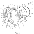
- the socket portion 27 is structured for accepting therein a sealing member 30 through an internal cavity 29, shown on FIG. 2 .
- the cavity 29 extends from the socket portion 27 through stem 25 and forms a portion of the fluid line.
- the quick connector 10 further includes a sealing member 30, a bracket 50, and a verifier 80.
- FIGS. 1-3 illustrate an example of a sealing member 30 of the present disclosure and its installation into receptacle body 20.
- the sealing member 30 has a cylindrical outer diameter that is complementary to a cylindrical inner diameter of cavity 29 at a sealing section 28 of the socket portion 27.
- the socket portion 27 is generally D-shaped in configuration and has a socket opening 74 leading into the internal cavity 29.
- the entrance to the sealing section 28 extends from the annular abutment surface 21 to an annular end stop surface 23 having a cylindrical internal wall 22 therebetween.
- the sealing member 30 is comprised of a cylindrical body 31 having a receiver opening 39 extending through the sealing member 30.
- the receiver opening 39 has an inner cylindrical diameter that matches the outer cylindrical diameter of the insertion portion 15 of endform 14.
- the body 31 has an outer cylindrical diameter that allows the outer surface 32 of body 31 to be housed internally within the sealing section 28.
- the sealing member 30 further includes an annular flange 37 on a first end 38 of the body 31.
- the flange 37 extends outward from the body 31 and includes a front planar face 33 and an annular shoulder 36.
- a second end 40 of the sealing member 30 includes a pair of channels 41 extending about the body 31 separated by a spacer ring 42.
- the spacer ring 42 has outer diameter that is substantially similar to the diameter of body 31. Inner portions of each channel 41 opens into receiver opening 39. A pair of elastomeric seals, such as for example, O-rings 43 are arranged to be installed in each channel 41. Portions of each O-ring 43 extend through the opening in each channel 41 and into receiver opening 39.
- the body 31 further includes a pair of windows 45 located in opposition to each other extending through the body 31 to receiver opening 39.
- An L-shaped sealing member latch 46 extends from each window 45.
- the sealing member latches 46 include a first leg 47 extending from the body member surface 32 from each window 45 and a second leg 48 extending perpendicularly from the first leg 47, the second leg 48 extending outward from each window 45.
- the sealing member 30 is installed into socket portion 27 and press-fit into the sealing section 28 by aligning sealing member latches 46 with sealing section openings 24 extending through the sealing section 28 and pushing the sealing member axially into cavity 29 until shoulder 36 rests on abutment surface 21 and the second end 40 contacts stop surface 23.
- each second leg 48 of each latch 46 is deflected and urged inward by the abutment surface 21. As can be best seen in FIG.
- the second leg of latches 46 travel across surface 22 of the sealing section until they reach a respective sealing section opening 24, wherein each second leg 48 is allowed to return to its normal shape and spring outward of opening 24 locking the sealing member 30 in position in the sealing section 28.
- Each O-ring is elastically deformed between their individual groove 41 and the cavity 29 wall 22 forming a fluid tight seal between the sealing member 30 and the sealing section 28.
- the sealing member 30 and its elements, except for the O-rings are formed of a rigid material, such as for example, a thermoplastic.
- the sealing member 30 can be removed from the sealing section 28 by pushing-in sealing member latches 46 away from opening24 and extracting the sealing member 30 through cavity 29. This can be easily done in the field, allowing for a technician to install other specific sealing members 30 sized to be used with other types and diameters of tube endforms.
- FIGS. 1 and 4 illustrate an example bracket 50 of the present disclosure.
- the bracket 50 is arranged to capture endform 14 when the endform 14 is installed in the socket portion 27 of the receptacle body 20.
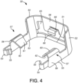
- the bracket 50 is comprised of a rear bulkhead 58 extending into a pair of curved walls 52. Each wall 52 is located on an opposite side of the bulkhead 58.
- a pair of legs 53 project outward from a portion of each curved wall 52.
- the pair of legs 53 includes one leg 53 projecting from a portion of a first curved wall 52 and another leg 53 projecting from a second curved wall 52 on an opposite end of bulkhead 58 such that the pair of legs 53 are laterally spaced apart.
- Each leg 53 terminates at a hook-shaped finger 54.
- Each finger 54 includes an inwardly facing flange member 55.
- Each leg 53 further includes a spring latch 57 extending from each leg.
- Each spring latch 57 has a first member 59 extending perpendicularly from a respective leg 53 and second member 60 folded over and oriented at an acute angle from the first member 59.
- the second member 60 of each spring latch 57 is arranged to allow deflection of the second member 60 toward the first member 59 when a force is applied to a top surface 61 and to resist bending of the second member 60 when a force is applied to a bottom surface 62.
- the bracket 50 further includes a lower wall section 51 extending along the back of the bracket 50 in alignment with the bulkhead 58 between the pair of curved walls 52.
- An opening 66 extends into a pair of recesses 65.
- the opening 66 is formed between the bulkhead 58 and the wall section 51.
- Each recess 65 is adapted to receive therethrough a respective arm 82 of the verifier 80 when the verifier ins installed to the bracket 50.
- a clasping hook 68 extends inward from bulkhead 58 and is arranged to engage a locking notch 88 on the verifier 80.
- the bracket 50 is preferably formed as a unitary structure from a metal material, such as for example, a spring steel. However, it could also be formed from other resilient materials, such as for example, molded from a thermoplastic that would allow the proper deflection of the second member 60 of spring latches 57.
- the bracket 50 is arranged to be installed to an upper section 44 of socket portion 27 after installation of sealing member 30 within the sealing section 28.
- the upper section 44 is generally "D" shaped and includes a peripheral wall 70 extending about the socket opening 74.
- Wall 70 includes a pair of curved wall sections 72 extending from a bulkhead wall section 78. Curved wall sections 72 and bulkhead wall section 78 have external faces that conform to the internal faces of curved walls 52 and bulkhead 58 respectively, of the bracket 50.
- Wall 70 includes a pair of wall sections 73 located opposite of the other on either side of the socket opening 74.
- a pair of latch openings 71 are formed through wall 70 adjacent wall sections 73.
- a pair of flange member openings 77 extend through wall 70 each located on an opposite end of the wall 70. Each flange member opening 77 is arranged to accept therein a respective flange member 55 of each leg 53 of bracket 50.
- a pair of verifier recesses 75 extend from each side of a central opening 76 which extend through wall 70 below bulkhead section 58. The pair of verifier recesses 75 and central opening 76 have a general shape and dimension as to conform to recesses 65 and opening 66 respectively of the bracket 50. In combination, recesses 65 and 75 and openings 66 and 76 provide a passthrough to accept the installation of verifier 80 through the bracket 50 and the upper section 44 wall 70 of the socket portion 27.
- FIG. 6 illustrates the bracket 50 installed in the upper section 44 of the socket portion 27 in an endform accepting position.
- a respective second member 60 extends through a respective opening 71 into the socket opening 74.
- the bracket 50 is held in the installation ready condition by the grasping a flange members 55 in flange member openings 77.
- the verifier 80 includes a crossmember 81 having a pair of arms 82 which project from opposite ends of the crossmember 81.
- the pair of arms includes one arm 82 projecting from one end of the crossmember 81 and another arm 82 projecting from the opposite end of the crossmember 81 such that the arms 82 are laterally spaced apart and are identical to the other.
- Each arm 82 includes a stop member 83 extending perpendicularly from a top surface of each arm and a billboard member 84 located adjacent to each stop member 83.
- Each billboard member 84 includes a generally planar surface 85 arranged to have verifying indicia, for example a QR code or other distinguishing marks printed or applied on surface 85 to provide a visual or machine readable verification of the proper installation of the endform 14.
- the verifier 80 crossmember 81 further includes a push surface 86 extending perpendicularly from the crossmember 81 and a set of fixing fingers 87 extending perpendicularly from a top surface of the crossmember 81.
- the fixing fingers 87 extend from crossmember 81 generally parallel to arms 82.
- a locking notch 88 is formed on a center finger of the locking fingers 87 adjacent the push surface 86.
- Each arm 82 includes a chamfered surface 89 formed on the inner face of each arm 82 that slope radially upward from the inner face of each arm 82.
- the inner edges of the arms 82 are spaced apart a distance smaller than the outer diameter of the upset 18 formed about endform 14.
- the outer edges of each arm 82 are generally linear or straight in orientation and arranged to fit within the recesses 65 of the bracket 50 and the recesses 75 of the socket portion 27 upper portion 44.
- the verifier 80 is formed of a resilient material, preferably molded from a thermoplastic, such that each arm 82 may flex and deflect radially outwardly as the verifier 80 is installed. That is, the chamfered surfaces 89 of each arm 82 travel against an installed upset 18 and arranged to urge each arms 82 laterally outward as arms 82 travel across the upset 18 which will be explained in more detail below.
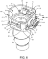
- FIG. 6 illustrates an example embodiment of the present disclosure wherein the quick connector assembly 10 is in an installation ready condition, such as for example, when the quick connector assembly 10 is manufactured and ready to accept within the socket opening 74 an endform 14.
- the sealing member 30 is installed in sealing section 28, and the bracket 50 and the verifier 80 are installed to the socket portion 27.
- the bracket 50 is installed on the wall 70 of socket portion 27 upper section 44 with a respective second member 60 of the spring latches 57 extending through a respective opening 71.
- Each second member 60 of each spring latch 57 extends into the socket cavity 74.
- the bracket 50 is retained in the installation ready condition by the action of a respective flange member 55 grasping a respective flange member opening 77.
- the verifier 80 has each arm 82 inserted into the socket cavity 74 through a respective recess 65 of the bracket 50. Fixing fingers 87 are partially inserted through opening 66. Opening 66 and recesses 65 are located above wall 51 on the bracket 50 and thereby positions the verifier arms 82 and fixing fingers 87 above the surface 33 of the sealing member 30.
- the verifier 80 is prevented from being fully inserted into the socket cavity 74 by a front surface of each stop member 83 engaging an edge of bulkhead 58. Additional movement of the verifier 80 into socket cavity 74 would require the each stop member 83 be disengaged from the edge of bulkhead 58 to allow the stop members 83 to enter the socket cavity 74 through their respective recesses 65. This can only be accomplished when the endform 14 is installed in the socket cavity 74.
- the insertion portion 15 of the endform 14 is aligned with and inserted into receiver opening 39 of the sealing member 30.
- the upset 18 enters the socket cavity 74 and contacts the top surface 61 of each second member 60 of the spring latches 57.
- a continued applied force in axial direction A will cause deflection of each second member 60 inwardly toward the first member 59 by the upset 18 pushing each second member 60 away from the upset 18.
- each of the second members 60 returns to its relaxed position capturing the upset 18 between the sealing member surface 33 and a bottom surface 62 of each spring latch second member 60, as is best seen in FIG. 8 .
- the endform 14 is now in an installed condition and retained within socket portion 27.
- the insertion portion 15 of endform 14 is installed within receiver opening 39 of the sealing member 30 making a fluid tight seal between the endform 14 and the sealing member 30 by elastically deforming the O-rings 43 against the insertion portion 15 that extend into receiver opening 39 from the channel 41 openings.
- each arm 82 aligns with an outer edge of upset 18.
- Applying a force to push surface 86 in direction B will cause each arm of the verifier 80 to travel along the exterior surface of the upset 18.
- Each arm 82 will be deflected outwardly toward the wall 70 as it travels along the upset 18 exterior surface. The outward deflection will disengage each stop member 83 from the edge of the bulkhead 58 allowing each stop member 83 to enter the socket cavity 74 via a respective recess 65 and 75.
- the placement of the fixing fingers 87 over the upset 18 enhances the hold of the upset 18, assuring that the endform 14 is held firmly in the socket portion 27.
- the verifier 80 With the capture of the clasping hook 68 by the notch 88, the verifier 80 now becomes locked to bracket 50. Any subsequent movement of the bracket 50, such as for example, movement of the bracket 50 to unlatch the endform 14 from the receptacle body 20 will now also move the verifier 80.
- each billboard member 84 surface 85 becomes visible through a respective opening 71 of the socket portion 27.
- a QR code applied on each surface 85 becomes visible through a respective opening 71.
- the QR code can be read by a hand held visual scanner allowing for machine scanning and recording of the positive engagement of the endform 14 to the receptacle body 20. It will be appreciated by those skilled in the art that other forms of code or indicia may be printed on surface 85 to provide a visible indication of a positive engagement of the endform 14 to the receptacle body 20.
- the endform 14 can be removed from the receptacle body 20 for servicing or replacement.
- each flange member 55 on each bracket arm 53 is manually removed from a respective flange member opening 77 and the bracket 50 moved backward in direction C as shown in FIG. 11 , thereby placing the quick connector assembly 10 into a serviceable condition.
- the bulkhead 58 and the curved walls 52 of bracket 50 are pulled back from the socket portion 27 curved wall sections 72 until each flange member 55 enters into a respective retainer notch 79 and arresting any further backward movement of the bracket 50.
- each second member 60 of each spring latch 57 is moved to a position where each member 60 is not located over upset 18. Since the verifier 80 now moves along with the bracket 50, the backward movement of the bracket 50 also moves fixing fingers 87 into a position where the fixing fingers 87 are not located over upset 18.
- the endform 14 can now be removed from the receptacle body 20 by pulling the endform 14 from socket portion 27 in direction D.
- the endform 14 can be reinstalled into socket portion 27 and the bracket 50 repositioned to capture the endform 14.
- Reapplying a force to push surface 86 in direction B disengages flange members 55 from retainer notches 79 moving the bracket 50 back into the installed condition and engage flange members 55 to respective flange member openings 77 of the installed condition as shown in FIG. 9 .
- verifier 80 also now moves in concert with the bracket 50 movement of the bracket 80 into the installed condition will also move the verifier 80 into the verification condition as shown in FIG. 10 .
- the quick connector assembly described herein provides the benefits of only requiring access from one side, for example, top, bottom, left or right in order to operate the components of the connector (e.g., retainer and verifier) and to connect the fluid tubes together.
- the quick connector assembly of the present disclosure can be coupled to male and female components in any radial direction, the quick connector assembly can be oriented to provide the most convenient access for an installer or user. In this way, packaging of the quick connector assembly is improved, and routing of fluid lines is made more robust and variable in a variety of different environments.
- the quick connector assembly has numerous applications where a fluid-tight, but serviceable connection is desired. Within the industry a serviceable connection is a connection were the fluid carrying components of a quick connector can be disconnected from each other for the purposes of maintenance or the servicing of components of the quick connector assembly.
Landscapes
- Engineering & Computer Science (AREA)
- General Engineering & Computer Science (AREA)
- Mechanical Engineering (AREA)
- Quick-Acting Or Multi-Walled Pipe Joints (AREA)
Description
- This application claims priority under 35 U.S.C. § 119(e) to
U.S. Provisional Patent Application No. 63/234,243 - The field relates to fluid connectors. More particularly, this disclosure relates to a quick connector with a verifier that visually indicates a correct fluid connection.
- Quick connectors find use in the automotive and other industries for coupling fluid piping. In such couplings, a tube is joined to another device such as a pump, tank, or another tube. The quick connector may have a tubular female receptacle body arranged to sealingly receive a male tube therein. The male tube may include an endform adapted to make a snap engagement with the female receptacle body and provide a locking relationship between the endform and the female receptacle body. Use of quick connectors is advantageous in that a sealed and secured fluid line may be established with a minimum amount of time and expense.
US 10 816 121 B2US 2016/069496 A1 ,EP 3 521 676 A2 andDE 20 2020 103903 U1 - A first embodiment of this disclosure provides a quick connector assembly that couples a fluid line between a first and a second fluid tube. The quick connector assembly comprises a receptacle body having a cavity extending through the receptacle body to a stem portion connected to the second fluid tube. A sealing section is located within the cavity and a socket portion extends from the sealing section. The socket portion includes a wall bordering a socket opening in alignment with the cavity. A pair of latch openings extend through a portion of the wall into the socket opening. A sealing member having a receiver opening is installed in the sealing section with the receiver opening in alignment with the socket opening and the stem portion. A bracket is installed on the wall and includes a pair of spring latches with each spring latch extending through a respective one of the pair of the latch openings into the socket opening. A first fluid tube having an insertion portion and a raised upset has the insertion portion placed through the socket opening into the receiver opening making a fluid connection to the second fluid tube and causing the upset to be captured by each spring latch retaining the first fluid tube to the receptacle body.
- In a second embodiment a process for forming a coupling in a fluid line between a first and second fluid tube is disclosed. The process comprises, coupling the second fluid tube to a stem of a receptacle body that has a cavity extending through the receptacle body. A sealing member having a receiver opening in alignment with the socket opening and the stem portion is installed in a sealing section formed within the cavity. A socket portion extends from the sealing section that includes a wall bordering a socket opening in alignment with the receiver opening. A pair of latch openings extend through a portion of the wall into the socket opening and a bracket is installed on the wall that includes a pair of spring latches with each spring latch extending through a respective one of the pair of the latch openings into the socket opening. The process further includes forming an endform on the first fluid tube including an insertion portion and a raised upset and inserting the insertion portion through the socket opening into the receiver opening wherein the first fluid tube makes a fluid coupling to the second fluid tube and causing the upset to be captured by each spring latch and retaining the first fluid tube to the receptacle body.
- A verifier is used in both the first and second embodiments to verify the coupling of the first fluid tube to the receptacle body. The verifier includes fixing fingers and a pair of arms. Each arm extends from either side of a push surface. The verifier arms and fixing fingers are installed through respective recesses in the wall into the socket opening. Upon capture of the first fluid tube upset by each of the spring latches, a force applied to the verifier push surface causes each verifier arm to travel along the sides of the first fluid tube upset to rest below a respective spring latch and the fixing fingers to capture the first fluid tube upset. Verifier symbols located on a surface on each verifier arm are visible through the latch openings verifying the coupling of the first fluid tube to the receptacle body. The fixing fingers capture the first fluid tube upset when each verifier arm extends fully into the socket cavity on either side of the upset; and each verifier arm further includes a billboard member having verifier symbols located on a billboard surface, wherein each billboard surface is visible through a respective latch opening when each verifier arm extends fully into the socket cavity, verifying the coupling of the first fluid tube to the receptacle body. In the second embodiment, the verifier is placed in an installed condition by applying a force to the verifier push surface.
- For a more complete understanding of this disclosure, reference is now made to the following description, taken in conjunction with the accompanying drawings, in which:
-
FIG. 1 illustrates an example exploded isometric view of an example quick connector in accordance with the present disclosure; -
FIG. 2 illustrates an isometric view of a socket portion of the example quick connector in accordance with the present disclosure; -
FIG. 3 illustrates an isometric view of a sealing member of the example quick connector in accordance with the present disclosure; -
FIG. 4 illustrates an isometric view of a bracket, of the example quick connector in accordance with the present disclosure; -
FIG. 5 illustrates an isometric view of a verifier, of the example quick connector in accordance with the present disclosure; -
FIG. 6 illustrates an isometric view of the example quick connector receptacle body in an installation ready condition in accordance with the present disclosure; -
FIG. 7 illustrates an isometric view of the example quick connector receptacle body in an installed condition in accordance with the present disclosure; -
FIG. 8 illustrates a sectional view ofFIG. 7 of the example quick connector in the installed condition in accordance with the present disclosure; -
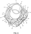
FIG.9 illustrates an isometric view of the example quick connector in the verification condition, in accordance with the present disclosure; -
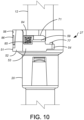
FIG. 10 illustrates a side elevational view of the example quick connector ofFIG. 9 , illustrating a verification feature in accordance with the present disclosure; and -
FIG. 11 illustrates an isometric view of the example quick connector in a serviceable condition in accordance with the present disclosure. - All figures serve illustrative purposes only and are not intended to limit the scope of the present invention. The drawings are generally to scale, but some features may not be true to scale and serve to emphasize certain details of the various aspects of the invention. Common items between different embodiments of the figures have common reference numerals. It should be noted that for purposes of clarity, the quick connector of the present disclosure is shown with its longitudinal extent position in a horizontal plane and the terms "top," "bottom," have been used in describing the connector body. However, in use, the quick connector coupling can reside in any orientation without regard to the horizontal and vertical planes and "top," "bottom," "sides," and "lateral" are thus used in relation to the figures and illustrations herein.
- An exploded view of an example
quick connector assembly 10 for coupling a fluid line to another fluid line, is illustrated inFIG. 1 . As is shown inFIG. 1 , thequick connector assembly 10 is used to form a fluid connection in a fluid line between afirst fluid tube 12 and a second fluid tube (not shown) installed on astem 25 of areceptacle body 20. Thefirst fluid tube 12 may be a pipe, a hose, or any other fluid conveying component. Thefirst fluid tube 12 includes anendform 14 of a tubular configuration arranged to be accepted within a complementaryfemale socket portion 27 of thereceptacle body 20 and along generally a longitudinal axis A about which thequick connector 10 is arranged. Theendform 14 includes acylindrical insertion portion 15 and a raisedupset 18. The raisedupset 18 extending circumferentially about the exterior ofendform 14. Theupset 18 may be formed integrally from the material of theendform 14 during its manufacture or may be a separate component bonded to the exterior ofendform 14. Thequick connector assembly 10 of the present disclosure further includes asealing member 30, abracket 50, and averifier 80. - The
receptacle body 20 is a tubular member defining a male end that forms thestem 25.Stem 25 extends axially from a female end orsocket portion 27. Thestem 25 generally includes various ribs, ridges, andgrooves 90 for coupling to the interior cavity of the second fluid tube. The various ribs, ridges, andgrooves 90 ofstem 25 may take several configurations depending on the structure of the second fluid tube attached overstem 25. Thesocket portion 27 is structured for accepting therein a sealingmember 30 through aninternal cavity 29, shown onFIG. 2 . Thecavity 29 extends from thesocket portion 27 throughstem 25 and forms a portion of the fluid line. Thequick connector 10 further includes a sealingmember 30, abracket 50, and averifier 80. -
FIGS. 1-3 illustrate an example of a sealingmember 30 of the present disclosure and its installation intoreceptacle body 20. The sealingmember 30 has a cylindrical outer diameter that is complementary to a cylindrical inner diameter ofcavity 29 at asealing section 28 of thesocket portion 27. As can be seen inFIG. 2 , thesocket portion 27 is generally D-shaped in configuration and has asocket opening 74 leading into theinternal cavity 29. The entrance to thesealing section 28 extends from theannular abutment surface 21 to an annularend stop surface 23 having a cylindricalinternal wall 22 therebetween. - As is illustrated in
FIG. 3 , the sealingmember 30 is comprised of acylindrical body 31 having areceiver opening 39 extending through the sealingmember 30. Thereceiver opening 39 has an inner cylindrical diameter that matches the outer cylindrical diameter of theinsertion portion 15 ofendform 14. Thebody 31 has an outer cylindrical diameter that allows the outer surface 32 ofbody 31 to be housed internally within the sealingsection 28. The sealingmember 30 further includes anannular flange 37 on afirst end 38 of thebody 31. Theflange 37 extends outward from thebody 31 and includes a frontplanar face 33 and anannular shoulder 36. Asecond end 40 of the sealingmember 30 includes a pair ofchannels 41 extending about thebody 31 separated by aspacer ring 42. Thespacer ring 42 has outer diameter that is substantially similar to the diameter ofbody 31. Inner portions of eachchannel 41 opens intoreceiver opening 39. A pair of elastomeric seals, such as for example, O-rings 43 are arranged to be installed in eachchannel 41. Portions of each O-ring 43 extend through the opening in eachchannel 41 and intoreceiver opening 39. Thebody 31 further includes a pair ofwindows 45 located in opposition to each other extending through thebody 31 toreceiver opening 39. An L-shaped sealingmember latch 46 extends from eachwindow 45. The sealing member latches 46 include afirst leg 47 extending from the body member surface 32 from eachwindow 45 and asecond leg 48 extending perpendicularly from thefirst leg 47, thesecond leg 48 extending outward from eachwindow 45. - With reference to
FIGS 1-3 , the sealingmember 30 is installed intosocket portion 27 and press-fit into the sealingsection 28 by aligning sealing member latches 46 with sealingsection openings 24 extending through the sealingsection 28 and pushing the sealing member axially intocavity 29 untilshoulder 36 rests onabutment surface 21 and thesecond end 40 contacts stopsurface 23. As the sealingmember 30 is pushed into the sealingsection 28 eachsecond leg 48 of eachlatch 46 is deflected and urged inward by theabutment surface 21. As can be best seen inFIG. 8 , the second leg oflatches 46 travel acrosssurface 22 of the sealing section until they reach a respectivesealing section opening 24, wherein eachsecond leg 48 is allowed to return to its normal shape and spring outward of opening 24 locking the sealingmember 30 in position in thesealing section 28. Each O-ring is elastically deformed between theirindividual groove 41 and thecavity 29wall 22 forming a fluid tight seal between the sealingmember 30 and the sealingsection 28. The sealingmember 30 and its elements, except for the O-rings are formed of a rigid material, such as for example, a thermoplastic. The sealingmember 30 can be removed from the sealingsection 28 by pushing-in sealing member latches 46 away from opening24 and extracting the sealingmember 30 throughcavity 29. This can be easily done in the field, allowing for a technician to install otherspecific sealing members 30 sized to be used with other types and diameters of tube endforms. -
FIGS. 1 and4 illustrate anexample bracket 50 of the present disclosure. Thebracket 50 is arranged to captureendform 14 when theendform 14 is installed in thesocket portion 27 of thereceptacle body 20. Thebracket 50 is comprised of arear bulkhead 58 extending into a pair ofcurved walls 52. Eachwall 52 is located on an opposite side of thebulkhead 58. A pair oflegs 53 project outward from a portion of eachcurved wall 52. In particular, the pair oflegs 53 includes oneleg 53 projecting from a portion of a firstcurved wall 52 and anotherleg 53 projecting from a secondcurved wall 52 on an opposite end ofbulkhead 58 such that the pair oflegs 53 are laterally spaced apart. Eachleg 53 terminates at a hook-shapedfinger 54. Eachfinger 54 includes an inwardly facingflange member 55. Eachleg 53 further includes aspring latch 57 extending from each leg. Eachspring latch 57 has afirst member 59 extending perpendicularly from arespective leg 53 andsecond member 60 folded over and oriented at an acute angle from thefirst member 59. Thesecond member 60 of eachspring latch 57 is arranged to allow deflection of thesecond member 60 toward thefirst member 59 when a force is applied to atop surface 61 and to resist bending of thesecond member 60 when a force is applied to abottom surface 62. - The
bracket 50 further includes alower wall section 51 extending along the back of thebracket 50 in alignment with thebulkhead 58 between the pair ofcurved walls 52. Anopening 66 extends into a pair ofrecesses 65. Theopening 66 is formed between thebulkhead 58 and thewall section 51. Eachrecess 65 is adapted to receive therethrough arespective arm 82 of theverifier 80 when the verifier ins installed to thebracket 50. Aclasping hook 68 extends inward frombulkhead 58 and is arranged to engage a lockingnotch 88 on theverifier 80. Thebracket 50 is preferably formed as a unitary structure from a metal material, such as for example, a spring steel. However, it could also be formed from other resilient materials, such as for example, molded from a thermoplastic that would allow the proper deflection of thesecond member 60 of spring latches 57. - The
bracket 50 is arranged to be installed to anupper section 44 ofsocket portion 27 after installation of sealingmember 30 within the sealingsection 28. With renewed reference theupper section 44 ofsocket portion 27 of the disclosure will be explained. Theupper section 44 is generally "D" shaped and includes aperipheral wall 70 extending about thesocket opening 74.Wall 70 includes a pair ofcurved wall sections 72 extending from abulkhead wall section 78.Curved wall sections 72 andbulkhead wall section 78 have external faces that conform to the internal faces ofcurved walls 52 andbulkhead 58 respectively, of thebracket 50.Wall 70 includes a pair ofwall sections 73 located opposite of the other on either side of thesocket opening 74. A pair oflatch openings 71 are formed throughwall 70adjacent wall sections 73. A pair offlange member openings 77 extend throughwall 70 each located on an opposite end of thewall 70. Eachflange member opening 77 is arranged to accept therein arespective flange member 55 of eachleg 53 ofbracket 50. A pair of verifier recesses 75 extend from each side of acentral opening 76 which extend throughwall 70 belowbulkhead section 58. The pair of verifier recesses 75 andcentral opening 76 have a general shape and dimension as to conform torecesses 65 andopening 66 respectively of thebracket 50. In combination, recesses 65 and 75 andopenings verifier 80 through thebracket 50 and theupper section 44wall 70 of thesocket portion 27.FIG. 6 , illustrates thebracket 50 installed in theupper section 44 of thesocket portion 27 in an endform accepting position. In the endform accepting position a respectivesecond member 60 extends through arespective opening 71 into thesocket opening 74. Thebracket 50 is held in the installation ready condition by the grasping aflange members 55 inflange member openings 77. - An
example verifier 80 of the present disclosure is illustrated inFIG. 5 . Theverifier 80 includes acrossmember 81 having a pair ofarms 82 which project from opposite ends of thecrossmember 81. In particular, the pair of arms includes onearm 82 projecting from one end of thecrossmember 81 and anotherarm 82 projecting from the opposite end of thecrossmember 81 such that thearms 82 are laterally spaced apart and are identical to the other. Eacharm 82 includes astop member 83 extending perpendicularly from a top surface of each arm and abillboard member 84 located adjacent to each stopmember 83. Eachbillboard member 84 includes a generallyplanar surface 85 arranged to have verifying indicia, for example a QR code or other distinguishing marks printed or applied onsurface 85 to provide a visual or machine readable verification of the proper installation of theendform 14. Theverifier 80crossmember 81 further includes apush surface 86 extending perpendicularly from thecrossmember 81 and a set of fixingfingers 87 extending perpendicularly from a top surface of thecrossmember 81. The fixingfingers 87 extend fromcrossmember 81 generally parallel toarms 82. A lockingnotch 88 is formed on a center finger of the lockingfingers 87 adjacent thepush surface 86. - Each
arm 82 includes a chamferedsurface 89 formed on the inner face of eacharm 82 that slope radially upward from the inner face of eacharm 82. The inner edges of thearms 82 are spaced apart a distance smaller than the outer diameter of the upset 18 formed aboutendform 14. The outer edges of eacharm 82 are generally linear or straight in orientation and arranged to fit within therecesses 65 of thebracket 50 and therecesses 75 of thesocket portion 27upper portion 44. Theverifier 80 is formed of a resilient material, preferably molded from a thermoplastic, such that eacharm 82 may flex and deflect radially outwardly as theverifier 80 is installed. That is, the chamfered surfaces 89 of eacharm 82 travel against an installed upset 18 and arranged to urge eacharms 82 laterally outward asarms 82 travel across the upset 18 which will be explained in more detail below. -
Figure 6 illustrates an example embodiment of the present disclosure wherein thequick connector assembly 10 is in an installation ready condition, such as for example, when thequick connector assembly 10 is manufactured and ready to accept within thesocket opening 74 anendform 14. In the installation ready condition, the sealingmember 30 is installed in sealingsection 28, and thebracket 50 and theverifier 80 are installed to thesocket portion 27. Particularly, thebracket 50 is installed on thewall 70 ofsocket portion 27upper section 44 with a respectivesecond member 60 of the spring latches 57 extending through arespective opening 71. Eachsecond member 60 of eachspring latch 57 extends into thesocket cavity 74. Thebracket 50 is retained in the installation ready condition by the action of arespective flange member 55 grasping a respectiveflange member opening 77. Theverifier 80 has eacharm 82 inserted into thesocket cavity 74 through arespective recess 65 of thebracket 50. Fixingfingers 87 are partially inserted throughopening 66.Opening 66 and recesses 65 are located abovewall 51 on thebracket 50 and thereby positions theverifier arms 82 and fixingfingers 87 above thesurface 33 of the sealingmember 30. Theverifier 80 is prevented from being fully inserted into thesocket cavity 74 by a front surface of eachstop member 83 engaging an edge ofbulkhead 58. Additional movement of theverifier 80 intosocket cavity 74 would require the eachstop member 83 be disengaged from the edge ofbulkhead 58 to allow thestop members 83 to enter thesocket cavity 74 through theirrespective recesses 65. This can only be accomplished when theendform 14 is installed in thesocket cavity 74. - With reference to
FIGS 7 and8 the installation of theendform 14 intosocket portion 27 will be described. Theinsertion portion 15 of theendform 14 is aligned with and inserted into receiver opening 39 of the sealingmember 30. As theinsertion portion 15 is inserted into thereceiver opening 39 the upset 18 enters thesocket cavity 74 and contacts thetop surface 61 of eachsecond member 60 of the spring latches 57. A continued applied force in axial direction A will cause deflection of eachsecond member 60 inwardly toward thefirst member 59 by the upset 18 pushing eachsecond member 60 away from the upset 18. Once the upset 18 moves beyond each of thesecond members 60 and rests on thesurface 33, each of thesecond members 60 returns to its relaxed position capturing the upset 18 between the sealingmember surface 33 and abottom surface 62 of each spring latchsecond member 60, as is best seen inFIG. 8 . Theendform 14 is now in an installed condition and retained withinsocket portion 27. In the installed condition, theinsertion portion 15 ofendform 14 is installed within receiver opening 39 of the sealingmember 30 making a fluid tight seal between the endform 14 and the sealingmember 30 by elastically deforming the O-rings 43 against theinsertion portion 15 that extend into receiver opening 39 from thechannel 41 openings. - As can be seen in
FIG. 7 , in the installed condition, chamferedsurface 89 of eacharm 82 aligns with an outer edge ofupset 18. Applying a force to pushsurface 86 in direction B will cause each arm of theverifier 80 to travel along the exterior surface of the upset 18. Eacharm 82, will be deflected outwardly toward thewall 70 as it travels along the upset 18 exterior surface. The outward deflection will disengage eachstop member 83 from the edge of thebulkhead 58 allowing eachstop member 83 to enter thesocket cavity 74 via arespective recess push surface 86, theclasping hook 68 on thebracket 50 falls into and is captured by thenotch 88, which stops any further forward movement of theverifier 80 into thesocket cavity 74. When theverifier 80 is fully inserted into thesocket cavity 74push surface 86 aligns withbulkhead 58 and the forward portion of eacharm 82 locates behind a respectivesecond member 60, over the upset 18, as is shown inFIG. 9 . The placement of the forward portion of eacharm 82 behind a respectivesecond member 60 does not allow thesecond member 60 to flex outwardly towardswall 70, guarding against any inadvertent unlatching of thesecond members 60 from the upset 18. Additionally, the placement of the fixingfingers 87 over the upset 18 enhances the hold of the upset 18, assuring that theendform 14 is held firmly in thesocket portion 27. With the capture of theclasping hook 68 by thenotch 88, theverifier 80 now becomes locked tobracket 50. Any subsequent movement of thebracket 50, such as for example, movement of thebracket 50 to unlatch theendform 14 from thereceptacle body 20 will now also move theverifier 80. - Once the
verifier 80 is fully installed withinsocket portion 27 the verifier is now in a verification condition. In the verification condition, eachbillboard member 84surface 85 becomes visible through arespective opening 71 of thesocket portion 27. For example, as shown inFIG. 10 , a QR code applied on eachsurface 85 becomes visible through arespective opening 71. The QR code can be read by a hand held visual scanner allowing for machine scanning and recording of the positive engagement of theendform 14 to thereceptacle body 20. It will be appreciated by those skilled in the art that other forms of code or indicia may be printed onsurface 85 to provide a visible indication of a positive engagement of theendform 14 to thereceptacle body 20. - The
endform 14 can be removed from thereceptacle body 20 for servicing or replacement. To remove theendform 14 from thesocket portion 27 of thereceptacle body 20, eachflange member 55 on eachbracket arm 53 is manually removed from a respectiveflange member opening 77 and thebracket 50 moved backward in direction C as shown inFIG. 11 , thereby placing thequick connector assembly 10 into a serviceable condition. In the serviceable condition, thebulkhead 58 and thecurved walls 52 ofbracket 50 are pulled back from thesocket portion 27curved wall sections 72 until eachflange member 55 enters into arespective retainer notch 79 and arresting any further backward movement of thebracket 50. Withflange members 55 inretainer notches 79, eachsecond member 60 of eachspring latch 57 is moved to a position where eachmember 60 is not located over upset 18. Since theverifier 80 now moves along with thebracket 50, the backward movement of thebracket 50 also moves fixingfingers 87 into a position where the fixingfingers 87 are not located over upset 18. Theendform 14 can now be removed from thereceptacle body 20 by pulling theendform 14 fromsocket portion 27 in direction D. - After servicing, the
endform 14 can be reinstalled intosocket portion 27 and thebracket 50 repositioned to capture theendform 14. Reapplying a force to pushsurface 86 in direction B, disengagesflange members 55 fromretainer notches 79 moving thebracket 50 back into the installed condition and engageflange members 55 to respectiveflange member openings 77 of the installed condition as shown inFIG. 9 . Sinceverifier 80 also now moves in concert with thebracket 50 movement of thebracket 80 into the installed condition will also move theverifier 80 into the verification condition as shown inFIG. 10 . - It will be seen that the quick connector assembly described herein provides the benefits of only requiring access from one side, for example, top, bottom, left or right in order to operate the components of the connector (e.g., retainer and verifier) and to connect the fluid tubes together. Further, since the quick connector assembly of the present disclosure can be coupled to male and female components in any radial direction, the quick connector assembly can be oriented to provide the most convenient access for an installer or user. In this way, packaging of the quick connector assembly is improved, and routing of fluid lines is made more robust and variable in a variety of different environments. The quick connector assembly has numerous applications where a fluid-tight, but serviceable connection is desired. Within the industry a serviceable connection is a connection were the fluid carrying components of a quick connector can be disconnected from each other for the purposes of maintenance or the servicing of components of the quick connector assembly.
- While the following is described in conjunction with specific embodiments, it will be understood that this description is intended to illustrate and not limit the scope of the invention, which is defined by the appended claims. Without further elaboration, it is believed that using the preceding description that one skilled in the art can utilize the present invention to its fullest extent and easily ascertain the essential characteristics of this invention, without departing from the scope thereof, to make various changes and modifications of the invention and to adapt it to various usages and conditions. The preceding preferred specific embodiments are, therefore, to be construed as merely illustrative, and not limiting the remainder of the disclosure in any way whatsoever, and that it is intended to cover various modifications and equivalent arrangements included within the scope of the appended claims.
Claims (11)
- A quick connector assembly (10) comprising:a receptacle body (20) having a cavity (29) extending through the receptacle body (20) to a stem portion (25) connected to a second fluid tube;a sealing section (28) located within the cavity (29);a socket portion (27) having a wall (70) extending from the sealing section bordering a socket opening (74) in alignment with the cavity (29) and having a pair of recesses (75) extending through the socket portion wall and a pair of latch openings (71) extending through a portion of the wall (70) into the socket opening;a verifier (80) having a pair of arms (82) extending from either side of a push surface (86), each verifier arm (82) installed through a respective recess (75) into the socket opening;a sealing member (30) having a receiver opening (39) installed in the sealing section (28), the receiver opening in alignment with the socket opening and the stem portion;a bracket (50) installed on the wall (70) including a pair of spring latches (57) each spring latch extending through a respective one of the pair of the latch openings (71) into the socket opening;a first fluid tube (12) having an insertion portion (15) and a raised upset (18), the insertion portion placed through the socket opening into the receiver opening (39) making a fluid connection to the second fluid tube and causing the upset (18) to be captured by each spring latch (57) retaining the first fluid tube to the receptacle body, characterized in that the verifier (80) includes fixing fingers (87) extending from the verifier push surface (86) between the pair of verifier arms (82), the fixing fingers (87) capturing the first fluid tube upset (18) when each verifier arm (82) extends fully into the socket cavity on either side of the upset (18); andeach verifier arm (82) further includes a billboard member (84) having verifier symbols located on a billboard surface (85), wherein each billboard surface (85) is visible through a respective latch opening (71) when each verifier arm (82) extends fully into the socket cavity, verifying the coupling of the first fluid tube to the receptacle body.
- The quick connector assembly of claim 1, wherein the assembly further comprises:
a stop member (83) extending from each verifier arm (82), each stop member engaging the bracket (50) preventing each verifier arm (82) from fully extending into the socket opening (74). - The quick connector assembly of claim 2, wherein upon capture of the first fluid tube upset (18) by each of the spring latches (57), a force applied to the verifier push surface (86) causes each verifier arm (82) to travel along the first fluid tube upset (18) disengaging each stop member (83) from the bracket (50) and allowing each verifier arm (82) to extend fully into the socket cavity on either side of the upset (18) and below a respective spring latch (57).
- The quick connector assembly of claim 1, wherein the verifier symbols are a machine readable code scannable by a scanning device.
- The quick connector assembly of claim 4, wherein the bracket (50) further includes a pair of flange members (55) that engage a pair of flange member openings (77) extending through the socket portion wall (70), when the bracket (50) is installed on the socket portion (27).
- The quick connector assembly of claim 5, wherein each latch opening (71) further includes a retainer notch (79) and wherein the bracket flange members (55) are disengaged from the flange member openings (77) allowing the bracket (50) and verifier (80) to move causing each spring latch (57) and the fixing fingers (87) to slide away from the first fluid tube upset (18) until each flange member (55) enters a respective retainer notch (79) locating each spring latch (57) in a position to allow the removal of the first fluid tube from the receptacle body.
- A process for forming a coupling in a fluid line between a first and a second fluid tube, the process comprising:coupling the second fluid tube to a stem (25) of a receptacle body (20) having a cavity (29) extending through the receptacle body (20);forming a sealing section (28) within the cavity (29) and installing a sealing member (30) having a receiver opening (39) in the sealing section (28), the receiver opening (39) in alignment with a socket opening (74) and the stem (25);forming a socket portion (27) extending from the sealing section (28) having a wall (70) bordering the socket opening (74) in alignment with the receiver opening (39) including forming a pair of recesses (75) that extend through the socket portion wall (70) and a pair of latch openings (71) extending through a portion of the wall (70) into the socket opening;providing a verifier (80) having a pair of arms (82) extending from either side of a push surface (86);installing a bracket (50) on the wall (70) including a pair of spring latches (57) each spring latch extending through a respective one of the pair of the latch openings (71) into the socket opening (74);forming an endform (14) on the first fluid tube (12) including an insertion portion (15) and a raised upset (18);placing the verifier (80) into an installation ready condition by installing a verifier arm (82) through a respective recess (75) into the socket opening (74) until a stop member (83) extending from each arm (82) engages the bracket (50) preventing each arm from fully extending into the socket opening (74); andinserting the insertion portion (15) through the socket opening (74) into the receiver opening (39) making a fluid coupling to the second fluid tube and causing the upset (18) to be captured by each spring latch (57) and retaining the first fluid tube to the receptacle body, characterized in that the verifier (80) further includes fixing fingers (87) extending from the verifier push surface (86) located between the pair of verifier arms and each verifier arm (82) includes a billboard surface (85) having verifier symbols located on the billboard surface,wherein the first fluid tube upset (18) is captured by the fixing fingers (87) when the verifier is placed in an installed condition by applying a force to the verifier push surface (86) causing each verifier arm to travel along the first fluid tube upset (18) causing each billboard surface to be revealed through a respective latch opening (71) and verifying the coupling of the first fluid tube to the receptacle body.
- The process of claim 7, wherein in the installed condition each stop member (83) is disengaged from the bracket (50), allowing each verifier arm (82) to extend fully into the socket cavity on either side of the upset (18) and below a respective spring latch (57).
- The process of claim 7, wherein the verifier symbols are a machine readable code scannable by a scanning device.
- The process of claim 9, wherein the bracket (50) further includes a pair of flange members (55), and the socket portion (27) further includes a pair of flange member openings (77) extending through the socket portion wall (70), the process further comprising:
grasping a flange member opening (77) by a respective flange member (55) when the bracket is installed on the socket portion. - The process of claim 10, wherein each latch opening (71) further includes a retainer notch (79), the process further comprising a process for disengaging the coupling in the fluid line between the first and second fluid tubes by:disengaging the bracket flange members (55) from the flange member openings (77);moving the bracket (50) and verifier (80) to cause each spring latch (57) and the fixing fingers (87) to slide away from the first fluid tube upset (18) until each flange member (55) enters a respective retainer notch (79); andremoving the first fluid tube from the receptacle body.
Priority Applications (1)
| Application Number | Priority Date | Filing Date | Title |
|---|---|---|---|
| EP24205277.7A EP4467861A3 (en) | 2021-08-18 | 2022-08-17 | Quick connector with verifier |
Applications Claiming Priority (1)
| Application Number | Priority Date | Filing Date | Title |
|---|---|---|---|
| US202163234243P | 2021-08-18 | 2021-08-18 |
Related Child Applications (1)
| Application Number | Title | Priority Date | Filing Date |
|---|---|---|---|
| EP24205277.7A Division EP4467861A3 (en) | 2021-08-18 | 2022-08-17 | Quick connector with verifier |
Publications (2)
| Publication Number | Publication Date |
|---|---|
| EP4137732A1 EP4137732A1 (en) | 2023-02-22 |
| EP4137732B1 true EP4137732B1 (en) | 2024-10-09 |
Family
ID=82942316
Family Applications (2)
| Application Number | Title | Priority Date | Filing Date |
|---|---|---|---|
| EP22190762.9A Active EP4137732B1 (en) | 2021-08-18 | 2022-08-17 | Quick connector with verifier |
| EP24205277.7A Pending EP4467861A3 (en) | 2021-08-18 | 2022-08-17 | Quick connector with verifier |
Family Applications After (1)
| Application Number | Title | Priority Date | Filing Date |
|---|---|---|---|
| EP24205277.7A Pending EP4467861A3 (en) | 2021-08-18 | 2022-08-17 | Quick connector with verifier |
Country Status (3)
| Country | Link |
|---|---|
| US (1) | US12281738B2 (en) |
| EP (2) | EP4137732B1 (en) |
| CN (1) | CN115707895A (en) |
Families Citing this family (6)
| Publication number | Priority date | Publication date | Assignee | Title |
|---|---|---|---|---|
| CN114593297B (en) * | 2022-03-24 | 2024-06-18 | 瑞肯耐特流体控制系统(镇江)有限公司 | Quick Connectors |
| US12104729B2 (en) * | 2022-08-30 | 2024-10-01 | A. Raymond Et Cie | Quick connector verification system and related method of use |
| DE102022126011A1 (en) * | 2022-10-07 | 2024-04-18 | Norma Germany Gmbh | Connection system for conducting fluid |
| FR3166190A1 (en) * | 2024-09-10 | 2026-03-13 | A. Raymond Et Cie | QUICK CONNECTOR |
| DE102024136228A1 (en) * | 2024-12-05 | 2026-06-11 | Norma Germany Gmbh | Quick connector with locking clip |
| US20260177177A1 (en) * | 2024-12-20 | 2026-06-25 | Cooper-Standard Automotive Inc. | Quick connector with integrated rfid latch verification |
Family Cites Families (18)
| Publication number | Priority date | Publication date | Assignee | Title |
|---|---|---|---|---|
| US7390025B2 (en) * | 2004-03-31 | 2008-06-24 | Ti Group Automotive Systems, Llc | Secondary latch/verifier for a quick connector |
| US7484774B2 (en) | 2005-05-03 | 2009-02-03 | Ti Group Automotive Systems, Llc | Redundant latch/verifier for a quick connector |
| US9016729B2 (en) | 2005-12-06 | 2015-04-28 | Sumitomo Riko Company Limited | Quick connector and checker |
| US8240716B2 (en) * | 2008-08-07 | 2012-08-14 | TI Group Automotive System, LLC | Quick connector coupling with pull tab verifier |
| US20100052315A1 (en) * | 2008-08-28 | 2010-03-04 | Ti Group Automotive Systems, Llc | Quick connector coupling with lateral stabilization |
| JP4554700B2 (en) | 2008-09-26 | 2010-09-29 | 三桜工業株式会社 | Quick connector |
| FR2945100A1 (en) * | 2009-04-30 | 2010-11-05 | Hutchinson | CONNECTING CONNECTION BETWEEN A FLUID CONDUIT AND A RIGID BIT WITH A WIRELESS CONNECTION DEVICE AND A METHOD OF CONTROLLING THE CONNECTION |
| JP5497223B1 (en) | 2013-04-16 | 2014-05-21 | 三桜工業株式会社 | Piping joint |
| JP6507164B2 (en) * | 2013-12-02 | 2019-04-24 | クーパー−スタンダード オートモーティブ、 インコーポレイテッド | Fluid quick connector assembly |
| US10422459B2 (en) * | 2015-01-14 | 2019-09-24 | Norma U.S. Holding Llc | Conduit connector with a primary and secondary latch |
| US10550982B2 (en) | 2016-06-17 | 2020-02-04 | Ti Group Automotive Systems, Llc | Quick connector |
| RU2714793C1 (en) * | 2016-12-09 | 2020-02-19 | Отикер Нй, Инк. | System and method of installing a control cover on a connector for connecting structural elements to a fluid, as well as an instrument for use in said system |
| US10816121B2 (en) | 2017-05-09 | 2020-10-27 | Martinrea International US Inc. | Quick connect coupling with verifier |
| US11199281B2 (en) | 2018-01-31 | 2021-12-14 | A. Raymond Et Cie. | Dual-latch quick connector |
| CN215908618U (en) | 2019-02-11 | 2022-02-25 | 韩一Tube株式会社 | Quick connector coupling |
| DE202020103903U1 (en) | 2020-07-06 | 2020-07-13 | TI Automotive (Fuldabrück) GmbH | Connector for connecting two fluid-carrying elements |
| US11365840B2 (en) | 2020-11-20 | 2022-06-21 | A. Raymond Et Cie | Code verification sleeve for a quick connector |
| CN116685795B (en) * | 2021-02-12 | 2026-02-13 | A.雷蒙德公司 | Verified quick connectors and assembly inspectors |
-
2022
- 2022-07-18 US US17/867,374 patent/US12281738B2/en active Active
- 2022-08-08 CN CN202210942200.3A patent/CN115707895A/en active Pending
- 2022-08-17 EP EP22190762.9A patent/EP4137732B1/en active Active
- 2022-08-17 EP EP24205277.7A patent/EP4467861A3/en active Pending
Also Published As
| Publication number | Publication date |
|---|---|
| US20230055432A1 (en) | 2023-02-23 |
| EP4467861A3 (en) | 2025-03-05 |
| EP4137732A1 (en) | 2023-02-22 |
| EP4467861A2 (en) | 2024-11-27 |
| CN115707895A (en) | 2023-02-21 |
| US12281738B2 (en) | 2025-04-22 |
Similar Documents
| Publication | Publication Date | Title |
|---|---|---|
| US12281738B2 (en) | Quick connector with verifier | |
| CA2169153C (en) | Quick connector with integral release mechanism | |
| CN111379915B (en) | Quick Connectors | |
| EP3467367B1 (en) | Anti-tamper permanent quick connect coupling device | |
| US5568946A (en) | Squeeze-to-release quick connector with snap-in retainer | |
| EP2673544B1 (en) | Quick connector | |
| RU2413121C2 (en) | Fast acting connector and control device | |
| EP1909016B1 (en) | Quick connector coupling | |
| EP0946841B1 (en) | Push-to-release quick connector | |
| EP1582800B1 (en) | Secondary latch/verifier for a quick connector | |
| US7677608B2 (en) | Quick connector | |
| EP0505930B1 (en) | Quick connect insertion indicator clip | |
| US5009454A (en) | Swivelable quick connector assembly | |
| EP4400755B1 (en) | A connector having a guided pilot | |
| EP4148313B1 (en) | Quick disconnect connector with dry break | |
| JPH08509281A (en) | Quick connector | |
| EP4372262A1 (en) | Connector with guiding components | |
| EP1719944B2 (en) | A quick connector | |
| CN100458258C (en) | Connector with release mechanism | |
| US12146596B2 (en) | Quick connector with removable verifier | |
| KR200497939Y1 (en) | Quick connector with verifier mechanism | |
| US11982382B2 (en) | Quick connector with bracket retainer |
Legal Events
| Date | Code | Title | Description |
|---|---|---|---|
| PUAI | Public reference made under article 153(3) epc to a published international application that has entered the european phase |
Free format text: ORIGINAL CODE: 0009012 |
|
| STAA | Information on the status of an ep patent application or granted ep patent |
Free format text: STATUS: THE APPLICATION HAS BEEN PUBLISHED |
|
| AK | Designated contracting states |
Kind code of ref document: A1 Designated state(s): AL AT BE BG CH CY CZ DE DK EE ES FI FR GB GR HR HU IE IS IT LI LT LU LV MC MK MT NL NO PL PT RO RS SE SI SK SM TR |
|
| STAA | Information on the status of an ep patent application or granted ep patent |
Free format text: STATUS: REQUEST FOR EXAMINATION WAS MADE |
|
| 17P | Request for examination filed |
Effective date: 20230822 |
|
| RBV | Designated contracting states (corrected) |
Designated state(s): AL AT BE BG CH CY CZ DE DK EE ES FI FR GB GR HR HU IE IS IT LI LT LU LV MC MK MT NL NO PL PT RO RS SE SI SK SM TR |
|
| GRAP | Despatch of communication of intention to grant a patent |
Free format text: ORIGINAL CODE: EPIDOSNIGR1 |
|
| STAA | Information on the status of an ep patent application or granted ep patent |
Free format text: STATUS: GRANT OF PATENT IS INTENDED |
|
| INTG | Intention to grant announced |
Effective date: 20240715 |
|
| GRAS | Grant fee paid |
Free format text: ORIGINAL CODE: EPIDOSNIGR3 |
|
| GRAA | (expected) grant |
Free format text: ORIGINAL CODE: 0009210 |
|
| STAA | Information on the status of an ep patent application or granted ep patent |
Free format text: STATUS: THE PATENT HAS BEEN GRANTED |
|
| P01 | Opt-out of the competence of the unified patent court (upc) registered |
Free format text: CASE NUMBER: APP_45378/2024 Effective date: 20240806 |
|
| RAP3 | Party data changed (applicant data changed or rights of an application transferred) |
Owner name: COOPER-STANDARD AUTOMOTIVE INC. |
|
| AK | Designated contracting states |
Kind code of ref document: B1 Designated state(s): AL AT BE BG CH CY CZ DE DK EE ES FI FR GB GR HR HU IE IS IT LI LT LU LV MC MK MT NL NO PL PT RO RS SE SI SK SM TR |
|
| REG | Reference to a national code |
Ref country code: CH Ref legal event code: EP |
|
| REG | Reference to a national code |
Ref country code: DE Ref legal event code: R096 Ref document number: 602022006646 Country of ref document: DE |
|
| REG | Reference to a national code |
Ref country code: IE Ref legal event code: FG4D |
|
| REG | Reference to a national code |
Ref country code: LT Ref legal event code: MG9D |
|
| REG | Reference to a national code |
Ref country code: NL Ref legal event code: MP Effective date: 20241009 |
|
| REG | Reference to a national code |
Ref country code: AT Ref legal event code: MK05 Ref document number: 1730931 Country of ref document: AT Kind code of ref document: T Effective date: 20241009 |
|
| PG25 | Lapsed in a contracting state [announced via postgrant information from national office to epo] |
Ref country code: NL Free format text: LAPSE BECAUSE OF FAILURE TO SUBMIT A TRANSLATION OF THE DESCRIPTION OR TO PAY THE FEE WITHIN THE PRESCRIBED TIME-LIMIT Effective date: 20241009 |
|
| PG25 | Lapsed in a contracting state [announced via postgrant information from national office to epo] |
Ref country code: NL Free format text: LAPSE BECAUSE OF FAILURE TO SUBMIT A TRANSLATION OF THE DESCRIPTION OR TO PAY THE FEE WITHIN THE PRESCRIBED TIME-LIMIT Effective date: 20241009 |
|
| PG25 | Lapsed in a contracting state [announced via postgrant information from national office to epo] |
Ref country code: HR Free format text: LAPSE BECAUSE OF FAILURE TO SUBMIT A TRANSLATION OF THE DESCRIPTION OR TO PAY THE FEE WITHIN THE PRESCRIBED TIME-LIMIT Effective date: 20241009 Ref country code: IS Free format text: LAPSE BECAUSE OF FAILURE TO SUBMIT A TRANSLATION OF THE DESCRIPTION OR TO PAY THE FEE WITHIN THE PRESCRIBED TIME-LIMIT Effective date: 20250209 Ref country code: PT Free format text: LAPSE BECAUSE OF FAILURE TO SUBMIT A TRANSLATION OF THE DESCRIPTION OR TO PAY THE FEE WITHIN THE PRESCRIBED TIME-LIMIT Effective date: 20250210 |
|
| PG25 | Lapsed in a contracting state [announced via postgrant information from national office to epo] |
Ref country code: FI Free format text: LAPSE BECAUSE OF FAILURE TO SUBMIT A TRANSLATION OF THE DESCRIPTION OR TO PAY THE FEE WITHIN THE PRESCRIBED TIME-LIMIT Effective date: 20241009 |
|
| PG25 | Lapsed in a contracting state [announced via postgrant information from national office to epo] |
Ref country code: BG Free format text: LAPSE BECAUSE OF FAILURE TO SUBMIT A TRANSLATION OF THE DESCRIPTION OR TO PAY THE FEE WITHIN THE PRESCRIBED TIME-LIMIT Effective date: 20241009 |
|
| PG25 | Lapsed in a contracting state [announced via postgrant information from national office to epo] |
Ref country code: ES Free format text: LAPSE BECAUSE OF FAILURE TO SUBMIT A TRANSLATION OF THE DESCRIPTION OR TO PAY THE FEE WITHIN THE PRESCRIBED TIME-LIMIT Effective date: 20241009 |
|
| PG25 | Lapsed in a contracting state [announced via postgrant information from national office to epo] |
Ref country code: NO Free format text: LAPSE BECAUSE OF FAILURE TO SUBMIT A TRANSLATION OF THE DESCRIPTION OR TO PAY THE FEE WITHIN THE PRESCRIBED TIME-LIMIT Effective date: 20250109 |
|
| PG25 | Lapsed in a contracting state [announced via postgrant information from national office to epo] |
Ref country code: LV Free format text: LAPSE BECAUSE OF FAILURE TO SUBMIT A TRANSLATION OF THE DESCRIPTION OR TO PAY THE FEE WITHIN THE PRESCRIBED TIME-LIMIT Effective date: 20241009 Ref country code: GR Free format text: LAPSE BECAUSE OF FAILURE TO SUBMIT A TRANSLATION OF THE DESCRIPTION OR TO PAY THE FEE WITHIN THE PRESCRIBED TIME-LIMIT Effective date: 20250110 Ref country code: AT Free format text: LAPSE BECAUSE OF FAILURE TO SUBMIT A TRANSLATION OF THE DESCRIPTION OR TO PAY THE FEE WITHIN THE PRESCRIBED TIME-LIMIT Effective date: 20241009 |
|
| PG25 | Lapsed in a contracting state [announced via postgrant information from national office to epo] |
Ref country code: PL Free format text: LAPSE BECAUSE OF FAILURE TO SUBMIT A TRANSLATION OF THE DESCRIPTION OR TO PAY THE FEE WITHIN THE PRESCRIBED TIME-LIMIT Effective date: 20241009 |
|
| PG25 | Lapsed in a contracting state [announced via postgrant information from national office to epo] |
Ref country code: RS Free format text: LAPSE BECAUSE OF FAILURE TO SUBMIT A TRANSLATION OF THE DESCRIPTION OR TO PAY THE FEE WITHIN THE PRESCRIBED TIME-LIMIT Effective date: 20250109 |
|
| PG25 | Lapsed in a contracting state [announced via postgrant information from national office to epo] |
Ref country code: SM Free format text: LAPSE BECAUSE OF FAILURE TO SUBMIT A TRANSLATION OF THE DESCRIPTION OR TO PAY THE FEE WITHIN THE PRESCRIBED TIME-LIMIT Effective date: 20241009 |
|
| PG25 | Lapsed in a contracting state [announced via postgrant information from national office to epo] |
Ref country code: DK Free format text: LAPSE BECAUSE OF FAILURE TO SUBMIT A TRANSLATION OF THE DESCRIPTION OR TO PAY THE FEE WITHIN THE PRESCRIBED TIME-LIMIT Effective date: 20241009 |
|
| REG | Reference to a national code |
Ref country code: DE Ref legal event code: R097 Ref document number: 602022006646 Country of ref document: DE |
|
| PG25 | Lapsed in a contracting state [announced via postgrant information from national office to epo] |
Ref country code: EE Free format text: LAPSE BECAUSE OF FAILURE TO SUBMIT A TRANSLATION OF THE DESCRIPTION OR TO PAY THE FEE WITHIN THE PRESCRIBED TIME-LIMIT Effective date: 20241009 |
|
| PG25 | Lapsed in a contracting state [announced via postgrant information from national office to epo] |
Ref country code: RO Free format text: LAPSE BECAUSE OF FAILURE TO SUBMIT A TRANSLATION OF THE DESCRIPTION OR TO PAY THE FEE WITHIN THE PRESCRIBED TIME-LIMIT Effective date: 20241009 |
|
| PG25 | Lapsed in a contracting state [announced via postgrant information from national office to epo] |
Ref country code: SK Free format text: LAPSE BECAUSE OF FAILURE TO SUBMIT A TRANSLATION OF THE DESCRIPTION OR TO PAY THE FEE WITHIN THE PRESCRIBED TIME-LIMIT Effective date: 20241009 |
|
| PG25 | Lapsed in a contracting state [announced via postgrant information from national office to epo] |
Ref country code: CZ Free format text: LAPSE BECAUSE OF FAILURE TO SUBMIT A TRANSLATION OF THE DESCRIPTION OR TO PAY THE FEE WITHIN THE PRESCRIBED TIME-LIMIT Effective date: 20241009 |
|
| PG25 | Lapsed in a contracting state [announced via postgrant information from national office to epo] |
Ref country code: IT Free format text: LAPSE BECAUSE OF FAILURE TO SUBMIT A TRANSLATION OF THE DESCRIPTION OR TO PAY THE FEE WITHIN THE PRESCRIBED TIME-LIMIT Effective date: 20241009 |
|
| PLBE | No opposition filed within time limit |
Free format text: ORIGINAL CODE: 0009261 |
|
| STAA | Information on the status of an ep patent application or granted ep patent |
Free format text: STATUS: NO OPPOSITION FILED WITHIN TIME LIMIT |
|
| PG25 | Lapsed in a contracting state [announced via postgrant information from national office to epo] |
Ref country code: SE Free format text: LAPSE BECAUSE OF FAILURE TO SUBMIT A TRANSLATION OF THE DESCRIPTION OR TO PAY THE FEE WITHIN THE PRESCRIBED TIME-LIMIT Effective date: 20241009 |
|
| 26N | No opposition filed |
Effective date: 20250710 |
|
| PGFP | Annual fee paid to national office [announced via postgrant information from national office to epo] |
Ref country code: DE Payment date: 20250827 Year of fee payment: 4 |
|
| PGFP | Annual fee paid to national office [announced via postgrant information from national office to epo] |
Ref country code: FR Payment date: 20250819 Year of fee payment: 4 |
|
| REG | Reference to a national code |
Ref country code: CH Ref legal event code: H13 Free format text: ST27 STATUS EVENT CODE: U-0-0-H10-H13 (AS PROVIDED BY THE NATIONAL OFFICE) Effective date: 20260324 |
|
| PG25 | Lapsed in a contracting state [announced via postgrant information from national office to epo] |
Ref country code: MC Free format text: LAPSE BECAUSE OF FAILURE TO SUBMIT A TRANSLATION OF THE DESCRIPTION OR TO PAY THE FEE WITHIN THE PRESCRIBED TIME-LIMIT Effective date: 20241009 |
|
| PG25 | Lapsed in a contracting state [announced via postgrant information from national office to epo] |
Ref country code: LU Free format text: LAPSE BECAUSE OF NON-PAYMENT OF DUE FEES Effective date: 20250817 |
|
| PG25 | Lapsed in a contracting state [announced via postgrant information from national office to epo] |
Ref country code: CH Free format text: LAPSE BECAUSE OF NON-PAYMENT OF DUE FEES Effective date: 20250831 |
|
| REG | Reference to a national code |
Ref country code: BE Ref legal event code: MM Effective date: 20250831 |
|
| PG25 | Lapsed in a contracting state [announced via postgrant information from national office to epo] |
Ref country code: LT Free format text: LAPSE BECAUSE OF FAILURE TO SUBMIT A TRANSLATION OF THE DESCRIPTION OR TO PAY THE FEE WITHIN THE PRESCRIBED TIME-LIMIT Effective date: 20241009 |
|
| PG25 | Lapsed in a contracting state [announced via postgrant information from national office to epo] |
Ref country code: BE Free format text: LAPSE BECAUSE OF NON-PAYMENT OF DUE FEES Effective date: 20250831 Ref country code: IE Free format text: LAPSE BECAUSE OF NON-PAYMENT OF DUE FEES Effective date: 20250817 |