EP4137695A1 - System and method for controlling a wind turbine - Google Patents
System and method for controlling a wind turbine Download PDFInfo
- Publication number
- EP4137695A1 EP4137695A1 EP22187276.5A EP22187276A EP4137695A1 EP 4137695 A1 EP4137695 A1 EP 4137695A1 EP 22187276 A EP22187276 A EP 22187276A EP 4137695 A1 EP4137695 A1 EP 4137695A1
- Authority
- EP
- European Patent Office
- Prior art keywords
- controller
- tower
- determining
- displacement
- temperature
- Prior art date
- Legal status (The legal status is an assumption and is not a legal conclusion. Google has not performed a legal analysis and makes no representation as to the accuracy of the status listed.)
- Pending
Links
Images






Classifications
-
- F—MECHANICAL ENGINEERING; LIGHTING; HEATING; WEAPONS; BLASTING
- F03—MACHINES OR ENGINES FOR LIQUIDS; WIND, SPRING, OR WEIGHT MOTORS; PRODUCING MECHANICAL POWER OR A REACTIVE PROPULSIVE THRUST, NOT OTHERWISE PROVIDED FOR
- F03D—WIND MOTORS
- F03D7/00—Controlling wind motors
- F03D7/02—Controlling wind motors the wind motors having rotation axis substantially parallel to the air flow entering the rotor
- F03D7/04—Automatic control; Regulation
- F03D7/042—Automatic control; Regulation by means of an electrical or electronic controller
- F03D7/048—Automatic control; Regulation by means of an electrical or electronic controller controlling wind farms
-
- F—MECHANICAL ENGINEERING; LIGHTING; HEATING; WEAPONS; BLASTING
- F03—MACHINES OR ENGINES FOR LIQUIDS; WIND, SPRING, OR WEIGHT MOTORS; PRODUCING MECHANICAL POWER OR A REACTIVE PROPULSIVE THRUST, NOT OTHERWISE PROVIDED FOR
- F03D—WIND MOTORS
- F03D7/00—Controlling wind motors
- F03D7/02—Controlling wind motors the wind motors having rotation axis substantially parallel to the air flow entering the rotor
-
- F—MECHANICAL ENGINEERING; LIGHTING; HEATING; WEAPONS; BLASTING
- F03—MACHINES OR ENGINES FOR LIQUIDS; WIND, SPRING, OR WEIGHT MOTORS; PRODUCING MECHANICAL POWER OR A REACTIVE PROPULSIVE THRUST, NOT OTHERWISE PROVIDED FOR
- F03D—WIND MOTORS
- F03D13/00—Assembly, mounting or commissioning of wind motors; Arrangements specially adapted for transporting wind motor components
- F03D13/20—Arrangements for mounting or supporting wind motors; Masts or towers for wind motors
-
- F—MECHANICAL ENGINEERING; LIGHTING; HEATING; WEAPONS; BLASTING
- F03—MACHINES OR ENGINES FOR LIQUIDS; WIND, SPRING, OR WEIGHT MOTORS; PRODUCING MECHANICAL POWER OR A REACTIVE PROPULSIVE THRUST, NOT OTHERWISE PROVIDED FOR
- F03D—WIND MOTORS
- F03D17/00—Monitoring or testing of wind motors, e.g. diagnostics
-
- F—MECHANICAL ENGINEERING; LIGHTING; HEATING; WEAPONS; BLASTING
- F05—INDEXING SCHEMES RELATING TO ENGINES OR PUMPS IN VARIOUS SUBCLASSES OF CLASSES F01-F04
- F05B—INDEXING SCHEME RELATING TO WIND, SPRING, WEIGHT, INERTIA OR LIKE MOTORS, TO MACHINES OR ENGINES FOR LIQUIDS COVERED BY SUBCLASSES F03B, F03D AND F03G
- F05B2270/00—Control
- F05B2270/10—Purpose of the control system
- F05B2270/103—Purpose of the control system to affect the output of the engine
- F05B2270/1033—Power (if explicitly mentioned)
-
- F—MECHANICAL ENGINEERING; LIGHTING; HEATING; WEAPONS; BLASTING
- F05—INDEXING SCHEMES RELATING TO ENGINES OR PUMPS IN VARIOUS SUBCLASSES OF CLASSES F01-F04
- F05B—INDEXING SCHEME RELATING TO WIND, SPRING, WEIGHT, INERTIA OR LIKE MOTORS, TO MACHINES OR ENGINES FOR LIQUIDS COVERED BY SUBCLASSES F03B, F03D AND F03G
- F05B2270/00—Control
- F05B2270/30—Control parameters, e.g. input parameters
- F05B2270/303—Temperature
-
- F—MECHANICAL ENGINEERING; LIGHTING; HEATING; WEAPONS; BLASTING
- F05—INDEXING SCHEMES RELATING TO ENGINES OR PUMPS IN VARIOUS SUBCLASSES OF CLASSES F01-F04
- F05B—INDEXING SCHEME RELATING TO WIND, SPRING, WEIGHT, INERTIA OR LIKE MOTORS, TO MACHINES OR ENGINES FOR LIQUIDS COVERED BY SUBCLASSES F03B, F03D AND F03G
- F05B2270/00—Control
- F05B2270/30—Control parameters, e.g. input parameters
- F05B2270/329—Azimuth or yaw angle
-
- F—MECHANICAL ENGINEERING; LIGHTING; HEATING; WEAPONS; BLASTING
- F05—INDEXING SCHEMES RELATING TO ENGINES OR PUMPS IN VARIOUS SUBCLASSES OF CLASSES F01-F04
- F05B—INDEXING SCHEME RELATING TO WIND, SPRING, WEIGHT, INERTIA OR LIKE MOTORS, TO MACHINES OR ENGINES FOR LIQUIDS COVERED BY SUBCLASSES F03B, F03D AND F03G
- F05B2270/00—Control
- F05B2270/80—Devices generating input signals, e.g. transducers, sensors, cameras or strain gauges
-
- Y—GENERAL TAGGING OF NEW TECHNOLOGICAL DEVELOPMENTS; GENERAL TAGGING OF CROSS-SECTIONAL TECHNOLOGIES SPANNING OVER SEVERAL SECTIONS OF THE IPC; TECHNICAL SUBJECTS COVERED BY FORMER USPC CROSS-REFERENCE ART COLLECTIONS [XRACs] AND DIGESTS
- Y02—TECHNOLOGIES OR APPLICATIONS FOR MITIGATION OR ADAPTATION AGAINST CLIMATE CHANGE
- Y02E—REDUCTION OF GREENHOUSE GAS [GHG] EMISSIONS, RELATED TO ENERGY GENERATION, TRANSMISSION OR DISTRIBUTION
- Y02E10/00—Energy generation through renewable energy sources
- Y02E10/70—Wind energy
- Y02E10/72—Wind turbines with rotation axis in wind direction
Definitions
- the present disclosure relates in general to wind turbines, and more particularly to systems and methods for controlling wind turbines in the presence of solar heating.
- Wind power is considered one of the cleanest, most environmentally friendly energy sources presently available, and wind turbines have gained increased attention in this regard.
- a modern wind turbine typically includes a tower, a generator, a gearbox, a nacelle, and one or more rotor blades.
- the nacelle includes a rotor assembly coupled to the gearbox and to the generator.
- the rotor assembly and the gearbox are mounted on a bedplate support frame located within the nacelle.
- the one or more rotor blades capture kinetic energy of wind using known airfoil principles.
- the rotor blades transmit the kinetic energy in the form of rotational energy so as to turn a shaft coupling the rotor blades to a gearbox, or if a gearbox is not used, directly to the generator.
- the generator then converts the mechanical energy to electrical energy and the electrical energy may be transmitted to a converter and/or a transformer housed within the tower and subsequently deployed to a utility grid.
- Modern wind power generation systems typically take the form of a wind farm having multiple such wind turbine generators that are operable to supply power to a transmission system providing power to an electrical grid.
- the capturing of the kinetic energy of the wind by the rotor blades may result in a displacement of the nacelle from a neutral position.
- the displacement of the nacelle may be employed in the generation of various setpoint commands. Accordingly, in order to accurately control the wind turbine, it may be desirable to differentiate a nacelle displacement resulting from an operation of the wind turbine from a nacelle displacement resulting from other factors.
- the art is continuously seeking new and improved systems and methods that address the aforementioned issues relating to the displacement of the nacelle.
- the present disclosure is directed to systems and methods for controlling a wind turbine in the presence of solar heating.
- the present disclosure is directed to a method for controlling a wind turbine.
- the wind turbine may have a nacelle mounted atop the tower.
- the method may include determining, via a controller, a thermal gradient of the tower due to solar heating for a given sun position.
- the controller may then determine a displacement of a reference point of the wind turbine from a nominal position resulting from a thermal expansion of a portion of the tower.
- the displacement may include a displacement magnitude and a displacement direction, and the displacement direction may be in a radial direction opposite a location of a maximal peak of the thermal gradient on the tower.
- the method may also include determining, via the controller, a correction factor corresponding to the displacement, wherein the correction factor is configured to mitigate an impact of the displacement resulting from the thermal expansion of the portion of the tower. Additionally, the method may include generating, via the controller, a setpoint for a component of the wind turbine based, at least in part, on the correction factor. Further, the method may include establishing an operating state of the wind turbine based, at least in part, on the setpoint.
- the present disclosure is directed to a method for controlling a plurality of wind turbines of a wind farm.
- the plurality of wind turbines may include a designated turbine having a nacelle mounted atop a tower.
- the method may include determining, via a controller, a thermal gradient of the tower of the designated turbine due to solar heating for a given sun position.
- the controller may also determine a displacement of a reference point of the designated turbine from a nominal position resulting from a thermal expansion of a portion of the tower.
- the displacement may include a displacement magnitude and a displacement direction, with the displacement direction being in a radial direction opposite a location of a maximal peak of the thermal gradient on the tower.
- the controller may also determine a correction factor corresponding to the displacement.
- the correction factor may be configured to mitigate an impact of the displacement resulting from the thermal expansion of the portion of the tower.
- the method may also include implementing, via the controller, the correction factor at each additional wind turbine of the plurality of wind turbines and determining, via the controller, a setpoint for a component of each wind turbine of the plurality of wind turbines based, at least in part, on the correction factor. Additionally, the method may include establishing an operating state of each wind turbine of the plurality of wind turbines based, at least in part, on the setpoint.
- the present disclosure is directed to a system for controlling a wind turbine.
- the system may include a tower having a plurality of vertically arranged tower segments and a nacelle mounted atop the tower. Additionally, the system may include a controller.
- the controller may include at least one processor configured to perform a plurality of operations.
- the plurality of operations may include any of the operations and/or features described herein.
- first, second, and third may be used interchangeably to distinguish one component from another and are not intended to signify location or importance of the individual components.
- Coupled refers to both direct coupling, fixing, or attaching, as well as indirect coupling, fixing, or attaching through one or more intermediate components or features, unless otherwise specified herein.
- Approximating language is applied to modify any quantitative representation that could permissibly vary without resulting in a change in the basic function to which it is related. Accordingly, a value modified by a term or terms, such as “about”, “approximately”, and “substantially”, are not to be limited to the precise value specified. In at least some instances, the approximating language may correspond to the precision of an instrument for measuring the value, or the precision of the methods or machines for constructing or manufacturing the components and/or systems. For example, the approximating language may refer to being within a 10 percent margin.
- the present disclosure is directed to systems and methods for controlling a wind turbine and/or wind farm in the presence of solar heating as the consequences of solar heating may affect the control systems implemented by the wind turbine. More specifically, for certain control systems implemented by wind turbines, the displacement of the nacelle from a nominal position may be an important control input variable. Accordingly, it may be desirable to account/correct for displacements of the nacelle which may stem from causes other than the operation of the wind turbine.
- the displacement of the nacelle due to the operation of the wind turbine may be utilized to determine a performance of the wind turbine in order to determine whether various controllable properties (e.g., pitch, yaw, and/or generator torque setpoints) of the turbine are optimized for current wind conditions. If the displacement due to other causes is in the same direction as the displacement of interest, then the combined displacement may indicate to the controller a performance that is greater than the actual performance. Similarly, if the displacement due to other causes opposes the displacement of interest, then the combined displacement may indicate to the controller that the performance is less than the actual performance. Either scenario may result in the controller operating the wind turbine in a sub-optimal manner for the given wind conditions. Therefore, mitigating the impact of the displacement due to other causes may increase the alignment of the wind turbine controller setpoints to nominal setpoints for the given wind conditions, thereby improving the power output and/or life expectancy of the wind turbine/wind farm.
- various controllable properties e.g., pitch, yaw, and/or generator torque set
- One such displacement due to other causes may stem from uneven solar heating of the tower of the wind turbine.
- an exposed face of the wind turbine may be subjected to direct sunlight while a non-exposed face of the tower may be in a shadow generated by the tower itself.
- the exposed face may be heated to a greater extent than the portion of the tower that is in shadow.
- the exposed face may experience a greater degree of thermal expansion than the shadowed face.
- the thermal expansion of the exposed face may result in an increase in height of the exposed face, while the height of the shadowed face remains relatively unchanged.
- the resultant height differential between the exposed face and shadowed face may lead to the development of a bend in the tower, which may be evidenced by a displacement of a reference point.
- the direction of the bend may be oriented opposite the portion of the tower subjected to the maximal thermal heating (e.g., a maximal peak of a thermal gradient on the tower) at any given time.
- the severity of the bend e.g., the magnitude of the displacement of the reference point
- the amount of solar heating, and/or the focus/concentration thereof may be impacted by the elevation of the sun above the horizon, and therefore, the season.
- the systems and methods disclosed herein may be utilized to determine a thermal gradient of the tower due to solar heating. Determining the thermal gradient may include determining the location of a maximal peak of the thermal gradient and/or the magnitude thereof. Based on the thermal gradient, the systems may facilitate the determination of both a displacement magnitude and a displacement direction resulting from the solar heating. A correction factor may then be determined so as to mitigate an impact of the displacement. The correction factor may be used to establish a setpoint for a component of the wind turbine and, thus, an operating state of the wind turbine may be established.
- FIG. 1 illustrates a perspective view of one embodiment of a wind turbine 100 according to the present disclosure.
- the wind turbine 100 generally includes a tower 102 extending from a support surface 104, a nacelle 106, mounted on the tower 102, and a rotor 108 coupled to the nacelle 106.
- the rotor 108 includes a rotatable hub 110 and at least one rotor blade 112 coupled to and extending outwardly from the hub 110.
- the rotor 108 includes three rotor blades 112.
- the rotor 108 may include more or less than three rotor blades 112.
- Each rotor blade 112 may be spaced about the hub 110 to facilitate rotating the rotor 108 to enable kinetic energy to be transferred from the wind into usable mechanical energy, and subsequently, electrical energy.
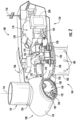
- the hub 110 may be rotatably coupled to an electric generator 118 ( FIG. 2 ) of an electrical system 150 ( FIG. 2 ) positioned within the nacelle 106 to permit electrical energy to be produced.
- the wind turbine 100 may also include a controller 200 centralized within the nacelle 106.
- the controller 200 may be located within any other component of the wind turbine 100 or at a location outside the wind turbine.
- the controller 200 may be communicatively coupled to any number of the components of the wind turbine 100 in order to control the components.
- the controller 200 may include a computer or other suitable processing unit.
- the controller 200 may include suitable computer-readable instructions that, when implemented, configure the controller 200 to perform various different functions, such as receiving, transmitting and/or executing wind turbine control signals.
- the generator 118 may be coupled to the rotor 108 for producing electrical power from the rotational energy generated by the rotor 108 when in operation.
- the rotor 108 may include a rotor shaft 122 coupled to the hub 110 for rotation therewith.
- the rotor shaft 122 may be rotatably supported by a main bearing 144.
- the rotor shaft 122 may, in turn, be rotatably coupled to a high-speed shaft 124 of the generator 118 through an optional gearbox 126 connected to a bedplate support frame 136 by one or more torque arms 142.
- the rotor shaft 122 may provide a low-speed, high-torque input to the gearbox 126 in response to rotation of the rotor blades 112 and the hub 110.
- the gearbox 126 may then be configured with a plurality of gears 148 to convert the low-speed, high-torque input to a high-speed, low-torque output to drive the high-speed shaft 124 and, thus, the generator 118.
- the gearbox 126 may be configured with multiple gear ratios so as to produce varying rotational speeds of the high-speed shaft for a given low-speed input, or vice versa.
- Each rotor blade 112 may also include a pitch control mechanism 120 configured to rotate the rotor blade 112 about its pitch axis 116.
- Each pitch control mechanism 120 may include a pitch drive motor 128 (e.g., any suitable electric, hydraulic, or pneumatic motor), a pitch drive gearbox 130, and a pitch drive pinion 132.
- the pitch drive motor 128 may be coupled to the pitch drive gearbox 130 so that the pitch drive motor 128 imparts mechanical force to the pitch drive gearbox 130.
- the pitch drive gearbox 130 may be coupled to the pitch drive pinion 132 for rotation therewith.
- the pitch drive pinion 132 may, in turn, be in rotational engagement with a pitch bearing 134 coupled between the hub 110 and a corresponding rotor blade 112 such that rotation of the pitch drive pinion 132 causes rotation of the pitch bearing 134.
- rotation of the pitch drive motor 128 drives the pitch drive gearbox 130 and the pitch drive pinion 132, thereby rotating the pitch bearing 134 and the rotor blade(s) 112 about the pitch axis 116.
- the wind turbine 100 may include one or more yaw drive mechanisms 138 communicatively coupled to the controller 200, with each yaw drive mechanism(s) 138 being configured to change the angle of the nacelle 106 relative to the wind (e.g., by engaging a yaw bearing 140 of the wind turbine 100).
- the wind turbine 100 may include an environmental sensor 156 configured for gathering data indicative of one or more environmental conditions.
- the environmental sensor 156 may be operably coupled to the controller 200.
- the environmental sensor(s) 156 may, for example, be a wind vane, an anemometer, a lidar sensor, thermometer, barometer, or any other suitable sensor.
- the data gathered by the environmental sensor(s) 156 may include measures of wind speed, wind direction, wind shear, wind gust, wind veer, atmospheric pressure, and/or temperature.
- the environmental sensor(s) 156 may be mounted to the nacelle 106 at a location downwind of the rotor 108.
- the environmental sensor(s) 156 may, in alternative embodiments, be coupled to, or integrated with, the rotor 108. It should be appreciated that the environmental sensor(s) 156 may include a network of sensors and may be positioned away from the turbine 100.
- the wind turbine 100 may include a at least one operational sensor 158.
- the operational sensor(s) 158 may be configured to detect a performance of the wind turbine 100 (e.g., in response to the environmental conditions).
- the operational sensor(s) 158 may be a rotational speed sensor operably coupled to the controller 200.
- the operational sensor(s) 158 may be directed at the rotor 108 of the wind turbine 100, the rotor shaft 122 of the wind turbine 100 and/or the generator 118.
- the operational sensor(s) 158 may gather data indicative of the rotational speed and/or rotational position of the rotor shaft 122, and thus the rotor 108 in the form of a rotor speed and/or a rotor azimuth.
- the operational sensor(s) 158 may, in an embodiment, be an analog tachometer, a D.C. tachometer, an A.C. tachometer, a digital tachometer, a contact tachometer a non-contact tachometer, or a time and frequency tachometer.
- the operational sensor(s) 158 may, for example, be an encoder, such as an optical encoder.
- the operational sensor(s) 158 may be configured to monitor the speed of the rotor 108 based on a passage of a rotating feature, such as a plurality of bolts securing the hub 110 to the rotor shaft 122.
- the operational sensor(s) 158 may be at least one accelerometer and/or position sensor coupled to the nacelle 106 and configured to detect a displacement from a nominal position thereof.
- the wind turbine may include a plurality of temperature sensors 180.
- the plurality of temperature sensors 180 may be distributed circumferentially about the vertical axis (V) of the wind turbine 100.
- the plurality of temperature sensors 180 may be operationally coupled to the tower 102 to detect a temperature thereof.
- the plurality of temperature sensors 180 may be positioned radially inward of an outer face of the tower 102.
- at least a portion of the plurality of temperature sensors 180 may be coupled to an inner face of the tower 102 and/or embedded, at least partially, within the tower wall 103.
- the plurality of temperature sensors 180 may be positioned radially outward of the tower wall. It should be appreciated that the plurality of temperature sensors 180 may include contact sensors and/or non-contact sensors.
- the plurality of temperature sensors 180 may include electro-mechanical, resistive and/or electronic sensors, such as thermistors, resistive temperature detectors, thermocouples, semiconductor junction sensors, infra-red sensors, thermal radiation sensors and/or combinations thereof.
- the term "monitor" and variations thereof indicates that the various sensors of the wind turbine 100 may be configured to provide a direct measurement of the parameters being monitored or an indirect measurement of such parameters.
- the sensors described herein may, for example, be used to generate signals relating to the parameter being monitored, which can then be utilized by the controller 200 to determine a condition or response of the wind turbine 100.
- the wind turbine 100 may be one of a plurality of wind turbines 162 of a wind farm 152 and the controller 200 may be configured as a farm controller.
- the wind farm 152 may include twenty-two wind turbines 100.
- the wind farm 152 may include any other number of wind turbines 100, such as less than twelve wind turbines 100 or greater than twelve wind turbines 100.
- the controller(s) 200 may be communicatively coupled via a wired connection, such as by connecting the controller(s) through suitable communicative links 154 (e.g., a suitable cable).
- the controller(s) may be communicatively coupled through a wireless connection, such as by using any suitable wireless communications protocol known in the art.
- FIGS. 4-11 multiple embodiments of a system 300 for controlling the wind turbine 100 according to the present disclosure are presented.
- the system 300 may include the controller 200 communicatively coupled to the operational sensor(s) 158 and/or environmental sensor(s) 156.
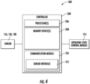
- the controller 200 includes one or more processor(s) 206 and associated memory device(s) 208 configured to perform a variety of computer-implemented functions (e.g., performing the methods, steps, calculations and the like and storing relevant data as disclosed herein).
- the controller 200 may also include a communications module 210 to facilitate communications between the controller 200, and the various components of the wind turbine 100.
- the communications module 210 may include a sensor interface 212 (e.g., one or more analog-to-digital converters) to permit signals transmitted from the sensor(s) 156, 158, 180 to be converted into signals that can be understood and processed by the processors 206.
- the sensor(s) 156, 158, 180 may be communicatively coupled to the communications module 210 using any suitable means.
- the sensor(s) 156, 158, 180 may be coupled to the sensor interface 212 via a wired connection.
- the senor(s) 156, 158, 180 may be coupled to the sensor interface 212 via a wireless connection, such as by using any suitable wireless communications protocol known in the art.
- the communications module 210 may also be operably coupled to an operating state control module 214 configured to change at least one wind turbine operating state.
- the term "processor” refers not only to integrated circuits referred to in the art as being included in a computer, but also refers to a controller, a microcontroller, a microcomputer, a programmable logic controller (PLC), an application specific integrated circuit, and other programmable circuits.
- the memory device(s) 208 may generally comprise memory element(s) including, but not limited to, computer readable medium (e.g., random access memory (RAM)), computer readable non-volatile medium (e.g., a flash memory), a floppy disk, a compact disc-read only memory (CD-ROM), a magneto-optical disk (MOD), a digital versatile disc (DVD) and/or other suitable memory elements.
- RAM random access memory
- CD-ROM compact disc-read only memory
- MOD magneto-optical disk
- DVD digital versatile disc
- Such memory device(s) 208 may generally be configured to store suitable computer-readable instructions that, when implemented by the processor(s) 206, configure the controller 200 to perform various functions including, but not limited to, determining a thermal gradient due to solar heating, determine a displacement of a reference point resulting from a thermal expansion, determining correction factor corresponding to the displacement, generating a set point for a component of the wind turbine, and establishing an operating state of the wind turbine based, at least in part, on the setpoint as described herein, as well as various other suitable computer-implemented functions.
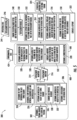
- the controller 200 may be configured to implement process 400 by to determine a thermal gradient 302 of the tower 102.
- the thermal gradient 302 may be indicative of the solar heating of the tower 102 for a given sun position 304.
- the thermal gradient 302 may be indicative of circumferential variations in the temperature of a tower wall 103 of the tower 102.
- the controller 200 may be configured to determine a displacement 306 of a reference point 308 of the wind turbine 100 from a nominal position 310.
- the displacement 306 may result from a thermal expansion of a portion 312 of the tower 102.
- the displacement may include a displacement magnitude 314 and a displacement direction 316.
- the displacement direction 316 may be in a radial direction (relative to a vertical axis (V) of the tower 102) that is opposite a location of a maximal peak 318 of the thermal gradient 302 on the tower 102.
- the controller 200 may also be configured to implement process 500 to determine a correction factor 320.
- the correction factor 320 may correspond to the displacement 306.
- the correction factor 320 may be configured to mitigate an impact of the displacement 306 resulting from the thermal expansion of the portion 312 of the tower 102.
- the controller 200 may also generate a setpoint 322 for a component 160 of the wind turbine 100.
- the setpoint 322 may be based, at least in part, on the correction factor 320.
- an operating state 324 of the wind turbine 100 may be established based, at least in part, on the setpoint 322.
- the controller 200 may, in an embodiment, determine a temperature differential 326 between a shadowed face 328 of the tower 102 and an exposed face 330 of the tower 102 as indicated by the thermal gradient 302.
- the difference in temperature between the shadowed face 328 and the exposed face 330 may result in differing expansions of the corresponding portions of the tower wall 103.
- the exposed face 330 may be defined by an arc 340 extending either side of the azimuth 342 of the sun at a given instant.
- the portion of the tower 102 covered by the arc 340 at the given instant may be illuminated by the sun and, therefore, subjected to solar heating due to solar radiation, while the portion of the tower 102 following outside of the arc 340 may be shadowed.
- the controller 200 may determine an increase 332 in a height of the exposed face 330.
- the increase 332 in height may be determined based on a coefficient of thermal expansion of a tower material (e.g., the material of the tower wall 103) and the temperature differential 326. It should be appreciated that the temperature of the tower wall 103 due to solar heating may be greater (as indicated by the maximal peak 318 of the thermal gradient 302) on the exposed face 330 than on the shadowed face 328. Accordingly, the portion of the tower wall 103 corresponding to the exposed face 330 may expand to a greater degree than the portion of the tower wall 103 corresponding to the shadowed face 328. As such, the displacement magnitude 314 may be based, at least in part, on the increase 332 in the height.
- the tower 102 may include a plurality of vertically arranged tower segments 164.
- the tower segment(s) 164 may have a generally cylindrical or frustum-shaped structure.
- the tower segment(s) 164 may include a generally horizontal upper face 166 and a generally horizontal lower face 168 when in a nominal orientation 170 (e.g., when not subjected to uneven thermal expansion).
- the distance between the generally horizontal upper face 166 and the generally horizontal lower face 168 may define a nominal height (Hi) of the tower segment(s) 164.
- Hi nominal height
- the upper face 166 and/or the lower face 168 may depart the nominal orientation 170 and establish a displaced orientation 172.
- the height (H2) of the exposed face 330 when in the displaced orientation 172 the height (H2) of the exposed face 330 may increase to a greater degree than the height of the shadowed face 328, which may remain at essentially the nominal height (Hi) resulting in the upper face 166 and/or the lower face 168 having a canted orientation relative to horizontal. It should be appreciated that the difference between the height (H2) of the exposed face 330 when displaced and a nominal height (Hi) may correspond to the increase 332 in the height exposed face 330 and, therefore, the displacement magnitude 314 of the reference point 308 due to solar heating.
- the plurality of vertically arranged tower segments 164 may be a plurality of virtual tower segments 164.
- the tower 102 may be a unitary structure (e.g., having a single segment extending between the support surface 104 and the nacelle 106)
- the tower 102 may be mathematically divided into a plurality of virtual tower segments 164.
- the plurality of vertically arranged tower segments 164 be subdivided into the plurality of virtual tower segments 164. It should be appreciated that the employment of virtual tower segments 164 may, in an embodiment, facilitate the determination of the increase 332 in the height of the exposed face 330.
- the controller 200 may determine the increase 332 in the height of the exposed face 330 of the tower 102 by determining the temperature differential 326 for each tower segment 164 of the plurality of tower segments 164. Based on the temperature differential 326 for each tower segment 164, the controller 200 may, as depicted at 336, determine an increase 332 in height of an exposed face 330 of each tower segment 164 of the plurality of segments 164. As is further depicted at 338, the controller 200 may then combine the increase 332 in height of the exposed face 330 of each tower segment 164 of the plurality of tower segments 164 to determine the increase 332 in height of the exposed face 330 of the tower 102.
- the displacement magnitude 314 may be proportional to the increase 332 in the height of the exposed face 330 of the tower 102. For example, a greater increase 332 in the height of the exposed face 330 of the tower 102 may result in a higher displacement magnitude 314 of the reference point 308 than may result from a lesser increase 332, such as may be encountered when the temperature differential 326 is minimal.
- the system 300 may utilize the plurality of temperature sensors 180 in the determination of the thermal gradient 302. Accordingly, a plurality of temperature indications 402 may be received from the plurality of temperature sensors 180. Each of the plurality of temperature indications 402 may correspond to a tower temperature at the location of each temperature sensor 180.
- the thermal gradient 302 may be a circumferential thermal gradient 302 that is based on the plurality of temperature indications 402 received from the plurality of temperature sensors 180.
- each temperature sensor 180 of the plurality of temperature sensor 180 may correspond to the sensed location of the tower rather than the physical location of a body of the temperature sensor 180.
- the location of each temperature sensor 180 may refer to the portion of the tower 102 at which a sensing element of the temperature sensor(s) 180 is directed, aimed, or oriented.
- a first portion 404 of the plurality of temperature sensors 180 may, in an embodiment, be operably coupled to the shadowed face 328. Additionally, a second portion 406 of the plurality of temperature sensors 180 may be operably coupled to the exposed face 330. It should be appreciated that the number of temperature sensors 180 of the second portion 406 may be greater than or equal to the number of temperature sensors 180 of the first portion 404. It should further be appreciated that the particular temperature sensors 180 of the plurality of temperature sensors 180 included within the first portion 404 and the second portion 406 may vary as the azimuth to the sun position 304 advances across the sky. For example, a temperature sensor 180 may be coupled to the shadowed face 228 in the morning but may be illuminated by the sun at noon. Therefore, the temperature sensor 180 may transition from the second portion 406 to the first portion 404.
- the temperature indications 402 may, in an embodiment, be utilized by the controller to determine the temperature differential 326.
- the controller 200 may determine a shadowed-face temperature 408 for the shadowed face 328.
- the shadowed-face temperature 408 may be based on an average of the temperature indications 402 from each temperature sensor 180 of the first portion 404 of the plurality of temperature sensors 180 at a given instant.
- the controller 200 may, in an embodiment, determine a maximal temperature indication 410 of the second portion 406 of the plurality of temperature sensors 180 at the given instant. The controller 200 may then determine an exposed-face temperature 412 for the exposed face 330. The exposed-face temperature 412 may be based, at least in part, on the maximal temperature indication 410. The exposed-face temperature 412 may correspond to a designated percentage 414 of the maximal temperature indication 410. As such, the exposed-face temperature 412 may be less than or equal to the maximal temperature indication 410. The controller 200 may, in an embodiment, subtract the shadowed-face temperature 408 from the exposed-face temperature 412 to determine the temperature differential 326 between the shadowed face 328 of the tower 102 and the exposed face 330 of the tower.
- the maximal temperature indication 410 may represent the temperature of a relatively small portion the exposed face 330, with the remainder (e.g., the majority) of the area of the exposed face 330 having a lesser temperature. As such the remainder of the exposed face 330 may exhibit less thermal expansion than would be projected/anticipated based on the maximal temperature indication 410. Insofar as the entirety of the exposed face 330 may not exhibit the degree of thermal expansion exhibited by the portion of the exposed face 330 corresponding to the maximal temperature indication 410, the utilization a percentage of the maximal temperature indication 410 as the exposed-face temperature 412 may improve the accuracy of the determination of the displacement magnitude 314.
- Determining the temperature differential 326 via the process 400 may, in an embodiment, include receiving a plurality of historical environmental observations 416.
- the plurality of historical environmental observations 416 may be received at a plurality of sampling intervals 418.
- the plurality of sampling intervals 418 may be indicative of a date and a time of day.
- the plurality of historical environmental observations 416 may, in various embodiments, include indications of ambient temperature, precipitation level, and/or cloud cover. It should be appreciated that the plurality of historical environmental observations 416 may be correlated to a given sun position 304 at the indicated date and time of day.
- the controller 200 may, in an embodiment, receive a plurality of historical temperature indications 420 for the tower 102 at the plurality of sampling intervals 418.
- the plurality of historical temperature indications 420 may, for example, be a plurality of temperature indications 402 received from the plurality of thermal sensors 180. However, it should be appreciated that the plurality of historical temperature indications 420 may be recorded from any other suitable sensing means. In an embodiment, the plurality of historical temperature indications 420 may be received as a plurality of historical thermal gradients.
- the controller 200 may determine an environmental-tower temperature correlation 422.
- the environmental-tower temperature correlation 422 may be indicative of a response of the tower 102 to the environmental conditions affecting the wind turbine 100 at a given time.
- the environmental-tower temperature correlation 422 may indicate that a particular thermal gradient 302 (e.g., an exposed-based temperature 412 and a shadowed-based temperature 408) is developed whenever the environmental conditions correspond to a particular ambient temperature and cloud cover during daylight hours.
- the environmental-tower temperature correlation 422 may be a lookup table, a graphical representation, a computer-implemented function, and/or a combination thereof.
- the controller 200 may be configured to receive current environmental data 424, which may include an environmental observation at the current date and time.
- the controller 200 may, as indicated at 426, then determine the temperature differential 326 based on the environmental-tower temperature correlation 422 and the environmental observation at the current date and time.
- the controller 200 may leverage the various recorded responses of the tower 102 to various historical environmental observations 416 to determine a current response (e.g., the temperature differential 326) of the tower 102 to the currently prevailing environmental conditions.
- utilizing the environmental-tower temperature correlation 422 to determine the current temperature differential 326 of the tower 102 may facilitate the utilization of a current environmental observation (from the current environmental data 424) to determine the current displacement magnitude 314 of the reference point 308.
- the displacement direction 316 may be in a radial direction opposite the location of the maximal peak 318 of the thermal gradient 302 on the tower 102.
- the location of the maximal peak 318 for a given sun position 304 may be identified by determining the thermal gradient 302 for the given sun position 304.
- determining the thermal gradient 302 may include determining both the contours of thermal gradient 302 indicative of the temperature variations of the tower 102 and the orientation of the thermal gradient 302 relative to the tower. It should be appreciated that the orientation of the thermal gradient 302 may rotate about the vertical axis (V) of the tower 102 in response to changes in the sun position 304 during daylight hours.
- the controller 200 may, in an embodiment, determine the azimuth angle 342 of the sun relative to the wind turbine 100 for a given sun position 304. As depicted at 428, the controller 200 may then determine the thermal gradient 302 based, at least in part, on the azimuth angle 342 of the sun. It should however be appreciated that the maximal peak 318 of the thermal gradient 302, and thus the displacement direction 316 may not be aligned with the azimuth angle 342 of the sun.
- the maximal peak 318 may lag the azimuth angle 342 of the sun as the sun advances across the sky (e.g., along the sun path (SP)) during daylight hours.
- the circumferential position 436 of the maximal peak 318 of the thermal gradient 302 may also be affected by the elevation angle 430 of the sun.
- the elevation angle 430 of the sun may influence the angle at which the solar radiation impacts the generally vertical surface of the tower 102.
- the angle at which the solar radiation impacts the tower 102 may, in turn, affect the rate at which the temperature of the impacted portion of the exposed face 330 increases due to solar heating.
- the different elevation angles 430 of the sun in the winter and summer months may result in differing impact angles of the solar radiation on the tower 102.
- the sun may have a lower elevation angle 430 than in the summer months.
- the solar radiation may impact the tower 102 at an angle that is more perpendicular in the winter months than in the summer months the more direct impact of the solar radiation in the winter months may result in the relatively rapid heating of the portion of the exposed face 330 lying along the azimuth to the sun.
- the less direct impact of the solar radiation in the summer months may result in a slower heating of the portion of the exposed face 330, resulting in a greater deviation between the azimuth angle 342 of the sun and the circumferential position 436 the maximal peak 318 during the summer months than during the winter months.
- the process 400 of the system 300 may include determining the elevation angle 430 of the sun above the horizon relative to the wind turbine 100 for the given sun position 304.
- the controller 200 may then determine an azimuth offset 432 for the thermal gradient 302.
- the azimuth offset 432 may be based, at least in part, on the elevation angle 430.
- the azimuth offset 432 may be proportional to the secant of the elevation angle 430.
- the azimuth offset 432 may correspond to an angular difference between the azimuth angle 342 of the sun and an azimuth angle 434 of the location of the maximal peak 318 of thermal gradient 302 on the tower 102. It should be appreciated that the azimuth offset 432 may reflect an angular distance traversed by the sun in the amount of time that may elapse (e.g., a delay) between the instant the azimuth angle 342 of the sun intersects a particular portion of the exposed face 330 and the instant that the maximal peak 318 of the thermal gradient 302 is located at the particular portion of the exposed face 330. For example, as depicted in FIG.
- the sun position 304 may correspond with position Si the instant the azimuth angle 342 of the sun intersects the particular portion of the exposed face 330 but may have advanced along the sun path (SP) to position S2 by the time the maximal peak 318 of the thermal gradient 302 is established at the particular position.
- the azimuth offset 432 may reflect the degree to which the azimuth angle 434 of the location of the maximal peak 318 (thus the displacement direction 316) may lag (e.g., temporally lag) the azimuth angle 342 of the sun. It should also be appreciated that the azimuth offset 432 may vary with the latitude of the wind turbine 100, time of year, and/or time of day.
- the controller 200 may determine the circumferential position 436 of the maximal peak 318 of the thermal gradient 302.
- the determination of the circumferential position 436 may be based on azimuth offset 432.
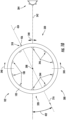
- the circumferential position 436 of the maximal peak 318 may, for example as depicted in FIG. 9 , be expressed in terms of degrees from east and/or a point of intersection of the sun with the horizon.
- the circumferential position 436 may also be expressed in other suitable terms such as degrees or radians from due north or a coordinate system defined by the tower 102.
- the controller 200 may, in an embodiment, receive an indication of the thermal property of a tower material (e.g., a material of the tower wall 103). The controller 200 may then determine the azimuth offset 432 for the thermal gradient 302 based, at least in part, on the thermal property of the tower material. For example, in an embodiment wherein the thermal properties of tower material facilitate a rapid rise in temperature when subjected to solar heating, the azimuth offset 432 may be smaller than for a tower material that resists temperature change.
- the controller 200 of the system 300 may be configured to determine the correction factor 320.
- the correction factor 320 may be configured to mitigate an impact of the displacement 306 on an operation (e.g., at least one control setpoint) of the wind turbine 100.
- the controller 200 may, in an embodiment implementing the process 500, receive a plurality of historical positional observations 502 of the sun at a plurality of sampling intervals 418.
- the controller 200 may determine the thermal gradient 302 of the tower 102 at each of the historical positional observations 502.
- the determination of the thermal gradient 302 of the tower 102 at each of the historical positional observations 502 may, for example, be based on temperature indications 402 (e.g. historical temperature indications 420) received from the plurality of thermal sensors 180.
- the controller 200 may then determine a sun-gradient correlation 506.
- the sun-gradient correlation 506 may describe a relationship between the plurality of historical positional observations 502 and the location of the maximal peak 318 (e.g., the circumferential position 436) of the thermal gradient 302 at each of the historical positional observations 502.
- the controller 200 may utilize the historical data to determine that for a particular sun position 304 (e.g., azimuth angle 342 and elevation angle 430), the maximal peak 318 may have a particular circumferential position 436.
- the sun-gradient correlation 506 may be a lookup table, a graphical representation, a computer-implemented function, and/or a combination thereof.
- the controller 200 may utilize the sun-gradient correlation 506 to determine a current and/or projected location of the maximal peak 318.
- the controller 200 may receive a current sun position 510 or a projected sun position 512 (e.g., current and/or projected azimuth angle 342 and elevation angle 430).
- the location of the maximal peak 318 of the thermal gradient 302 may be determined as indicated by the sun-gradient correlation 506 when the sun is in one of the current position 510 or the projected position 512.
- the controller 200 may determine the displacement 306 of the reference point 308 based on the current sun position 510 and/or the projected sun position 512.
- the correction factor 320 may then be determined based, at least in part, on the displacement 306 of the reference point 308 for the current sun position 510 and/or the projected sun position 512.
- the current sun position 510 may be utilized by the controller 200 to determine the correction factor 320 in order to facilitate the real-time control of the wind turbine 100.
- the controller 200 may utilize the projected sun position 512 to model a potential correction factor 320 for various future periods of operation, such as various time increments during daylight operations of the wind turbine 100 on a particular day.
- determining the current and/or potential correction factor 320 corresponding to the current sun position 510 and/or the projected sun position 512 may be based, at least in part, on a current displacement magnitude 518 and/or a projected displacement magnitude 520.
- the controller 200 may, in an embodiment, receive the plurality of historical environmental observations 416 at the plurality of sampling intervals 418. The controller 200 may then determine the environmental-tower temperature correlation 422 between the plurality of historical environmental observations 416 and the corresponding plurality of historical temperature indications 420 for the tower 102 at the plurality of sampling intervals 418.
- the controller 200 may determine the temperature differential 326 (e.g., a current and/or projected temperature differential 326) based on the environmental-tower temperature correlation 422 and a current environmental observation 522 and/or a forecast environmental condition 526.
- the current environmental observation 522 may be at least a portion of the current environmental data 424, which may include an environmental observation at the current date and time received from the environmental sensor(s) 156.
- the controller 200 may determine the current displacement magnitude 518 and/or the projected displacement magnitude 520 at the current environmental observation 524 and/or the forecast environmental condition 526. In other words, the controller 200 may determine the current and/or projected displacement magnitude 518, 520 resulting from the corresponding environmental condition. The correction factor 320 may then be determined and configured to mitigate the impact of the current/projected displacement magnitude 518, 520 on the operation of the wind turbine 100.
- the controller 200 may be configured to receive environmental data 424 (e.g., a current environmental observation 524) descriptive of a wind affecting the wind turbine 100.
- the environmental data 424 may include a wind direction and a wind magnitude (e.g., a wind velocity).
- the controller 200 may, as depicted at 528, determine an orientation of the wind relative to the location (, e.g., the circumferential position 436) of the maximal peak 318 of the thermal gradient 302.
- the controller 200 may, as depicted at 530, determine an impact of the wind on the displacement magnitude 316. Specifically, the controller 200 may, in an embodiment, determine an impact on displacement magnitude 316 of the displacement 306 of the reference point 308 resulting from the thermal expansion. In other words, the controller 200 may, for example, determine whether the wind direction and magnitude result in an increase or decrease of the displacement magnitude 316 relative to such displacement magnitude 316 as may be attributable solely to the thermal expansion.
- the controller 200 may, in an embodiment, generate a modified correction factor 532.
- the modified correction factor 532 may mitigate/eliminate the impact of the wind on the displacement magnitude 316 such that the true value of the displacement magnitude 314 attributable to thermal expansion may, therefore, be corrected for by the system 300.
- the controller 200 may, in an embodiment, receive operational data 344, such as from the operational sensor(s) 158.
- the operational data 344 may be indicative of a displacement vector 346 of the reference point 308.
- the displacement vector 346 may include magnitude and direction components that may be attributable to thermal expansion due to solar heating, the wind affecting the wind turbine 100, operations of the wind turbine 100 and/or combinations thereof.
- the displacement vector 346 may represent an apparent displacement of the reference point 308.
- the displacement vector 346 may correspond to positional data and/or acceleration data received from the operational sensor(s) 158.
- the controller 200 may, in an embodiment, combine the displacement vector 346 and the modified correction factor 532 to generate a displacement variable 350.
- the displacement variable 350 may be indicative of a response of the tower 102 to a factor other than solar heating.
- the displacement variable 350 may be indicative of a response of the wind turbine 100 to the wind.
- the modified correction factor 532 to the displacement vector 346 the impact of solar heating on the perceived displacement of the reference point 308 may be mitigated/eliminated and the modified displacement vector 346 may then be indicative of a response of the wind turbine 100 to the prevailing wind.
- the displacement variable 350 may be a control input upon which control of the wind turbine 100 may, at least in part, be based in order to establish the wind turbine 100 at an optimal setpoint for the prevailing wind/grid conditions. Accordingly, as depicted at 352, in an embodiment, the controller 200 may determine the setpoint 322 for the component 160 of the wind turbine 100 based, at least in part, on the displacement variable. In other words, the utilization of the displacement variable 350 may facilitate control decisions based on the displacement of the reference point 308 without the control decision being impacted by the displacement magnitude 314 due to solar heating.
- the controller 200 may determine an indicated three-axis coordinate 354 for the reference point 308.
- the three-axis coordinate 354 may, for example, correspond to positional data received from the operational sensor(s) 158.
- the indicated three-axis coordinate 354 may represent a displaced position of the reference point 308 in response to solar heating, the wind, and/or an operation of the wind turbine 100.
- the indicated three-axis coordinate 354 may not accurately reflect a degree of deviation of an operation of the wind turbine 100 from an optimal setpoint for the given wind conditions.
- the indicated three-axis coordinate 354 may include the displacement magnitude 316 resulting from solar heating and the displacement magnitude resulting from the wind (or an operation in response thereto)
- the indicated three-axis coordinate 354 may correspond to a thrust level on the wind turbine 100 that is different than the thrust truly exerted on the wind turbine 100.
- controlling the wind turbine 100 based on the indicated three-axis coordinate 354 may, for example, result in generating less power than would otherwise be possible for the given wind conditions or potentially overloading a component 160 of the wind turbine 100.
- the controller 200 may, in an embodiment, determine a wind-affected, three-axis coordinate 356 for the reference point 308.
- the wind-affected, three-axis coordinate 356 may be based on the indicated three-axis coordinate 354 and the correction factor 320.
- the wind-affected, three-axis coordinate 356 may be indicative of a displacement of the reference point 308 due to the wind and/or an operation of the wind turbine 100 in response to the wind in the absence of the displacement magnitude 314 attributable to solar heating.
- the wind-affected, three-axis coordinate 356 may indicate the displacement of the wind turbine 100 to be utilized as a control input for establishing the wind turbine 100 at an optimal setpoint for the given wind conditions. Accordingly, as depicted at 358, the controller 200 may determine the setpoint 322 for the component 160 of the wind turbine 100 based, at least in part, on the wind-affected, three-axis coordinate 356.
- FIG. 12 a flow diagram of one embodiment of a method 600 for controlling a plurality of wind turbines 162 of the wind farm 152 is illustrated.
- the plurality of wind turbines 162 may include a designated turbine 174 having the nacelle 106 mounted atop the tower 102.
- the method 600 may be implemented using, for instance, the system 300 discussed above with reference to FIGS. 4-11 .
- FIG. 12 depicts steps performed in a particular order for purposes of illustration and discussion. Those of ordinary skill in the art, using the disclosures provided herein, will understand that various steps of the method 600 or any of the other methods disclosed herein may be adapted, modified, rearranged, performed simultaneously or modified in various ways without deviating from the scope of the present disclosure.
- the method 600 may include determining, via a controller, a thermal gradient of the tower of the designated turbine due to solar heating for a given sun position.
- the method 600 may include determining, via the controller, a displacement of a reference point of the designated turbine from a nominal position resulting from a thermal expansion of a portion of the tower.
- the displacement may include a displacement magnitude and a displacement direction.
- the displacement direction may be in a radial direction opposite a location of a maximal peak of the thermal gradient on the tower.
- the method 600 may include determining, via the controller, a correction factor corresponding to the displacement.
- the correction factor may be configured to mitigate an impact of the displacement resulting from the thermal expansion of the portion of the tower.
- the method 600 may include implementing, via the controller, the correction factor at each additional wind turbine of the plurality of wind turbines. Also, as shown at (610), the method 600 may include determining, via the controller, a setpoint for a component of each wind turbine of the plurality of wind turbines based, at least in part, on the correction factor. Further, as shown at (612), the method 600 may include establishing an operating state of each wind turbine of the plurality of wind turbines based, at least in part, on the setpoint.
Landscapes
- Engineering & Computer Science (AREA)
- Life Sciences & Earth Sciences (AREA)
- Sustainable Development (AREA)
- Sustainable Energy (AREA)
- Chemical & Material Sciences (AREA)
- Combustion & Propulsion (AREA)
- Mechanical Engineering (AREA)
- General Engineering & Computer Science (AREA)
- Wind Motors (AREA)
Abstract
Description
- The present disclosure relates in general to wind turbines, and more particularly to systems and methods for controlling wind turbines in the presence of solar heating.
- Wind power is considered one of the cleanest, most environmentally friendly energy sources presently available, and wind turbines have gained increased attention in this regard. A modern wind turbine typically includes a tower, a generator, a gearbox, a nacelle, and one or more rotor blades. The nacelle includes a rotor assembly coupled to the gearbox and to the generator. The rotor assembly and the gearbox are mounted on a bedplate support frame located within the nacelle. The one or more rotor blades capture kinetic energy of wind using known airfoil principles. The rotor blades transmit the kinetic energy in the form of rotational energy so as to turn a shaft coupling the rotor blades to a gearbox, or if a gearbox is not used, directly to the generator. The generator then converts the mechanical energy to electrical energy and the electrical energy may be transmitted to a converter and/or a transformer housed within the tower and subsequently deployed to a utility grid. Modern wind power generation systems typically take the form of a wind farm having multiple such wind turbine generators that are operable to supply power to a transmission system providing power to an electrical grid.
- In certain instances, the capturing of the kinetic energy of the wind by the rotor blades may result in a displacement of the nacelle from a neutral position. As operational controls of the wind turbines become more sensitive, the displacement of the nacelle may be employed in the generation of various setpoint commands. Accordingly, in order to accurately control the wind turbine, it may be desirable to differentiate a nacelle displacement resulting from an operation of the wind turbine from a nacelle displacement resulting from other factors.
- Thus, the art is continuously seeking new and improved systems and methods that address the aforementioned issues relating to the displacement of the nacelle. As such, the present disclosure is directed to systems and methods for controlling a wind turbine in the presence of solar heating.
- Aspects and advantages of the invention will be set forth in part in the following description, or may be obvious from the description, or may be learned through practice of the invention.
- In one aspect, the present disclosure is directed to a method for controlling a wind turbine. The wind turbine may have a nacelle mounted atop the tower. The method may include determining, via a controller, a thermal gradient of the tower due to solar heating for a given sun position. The controller may then determine a displacement of a reference point of the wind turbine from a nominal position resulting from a thermal expansion of a portion of the tower. The displacement may include a displacement magnitude and a displacement direction, and the displacement direction may be in a radial direction opposite a location of a maximal peak of the thermal gradient on the tower. The method may also include determining, via the controller, a correction factor corresponding to the displacement, wherein the correction factor is configured to mitigate an impact of the displacement resulting from the thermal expansion of the portion of the tower. Additionally, the method may include generating, via the controller, a setpoint for a component of the wind turbine based, at least in part, on the correction factor. Further, the method may include establishing an operating state of the wind turbine based, at least in part, on the setpoint.
- In another aspect, the present disclosure is directed to a method for controlling a plurality of wind turbines of a wind farm. The plurality of wind turbines may include a designated turbine having a nacelle mounted atop a tower. The method may include determining, via a controller, a thermal gradient of the tower of the designated turbine due to solar heating for a given sun position. The controller may also determine a displacement of a reference point of the designated turbine from a nominal position resulting from a thermal expansion of a portion of the tower. The displacement may include a displacement magnitude and a displacement direction, with the displacement direction being in a radial direction opposite a location of a maximal peak of the thermal gradient on the tower. The controller may also determine a correction factor corresponding to the displacement. The correction factor may be configured to mitigate an impact of the displacement resulting from the thermal expansion of the portion of the tower. The method may also include implementing, via the controller, the correction factor at each additional wind turbine of the plurality of wind turbines and determining, via the controller, a setpoint for a component of each wind turbine of the plurality of wind turbines based, at least in part, on the correction factor. Additionally, the method may include establishing an operating state of each wind turbine of the plurality of wind turbines based, at least in part, on the setpoint.
- In another aspect, the present disclosure is directed to a system for controlling a wind turbine. The system may include a tower having a plurality of vertically arranged tower segments and a nacelle mounted atop the tower. Additionally, the system may include a controller. The controller may include at least one processor configured to perform a plurality of operations. The plurality of operations may include any of the operations and/or features described herein.
- These and other features, aspects and advantages of the present invention will become better understood with reference to the following description and appended claims. The accompanying drawings, which are incorporated in and constitute a part of this specification, illustrate embodiments of the invention and, together with the description, serve to explain the principles of the invention.
- A full and enabling disclosure of the present invention, including the best mode thereof, directed to one of ordinary skill in the art, is set forth in the specification, which makes reference to the appended figures, in which:
-
FIG. 1 illustrates a perspective view of one embodiment of a wind turbine according to the present disclosure; -
FIG. 2 illustrates a perspective, internal view of one embodiment of a nacelle of the wind turbine according to the present disclosure; -
FIG. 3 illustrates a schematic diagram of one embodiment of a wind farm having a plurality of wind turbines according to the present disclosure; -
FIG. 4 illustrates a block diagram of one embodiment of a controller for use with the wind turbine according to the present disclosure; -
FIG. 5 illustrates a flow diagram of one embodiment of a control logic of a system for controlling a wind turbine according to the present disclosure; -
FIG. 6 illustrates a flow diagram of one embodiment of a portion of the control logic ofFIG. 5 according to the present disclosure; -
FIG. 7 illustrates a flow diagram of one embodiment of a portion of the control logic ofFIG. 5 according to the present disclosure; -
FIG. 8 illustrates a perspective view of a wind turbine tower subjected to solar heating according to the present disclosure; -
FIG. 9 illustrates an overhead view of the tower ofFIG. 8 particularly illustrating a displacement of a reference point positioned at the tower top relative to the tower base according to the present disclosure; -
FIG. 10 illustrates a horizontal cross-sectional view of a portion of the wind turbine tower according to the present disclosure; -
FIG. 11 illustrates a perspective view of a portion of the wind turbine tower according to the present disclosure; and -
FIG. 12 illustrates a flow chart of one embodiment of a method for controlling a plurality of wind turbines of a wind farm. - Repeat use of reference characters in the present specification and drawings is intended to represent the same or analogous features or elements of the present invention.
- Reference now will be made in detail to embodiments of the invention, one or more examples of which are illustrated in the drawings. Each example is provided by way of explanation of the invention, not limitation of the invention. In fact, it will be apparent to those skilled in the art that various modifications and variations can be made in the present invention without departing from the scope or spirit of the invention. For instance, features illustrated or described as part of one embodiment can be used with another embodiment to yield a still further embodiment. Thus, it is intended that the present invention covers such modifications and variations as come within the scope of the appended claims and their equivalents.
- As used herein, the terms "first", "second", and "third" may be used interchangeably to distinguish one component from another and are not intended to signify location or importance of the individual components.
- The terms "coupled," "fixed," "attached to," and the like refer to both direct coupling, fixing, or attaching, as well as indirect coupling, fixing, or attaching through one or more intermediate components or features, unless otherwise specified herein.
- Approximating language, as used herein throughout the specification and claims, is applied to modify any quantitative representation that could permissibly vary without resulting in a change in the basic function to which it is related. Accordingly, a value modified by a term or terms, such as "about", "approximately", and "substantially", are not to be limited to the precise value specified. In at least some instances, the approximating language may correspond to the precision of an instrument for measuring the value, or the precision of the methods or machines for constructing or manufacturing the components and/or systems. For example, the approximating language may refer to being within a 10 percent margin.
- Here and throughout the specification and claims, range limitations are combined and interchanged, such ranges are identified and include all the sub-ranges contained therein unless context or language indicates otherwise. For example, all ranges disclosed herein are inclusive of the endpoints, and the endpoints are independently combinable with each other.
- Generally, the present disclosure is directed to systems and methods for controlling a wind turbine and/or wind farm in the presence of solar heating as the consequences of solar heating may affect the control systems implemented by the wind turbine. More specifically, for certain control systems implemented by wind turbines, the displacement of the nacelle from a nominal position may be an important control input variable. Accordingly, it may be desirable to account/correct for displacements of the nacelle which may stem from causes other than the operation of the wind turbine.
- For example, the displacement of the nacelle due to the operation of the wind turbine may be utilized to determine a performance of the wind turbine in order to determine whether various controllable properties (e.g., pitch, yaw, and/or generator torque setpoints) of the turbine are optimized for current wind conditions. If the displacement due to other causes is in the same direction as the displacement of interest, then the combined displacement may indicate to the controller a performance that is greater than the actual performance. Similarly, if the displacement due to other causes opposes the displacement of interest, then the combined displacement may indicate to the controller that the performance is less than the actual performance. Either scenario may result in the controller operating the wind turbine in a sub-optimal manner for the given wind conditions. Therefore, mitigating the impact of the displacement due to other causes may increase the alignment of the wind turbine controller setpoints to nominal setpoints for the given wind conditions, thereby improving the power output and/or life expectancy of the wind turbine/wind farm.
- One such displacement due to other causes may stem from uneven solar heating of the tower of the wind turbine. For example, during daylight hours, an exposed face of the wind turbine may be subjected to direct sunlight while a non-exposed face of the tower may be in a shadow generated by the tower itself. As a result, the exposed face may be heated to a greater extent than the portion of the tower that is in shadow. Accordingly, the exposed face may experience a greater degree of thermal expansion than the shadowed face. The thermal expansion of the exposed face may result in an increase in height of the exposed face, while the height of the shadowed face remains relatively unchanged. The resultant height differential between the exposed face and shadowed face may lead to the development of a bend in the tower, which may be evidenced by a displacement of a reference point.
- It should be appreciated that the direction of the bend may be oriented opposite the portion of the tower subjected to the maximal thermal heating (e.g., a maximal peak of a thermal gradient on the tower) at any given time. It should also be appreciated that the severity of the bend (e.g., the magnitude of the displacement of the reference point) may be influenced by the amount of solar heating of the exposed face and the coefficient of thermal expansion of the tower material. For example, the amount of solar heating, and/or the focus/concentration thereof, may be impacted by the elevation of the sun above the horizon, and therefore, the season.
- The systems and methods disclosed herein may be utilized to determine a thermal gradient of the tower due to solar heating. Determining the thermal gradient may include determining the location of a maximal peak of the thermal gradient and/or the magnitude thereof. Based on the thermal gradient, the systems may facilitate the determination of both a displacement magnitude and a displacement direction resulting from the solar heating. A correction factor may then be determined so as to mitigate an impact of the displacement. The correction factor may be used to establish a setpoint for a component of the wind turbine and, thus, an operating state of the wind turbine may be established.
- Referring now to the drawings,
FIG. 1 illustrates a perspective view of one embodiment of awind turbine 100 according to the present disclosure. As shown, thewind turbine 100 generally includes atower 102 extending from asupport surface 104, anacelle 106, mounted on thetower 102, and arotor 108 coupled to thenacelle 106. Therotor 108 includes arotatable hub 110 and at least onerotor blade 112 coupled to and extending outwardly from thehub 110. For example, in the illustrated embodiment, therotor 108 includes threerotor blades 112. However, in an alternative embodiment, therotor 108 may include more or less than threerotor blades 112. Eachrotor blade 112 may be spaced about thehub 110 to facilitate rotating therotor 108 to enable kinetic energy to be transferred from the wind into usable mechanical energy, and subsequently, electrical energy. For instance, thehub 110 may be rotatably coupled to an electric generator 118 (FIG. 2 ) of an electrical system 150 (FIG. 2 ) positioned within thenacelle 106 to permit electrical energy to be produced. - The
wind turbine 100 may also include acontroller 200 centralized within thenacelle 106. However, in other embodiments, thecontroller 200 may be located within any other component of thewind turbine 100 or at a location outside the wind turbine. Further, thecontroller 200 may be communicatively coupled to any number of the components of thewind turbine 100 in order to control the components. As such, thecontroller 200 may include a computer or other suitable processing unit. Thus, in several embodiments, thecontroller 200 may include suitable computer-readable instructions that, when implemented, configure thecontroller 200 to perform various different functions, such as receiving, transmitting and/or executing wind turbine control signals. - Referring now to
FIG. 2 , a simplified, internal view of one embodiment of thenacelle 106 of thewind turbine 100 shown inFIG. 1 is illustrated. As shown, thegenerator 118 may be coupled to therotor 108 for producing electrical power from the rotational energy generated by therotor 108 when in operation. For example, as shown in the illustrated embodiment, therotor 108 may include arotor shaft 122 coupled to thehub 110 for rotation therewith. Therotor shaft 122 may be rotatably supported by amain bearing 144. Therotor shaft 122 may, in turn, be rotatably coupled to a high-speed shaft 124 of thegenerator 118 through anoptional gearbox 126 connected to abedplate support frame 136 by one ormore torque arms 142. As is generally understood, therotor shaft 122 may provide a low-speed, high-torque input to thegearbox 126 in response to rotation of therotor blades 112 and thehub 110. Thegearbox 126 may then be configured with a plurality of gears 148 to convert the low-speed, high-torque input to a high-speed, low-torque output to drive the high-speed shaft 124 and, thus, thegenerator 118. In an embodiment, thegearbox 126 may be configured with multiple gear ratios so as to produce varying rotational speeds of the high-speed shaft for a given low-speed input, or vice versa. - Each
rotor blade 112 may also include apitch control mechanism 120 configured to rotate therotor blade 112 about itspitch axis 116. Eachpitch control mechanism 120 may include a pitch drive motor 128 (e.g., any suitable electric, hydraulic, or pneumatic motor), apitch drive gearbox 130, and apitch drive pinion 132. In such embodiments, thepitch drive motor 128 may be coupled to thepitch drive gearbox 130 so that thepitch drive motor 128 imparts mechanical force to thepitch drive gearbox 130. Similarly, thepitch drive gearbox 130 may be coupled to thepitch drive pinion 132 for rotation therewith. Thepitch drive pinion 132 may, in turn, be in rotational engagement with a pitch bearing 134 coupled between thehub 110 and acorresponding rotor blade 112 such that rotation of thepitch drive pinion 132 causes rotation of thepitch bearing 134. Thus, in such embodiments, rotation of thepitch drive motor 128 drives thepitch drive gearbox 130 and thepitch drive pinion 132, thereby rotating thepitch bearing 134 and the rotor blade(s) 112 about thepitch axis 116. Similarly, thewind turbine 100 may include one or moreyaw drive mechanisms 138 communicatively coupled to thecontroller 200, with each yaw drive mechanism(s) 138 being configured to change the angle of thenacelle 106 relative to the wind (e.g., by engaging a yaw bearing 140 of the wind turbine 100). - In an embodiment, the
wind turbine 100 may include anenvironmental sensor 156 configured for gathering data indicative of one or more environmental conditions. Theenvironmental sensor 156 may be operably coupled to thecontroller 200. Thus, in an embodiment, the environmental sensor(s) 156 may, for example, be a wind vane, an anemometer, a lidar sensor, thermometer, barometer, or any other suitable sensor. The data gathered by the environmental sensor(s) 156 may include measures of wind speed, wind direction, wind shear, wind gust, wind veer, atmospheric pressure, and/or temperature. In at least one embodiment, the environmental sensor(s) 156 may be mounted to thenacelle 106 at a location downwind of therotor 108. The environmental sensor(s) 156 may, in alternative embodiments, be coupled to, or integrated with, therotor 108. It should be appreciated that the environmental sensor(s) 156 may include a network of sensors and may be positioned away from theturbine 100. - In addition, the
wind turbine 100 may include a at least oneoperational sensor 158. The operational sensor(s) 158 may be configured to detect a performance of the wind turbine 100 (e.g., in response to the environmental conditions). For example, the operational sensor(s) 158 may be a rotational speed sensor operably coupled to thecontroller 200. The operational sensor(s) 158 may be directed at therotor 108 of thewind turbine 100, therotor shaft 122 of thewind turbine 100 and/or thegenerator 118. The operational sensor(s) 158 may gather data indicative of the rotational speed and/or rotational position of therotor shaft 122, and thus therotor 108 in the form of a rotor speed and/or a rotor azimuth. The operational sensor(s) 158 may, in an embodiment, be an analog tachometer, a D.C. tachometer, an A.C. tachometer, a digital tachometer, a contact tachometer a non-contact tachometer, or a time and frequency tachometer. In an embodiment, the operational sensor(s) 158 may, for example, be an encoder, such as an optical encoder. For example, the operational sensor(s) 158 may be configured to monitor the speed of therotor 108 based on a passage of a rotating feature, such as a plurality of bolts securing thehub 110 to therotor shaft 122. In an additional embodiment, the operational sensor(s) 158 may be at least one accelerometer and/or position sensor coupled to thenacelle 106 and configured to detect a displacement from a nominal position thereof. - In an embodiment, the wind turbine may include a plurality of
temperature sensors 180. The plurality oftemperature sensors 180 may be distributed circumferentially about the vertical axis (V) of thewind turbine 100. The plurality oftemperature sensors 180 may be operationally coupled to thetower 102 to detect a temperature thereof. In an embodiment, the plurality oftemperature sensors 180 may be positioned radially inward of an outer face of thetower 102. For example, in an embodiment such as depicted inFIG. 10 , at least a portion of the plurality oftemperature sensors 180 may be coupled to an inner face of thetower 102 and/or embedded, at least partially, within thetower wall 103. However, in an additional embodiment, at least a portion of the plurality oftemperature sensors 180 may be positioned radially outward of the tower wall. It should be appreciated that the plurality oftemperature sensors 180 may include contact sensors and/or non-contact sensors. For example, the plurality oftemperature sensors 180 may include electro-mechanical, resistive and/or electronic sensors, such as thermistors, resistive temperature detectors, thermocouples, semiconductor junction sensors, infra-red sensors, thermal radiation sensors and/or combinations thereof. - It should also be appreciated that, as used herein, the term "monitor" and variations thereof indicates that the various sensors of the
wind turbine 100 may be configured to provide a direct measurement of the parameters being monitored or an indirect measurement of such parameters. Thus, the sensors described herein may, for example, be used to generate signals relating to the parameter being monitored, which can then be utilized by thecontroller 200 to determine a condition or response of thewind turbine 100. - In an embodiment, such as depicted in
FIG. 3 , thewind turbine 100 may be one of a plurality ofwind turbines 162 of awind farm 152 and thecontroller 200 may be configured as a farm controller. For example, as shown in the illustrated embodiment ofFIG. 3 , thewind farm 152 may include twenty-twowind turbines 100. However, in other embodiments, thewind farm 152 may include any other number ofwind turbines 100, such as less than twelvewind turbines 100 or greater than twelvewind turbines 100. In one embodiment, the controller(s) 200 may be communicatively coupled via a wired connection, such as by connecting the controller(s) through suitable communicative links 154 (e.g., a suitable cable). Alternatively, the controller(s) may be communicatively coupled through a wireless connection, such as by using any suitable wireless communications protocol known in the art. - Referring now to
FIGS. 4-11 , multiple embodiments of asystem 300 for controlling thewind turbine 100 according to the present disclosure are presented. As shown particularly inFIG. 4 , a schematic diagram of one embodiment of suitable components that may be included within thesystem 300 is illustrated. For example, as shown, thesystem 300 may include thecontroller 200 communicatively coupled to the operational sensor(s) 158 and/or environmental sensor(s) 156. Further, as shown, thecontroller 200 includes one or more processor(s) 206 and associated memory device(s) 208 configured to perform a variety of computer-implemented functions (e.g., performing the methods, steps, calculations and the like and storing relevant data as disclosed herein). Additionally, thecontroller 200, may also include acommunications module 210 to facilitate communications between thecontroller 200, and the various components of thewind turbine 100. Further, thecommunications module 210 may include a sensor interface 212 (e.g., one or more analog-to-digital converters) to permit signals transmitted from the sensor(s) 156, 158, 180 to be converted into signals that can be understood and processed by theprocessors 206. It should be appreciated that the sensor(s) 156, 158, 180 may be communicatively coupled to thecommunications module 210 using any suitable means. For example, the sensor(s) 156, 158, 180 may be coupled to thesensor interface 212 via a wired connection. However, in other embodiments, the sensor(s) 156, 158, 180 may be coupled to thesensor interface 212 via a wireless connection, such as by using any suitable wireless communications protocol known in the art. Additionally, thecommunications module 210 may also be operably coupled to an operatingstate control module 214 configured to change at least one wind turbine operating state. - As used herein, the term "processor" refers not only to integrated circuits referred to in the art as being included in a computer, but also refers to a controller, a microcontroller, a microcomputer, a programmable logic controller (PLC), an application specific integrated circuit, and other programmable circuits. Additionally, the memory device(s) 208 may generally comprise memory element(s) including, but not limited to, computer readable medium (e.g., random access memory (RAM)), computer readable non-volatile medium (e.g., a flash memory), a floppy disk, a compact disc-read only memory (CD-ROM), a magneto-optical disk (MOD), a digital versatile disc (DVD) and/or other suitable memory elements. Such memory device(s) 208 may generally be configured to store suitable computer-readable instructions that, when implemented by the processor(s) 206, configure the
controller 200 to perform various functions including, but not limited to, determining a thermal gradient due to solar heating, determine a displacement of a reference point resulting from a thermal expansion, determining correction factor corresponding to the displacement, generating a set point for a component of the wind turbine, and establishing an operating state of the wind turbine based, at least in part, on the setpoint as described herein, as well as various other suitable computer-implemented functions. - Referring still to
FIGS. 4-11 , in an embodiment, thecontroller 200 may be configured to implementprocess 400 by to determine athermal gradient 302 of thetower 102. Thethermal gradient 302 may be indicative of the solar heating of thetower 102 for a givensun position 304. For example, thethermal gradient 302 may be indicative of circumferential variations in the temperature of atower wall 103 of thetower 102. Additionally, thecontroller 200 may be configured to determine adisplacement 306 of areference point 308 of thewind turbine 100 from anominal position 310. Thedisplacement 306 may result from a thermal expansion of aportion 312 of thetower 102. In an embodiment, the displacement may include adisplacement magnitude 314 and adisplacement direction 316. Thedisplacement direction 316 may be in a radial direction (relative to a vertical axis (V) of the tower 102) that is opposite a location of amaximal peak 318 of thethermal gradient 302 on thetower 102. In an embodiment, thecontroller 200 may also be configured to implementprocess 500 to determine acorrection factor 320. Thecorrection factor 320 may correspond to thedisplacement 306. Thecorrection factor 320 may be configured to mitigate an impact of thedisplacement 306 resulting from the thermal expansion of theportion 312 of thetower 102. Thecontroller 200 may also generate asetpoint 322 for acomponent 160 of thewind turbine 100. Thesetpoint 322 may be based, at least in part, on thecorrection factor 320. Further, an operatingstate 324 of thewind turbine 100 may be established based, at least in part, on thesetpoint 322. - In order to determine the
displacement 306 of thereference point 308, thecontroller 200 may, in an embodiment, determine atemperature differential 326 between a shadowedface 328 of thetower 102 and an exposedface 330 of thetower 102 as indicated by thethermal gradient 302. The difference in temperature between the shadowedface 328 and the exposedface 330 may result in differing expansions of the corresponding portions of thetower wall 103. It should be appreciated that the exposedface 330 may be defined by anarc 340 extending either side of theazimuth 342 of the sun at a given instant. Accordingly, the portion of thetower 102 covered by thearc 340 at the given instant may be illuminated by the sun and, therefore, subjected to solar heating due to solar radiation, while the portion of thetower 102 following outside of thearc 340 may be shadowed. - In an embodiment, the
controller 200 may determine anincrease 332 in a height of the exposedface 330. Theincrease 332 in height may be determined based on a coefficient of thermal expansion of a tower material (e.g., the material of the tower wall 103) and thetemperature differential 326. It should be appreciated that the temperature of thetower wall 103 due to solar heating may be greater (as indicated by themaximal peak 318 of the thermal gradient 302) on the exposedface 330 than on the shadowedface 328. Accordingly, the portion of thetower wall 103 corresponding to the exposedface 330 may expand to a greater degree than the portion of thetower wall 103 corresponding to the shadowedface 328. As such, thedisplacement magnitude 314 may be based, at least in part, on theincrease 332 in the height. - For example, in an embodiment, the
tower 102 may include a plurality of vertically arrangedtower segments 164. The tower segment(s) 164 may have a generally cylindrical or frustum-shaped structure. The tower segment(s) 164 may include a generally horizontalupper face 166 and a generally horizontallower face 168 when in a nominal orientation 170 (e.g., when not subjected to uneven thermal expansion). The distance between the generally horizontalupper face 166 and the generally horizontallower face 168 may define a nominal height (Hi) of the tower segment(s) 164. However, when thermal expansion resulting from solar heating is present, theupper face 166 and/or thelower face 168 may depart thenominal orientation 170 and establish a displacedorientation 172. For example, as depicted inFIG. 11 , when in the displacedorientation 172 the height (H2) of the exposedface 330 may increase to a greater degree than the height of the shadowedface 328, which may remain at essentially the nominal height (Hi) resulting in theupper face 166 and/or thelower face 168 having a canted orientation relative to horizontal. It should be appreciated that the difference between the height (H2) of the exposedface 330 when displaced and a nominal height (Hi) may correspond to theincrease 332 in the height exposedface 330 and, therefore, thedisplacement magnitude 314 of thereference point 308 due to solar heating. - In an embodiment, the plurality of vertically arranged
tower segments 164 may be a plurality ofvirtual tower segments 164. For example, in an embodiment wherein thetower 102 may be a unitary structure (e.g., having a single segment extending between thesupport surface 104 and the nacelle 106), thetower 102 may be mathematically divided into a plurality ofvirtual tower segments 164. By way of additional example, in an embodiment, the plurality of vertically arrangedtower segments 164 be subdivided into the plurality ofvirtual tower segments 164. It should be appreciated that the employment ofvirtual tower segments 164 may, in an embodiment, facilitate the determination of theincrease 332 in the height of the exposedface 330. - As depicted at 334, in an embodiment, the
controller 200 may determine theincrease 332 in the height of the exposedface 330 of thetower 102 by determining thetemperature differential 326 for eachtower segment 164 of the plurality oftower segments 164. Based on thetemperature differential 326 for eachtower segment 164, thecontroller 200 may, as depicted at 336, determine anincrease 332 in height of an exposedface 330 of eachtower segment 164 of the plurality ofsegments 164. As is further depicted at 338, thecontroller 200 may then combine theincrease 332 in height of the exposedface 330 of eachtower segment 164 of the plurality oftower segments 164 to determine theincrease 332 in height of the exposedface 330 of thetower 102. In other words, the deviations from thenominal orientation 170 for each tower segment(s) 164, as reflected by the displaced orientation(s) 172 of the tower segment(s) 164, may accumulate. This accumulation may result in thedisplacement 306 of thereference point 308. It should, therefore, be appreciated that thedisplacement magnitude 314 may be proportional to theincrease 332 in the height of the exposedface 330 of thetower 102. For example, agreater increase 332 in the height of the exposedface 330 of thetower 102 may result in ahigher displacement magnitude 314 of thereference point 308 than may result from alesser increase 332, such as may be encountered when thetemperature differential 326 is minimal. - In an embodiment, the
system 300, implementing theprocess 400, may utilize the plurality oftemperature sensors 180 in the determination of thethermal gradient 302. Accordingly, a plurality oftemperature indications 402 may be received from the plurality oftemperature sensors 180. Each of the plurality oftemperature indications 402 may correspond to a tower temperature at the location of eachtemperature sensor 180. For example, in an embodiment, thethermal gradient 302 may be a circumferentialthermal gradient 302 that is based on the plurality oftemperature indications 402 received from the plurality oftemperature sensors 180. - It should be appreciated that, in an embodiment, the location of each
temperature sensor 180 of the plurality oftemperature sensor 180 may correspond to the sensed location of the tower rather than the physical location of a body of thetemperature sensor 180. For example, when employing a non-contact temperature sensor, the location of eachtemperature sensor 180 may refer to the portion of thetower 102 at which a sensing element of the temperature sensor(s) 180 is directed, aimed, or oriented. - A first portion 404 of the plurality of
temperature sensors 180 may, in an embodiment, be operably coupled to the shadowedface 328. Additionally, a second portion 406 of the plurality oftemperature sensors 180 may be operably coupled to the exposedface 330. It should be appreciated that the number oftemperature sensors 180 of the second portion 406 may be greater than or equal to the number oftemperature sensors 180 of the first portion 404. It should further be appreciated that theparticular temperature sensors 180 of the plurality oftemperature sensors 180 included within the first portion 404 and the second portion 406 may vary as the azimuth to thesun position 304 advances across the sky. For example, atemperature sensor 180 may be coupled to the shadowed face 228 in the morning but may be illuminated by the sun at noon. Therefore, thetemperature sensor 180 may transition from the second portion 406 to the first portion 404. - The
temperature indications 402 may, in an embodiment, be utilized by the controller to determine thetemperature differential 326. For example, thecontroller 200 may determine a shadowed-face temperature 408 for the shadowedface 328. The shadowed-face temperature 408 may be based on an average of thetemperature indications 402 from eachtemperature sensor 180 of the first portion 404 of the plurality oftemperature sensors 180 at a given instant. - In addition to determining the shadowed-
face temperature 408, thecontroller 200 may, in an embodiment, determine amaximal temperature indication 410 of the second portion 406 of the plurality oftemperature sensors 180 at the given instant. Thecontroller 200 may then determine an exposed-face temperature 412 for the exposedface 330. The exposed-face temperature 412 may be based, at least in part, on themaximal temperature indication 410. The exposed-face temperature 412 may correspond to a designatedpercentage 414 of themaximal temperature indication 410. As such, the exposed-face temperature 412 may be less than or equal to themaximal temperature indication 410. Thecontroller 200 may, in an embodiment, subtract the shadowed-face temperature 408 from the exposed-face temperature 412 to determine thetemperature differential 326 between the shadowedface 328 of thetower 102 and the exposedface 330 of the tower. - It should be appreciated that the maximal temperature indication 410 (e.g., the
maximal peak 318 of the thermal gradient) may represent the temperature of a relatively small portion the exposedface 330, with the remainder (e.g., the majority) of the area of the exposedface 330 having a lesser temperature. As such the remainder of the exposedface 330 may exhibit less thermal expansion than would be projected/anticipated based on themaximal temperature indication 410. Insofar as the entirety of the exposedface 330 may not exhibit the degree of thermal expansion exhibited by the portion of the exposedface 330 corresponding to themaximal temperature indication 410, the utilization a percentage of themaximal temperature indication 410 as the exposed-face temperature 412 may improve the accuracy of the determination of thedisplacement magnitude 314. - Determining the
temperature differential 326 via theprocess 400 may, in an embodiment, include receiving a plurality of historicalenvironmental observations 416. The plurality of historicalenvironmental observations 416 may be received at a plurality ofsampling intervals 418. The plurality ofsampling intervals 418 may be indicative of a date and a time of day. The plurality of historicalenvironmental observations 416 may, in various embodiments, include indications of ambient temperature, precipitation level, and/or cloud cover. It should be appreciated that the plurality of historicalenvironmental observations 416 may be correlated to a givensun position 304 at the indicated date and time of day. - In addition to the plurality of historical
environmental observations 416, thecontroller 200 may, in an embodiment, receive a plurality ofhistorical temperature indications 420 for thetower 102 at the plurality ofsampling intervals 418. The plurality ofhistorical temperature indications 420 may, for example, be a plurality oftemperature indications 402 received from the plurality ofthermal sensors 180. However, it should be appreciated that the plurality ofhistorical temperature indications 420 may be recorded from any other suitable sensing means. In an embodiment, the plurality ofhistorical temperature indications 420 may be received as a plurality of historical thermal gradients. - In an embodiment, the
controller 200 may determine an environmental-tower temperature correlation 422. The environmental-tower temperature correlation 422 may be indicative of a response of thetower 102 to the environmental conditions affecting thewind turbine 100 at a given time. For example, the environmental-tower temperature correlation 422 may indicate that a particular thermal gradient 302 (e.g., an exposed-basedtemperature 412 and a shadowed-based temperature 408) is developed whenever the environmental conditions correspond to a particular ambient temperature and cloud cover during daylight hours. The environmental-tower temperature correlation 422 may be a lookup table, a graphical representation, a computer-implemented function, and/or a combination thereof. - Following the determination of the environmental-
tower temperature correlation 422, thecontroller 200 may be configured to receive currentenvironmental data 424, which may include an environmental observation at the current date and time. Thecontroller 200 may, as indicated at 426, then determine thetemperature differential 326 based on the environmental-tower temperature correlation 422 and the environmental observation at the current date and time. In other words, thecontroller 200 may leverage the various recorded responses of thetower 102 to various historicalenvironmental observations 416 to determine a current response (e.g., the temperature differential 326) of thetower 102 to the currently prevailing environmental conditions. It should be appreciated that utilizing the environmental-tower temperature correlation 422 to determine thecurrent temperature differential 326 of thetower 102 may facilitate the utilization of a current environmental observation (from the current environmental data 424) to determine thecurrent displacement magnitude 314 of thereference point 308. - As particularly illustrated in
FIGS. 8-11 , thedisplacement direction 316 may be in a radial direction opposite the location of themaximal peak 318 of thethermal gradient 302 on thetower 102. The location of themaximal peak 318 for a givensun position 304 may be identified by determining thethermal gradient 302 for the givensun position 304. In other words, determining thethermal gradient 302 may include determining both the contours ofthermal gradient 302 indicative of the temperature variations of thetower 102 and the orientation of thethermal gradient 302 relative to the tower. It should be appreciated that the orientation of thethermal gradient 302 may rotate about the vertical axis (V) of thetower 102 in response to changes in thesun position 304 during daylight hours. - In order to determine the
displacement direction 316, thecontroller 200 may, in an embodiment, determine theazimuth angle 342 of the sun relative to thewind turbine 100 for a givensun position 304. As depicted at 428, thecontroller 200 may then determine thethermal gradient 302 based, at least in part, on theazimuth angle 342 of the sun. It should however be appreciated that themaximal peak 318 of thethermal gradient 302, and thus thedisplacement direction 316 may not be aligned with theazimuth angle 342 of the sun. For example, because of the time required for the temperature of the portion of the exposedface 330 to rise in response to the solar heating, themaximal peak 318 may lag theazimuth angle 342 of the sun as the sun advances across the sky (e.g., along the sun path (SP)) during daylight hours. - In addition to the
azimuth angle 342 of the sun, thecircumferential position 436 of themaximal peak 318 of thethermal gradient 302 may also be affected by theelevation angle 430 of the sun. Specifically, theelevation angle 430 of the sun may influence the angle at which the solar radiation impacts the generally vertical surface of thetower 102. The angle at which the solar radiation impacts thetower 102 may, in turn, affect the rate at which the temperature of the impacted portion of the exposedface 330 increases due to solar heating. - For example, the different elevation angles 430 of the sun in the winter and summer months may result in differing impact angles of the solar radiation on the
tower 102. During the winter months, the sun may have alower elevation angle 430 than in the summer months. Thus, the solar radiation may impact thetower 102 at an angle that is more perpendicular in the winter months than in the summer months the more direct impact of the solar radiation in the winter months may result in the relatively rapid heating of the portion of the exposedface 330 lying along the azimuth to the sun. As such, there may be less deviation between theazimuth angle 342 of the sun and thecircumferential position 436 of themaximal peak 318 during the winter months than during the summer months. Similarly, the less direct impact of the solar radiation in the summer months may result in a slower heating of the portion of the exposedface 330, resulting in a greater deviation between theazimuth angle 342 of the sun and thecircumferential position 436 themaximal peak 318 during the summer months than during the winter months. - Accordingly, in an embodiment, the
process 400 of thesystem 300 may include determining theelevation angle 430 of the sun above the horizon relative to thewind turbine 100 for the givensun position 304. Thecontroller 200 may then determine an azimuth offset 432 for thethermal gradient 302. The azimuth offset 432 may be based, at least in part, on theelevation angle 430. For example, in an embodiment, the azimuth offset 432 may be proportional to the secant of theelevation angle 430. - As particularly illustrated in
FIG. 9 , the azimuth offset 432 may correspond to an angular difference between theazimuth angle 342 of the sun and anazimuth angle 434 of the location of themaximal peak 318 ofthermal gradient 302 on thetower 102. It should be appreciated that the azimuth offset 432 may reflect an angular distance traversed by the sun in the amount of time that may elapse (e.g., a delay) between the instant theazimuth angle 342 of the sun intersects a particular portion of the exposedface 330 and the instant that themaximal peak 318 of thethermal gradient 302 is located at the particular portion of the exposedface 330. For example, as depicted inFIG. 9 , thesun position 304 may correspond with position Si the instant theazimuth angle 342 of the sun intersects the particular portion of the exposedface 330 but may have advanced along the sun path (SP) to position S2 by the time themaximal peak 318 of thethermal gradient 302 is established at the particular position. In other words, the azimuth offset 432 may reflect the degree to which theazimuth angle 434 of the location of the maximal peak 318 (thus the displacement direction 316) may lag (e.g., temporally lag) theazimuth angle 342 of the sun. It should also be appreciated that the azimuth offset 432 may vary with the latitude of thewind turbine 100, time of year, and/or time of day. - In an embodiment, the
controller 200, may determine thecircumferential position 436 of themaximal peak 318 of thethermal gradient 302. The determination of thecircumferential position 436 may be based on azimuth offset 432. Thecircumferential position 436 of themaximal peak 318 may, for example as depicted inFIG. 9 , be expressed in terms of degrees from east and/or a point of intersection of the sun with the horizon. However, thecircumferential position 436 may also be expressed in other suitable terms such as degrees or radians from due north or a coordinate system defined by thetower 102. - In so far as the azimuth offset 432 may be influenced by the time required for the temperature of the portion of the exposed
face 330 to rise in response to the solar heating, the azimuth offset 432 may be impacted by a thermal property of thetower 102. Accordingly, thecontroller 200 may, in an embodiment, receive an indication of the thermal property of a tower material (e.g., a material of the tower wall 103). Thecontroller 200 may then determine the azimuth offset 432 for thethermal gradient 302 based, at least in part, on the thermal property of the tower material. For example, in an embodiment wherein the thermal properties of tower material facilitate a rapid rise in temperature when subjected to solar heating, the azimuth offset 432 may be smaller than for a tower material that resists temperature change. - Referring still to
FIGS. 4-11 , in an embodiment, thecontroller 200 of thesystem 300 may be configured to determine thecorrection factor 320. Thecorrection factor 320 may be configured to mitigate an impact of thedisplacement 306 on an operation (e.g., at least one control setpoint) of thewind turbine 100. Accordingly, thecontroller 200 may, in an embodiment implementing theprocess 500, receive a plurality of historicalpositional observations 502 of the sun at a plurality ofsampling intervals 418. As depicted at 504, thecontroller 200 may determine thethermal gradient 302 of thetower 102 at each of the historicalpositional observations 502. The determination of thethermal gradient 302 of thetower 102 at each of the historicalpositional observations 502 may, for example, be based on temperature indications 402 (e.g. historical temperature indications 420) received from the plurality ofthermal sensors 180. - The
controller 200 may then determine a sun-gradient correlation 506. The sun-gradient correlation 506 may describe a relationship between the plurality of historicalpositional observations 502 and the location of the maximal peak 318 (e.g., the circumferential position 436) of thethermal gradient 302 at each of the historicalpositional observations 502. In other words, thecontroller 200 may utilize the historical data to determine that for a particular sun position 304 (e.g.,azimuth angle 342 and elevation angle 430), themaximal peak 318 may have a particularcircumferential position 436. As such, the sun-gradient correlation 506 may be a lookup table, a graphical representation, a computer-implemented function, and/or a combination thereof. - As depicted at 508, the
controller 200 may utilize the sun-gradient correlation 506 to determine a current and/or projected location of themaximal peak 318. Specifically, thecontroller 200 may receive acurrent sun position 510 or a projected sun position 512 (e.g., current and/or projectedazimuth angle 342 and elevation angle 430). In turn, the location of themaximal peak 318 of thethermal gradient 302 may be determined as indicated by the sun-gradient correlation 506 when the sun is in one of thecurrent position 510 or the projectedposition 512. - As depicted at 514 of the
process 500, thecontroller 200 may determine thedisplacement 306 of thereference point 308 based on thecurrent sun position 510 and/or the projectedsun position 512. Thecorrection factor 320 may then be determined based, at least in part, on thedisplacement 306 of thereference point 308 for thecurrent sun position 510 and/or the projectedsun position 512. For example, in an embodiment, thecurrent sun position 510 may be utilized by thecontroller 200 to determine thecorrection factor 320 in order to facilitate the real-time control of thewind turbine 100. In an additional embodiment, thecontroller 200 may utilize the projectedsun position 512 to model apotential correction factor 320 for various future periods of operation, such as various time increments during daylight operations of thewind turbine 100 on a particular day. - As particularly depicted in
FIG. 7 , in an embodiment, determining the current and/orpotential correction factor 320 corresponding to thecurrent sun position 510 and/or the projectedsun position 512 may be based, at least in part, on acurrent displacement magnitude 518 and/or a projecteddisplacement magnitude 520. Accordingly, as more fully discussed above, thecontroller 200 may, in an embodiment, receive the plurality of historicalenvironmental observations 416 at the plurality ofsampling intervals 418. Thecontroller 200 may then determine the environmental-tower temperature correlation 422 between the plurality of historicalenvironmental observations 416 and the corresponding plurality ofhistorical temperature indications 420 for thetower 102 at the plurality ofsampling intervals 418. - As depicted at 516, the
controller 200 may determine the temperature differential 326 (e.g., a current and/or projected temperature differential 326) based on the environmental-tower temperature correlation 422 and a current environmental observation 522 and/or a forecastenvironmental condition 526. The current environmental observation 522 may be at least a portion of the currentenvironmental data 424, which may include an environmental observation at the current date and time received from the environmental sensor(s) 156. - Based on the
temperature differential 326, thecontroller 200 may determine thecurrent displacement magnitude 518 and/or the projecteddisplacement magnitude 520 at the currentenvironmental observation 524 and/or the forecastenvironmental condition 526. In other words, thecontroller 200 may determine the current and/or projecteddisplacement magnitude correction factor 320 may then be determined and configured to mitigate the impact of the current/projecteddisplacement magnitude wind turbine 100. - As particularly depicted in
FIG. 5 , in an embodiment, thecontroller 200 may be configured to receive environmental data 424 (e.g., a current environmental observation 524) descriptive of a wind affecting thewind turbine 100. Theenvironmental data 424 may include a wind direction and a wind magnitude (e.g., a wind velocity). Based on theenvironmental data 424, thecontroller 200 may, as depicted at 528, determine an orientation of the wind relative to the location (, e.g., the circumferential position 436) of themaximal peak 318 of thethermal gradient 302. - The
controller 200 may, as depicted at 530, determine an impact of the wind on thedisplacement magnitude 316. Specifically, thecontroller 200 may, in an embodiment, determine an impact ondisplacement magnitude 316 of thedisplacement 306 of thereference point 308 resulting from the thermal expansion. In other words, thecontroller 200 may, for example, determine whether the wind direction and magnitude result in an increase or decrease of thedisplacement magnitude 316 relative tosuch displacement magnitude 316 as may be attributable solely to the thermal expansion. - Following the determination of the impact of the wind on the
displacement magnitude 316, thecontroller 200 may, in an embodiment, generate a modifiedcorrection factor 532. The modifiedcorrection factor 532 may mitigate/eliminate the impact of the wind on thedisplacement magnitude 316 such that the true value of thedisplacement magnitude 314 attributable to thermal expansion may, therefore, be corrected for by thesystem 300. - In order to generate the
setpoint 322, thecontroller 200 may, in an embodiment, receiveoperational data 344, such as from the operational sensor(s) 158. Theoperational data 344 may be indicative of adisplacement vector 346 of thereference point 308. Thedisplacement vector 346 may include magnitude and direction components that may be attributable to thermal expansion due to solar heating, the wind affecting thewind turbine 100, operations of thewind turbine 100 and/or combinations thereof. As such, thedisplacement vector 346 may represent an apparent displacement of thereference point 308. For example, in an embodiment, thedisplacement vector 346 may correspond to positional data and/or acceleration data received from the operational sensor(s) 158. - As depicted at 348, the
controller 200 may, in an embodiment, combine thedisplacement vector 346 and the modifiedcorrection factor 532 to generate adisplacement variable 350. Thedisplacement variable 350 may be indicative of a response of thetower 102 to a factor other than solar heating. For example, thedisplacement variable 350 may be indicative of a response of thewind turbine 100 to the wind. In other words, by applying the modifiedcorrection factor 532 to thedisplacement vector 346 the impact of solar heating on the perceived displacement of thereference point 308 may be mitigated/eliminated and the modifieddisplacement vector 346 may then be indicative of a response of thewind turbine 100 to the prevailing wind. - It should be appreciated that, in an embodiment, the
displacement variable 350 may be a control input upon which control of thewind turbine 100 may, at least in part, be based in order to establish thewind turbine 100 at an optimal setpoint for the prevailing wind/grid conditions. Accordingly, as depicted at 352, in an embodiment, thecontroller 200 may determine thesetpoint 322 for thecomponent 160 of thewind turbine 100 based, at least in part, on the displacement variable. In other words, the utilization of thedisplacement variable 350 may facilitate control decisions based on the displacement of thereference point 308 without the control decision being impacted by thedisplacement magnitude 314 due to solar heating. - Referring still in particular to
FIG. 5 , in an embodiment, in order to generate thesetpoint 322 for thecomponent 160, thecontroller 200 may determine an indicated three-axis coordinate 354 for thereference point 308. The three-axis coordinate 354 may, for example, correspond to positional data received from the operational sensor(s) 158. The indicated three-axis coordinate 354 may represent a displaced position of thereference point 308 in response to solar heating, the wind, and/or an operation of thewind turbine 100. - It should be appreciated that the indicated three-axis coordinate 354 may not accurately reflect a degree of deviation of an operation of the
wind turbine 100 from an optimal setpoint for the given wind conditions. For example, insofar as the indicated three-axis coordinate 354 may include thedisplacement magnitude 316 resulting from solar heating and the displacement magnitude resulting from the wind (or an operation in response thereto), the indicated three-axis coordinate 354 may correspond to a thrust level on thewind turbine 100 that is different than the thrust truly exerted on thewind turbine 100. Thus, controlling thewind turbine 100 based on the indicated three-axis coordinate 354 may, for example, result in generating less power than would otherwise be possible for the given wind conditions or potentially overloading acomponent 160 of thewind turbine 100. - In light of the above, in order to facilitate control of the
wind turbine 100 in response to the prevailing wind, thecontroller 200 may, in an embodiment, determine a wind-affected, three-axis coordinate 356 for thereference point 308. The wind-affected, three-axis coordinate 356 may be based on the indicated three-axis coordinate 354 and thecorrection factor 320. As such, the wind-affected, three-axis coordinate 356 may be indicative of a displacement of thereference point 308 due to the wind and/or an operation of thewind turbine 100 in response to the wind in the absence of thedisplacement magnitude 314 attributable to solar heating. In other words, the wind-affected, three-axis coordinate 356 may indicate the displacement of thewind turbine 100 to be utilized as a control input for establishing thewind turbine 100 at an optimal setpoint for the given wind conditions. Accordingly, as depicted at 358, thecontroller 200 may determine thesetpoint 322 for thecomponent 160 of thewind turbine 100 based, at least in part, on the wind-affected, three-axis coordinate 356. - Referring to
FIG. 12 , a flow diagram of one embodiment of amethod 600 for controlling a plurality ofwind turbines 162 of thewind farm 152 is illustrated. The plurality ofwind turbines 162 may include a designatedturbine 174 having thenacelle 106 mounted atop thetower 102. Themethod 600 may be implemented using, for instance, thesystem 300 discussed above with reference toFIGS. 4-11 .FIG. 12 depicts steps performed in a particular order for purposes of illustration and discussion. Those of ordinary skill in the art, using the disclosures provided herein, will understand that various steps of themethod 600 or any of the other methods disclosed herein may be adapted, modified, rearranged, performed simultaneously or modified in various ways without deviating from the scope of the present disclosure. - As shown at (602), the
method 600 may include determining, via a controller, a thermal gradient of the tower of the designated turbine due to solar heating for a given sun position. As shown at (604), themethod 600 may include determining, via the controller, a displacement of a reference point of the designated turbine from a nominal position resulting from a thermal expansion of a portion of the tower. The displacement may include a displacement magnitude and a displacement direction. The displacement direction may be in a radial direction opposite a location of a maximal peak of the thermal gradient on the tower. As shown at (606), themethod 600 may include determining, via the controller, a correction factor corresponding to the displacement. The correction factor may be configured to mitigate an impact of the displacement resulting from the thermal expansion of the portion of the tower. Additionally, as shown at (608), themethod 600 may include implementing, via the controller, the correction factor at each additional wind turbine of the plurality of wind turbines. Also, as shown at (610), themethod 600 may include determining, via the controller, a setpoint for a component of each wind turbine of the plurality of wind turbines based, at least in part, on the correction factor. Further, as shown at (612), themethod 600 may include establishing an operating state of each wind turbine of the plurality of wind turbines based, at least in part, on the setpoint. - Furthermore, the skilled artisan will recognize the interchangeability of various features from different embodiments. Similarly, the various method steps and features described, as well as other known equivalents for each such methods and feature, can be mixed and matched by one of ordinary skill in this art to construct additional systems and techniques in accordance with principles of this disclosure. Of course, it is to be understood that not necessarily all such objects or advantages described above may be achieved in accordance with any particular embodiment. Thus, for example, those skilled in the art will recognize that the systems and techniques described herein may be embodied or carried out in a manner that achieves or optimizes one advantage or group of advantages as taught herein without necessarily achieving other objects or advantages as may be taught or suggested herein.
- This written description uses examples to disclose the invention, including the best mode, and also to enable any person skilled in the art to practice the invention, including making and using any devices or systems and performing any incorporated methods. The patentable scope of the invention is defined by the claims, and may include other examples that occur to those skilled in the art. Such other examples are intended to be within the scope of the claims if they include structural elements that do not differ from the literal language of the claims, or if they include equivalent structural elements with insubstantial differences from the literal languages of the claims.
- Aspects, details and embodiments of the invention are summarized by the subject matter of the following numbered clauses:
- Clause 1. A method for controlling a wind turbine, the wind turbine having a nacelle mounted atop a tower, the method comprising: determining, via a controller, a thermal gradient of the tower due to solar heating for a given sun position; determining, via the controller, a displacement of a reference point of the wind turbine from a nominal position resulting from a thermal expansion of a portion of the tower, the displacement comprising a displacement magnitude and a displacement direction, the displacement direction being in a radial direction opposite a location of a maximal peak of the thermal gradient on the tower; determining, via the controller, a correction factor corresponding to the displacement, wherein the correction factor is configured to mitigate an impact of the displacement resulting from the thermal expansion of the portion of the tower; generating, via the controller, a setpoint for a component of the wind turbine based, at least in part, on the correction factor; and establishing an operating state of the wind turbine based, at least in part, on the setpoint.
- Clause 2. The method of clause 1, wherein determining the displacement of the reference point further comprises: determining, via the controller, a temperature differential between a shadowed face of the tower and an exposed face of the tower as indicated by the thermal gradient; and determining, via the controller, an increase in a height of the exposed face based on a coefficient of thermal expansion of a tower material and the temperature differential, wherein the displacement magnitude is based, at least in part, on the increase in the height.
- Clause 3. The method of any preceding clause, wherein the tower comprises a plurality of vertically arranged tower segments, and wherein determining the increase in the height of the exposed face further comprises: determining, via the controller, the temperature differential for each tower segment of the plurality of tower segments; determining, via the controller, an increase in the height of an exposed face of each tower segment of the plurality of tower segments; and combining, via the controller, the increase in height of the exposed face of each tower segment of the plurality of tower segments to determine the increase in height of the exposed face.
- Clause 4. The method of any preceding clause, wherein the wind turbine further comprises a plurality of temperature sensors distributed circumferentially about a vertical axis of the wind turbine and operationally coupled to the tower, and wherein determining the thermal gradient further comprises: receiving, via the controller, a plurality of temperature indications from the plurality of temperature sensors, wherein the plurality of temperature indications correspond to a tower temperature at each temperature sensor location.
- Clause 5. The method of any preceding clause, wherein a first portion of the plurality of temperature sensors are operably coupled to the shadowed face and a second portion of the plurality of temperature sensors are operably coupled to the exposed face, and wherein determining the temperature differential further comprises: determining, via the controller, a shadowed-face temperature based on an average of the temperature indications from each temperature sensor of the first portion of the plurality of temperature sensors at a given instant; determining, via the controller, a maximal temperature indication of the second portion of the plurality of temperature sensors at the given instant; determining, via the controller, an exposed-face temperature based, at least in part, on the maximal temperature indication, wherein the exposed-face temperature corresponds to a designated percentage of the maximal temperature indication such that the exposed-face temperature is less than or equal to the maximal temperature indication; and subtracting, via the controller, the shadowed-face temperature from the exposed-face temperature to determine the temperature differential between the shadowed face of the tower and the exposed face of the tower.
- Clause 6. The method of any preceding clause, wherein determining the thermal gradient further comprises: determining, via the controller, the thermal gradient as a circumferential thermal gradient based on the plurality of temperature indications from the plurality of temperature sensors.
-
Clause 7. The method of any preceding clause, wherein determining the temperature differential further comprises: receiving, via the controller, a plurality of historical environmental observations at a plurality of sampling intervals, wherein the plurality of sampling intervals are indicative of a date and a time of day; determining, via the controller, an environmental-tower temperature correlation of the plurality of historical environmental observations to a plurality of historical temperature indications for the tower at the plurality of sampling intervals; and determining, via the controller, the temperature differential based on the environmental-tower temperature correlation and an environmental observation at a current date and time. - Clause 8. The method of any preceding clause, wherein determining the displacement direction further comprises: determining, via the controller, an azimuth angle of the sun relative to the wind turbine for the given sun position; and determining, via the controller, the thermal gradient based, at least in part, on the azimuth angle of the sun.
- Clause 9. The method of any preceding clause, wherein determining the thermal gradient further comprises: determining an elevation angle of the sun above a horizon relative to the wind turbine for the given sun position; determining, via the controller, an azimuth offset for the thermal gradient based, at least in part, on the elevation angle, wherein the azimuth offset corresponds to an angular difference between the azimuth angle of the sun and an azimuth angle of the location of the maximal peak of the thermal gradient on the tower; and locating, via the controller, a circumferential position of the maximal peak of the thermal gradient based on the azimuth offset.
- Clause 10. The method of any preceding clause, wherein determining the azimuth offset further comprises: receiving, via the controller, an indication of a thermal property of a tower material; and determining, via the controller, the azimuth offset for the thermal gradient based, at least in part, on the thermal property of the tower material.
- Clause 11. The method of any preceding clause, wherein determining the correction factor further comprises: receiving, via the controller, a plurality of historical positional observations of the sun at a plurality of sampling intervals; determining, via the controller, the thermal gradient of the tower at each of the historical positional observations; determining, via the controller, a sun-gradient correlation between the plurality of historical positional observations and the location of the maximal peak of the thermal gradient on the tower at each of the historical positional observations; determining, via the controller, the location of the maximal peak of the thermal gradient as indicated by the sun-gradient correlation when the sun is in one of a current position or a projected position; determining, via the controller, the displacement of the reference point based on one of the current sun position or the projected sun position; and determining, via the controller, the correction factor based, at least in part, on the displacement of the reference point for one of the current sun position or the projected sun position.
- Clause 12. The method of any preceding clause, wherein determining the correction factor further comprises: receiving, via the controller, a plurality of historical environmental observations at the plurality of sampling intervals; determining, via the controller, an environmental-tower temperature correlation between the plurality of historical environmental observations and a corresponding plurality of historical temperature indications for the tower at the plurality of sampling intervals; determining, via the controller, the temperature differential based on the environmental-tower temperature correlation and one of a current environmental observation or a forecasted environmental condition; determining, via the controller, one of a current displacement magnitude or a projected displacement magnitude based on the temperature differential at one of the current environmental observation or the forecasted environmental condition; and determining, via the controller, the correction factor based, at least in part, on one of the current displacement magnitude or the projected displacement magnitude.
- Clause 13. The method of any preceding clause, wherein generating the setpoint for the component of the wind turbine further comprises: receiving, via the controller, environmental data descriptive of a wind affecting the wind turbine, wherein the environmental data includes a wind direction and a wind magnitude; determining, via the controller, an orientation of the wind relative to the maximal peak of the thermal gradient; determining, via the controller, an impact of the wind on the displacement magnitude of the displacement of the reference point resulting from the thermal expansion; generating, via the controller, a modified correction factor based, at least in part, on the impact of the wind on the displacement magnitude; receiving, via the controller, operational data indicative of a displacement vector of the reference point; combining, via the controller, the displacement vector and the modified correction factor to generate a displacement variable, wherein the displacement variable is indicative of a response of the wind turbine to the wind; and determining, via the controller, the setpoint for the component of the wind turbine based, at least in part, on the displacement variable.
- Clause 14. The method of any preceding clause, wherein generating the setpoint for the component of the wind turbine further comprises: determining, via the controller, an indicated three-axis coordinate for the reference point; determining, via the controller, a wind-affected, three-axis coordinate for the reference point based on the indicated three-axis coordinate and the correction factor; and determining, via the controller, the setpoint for the component of the wind turbine based, at least in part, on the wind-affected, three-axis coordinate.
-
Clause 15. A method for controlling a plurality of wind turbines of a wind farm, the plurality of wind turbines comprising a designated turbine having a nacelle mounted atop a tower, the method comprising: determining, via a controller, a thermal gradient of the tower of the designated turbine due to solar heating for a given sun position; determining, via the controller, a displacement of a reference point of the designated turbine from a nominal position resulting from a thermal expansion of a portion of the tower, the displacement comprising a displacement magnitude and a displacement direction, the displacement direction being in a radial direction opposite a location of a maximal peak of the thermal gradient on the tower; determining, via the controller, a correction factor corresponding to the displacement, wherein the correction factor is configured to mitigate an impact of the displacement resulting from the thermal expansion of the portion of the tower; implementing, via the controller, the correction factor at each additional wind turbine of the plurality of wind turbines; determining, via the controller, a setpoint for a component of each wind turbine of the plurality of wind turbines based, at least in part, on the correction factor; and establishing an operating state of each wind turbine of the plurality of wind turbines based, at least in part, on the setpoint. - Clause 16. The method of any preceding clause, wherein the tower of the designated turbine comprises a plurality of vertically arranged tower segments, wherein determining the displacement of the reference point further comprises: determining, via the controller, a temperature differential between a shadowed face of the tower and an exposed face of the tower as indicated by the thermal gradient; determining, via the controller, the temperature differential for each tower segment of the plurality of tower segments; determining, via the controller, an increase in a height of an exposed face of each tower segment of the plurality of tower segments based on a coefficient of thermal expansion of a tower material and the temperature differential; and combining, via the controller, the increase in height of the exposed face of each tower segment of the plurality of tower segments to determine an increase in height of the exposed face, wherein the displacement magnitude is based, at least in part, on the increase in the height.
- Clause 17. The method of any preceding clause, wherein determining the displacement direction further comprises: determining, via the controller, an azimuth angle of the sun relative to the designated turbine for the given sun position; determining an elevation angle of the sun above a horizon relative to the designated turbine for the given sun position; receiving, via the controller, an indication of a thermal property of a tower material; determining, via the controller, an azimuth offset for the thermal gradient based, at least in part, on the elevation angle and the thermal property, the azimuth offset corresponding to an angular difference between the azimuth angle of the sun and an azimuth angle of the location of the maximal peak of the thermal gradient on the tower; and locating, via the controller, a circumferential position of the maximal peak of the thermal gradient based on the azimuth offset.
- Clause 18. A system for controlling a wind turbine, the system comprising: a tower comprising a plurality of vertically arranged tower segments; a nacelle mounted atop the tower; and a controller, the controller comprising at least one processor configured to perform a plurality of operations, the plurality of operations comprising: determining a thermal gradient of the tower due to solar heating for a given sun position, determining a displacement of a reference point of the wind turbine from a nominal position resulting from a thermal expansion of a portion of the tower, the displacement comprising a displacement magnitude and a displacement direction, the displacement direction being in a radial direction opposite a location of a maximal peak of the thermal gradient on the tower, determining a correction factor corresponding to the displacement, wherein the correction factor is configured to mitigate an impact of the displacement resulting from the thermal expansion of the portion of the tower, generating a setpoint for a component of the wind turbine based, at least in part, on the correction factor, and establishing an operating state of the wind turbine based, at least in part, on the setpoint.
- Clause 19. The system of the preceding clause, wherein determining the displacement of the reference point further comprises: determining a temperature differential between a shadowed face of the tower and an exposed face of the tower as indicated by the thermal gradient; and determining the temperature differential for each tower segment of the plurality of tower segments; determining an increase in a height of an exposed face of each tower segment of the plurality of tower segments based on a coefficient of thermal expansion of a tower material and the temperature differential; and combining the increase in height of the exposed face of each tower segment of the plurality of tower segments to determine an increase in height of the exposed face, wherein the displacement magnitude is based, at least in part, on the increase in the height.
- Clause 20. The system of any of clauses 18 or 19, wherein determining the displacement direction further comprises: determining an azimuth angle of the sun relative to the wind turbine for the given sun position; determining an elevation angle of the sun above a horizon relative to the wind turbine for the given sun position; receiving an indication of a thermal property of a tower material; determining an azimuth offset for the thermal gradient based, at least in part, on the elevation angle, wherein the azimuth offset corresponds to an angular difference between the azimuth angle of the sun and an azimuth angle of the location of the maximal peak of the thermal gradient on the tower; and locating a circumferential position of the maximal peak of the thermal gradient based on the azimuth offset.
Claims (15)
- A method for controlling a wind turbine, the wind turbine having a nacelle mounted atop a tower, the method comprising:determining, via a controller, a thermal gradient of the tower due to solar heating for a given sun position;determining, via the controller, a displacement of a reference point of the wind turbine from a nominal position resulting from a thermal expansion of a portion of the tower, the displacement comprising a displacement magnitude and a displacement direction, the displacement direction being in a radial direction opposite a location of a maximal peak of the thermal gradient on the tower;determining, via the controller, a correction factor corresponding to the displacement, wherein the correction factor is configured to mitigate an impact of the displacement resulting from the thermal expansion of the portion of the tower;generating, via the controller, a setpoint for a component of the wind turbine based, at least in part, on the correction factor; andestablishing an operating state of the wind turbine based, at least in part, on the setpoint.
- The method of claim 1, wherein determining the displacement of the reference point further comprises:determining, via the controller, a temperature differential between a shadowed face of the tower and an exposed face of the tower as indicated by the thermal gradient; anddetermining, via the controller, an increase in a height of the exposed face based on a coefficient of thermal expansion of a tower material and the temperature differential, wherein the displacement magnitude is based, at least in part, on the increase in the height.
- The method of any of the preceding claims, wherein the tower comprises a plurality of vertically arranged tower segments, and wherein determining the increase in the height of the exposed face further comprises:determining, via the controller, the temperature differential for each tower segment of the plurality of tower segments;determining, via the controller, an increase in the height of an exposed face of each tower segment of the plurality of tower segments; andcombining, via the controller, the increase in height of the exposed face of each tower segment of the plurality of tower segments to determine the increase in height of the exposed face.
- The method of any of the preceding claims, wherein the wind turbine further comprises a plurality of temperature sensors distributed circumferentially about a vertical axis of the wind turbine and operationally coupled to the tower, and wherein determining the thermal gradient further comprises:
receiving, via the controller, a plurality of temperature indications from the plurality of temperature sensors, wherein the plurality of temperature indications correspond to a tower temperature at each temperature sensor location. - The method of any of the preceding claims, wherein a first portion of the plurality of temperature sensors are operably coupled to the shadowed face and a second portion of the plurality of temperature sensors are operably coupled to the exposed face, and wherein determining the temperature differential further comprises:determining, via the controller, a shadowed-face temperature based on an average of the temperature indications from each temperature sensor of the first portion of the plurality of temperature sensors at a given instant;determining, via the controller, a maximal temperature indication of the second portion of the plurality of temperature sensors at the given instant;determining, via the controller, an exposed-face temperature based, at least in part, on the maximal temperature indication, wherein the exposed-face temperature corresponds to a designated percentage of the maximal temperature indication such that the exposed-face temperature is less than or equal to the maximal temperature indication; andsubtracting, via the controller, the shadowed-face temperature from the exposed-face temperature to determine the temperature differential between the shadowed face of the tower and the exposed face of the tower.
- The method of any of the preceding claims, wherein determining the thermal gradient further comprises:
determining, via the controller, the thermal gradient as a circumferential thermal gradient based on the plurality of temperature indications from the plurality of temperature sensors. - The method of any of the preceding claims, wherein determining the temperature differential further comprises:receiving, via the controller, a plurality of historical environmental observations at a plurality of sampling intervals, wherein the plurality of sampling intervals are indicative of a date and a time of day;determining, via the controller, an environmental-tower temperature correlation of the plurality of historical environmental observations to a plurality of historical temperature indications for the tower at the plurality of sampling intervals; anddetermining, via the controller, the temperature differential based on the environmental-tower temperature correlation and an environmental observation at a current date and time.
- The method of any of the preceding claims, wherein determining the displacement direction further comprises:determining, via the controller, an azimuth angle of the sun relative to the wind turbine for the given sun position; anddetermining, via the controller, the thermal gradient based, at least in part, on the azimuth angle of the sun.
- The method of any of the preceding claims, wherein determining the thermal gradient further comprises:determining an elevation angle of the sun above a horizon relative to the wind turbine for the given sun position;determining, via the controller, an azimuth offset for the thermal gradient based, at least in part, on the elevation angle, wherein the azimuth offset corresponds to an angular difference between the azimuth angle of the sun and an azimuth angle of the location of the maximal peak of the thermal gradient on the tower; andlocating, via the controller, a circumferential position of the maximal peak of the thermal gradient based on the azimuth offset.
- The method of any of the preceding claims, wherein determining the azimuth offset further comprises:receiving, via the controller, an indication of a thermal property of a tower material; anddetermining, via the controller, the azimuth offset for the thermal gradient based, at least in part, on the thermal property of the tower material.
- The method of any of the preceding claims, wherein determining the correction factor further comprises:receiving, via the controller, a plurality of historical positional observations of the sun at a plurality of sampling intervals;determining, via the controller, the thermal gradient of the tower at each of the historical positional observations;determining, via the controller, a sun-gradient correlation between the plurality of historical positional observations and the location of the maximal peak of the thermal gradient on the tower at each of the historical positional observations;determining, via the controller, the location of the maximal peak of the thermal gradient as indicated by the sun-gradient correlation when the sun is in one of a current position or a projected position;determining, via the controller, the displacement of the reference point based on one of the current sun position or the projected sun position; anddetermining, via the controller, the correction factor based, at least in part, on the displacement of the reference point for one of the current sun position or the projected sun position.
- The method of any of the preceding claims, wherein determining the correction factor further comprises:receiving, via the controller, a plurality of historical environmental observations at the plurality of sampling intervals;determining, via the controller, an environmental-tower temperature correlation between the plurality of historical environmental observations and a corresponding plurality of historical temperature indications for the tower at the plurality of sampling intervals;determining, via the controller, the temperature differential based on the environmental-tower temperature correlation and one of a current environmental observation or a forecasted environmental condition;determining, via the controller, one of a current displacement magnitude or a projected displacement magnitude based on the temperature differential at one of the current environmental observation or the forecasted environmental condition; anddetermining, via the controller, the correction factor based, at least in part, on one of the current displacement magnitude or the projected displacement magnitude.
- The method of any of the preceding claims, wherein generating the setpoint for the component of the wind turbine further comprises:receiving, via the controller, environmental data descriptive of a wind affecting the wind turbine, wherein the environmental data includes a wind direction and a wind magnitude;determining, via the controller, an orientation of the wind relative to the maximal peak of the thermal gradient;determining, via the controller, an impact of the wind on the displacement magnitude of the displacement of the reference point resulting from the thermal expansion;generating, via the controller, a modified correction factor based, at least in part, on the impact of the wind on the displacement magnitude;receiving, via the controller, operational data indicative of a displacement vector of the reference point;combining, via the controller, the displacement vector and the modified correction factor to generate a displacement variable, wherein the displacement variable is indicative of a response of the wind turbine to the wind; anddetermining, via the controller, the setpoint for the component of the wind turbine based, at least in part, on the displacement variable.
- The method of any of the preceding claims, wherein generating the setpoint for the component of the wind turbine further comprises:determining, via the controller, an indicated three-axis coordinate for the reference point;determining, via the controller, a wind-affected, three-axis coordinate for the reference point based on the indicated three-axis coordinate and the correction factor; anddetermining, via the controller, the setpoint for the component of the wind turbine based, at least in part, on the wind-affected, three-axis coordinate.
- A system for controlling a wind turbine, the system comprising:a tower comprising a plurality of vertically arranged tower segments;a nacelle mounted atop the tower; anda controller, the controller comprising at least one processor configured to perform a plurality of operations, the plurality of operations comprising:determining a thermal gradient of the tower due to solar heating for a given sun position,determining a displacement of a reference point of the wind turbine from a nominal position resulting from a thermal expansion of a portion of the tower, the displacement comprising a displacement magnitude and a displacement direction, the displacement direction being in a radial direction opposite a location of a maximal peak of the thermal gradient on the tower,determining a correction factor corresponding to the displacement, wherein the correction factor is configured to mitigate an impact of the displacement resulting from the thermal expansion of the portion of the tower,generating a setpoint for a component of the wind turbine based, at least in part, on the correction factor, andestablishing an operating state of the wind turbine based, at least in part, on the setpoint.
Applications Claiming Priority (1)
| Application Number | Priority Date | Filing Date | Title |
|---|---|---|---|
| US17/403,329 US11536250B1 (en) | 2021-08-16 | 2021-08-16 | System and method for controlling a wind turbine |
Publications (1)
| Publication Number | Publication Date |
|---|---|
| EP4137695A1 true EP4137695A1 (en) | 2023-02-22 |
Family
ID=82748730
Family Applications (1)
| Application Number | Title | Priority Date | Filing Date |
|---|---|---|---|
| EP22187276.5A Pending EP4137695A1 (en) | 2021-08-16 | 2022-07-27 | System and method for controlling a wind turbine |
Country Status (3)
| Country | Link |
|---|---|
| US (1) | US11536250B1 (en) |
| EP (1) | EP4137695A1 (en) |
| CN (1) | CN115704361A (en) |
Families Citing this family (1)
| Publication number | Priority date | Publication date | Assignee | Title |
|---|---|---|---|---|
| ES2970838T3 (en) * | 2020-07-08 | 2024-05-30 | Vestas Wind Sys As | Determination of the effect of sunlight on the tilt of a wind turbine tower using tower top accelerometers |
Citations (2)
| Publication number | Priority date | Publication date | Assignee | Title |
|---|---|---|---|---|
| WO2021104589A1 (en) * | 2019-11-25 | 2021-06-03 | Vestas Wind Systems A/S | Reducing peak out-of-vertical loads in a wind turbine |
| WO2022008014A1 (en) * | 2020-07-08 | 2022-01-13 | Vestas Wind Systems A/S | Determining sunlight effect on wind turbine tower inclination using tower top accelerometers |
Family Cites Families (131)
| Publication number | Priority date | Publication date | Assignee | Title |
|---|---|---|---|---|
| US4182456A (en) | 1977-06-29 | 1980-01-08 | Massey-Ferguson Inc. | Material handling machine |
| US4172551A (en) | 1977-11-29 | 1979-10-30 | Valmont Industries, Inc. | Linear move irrigation system and control therefor |
| US4263099A (en) | 1979-05-17 | 1981-04-21 | Bethlehem Steel Corporation | Wet quenching of incandescent coke |
| US4602163A (en) | 1981-05-11 | 1986-07-22 | Pryor Timothy R | Electro-optical systems for control of robots, manipulator arms and co-ordinate measuring machines |
| US4788440A (en) | 1981-05-11 | 1988-11-29 | Diffracto Ltd. | Electro-optical systems for control of robots, manipulator arms and coordinate measuring machines |
| US4453085A (en) | 1981-05-11 | 1984-06-05 | Diffracto Ltd. | Electro-optical systems for control of robots, manipulator arms and co-ordinate measuring machines |
| NO157628C (en) | 1984-03-28 | 1988-04-20 | G Nils A Ellingv | BARDUNERT MARIN PLATFORM CONSTRUCTION. |
| US5038975A (en) | 1984-08-13 | 1991-08-13 | Highland Manufacturing & Sales Company | Apparatus for producing weighed charges of loosely aggregated filamentary material from compacted bales of the material |
| US5238707A (en) | 1984-08-13 | 1993-08-24 | Highland Manufacturing And Sales | Method of reducing static-charge on easter grass |
| US4646388A (en) | 1984-08-13 | 1987-03-03 | Highland Manufacturing & Sales Company | Apparatus for producing weighed charges of loosely aggregated filamentary material |
| US4893757A (en) | 1984-08-13 | 1990-01-16 | Highland Manufacturing And Sales Company | Apparatus and method for producing weighed charges of loosely aggregated filamentary material from compacted bales of the material |
| US4816043A (en) | 1985-05-31 | 1989-03-28 | Wilkerson Coporation | Adsorption-desorption fluid fractionation with cycle phase switching controlled by purge and saturation front conditions |
| US4689472A (en) | 1985-07-05 | 1987-08-25 | Raymund Singleton | Control device for corrosion testing apparatus |
| US4695736A (en) | 1985-11-18 | 1987-09-22 | United Technologies Corporation | Variable speed wind turbine |
| US4752012A (en) | 1986-08-29 | 1988-06-21 | Harnischfeger Corporation | Crane control means employing load sensing devices |
| US4852690A (en) | 1988-12-05 | 1989-08-01 | Simon Ladder Towers, Inc. | Aerial ladder tower with pretensioned truss members |
| ZA912230B (en) | 1990-03-26 | 1991-12-24 | Air Shields | Infant incubator humidifier |
| US5255150A (en) | 1991-12-11 | 1993-10-19 | Young J Ronald | Grounding device for power lines |
| US5233200A (en) | 1991-12-23 | 1993-08-03 | At&T Bell Laboratories | Method and apparatus for contactless monitoring of tension in a moving fiber |
| DE4444083C1 (en) | 1994-12-10 | 1996-05-15 | Max Dipl Ing Zimmermann | Separator for removing fluid droplets from gas stream |
| US5741426A (en) | 1995-12-05 | 1998-04-21 | Mccabe; Derald L. | Method for treatment of contaminated water |
| US5867404A (en) | 1996-04-01 | 1999-02-02 | Cairo Systems, Inc. | Method and apparatus for monitoring railway defects |
| US6044698A (en) | 1996-04-01 | 2000-04-04 | Cairo Systems, Inc. | Method and apparatus including accelerometer and tilt sensor for detecting railway anomalies |
| US5956664A (en) | 1996-04-01 | 1999-09-21 | Cairo Systems, Inc. | Method and apparatus for monitoring railway defects |
| US6650451B1 (en) | 1999-01-19 | 2003-11-18 | Lucent Technologies Inc. | Free space optical broadband access system |
| US6838998B1 (en) | 1999-02-05 | 2005-01-04 | Eworldtrack, Inc. | Multi-user global position tracking system and method |
| US6245218B1 (en) | 1999-08-31 | 2001-06-12 | Petro-Chem Development Co. Inc. | System and method to effectuate and control coker charge heater process fluid temperature |
| US6392565B1 (en) | 1999-09-10 | 2002-05-21 | Eworldtrack, Inc. | Automobile tracking and anti-theft system |
| US6819258B1 (en) | 1999-09-10 | 2004-11-16 | Eworldtrack, Inc. | Personal shoe tracking system |
| US6388612B1 (en) | 2000-03-26 | 2002-05-14 | Timothy J Neher | Global cellular position tracking device |
| US6679489B2 (en) | 2000-06-30 | 2004-01-20 | First Data Resources, Inc. | Multiple insert delivery systems and methods |
| US7310915B2 (en) | 2000-09-22 | 2007-12-25 | Tower Solutions, Llc | Retractable column and method of forming |
| DE10051513A1 (en) | 2000-10-17 | 2002-04-25 | Aloys Wobben | Wind turbine plant especially off-shore has individual turbines connected by cables with gondola for access |
| DE10113039B4 (en) | 2001-03-17 | 2017-12-07 | Aloys Wobben | Wind turbine |
| DE10113038C2 (en) | 2001-03-17 | 2003-04-10 | Aloys Wobben | Tower vibration monitoring |
| US8516114B2 (en) | 2002-03-29 | 2013-08-20 | International Business Machines Corporation | Method and apparatus for content pre-fetching and preparation |
| ES2238936B1 (en) | 2004-02-27 | 2006-11-16 | INSTITUTO NACIONAL DE TECNICA AEROESPACIAL "ESTEBAN TERRADAS" | SYSTEM AND METHOD OF FUSION OF SENSORS TO ESTIMATE POSITION, SPEED AND ORIENTATION OF A VEHICLE, ESPECIALLY AN AIRCRAFT. |
| US7317260B2 (en) | 2004-05-11 | 2008-01-08 | Clipper Windpower Technology, Inc. | Wind flow estimation and tracking using tower dynamics |
| NO335851B1 (en) | 2006-08-22 | 2015-03-09 | Hywind As | Procedure for wind turbine installation for damping tower oscillations |
| US20080112807A1 (en) * | 2006-10-23 | 2008-05-15 | Ulrich Uphues | Methods and apparatus for operating a wind turbine |
| US7621843B2 (en) | 2007-01-17 | 2009-11-24 | General Electric Company | Apparatus for restraining axial movement of a ring gear in a gearbox for a wind turbine |
| US8691097B2 (en) | 2007-10-14 | 2014-04-08 | 1612017 Alberta Ltd. | Solids removal system and method |
| US9192879B2 (en) | 2007-10-14 | 2015-11-24 | 1612017 Alberta Ltd. | Solids removal system and method |
| US8337706B2 (en) | 2007-10-14 | 2012-12-25 | 1612017 Alberta Ltd. | Solids removal system and method |
| US7966318B2 (en) | 2007-11-20 | 2011-06-21 | General Electric Company | Compressed data storage to provide recent and summary data |
| US7551130B2 (en) | 2007-11-21 | 2009-06-23 | General Electric Company | Wind turbine with data receiver |
| EP2063110B2 (en) | 2007-11-26 | 2019-06-12 | Siemens Aktiengesellschaft | Method of damping tower vibrations of a wind turbine and inclination control system |
| US8387675B1 (en) | 2009-09-09 | 2013-03-05 | Hunter Engineering Company | Tire changing machine with automated tire bead pressing devices, controls and methods |
| CN101971109B (en) | 2008-03-07 | 2013-07-24 | 维斯塔斯风力系统有限公司 | A method and a control system for controlling a wind turbine |
| US7942629B2 (en) | 2008-04-22 | 2011-05-17 | General Electric Company | Systems and methods involving wind turbine towers for power applications |
| EP2133563A1 (en) | 2008-06-09 | 2009-12-16 | Siemens Aktiengesellschaft | Method for the determination of a nacelle-inclination |
| GB2465577A (en) | 2008-11-21 | 2010-05-26 | Vestas Wind Sys As | Monitoring device for a wind turbine |
| US20100143128A1 (en) | 2008-12-23 | 2010-06-10 | General Electric Company | Wind turbine yaw bearing determination |
| US20100140936A1 (en) | 2008-12-23 | 2010-06-10 | General Electric Company | Wind turbine with gps load control |
| US9454859B2 (en) | 2009-02-23 | 2016-09-27 | Michael D. Roth | Behavior modification apparatus and method of use thereof |
| US9290095B2 (en) | 2009-02-23 | 2016-03-22 | Michael D. Roth | Ignition interlock identification apparatus and method of use thereof |
| US8441138B2 (en) | 2009-05-07 | 2013-05-14 | Vestas Wind Systems A/S | Wind turbine |
| US8783326B1 (en) | 2009-09-09 | 2014-07-22 | Hunter Engineering Company | Tire changing machine with automated tire bead pressing devices, controls and methods |
| US7772713B2 (en) | 2009-09-30 | 2010-08-10 | General Electric Company | Method and system for controlling a wind turbine |
| US7755210B2 (en) | 2009-12-04 | 2010-07-13 | General Electric Company | System and method for controlling wind turbine actuation |
| US8058740B2 (en) | 2009-12-10 | 2011-11-15 | General Electric Company | Wind turbine cable twist prevention |
| DE102010021643A1 (en) | 2010-05-26 | 2011-12-01 | Robert Bosch Gmbh | Method for determining deflection of head of wind power plant to control load in direction of deflection, involves determining actual inclination value based on actual inclination of tower head and information of acceleration sensor |
| US8022566B2 (en) | 2010-06-23 | 2011-09-20 | General Electric Company | Methods and systems for operating a wind turbine |
| US8210811B2 (en) | 2010-08-16 | 2012-07-03 | General Electric Company | Apparatus and method for operation of a wind turbine |
| EP2457818B1 (en) | 2010-11-25 | 2013-09-04 | Alstom Wind, S.L.U. | Method for operating an offshore wind turbine and offshore wind turbine |
| US20110243730A1 (en) | 2010-12-14 | 2011-10-06 | Eric David Eggleston | Systems and methods for determining deflection of a wind turbine shaft |
| US8215896B2 (en) | 2010-12-20 | 2012-07-10 | General Electric Company | Apparatus and method for operation of an off-shore wind turbine |
| US9909564B2 (en) | 2010-12-23 | 2018-03-06 | Vestas Wind Systems A/S | Supervision of controller instability in a wind turbine |
| US8915709B2 (en) | 2010-12-30 | 2014-12-23 | Vestas Wind Systems A/S | Optical angle of attack detector based on light detection and ranging (LIDAR) for control of an aerodynamic surface |
| US8489247B1 (en) | 2011-03-18 | 2013-07-16 | Rockwell Collins, Inc. | Agent-based chaotic control of wind turbines |
| US8606418B1 (en) | 2011-03-18 | 2013-12-10 | Rockwell Collins, Inc. | Wind prediction for wind farms through the use of weather radar |
| US8366389B2 (en) | 2011-05-04 | 2013-02-05 | General Electric Company | Methods and apparatus for controlling wind turbine thrust |
| US9016012B1 (en) | 2011-05-23 | 2015-04-28 | Iowa State University Research Foundation, Inc. | Wind turbine tower system |
| US8881485B2 (en) | 2011-05-23 | 2014-11-11 | Iowa State University Research Foundation, Inc. | Wind turbine tower system |
| EP2715123B1 (en) | 2011-05-27 | 2019-01-09 | Seawind Ocean Technology Holding BV | Wind turbine control system having a thrust sensor |
| ES2447018T3 (en) | 2011-08-26 | 2014-03-11 | Liebherr-Werk Nenzing Gmbh | Crane control device |
| CN104011378B (en) | 2011-11-21 | 2017-03-08 | 维斯塔斯风力系统集团公司 | Closedown controller for wind turbine and the closedown method of wind turbine |
| DK2599993T3 (en) | 2011-12-01 | 2016-06-06 | Siemens Ag | A method for determining krøjningsvinklen of a component of a wind turbine |
| USD672667S1 (en) | 2012-01-30 | 2012-12-18 | Finis Inc. | Global position tracking device |
| US9644606B2 (en) | 2012-06-29 | 2017-05-09 | General Electric Company | Systems and methods to reduce tower oscillations in a wind turbine |
| ES2628963T3 (en) | 2012-07-26 | 2017-08-04 | Vestas Wind Systems A/S | Tilt Wind Turbine |
| GB201222540D0 (en) | 2012-12-14 | 2013-01-30 | Lm Wp Patent Holding As | A system and method for wind turbine sensor calibration |
| US9644608B2 (en) | 2012-12-24 | 2017-05-09 | General Electric Company | Method and system for shutting down a wind turbine |
| US9238778B2 (en) | 2012-12-28 | 2016-01-19 | Suncoke Technology And Development Llc. | Systems and methods for improving quenched coke recovery |
| CN105263627B (en) | 2013-01-18 | 2019-05-21 | 生米公司 | Analysis equipment |
| US9949701B2 (en) | 2013-02-14 | 2018-04-24 | Siemens Aktiengesellschaft | Registration for tracked medical tools and X-ray systems |
| CN103147917A (en) | 2013-02-26 | 2013-06-12 | 上海电机学院 | Blower state detecting system and method based on GPS |
| US9759068B2 (en) | 2013-02-28 | 2017-09-12 | General Electric Company | System and method for controlling a wind turbine based on identified surface conditions of the rotor blades |
| DE102013006108A1 (en) | 2013-04-09 | 2014-10-09 | Liebherr-Werk Biberach Gmbh | crane |
| DK2799711T3 (en) | 2013-05-03 | 2017-10-23 | Ge Renewable Tech Wind Bv | Method of operating a wind turbine |
| PL2992208T3 (en) | 2013-05-20 | 2019-01-31 | Principle Power Inc | System and method for controlling offshore floating wind turbine platforms |
| DE102014003906A1 (en) | 2013-07-01 | 2015-01-08 | Liebherr-Werk Biberach Gmbh | Tower Crane |
| US9605558B2 (en) | 2013-08-20 | 2017-03-28 | General Electric Company | System and method for preventing excessive loading on a wind turbine |
| DE102013014622A1 (en) | 2013-09-02 | 2015-03-05 | Northrop Grumman Litef Gmbh | System and method for determining movements and vibrations of moving structures |
| US9624905B2 (en) | 2013-09-20 | 2017-04-18 | General Electric Company | System and method for preventing excessive loading on a wind turbine |
| US9822762B2 (en) | 2013-12-12 | 2017-11-21 | General Electric Company | System and method for operating a wind turbine |
| US9388599B2 (en) | 2014-02-27 | 2016-07-12 | Parsons Corporation | Wind tower erection system |
| US9631606B2 (en) | 2014-04-14 | 2017-04-25 | General Electric Company | System and method for thrust-speed control of a wind turbine |
| CN105089931A (en) | 2014-05-13 | 2015-11-25 | 通用电气公司 | Draught fan and alignment method for draught fan blades |
| US9587629B2 (en) | 2014-06-30 | 2017-03-07 | General Electric Company | Methods and systems to operate a wind turbine system using a non-linear damping model |
| EP3176427A4 (en) | 2014-07-29 | 2018-03-14 | NTN Corporation | State monitoring system and wind power generation system provided with same |
| US10385826B2 (en) | 2014-09-12 | 2019-08-20 | Ge Infrastructure Technology, Llc | Wind turbine air deflector system control |
| US9926911B2 (en) | 2014-09-12 | 2018-03-27 | Ge Infrastructure Technology, Llc | Wind turbine air deflector system control |
| US10006443B1 (en) | 2014-10-10 | 2018-06-26 | Stc.Unm | Inflatable, free-standing solar updraft tower with optimal geometry and active control |
| US9567978B2 (en) | 2014-10-27 | 2017-02-14 | General Electric Company | System and method for adaptive rotor imbalance control |
| US10036692B2 (en) | 2014-11-13 | 2018-07-31 | General Electric Company | System and method for estimating rotor blade loads of a wind turbine |
| US9863402B2 (en) | 2015-02-13 | 2018-01-09 | General Electric Company | System and method for operating a wind turbine based on rotor blade margin |
| ES2822986T3 (en) | 2015-03-20 | 2021-05-05 | Vestas Wind Sys As | Damping of oscillations in a wind turbine |
| US10257592B2 (en) * | 2015-03-23 | 2019-04-09 | Smart Tower Systems, Llc | Remote tower monitoring |
| DE102015106366B4 (en) | 2015-04-24 | 2019-05-09 | Fraunhofer-Gesellschaft zur Förderung der angewandten Forschung e.V. | Method and device for determining a position of defects or damage to rotor blades of a wind turbine in the installed state |
| EP3088733B1 (en) | 2015-04-27 | 2018-10-17 | Envision Energy (Jiangsu) Co., Ltd. | Method for operating a wind turbine based on degradation of wind turbine blade |
| US9637139B2 (en) | 2015-05-12 | 2017-05-02 | Daniel Kathan | Rigid tensioning member and tension measuring device for a towing system for towing a user on a support material |
| US20160356266A1 (en) | 2015-06-03 | 2016-12-08 | General Electric Company | System and Method for Reducing Torsional Movement in a Wind Turbine Tower |
| US10155587B1 (en) | 2015-09-25 | 2018-12-18 | Rujing Tang | Unmanned aerial vehicle system and method for use |
| WO2017096135A1 (en) | 2015-12-04 | 2017-06-08 | Carrier Corporation | Security system with fixture and tracking devices for in room security of valuables |
| DE102015122126A1 (en) | 2015-12-17 | 2017-06-22 | Wobben Properties Gmbh | Method for determining an azimuth angle of a wind energy plant |
| US10767628B2 (en) | 2016-04-08 | 2020-09-08 | Vestas Wind Systems A/S | Control of a wind turbine comprising multi-axial accelerometers |
| US10774810B2 (en) | 2016-04-25 | 2020-09-15 | General Electric Company | System and method for estimating high bandwidth tower deflection for wind turbines |
| DE102016109122A1 (en) | 2016-05-18 | 2017-11-23 | Wobben Properties Gmbh | Method for determining a vibration of a wind turbine tower |
| US10047722B2 (en) | 2016-07-28 | 2018-08-14 | General Electric Company | System and method for controlling a wind turbine |
| DE102016117191A1 (en) | 2016-09-13 | 2018-03-15 | fos4X GmbH | Method and device for determining loads on a tower of a wind energy plant |
| US10328960B2 (en) | 2016-09-16 | 2019-06-25 | Robert W Fifield | Express train system |
| EP3312264B1 (en) | 2016-10-21 | 2019-08-21 | The Procter & Gamble Company | Process of washing fabrics that have a softening active deposited thereon |
| US10215157B2 (en) | 2017-01-04 | 2019-02-26 | General Electric Company | Methods for controlling wind turbine with thrust control twist compensation |
| CN110446853B (en) | 2017-03-21 | 2021-01-01 | 维斯塔斯风力系统集团公司 | System and method for managing torsional oscillations of a wind turbine tower |
| ES2931227T3 (en) | 2017-03-31 | 2022-12-27 | Siemens Gamesa Renewable Energy As | Determination of an orientation of a rotor plane of a wind turbine |
| CN107630794A (en) | 2017-10-17 | 2018-01-26 | 远景能源(江苏)有限公司 | Wind energy conversion system cabin thrust and foundation settlement real-time monitoring system and monitoring method |
| CN110500238B (en) | 2018-05-17 | 2020-06-19 | 北京金风科创风电设备有限公司 | Method and device for determining vibration displacement of tower top of wind generating set |
| US11572865B2 (en) | 2018-07-11 | 2023-02-07 | Vestas Wind Systems A/S | Method and system for controlling a wind turbine to reduce nacelle vibration |
| US10634120B2 (en) | 2018-07-18 | 2020-04-28 | General Electric Company | System and method for controlling thrust and/or tower loads of a wind turbine |
| US11199175B1 (en) * | 2020-11-09 | 2021-12-14 | General Electric Company | Method and system for determining and tracking the top pivot point of a wind turbine tower |
-
2021
- 2021-08-16 US US17/403,329 patent/US11536250B1/en active Active
-
2022
- 2022-07-27 EP EP22187276.5A patent/EP4137695A1/en active Pending
- 2022-08-16 CN CN202210980913.9A patent/CN115704361A/en active Pending
Patent Citations (2)
| Publication number | Priority date | Publication date | Assignee | Title |
|---|---|---|---|---|
| WO2021104589A1 (en) * | 2019-11-25 | 2021-06-03 | Vestas Wind Systems A/S | Reducing peak out-of-vertical loads in a wind turbine |
| WO2022008014A1 (en) * | 2020-07-08 | 2022-01-13 | Vestas Wind Systems A/S | Determining sunlight effect on wind turbine tower inclination using tower top accelerometers |
Also Published As
| Publication number | Publication date |
|---|---|
| CN115704361A (en) | 2023-02-17 |
| US11536250B1 (en) | 2022-12-27 |
Similar Documents
| Publication | Publication Date | Title |
|---|---|---|
| EP3971413B1 (en) | Systems and methods for controlling a wind turbine | |
| EP2840258B1 (en) | System and method for preventing excessive loading on a wind turbine | |
| US11242841B2 (en) | System and method for controlling a wind turbine based on a collective pitch-offset | |
| CA2813234C (en) | Methods and systems for operating a wind turbine in noise reduced operation modes | |
| US8303251B2 (en) | Systems and methods for assembling a pitch assembly for use in a wind turbine | |
| EP3619425B1 (en) | Adjustment factor for aerodynamic performance map | |
| EP2910777A1 (en) | Dynamic cut-in wind speed for wind turbines | |
| EP2543876A2 (en) | Controlling the amplitude modulation of noise generated by wind turbines | |
| EP2607689A2 (en) | Rotor-sector based control of wind turbines | |
| EP4093967B1 (en) | System and method for controlling a wind turbine | |
| US20120112460A1 (en) | Probing power optimization for wind farms | |
| EP4265905A1 (en) | Systems and methods for controlling a wind turbine | |
| EP2742235B1 (en) | Wind power plant and method of controlling wind turbine generator in a wind power plant | |
| EP3514373A1 (en) | Twist correction factor for aerodynamic performance map used in wind turbine control | |
| CN116018458B (en) | Determining the effect of insolation on wind turbine tower inclination using tower top accelerometers | |
| EP4083421A1 (en) | System and method for slip detection and surface health monitoring in a slip coupling of a rotary shaft | |
| US11536250B1 (en) | System and method for controlling a wind turbine | |
| US10781792B2 (en) | System and method for controlling a pitch angle of a wind turbine rotor blade | |
| US11421653B2 (en) | Systems and methods for multivariable control of a power generating system | |
| US20190226456A1 (en) | System and Method for Evaluating Loads of a Potential Wind Farm Site for Multiple Wind Scenarios |
Legal Events
| Date | Code | Title | Description |
|---|---|---|---|
| PUAI | Public reference made under article 153(3) epc to a published international application that has entered the european phase |
Free format text: ORIGINAL CODE: 0009012 |
|
| STAA | Information on the status of an ep patent application or granted ep patent |
Free format text: STATUS: THE APPLICATION HAS BEEN PUBLISHED |
|
| AK | Designated contracting states |
Kind code of ref document: A1 Designated state(s): AL AT BE BG CH CY CZ DE DK EE ES FI FR GB GR HR HU IE IS IT LI LT LU LV MC MK MT NL NO PL PT RO RS SE SI SK SM TR |
|
| P01 | Opt-out of the competence of the unified patent court (upc) registered |
Effective date: 20230530 |
|
| STAA | Information on the status of an ep patent application or granted ep patent |
Free format text: STATUS: REQUEST FOR EXAMINATION WAS MADE |
|
| 17P | Request for examination filed |
Effective date: 20230814 |
|
| RBV | Designated contracting states (corrected) |
Designated state(s): AL AT BE BG CH CY CZ DE DK EE ES FI FR GB GR HR HU IE IS IT LI LT LU LV MC MK MT NL NO PL PT RO RS SE SI SK SM TR |
|
| RAP1 | Party data changed (applicant data changed or rights of an application transferred) |
Owner name: GENERAL ELECTRIC RENOVABLES ESPANA, S.L. |
|
| STAA | Information on the status of an ep patent application or granted ep patent |
Free format text: STATUS: EXAMINATION IS IN PROGRESS |
|
| 17Q | First examination report despatched |
Effective date: 20241030 |
|
| GRAP | Despatch of communication of intention to grant a patent |
Free format text: ORIGINAL CODE: EPIDOSNIGR1 |
|
| STAA | Information on the status of an ep patent application or granted ep patent |
Free format text: STATUS: GRANT OF PATENT IS INTENDED |
|
| INTG | Intention to grant announced |
Effective date: 20260316 |