EP4137687A1 - Turbofan with offset gas generator and auxiliary power core - Google Patents
Turbofan with offset gas generator and auxiliary power core Download PDFInfo
- Publication number
- EP4137687A1 EP4137687A1 EP22188353.1A EP22188353A EP4137687A1 EP 4137687 A1 EP4137687 A1 EP 4137687A1 EP 22188353 A EP22188353 A EP 22188353A EP 4137687 A1 EP4137687 A1 EP 4137687A1
- Authority
- EP
- European Patent Office
- Prior art keywords
- gas generator
- airflow
- fan drive
- turbine
- auxiliary power
- Prior art date
- Legal status (The legal status is an assumption and is not a legal conclusion. Google has not performed a legal analysis and makes no representation as to the accuracy of the status listed.)
- Granted
Links
Images

Classifications
-
- F—MECHANICAL ENGINEERING; LIGHTING; HEATING; WEAPONS; BLASTING
- F02—COMBUSTION ENGINES; HOT-GAS OR COMBUSTION-PRODUCT ENGINE PLANTS
- F02C—GAS-TURBINE PLANTS; AIR INTAKES FOR JET-PROPULSION PLANTS; CONTROLLING FUEL SUPPLY IN AIR-BREATHING JET-PROPULSION PLANTS
- F02C3/00—Gas-turbine plants characterised by the use of combustion products as the working fluid
- F02C3/04—Gas-turbine plants characterised by the use of combustion products as the working fluid having a turbine driving a compressor
- F02C3/10—Gas-turbine plants characterised by the use of combustion products as the working fluid having a turbine driving a compressor with another turbine driving an output shaft but not driving the compressor
-
- F—MECHANICAL ENGINEERING; LIGHTING; HEATING; WEAPONS; BLASTING
- F02—COMBUSTION ENGINES; HOT-GAS OR COMBUSTION-PRODUCT ENGINE PLANTS
- F02C—GAS-TURBINE PLANTS; AIR INTAKES FOR JET-PROPULSION PLANTS; CONTROLLING FUEL SUPPLY IN AIR-BREATHING JET-PROPULSION PLANTS
- F02C3/00—Gas-turbine plants characterised by the use of combustion products as the working fluid
- F02C3/04—Gas-turbine plants characterised by the use of combustion products as the working fluid having a turbine driving a compressor
- F02C3/13—Gas-turbine plants characterised by the use of combustion products as the working fluid having a turbine driving a compressor having variable working fluid interconnections between turbines or compressors or stages of different rotors
-
- F—MECHANICAL ENGINEERING; LIGHTING; HEATING; WEAPONS; BLASTING
- F02—COMBUSTION ENGINES; HOT-GAS OR COMBUSTION-PRODUCT ENGINE PLANTS
- F02C—GAS-TURBINE PLANTS; AIR INTAKES FOR JET-PROPULSION PLANTS; CONTROLLING FUEL SUPPLY IN AIR-BREATHING JET-PROPULSION PLANTS
- F02C6/00—Plural gas-turbine plants; Combinations of gas-turbine plants with other apparatus; Adaptations of gas-turbine plants for special use
- F02C6/02—Plural gas-turbine plants having a common power output
-
- F—MECHANICAL ENGINEERING; LIGHTING; HEATING; WEAPONS; BLASTING
- F02—COMBUSTION ENGINES; HOT-GAS OR COMBUSTION-PRODUCT ENGINE PLANTS
- F02C—GAS-TURBINE PLANTS; AIR INTAKES FOR JET-PROPULSION PLANTS; CONTROLLING FUEL SUPPLY IN AIR-BREATHING JET-PROPULSION PLANTS
- F02C7/00—Features, components parts, details or accessories, not provided for in, or of interest apart form groups F02C1/00 - F02C6/00; Air intakes for jet-propulsion plants
- F02C7/36—Power transmission arrangements between the different shafts of the gas turbine plant, or between the gas-turbine plant and the power user
-
- F—MECHANICAL ENGINEERING; LIGHTING; HEATING; WEAPONS; BLASTING
- F02—COMBUSTION ENGINES; HOT-GAS OR COMBUSTION-PRODUCT ENGINE PLANTS
- F02K—JET-PROPULSION PLANTS
- F02K3/00—Plants including a gas turbine driving a compressor or a ducted fan
- F02K3/12—Plants including a gas turbine driving a compressor or a ducted fan characterised by having more than one gas turbine
-
- F—MECHANICAL ENGINEERING; LIGHTING; HEATING; WEAPONS; BLASTING
- F02—COMBUSTION ENGINES; HOT-GAS OR COMBUSTION-PRODUCT ENGINE PLANTS
- F02C—GAS-TURBINE PLANTS; AIR INTAKES FOR JET-PROPULSION PLANTS; CONTROLLING FUEL SUPPLY IN AIR-BREATHING JET-PROPULSION PLANTS
- F02C3/00—Gas-turbine plants characterised by the use of combustion products as the working fluid
- F02C3/04—Gas-turbine plants characterised by the use of combustion products as the working fluid having a turbine driving a compressor
- F02C3/10—Gas-turbine plants characterised by the use of combustion products as the working fluid having a turbine driving a compressor with another turbine driving an output shaft but not driving the compressor
- F02C3/103—Gas-turbine plants characterised by the use of combustion products as the working fluid having a turbine driving a compressor with another turbine driving an output shaft but not driving the compressor the compressor being of the centrifugal type
-
- F—MECHANICAL ENGINEERING; LIGHTING; HEATING; WEAPONS; BLASTING
- F02—COMBUSTION ENGINES; HOT-GAS OR COMBUSTION-PRODUCT ENGINE PLANTS
- F02C—GAS-TURBINE PLANTS; AIR INTAKES FOR JET-PROPULSION PLANTS; CONTROLLING FUEL SUPPLY IN AIR-BREATHING JET-PROPULSION PLANTS
- F02C3/00—Gas-turbine plants characterised by the use of combustion products as the working fluid
- F02C3/14—Gas-turbine plants characterised by the use of combustion products as the working fluid characterised by the arrangement of the combustion chamber in the plant
-
- F—MECHANICAL ENGINEERING; LIGHTING; HEATING; WEAPONS; BLASTING
- F02—COMBUSTION ENGINES; HOT-GAS OR COMBUSTION-PRODUCT ENGINE PLANTS
- F02C—GAS-TURBINE PLANTS; AIR INTAKES FOR JET-PROPULSION PLANTS; CONTROLLING FUEL SUPPLY IN AIR-BREATHING JET-PROPULSION PLANTS
- F02C6/00—Plural gas-turbine plants; Combinations of gas-turbine plants with other apparatus; Adaptations of gas-turbine plants for special use
- F02C6/04—Gas-turbine plants providing heated or pressurised working fluid for other apparatus, e.g. without mechanical power output
-
- F—MECHANICAL ENGINEERING; LIGHTING; HEATING; WEAPONS; BLASTING
- F02—COMBUSTION ENGINES; HOT-GAS OR COMBUSTION-PRODUCT ENGINE PLANTS
- F02C—GAS-TURBINE PLANTS; AIR INTAKES FOR JET-PROPULSION PLANTS; CONTROLLING FUEL SUPPLY IN AIR-BREATHING JET-PROPULSION PLANTS
- F02C7/00—Features, components parts, details or accessories, not provided for in, or of interest apart form groups F02C1/00 - F02C6/00; Air intakes for jet-propulsion plants
- F02C7/04—Air intakes for gas-turbine plants or jet-propulsion plants
-
- F—MECHANICAL ENGINEERING; LIGHTING; HEATING; WEAPONS; BLASTING
- F02—COMBUSTION ENGINES; HOT-GAS OR COMBUSTION-PRODUCT ENGINE PLANTS
- F02K—JET-PROPULSION PLANTS
- F02K3/00—Plants including a gas turbine driving a compressor or a ducted fan
- F02K3/02—Plants including a gas turbine driving a compressor or a ducted fan in which part of the working fluid by-passes the turbine and combustion chamber
- F02K3/04—Plants including a gas turbine driving a compressor or a ducted fan in which part of the working fluid by-passes the turbine and combustion chamber the plant including ducted fans, i.e. fans with high volume, low pressure outputs, for augmenting the jet thrust, e.g. of double-flow type
-
- F—MECHANICAL ENGINEERING; LIGHTING; HEATING; WEAPONS; BLASTING
- F02—COMBUSTION ENGINES; HOT-GAS OR COMBUSTION-PRODUCT ENGINE PLANTS
- F02K—JET-PROPULSION PLANTS
- F02K3/00—Plants including a gas turbine driving a compressor or a ducted fan
- F02K3/02—Plants including a gas turbine driving a compressor or a ducted fan in which part of the working fluid by-passes the turbine and combustion chamber
- F02K3/04—Plants including a gas turbine driving a compressor or a ducted fan in which part of the working fluid by-passes the turbine and combustion chamber the plant including ducted fans, i.e. fans with high volume, low pressure outputs, for augmenting the jet thrust, e.g. of double-flow type
- F02K3/06—Plants including a gas turbine driving a compressor or a ducted fan in which part of the working fluid by-passes the turbine and combustion chamber the plant including ducted fans, i.e. fans with high volume, low pressure outputs, for augmenting the jet thrust, e.g. of double-flow type with front fan
-
- F—MECHANICAL ENGINEERING; LIGHTING; HEATING; WEAPONS; BLASTING
- F05—INDEXING SCHEMES RELATING TO ENGINES OR PUMPS IN VARIOUS SUBCLASSES OF CLASSES F01-F04
- F05D—INDEXING SCHEME FOR ASPECTS RELATING TO NON-POSITIVE-DISPLACEMENT MACHINES OR ENGINES, GAS-TURBINES OR JET-PROPULSION PLANTS
- F05D2250/00—Geometry
- F05D2250/30—Arrangement of components
- F05D2250/31—Arrangement of components according to the direction of their main axis or their axis of rotation
- F05D2250/314—Arrangement of components according to the direction of their main axis or their axis of rotation the axes being inclined in relation to each other
Definitions
- Exemplary embodiments of the present disclosure pertain to the art of gas turbine engines, and in particular to high bypass ratio turbofan engines.
- Typical gas turbine engine compressors are sized for maximum rated thrust, which makes them larger than is necessary for part-power cruise. This results in relatively high specific fuel consumption (SFC) which reduces available range. Also, in some applications, it is desired to reduce the ingestion of particulate matter such as sand, dust or the like into the core section of the gas turbine engine since this can cause erosion of components in the high pressure compressor, combustor and turbine sections of the gas turbine engine.
- SFC specific fuel consumption
- a gas turbine engine that includes a fan positioned at an engine central longitudinal axis, and a fan drive turbine located at the engine central longitudinal axis and configured to drive rotation of the fan.
- a gas generator is non-coaxial with the fan drive turbine and operably connected to the fan drive turbine such that exhaust from the gas generator drives rotation of the fan drive turbine.
- An auxiliary power core is located at the engine central longitudinal axis, and one or more bleed passages connect the gas generator and the auxiliary power core. The one or more bleed passages are configured to selectably combine a bleed airflow from the gas generator and an auxiliary core airflow at the auxiliary power core to direct the combined airflow to the fan drive turbine to increase output of the fan drive turbine.
- a vent passage is located at the auxiliary power core to selectably direct a portion of the bleed airflow out of the auxiliary power core.
- the bleed flow is configured to preferably direct entrained sand through the one or more bleed passages and not to continue through gas generator.
- an auxiliary combustor is located at the auxiliary power core to selectably combust the combined airflow.
- the bleed airflow enters the auxiliary power core at an annular mixing chamber upstream of the auxiliary combustor.
- a plurality of output passages direct airflow output from the auxiliary combustor to the fan drive turbine.
- the exhaust from the gas generator and the airflow output from the auxiliary combustor are combined at a turbine inlet manifold.
- the gas generator is a two spool gas generator including a compressor section, a combustor, and a turbine section all arrayed along a gas generator central axis.
- the one or more bleed passages extend from the gas generator between a low pressure compressor and a high pressure compressor of the compressor section.
- an impeller is located at the auxiliary power core driven by the fan drive turbine.
- the fan drive turbine is operably connected to the fan through a speed change mechanism.
- an inlet of the gas generator is located between two circumferentially adjacent fan exit guide vanes located downstream of the fan.
- a method of operating a gas turbine engine includes driving a fan located at an engine central longitudinal axis via operation of a fan drive turbine located at the engine central longitudinal axis, driving the fan drive turbine via operation of a gas generator disposed non-coaxial with the fan drive turbine such that exhaust from the gas generator drives rotation of the fan drive turbine, selectably directing a bleed airflow from the gas generator to an auxiliary power core disposed at the engine central longitudinal axis, and combining the bleed airflow from the gas generator and an auxiliary core airflow at the auxiliary power core to direct the combined airflow to the fan drive turbine to increase output of the fan drive turbine.
- a portion of the bleed airflow is selectably directed out of the auxiliary power core via a vent passage.
- the combined airflow is selectably at an auxiliary combustor of the auxiliary power core.
- airflow output from the auxiliary combustor is directed to the fan drive turbine via a plurality of output passages.
- the exhaust from the gas generator and the airflow output from the auxiliary combustor are combined at a turbine inlet manifold.
- the gas generator is a two spool gas generator including a compressor section, a combustor, and a turbine section all arrayed along a gas generator central axis.
- the one or more bleed passages extend from the gas generator between a low pressure compressor and a high pressure compressor of the compressor section.
- the bleed flow is directed from the gas generator to the auxiliary power core to direct entrained sand through bleed passage and not to continue through gas generator.
- FIG. 1 schematically illustrates a gas turbine engine 10.
- the gas turbine engine 10 as disclosed herein generally incorporates a fan section 12 located at an engine central longitudinal axis A.
- the fan section 12 includes fan 22 having a plurality of fan blades 14 extending radially outwardly from a fan hub 16, and may be disposed in a fan case 18.
- the fan section 12 drives air along a bypass flow path B in a bypass duct.
- the fan section 12 includes a plurality of fan exit guide vanes 20 to turn the airflow exiting the fan 22 along the bypass duct.
- the gas turbine engine 10 includes a two spool gas generator 24, which is radially offset from the engine central longitudinal axis A.
- the gas generator 24 has an inlet duct 26 located between circumferentially adjacent fan exit guide vanes 20 which guides a core airflow into the gas generator 24.
- the gas generator 24 is a two spool configuration having a compressor section 28, a combustor section 30 and a turbine section 32.
- the compressor section 28 drives air along the core flow path C for compression and communication into the combustor section 30 then expansion through the turbine section 32.
- the exemplary gas generator 24 generally includes a low speed spool 34 and a high speed spool 36.
- the low speed spool 34 generally includes an inner shaft 38 that interconnects a low pressure compressor 40 and a low pressure turbine 42.
- the high speed spool 36 includes an outer shaft 44 that interconnects a high pressure compressor 46 and high pressure turbine 48.
- a combustor 50 is arranged in the gas generator 24 between the high pressure compressor 46 and the high pressure turbine 48.
- the inner shaft 38 and the outer shaft 44 are concentric and rotate via bearing systems about a gas generator axis 54 which is collinear with their longitudinal axes.
- the core airflow is compressed by the low pressure compressor 40 then the high pressure compressor 46, mixed and burned with fuel in the combustor 50, then expanded over the high pressure turbine 48 and low pressure turbine 42.
- the turbines 42, 48 rotationally drive the respective low speed spool 34 and high speed spool 36 in response to the expansion.
- the low pressure turbine 42 of the gas generator 24 is connected to a transition duct 56 such that exhaust from the gas generator 24 flows through the transition duct 56 to an inlet of a fan drive turbine 58 located on the engine central longitudinal axis A.
- the gas generator exhaust then drives rotation of the fan drive turbine 58.
- the fan drive turbine 58 is connected to the fan 22 via a fan drive turbine shaft 60 which extends along the engine central longitudinal axis A.
- An auxiliary power core 62 is located between the fan 22 and the fan drive turbine 58 and includes an impeller 64 driven by the fan drive turbine shaft 60.
- the fan drive turbine shaft 60 is connected to the fan 22 through a speed change mechanism, which in exemplary gas turbine engine 20 is illustrated as a geared architecture 66 to drive the fan 22 at a different speed than the impeller 64 and the fan drive turbine 58.
- the geared architecture 66 may be an epicycle gear train, such as a planetary gear system or other gear system, with a gear reduction ratio of greater than about 2.3:1. It should be understood, however, that the above parameters are only exemplary of one embodiment of a geared architecture 66.
- the auxiliary power core 62 includes two auxiliary core inlets 68 to admit airflow into the auxiliary power core 62.
- the auxiliary core inlets 68 are each located between two circumferentially adjacent fan exit guide vanes 20.
- the auxiliary core inlets 68 are located 180 degrees apart relative to the engine central longitudinal axis A.
- the inlet duct 26 is located radially outboard of one of the auxiliary core inlets 68, while in other embodiments such as shown in FIG. 3 the inlet duct 26 is located radially inboard of one of the auxiliary core inlets 68.
- the auxiliary power core 62 includes an annular inlet passage 70 extending from the auxiliary core inlets 68 to the impeller 64.
- the impeller 64 compresses the airflow 82, which is directed to an auxiliary combustor 72, where fuel is injected and mixed with the airflow and combusted.
- the auxiliary combustor 72 is a can-annular combustor.
- a vent passage 74 is located upstream of the auxiliary combustor 72.
- the impeller 64 is configured to direct erosion causing particulates in the airflow 82B, such as sand and dust, radially outwardly and into the vent passage 74 so that such particulates enter the bypass flowpath B, thus preventing erosion of components of the fan drive turbine 58.
- particulates in the airflow 82B such as sand and dust
- a bleed passage 76 extends from an exit of the low pressure compressor 40 to the auxiliary power core 62 between the impeller 64 and the auxiliary combustor 72.
- Bleed airflow 78A is selectably directed through the bleed passage 76 from the low pressure compressor 40 to an annular mixing chamber 80 at which the bleed airflow 78A mixes with the auxiliary airflow 82A upstream of the auxiliary combustor 72.
- the exhaust airflow 84 from the auxiliary combustor 72 is directed into an annular combustor exhaust manifold 86 and then to an annular turbine inlet manifold 88 upstream of the fan drive turbine 58.
- a plurality of output passages 90 connect the combustor exhaust manifold 86 and the turbine inlet manifold 88 to convey the exhaust airflow 84 to the fan drive turbine 58.
- Some embodiments include four output passages 90 equally circumferentially spaced about the engine central longitudinal axis A.
- output passages 90 may be utilized, and that the circumferential spacing of the output passages 90 may be varied.
- the output passages 90 may be skewed circumferentially between the combustor exhaust manifold 86 and the turbine inlet manifold 88.
- the gas turbine engine 10 is configured to operate in several operational modes.
- a first mode the auxiliary power core 62 is operating and the bleed passage 76 is opened to direct the bleed airflow 78A to the auxiliary power core 62.
- the bleed airflow 78A and the airflow directed through the auxiliary power core 62 are combusted at the auxiliary combustor 72.
- This mode is utilized for increased thrust over other operational modes, and may be utilized at, for example, takeoff.
- the bleed passage 76 is opened to direct bleed airflow 78 into the auxiliary power core 62, but the auxiliary combustor 72 is not operated.
- This second mode has reduced thrust compared to the first mode, but opening the bleed passage 76 decontaminates the high speed spool 36 of the gas generator 24 by directing the bleed airflow 78B, containing sand, dust or other contaminants away from the high speed spool 36 and to the auxiliary power core 62.
- This bleed airflow 78B is then removed from the auxiliary power core 62 via the vent passage 74.
- the auxiliary power core 62 protects the gas generator 24 from starting vortex and ground vortex conditions.
- the second mode may be suitable for use for derated takeoff operation, where it is desired to achieve sand separation but do not need full power, compared to the first mode, and reduces fuel consumption versus the first mode.
- the bleed passage 76 is closed, so no bleed airflow 78 is directed to the auxiliary power core 62.
- Such a mode may be utilized at, for example, climb and cruise following aircraft takeoff.
Landscapes
- Engineering & Computer Science (AREA)
- Chemical & Material Sciences (AREA)
- Combustion & Propulsion (AREA)
- Mechanical Engineering (AREA)
- General Engineering & Computer Science (AREA)
- Structures Of Non-Positive Displacement Pumps (AREA)
Abstract
Description
- Exemplary embodiments of the present disclosure pertain to the art of gas turbine engines, and in particular to high bypass ratio turbofan engines.
- Typical gas turbine engine compressors are sized for maximum rated thrust, which makes them larger than is necessary for part-power cruise. This results in relatively high specific fuel consumption (SFC) which reduces available range. Also, in some applications, it is desired to reduce the ingestion of particulate matter such as sand, dust or the like into the core section of the gas turbine engine since this can cause erosion of components in the high pressure compressor, combustor and turbine sections of the gas turbine engine.
- In one aspect, there is provided a gas turbine engine that includes a fan positioned at an engine central longitudinal axis, and a fan drive turbine located at the engine central longitudinal axis and configured to drive rotation of the fan. A gas generator is non-coaxial with the fan drive turbine and operably connected to the fan drive turbine such that exhaust from the gas generator drives rotation of the fan drive turbine. An auxiliary power core is located at the engine central longitudinal axis, and one or more bleed passages connect the gas generator and the auxiliary power core. The one or more bleed passages are configured to selectably combine a bleed airflow from the gas generator and an auxiliary core airflow at the auxiliary power core to direct the combined airflow to the fan drive turbine to increase output of the fan drive turbine.
- Additionally or alternatively, in some embodiments a vent passage is located at the auxiliary power core to selectably direct a portion of the bleed airflow out of the auxiliary power core.
- Additionally or alternatively, in some embodiments the bleed flow is configured to preferably direct entrained sand through the one or more bleed passages and not to continue through gas generator.
- Additionally or alternatively, in some embodiments an auxiliary combustor is located at the auxiliary power core to selectably combust the combined airflow.
- Additionally or alternatively, in some embodiments the bleed airflow enters the auxiliary power core at an annular mixing chamber upstream of the auxiliary combustor.
- Additionally or alternatively, in some embodiments a plurality of output passages direct airflow output from the auxiliary combustor to the fan drive turbine.
- Additionally or alternatively, in some embodiments the exhaust from the gas generator and the airflow output from the auxiliary combustor are combined at a turbine inlet manifold.
- Additionally or alternatively, in some embodiments the gas generator is a two spool gas generator including a compressor section, a combustor, and a turbine section all arrayed along a gas generator central axis.
- Additionally or alternatively, in some embodiments the one or more bleed passages extend from the gas generator between a low pressure compressor and a high pressure compressor of the compressor section.
- Additionally or alternatively, in some embodiments an impeller is located at the auxiliary power core driven by the fan drive turbine.
- Additionally or alternatively, in some embodiments the fan drive turbine is operably connected to the fan through a speed change mechanism.
- Additionally or alternatively, in some embodiments an inlet of the gas generator is located between two circumferentially adjacent fan exit guide vanes located downstream of the fan.
- In another aspect, there is provided a method of operating a gas turbine engine includes driving a fan located at an engine central longitudinal axis via operation of a fan drive turbine located at the engine central longitudinal axis, driving the fan drive turbine via operation of a gas generator disposed non-coaxial with the fan drive turbine such that exhaust from the gas generator drives rotation of the fan drive turbine, selectably directing a bleed airflow from the gas generator to an auxiliary power core disposed at the engine central longitudinal axis, and combining the bleed airflow from the gas generator and an auxiliary core airflow at the auxiliary power core to direct the combined airflow to the fan drive turbine to increase output of the fan drive turbine.
- Additionally or alternatively, in some embodiments a portion of the bleed airflow is selectably directed out of the auxiliary power core via a vent passage.
- Additionally or alternatively, in some embodiments the combined airflow is selectably at an auxiliary combustor of the auxiliary power core.
- Additionally or alternatively, in some embodiments airflow output from the auxiliary combustor is directed to the fan drive turbine via a plurality of output passages.
- Additionally or alternatively, in some embodiments the exhaust from the gas generator and the airflow output from the auxiliary combustor are combined at a turbine inlet manifold.
- Additionally or alternatively, in some embodiments the gas generator is a two spool gas generator including a compressor section, a combustor, and a turbine section all arrayed along a gas generator central axis.
- Additionally or alternatively, in some embodiments the one or more bleed passages extend from the gas generator between a low pressure compressor and a high pressure compressor of the compressor section.
- Additionally or alternatively, in some embodiments the bleed flow is directed from the gas generator to the auxiliary power core to direct entrained sand through bleed passage and not to continue through gas generator.
- Each of the above features may be combined in any combination.
- The following descriptions should not be considered limiting in any way. With reference to the accompanying drawings, like elements are numbered alike:
-
FIG. 1 is a partial cross-sectional view of an embodiment of a gas turbine engine; -
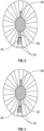
FIG. 2 is a schematic illustration of an embodiment of an inlet arrangement for a gas turbine engine; and -
FIG. 3 is a schematic illustration of another embodiment of an inlet arrangement for a gas turbine engine. - A detailed description of one or more embodiments of the disclosed apparatus and method are presented herein by way of exemplification and not limitation with reference to the Figures.
-
FIG. 1 schematically illustrates agas turbine engine 10. Thegas turbine engine 10 as disclosed herein generally incorporates afan section 12 located at an engine central longitudinal axis A. Thefan section 12 includesfan 22 having a plurality offan blades 14 extending radially outwardly from afan hub 16, and may be disposed in afan case 18. Thefan section 12 drives air along a bypass flow path B in a bypass duct. In some embodiments, thefan section 12 includes a plurality of fan exit guide vanes 20 to turn the airflow exiting thefan 22 along the bypass duct. - The
gas turbine engine 10 includes a twospool gas generator 24, which is radially offset from the engine central longitudinal axis A. Thegas generator 24 has aninlet duct 26 located between circumferentially adjacent fan exit guide vanes 20 which guides a core airflow into thegas generator 24. Thegas generator 24 is a two spool configuration having acompressor section 28, acombustor section 30 and aturbine section 32. Thecompressor section 28 drives air along the core flow path C for compression and communication into thecombustor section 30 then expansion through theturbine section 32. Although depicted as a two-spool configuration in the disclosed non-limiting embodiment, it should be understood that the concepts described herein are not limited to use with two-spool configurations as the teachings may be applied to other types of turbine engines including three-spool architectures. - The
exemplary gas generator 24 generally includes alow speed spool 34 and ahigh speed spool 36. Thelow speed spool 34 generally includes aninner shaft 38 that interconnects alow pressure compressor 40 and alow pressure turbine 42. Thehigh speed spool 36 includes anouter shaft 44 that interconnects ahigh pressure compressor 46 andhigh pressure turbine 48. Acombustor 50 is arranged in thegas generator 24 between thehigh pressure compressor 46 and thehigh pressure turbine 48. Theinner shaft 38 and theouter shaft 44 are concentric and rotate via bearing systems about agas generator axis 54 which is collinear with their longitudinal axes. The core airflow is compressed by thelow pressure compressor 40 then thehigh pressure compressor 46, mixed and burned with fuel in thecombustor 50, then expanded over thehigh pressure turbine 48 andlow pressure turbine 42. Theturbines low speed spool 34 andhigh speed spool 36 in response to the expansion. - The
low pressure turbine 42 of thegas generator 24 is connected to atransition duct 56 such that exhaust from thegas generator 24 flows through thetransition duct 56 to an inlet of afan drive turbine 58 located on the engine central longitudinal axis A. The gas generator exhaust then drives rotation of thefan drive turbine 58. Thefan drive turbine 58 is connected to thefan 22 via a fandrive turbine shaft 60 which extends along the engine central longitudinal axis A. Anauxiliary power core 62 is located between thefan 22 and thefan drive turbine 58 and includes animpeller 64 driven by the fandrive turbine shaft 60. In some embodiments, the fandrive turbine shaft 60 is connected to thefan 22 through a speed change mechanism, which in exemplarygas turbine engine 20 is illustrated as a gearedarchitecture 66 to drive thefan 22 at a different speed than theimpeller 64 and thefan drive turbine 58. The gearedarchitecture 66 may be an epicycle gear train, such as a planetary gear system or other gear system, with a gear reduction ratio of greater than about 2.3:1. It should be understood, however, that the above parameters are only exemplary of one embodiment of a gearedarchitecture 66. - The
auxiliary power core 62 includes twoauxiliary core inlets 68 to admit airflow into theauxiliary power core 62. Theauxiliary core inlets 68 are each located between two circumferentially adjacent fanexit guide vanes 20. Referring now toFIG. 2 , in some embodiments theauxiliary core inlets 68 are located 180 degrees apart relative to the engine central longitudinal axis A. Further, as shown inFIG. 2 , in some embodiments theinlet duct 26 is located radially outboard of one of theauxiliary core inlets 68, while in other embodiments such as shown inFIG. 3 theinlet duct 26 is located radially inboard of one of theauxiliary core inlets 68. - Referring again to
FIG. 1 , theauxiliary power core 62 includes anannular inlet passage 70 extending from theauxiliary core inlets 68 to theimpeller 64. Theimpeller 64 compresses theairflow 82, which is directed to anauxiliary combustor 72, where fuel is injected and mixed with the airflow and combusted. In some embodiments, theauxiliary combustor 72 is a can-annular combustor. Avent passage 74 is located upstream of theauxiliary combustor 72. Theimpeller 64 is configured to direct erosion causing particulates in theairflow 82B, such as sand and dust, radially outwardly and into thevent passage 74 so that such particulates enter the bypass flowpath B, thus preventing erosion of components of thefan drive turbine 58. - A
bleed passage 76 extends from an exit of thelow pressure compressor 40 to theauxiliary power core 62 between theimpeller 64 and theauxiliary combustor 72.Bleed airflow 78A is selectably directed through thebleed passage 76 from thelow pressure compressor 40 to anannular mixing chamber 80 at which thebleed airflow 78A mixes with theauxiliary airflow 82A upstream of theauxiliary combustor 72. - In some embodiments, the
exhaust airflow 84 from theauxiliary combustor 72 is directed into an annularcombustor exhaust manifold 86 and then to an annularturbine inlet manifold 88 upstream of thefan drive turbine 58. A plurality ofoutput passages 90 connect thecombustor exhaust manifold 86 and theturbine inlet manifold 88 to convey theexhaust airflow 84 to thefan drive turbine 58. - Some embodiments, such as shown in
FIG. 1 , include fouroutput passages 90 equally circumferentially spaced about the engine central longitudinal axis A. One skilled in the art will readily appreciate that other quantities ofoutput passages 90 may be utilized, and that the circumferential spacing of theoutput passages 90 may be varied. Further, as illustrated inFIG. 1 , theoutput passages 90 may be skewed circumferentially between thecombustor exhaust manifold 86 and theturbine inlet manifold 88. - The
gas turbine engine 10 is configured to operate in several operational modes. In a first mode theauxiliary power core 62 is operating and thebleed passage 76 is opened to direct thebleed airflow 78A to theauxiliary power core 62. Thebleed airflow 78A and the airflow directed through theauxiliary power core 62 are combusted at theauxiliary combustor 72. This mode is utilized for increased thrust over other operational modes, and may be utilized at, for example, takeoff. In a second mode, thebleed passage 76 is opened to directbleed airflow 78 into theauxiliary power core 62, but theauxiliary combustor 72 is not operated. This second mode has reduced thrust compared to the first mode, but opening thebleed passage 76 decontaminates thehigh speed spool 36 of thegas generator 24 by directing thebleed airflow 78B, containing sand, dust or other contaminants away from thehigh speed spool 36 and to theauxiliary power core 62. Thisbleed airflow 78B is then removed from theauxiliary power core 62 via thevent passage 74. Further, in this second mode of operation theauxiliary power core 62 protects thegas generator 24 from starting vortex and ground vortex conditions. The second mode may be suitable for use for derated takeoff operation, where it is desired to achieve sand separation but do not need full power, compared to the first mode, and reduces fuel consumption versus the first mode. In a third mode, thebleed passage 76 is closed, so nobleed airflow 78 is directed to theauxiliary power core 62. Such a mode may be utilized at, for example, climb and cruise following aircraft takeoff. - The term "about" is intended to include the degree of error associated with measurement of the particular quantity based upon the equipment available at the time of filing the application. For example, "about" can include a range of ± 8% or 5%, or 2% of a given value.
- The terminology used herein is for the purpose of describing particular embodiments only and is not intended to be limiting of the present disclosure. As used herein, the singular forms "a", "an" and "the" are intended to include the plural forms as well, unless the context clearly indicates otherwise. It will be further understood that the terms "comprises" and/or "comprising," when used in this specification, specify the presence of stated features, integers, steps, operations, elements, and/or components, but do not preclude the presence or addition of one or more other features, integers, steps, operations, element components, and/or groups thereof.
- While the present disclosure has been described with reference to an exemplary embodiment or embodiments, it will be understood by those skilled in the art that various changes may be made and equivalents may be substituted for elements thereof without departing from the scope of the present disclosure. In addition, many modifications may be made to adapt a particular situation or material to the teachings of the present disclosure without departing from the essential scope thereof. Therefore, it is intended that the present disclosure not be limited to the particular embodiment disclosed as the best mode contemplated for carrying out this present disclosure, but that the present disclosure will include all embodiments falling within the scope of the claims.
Claims (15)
- A gas turbine engine (10), comprising:a fan (22) disposed at an engine central longitudinal axis (A);a fan drive turbine (58) disposed at the engine central longitudinal axis (A) and configured to drive rotation of the fan (22);a gas generator (24) non-coaxial with the fan drive turbine (58) and operably connected to the fan drive turbine (58) such that exhaust from the gas generator (24) drives rotation of the fan drive turbine (58);an auxiliary power core (62) disposed at the engine central longitudinal axis (A); andone or more bleed passages (76) to connect the gas generator (24) and the auxiliary power core (62);wherein the one or more bleed passages (76) are configured to selectably combine a bleed airflow (78) from the gas generator (24) and an auxiliary core airflow (82) at the auxiliary power core (62) to direct the combined airflow (78A, 82A) to the fan drive turbine (58) to increase output of the fan drive turbine (58).
- The gas turbine engine (10) of claim 1, further comprising a vent passage (74) at the auxiliary power core (62) to selectably direct a portion of the bleed airflow (78B) out of the auxiliary power core (62), wherein, optionally, the bleed airflow (78) is configured to preferably direct entrained sand through the one or more bleed passages (76) and not to continue through gas generator (24).
- The gas turbine engine (10) of claim 1 or 2, further comprising an auxiliary combustor (72) at the auxiliary power core (62) to selectably combust the combined airflow (78A, 82A).
- The gas turbine engine (10) of claim 3, wherein the bleed airflow (78) enters the auxiliary power core (62) at an annular mixing chamber (80) upstream of the auxiliary combustor (72).
- The gas turbine engine (10) of claim 3 or 4, further comprising a plurality of output passages (90) to direct airflow (84) output from the auxiliary combustor (72) to the fan drive turbine (58), wherein the exhaust from the gas generator (24) and the airflow (84) output from the auxiliary combustor (72) are optionally combined at a turbine inlet manifold (88).
- The gas turbine engine (10) of any preceding claim, wherein the fan drive turbine (58) is operably connected to the fan (22) through a speed change mechanism (66).
- The gas turbine engine (10) of any preceding claim, wherein an inlet (68) of the gas generator (24) is located between two circumferentially adjacent fan exit guide vanes (20) located downstream of the fan (22).
- A method of operating a gas turbine engine (10), comprising:driving a fan (22) disposed at an engine central longitudinal axis (A) via operation of a fan drive turbine (58) disposed at the engine central longitudinal axis (A);driving the fan drive turbine (58) via operation of a gas generator (24) disposed non-coaxial with the fan drive turbine (58) such that exhaust from the gas generator (24) drives rotation of the fan drive turbine (58);selectably directing a bleed airflow (78) from the gas generator (24) to an auxiliary power core (62) disposed at the engine central longitudinal axis (A); andcombining the bleed airflow (78) from the gas generator (24) and an auxiliary core airflow (82) at the auxiliary power core (62) to direct the combined airflow (78A, 82A) to the fan drive turbine (58) to increase output of the fan drive turbine (58).
- The method of claim 8, further comprising selectably directing a portion of the bleed airflow (78B) out of the auxiliary power core (62) via a vent passage (74).
- The method of claim 8 or 9, further comprising selectably combusting the combined airflow (78A, 82A) at an auxiliary combustor (72) of the auxiliary power core (62).
- The method of claim 10, further comprising directing airflow (84) output from the auxiliary combustor (72) to the fan drive turbine (58) via a plurality of output passages (90), and optionally further comprising combining the exhaust from the gas generator (24) and the airflow (84) output from the auxiliary combustor (72) at a turbine inlet manifold (88).
- The method of any of claims 8 to 11 or gas turbine engine (10) of any of claims 1 to 7 wherein the gas generator (24) is a two spool gas generator (24) including:a compressor section (28);a combustor (50); anda turbine section (32) all arrayed along a gas generator central axis (54).
- The method or gas turbine engine (10) of claim 12, wherein the one or more bleed passages (76) extend from the gas generator (24) between a low pressure compressor (40) and a high pressure compressor (46) of the compressor section (28).
- The gas turbine engine (10) of claim 13, further comprising an impeller (64) at the auxiliary power core (62) driven by the fan drive turbine (58).
- The method of any of claims 8 to 13, wherein the bleed flow (78) is directed from the gas generator (24) to the auxiliary power core (62) to direct entrained sand through bleed passage (76) and not to continue through gas generator (24).
Applications Claiming Priority (1)
| Application Number | Priority Date | Filing Date | Title |
|---|---|---|---|
| US17/393,508 US11840958B2 (en) | 2021-08-04 | 2021-08-04 | Turbofan with offset gas generator and auxiliary power core |
Publications (2)
| Publication Number | Publication Date |
|---|---|
| EP4137687A1 true EP4137687A1 (en) | 2023-02-22 |
| EP4137687B1 EP4137687B1 (en) | 2024-05-15 |
Family
ID=82786598
Family Applications (1)
| Application Number | Title | Priority Date | Filing Date |
|---|---|---|---|
| EP22188353.1A Active EP4137687B1 (en) | 2021-08-04 | 2022-08-02 | Turbofan with offset gas generator and auxiliary power core |
Country Status (2)
| Country | Link |
|---|---|
| US (1) | US11840958B2 (en) |
| EP (1) | EP4137687B1 (en) |
Families Citing this family (1)
| Publication number | Priority date | Publication date | Assignee | Title |
|---|---|---|---|---|
| FR3101856B1 (en) * | 2019-10-15 | 2024-07-05 | Inst Superieur De L Aeronautique Et De L Espace | Distributed propulsion with remote propulsion modules |
Citations (3)
| Publication number | Priority date | Publication date | Assignee | Title |
|---|---|---|---|---|
| US20020190159A1 (en) * | 2001-06-14 | 2002-12-19 | Snecma Moteurs | Variable cycle propulsion system with compressed air tapping for a supersonic airplane |
| US20060185346A1 (en) * | 2003-04-10 | 2006-08-24 | Rolt Andrew M | Turbofan arrangement |
| EP2915988A1 (en) * | 2014-03-03 | 2015-09-09 | United Technologies Corporation | Offset core engine architecture |
Family Cites Families (10)
| Publication number | Priority date | Publication date | Assignee | Title |
|---|---|---|---|---|
| US3149461A (en) * | 1960-11-18 | 1964-09-22 | Snecma | Composite reaction engine for aircraft with wide ranges of speed |
| US20120272656A1 (en) * | 2011-04-29 | 2012-11-01 | United Technologies Corporation | Multiple core variable cycle gas turbine engine and method of operation |
| DE102013213518A1 (en) | 2013-07-10 | 2015-01-15 | Rolls-Royce Deutschland Ltd & Co Kg | Turbofan engine |
| US10094281B2 (en) | 2014-01-30 | 2018-10-09 | United Technologies Corporation | Gas turbine engine with twin offset gas generators |
| US10415466B2 (en) | 2014-10-27 | 2019-09-17 | United Technologies Corporation | Offset cores for gas turbine engines |
| US10287992B2 (en) * | 2015-08-26 | 2019-05-14 | General Electric Company | Gas turbine engine hybrid variable bleed valve |
| FR3043723B1 (en) | 2015-11-13 | 2017-11-24 | Snecma | PROPELLER ASSEMBLY OF AN AIRCRAFT COMPRISING A GAS GENERATOR, TWO DEPTH BLOWERS AND AN AIR INLET HANDLE |
| US10641124B2 (en) | 2018-06-05 | 2020-05-05 | United Technologies Corporation | Hybrid electric turbine engine |
| GB201915015D0 (en) * | 2019-10-17 | 2019-12-04 | Rolls Royce Plc | Gas turbine engine |
| US11519289B2 (en) | 2019-12-06 | 2022-12-06 | Raytheon Technologies Corporation | Systems and methods for hybrid electric turbine engines |
-
2021
- 2021-08-04 US US17/393,508 patent/US11840958B2/en active Active
-
2022
- 2022-08-02 EP EP22188353.1A patent/EP4137687B1/en active Active
Patent Citations (3)
| Publication number | Priority date | Publication date | Assignee | Title |
|---|---|---|---|---|
| US20020190159A1 (en) * | 2001-06-14 | 2002-12-19 | Snecma Moteurs | Variable cycle propulsion system with compressed air tapping for a supersonic airplane |
| US20060185346A1 (en) * | 2003-04-10 | 2006-08-24 | Rolt Andrew M | Turbofan arrangement |
| EP2915988A1 (en) * | 2014-03-03 | 2015-09-09 | United Technologies Corporation | Offset core engine architecture |
Also Published As
| Publication number | Publication date |
|---|---|
| US11840958B2 (en) | 2023-12-12 |
| US20230037652A1 (en) | 2023-02-09 |
| EP4137687B1 (en) | 2024-05-15 |
Similar Documents
| Publication | Publication Date | Title |
|---|---|---|
| US12055093B2 (en) | Geared turbofan engine with a high ratio of thrust to turbine volume | |
| US10830130B2 (en) | Geared turbofan with three turbines all counter-rotating | |
| US11970984B2 (en) | Gas turbine engine with power density range | |
| JP5514354B2 (en) | Turbine engine with flow control fan and method of operation | |
| US8695324B2 (en) | Multistage tip fan | |
| US4183210A (en) | Gas turbine engine powerplants | |
| US20110120083A1 (en) | Gas turbine engine with outer fans | |
| US7353647B2 (en) | Methods and apparatus for assembling gas turbine engines | |
| US20250043730A1 (en) | Gas turbine engine with electrically driven compressor | |
| EP4137687B1 (en) | Turbofan with offset gas generator and auxiliary power core | |
| US11268444B2 (en) | Turbine cooling arrangement | |
| US12123310B2 (en) | Gas turbine engine with idle thrust ratio | |
| US11781479B2 (en) | Turbofan gas turbine engine with combusted compressor bleed flow | |
| EP4438867A1 (en) | Aircraft engine having two radially offset turbines | |
| US10473028B2 (en) | Clutched compressor section for gas turbine engine |
Legal Events
| Date | Code | Title | Description |
|---|---|---|---|
| PUAI | Public reference made under article 153(3) epc to a published international application that has entered the european phase |
Free format text: ORIGINAL CODE: 0009012 |
|
| STAA | Information on the status of an ep patent application or granted ep patent |
Free format text: STATUS: THE APPLICATION HAS BEEN PUBLISHED |
|
| AK | Designated contracting states |
Kind code of ref document: A1 Designated state(s): AL AT BE BG CH CY CZ DE DK EE ES FI FR GB GR HR HU IE IS IT LI LT LU LV MC MK MT NL NO PL PT RO RS SE SI SK SM TR |
|
| STAA | Information on the status of an ep patent application or granted ep patent |
Free format text: STATUS: REQUEST FOR EXAMINATION WAS MADE |
|
| 17P | Request for examination filed |
Effective date: 20230801 |
|
| RBV | Designated contracting states (corrected) |
Designated state(s): AL AT BE BG CH CY CZ DE DK EE ES FI FR GB GR HR HU IE IS IT LI LT LU LV MC MK MT NL NO PL PT RO RS SE SI SK SM TR |
|
| RAP3 | Party data changed (applicant data changed or rights of an application transferred) |
Owner name: RTX CORPORATION |
|
| GRAP | Despatch of communication of intention to grant a patent |
Free format text: ORIGINAL CODE: EPIDOSNIGR1 |
|
| STAA | Information on the status of an ep patent application or granted ep patent |
Free format text: STATUS: GRANT OF PATENT IS INTENDED |
|
| INTG | Intention to grant announced |
Effective date: 20231208 |
|
| GRAS | Grant fee paid |
Free format text: ORIGINAL CODE: EPIDOSNIGR3 |
|
| GRAA | (expected) grant |
Free format text: ORIGINAL CODE: 0009210 |
|
| STAA | Information on the status of an ep patent application or granted ep patent |
Free format text: STATUS: THE PATENT HAS BEEN GRANTED |
|
| AK | Designated contracting states |
Kind code of ref document: B1 Designated state(s): AL AT BE BG CH CY CZ DE DK EE ES FI FR GB GR HR HU IE IS IT LI LT LU LV MC MK MT NL NO PL PT RO RS SE SI SK SM TR |
|
| REG | Reference to a national code |
Ref country code: CH Ref legal event code: EP |
|
| REG | Reference to a national code |
Ref country code: DE Ref legal event code: R096 Ref document number: 602022003465 Country of ref document: DE |
|
| REG | Reference to a national code |
Ref country code: IE Ref legal event code: FG4D |
|
| REG | Reference to a national code |
Ref country code: LT Ref legal event code: MG9D |
|
| REG | Reference to a national code |
Ref country code: NL Ref legal event code: MP Effective date: 20240515 |
|
| PG25 | Lapsed in a contracting state [announced via postgrant information from national office to epo] |
Ref country code: IS Free format text: LAPSE BECAUSE OF FAILURE TO SUBMIT A TRANSLATION OF THE DESCRIPTION OR TO PAY THE FEE WITHIN THE PRESCRIBED TIME-LIMIT Effective date: 20240915 |
|
| PG25 | Lapsed in a contracting state [announced via postgrant information from national office to epo] |
Ref country code: BG Free format text: LAPSE BECAUSE OF FAILURE TO SUBMIT A TRANSLATION OF THE DESCRIPTION OR TO PAY THE FEE WITHIN THE PRESCRIBED TIME-LIMIT Effective date: 20240515 |
|
| PG25 | Lapsed in a contracting state [announced via postgrant information from national office to epo] |
Ref country code: FI Free format text: LAPSE BECAUSE OF FAILURE TO SUBMIT A TRANSLATION OF THE DESCRIPTION OR TO PAY THE FEE WITHIN THE PRESCRIBED TIME-LIMIT Effective date: 20240515 Ref country code: HR Free format text: LAPSE BECAUSE OF FAILURE TO SUBMIT A TRANSLATION OF THE DESCRIPTION OR TO PAY THE FEE WITHIN THE PRESCRIBED TIME-LIMIT Effective date: 20240515 |
|
| PG25 | Lapsed in a contracting state [announced via postgrant information from national office to epo] |
Ref country code: GR Free format text: LAPSE BECAUSE OF FAILURE TO SUBMIT A TRANSLATION OF THE DESCRIPTION OR TO PAY THE FEE WITHIN THE PRESCRIBED TIME-LIMIT Effective date: 20240816 |
|
| PG25 | Lapsed in a contracting state [announced via postgrant information from national office to epo] |
Ref country code: PT Free format text: LAPSE BECAUSE OF FAILURE TO SUBMIT A TRANSLATION OF THE DESCRIPTION OR TO PAY THE FEE WITHIN THE PRESCRIBED TIME-LIMIT Effective date: 20240916 |
|
| REG | Reference to a national code |
Ref country code: AT Ref legal event code: MK05 Ref document number: 1687075 Country of ref document: AT Kind code of ref document: T Effective date: 20240515 |
|
| PG25 | Lapsed in a contracting state [announced via postgrant information from national office to epo] |
Ref country code: NL Free format text: LAPSE BECAUSE OF FAILURE TO SUBMIT A TRANSLATION OF THE DESCRIPTION OR TO PAY THE FEE WITHIN THE PRESCRIBED TIME-LIMIT Effective date: 20240515 |
|
| PG25 | Lapsed in a contracting state [announced via postgrant information from national office to epo] |
Ref country code: ES Free format text: LAPSE BECAUSE OF FAILURE TO SUBMIT A TRANSLATION OF THE DESCRIPTION OR TO PAY THE FEE WITHIN THE PRESCRIBED TIME-LIMIT Effective date: 20240515 |
|
| PG25 | Lapsed in a contracting state [announced via postgrant information from national office to epo] |
Ref country code: AT Free format text: LAPSE BECAUSE OF FAILURE TO SUBMIT A TRANSLATION OF THE DESCRIPTION OR TO PAY THE FEE WITHIN THE PRESCRIBED TIME-LIMIT Effective date: 20240515 |
|
| PG25 | Lapsed in a contracting state [announced via postgrant information from national office to epo] |
Ref country code: PL Free format text: LAPSE BECAUSE OF FAILURE TO SUBMIT A TRANSLATION OF THE DESCRIPTION OR TO PAY THE FEE WITHIN THE PRESCRIBED TIME-LIMIT Effective date: 20240515 |
|
| PG25 | Lapsed in a contracting state [announced via postgrant information from national office to epo] |
Ref country code: LV Free format text: LAPSE BECAUSE OF FAILURE TO SUBMIT A TRANSLATION OF THE DESCRIPTION OR TO PAY THE FEE WITHIN THE PRESCRIBED TIME-LIMIT Effective date: 20240515 |
|
| PG25 | Lapsed in a contracting state [announced via postgrant information from national office to epo] |
Ref country code: PT Free format text: LAPSE BECAUSE OF FAILURE TO SUBMIT A TRANSLATION OF THE DESCRIPTION OR TO PAY THE FEE WITHIN THE PRESCRIBED TIME-LIMIT Effective date: 20240916 Ref country code: PL Free format text: LAPSE BECAUSE OF FAILURE TO SUBMIT A TRANSLATION OF THE DESCRIPTION OR TO PAY THE FEE WITHIN THE PRESCRIBED TIME-LIMIT Effective date: 20240515 Ref country code: NO Free format text: LAPSE BECAUSE OF FAILURE TO SUBMIT A TRANSLATION OF THE DESCRIPTION OR TO PAY THE FEE WITHIN THE PRESCRIBED TIME-LIMIT Effective date: 20240815 Ref country code: NL Free format text: LAPSE BECAUSE OF FAILURE TO SUBMIT A TRANSLATION OF THE DESCRIPTION OR TO PAY THE FEE WITHIN THE PRESCRIBED TIME-LIMIT Effective date: 20240515 Ref country code: LV Free format text: LAPSE BECAUSE OF FAILURE TO SUBMIT A TRANSLATION OF THE DESCRIPTION OR TO PAY THE FEE WITHIN THE PRESCRIBED TIME-LIMIT Effective date: 20240515 Ref country code: IS Free format text: LAPSE BECAUSE OF FAILURE TO SUBMIT A TRANSLATION OF THE DESCRIPTION OR TO PAY THE FEE WITHIN THE PRESCRIBED TIME-LIMIT Effective date: 20240915 Ref country code: HR Free format text: LAPSE BECAUSE OF FAILURE TO SUBMIT A TRANSLATION OF THE DESCRIPTION OR TO PAY THE FEE WITHIN THE PRESCRIBED TIME-LIMIT Effective date: 20240515 Ref country code: GR Free format text: LAPSE BECAUSE OF FAILURE TO SUBMIT A TRANSLATION OF THE DESCRIPTION OR TO PAY THE FEE WITHIN THE PRESCRIBED TIME-LIMIT Effective date: 20240816 Ref country code: FI Free format text: LAPSE BECAUSE OF FAILURE TO SUBMIT A TRANSLATION OF THE DESCRIPTION OR TO PAY THE FEE WITHIN THE PRESCRIBED TIME-LIMIT Effective date: 20240515 Ref country code: ES Free format text: LAPSE BECAUSE OF FAILURE TO SUBMIT A TRANSLATION OF THE DESCRIPTION OR TO PAY THE FEE WITHIN THE PRESCRIBED TIME-LIMIT Effective date: 20240515 Ref country code: BG Free format text: LAPSE BECAUSE OF FAILURE TO SUBMIT A TRANSLATION OF THE DESCRIPTION OR TO PAY THE FEE WITHIN THE PRESCRIBED TIME-LIMIT Effective date: 20240515 Ref country code: AT Free format text: LAPSE BECAUSE OF FAILURE TO SUBMIT A TRANSLATION OF THE DESCRIPTION OR TO PAY THE FEE WITHIN THE PRESCRIBED TIME-LIMIT Effective date: 20240515 Ref country code: RS Free format text: LAPSE BECAUSE OF FAILURE TO SUBMIT A TRANSLATION OF THE DESCRIPTION OR TO PAY THE FEE WITHIN THE PRESCRIBED TIME-LIMIT Effective date: 20240815 |
|
| PG25 | Lapsed in a contracting state [announced via postgrant information from national office to epo] |
Ref country code: DK Free format text: LAPSE BECAUSE OF FAILURE TO SUBMIT A TRANSLATION OF THE DESCRIPTION OR TO PAY THE FEE WITHIN THE PRESCRIBED TIME-LIMIT Effective date: 20240515 |
|
| PG25 | Lapsed in a contracting state [announced via postgrant information from national office to epo] |
Ref country code: EE Free format text: LAPSE BECAUSE OF FAILURE TO SUBMIT A TRANSLATION OF THE DESCRIPTION OR TO PAY THE FEE WITHIN THE PRESCRIBED TIME-LIMIT Effective date: 20240515 |
|
| PG25 | Lapsed in a contracting state [announced via postgrant information from national office to epo] |
Ref country code: CZ Free format text: LAPSE BECAUSE OF FAILURE TO SUBMIT A TRANSLATION OF THE DESCRIPTION OR TO PAY THE FEE WITHIN THE PRESCRIBED TIME-LIMIT Effective date: 20240515 |
|
| PG25 | Lapsed in a contracting state [announced via postgrant information from national office to epo] |
Ref country code: SK Free format text: LAPSE BECAUSE OF FAILURE TO SUBMIT A TRANSLATION OF THE DESCRIPTION OR TO PAY THE FEE WITHIN THE PRESCRIBED TIME-LIMIT Effective date: 20240515 Ref country code: RO Free format text: LAPSE BECAUSE OF FAILURE TO SUBMIT A TRANSLATION OF THE DESCRIPTION OR TO PAY THE FEE WITHIN THE PRESCRIBED TIME-LIMIT Effective date: 20240515 |
|
| PG25 | Lapsed in a contracting state [announced via postgrant information from national office to epo] |
Ref country code: SM Free format text: LAPSE BECAUSE OF FAILURE TO SUBMIT A TRANSLATION OF THE DESCRIPTION OR TO PAY THE FEE WITHIN THE PRESCRIBED TIME-LIMIT Effective date: 20240515 |
|
| PG25 | Lapsed in a contracting state [announced via postgrant information from national office to epo] |
Ref country code: SM Free format text: LAPSE BECAUSE OF FAILURE TO SUBMIT A TRANSLATION OF THE DESCRIPTION OR TO PAY THE FEE WITHIN THE PRESCRIBED TIME-LIMIT Effective date: 20240515 Ref country code: SK Free format text: LAPSE BECAUSE OF FAILURE TO SUBMIT A TRANSLATION OF THE DESCRIPTION OR TO PAY THE FEE WITHIN THE PRESCRIBED TIME-LIMIT Effective date: 20240515 Ref country code: RO Free format text: LAPSE BECAUSE OF FAILURE TO SUBMIT A TRANSLATION OF THE DESCRIPTION OR TO PAY THE FEE WITHIN THE PRESCRIBED TIME-LIMIT Effective date: 20240515 Ref country code: EE Free format text: LAPSE BECAUSE OF FAILURE TO SUBMIT A TRANSLATION OF THE DESCRIPTION OR TO PAY THE FEE WITHIN THE PRESCRIBED TIME-LIMIT Effective date: 20240515 Ref country code: DK Free format text: LAPSE BECAUSE OF FAILURE TO SUBMIT A TRANSLATION OF THE DESCRIPTION OR TO PAY THE FEE WITHIN THE PRESCRIBED TIME-LIMIT Effective date: 20240515 Ref country code: CZ Free format text: LAPSE BECAUSE OF FAILURE TO SUBMIT A TRANSLATION OF THE DESCRIPTION OR TO PAY THE FEE WITHIN THE PRESCRIBED TIME-LIMIT Effective date: 20240515 |
|
| PG25 | Lapsed in a contracting state [announced via postgrant information from national office to epo] |
Ref country code: IT Free format text: LAPSE BECAUSE OF FAILURE TO SUBMIT A TRANSLATION OF THE DESCRIPTION OR TO PAY THE FEE WITHIN THE PRESCRIBED TIME-LIMIT Effective date: 20240515 |
|
| REG | Reference to a national code |
Ref country code: DE Ref legal event code: R097 Ref document number: 602022003465 Country of ref document: DE |
|
| PLBE | No opposition filed within time limit |
Free format text: ORIGINAL CODE: 0009261 |
|
| STAA | Information on the status of an ep patent application or granted ep patent |
Free format text: STATUS: NO OPPOSITION FILED WITHIN TIME LIMIT |
|
| PG25 | Lapsed in a contracting state [announced via postgrant information from national office to epo] |
Ref country code: LU Free format text: LAPSE BECAUSE OF NON-PAYMENT OF DUE FEES Effective date: 20240802 |
|
| 26N | No opposition filed |
Effective date: 20250218 |
|
| PG25 | Lapsed in a contracting state [announced via postgrant information from national office to epo] |
Ref country code: SI Free format text: LAPSE BECAUSE OF FAILURE TO SUBMIT A TRANSLATION OF THE DESCRIPTION OR TO PAY THE FEE WITHIN THE PRESCRIBED TIME-LIMIT Effective date: 20240515 Ref country code: MC Free format text: LAPSE BECAUSE OF FAILURE TO SUBMIT A TRANSLATION OF THE DESCRIPTION OR TO PAY THE FEE WITHIN THE PRESCRIBED TIME-LIMIT Effective date: 20240515 |
|
| REG | Reference to a national code |
Ref country code: BE Ref legal event code: MM Effective date: 20240831 |
|
| PG25 | Lapsed in a contracting state [announced via postgrant information from national office to epo] |
Ref country code: BE Free format text: LAPSE BECAUSE OF NON-PAYMENT OF DUE FEES Effective date: 20240831 |
|
| PG25 | Lapsed in a contracting state [announced via postgrant information from national office to epo] |
Ref country code: IE Free format text: LAPSE BECAUSE OF NON-PAYMENT OF DUE FEES Effective date: 20240802 |
|
| PG25 | Lapsed in a contracting state [announced via postgrant information from national office to epo] |
Ref country code: SE Free format text: LAPSE BECAUSE OF FAILURE TO SUBMIT A TRANSLATION OF THE DESCRIPTION OR TO PAY THE FEE WITHIN THE PRESCRIBED TIME-LIMIT Effective date: 20240515 |
|
| PGFP | Annual fee paid to national office [announced via postgrant information from national office to epo] |
Ref country code: DE Payment date: 20250724 Year of fee payment: 4 |
|
| PGFP | Annual fee paid to national office [announced via postgrant information from national office to epo] |
Ref country code: FR Payment date: 20250723 Year of fee payment: 4 |
|
| PG25 | Lapsed in a contracting state [announced via postgrant information from national office to epo] |
Ref country code: CY Free format text: LAPSE BECAUSE OF FAILURE TO SUBMIT A TRANSLATION OF THE DESCRIPTION OR TO PAY THE FEE WITHIN THE PRESCRIBED TIME-LIMIT; INVALID AB INITIO Effective date: 20220802 |
|
| PG25 | Lapsed in a contracting state [announced via postgrant information from national office to epo] |
Ref country code: HU Free format text: LAPSE BECAUSE OF FAILURE TO SUBMIT A TRANSLATION OF THE DESCRIPTION OR TO PAY THE FEE WITHIN THE PRESCRIBED TIME-LIMIT; INVALID AB INITIO Effective date: 20220802 |
|
| REG | Reference to a national code |
Ref country code: CH Ref legal event code: H13 Free format text: ST27 STATUS EVENT CODE: U-0-0-H10-H13 (AS PROVIDED BY THE NATIONAL OFFICE) Effective date: 20260324 |
|
| PG25 | Lapsed in a contracting state [announced via postgrant information from national office to epo] |
Ref country code: CH Free format text: LAPSE BECAUSE OF NON-PAYMENT OF DUE FEES Effective date: 20250831 |