EP4137678B1 - Systems and methods for internal spline lubrication - Google Patents
Systems and methods for internal spline lubrication Download PDFInfo
- Publication number
- EP4137678B1 EP4137678B1 EP22190432.9A EP22190432A EP4137678B1 EP 4137678 B1 EP4137678 B1 EP 4137678B1 EP 22190432 A EP22190432 A EP 22190432A EP 4137678 B1 EP4137678 B1 EP 4137678B1
- Authority
- EP
- European Patent Office
- Prior art keywords
- shaft
- oil
- drain outlet
- aperture
- tube
- Prior art date
- Legal status (The legal status is an assumption and is not a legal conclusion. Google has not performed a legal analysis and makes no representation as to the accuracy of the status listed.)
- Active
Links
Images


Classifications
-
- F—MECHANICAL ENGINEERING; LIGHTING; HEATING; WEAPONS; BLASTING
- F01—MACHINES OR ENGINES IN GENERAL; ENGINE PLANTS IN GENERAL; STEAM ENGINES
- F01D—NON-POSITIVE DISPLACEMENT MACHINES OR ENGINES, e.g. STEAM TURBINES
- F01D25/00—Component parts, details, or accessories, not provided for in, or of interest apart from, other groups
- F01D25/18—Lubricating arrangements
-
- F—MECHANICAL ENGINEERING; LIGHTING; HEATING; WEAPONS; BLASTING
- F02—COMBUSTION ENGINES; HOT-GAS OR COMBUSTION-PRODUCT ENGINE PLANTS
- F02C—GAS-TURBINE PLANTS; AIR INTAKES FOR JET-PROPULSION PLANTS; CONTROLLING FUEL SUPPLY IN AIR-BREATHING JET-PROPULSION PLANTS
- F02C7/00—Features, components parts, details or accessories, not provided for in, or of interest apart form groups F02C1/00 - F02C6/00; Air intakes for jet-propulsion plants
- F02C7/06—Arrangements of bearings; Lubricating
-
- F—MECHANICAL ENGINEERING; LIGHTING; HEATING; WEAPONS; BLASTING
- F01—MACHINES OR ENGINES IN GENERAL; ENGINE PLANTS IN GENERAL; STEAM ENGINES
- F01D—NON-POSITIVE DISPLACEMENT MACHINES OR ENGINES, e.g. STEAM TURBINES
- F01D15/00—Adaptations of machines or engines for special use; Combinations of engines with devices driven thereby
- F01D15/12—Combinations with mechanical gearing
-
- F—MECHANICAL ENGINEERING; LIGHTING; HEATING; WEAPONS; BLASTING
- F01—MACHINES OR ENGINES IN GENERAL; ENGINE PLANTS IN GENERAL; STEAM ENGINES
- F01D—NON-POSITIVE DISPLACEMENT MACHINES OR ENGINES, e.g. STEAM TURBINES
- F01D21/00—Shutting-down of machines or engines, e.g. in emergency; Regulating, controlling, or safety means not otherwise provided for
- F01D21/003—Arrangements for testing or measuring
-
- F—MECHANICAL ENGINEERING; LIGHTING; HEATING; WEAPONS; BLASTING
- F01—MACHINES OR ENGINES IN GENERAL; ENGINE PLANTS IN GENERAL; STEAM ENGINES
- F01D—NON-POSITIVE DISPLACEMENT MACHINES OR ENGINES, e.g. STEAM TURBINES
- F01D25/00—Component parts, details, or accessories, not provided for in, or of interest apart from, other groups
- F01D25/16—Arrangement of bearings; Supporting or mounting bearings in casings
- F01D25/162—Bearing supports
-
- F—MECHANICAL ENGINEERING; LIGHTING; HEATING; WEAPONS; BLASTING
- F01—MACHINES OR ENGINES IN GENERAL; ENGINE PLANTS IN GENERAL; STEAM ENGINES
- F01D—NON-POSITIVE DISPLACEMENT MACHINES OR ENGINES, e.g. STEAM TURBINES
- F01D25/00—Component parts, details, or accessories, not provided for in, or of interest apart from, other groups
- F01D25/18—Lubricating arrangements
- F01D25/20—Lubricating arrangements using lubrication pumps
-
- F—MECHANICAL ENGINEERING; LIGHTING; HEATING; WEAPONS; BLASTING
- F01—MACHINES OR ENGINES IN GENERAL; ENGINE PLANTS IN GENERAL; STEAM ENGINES
- F01D—NON-POSITIVE DISPLACEMENT MACHINES OR ENGINES, e.g. STEAM TURBINES
- F01D5/00—Blades; Blade-carrying members; Heating, heat-insulating, cooling or antivibration means on the blades or the members
- F01D5/02—Blade-carrying members, e.g. rotors
- F01D5/026—Shaft to shaft connections
-
- F—MECHANICAL ENGINEERING; LIGHTING; HEATING; WEAPONS; BLASTING
- F05—INDEXING SCHEMES RELATING TO ENGINES OR PUMPS IN VARIOUS SUBCLASSES OF CLASSES F01-F04
- F05D—INDEXING SCHEME FOR ASPECTS RELATING TO NON-POSITIVE-DISPLACEMENT MACHINES OR ENGINES, GAS-TURBINES OR JET-PROPULSION PLANTS
- F05D2220/00—Application
- F05D2220/30—Application in turbines
- F05D2220/32—Application in turbines in gas turbines
- F05D2220/323—Application in turbines in gas turbines for aircraft propulsion, e.g. jet engines
-
- F—MECHANICAL ENGINEERING; LIGHTING; HEATING; WEAPONS; BLASTING
- F05—INDEXING SCHEMES RELATING TO ENGINES OR PUMPS IN VARIOUS SUBCLASSES OF CLASSES F01-F04
- F05D—INDEXING SCHEME FOR ASPECTS RELATING TO NON-POSITIVE-DISPLACEMENT MACHINES OR ENGINES, GAS-TURBINES OR JET-PROPULSION PLANTS
- F05D2240/00—Components
- F05D2240/50—Bearings
- F05D2240/54—Radial bearings
-
- F—MECHANICAL ENGINEERING; LIGHTING; HEATING; WEAPONS; BLASTING
- F05—INDEXING SCHEMES RELATING TO ENGINES OR PUMPS IN VARIOUS SUBCLASSES OF CLASSES F01-F04
- F05D—INDEXING SCHEME FOR ASPECTS RELATING TO NON-POSITIVE-DISPLACEMENT MACHINES OR ENGINES, GAS-TURBINES OR JET-PROPULSION PLANTS
- F05D2240/00—Components
- F05D2240/60—Shafts
- F05D2240/61—Hollow
-
- F—MECHANICAL ENGINEERING; LIGHTING; HEATING; WEAPONS; BLASTING
- F05—INDEXING SCHEMES RELATING TO ENGINES OR PUMPS IN VARIOUS SUBCLASSES OF CLASSES F01-F04
- F05D—INDEXING SCHEME FOR ASPECTS RELATING TO NON-POSITIVE-DISPLACEMENT MACHINES OR ENGINES, GAS-TURBINES OR JET-PROPULSION PLANTS
- F05D2240/00—Components
- F05D2240/60—Shafts
- F05D2240/63—Glands for admission or removal of fluids from shafts
-
- F—MECHANICAL ENGINEERING; LIGHTING; HEATING; WEAPONS; BLASTING
- F05—INDEXING SCHEMES RELATING TO ENGINES OR PUMPS IN VARIOUS SUBCLASSES OF CLASSES F01-F04
- F05D—INDEXING SCHEME FOR ASPECTS RELATING TO NON-POSITIVE-DISPLACEMENT MACHINES OR ENGINES, GAS-TURBINES OR JET-PROPULSION PLANTS
- F05D2260/00—Function
- F05D2260/60—Fluid transfer
- F05D2260/602—Drainage
-
- F—MECHANICAL ENGINEERING; LIGHTING; HEATING; WEAPONS; BLASTING
- F05—INDEXING SCHEMES RELATING TO ENGINES OR PUMPS IN VARIOUS SUBCLASSES OF CLASSES F01-F04
- F05D—INDEXING SCHEME FOR ASPECTS RELATING TO NON-POSITIVE-DISPLACEMENT MACHINES OR ENGINES, GAS-TURBINES OR JET-PROPULSION PLANTS
- F05D2260/00—Function
- F05D2260/98—Lubrication
Definitions
- the invention relates generally to gas turbine engines and, more particularly, to lubrication systems used in such engines.
- a gas turbine engine has a lubrication system for circulating lubricant (e.g. oil) through a plurality of components, such as bearings, spline couplings, and so on.
- lubricant e.g. oil
- nozzles are used to jet the lubricant toward the components.
- US 2016/032769 discloses an aircraft engine with a lubrication passage system which receives oil under pressure to lubricate and cool the bearing of said engine. The system receives oil from a nozzle into a bore of the outer shaft through a multiple of apertures in a radial step and oil enters essentially axially into the shaft. An axial oil scoop that extends from the radial step facilities oil flow into the apertures.
- US 3 621 937 discloses a lubrication system including a hollow first shaft which is splined to a second rotary shaft, a lubricating conduit mounted within and spaced from first shaft, means for supplying the interior of said conduit with lubricant, a closure member extending across the interior of the first shaft to close the end of said conduit, an annular reservoir located between said conduit and first shaft, the conduit and the closure member having apertures therein for the passage of lubricant to the reservoir.
- WO 2014/137571 discloses an input coupling for a fan drive gear system including features for maintaining lubricant within a splined interface.
- the fan drive gear system includes a gear rotatable about an axis that includes an inner spline.
- the input coupling includes an outer spline engaged to the inner spline of the gear.
- the input coupling includes an aft oil dam for maintaining lubricant within an interface between the outer spline and the inner spline.
- an aircraft engine comprising: a shaft rotatable about a central axis and engaged at an end thereof to a rotatable load via splines; a reference tube circumferentially extending around the shaft, the reference tube having a first end secured to the shaft for rotation with the shaft and a second end free relative to the shaft for measuring a deformation of the shaft, the reference tube defining at least one tube aperture through the reference tube; an oil nozzle fluidly connected to a source of oil, the oil nozzle defining an exit flow axis intersecting the at least one tube aperture for injecting oil through the reference tube, the shaft defining at least one shaft aperture extending through the shaft, an oil flow path extending from the oil nozzle to the splines via the at least one tube aperture and via the at least one shaft aperture for lubricating the splines; and a drain outlet located radially outwardly of an inlet of the at least one shaft aperture for outputting excess oil out of an annular gap defined between the shaft and the
- the aircraft engine described above may include any of the following features, in any combinations.
- the drain outlet is located downstream of the at least one tube aperture relative to an oil flow from the oil nozzle.
- the shaft defines a pool circumferentially extending around the central axis for receiving oil from the oil nozzle, the at least one shaft aperture in fluid flow communication with the pool, the drain outlet axially aligned with the pool and located radially outwardly of the pool.
- the shaft has a main section and an end section, the end section defining the splines, a diameter of the main section less than that of the end section, the pool located proximate an intersection between the main section and the end section.
- the drain outlet is defined through the reference tube.
- the drain outlet extends in a direction having a radial component relative to the central axis.
- the aircraft engine includes a sensor for measuring a rotation of the shaft in relationship to the reference tube, the drain outlet being axially offset from the sensor.
- the drain outlet is an annular space defined radially between an end of the reference tube and the shaft.
- a bearing is in abutment against with the end of the reference tube, the bearing having an inner race secured for rotation with the shaft, the inner race defining oil passages in fluid communication with the annular space.
- a bearing is rollingly engaged to the reference tube and a bearing housing circumferentially extending around the central axis and defining a bearing cavity containing the bearing, the drain outlet communicating with the bearing cavity.
- a method of lubricating a splines of a shaft of an aircraft engine comprising: injecting oil through at least one tube aperture defined through the reference tube; directing the injected oil toward the splines via at least one shaft aperture defined through the shaft; lubricating the splines with the injected oil; and flowing excess oil out of an annular gap between the shaft and the reference tube via a drain outlet located radially outwardly of an inlet of the at least one shaft aperture.
- the method described above may include any of the following features, in any combinations.
- the flowing of the excess oil via the drain outlet includes flowing the excess via the drain outlet located downstream of the at least one tube aperture relative to a flow of the injected oil.
- the directing of the injected oil toward the splines includes flowing the oil in a pool circumferentially extending around a central axis and flowing the oil from the pool through the at least one shaft aperture, the drain outlet being axially aligned with the pool and located radially outwardly of the pool.
- the flowing of the excess oil includes flowing the excess oil through the drain outlet defined through the reference tube.
- the flowing of the excess oil through the drain outlet includes flowing the excess oil through the reference tube in a direction having a radial component relative to the central axis.
- the flowing of the excess oil includes flowing the excess oil through the drain outlet communicating with a bearing cavity.
- flowing of the excess oil includes flowing the excess oil through the drain outlet being an annular space defined radially between an end of the reference tube and the shaft.
- the method includes flowing the excess oil out of the annular gap and in oil passages defined by an inner race of a bearing in abutment against an end of the reference tube.
- the flowing of the excess oil through the drain outlet includes flowing the excess oil in a bearing cavity defined by a bearing housing.
- the method includes flowing the excess oil via a secondary drain outlet located axially aft of the at least one tube aperture.
- Fig. 1 illustrates an aircraft engine depicted as a gas turbine engine 10 of a type preferably provided for use in subsonic flight, generally comprising in serial flow communication a fan 12 through which ambient air is propelled, a compressor section 14 for pressurizing the air, a combustor 16 in which the compressed air is mixed with fuel and ignited for generating an annular stream of hot combustion gases, and a turbine section 18 for extracting energy from the combustion gases.
- the fan 12, the compressor section 14, and the turbine section 18 are rotatable about a central axis 11 of the gas turbine engine 10.
- the gas turbine engine 10 may include a low-pressure shaft 22 and a high pressure shaft 20.
- the low- and high-pressure shafts 22, 20 are concentric and rotatable one relative to the other about the central axis 11.
- the engine 10 may include a lubrication system S for circulating a lubricant, such as oil, toward and from components in need of lubrication.
- a lubricant such as oil
- These components may include, for instance, bearings, spline, and so on.
- the low-pressure shaft 22 may be in driving engagement with a rotatable load L, which may be the fan 12 as illustrated in Fig. 1 , via a torque shaft 24.
- the torque shaft 24 may be a portion of the low-pressure shaft 22.
- the torque shaft 24 and the low-pressure shaft 22 may be monolithic.
- the low-pressure shaft 22 and the torque shaft 24 may alternatively be two distinct components secured to one another.
- the torque shaft 24 may have an end 24a defining splines 24b. In the embodiment shown, the splines 24b are defined on an inner side of the torque shaft 24, which is hollow in the embodiment shown.
- the splines 24b are matingly engaged with correspondingly mating splines on the Low-pressure shaft 22 to allow a rotational input to the transmitted from the low-pressure shaft 22 to the rotatable load L.
- the rotatable load L is depicted as corresponding to the fan 12, the rotatable load may be, alternatively, a propeller, a helicopter rotor, an input of a reduction gearbox, an accessory, and so on.
- splines 24b it may be required to lubricate the splines 24b for proper operation. This may be done by injecting oil toward the splines 24b from within an opposite end of the low-pressure shaft 22. However, in some cases, a length of the low-pressure shaft 22 is such that oil injected from the opposite end of the low-pressure shaft 22 may not reach the splines 24b. It is therefore contemplated herein to inject the oil toward the splines 24b from outside of the low-pressure shaft 22.
- the torque shaft 24 is part of an assembly 100 including a reference tube 28; the reference tube 28 circumferentially extending around the torque shaft 24.
- the reference tube 28 has a fore end 28a proximate to the splines 24b and an aft end 28b at an intersection between the torque shaft 24 and the low-pressure shaft 22.
- the aft end 28b of the reference tube 28 is secured to the torque shaft 24.
- fasteners are used to secure the aft end 28b of the reference tube 28 to the torque shaft 24.
- Other fastening means are contemplated.
- the fore end 28a of the reference tube 28 is rotatable relative to the torque shaft 24 such that the fore end 28a is rotationally free relative to the torque shaft 24.
- the reference tube 28 may not transfer torque from the low-pressure shaft 22 to the rotatable load L.
- the combination of the torque shaft 24 and of the reference tube 28 may be used to measure the torque applied by the engine 10 on the rotatable load L.
- Dimensions of the torque shaft 24 are known and, in function of those dimensions, it may be possible to determine the torque transmitted by the low-pressure shaft 22 to the rotatable load L. This may be achieved by measuring a deformation of the torque shaft 24 as a result of the driving of the rotatable load L. This deformation is in a circumferential direction relative to the central axis 11.
- a first reference point on the torque shaft 24 and axially aligned with the aft end 28b of the reference tube 28 may be circumferentially aligned with a second reference point on the torque shaft 24 and axially aligned with the fore end 28a of the reference tube 28 when the rotatable load L is at rest (non-rotating).
- the first and second reference points may become circumferentially offset from one another.
- a magnitude of this offset increases with an increase of the torque transmitted by the low-pressure shaft 22 to the rotatable load L.
- a sensor 32 which may be a capacitance probe, may be used to measure the magnitude of this offset.
- the sensor 32 may be operatively coupled to a controller that has instructions stored thereon to translate a value of the magnitude of the offset in a torque value.
- the reference tube 28 may be used herein to report the position of the second reference point at a location closer to the sensor 32.
- the reference tube 28 since the fore end 28a of the reference tube 28 is free relative to the torque shaft 24 (i.e., it is not secured to the torque shaft 24; it is free; it is cantilevered; it is unconnected rigidly), the reference tube 28 may not be deformed following the transmission of a rotational input form the low-pressure shaft 22 to the rotatable load L via the torque shaft 24, as it is not used for load transmission - it is only rigidly connected to the shaft 24 or 22 at one end, away from the sensor 32.
- the lubrication system may include a conduit including a line 34 fluidly connected to a source of lubricant 36, such as an oil tank.
- a nozzle 38 is hydraulically connected to the line 34 and is configured to inject oil for lubricating the splines 24b.
- the nozzle 38 and the spline 24b are on respective opposite sides of the torque shaft 24.
- one or more apertures 28c is defined through the reference tube 28 to allow the oil to circulate within an annular gap G located radially between the torque shaft 24 and the reference tube 28 relative to the central axis 11.
- One or more apertures 24c is defined through a wall of the torque shaft 24 to allow oil to circulate from the gap G to an interior I of the torque shaft 24 to reach the splines 24b.
- Both of the apertures 28c, 24c defined through the reference tube 28 and the torque shaft 24 may be located proximate to the fore end 28a of the reference tube 28 and in close proximity to the spline 24b.
- the aperture(s) 24c may extend generally or substantially axially. In an embodiment, the aperture(s) 24c is(are) an axial aperture(s).
- the torque shaft 24 may define a pool, or oil dam, 24d for receiving and accumulating oil jetted by the nozzle 38.
- the pool 24d is annular and extends circumferentially all around the central axis 11.
- the pool 24d is defined on an outer side of the torque shaft 24. More specifically, and in the embodiment shown, the torque shaft 24 has main section 24e and an end section 24f.
- the splines 24b is defined by the end section 24f of the shaft 24.
- a diameter of the main section 24e is less than a diameter of the end section 24f.
- the pool 24d is located proximate to the intersection between the main and end sections 24e, 24f of the torque shaft 24, though it may be elsewhere.
- the change in diameter is abrupt such that the main and end sections 24e, 24f of the torque shaft 24 are connected by an annular wall section 24g of the torque shaft 24, or like step; the annular wall section 24g may extend substantially radially relative to the central axis 11 from the main section 24e to the end section 24g, or may have a radial component to its direction.
- the torque shaft 24 may define an axial protrusion 24h that extends substantially axially along the central axis 11 and away from the splines 24b and from the annular wall section 24g.
- a lip 24i extends from an end of the axial protrusion 24h.
- the lip 24i extends radially inwardly toward the central axis 11.
- the pool 24d is defined by a cooperation of the annular wall section 24g, the axial protrusion 24h, and the lip 24i.
- the wall section 24g, the axial protrusions 24h, and the lip 24i may be annular and may extend circumferentially all around the central axis 11. These components may be monolithic parts of the shaft 24, or add-on components.
- the shaft aperture 24c defined through the torque shaft 24 extends generally axially through the annular wall section 24g of the torque shaft 24.
- the shaft aperture 24c has an inlet end 24j; a tip 24k of the lip 24i being located radially inwardly of the inlet end 24j of the shaft aperture 24c relative to the central axis 11. That is, the tip 24k of the lip 24i may be closer to the central axis 11 than the inlet end 24j of the shaft aperture 24c. This may allow oil to accumulate in the pool 24d by centrifugal effect.
- the shaft aperture 24c has an outlet end 24l that may be radially aligned with the inlet end 24j.
- the outlet end 24l of the shaft aperture 24c is located radially inwardly of the inlet end 24j such that the shaft aperture 24c slopes toward the central axis 11 from the inlet end 24j to the outlet end 24l.
- the slope may assist in directing the oil from the pool 24d to the spline 24b, again by the centrifugal effect.
- the sloping may allow to recuperate a greater amount of oil before the shaft aperture 24c becomes blocked by a rotation of the torque shaft 24 compared to a configuration in which the shaft aperture 24c is parallel to the central axis 11.
- the sloping may allow to scoop more oil compared to a configuration in which the shaft aperture 24c is parallel to the central axis 11.
- An exit flow axis A of the nozzle 38 may intersect the torque shaft 24 at a location that may be axially aligned with the pool 24d relative to the central axis 11.
- the nozzle 38 may be angled relative to the central axis to inject oil in proximity of the pool 24d.
- the oil injected by the nozzle 38 along the exit flow axis A passes through the reference tube 28 via the tube aperture 28c defined therethrough, reaches the pool 24d where it may accumulate, and flows toward the spline 24b through the shaft aperture 24c.
- a flow path extends from the nozzle 38, to the tube aperture 28c through the reference tube 28, to the gap G between the torque shaft 24 and the reference tube 28, to the pool 24d, to the shaft aperture 24c defined through the torque shaft 24 and to the splines 24b.
- the tube aperture 28c defined through the reference tube 28 may have an aperture axis that may have solely a radial component such that the aperture axis is normal to the reference tube 28.
- the aperture axis may further have a circumferential component and/or an axial component relative to the central axis 11. This may allow the tube aperture 28c to have a scooping effect.
- the tube aperture 28c may be machined normal to central axis 11 or at the same angle of incoming oil jet to create a scoop effect.
- More than one nozzle 38 may be used.
- the aperture axis may be parallel to the exit flow axis A of the nozzle 38.
- the shaft aperture 24c may extend solely axially or may extend along a direction having a radial and/or a circumferential component relative to the central axis 11 to assist in scooping the oil from the pool 24d.
- oil injected in the gap G by the nozzle 38 and through the tube aperture 28c may leak out of the gap G via a space between the fore end 28a of the reference tube 28 and the torque shaft 24.
- the oil that leaks in this manner may reach the sensor 32. This may impede proper operation of the sensor 32 and affect its readings. More specifically, a portion of the oil jetted by the nozzle 38 may not reach its target for various reason (e.g., oil brooming, targeting tolerances, and rotation speed of the shafts) and be "trapped" between the two shafts.
- the oil trapped may prevent incoming oil to reach its target efficiently by interference and churning. A portion of the oil can also reached undesired locations such as the sensor 32.
- the oil may become trapped and may affect dynamics of the torque shaft 24. In some cases, the oil may flow against hot surfaces, which may create coaking.
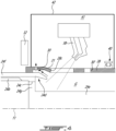
- the reference tube 28 is rollingly supported by a bearing 40 located within a bearing cavity 41 defined by a bearing housing 42.
- the nozzle 38 is located within the bearing cavity 41 such that oil that does not reach the tube aperture 28c may flow in the bearing cavity 41 to be subsequently scavenged and re-used.
- a drain outlet 30 is provided to allow excess oil to exit the annular gap G between the reference tube 28 and the torque shaft 24 and flow in the bearing cavity 41 to be recycled.
- the oil may reach an annular cavity 31 defined radially between the reference tube 28 and the torque shaft 24 and axially overlapping the pool 24d.
- the annular cavity 31 may be part of the annular gap G.
- the drain outlet 30 communicates with the annular cavity 31 and allows the oil to exit the annular cavity 31.
- the drain outlet 30 is defined through the reference tube 28 proximate its fore end 28a.
- the drain outlet 30 is located radially outwardly of the inlet end 24j of the shaft aperture 24c.
- the aperture 30 is located downstream of the tube aperture 28c relative to an oil flow flowing from the oil nozzle 38.
- the drain outlet 30 is axially offset from the sensor 32 such that the excess oil exiting the gap G between the reference tube 28 and the torque shaft 30 may be free of interaction with the sensor 32.
- the sensor 32 is outside of the bearing cavity 41 and the drain outlet 30 is in fluid flow communication with the bearing cavity 41.
- the oil that accumulates in the annular cavity 31 may flow naturally out therefrom via the drain outlet 30 rather than flow out of the annular cavity 31 via an intersection between the reference tube 28 and the torque shaft 24.
- the oil may flow along a path of least resistance.
- Oil may therefore remain in the bearing cavity 41 for subsequent recycling rather than flow out where it may cause issues thanks to the drain outlet 30.
- the annular cavity 31 is defined between a portion of the reference tube 28 that has a greater diameter than a remainder of the reference tube 28.
- the drain outlet 30 may be defined through this portion of the reference tube 28 having the greater diameter.
- the drain outlet 30 is axially aligned with the pool 24d and is located radially outwardly of the pool 24d relative to the central axis 11.
- the drain outlet 30 extends in a direction having a radial component relative to the central axis 11.
- the drain outlet 30 may extend solely radially relative to the central axis 11.
- a secondary drain outlet 30' is provided on an opposite sides of the tube aperture 28c such that the drain and secondary drain outlets 30, 30' are axially respectively fore and aft of the tube aperture 28c.
- the secondary drain outlets 30' may be located upstream of the tube aperture 28c relative to the oil flow flowing towards the splines 24b of the torque shaft 24.
- an inlet of the drain outlet 30 is located radially outwardly of an inlet of the secondary drain outlet 30'.
- the drain outlet 130 is defined as an annular spacing between the fore end 128a of the reference tube 128 and the torque shaft 24, more specifically, between the fore end 128a of the reference tube 128 and the end section 24f of the torque shaft 24.
- a bearing 50 is located within a bearing housing 142 and rollingly supports the torque shaft 24 and has an inner race 51 defining oil passages 52 for lubrication of rollers 53 of the bearing 50.
- the fore end 128a of the reference tube 128 may be in abutment against the inner race 51 of the bearing 50 such that the drain outlet 130 communicates with the oil passages 52 of the inner race 51. This may allow to leverage the excess oil for lubricating the bearing 50.
- the excess oil that does not reach the pool 24d may flow out of the annular gap G via the annular space 130 along the arrows A1 shown in Fig. 5 .
- a secondary drain outlet 30' is provided on an opposite sides of the tube aperture 28c such that the drain and secondary drain outlets 30, 30' are axially respectively fore and aft of the tube aperture 28c.
- the secondary drain outlets 30' may be located upstream of the tube aperture 28c relative to the oil flow flowing towards the splines 24b of the torque shaft 24.
- the disclosed configurations having the drain outlet 30, 130 may minimize the probability of generating oil swirling/interference between the reference tube 28 and the torque shaft 24; may control the accumulation inside the reference tube 28; may prevent oil to reach specific surface/components (e.g. sensor 32, hot surfaces, seals); and may recycle the un-used oil for lubrication of other components such as sleeve, journal, bearing, splines.
- the oil drains can be used on one or both side of the tube apertures 28c.
- a method of lubricating the splines 24b is shown at 600.
- the method includes injecting the oil through the at least one tube aperture 28c defined through the reference tube 28 at 602; directing the injected oil toward the splines 24b via the at least one shaft aperture 24c defined through the torque shaft 24 at 604; lubricating the splines 24b with the injected oil at 606; and flowing the excess oil out of the annular gap G between the torque shaft 24 and the reference tube 28 via the drain outlet 30, 130, 30' located radially outwardly of an inlet of the at least one shaft aperture 24c at 608.
- the flowing of the excess oil via the drain outlet 30 at 608 includes flowing the excess oil via the drain outlet 30, 130 located downstream of the at least one tube aperture 28c relative to a flow of the injected oil.
- the directing of the injected oil toward the splines 24b at 604 may include flowing the oil in the pool 24d circumferentially extending around the central axis 11 and flowing the oil from the pool 24d through the at least one shaft aperture 24c; the drain outlet 30 being axially aligned with the pool 24d and located radially outwardly of the pool 24d.
- the flowing of the excess oil may include flowing the excess oil through the drain outlet 30 defined through the reference tube 28.
- the flowing of the excess oil through the drain outlet 30 includes flowing the excess oil through the reference tube 28 in a direction having a radial component relative to the central axis 11. As shown in Fig. 4 , the flowing of the excess oil includes flowing the excess oil through the drain outlet 30, 130 communicating with the bearing cavity 41.
- the flowing of the excess oil includes flowing the excess oil through the drain outlet 130 corresponding to the annular space defined radially between an end 128a of the reference tube 128 and the torque shaft 24.
- the excess oil may be flown out of the annular gap G and in the oil passages 52 defined by the inner race 51 of the bearing 50 in abutment against the end 128a of the reference tube 128.
- the flowing of the excess oil at 608 may include flowing the excess oil through the drain outlet 30 and in the bearing cavity 41.
- excess oil is further flown out of the annular gap via the secondary drain outlet 30' located axially aft of the at least one tube aperture 28c.
Landscapes
- Engineering & Computer Science (AREA)
- Mechanical Engineering (AREA)
- General Engineering & Computer Science (AREA)
- Chemical & Material Sciences (AREA)
- Combustion & Propulsion (AREA)
- Shafts, Cranks, Connecting Bars, And Related Bearings (AREA)
- General Details Of Gearings (AREA)
Description
- The invention relates generally to gas turbine engines and, more particularly, to lubrication systems used in such engines.
- A gas turbine engine has a lubrication system for circulating lubricant (e.g. oil) through a plurality of components, such as bearings, spline couplings, and so on. In some cases, nozzles are used to jet the lubricant toward the components.
US 2016/032769 discloses an aircraft engine with a lubrication passage system which receives oil under pressure to lubricate and cool the bearing of said engine. The system receives oil from a nozzle into a bore of the outer shaft through a multiple of apertures in a radial step and oil enters essentially axially into the shaft. An axial oil scoop that extends from the radial step facilities oil flow into the apertures.US 3 621 937 discloses a lubrication system including a hollow first shaft which is splined to a second rotary shaft, a lubricating conduit mounted within and spaced from first shaft, means for supplying the interior of said conduit with lubricant, a closure member extending across the interior of the first shaft to close the end of said conduit, an annular reservoir located between said conduit and first shaft, the conduit and the closure member having apertures therein for the passage of lubricant to the reservoir.WO 2014/137571 discloses an input coupling for a fan drive gear system including features for maintaining lubricant within a splined interface. The fan drive gear system includes a gear rotatable about an axis that includes an inner spline. The input coupling includes an outer spline engaged to the inner spline of the gear. The input coupling includes an aft oil dam for maintaining lubricant within an interface between the outer spline and the inner spline. - In one aspect, there is provided an aircraft engine, comprising: a shaft rotatable about a central axis and engaged at an end thereof to a rotatable load via splines; a reference tube circumferentially extending around the shaft, the reference tube having a first end secured to the shaft for rotation with the shaft and a second end free relative to the shaft for measuring a deformation of the shaft, the reference tube defining at least one tube aperture through the reference tube; an oil nozzle fluidly connected to a source of oil, the oil nozzle defining an exit flow axis intersecting the at least one tube aperture for injecting oil through the reference tube, the shaft defining at least one shaft aperture extending through the shaft, an oil flow path extending from the oil nozzle to the splines via the at least one tube aperture and via the at least one shaft aperture for lubricating the splines; and a drain outlet located radially outwardly of an inlet of the at least one shaft aperture for outputting excess oil out of an annular gap defined between the shaft and the reference tube.
- The aircraft engine described above may include any of the following features, in any combinations.
- In some embodiments, the drain outlet is located downstream of the at least one tube aperture relative to an oil flow from the oil nozzle.
- In some embodiments, the shaft defines a pool circumferentially extending around the central axis for receiving oil from the oil nozzle, the at least one shaft aperture in fluid flow communication with the pool, the drain outlet axially aligned with the pool and located radially outwardly of the pool.
- In some embodiments, the shaft has a main section and an end section, the end section defining the splines, a diameter of the main section less than that of the end section, the pool located proximate an intersection between the main section and the end section.
- In some embodiments, the drain outlet is defined through the reference tube.
- In some embodiments, the drain outlet extends in a direction having a radial component relative to the central axis.
- In some embodiments, the aircraft engine includes a sensor for measuring a rotation of the shaft in relationship to the reference tube, the drain outlet being axially offset from the sensor.
- In some embodiments, the drain outlet is an annular space defined radially between an end of the reference tube and the shaft.
- In some embodiments, a bearing is in abutment against with the end of the reference tube, the bearing having an inner race secured for rotation with the shaft, the inner race defining oil passages in fluid communication with the annular space.
- In some embodiments, a bearing is rollingly engaged to the reference tube and a bearing housing circumferentially extending around the central axis and defining a bearing cavity containing the bearing, the drain outlet communicating with the bearing cavity.
- In another aspect, there is provided a method of lubricating a splines of a shaft of an aircraft engine, the shaft surrounded by a reference tube having a first end secured to the shaft and a second end free relative to the shaft, the method comprising: injecting oil through at least one tube aperture defined through the reference tube; directing the injected oil toward the splines via at least one shaft aperture defined through the shaft; lubricating the splines with the injected oil; and flowing excess oil out of an annular gap between the shaft and the reference tube via a drain outlet located radially outwardly of an inlet of the at least one shaft aperture.
- The method described above may include any of the following features, in any combinations.
- In some embodiments, the flowing of the excess oil via the drain outlet includes flowing the excess via the drain outlet located downstream of the at least one tube aperture relative to a flow of the injected oil.
- In some embodiments, the directing of the injected oil toward the splines includes flowing the oil in a pool circumferentially extending around a central axis and flowing the oil from the pool through the at least one shaft aperture, the drain outlet being axially aligned with the pool and located radially outwardly of the pool.
- In some embodiments, the flowing of the excess oil includes flowing the excess oil through the drain outlet defined through the reference tube.
- In some embodiments, the flowing of the excess oil through the drain outlet includes flowing the excess oil through the reference tube in a direction having a radial component relative to the central axis.
- In some embodiments, the flowing of the excess oil includes flowing the excess oil through the drain outlet communicating with a bearing cavity.
- In some embodiments, flowing of the excess oil includes flowing the excess oil through the drain outlet being an annular space defined radially between an end of the reference tube and the shaft.
- In some embodiments, the method includes flowing the excess oil out of the annular gap and in oil passages defined by an inner race of a bearing in abutment against an end of the reference tube.
- In some embodiments, the flowing of the excess oil through the drain outlet includes flowing the excess oil in a bearing cavity defined by a bearing housing.
- In some embodiments, the method includes flowing the excess oil via a secondary drain outlet located axially aft of the at least one tube aperture.
- Reference is now made to the accompanying figures in which:
-
Fig. 1 is a schematic cross-sectional view of a gas turbine engine; -
Fig. 2 is a schematic cross-sectional view of a portion of the gas turbine engine ofFig. 1 illustrating a reference tube and a torque shaft; -
Fig. 3 is an enlarged view of a portion ofFig. 2 ; -
Fig. 4 is a schematic cross-sectional view of a portion of the gas turbine engine ofFig. 1 in accordance with one embodiment; -
Fig. 5 is a schematic cross-sectional view of a portion of the gas turbine engine ofFig. 1 in accordance with another embodiment; and -
Fig. 6 is a flowchart illustrating steps of a method of lubricating splines of the torque shaft. -
Fig. 1 illustrates an aircraft engine depicted as agas turbine engine 10 of a type preferably provided for use in subsonic flight, generally comprising in serial flow communication afan 12 through which ambient air is propelled, acompressor section 14 for pressurizing the air, acombustor 16 in which the compressed air is mixed with fuel and ignited for generating an annular stream of hot combustion gases, and aturbine section 18 for extracting energy from the combustion gases. Thefan 12, thecompressor section 14, and theturbine section 18 are rotatable about acentral axis 11 of thegas turbine engine 10. Thegas turbine engine 10 may include a low-pressure shaft 22 and ahigh pressure shaft 20. In the embodiment shown, the low- and high-pressure shafts central axis 11. Theengine 10 may include a lubrication system S for circulating a lubricant, such as oil, toward and from components in need of lubrication. These components may include, for instance, bearings, spline, and so on. - Referring now to
Figs. 1-2 , the low-pressure shaft 22 may be in driving engagement with a rotatable load L, which may be thefan 12 as illustrated inFig. 1 , via atorque shaft 24. Thetorque shaft 24 may be a portion of the low-pressure shaft 22. In other words, thetorque shaft 24 and the low-pressure shaft 22 may be monolithic. The low-pressure shaft 22 and thetorque shaft 24 may alternatively be two distinct components secured to one another. Thetorque shaft 24 may have anend 24a defining splines 24b. In the embodiment shown, thesplines 24b are defined on an inner side of thetorque shaft 24, which is hollow in the embodiment shown. Thesplines 24b are matingly engaged with correspondingly mating splines on the Low-pressure shaft 22 to allow a rotational input to the transmitted from the low-pressure shaft 22 to the rotatable load L. It will be appreciated that, although the rotatable load L is depicted as corresponding to thefan 12, the rotatable load may be, alternatively, a propeller, a helicopter rotor, an input of a reduction gearbox, an accessory, and so on. - In some cases, it may be required to lubricate the
splines 24b for proper operation. This may be done by injecting oil toward thesplines 24b from within an opposite end of the low-pressure shaft 22. However, in some cases, a length of the low-pressure shaft 22 is such that oil injected from the opposite end of the low-pressure shaft 22 may not reach thesplines 24b. It is therefore contemplated herein to inject the oil toward thesplines 24b from outside of the low-pressure shaft 22. - However, in the embodiment shown, the
torque shaft 24 is part of anassembly 100 including areference tube 28; thereference tube 28 circumferentially extending around thetorque shaft 24. Thereference tube 28 has afore end 28a proximate to thesplines 24b and anaft end 28b at an intersection between thetorque shaft 24 and the low-pressure shaft 22. Theaft end 28b of thereference tube 28 is secured to thetorque shaft 24. Herein, fasteners are used to secure theaft end 28b of thereference tube 28 to thetorque shaft 24. Other fastening means are contemplated. Thefore end 28a of thereference tube 28 is rotatable relative to thetorque shaft 24 such that thefore end 28a is rotationally free relative to thetorque shaft 24. Hence, thereference tube 28 may not transfer torque from the low-pressure shaft 22 to the rotatable load L. - The combination of the
torque shaft 24 and of thereference tube 28 may be used to measure the torque applied by theengine 10 on the rotatable load L. Dimensions of thetorque shaft 24 are known and, in function of those dimensions, it may be possible to determine the torque transmitted by the low-pressure shaft 22 to the rotatable load L. This may be achieved by measuring a deformation of thetorque shaft 24 as a result of the driving of the rotatable load L. This deformation is in a circumferential direction relative to thecentral axis 11. More specifically, a first reference point on thetorque shaft 24 and axially aligned with theaft end 28b of thereference tube 28 may be circumferentially aligned with a second reference point on thetorque shaft 24 and axially aligned with thefore end 28a of thereference tube 28 when the rotatable load L is at rest (non-rotating). Upon driving the rotatable load L, the first and second reference points may become circumferentially offset from one another. A magnitude of this offset increases with an increase of the torque transmitted by the low-pressure shaft 22 to the rotatable loadL. A sensor 32, which may be a capacitance probe, may be used to measure the magnitude of this offset. This may be done using phonic wheels having teeth circumferentially distributed on both shafts; thesensor 32 being able to detect the passage of the teeth to measure the relative deformation of thetorque shaft 24 in relationship to thereference tube 28. Thesensor 32 may be operatively coupled to a controller that has instructions stored thereon to translate a value of the magnitude of the offset in a torque value. Thereference tube 28 may be used herein to report the position of the second reference point at a location closer to thesensor 32. Indeed, since thefore end 28a of thereference tube 28 is free relative to the torque shaft 24 (i.e., it is not secured to thetorque shaft 24; it is free; it is cantilevered; it is unconnected rigidly), thereference tube 28 may not be deformed following the transmission of a rotational input form the low-pressure shaft 22 to the rotatable load L via thetorque shaft 24, as it is not used for load transmission - it is only rigidly connected to theshaft sensor 32. - Referring to
Figs. 2-3 , the lubrication system may include a conduit including aline 34 fluidly connected to a source oflubricant 36, such as an oil tank. Anozzle 38 is hydraulically connected to theline 34 and is configured to inject oil for lubricating thesplines 24b. However, thenozzle 38 and thespline 24b are on respective opposite sides of thetorque shaft 24. - To allow the oil to reach the
splines 24b, one ormore apertures 28c, referred to below astube aperture 28c, is defined through thereference tube 28 to allow the oil to circulate within an annular gap G located radially between thetorque shaft 24 and thereference tube 28 relative to thecentral axis 11. One ormore apertures 24c, referred to below as shaft aperture, is defined through a wall of thetorque shaft 24 to allow oil to circulate from the gap G to an interior I of thetorque shaft 24 to reach thesplines 24b. Both of theapertures reference tube 28 and thetorque shaft 24 may be located proximate to thefore end 28a of thereference tube 28 and in close proximity to thespline 24b. The aperture(s) 24c may extend generally or substantially axially. In an embodiment, the aperture(s) 24c is(are) an axial aperture(s). - Referring more particularly to
Fig. 3 , thetorque shaft 24 may define a pool, or oil dam, 24d for receiving and accumulating oil jetted by thenozzle 38. In the depicted embodiment, thepool 24d is annular and extends circumferentially all around thecentral axis 11. Thepool 24d is defined on an outer side of thetorque shaft 24. More specifically, and in the embodiment shown, thetorque shaft 24 hasmain section 24e and anend section 24f. Thesplines 24b is defined by theend section 24f of theshaft 24. A diameter of themain section 24e is less than a diameter of theend section 24f. Thepool 24d is located proximate to the intersection between the main andend sections torque shaft 24, though it may be elsewhere. In the embodiment shown, the change in diameter is abrupt such that the main andend sections torque shaft 24 are connected by anannular wall section 24g of thetorque shaft 24, or like step; theannular wall section 24g may extend substantially radially relative to thecentral axis 11 from themain section 24e to theend section 24g, or may have a radial component to its direction. - The
torque shaft 24 may define anaxial protrusion 24h that extends substantially axially along thecentral axis 11 and away from thesplines 24b and from theannular wall section 24g. A lip 24i extends from an end of theaxial protrusion 24h. The lip 24i extends radially inwardly toward thecentral axis 11. Thepool 24d is defined by a cooperation of theannular wall section 24g, theaxial protrusion 24h, and the lip 24i. Thewall section 24g, theaxial protrusions 24h, and the lip 24i may be annular and may extend circumferentially all around thecentral axis 11. These components may be monolithic parts of theshaft 24, or add-on components. - In the embodiment shown, the
shaft aperture 24c defined through thetorque shaft 24 extends generally axially through theannular wall section 24g of thetorque shaft 24. Theshaft aperture 24c has aninlet end 24j; atip 24k of the lip 24i being located radially inwardly of theinlet end 24j of theshaft aperture 24c relative to thecentral axis 11. That is, thetip 24k of the lip 24i may be closer to thecentral axis 11 than theinlet end 24j of theshaft aperture 24c. This may allow oil to accumulate in thepool 24d by centrifugal effect. Theshaft aperture 24c has an outlet end 24l that may be radially aligned with theinlet end 24j. In the embodiment shown, the outlet end 24l of theshaft aperture 24c is located radially inwardly of theinlet end 24j such that theshaft aperture 24c slopes toward thecentral axis 11 from theinlet end 24j to the outlet end 24l. The slope may assist in directing the oil from thepool 24d to thespline 24b, again by the centrifugal effect. In a particular embodiment, the sloping may allow to recuperate a greater amount of oil before theshaft aperture 24c becomes blocked by a rotation of thetorque shaft 24 compared to a configuration in which theshaft aperture 24c is parallel to thecentral axis 11. The sloping may allow to scoop more oil compared to a configuration in which theshaft aperture 24c is parallel to thecentral axis 11. - An exit flow axis A of the
nozzle 38 may intersect thetorque shaft 24 at a location that may be axially aligned with thepool 24d relative to thecentral axis 11. In other words, thenozzle 38 may be angled relative to the central axis to inject oil in proximity of thepool 24d. To reach thesplines 24b, the oil injected by thenozzle 38 along the exit flow axis A, passes through thereference tube 28 via thetube aperture 28c defined therethrough, reaches thepool 24d where it may accumulate, and flows toward thespline 24b through theshaft aperture 24c. In other words, a flow path extends from thenozzle 38, to thetube aperture 28c through thereference tube 28, to the gap G between thetorque shaft 24 and thereference tube 28, to thepool 24d, to theshaft aperture 24c defined through thetorque shaft 24 and to thesplines 24b. - The
tube aperture 28c defined through thereference tube 28 may have an aperture axis that may have solely a radial component such that the aperture axis is normal to thereference tube 28. Alternatively, the aperture axis may further have a circumferential component and/or an axial component relative to thecentral axis 11. This may allow thetube aperture 28c to have a scooping effect. In other words, thetube aperture 28c may be machined normal tocentral axis 11 or at the same angle of incoming oil jet to create a scoop effect. More than onenozzle 38 may be used. The aperture axis may be parallel to the exit flow axis A of thenozzle 38. Theshaft aperture 24c may extend solely axially or may extend along a direction having a radial and/or a circumferential component relative to thecentral axis 11 to assist in scooping the oil from thepool 24d. - In some cases, oil injected in the gap G by the
nozzle 38 and through thetube aperture 28c may leak out of the gap G via a space between thefore end 28a of thereference tube 28 and thetorque shaft 24. The oil that leaks in this manner may reach thesensor 32. This may impede proper operation of thesensor 32 and affect its readings. More specifically, a portion of the oil jetted by thenozzle 38 may not reach its target for various reason (e.g., oil brooming, targeting tolerances, and rotation speed of the shafts) and be "trapped" between the two shafts. The oil trapped may prevent incoming oil to reach its target efficiently by interference and churning. A portion of the oil can also reached undesired locations such as thesensor 32. In some cases, the oil may become trapped and may affect dynamics of thetorque shaft 24. In some cases, the oil may flow against hot surfaces, which may create coaking. - Referring now to
Fig. 4 , in the embodiment shown, thereference tube 28 is rollingly supported by a bearing 40 located within a bearingcavity 41 defined by a bearinghousing 42. Thenozzle 38 is located within the bearingcavity 41 such that oil that does not reach thetube aperture 28c may flow in thebearing cavity 41 to be subsequently scavenged and re-used. - In the illustrated embodiment, a
drain outlet 30 is provided to allow excess oil to exit the annular gap G between thereference tube 28 and thetorque shaft 24 and flow in thebearing cavity 41 to be recycled. As shown, the oil may reach anannular cavity 31 defined radially between thereference tube 28 and thetorque shaft 24 and axially overlapping thepool 24d. Theannular cavity 31 may be part of the annular gap G. Thedrain outlet 30 communicates with theannular cavity 31 and allows the oil to exit theannular cavity 31. In the present case, thedrain outlet 30 is defined through thereference tube 28 proximate itsfore end 28a. Thedrain outlet 30 is located radially outwardly of theinlet end 24j of theshaft aperture 24c. Theaperture 30 is located downstream of thetube aperture 28c relative to an oil flow flowing from theoil nozzle 38. Thedrain outlet 30 is axially offset from thesensor 32 such that the excess oil exiting the gap G between thereference tube 28 and thetorque shaft 30 may be free of interaction with thesensor 32. Thesensor 32 is outside of the bearingcavity 41 and thedrain outlet 30 is in fluid flow communication with the bearingcavity 41. - Hence, in use, the oil that accumulates in the
annular cavity 31 may flow naturally out therefrom via thedrain outlet 30 rather than flow out of theannular cavity 31 via an intersection between thereference tube 28 and thetorque shaft 24. The oil may flow along a path of least resistance. Thus, it may be easier for the oil to leak out of theannular cavity 31 via thededicated drain outlet 30 than to leak through the intersection between thereference tube 28 and thetorque shaft 24. Oil may therefore remain in thebearing cavity 41 for subsequent recycling rather than flow out where it may cause issues thanks to thedrain outlet 30. - As shown in
Fig. 4 , theannular cavity 31 is defined between a portion of thereference tube 28 that has a greater diameter than a remainder of thereference tube 28. Thedrain outlet 30 may be defined through this portion of thereference tube 28 having the greater diameter. In the present embodiment, thedrain outlet 30 is axially aligned with thepool 24d and is located radially outwardly of thepool 24d relative to thecentral axis 11. Thedrain outlet 30 extends in a direction having a radial component relative to thecentral axis 11. Thedrain outlet 30 may extend solely radially relative to thecentral axis 11. - In some embodiments, a secondary drain outlet 30' is provided on an opposite sides of the
tube aperture 28c such that the drain andsecondary drain outlets 30, 30' are axially respectively fore and aft of thetube aperture 28c. In other words, the secondary drain outlets 30' may be located upstream of thetube aperture 28c relative to the oil flow flowing towards thesplines 24b of thetorque shaft 24. As shown inFig. 4 , an inlet of thedrain outlet 30 is located radially outwardly of an inlet of the secondary drain outlet 30'. - Referring now to
Fig. 5 , in the present embodiment, thedrain outlet 130 is defined as an annular spacing between thefore end 128a of thereference tube 128 and thetorque shaft 24, more specifically, between thefore end 128a of thereference tube 128 and theend section 24f of thetorque shaft 24. Abearing 50 is located within a bearinghousing 142 and rollingly supports thetorque shaft 24 and has aninner race 51 definingoil passages 52 for lubrication ofrollers 53 of thebearing 50. Thefore end 128a of thereference tube 128 may be in abutment against theinner race 51 of thebearing 50 such that thedrain outlet 130 communicates with theoil passages 52 of theinner race 51. This may allow to leverage the excess oil for lubricating thebearing 50. The excess oil that does not reach thepool 24d may flow out of the annular gap G via theannular space 130 along the arrows A1 shown inFig. 5 . - As for the configuration described with reference to
Fig. 4 , in some embodiments, a secondary drain outlet 30' is provided on an opposite sides of thetube aperture 28c such that the drain andsecondary drain outlets 30, 30' are axially respectively fore and aft of thetube aperture 28c. In other words, the secondary drain outlets 30' may be located upstream of thetube aperture 28c relative to the oil flow flowing towards thesplines 24b of thetorque shaft 24. - The disclosed configurations having the
drain outlet reference tube 28 and thetorque shaft 24; may control the accumulation inside thereference tube 28; may prevent oil to reach specific surface/components (e.g. sensor 32, hot surfaces, seals); and may recycle the un-used oil for lubrication of other components such as sleeve, journal, bearing, splines. The oil drains can be used on one or both side of thetube apertures 28c. - Referring now to
Fig. 6 , a method of lubricating thesplines 24b is shown at 600. The method includes injecting the oil through the at least onetube aperture 28c defined through thereference tube 28 at 602; directing the injected oil toward thesplines 24b via the at least oneshaft aperture 24c defined through thetorque shaft 24 at 604; lubricating thesplines 24b with the injected oil at 606; and flowing the excess oil out of the annular gap G between thetorque shaft 24 and thereference tube 28 via thedrain outlet shaft aperture 24c at 608. - In the embodiment shown, the flowing of the excess oil via the
drain outlet 30 at 608 includes flowing the excess oil via thedrain outlet tube aperture 28c relative to a flow of the injected oil. The directing of the injected oil toward thesplines 24b at 604 may include flowing the oil in thepool 24d circumferentially extending around thecentral axis 11 and flowing the oil from thepool 24d through the at least oneshaft aperture 24c; thedrain outlet 30 being axially aligned with thepool 24d and located radially outwardly of thepool 24d. - The flowing of the excess oil may include flowing the excess oil through the
drain outlet 30 defined through thereference tube 28. The flowing of the excess oil through thedrain outlet 30 includes flowing the excess oil through thereference tube 28 in a direction having a radial component relative to thecentral axis 11. As shown inFig. 4 , the flowing of the excess oil includes flowing the excess oil through thedrain outlet cavity 41. - As shown in
Fig. 5 , the flowing of the excess oil includes flowing the excess oil through thedrain outlet 130 corresponding to the annular space defined radially between anend 128a of thereference tube 128 and thetorque shaft 24. The excess oil may be flown out of the annular gap G and in theoil passages 52 defined by theinner race 51 of the bearing 50 in abutment against theend 128a of thereference tube 128. The flowing of the excess oil at 608 may include flowing the excess oil through thedrain outlet 30 and in thebearing cavity 41. In some embodiments, excess oil is further flown out of the annular gap via the secondary drain outlet 30' located axially aft of the at least onetube aperture 28c. - The embodiments described in this document provide non-limiting examples of possible implementations of the present technology. Upon review of the present invention, a person of ordinary skill in the art will recognize that changes may be made to the embodiments described herein without departing from the scope of the present invention, as defined by the claims. Yet further modifications could be implemented by a person of ordinary skill in the art in view of the present invention, which modifications would be within the scope of the claims.
Claims (15)
- An aircraft engine (10) comprising:a shaft (24) rotatable about a central axis (11) and engaged at an end (24a) thereof to a rotatable load (L) via splines (24b);a reference tube (28; 128) circumferentially extending around the shaft (24), the reference tube (28; 128) having a first end (28b) secured to the shaft (24) for rotation with the shaft (24) and a second end (28a; 128a) free relative to the shaft (24) for measuring a deformation of the shaft (24), the reference tube (28; 128) defining at least one tube aperture (28c) through the reference tube (28; 128);an oil nozzle (38) fluidly connected to a source of oil (36), the oil nozzle (38) defining an exit flow axis (A) intersecting the at least one tube aperture (28c) for injecting oil through the reference tube (28; 128), the shaft (24) defining at least one shaft aperture (24c) extending through the shaft (24), an oil flow path extending from the oil nozzle (38) to the splines (24b) via the at least one tube aperture (28c) and via the at least one shaft aperture (24c) for lubricating the splines (24b); anda drain outlet (30; 130) located radially outwardly of an inlet (24j) of the at least one shaft aperture (24c) for outputting excess oil out of an annular gap (G) defined between the shaft (24) and the reference tube (28; 128), the drain outlet (30; 130) being preferably provided in the form of an annular space (130) defined radially between an end of the reference tube (28c) and the shaft (24).
- The aircraft engine of claim 1, wherein the drain outlet (30; 130) is located downstream of the at least one tube aperture (28c) relative to an oil flow from the oil nozzle (38); and wherein the drain outlet (30; 130) is preferably defined through the reference tube (28; 128), the drain outlet (30; 130) preferably extending in a direction having a radial component relative to the central axis (11).
- The aircraft engine of claim 1 or 2, wherein the shaft (24) defines a pool (24d) circumferentially extending around the central axis (11) for receiving oil from the oil nozzle, the at least one shaft aperture (24c) in fluid flow communication with the pool (24d), the drain outlet (30; 130) axially aligned with the pool (24d) and located radially outwardly of the pool (24d).
- The aircraft engine of claim 3, wherein the shaft (24) has a main section (24e) and an end section (24f), the end section (24f) defining the splines (24b), a diameter of the main section (24e) less than that of the end section (24f), the pool (24d) located proximate an intersection between the main section (24e) and the end section (24f).
- The aircraft engine of any preceding claim, comprising a sensor (32) for measuring a rotation of the shaft (24) in relationship to the reference tube (28; 128), the drain outlet (30; 310) being axially offset from the sensor (32).
- The aircraft engine of any preceding claim, comprising a bearing (50) in abutment against with the second end (28a; 128a) of the reference tube (28; 128), the bearing (50) having an inner race (51) secured for rotation with the shaft (24), the inner race (51) defining oil passages (52) in fluid communication with the annular space (130).
- The aircraft engine of any preceding claim, comprising a bearing (40) rollingly engaged to the reference tube (28; 128) and a bearing housing (42) circumferentially extending around the central axis (11) and defining a bearing cavity (41) containing the bearing (42), the drain outlet (30) communicating with the bearing cavity (41).
- A method of lubricating the splines (24b) of a shaft (24) of an aircraft engine (10), the shaft (24) surrounded by a reference tube (28; 128) having a first end (28b) secured to the shaft (24) and a second end (28a; 128a) free relative to the shaft (24), the method comprising:injecting oil through at least one tube aperture (28c) defined through the reference tube (28; 128);directing the injected oil toward the splines (24b) via at least one shaft aperture (24c) defined through the shaft (24);lubricating the splines (24b) with the injected oil; andflowing excess oil out of an annular gap (G) between the shaft (24) and the reference tube (28; 128) via a drain outlet (30; 130) located radially outwardly of an inlet of the at least one shaft aperture (24c).
- The method of claim 8, wherein the flowing of the excess oil via the drain outlet (30; 130) includes flowing the excess via the drain outlet (30; 130) located downstream of the at least one tube aperture (28c) relative to a flow of the injected oil.
- The method of claim 8 or 9, wherein the directing of the injected oil toward the splines (24b) includes flowing the oil in a pool (24d) circumferentially extending around a central axis (11) and flowing the oil from the pool (24d) through the at least one shaft aperture (24c), the drain outlet (30; 130) being axially aligned with the pool (24d) and located radially outwardly of the pool (24d).
- The method of claim 8, 9 or 10, wherein the flowing of the excess oil includes flowing the excess oil through the drain outlet (30; 130) defined through the reference tube (28c), preferably in a direction having a radial component relative to a or the central axis (11).
- The method of any of claims 8 to 11, wherein the flowing of the excess oil includes flowing the excess oil through the drain outlet (30) communicating with a bearing cavity (41).
- The method of any of claims 8 to 12, wherein flowing of the excess oil includes flowing the excess oil through the drain outlet (130) being an annular space (130) defined radially between the second end (128a) of the reference tube (128) and the shaft (24).
- The method of any of claims 8 to 13, comprising flowing the excess oil out of the annular gap (G) and in oil passages (52) defined by an inner race (51) of a bearing (50) in abutment against the second end (128a) of the reference tube (128).
- The method of any of claims 8 to 14, comprising flowing the excess oil via a secondary drain outlet (30') located axially aft of the at least one tube aperture (28c).
Applications Claiming Priority (1)
| Application Number | Priority Date | Filing Date | Title |
|---|---|---|---|
| US17/404,273 US11591963B1 (en) | 2021-08-17 | 2021-08-17 | Systems and methods for internal spline lubrication |
Publications (2)
| Publication Number | Publication Date |
|---|---|
| EP4137678A1 EP4137678A1 (en) | 2023-02-22 |
| EP4137678B1 true EP4137678B1 (en) | 2024-06-12 |
Family
ID=82939718
Family Applications (1)
| Application Number | Title | Priority Date | Filing Date |
|---|---|---|---|
| EP22190432.9A Active EP4137678B1 (en) | 2021-08-17 | 2022-08-15 | Systems and methods for internal spline lubrication |
Country Status (3)
| Country | Link |
|---|---|
| US (1) | US11591963B1 (en) |
| EP (1) | EP4137678B1 (en) |
| CA (1) | CA3170500A1 (en) |
Families Citing this family (3)
| Publication number | Priority date | Publication date | Assignee | Title |
|---|---|---|---|---|
| US20240110522A1 (en) * | 2022-10-04 | 2024-04-04 | General Electric Company | Shaft coupling for a gas turbine engine |
| US12281584B2 (en) * | 2023-05-26 | 2025-04-22 | Rtx Corporation | Phonic wheel for turbine engine |
| US12234768B2 (en) * | 2023-07-03 | 2025-02-25 | Pratt & Whitney Canada Corp. | Gas turbine engine oil scoop with air separator |
Family Cites Families (9)
| Publication number | Priority date | Publication date | Assignee | Title |
|---|---|---|---|---|
| GB1248437A (en) * | 1968-10-24 | 1971-10-06 | Rolls Royce | Lubrication system |
| US4493623A (en) | 1983-02-22 | 1985-01-15 | Chandler Evans Inc. | Oil lubricated main drive shaft for fuel pump |
| US4932501A (en) | 1989-04-03 | 1990-06-12 | General Motors Corporation | Oil metering system |
| US5119905A (en) | 1991-10-28 | 1992-06-09 | General Motors Corporation | Accessory drive spline lubrication system for a turbine engine reduction gear box |
| US10605112B2 (en) * | 2013-03-04 | 2020-03-31 | United Technologies Corporation | Fan drive gear system spline oil lubrication scheme |
| WO2014165138A1 (en) * | 2013-03-13 | 2014-10-09 | United Technologies Corporation | Oil transfer passage arrangement for a shaft of a gas turbine engine |
| GB201415727D0 (en) * | 2014-09-05 | 2014-10-22 | Rolls Royce Plc | A liquid-capturing shaft |
| US9732630B2 (en) | 2015-03-27 | 2017-08-15 | United Technologies Corporation | Oil scoop and shaft with axially-oriented hole |
| US11572804B2 (en) * | 2020-04-15 | 2023-02-07 | Pratt & Whitney Canada Corp. | Systems and methods for internal spline lubrication |
-
2021
- 2021-08-17 US US17/404,273 patent/US11591963B1/en active Active
-
2022
- 2022-08-15 EP EP22190432.9A patent/EP4137678B1/en active Active
- 2022-08-15 CA CA3170500A patent/CA3170500A1/en active Pending
Also Published As
| Publication number | Publication date |
|---|---|
| EP4137678A1 (en) | 2023-02-22 |
| US11591963B1 (en) | 2023-02-28 |
| US20230059943A1 (en) | 2023-02-23 |
| CA3170500A1 (en) | 2023-02-17 |
Similar Documents
| Publication | Publication Date | Title |
|---|---|---|
| EP4137678B1 (en) | Systems and methods for internal spline lubrication | |
| US8899910B2 (en) | Air turbine starter and method for venting without loss of oil | |
| US10577971B2 (en) | Integrated inner case heat shield | |
| EP3073135B1 (en) | Bearing system with bearing damper | |
| CN112771261B (en) | Aircraft turbine with speed reducer | |
| CN111156091B (en) | Method and system for stationary to rotating oil transfer supply for a planetary transmission | |
| EP3232011B1 (en) | Hydrodynamic carbon face seal pressure booster | |
| US11994257B2 (en) | Centrifugal de-aerator for aircraft engine | |
| US10746188B2 (en) | Inter-shaft bearing connected to a compressor boost system | |
| US20150275760A1 (en) | Bearing lubricating structure for gas turbine engine | |
| EP2426368B1 (en) | Bearing system and method for lubrication | |
| US11549641B2 (en) | Double journal bearing impeller for active de-aerator | |
| US11572804B2 (en) | Systems and methods for internal spline lubrication | |
| US11920672B2 (en) | Lubrication system for components in an engine starter | |
| EP3447247B1 (en) | Gas turbine engine assembly comprising damped fluid transfer tube | |
| US20230235704A1 (en) | Air starter with offset interface | |
| US12000299B1 (en) | Centrifugally operated oil shield for lubrication flow control | |
| CN118696166A (en) | Turbines for aircraft | |
| EP4495393B1 (en) | Gas turbine engine oil scoop with air separator | |
| US12410731B2 (en) | Lubrication and cooling of equipment of an aircraft turbomachine | |
| US20230160345A1 (en) | Arrangement for an aircraft turbine engine having improved lubrication, the arrangement comprising a shaft rotatably coupled to a following member by means of splines | |
| CA2991968A1 (en) | Inter-shaft bearing connected to a compressor boost system |
Legal Events
| Date | Code | Title | Description |
|---|---|---|---|
| PUAI | Public reference made under article 153(3) epc to a published international application that has entered the european phase |
Free format text: ORIGINAL CODE: 0009012 |
|
| STAA | Information on the status of an ep patent application or granted ep patent |
Free format text: STATUS: THE APPLICATION HAS BEEN PUBLISHED |
|
| AK | Designated contracting states |
Kind code of ref document: A1 Designated state(s): AL AT BE BG CH CY CZ DE DK EE ES FI FR GB GR HR HU IE IS IT LI LT LU LV MC MK MT NL NO PL PT RO RS SE SI SK SM TR |
|
| STAA | Information on the status of an ep patent application or granted ep patent |
Free format text: STATUS: REQUEST FOR EXAMINATION WAS MADE |
|
| 17P | Request for examination filed |
Effective date: 20230817 |
|
| RBV | Designated contracting states (corrected) |
Designated state(s): AL AT BE BG CH CY CZ DE DK EE ES FI FR GB GR HR HU IE IS IT LI LT LU LV MC MK MT NL NO PL PT RO RS SE SI SK SM TR |
|
| GRAP | Despatch of communication of intention to grant a patent |
Free format text: ORIGINAL CODE: EPIDOSNIGR1 |
|
| STAA | Information on the status of an ep patent application or granted ep patent |
Free format text: STATUS: GRANT OF PATENT IS INTENDED |
|
| INTG | Intention to grant announced |
Effective date: 20240102 |
|
| GRAS | Grant fee paid |
Free format text: ORIGINAL CODE: EPIDOSNIGR3 |
|
| GRAA | (expected) grant |
Free format text: ORIGINAL CODE: 0009210 |
|
| STAA | Information on the status of an ep patent application or granted ep patent |
Free format text: STATUS: THE PATENT HAS BEEN GRANTED |
|
| AK | Designated contracting states |
Kind code of ref document: B1 Designated state(s): AL AT BE BG CH CY CZ DE DK EE ES FI FR GB GR HR HU IE IS IT LI LT LU LV MC MK MT NL NO PL PT RO RS SE SI SK SM TR |
|
| REG | Reference to a national code |
Ref country code: GB Ref legal event code: FG4D |
|
| REG | Reference to a national code |
Ref country code: CH Ref legal event code: EP |
|
| REG | Reference to a national code |
Ref country code: IE Ref legal event code: FG4D |
|
| REG | Reference to a national code |
Ref country code: DE Ref legal event code: R096 Ref document number: 602022003903 Country of ref document: DE |
|
| PG25 | Lapsed in a contracting state [announced via postgrant information from national office to epo] |
Ref country code: BG Free format text: LAPSE BECAUSE OF FAILURE TO SUBMIT A TRANSLATION OF THE DESCRIPTION OR TO PAY THE FEE WITHIN THE PRESCRIBED TIME-LIMIT Effective date: 20240612 |
|
| PG25 | Lapsed in a contracting state [announced via postgrant information from national office to epo] |
Ref country code: FI Free format text: LAPSE BECAUSE OF FAILURE TO SUBMIT A TRANSLATION OF THE DESCRIPTION OR TO PAY THE FEE WITHIN THE PRESCRIBED TIME-LIMIT Effective date: 20240612 Ref country code: HR Free format text: LAPSE BECAUSE OF FAILURE TO SUBMIT A TRANSLATION OF THE DESCRIPTION OR TO PAY THE FEE WITHIN THE PRESCRIBED TIME-LIMIT Effective date: 20240612 |
|
| REG | Reference to a national code |
Ref country code: LT Ref legal event code: MG9D |
|
| PG25 | Lapsed in a contracting state [announced via postgrant information from national office to epo] |
Ref country code: GR Free format text: LAPSE BECAUSE OF FAILURE TO SUBMIT A TRANSLATION OF THE DESCRIPTION OR TO PAY THE FEE WITHIN THE PRESCRIBED TIME-LIMIT Effective date: 20240913 |
|
| REG | Reference to a national code |
Ref country code: NL Ref legal event code: MP Effective date: 20240612 |
|
| PG25 | Lapsed in a contracting state [announced via postgrant information from national office to epo] |
Ref country code: ES Free format text: LAPSE BECAUSE OF FAILURE TO SUBMIT A TRANSLATION OF THE DESCRIPTION OR TO PAY THE FEE WITHIN THE PRESCRIBED TIME-LIMIT Effective date: 20240612 |
|
| PG25 | Lapsed in a contracting state [announced via postgrant information from national office to epo] |
Ref country code: LV Free format text: LAPSE BECAUSE OF FAILURE TO SUBMIT A TRANSLATION OF THE DESCRIPTION OR TO PAY THE FEE WITHIN THE PRESCRIBED TIME-LIMIT Effective date: 20240612 |
|
| PG25 | Lapsed in a contracting state [announced via postgrant information from national office to epo] |
Ref country code: NO Free format text: LAPSE BECAUSE OF FAILURE TO SUBMIT A TRANSLATION OF THE DESCRIPTION OR TO PAY THE FEE WITHIN THE PRESCRIBED TIME-LIMIT Effective date: 20240912 Ref country code: LV Free format text: LAPSE BECAUSE OF FAILURE TO SUBMIT A TRANSLATION OF THE DESCRIPTION OR TO PAY THE FEE WITHIN THE PRESCRIBED TIME-LIMIT Effective date: 20240612 Ref country code: HR Free format text: LAPSE BECAUSE OF FAILURE TO SUBMIT A TRANSLATION OF THE DESCRIPTION OR TO PAY THE FEE WITHIN THE PRESCRIBED TIME-LIMIT Effective date: 20240612 Ref country code: GR Free format text: LAPSE BECAUSE OF FAILURE TO SUBMIT A TRANSLATION OF THE DESCRIPTION OR TO PAY THE FEE WITHIN THE PRESCRIBED TIME-LIMIT Effective date: 20240913 Ref country code: FI Free format text: LAPSE BECAUSE OF FAILURE TO SUBMIT A TRANSLATION OF THE DESCRIPTION OR TO PAY THE FEE WITHIN THE PRESCRIBED TIME-LIMIT Effective date: 20240612 Ref country code: ES Free format text: LAPSE BECAUSE OF FAILURE TO SUBMIT A TRANSLATION OF THE DESCRIPTION OR TO PAY THE FEE WITHIN THE PRESCRIBED TIME-LIMIT Effective date: 20240612 Ref country code: BG Free format text: LAPSE BECAUSE OF FAILURE TO SUBMIT A TRANSLATION OF THE DESCRIPTION OR TO PAY THE FEE WITHIN THE PRESCRIBED TIME-LIMIT Effective date: 20240612 Ref country code: RS Free format text: LAPSE BECAUSE OF FAILURE TO SUBMIT A TRANSLATION OF THE DESCRIPTION OR TO PAY THE FEE WITHIN THE PRESCRIBED TIME-LIMIT Effective date: 20240912 |
|
| PG25 | Lapsed in a contracting state [announced via postgrant information from national office to epo] |
Ref country code: NL Free format text: LAPSE BECAUSE OF FAILURE TO SUBMIT A TRANSLATION OF THE DESCRIPTION OR TO PAY THE FEE WITHIN THE PRESCRIBED TIME-LIMIT Effective date: 20240612 |
|
| REG | Reference to a national code |
Ref country code: AT Ref legal event code: MK05 Ref document number: 1694429 Country of ref document: AT Kind code of ref document: T Effective date: 20240612 |
|
| PG25 | Lapsed in a contracting state [announced via postgrant information from national office to epo] |
Ref country code: NL Free format text: LAPSE BECAUSE OF FAILURE TO SUBMIT A TRANSLATION OF THE DESCRIPTION OR TO PAY THE FEE WITHIN THE PRESCRIBED TIME-LIMIT Effective date: 20240612 |
|
| PG25 | Lapsed in a contracting state [announced via postgrant information from national office to epo] |
Ref country code: PT Free format text: LAPSE BECAUSE OF FAILURE TO SUBMIT A TRANSLATION OF THE DESCRIPTION OR TO PAY THE FEE WITHIN THE PRESCRIBED TIME-LIMIT Effective date: 20241014 |
|
| PG25 | Lapsed in a contracting state [announced via postgrant information from national office to epo] |
Ref country code: PT Free format text: LAPSE BECAUSE OF FAILURE TO SUBMIT A TRANSLATION OF THE DESCRIPTION OR TO PAY THE FEE WITHIN THE PRESCRIBED TIME-LIMIT Effective date: 20241014 |
|
| PG25 | Lapsed in a contracting state [announced via postgrant information from national office to epo] |
Ref country code: PL Free format text: LAPSE BECAUSE OF FAILURE TO SUBMIT A TRANSLATION OF THE DESCRIPTION OR TO PAY THE FEE WITHIN THE PRESCRIBED TIME-LIMIT Effective date: 20240612 |
|
| PG25 | Lapsed in a contracting state [announced via postgrant information from national office to epo] |
Ref country code: EE Free format text: LAPSE BECAUSE OF FAILURE TO SUBMIT A TRANSLATION OF THE DESCRIPTION OR TO PAY THE FEE WITHIN THE PRESCRIBED TIME-LIMIT Effective date: 20240612 |
|
| PG25 | Lapsed in a contracting state [announced via postgrant information from national office to epo] |
Ref country code: IS Free format text: LAPSE BECAUSE OF FAILURE TO SUBMIT A TRANSLATION OF THE DESCRIPTION OR TO PAY THE FEE WITHIN THE PRESCRIBED TIME-LIMIT Effective date: 20241012 Ref country code: AT Free format text: LAPSE BECAUSE OF FAILURE TO SUBMIT A TRANSLATION OF THE DESCRIPTION OR TO PAY THE FEE WITHIN THE PRESCRIBED TIME-LIMIT Effective date: 20240612 |
|
| PG25 | Lapsed in a contracting state [announced via postgrant information from national office to epo] |
Ref country code: CZ Free format text: LAPSE BECAUSE OF FAILURE TO SUBMIT A TRANSLATION OF THE DESCRIPTION OR TO PAY THE FEE WITHIN THE PRESCRIBED TIME-LIMIT Effective date: 20240612 |
|
| PG25 | Lapsed in a contracting state [announced via postgrant information from national office to epo] |
Ref country code: RO Free format text: LAPSE BECAUSE OF FAILURE TO SUBMIT A TRANSLATION OF THE DESCRIPTION OR TO PAY THE FEE WITHIN THE PRESCRIBED TIME-LIMIT Effective date: 20240612 Ref country code: SK Free format text: LAPSE BECAUSE OF FAILURE TO SUBMIT A TRANSLATION OF THE DESCRIPTION OR TO PAY THE FEE WITHIN THE PRESCRIBED TIME-LIMIT Effective date: 20240612 |
|
| PG25 | Lapsed in a contracting state [announced via postgrant information from national office to epo] |
Ref country code: SM Free format text: LAPSE BECAUSE OF FAILURE TO SUBMIT A TRANSLATION OF THE DESCRIPTION OR TO PAY THE FEE WITHIN THE PRESCRIBED TIME-LIMIT Effective date: 20240612 |
|
| PG25 | Lapsed in a contracting state [announced via postgrant information from national office to epo] |
Ref country code: SM Free format text: LAPSE BECAUSE OF FAILURE TO SUBMIT A TRANSLATION OF THE DESCRIPTION OR TO PAY THE FEE WITHIN THE PRESCRIBED TIME-LIMIT Effective date: 20240612 Ref country code: SK Free format text: LAPSE BECAUSE OF FAILURE TO SUBMIT A TRANSLATION OF THE DESCRIPTION OR TO PAY THE FEE WITHIN THE PRESCRIBED TIME-LIMIT Effective date: 20240612 Ref country code: RO Free format text: LAPSE BECAUSE OF FAILURE TO SUBMIT A TRANSLATION OF THE DESCRIPTION OR TO PAY THE FEE WITHIN THE PRESCRIBED TIME-LIMIT Effective date: 20240612 Ref country code: PL Free format text: LAPSE BECAUSE OF FAILURE TO SUBMIT A TRANSLATION OF THE DESCRIPTION OR TO PAY THE FEE WITHIN THE PRESCRIBED TIME-LIMIT Effective date: 20240612 Ref country code: IS Free format text: LAPSE BECAUSE OF FAILURE TO SUBMIT A TRANSLATION OF THE DESCRIPTION OR TO PAY THE FEE WITHIN THE PRESCRIBED TIME-LIMIT Effective date: 20241012 Ref country code: EE Free format text: LAPSE BECAUSE OF FAILURE TO SUBMIT A TRANSLATION OF THE DESCRIPTION OR TO PAY THE FEE WITHIN THE PRESCRIBED TIME-LIMIT Effective date: 20240612 Ref country code: CZ Free format text: LAPSE BECAUSE OF FAILURE TO SUBMIT A TRANSLATION OF THE DESCRIPTION OR TO PAY THE FEE WITHIN THE PRESCRIBED TIME-LIMIT Effective date: 20240612 Ref country code: AT Free format text: LAPSE BECAUSE OF FAILURE TO SUBMIT A TRANSLATION OF THE DESCRIPTION OR TO PAY THE FEE WITHIN THE PRESCRIBED TIME-LIMIT Effective date: 20240612 |
|
| PG25 | Lapsed in a contracting state [announced via postgrant information from national office to epo] |
Ref country code: IT Free format text: LAPSE BECAUSE OF FAILURE TO SUBMIT A TRANSLATION OF THE DESCRIPTION OR TO PAY THE FEE WITHIN THE PRESCRIBED TIME-LIMIT Effective date: 20240612 |
|
| REG | Reference to a national code |
Ref country code: DE Ref legal event code: R097 Ref document number: 602022003903 Country of ref document: DE |
|
| PG25 | Lapsed in a contracting state [announced via postgrant information from national office to epo] |
Ref country code: DK Free format text: LAPSE BECAUSE OF FAILURE TO SUBMIT A TRANSLATION OF THE DESCRIPTION OR TO PAY THE FEE WITHIN THE PRESCRIBED TIME-LIMIT Effective date: 20240612 |
|
| PG25 | Lapsed in a contracting state [announced via postgrant information from national office to epo] |
Ref country code: LU Free format text: LAPSE BECAUSE OF NON-PAYMENT OF DUE FEES Effective date: 20240815 |
|
| PLBE | No opposition filed within time limit |
Free format text: ORIGINAL CODE: 0009261 |
|
| STAA | Information on the status of an ep patent application or granted ep patent |
Free format text: STATUS: NO OPPOSITION FILED WITHIN TIME LIMIT |
|
| PG25 | Lapsed in a contracting state [announced via postgrant information from national office to epo] |
Ref country code: MC Free format text: LAPSE BECAUSE OF FAILURE TO SUBMIT A TRANSLATION OF THE DESCRIPTION OR TO PAY THE FEE WITHIN THE PRESCRIBED TIME-LIMIT Effective date: 20240612 |
|
| 26N | No opposition filed |
Effective date: 20250313 |
|
| REG | Reference to a national code |
Ref country code: BE Ref legal event code: MM Effective date: 20240831 |
|
| PG25 | Lapsed in a contracting state [announced via postgrant information from national office to epo] |
Ref country code: BE Free format text: LAPSE BECAUSE OF NON-PAYMENT OF DUE FEES Effective date: 20240831 |
|
| PG25 | Lapsed in a contracting state [announced via postgrant information from national office to epo] |
Ref country code: IE Free format text: LAPSE BECAUSE OF NON-PAYMENT OF DUE FEES Effective date: 20240815 |
|
| PG25 | Lapsed in a contracting state [announced via postgrant information from national office to epo] |
Ref country code: SE Free format text: LAPSE BECAUSE OF FAILURE TO SUBMIT A TRANSLATION OF THE DESCRIPTION OR TO PAY THE FEE WITHIN THE PRESCRIBED TIME-LIMIT Effective date: 20240612 |
|
| PGFP | Annual fee paid to national office [announced via postgrant information from national office to epo] |
Ref country code: DE Payment date: 20250724 Year of fee payment: 4 |
|
| PGFP | Annual fee paid to national office [announced via postgrant information from national office to epo] |
Ref country code: FR Payment date: 20250725 Year of fee payment: 4 |
|
| PG25 | Lapsed in a contracting state [announced via postgrant information from national office to epo] |
Ref country code: CY Free format text: LAPSE BECAUSE OF FAILURE TO SUBMIT A TRANSLATION OF THE DESCRIPTION OR TO PAY THE FEE WITHIN THE PRESCRIBED TIME-LIMIT; INVALID AB INITIO Effective date: 20220815 |
|
| PG25 | Lapsed in a contracting state [announced via postgrant information from national office to epo] |
Ref country code: HU Free format text: LAPSE BECAUSE OF FAILURE TO SUBMIT A TRANSLATION OF THE DESCRIPTION OR TO PAY THE FEE WITHIN THE PRESCRIBED TIME-LIMIT; INVALID AB INITIO Effective date: 20220815 |
|
| REG | Reference to a national code |
Ref country code: CH Ref legal event code: H13 Free format text: ST27 STATUS EVENT CODE: U-0-0-H10-H13 (AS PROVIDED BY THE NATIONAL OFFICE) Effective date: 20260324 |
|
| PG25 | Lapsed in a contracting state [announced via postgrant information from national office to epo] |
Ref country code: CH Free format text: LAPSE BECAUSE OF NON-PAYMENT OF DUE FEES Effective date: 20250831 |