EP4137408A1 - Waste disposal device for aircraft lavatory unit - Google Patents
Waste disposal device for aircraft lavatory unit Download PDFInfo
- Publication number
- EP4137408A1 EP4137408A1 EP21788500.3A EP21788500A EP4137408A1 EP 4137408 A1 EP4137408 A1 EP 4137408A1 EP 21788500 A EP21788500 A EP 21788500A EP 4137408 A1 EP4137408 A1 EP 4137408A1
- Authority
- EP
- European Patent Office
- Prior art keywords
- foot pedal
- waste
- opening
- wall
- chute
- Prior art date
- Legal status (The legal status is an assumption and is not a legal conclusion. Google has not performed a legal analysis and makes no representation as to the accuracy of the status listed.)
- Granted
Links
Images







Classifications
-
- B—PERFORMING OPERATIONS; TRANSPORTING
- B64—AIRCRAFT; AVIATION; COSMONAUTICS
- B64D—EQUIPMENT FOR FITTING IN OR TO AIRCRAFT; FLIGHT SUITS; PARACHUTES; ARRANGEMENT OR MOUNTING OF POWER PLANTS OR PROPULSION TRANSMISSIONS IN AIRCRAFT
- B64D11/00—Passenger or crew accommodation; Flight-deck installations not otherwise provided for
- B64D11/02—Toilet fittings
-
- B—PERFORMING OPERATIONS; TRANSPORTING
- B65—CONVEYING; PACKING; STORING; HANDLING THIN OR FILAMENTARY MATERIAL
- B65F—GATHERING OR REMOVAL OF DOMESTIC OR LIKE REFUSE
- B65F1/00—Refuse receptacles; Accessories therefor
- B65F1/14—Other constructional features; Accessories
-
- B—PERFORMING OPERATIONS; TRANSPORTING
- B65—CONVEYING; PACKING; STORING; HANDLING THIN OR FILAMENTARY MATERIAL
- B65F—GATHERING OR REMOVAL OF DOMESTIC OR LIKE REFUSE
- B65F1/00—Refuse receptacles; Accessories therefor
- B65F1/14—Other constructional features; Accessories
- B65F1/141—Supports, racks, stands, posts or the like for holding refuse receptacles
- B65F1/1421—Supports, racks, stands, posts or the like for holding refuse receptacles having means for operating lids or covers
-
- B—PERFORMING OPERATIONS; TRANSPORTING
- B65—CONVEYING; PACKING; STORING; HANDLING THIN OR FILAMENTARY MATERIAL
- B65F—GATHERING OR REMOVAL OF DOMESTIC OR LIKE REFUSE
- B65F1/00—Refuse receptacles; Accessories therefor
- B65F1/14—Other constructional features; Accessories
- B65F1/1426—Housings, cabinets or enclosures for refuse receptacles
- B65F1/1436—Housings, cabinets or enclosures for refuse receptacles having a waste receptacle withdrawn upon opening of the enclosure
-
- B—PERFORMING OPERATIONS; TRANSPORTING
- B65—CONVEYING; PACKING; STORING; HANDLING THIN OR FILAMENTARY MATERIAL
- B65F—GATHERING OR REMOVAL OF DOMESTIC OR LIKE REFUSE
- B65F1/00—Refuse receptacles; Accessories therefor
- B65F1/14—Other constructional features; Accessories
- B65F1/16—Lids or covers
- B65F1/1623—Lids or covers with means for assisting the opening or closing thereof, e.g. springs
- B65F1/163—Pedal-operated lids
-
- B—PERFORMING OPERATIONS; TRANSPORTING
- B65—CONVEYING; PACKING; STORING; HANDLING THIN OR FILAMENTARY MATERIAL
- B65F—GATHERING OR REMOVAL OF DOMESTIC OR LIKE REFUSE
- B65F1/00—Refuse receptacles; Accessories therefor
- B65F1/14—Other constructional features; Accessories
- B65F2001/1494—Refuse receptacles comprising means for preventing or extinguishing fire
Definitions
- the body frame 20 of the aircraft lavatory unit 18 includes a plurality of frame walls 22 forming a lavatory 18A.
- the frame walls 22 include a frame bottom wall 2202, a first frame side wall 2204 and a second frame side wall 2206 facing each other and standing parallel to each other from the frame bottom wall 2202, a frame rear wall 2208 connecting one set of ends of the side walls 2204 and 2206, a frame front wall 2210 connecting the other set of ends of the side walls 2204 and 2206, and a frame ceiling wall 2212.
- the waste disposal device 30 configured by including a waste compartment assembly 3002 illustrated in FIGS. 4 and 5 , a pressure plate 3210 provided on the opening/closing plate 32 illustrated in FIG. 8 , and a fire extinguisher 3004 illustrated in FIGS. 4 and 5 .
Landscapes
- Engineering & Computer Science (AREA)
- Mechanical Engineering (AREA)
- Aviation & Aerospace Engineering (AREA)
- Refuse Receptacles (AREA)
Abstract
Description
- The present invention relates to a waste disposal device of the aircraft lavatory unit.
- In an aircraft lavatory unit installed in an aircraft, a receiving chamber that is opened and closed by an opening/closing plate is provided on the floor of a lavatory below a sink and a waste disposal device is received in this receiving chamber.
- The waste disposal device includes a waste compartment in which a waste container is placed, and the waste compartment is provided with an opening portion through which the waste container is taken in and out, and this opening portion is opened and closed by the opening/closing plate.
- A chute is provided in the upper portion of the waste compartment, a trash feeding port is provided in the upper portion of the opening/closing plate, and a trash feeding opening is formed at a section of the chute corresponding to the trash feeding port.
- The chute is provided with a waste flap that is swingably supported between a closed position in which the trash feeding opening is closed and an opened position in which the trash feeding opening is opened, and is always biased in the direction of closing the trash feeding opening.
- Then, a waste disposal device is provided in which a fire spreading prevention space is formed between the chute and the waste compartment with the opening portion of the waste compartment closed by the opening/closing plate and the trash feeding opening closed by the waste flap so that the Fire Containment requirements specified in United States Federal Aviation Regulations (FAR) 25.853 are satisfied.
- On the other hand, in recent years, as a waste disposal device for general household use, a waste disposal lid that can be opened by stepping on a foot pedal has been provided.
- According to such a waste disposal device, the lid can be opened and closed without touching the lid of the waste disposal with a hand, which is preferable from a sanitary point of view.
- Accordingly, it is conceivable to add this foot pedal system to the existing waste disposal device of the aircraft lavatory unit, in which the waste flap is pushed open by hand.
- Patent Document 1:
WO 2013/125230 - However, since the lavatory inside the aircraft lavatory unit is narrow, ensuring only the minimum necessary space from the viewpoint of increasing the number of seats, if the foot pedal is provided on the narrow floor of the lavatory, there is a problem that a person is likely to trip over it in the lavatory.
- In addition, since the foot pedal is stepped on by shoes, if the foot pedal is stepped on with the full weight each time trash is thrown away, it is disadvantageous in terms of enhancing the durability of the foot pedal support mechanism and the waste disposal device.
- The present invention has been devised in view of the above circumstances, and an object of the present invention is to provide a foot pedal-type waste disposal device of an aircraft lavatory unit that is advantageous in preventing the user from tripping over in the lavatory and in enhancing durability.
- In order to achieve the above object, one embodiment of the present invention provides a waste disposal device of an aircraft lavatory unit including a waste compartment provided on a floor of the aircraft lavatory unit and including an opening portion through which a waste container is taken in and out, a chute provided in an upper portion of the waste compartment and including a trash feeding opening formed, and a waste flap swingably supported by the chute between a closed position for closing the trash feeding opening and an opened position for opening the trash feeding opening and biased in a direction of closing the trash feeding opening. A foot pedal-type waste flap opening/closing mechanism that swings the waste strap from the closed position to the opened position by stepping on a foot pedal disposed close to a section on the floor directly below the waste compartment is provided. The foot pedal-type waste flap opening/closing mechanism includes a foot pedal support mechanism that swingably supports the foot pedal between an upper limit position at which the foot pedal can be stepped on and a lower limit position at which the foot pedal is stepped on from the upper limit position and biases the foot pedal allowing the foot pedal to be located at the upper limit position, and the foot pedal support mechanism is configured such that the foot pedal at the upper limit position is inclined and supported with a foot pedal rear end located directly below the waste compartment being located above a foot pedal front end that is away from the waste compartment, and the foot pedal rear end swings in a vertical direction by using the foot pedal front end as a fulcrum.
- According to one embodiment of the present invention, the foot pedal is configured such that the foot pedal front end away from the waste compartment at the upper limit position is located at a section lower than the foot pedal rear end directly below the waste compartment and the foot pedal swings by using the section of the foot pedal front end as a fulcrum. Accordingly, it is advantageous in preventing problems such as shoes getting caught on the foot pedal on the floor of a narrow aircraft lavatory unit and causing a person to trip.
- In addition, the foot pedal is configured such that the foot pedal front end away from the waste compartment is the lowest and the foot pedal swings by using the section of the foot pedal front end as a fulcrum. Accordingly, it is easy to guide stepping on the foot pedal with the heel on the floor of the lavatory.
- Accordingly, the foot pedal is not likely to be stepped on with a person's whole weight and it is possible to prevent an excessive load from being applied to the foot pedal-type waste flap opening/closing mechanism, which is advantageous in enhancing the durability of the waste disposal device including the foot pedal-type waste flap opening/closing mechanism.
-
-
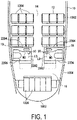
FIG. 1 is a plan view illustrating the relationship between an aircraft lavatory unit installed in an aircraft, an aisle, and a group of seats. -
FIG. 2 is a perspective view of an aircraft lavatory unit. -
FIG. 3 is a perspective view of the aircraft lavatory unit in which one frame side wall and a door are omitted. -
FIG. 4 is a perspective view of the aircraft lavatory unit in which an opening/closing plate that opens and closes a receiving chamber is omitted. -
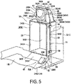
FIG. 5 is a perspective view of a portion of a floor pan and a waste compartment. -
FIG. 6 is a perspective view of a waste flap. -
FIG. 7 is a perspective view of a hinge mechanism that supports the waste flap. -
FIG. 8 is a side view of a lower portion of a connection mechanism and a foot pedal support mechanism in a state where the foot pedal is located at the upper limit position. -
FIG. 9 is a side view of a lower portion of a connection mechanism and a foot pedal support mechanism in a state where the foot pedal is located at the lower limit position. -
FIG. 10 is a perspective view of a lower portion of a connection mechanism and a foot pedal support mechanism in a state where the foot pedal is located at the upper limit position. -
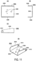
FIG. 11 is an explanatory drawing of a lower member that constitutes the foot pedal support mechanism, in which (A) is a plan view, (B) is a front view, (C) is a side view, and (D) is a perspective view. -
FIG. 12 is an explanatory diagram of an upper member that constitutes the foot pedal support mechanism, in which (A) is a plan view, (B) is a front view, (C) is a side view, and (D) is a perspective view. -
FIG. 13 is an explanatory view of an intermediate member that constitutes a foot pedal support mechanism, in which (A) is a plan view, (B) is a front view, (C) is a side view, and (D) is a perspective view. -
FIG. 14 is a front view of a support shaft that constitutes the foot pedal support mechanism. -
FIG. 15 is a perspective view of a lower arm that constitutes the connection mechanism. -
FIG. 16 is an explanatory view of a connecting member that constitutes a connection mechanism, in which (A) is a plan view and (B) is a front view. -
FIG. 17 is a side view of an upper portion of the connection mechanism and a waste flap swing mechanism in a state where the foot pedal is located at the upper limit position. -
FIG. 18 is a side view of an upper portion of the connection mechanism and the waste flap swing mechanism in a state where the foot pedal is located at the lower limit position. -
FIG. 19 is a perspective view of the waste flap swing mechanism as seen from the inside of the chute in which an expanded wall is omitted. -
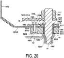
FIG. 20 is a cross-sectional view of a support shaft portion that constitutes the waste flap swing mechanism. -
FIG. 21 is a front view of an inner arm that constitutes the waste flap swing mechanism. -
FIG. 22 is an explanatory diagram of an engaging member that constitutes the waste flap swing mechanism, in which (A) is a front view and (B) is a side view. - Next, embodiments of the present invention will be described with reference to the drawings.
- As illustrated in
FIG. 1 ,seat groups 12 are provided in afuselage 10 of an aircraft, and additionally alongitudinal aisle 14 and alatitudinal aisle 16 are provided. - The front part of the
fuselage 10 is a control room and the rear part is apressure bulkhead 1002. - The
longitudinal aisle 14 extends in the longitudinal direction of thefuselage 10 at the center of thefuselage 10. - The
seat groups 12 are provided on both left and right sides of thelongitudinal aisle 14, and eachseat group 12 includes a plurality ofseat rows 1202 arranged in the longitudinal direction of thefuselage 10 and extending along thelongitudinal aisle 14. - Each
seat row 1202 includes a plurality ofseats 1204 arranged in the width direction of thefuselage 10 and facing the front of thefuselage 10. In the present embodiment, theseat row 1202 is configured by arranging threeseats 1204 in the horizontal direction. - The
latitudinal aisle 16 extends in the width direction of thefuselage 10 from aboarding gate 1004 at the rear of thefuselage 10 behind theseat row 1202 located at the rear end of theseat group 12, and is connected perpendicularly to thelongitudinal aisle 14. -
Galleys 1006 are provided at the front side of thepressure bulkhead 1002 and at the rear side of thelatitudinal aisle 16 and arranged in the width direction of thefuselage 10. - The
aircraft lavatory units 18 are disposed on both sides of thelongitudinal aisle 14 and at the rear side of theseat rows 1202 located at rear ends of therespective seat groups 12, and at the front side of thelatitudinal aisle 16. - As illustrated in
FIGS. 2 and3 , thebody frame 20 of theaircraft lavatory unit 18 includes a plurality offrame walls 22 forming alavatory 18A. Theframe walls 22 include aframe bottom wall 2202, a firstframe side wall 2204 and a secondframe side wall 2206 facing each other and standing parallel to each other from theframe bottom wall 2202, a framerear wall 2208 connecting one set of ends of theside walls frame front wall 2210 connecting the other set of ends of theside walls frame ceiling wall 2212. - As illustrated in
FIG. 1 , the firstframe side wall 2204 is disposed adjacent to theseat row 1202 located at the rear end behind theseat row 1202 located at the rear end of theseat group 12, and the secondframe side wall 2206 is disposed by facing thelatitudinal aisle 16. - As illustrated in
FIGS. 1 and2 , anentrance 2002 is provided in theframe front wall 2210. Theentrance 2002 is constituted by anopening 2004 formed in theframe front wall 2210 and adoor 2006 that opens and closes theopening 2004. Thefront wall 2210 provided with theentrance 2002 is disposed to face thelongitudinal aisle 14. - As illustrated in
FIG. 3 , afloor 18B of thelavatory 18A is formed on the upper surface of thefloor pan 24 placed on theframe bottom wall 2202, and atoilet bowl 26, asink 28, and a waste disposal device 30 (seeFIG. 4 ) are disposed in thelavatory 18A. - The
floor pan 24 includes abottom portion 2402 that constitutes thefloor 18B of thelavatory 18A, and aside surface portion 2404 standing from the periphery of thebottom surface portion 2402. - The
toilet bowl 26 is disposed in front of the framerear wall 2208, and thesink 28 is provided on the upper surface of a base 2802 installed inside the firstframe side wall 2204. Thesink 28 includes acounter 2804, afaucet 2806, ahand wash bowl 2808, and amirror 2810. - As illustrated in
FIG. 4 , a receivingchamber 2812 in which thewaste disposal device 30 is received is provided inside thebase 2802 on thefloor 18B. - As illustrated in
FIG. 3 , a portion of the wall portion that partitions the receivingchamber 2812 and extends below thesink 28 is provided as an opening/closing plate 32 that opens and closes the receivingchamber 2812 below thesink 28. Oneside portion 3202 in the width direction of the opening/closing plate 32 swings by using a hinge as a fulcrum. - A
trash feeding port 3204 is formed and ahousing portion 3206 for toilet paper is formed, in the upper portion of the opening/closing plate 32. - In addition, in a state in which the
receiving chamber 2812 is closed by the opening/closing plate 32, a latch with alock 3208 that engages with the striker on thebase 2802 side is provided on the other side in the width direction of the opening/closing plate 32. For prevention of mischief and terrorism, the opening/closing plate 32 has a structure that cannot be easily opened. - The
waste disposal device 30 configured by including awaste compartment assembly 3002 illustrated inFIGS. 4 and5 , apressure plate 3210 provided on the opening/closing plate 32 illustrated inFIG. 8 , and afire extinguisher 3004 illustrated inFIGS. 4 and5 . - The
waste compartment assembly 3002 includes awaste compartment 34, awaste container 36, achute 38 and awaste flap 40. - The
waste compartment 34, thewaste container 36, thechute 38, thewaste flap 40, and thepressure plate 3210 are formed of fire-resistant materials, and metal materials represented by aluminum, a flame-retardant resin or the like can be used as such a material, for example. - As illustrated in
FIG. 5 , thewaste compartment 34 includes acompartment bottom wall 3402, a compartmentrear wall 3404 standing from the end of thecompartment bottom wall 3402 near the firstframe side wall 2204, a compartmentupper wall 3406 facing thecompartment bottom wall 3402 below thecounter 2804, andcompartment side walls 3408 on both sides that connect both edges of thecompartment bottom wall 3402, the compartmentrear wall 3404, and the compartmentupper wall 3406. Anopening portion 3410 for inserting and removing thewaste container 36 is provided on thelavatory 18A side of thewaste compartment 34. - A plurality of sections of the compartment
rear wall 3404 are attached to the firstframe side wall 2204 with screws. Moreover, a plurality of sections of thecompartment side wall 3408A located on the side of theframe front wall 2210 are attached to theframe front wall 2210 with screws with spacers interposed therebetween. In this way, thewaste compartment 34 is disposed in the receivingchamber 2812, thecompartment bottom wall 3402 is located at a section upwardly separated from theframe bottom wall 2202, and anopening portion 3410 faces the secondframe side wall 2206. - A
compartment side wall 3408A is disposed adjacent to theframe front wall 2210, and a small gap S is provided between thecompartment side wall 3408A and theframe front wall 2210. - The gap S is covered with the
counter 2804, and the space S is covered with respect to the inside of thelavatory 18A in a state in which thereceiving chamber 2812 is closed by the opening/closing plate 32. - As illustrated in
FIG. 5 , thechute 38 is erected on the compartmentupper wall 3406. - The
chute 38 includes achute front wall 3802 located on the opening/closing plate 32 side,chute side walls 3804 on both sides, a chuterear wall 3806 located near the firstframe side wall 2204 and a chuteupper wall 3808. These walls are formed of a thin plate material, and the chuterear wall 3806 and the chuteupper wall 3808 are formed of a single plate material. - A
trash feeding opening 3810 is formed at a section of thechute front wall 3802 corresponding to thetrash feeding port 3204 of the opening/closing plate 32. - In
FIG. 5 ,reference numerals chute front wall 3802 and thechute side wall 3804 which are attached to the compartmentupper wall 3406 of thewaste compartment 34 with screws.Reference numerals chute front wall 3802 and the chuterear wall 3806 which are attached to thechute side wall 3804 with screws. - The width between the
chute side walls 3804 on both sides is the minimum dimension sufficient to swing thewaste flap 40. - One
chute side wall 3804A of thechute side walls 3804 on both sides is disposed adjacent to theframe front wall 2210. An expandedwall 3804B, in which the width between thechute side walls 3804 on both sides is widened, is provided so that aninner arm 74 of the wastestrap swing mechanism 54, which will be described later, is disposed above thechute side wall 3804A near theframe front wall 2210. - The internal space of the
chute 38 communicates with the internal space of thewaste compartment 34 through an opening (not illustrated) provided in the compartmentupper wall 3406. - The
fire extinguisher 3004 is provided on the compartmentupper wall 3406. - The
fire extinguisher 3004 injects a fire-extinguishing agent from the injection nozzle toward the inside of thewaste container 36 housed in thewaste compartment 34 when a temperature is reached at a set temperature or more. A known inert gas, such as chlorofluorocarbon gas or halon gas, can be used as the fire-extinguishing agent, and a commercially available product can be used for thefire extinguisher 3004. - The
waste flap 40 opens and closes thetrash feeding opening 3810, and can swing between a closed position for closing thetrash feeding opening 3810 as illustrated inFIG. 17 and an opened position for opening thetrash feeding opening 3810 as illustrated inFIG. 18 . - As illustrated in
FIG. 6 , thewaste flap 40 includes arectangular board portion 4002 andflanges 4004 standing from four sides of theboard portion 4002. An expandedportion 4006 inserted into thetrash feeding opening 3810 is formed at the center of theboard portion 4002. - As illustrated in
FIGS. 3 and17 , when thewaste flap 40 is in the closed position, the expandedportion 4006 is inserted into thetrash feeding opening 3810 and thetrash feeding port 3204 of the opening/closing plate 32 and protrudes outside thechute 38 and the opening/closing plate 32, and the outer surface of theboard portion 4002 abuts against the inner surface of thechute front wall 3802. - With the receiving
chamber 2812 closed by the opening/closing plate 32, theopening portion 3410 of thewaste compartment 34 is closed by thepressure plate 3210 provided on the opening/closing plate 32. In this state, when thetrash feeding opening 3810 is closed by thewaste flap 40, a fire spreading prevention space that satisfies the Fire Containment requirements specified in United States Federal Aviation Regulations (FAR) 25.853 is formed from thechute 38 to thewaste compartment 34. Thus, when trash fed into thetrash feeding opening 3810 burns, spreading of fire to the outside of thewaste compartment assembly 3002 is prevented. - As illustrated in
FIG. 6 , theflange 4004A disposed in the upper portion is formed to have a longer protruding length than theflanges 4004 provided at other sections. As illustrated inFIG. 7 , ahinge mechanism 42 is provided to swingably support thewaste flap 40 between theflange 4004A and the chuteupper wall 3808. Moreover, atorsion spring 44 is provided to constantly bias thewaste flap 40 in the direction of closing thetrash feeding opening 3810. - The
hinge mechanism 42 is constituted by two hinges, and each hinge is constituted by a pair of hinge pieces 4204A and 4204B that are swingably coupled with thesupport shaft 4202. - Two torsion springs 44 are provided and attached to the
support shafts 4202 of thehinge mechanisms 42. - One hinge piece 4204A of the pair of hinge pieces 4204A and 4204B of each hinge is attached to the lower surface of the chute
upper wall 3808, and the other hinge piece 4204B is attached to the lower surface offlange 4004A. In this way, thewaste flap 40 is swingably provided on thechute 38 via thehinge mechanism 42, and is constantly biased in the direction of closing thetrash feeding opening 3810 by thetorsion spring 44. - As illustrated in
FIGS. 6 ,17 , and18 , in a state where thewaste flap 40 is assembled into thechute 38 via thehinge mechanism 42, anattachment piece 4008 is erected from the inner surface of theboard portion 4002 at a section close to theflange 4004 located on theframe front wall 2210 side. - As indicated by an imaginary line in
FIG. 6 , an engagedpin 46 is provided as an engaged portion protruding toward thechute side wall 3804A through a hole 4010 at the tip of theattachment piece 4008. - The engaged
pin 46 is attached by inserting amale thread portion 4602 protruding from the base portion of the engagedpin 46 into the hole 4010 at the tip of theattachment piece 4008 and screwing a nut (not illustrated) onto themale thread portion 4602. - Next, a foot pedal-type waste flap opening/
closing mechanism 48 will be described. - As illustrated in
FIGS. 3 and4 , the foot pedal-type waste flap opening/closing mechanism 48 swings thewaste flap 40 from the closed position to the opened position by stepping on thefoot pedal 50 on thefloor 18B. - The foot pedal-type waste flap opening/
closing mechanism 48 includes a footpedal support mechanism 52 illustrated inFIGS. 8 and9 , a wasteflap swing mechanism 54 illustrated inFIGS. 17 and18 , and aconnection mechanism 56 illustrated inFIG. 5 . - As illustrated in
FIGS. 8 and9 , the footpedal support mechanism 52 includes alower member 5202, asupport shaft 5220, and atorsion spring 5230 illustrated inFIG. 10 . - The foot
pedal support mechanism 52 swingably supports thefoot pedal 50 between an upper limit position illustrated inFIG. 8 where thefoot pedal 50 can be stepped on and a lower limit position illustrated inFIG. 9 where thefoot pedal 50 is stepped on from the upper limit position, and biases thefoot pedal 50 allowing the foot pedal to be positioned at the upper limit position. - The
foot pedal 50 is disposed close to a section directly below thewaste compartment 34. - The
foot pedal 50 includes a foot pedalfront end 50A away from thewaste compartment 34 and a foot pedalrear end 50B disposed directly below thewaste compartment 34. - The foot
pedal support mechanism 52 is configured such that, at the upper limit position, thefoot pedal 50 is inclined and supported so that the foot pedalrear end 50B is located above the foot pedalfront end 50A, and the foot pedalrear end 50B swings in the vertical direction by using the foot pedalfront end 50A as a fulcrum. - As illustrated in the plan view of
FIG. 1 , thefoot pedal 50 has a longitudinal direction LD along a direction connecting the foot pedalfront end 50A and the foot pedalrear end 50B and a width direction WD along a direction orthogonal to the longitudinal direction LD. - The longitudinal direction LD of the
foot pedal 50 extends in the extension direction of theseat group 12, which is the direction in which theseat rows 1202 are arranged, and the width direction WD of thefoot pedal 50 extends in a direction orthogonal to the extension direction of thelongitudinal aisle 14. - As illustrated in
FIG. 8 , thefoot pedal 50 includes anupper member 5002, anintermediate member 5030, and adecorative plate 5080. - The
upper member 5002, theintermediate member 5030, and thelower member 5202 constituting the footpedal support mechanism 52 are formed of metal or synthetic resin. Thesupport shaft 5220 and thetorsion spring 5230 constituting the footpedal support mechanism 52 are formed of metal. - The
lower member 5202 is disposed on thebottom surface portion 2402 of thefloor pan 24 close to a section directly below thewaste compartment 34. - As illustrated in
FIG. 11 , thelower member 5202 includes alower surface portion 5204 placed on thebottom surface portion 2402 of thefloor pan 24 and lowerside surface portions 5206 that stand from both sides of thelower surface portion 5204. - A plurality of
bolt insertion holes 5208 is formed in thelower surface portion 5204. - As illustrated in
FIG. 8 , thelower surface portion 5204 is placed on thebottom surface portion 2402 of thefloor pan 24 and attached to theframe bottom wall 2202 bybolts 5210 inserted through the bolt insertion holes 5208. - By providing the
lower member 5202 constituting the footpedal support mechanism 52 on thebottom surface portion 2402 of thefloor pan 24 in this manner, it is designed to be easily applied to an existingaircraft lavatory unit 18. - As illustrated in
FIG. 8 , the height of the upper edge of the lowerside surface portion 5206 is formed to be the lowest at the front end away from thewaste compartment 34 and gradually increases as it approaches a section directly below thewaste compartment 34, and the rear end located directly below thewaste compartment 34 is formed to be the highest. - Support
shaft insertion holes 5212 are formed at the front ends of the lowerside surface portions 5206 on both sides away from thewaste compartment 34, and thesupport shafts 5220 are inserted through the support shaft insertion holes 5212. - As illustrated in
FIG. 8 , theintermediate member 5030 is attached to the lower surface of theupper member 5002, and theupper member 5002 swings together with theintermediate member 5030 about thesupport shaft 5220 between the upper limit position and the lower limit position as a center. - As illustrated in
FIG. 12 , theupper member 5002 includes anupper surface portion 5004 and upperside surface portions 5006 extending vertically from both sides of theupper surface portion 5004. - The
upper surface portion 5004 has an elongated shape whose length is greater than its width, and the upperside surface portions 5006 are provided on both sides of theupper surface portion 5004 in the width direction. - The width and length of the
upper surface portion 5004 and the dimension between theupper surface portions 5006 on both sides are larger than the width and length of thelower surface portion 5204 of thelower member 5202 and the dimension between the lowerside surface portions 5206 on both sides. Theupper surface portion 5004 has such a dimension that theupper surface portion 5004 covers thelower surface portion 5204 from the upper side covering the footpedal support mechanism 52 including thelower member 5202. - As illustrated in
FIG. 8 , the downward protruding length of the lower edge of the upperside surface portion 5006 is the shortest at the front end away from thewaste compartment 34, and gradually increase as it approaches thewaste compartment 34, and the length is the largest at the rear end located directly below thewaste compartment 34. - As illustrated in
FIG. 12 , a plurality of taperedholes 5008 for receiving the heads of screws for attaching theintermediate member 5030 to the lower surface of theupper surface portion 5004 is formed in theupper surface portion 5004. - An
inclined surface portion 5010 that is gradually inclined downward as it moves away from theupper surface portion 5004 is provided at the front end of theupper surface portion 5004 away from thewaste compartment 34. - As illustrated in
FIGS. 8 and9 , thedecorative plate 5080 is provided on theupper surface portion 5004. - The
decorative plate 5080 is formed of a material having a large coefficient of friction against the shoe sole, which is rubber or synthetic resin for example, and is attached to theupper surface portion 5004 using an adhesive, screws, or the like. - In the present embodiment, the
decorative plate 5080 is a section of thefoot pedal 50 that is stepped on by the shoe sole, and theupper surface portion 5004 is a section that is stepped on via thedecorative plate 5080. - Although the
decorative plate 5080 may be omitted, the provision of thedecorative plate 5080 is advantageous in improving the operability of stepping on thefoot pedal 50, and in improving the appearance of the foot pedal-type waste flap opening/closing mechanism 48. - As illustrated in
FIG. 13 , theintermediate member 5030 includes, an intermediateupper surface portion 5042 and intermediateside surface portions 5044 vertically provided from both sides of the intermediateupper surface portion 5042. - The intermediate
upper surface portion 5042 has an elongated shape whose length is greater than its width, and the intermediateside surface portions 5044 are provided on both sides of the intermediateupper surface portion 5042 in the width direction. - The length of the intermediate
upper surface portion 5042 is formed to be larger than the length of thelower surface portion 5204 of thelower member 5202. - The width of the intermediate
upper surface portion 5042 and the dimension between the intermediateside surface portions 5044 on both sides are formed to be smaller than the width of thelower surface portion 5204 of thelower member 5202 and the dimension between the lowerside surface portions 5206 on both sides. - A protruding
portion 5046 protruding toward the framerear wall 2208 is provided at the end on the framerear wall 2208 side, in the intermediateside surface portion 5044 disposed on theframe front wall 2210 side among the pair of intermediateside surface portions 5044, and a connectingpin insertion hole 5048 is formed in the protrudingportion 5046. - An
inclined surface portion 5050 that is gradually inclined downward as it moves away from the intermediateupper surface portion 5042 is provided at the front end of the intermediateupper surface portion 5042 away from thewaste compartment 34. - A plurality of
screw insertion holes 5052 is formed in the intermediateupper surface portion 5042 that allows attachment to theupper surface portion 5004 of theupper member 5002. - As illustrated in
FIG. 8 , theintermediate member 5030 is attached to theupper surface portion 5004 by overlaying the upper surface of the intermediate upper surface portion 5042 (seeFIG. 13 ) on the lower surface of the upper surface portion 5004 (seeFIG. 12 ) of theupper member 5002, inserting thescrew 5054 into the taperedhole 5008 and thescrew insertion hole 5052, and coupling thenut 5056 with the male thread of thescrew 5054 protruding from the lower surface of the intermediateupper surface portion 5042 as illustrated inFIG. 10 . In this way, theupper member 5002 and theintermediate member 5030 are integrated. - As illustrated in
FIG. 13 , a supportshaft insertion holes 5058 is formed at the front ends of the pair of intermediateside surface portions 5044 away from thewaste compartment 34. - The integrated
intermediate member 5030 andupper member 5002 are put on thelower member 5202 from above, and in this state, as illustrated inFIG. 10 , each of the pair of lowerside surface portions 5206 of thelower member 5202 is located between the intermediateside surface portion 5044 of theintermediate member 5030 and the upperside surface portion 5006 of theupper member 5002. - The
support shaft 5220 illustrated inFIG. 14 is inserted through the support shaft insertion hole 5212 (seeFIG. 11(C) ) of thelower member 5202 and the support shaft insertion hole 5058 (seeFIG. 13(C) ) of theintermediate member 5030, and an E-ring (not illustrated) is attached to agroove 5222 of thesupport shaft 5220 protruding from the lowerside surface portion 5206 of thelower member 5202 whereby theintermediate member 5030 is swingably connected to thelower member 5202 via thesupport shaft 5220. In other words, thefoot pedal 50 is swingably connected to thelower member 5202. - The
torsion spring 5230 is hooked on the portion of thesupport shaft 5220 located on the lower surface of the intermediateupper surface portion 5042 of theintermediate member 5030, and the rear end of theintermediate member 5030 located directly below thewaste compartment 34 is constantly biased upward by using thesupport shaft 5220 as a fulcrum. - In a state where the
foot pedal 50 is supported by the footpedal support mechanism 52 in this manner, theupper member 5002 covers thelower member 5202, thesupport shaft 5220, and thetorsion spring 5230 together with the intermediate member 5040. That is, theupper member 5002 covers the footpedal support mechanism 52. Thus, it is advantageous in improving the operability of stepping on thefoot pedal 50, improving the appearance of the foot pedal-type waste flap opening/closing mechanism 48, and preventing troubles such as shoes getting caught under thefoot pedal 50. - As illustrated in
FIG. 8 , thefoot pedal 50 is configured such that the tip of theinclined surface portion 5050 of theintermediate member 5030 abuts the tip of thelower surface portion 5204 of thelower member 5202 so that thefoot pedal 50 is at the upper limit position where the end of theupper member 5002 away from thesupport shaft 5220 is at the highest position. And thus thefoot pedal 50 is constantly biased by thetorsion spring 5230 allowing the foot pedal to be located at the upper limit position. - The
foot pedal 50 is configured such that the foot pedalrear end 50B moves down by stepping on thedecorative plate 5080 with the shoe sole and the lower surface of theupper surface portion 5004 of theupper member 5002 abuts the upper edge of the pair of the lowerside surface portions 5206 of thelower member 5202, whereby thefoot pedal 50 is at the lower limit position where the foot pedalrear end 50B is at the lowest position. - Accordingly, the foot
pedal support mechanism 52 is configured such that, at the upper limit position, thefoot pedal 50 is supported being inclined so that the foot pedalrear end 50B located directly below thewaste compartment 34 is located above the foot pedalfront end 50A away from thewaste compartment 34, and the foot pedalrear end 50B swings downward by using the foot pedalfront end 50A as a fulcrum by stepping on thefoot pedal 50. - Further, in the present embodiment, as illustrated in
FIG. 8 , the foot pedalrear end 50B is located below thewaste compartment 34 and the opening/closing plate 32 that closes the receivingchamber 2812 and theopening portion 3410 of thewaste compartment 34. In a plan view, the foot pedalrear end 50B overlaps at least the contour of the opening/closing plate 32 in a state in which thereceiving chamber 2812 and theopening portion 3410 are closed. - Next, the
connection mechanism 56 that connects the footpedal support mechanism 52 and the wasteflap swing mechanism 54 will be described. - As illustrated in
FIG. 5 , theconnection mechanism 56 includes alower arm 58, a connectingmember 60, anouter arm 62, and arotating shaft 64. - As illustrated in
FIGS. 8 to 10 , thelower arm 58 is extending below thewaste compartment 34 and swings integrally with thefoot pedal 50. - As illustrated in
FIGS. 5 and15 , thelower arm 58 includes a firstlongitudinal portion 5802 connected to thefoot pedal 50 and extending in the longitudinal direction of thefoot pedal 50 through anotch 2406 of theside surface portion 2404 of thefloor pan 24 to reach below thewaste compartment 34, alateral portion 5804 extending from the firstlongitudinal portion 5802 directly downward below the gap S, and a secondlongitudinal portion 5806 extending from the end of thelateral portion 5804 directly below the gap S in a direction away from thefoot pedal 50 in parallel to the firstlongitudinal portion 5802. - As illustrated in
FIG. 8 , the tip of the firstlongitudinal portion 5802 is swingably connected to the protrudingportion 5046 of theintermediate member 5030 via an E-ring (not illustrated) and a connectingpin 5810 which is inserted through a connecting pin insertion hole 5808 (seeFIG. 15 ) provided at the tip of the firstlongitudinal portion 5802 and a connecting pin insertion hole 5048 (seeFIG. 13(C) ) of the protrudingportion 5046 of theintermediate member 5030. - The tip of the second
longitudinal portion 5806 is connected to the lower end of the connectingmember 60 by a plurality ofscrews 5814 that passes through a plurality ofscrew insertion holes 5812 provided at the tip of the secondlongitudinal portion 5806. Accordingly, the lower end of the connectingmember 60 is connected to the footpedal support mechanism 52 via thelower arm 58. - By providing the
lower arm 58 in this manner, it is advantageous in easily connecting the footpedal support mechanism 52 and theconnection mechanism 56. - As illustrated in
FIGS. 5 and16 , the connectingmember 60 is formed of a narrow plate material having a uniform thickness and a uniform width. The connectingmember 60 includes alower portion 6002 extending through the gap S in the vertical direction and anupper portion 6004 that rises from the upper end of thelower portion 6002 while approaching thelavatory 18A side. - A plurality of
screw holes 6006 into which the screws 5814 (seeFIG. 8 ) are screwed is provided at the lower end of thelower portion 6002, andattachment holes 6010 are provided at the tip of theupper portion 6004. - As illustrated in
FIGS. 5 ,8 , and9 , guides 66, includingguide grooves 6602 for guiding thelower portion 6002 of the connectingmember 60 are attached bybolts 6604 to the upper and lower portions of thecompartment side wall 3408A disposed on theframe front wall 2210 side. - The
guide groove 6602 is formed as a long groove whose length is greater than its width. - The width of the
guide groove 6602 is slightly larger than the thickness of the connectingmember 60 so that thelower portion 6002 can slide up and down inside theguide groove 6602. - The
guide groove 6602 is formed in a dimension to have such a length that thelower portion 6002 of the connectingmember 60 is close to one end of theguide groove 6602 in the longitudinal direction at the upper limit position of thefoot pedal 50 as illustrated inFIG. 8 , and thelower portion 6002 of the connectingmember 60 is close to the other end of theguide groove 6602 in the longitudinal direction at the lower limit position of thefoot pedal 50 as illustrated inFIG. 9 . - In an aircraft, the fuselage is subject to vibrations during take-off, landing, and flight. However, since the connecting
member 60 is long, this vibration causes a large inertial force to act on the connectingmember 60. Accordingly, providing theguide 66 allows for the inertial force of the connectingmember 60 due to this vibration being prevented from directly transmitted to thetorsion spring 44 and thehinge mechanism 42 that supports thewaste flap 40, and the durability of thehinge mechanism 42 and thetorsion spring 44 being not adversely affected. - As illustrated in
FIGS. 5 ,17 and18 , the base portion of theouter arm 62 is attached to and integrally rotatable with the rotatingshaft 64 disposed above thechute 38. The tip portion of theouter arm 62 and an upper end of theupper portion 6004 of the connectingmember 60 are rotatably connected via an E-ring 6204 and apin 6202 inserted through an attachment hole (not illustrated) of theouter arm 62 and an attachment hole 6010 (seeFIG. 16(A) ) of theupper portion 6004. - As illustrated in
FIG. 5 , the rotatingshaft 64 is disposed in an expandedwall 3804B of the upper portion of thechute side wall 3804A, and as illustrated inFIG. 20 , is inserted through ahole 3812 of the expandedwall 3804B and extends across the interior and exterior of thechute 38. - The rotating
shaft 64 includes an outermale thread portion 6402, anintermediate shaft portion 6404 continuous to the outermale thread portion 6402, a large-diameter portion 6406 provided in a section near the end of theintermediate shaft portion 6404, and an innermale thread portion 6408 continuous to the end of theintermediate shaft portion 6404. - The rotating
shaft 64 is rotatably supported by the expandedwall 3804B via anouter bracket 68 disposed on the outer surface of the expandedwall 3804B and aninner bracket 70 disposed on the inner surface of the expandedwall 3804B. - As illustrated in
FIGS. 17 and18 , theouter bracket 68 has an elongated shape in the horizontal direction. As illustrated inFIG. 20 , aninsertion hole 6802 through which theintermediate shaft portion 6404 is inserted is provided at the center in the longitudinal direction thereof. Abearing 6804 such as a metal bearing or a rolling bearing is disposed in theinsertion hole 6802, and theintermediate shaft portion 6404 is rotatably supported by thebearing 6804. - A
housing recess 6808 for housing the head of thebolt 6806, and abolt insertion hole 6810 passing through the bottom surface of thehousing recess 6808 are provided at both ends of theouter bracket 68 in the longitudinal direction. - The
inner bracket 70 has a disc shape. As illustrated inFIG. 20 , aninsertion hole 7002 through which theintermediate shaft portion 6404 is inserted is provided at the center thereof. Abearing 7004 such as a metal bearing or a rolling bearing is disposed in theinsertion hole 7002, and theintermediate shaft portion 6404 is rotatably supported by thebearing 7004. - In the present embodiment, a metal bearing is used as the
bearing 7004, and the metal bearing includes a cylindrical portion that rotatably supports theintermediate shaft portion 6404, and acollar portion 7006 that extends in an annular plate shape from the end of the cylindrical portion. - The
collar portion 7006 contacts the inner surface of theinner bracket 70 and the outer surface of the large-diameter portion 6406 of therotating shaft 64 allowing the rotatingshaft 64 to rotate smoothly. -
Bolt insertion holes 7008 are provided at sections each corresponding to thebolt insertion holes 6810 of theouter bracket 68 on the outer peripheral portion of theinner bracket 70. As illustrated inFIG. 19 , abolt insertion hole 7010 is provided in the upper and lower portions of the outer peripheral portion of theinner bracket 70. - As illustrated in
FIG. 20 , theouter bracket 68 is overlaid on the outer surface of the expandedwall 3804B, theinner bracket 70 is overlaid on the inner surface of the expandedwall 3804B, thebolt 6806 is inserted through thebolt insertion hole 7008 of theinner bracket 70 while passing through thebolt insertion hole 3814 of the expandedwall 3804B from thebolt insertion hole 6810 and thehousing recess 6808 of theouter bracket 68, and thenut 7012 is fastened to the male thread of thebolt 6806 protruding from theinner bracket 70. Thebolt 6806 and thenut 7012 constitute afirst fastener 7014, and thefirst fastener 7014 attaches theouter bracket 68 and theinner bracket 70 to the expandedwall 3804B. - That is, the rotating
shaft 64 is not supported by brackets provided on either the inner surface or the outer surface of the expandedwall 3804B, but is supported by brackets provided on both surfaces of the expandedwall 3804B, and the brackets receive the reaction force received by the expandedwall 3804B when thewaste flap 40 swings in a distributed manner and firmly support the rotatingshaft 64 allowing thewaste flap 40 to swing smoothly. - Further, as illustrated in
FIG. 19 , abolt 7016 is inserted throughbolt insertion holes 7010 in the upper and lower portions of theinner bracket 70 from a bolt insertion hole (not illustrated) of the expandedwall 3804B, and anut 7018 is fastened to a male thread of thebolt 7016 protruding from theinner bracket 70. Thebolt 7016 andnut 7018 constitute asecond fastener 7020, and thesecond fastener 7020 attaches theinner bracket 70 to the expandedwall 3804B at a section other than a section where theouter bracket 68 is attached to the expandedwall 3804B. - That is, when the
waste flap 40 swings, a larger load is applied to theinner bracket 70 than to theouter bracket 68. Accordingly, theinner bracket 70 is more firmly attached to the expandedwall 3804B allowing thewaste flap 40 to swing smoothly. - As illustrated in
FIG. 20 , theouter arm 62 is attached to integrally rotate with the rotatingshaft 64 in such a way that an outermale screw portion 6402 is inserted through anattachment hole 6206 in the base portion of theouter arm 62, theouter arm 62 abuts an annular end surface of a section at the boundary between the outermale screw portion 6402 and theintermediate shaft portion 6404, and theouter arm 62 is sandwiched between the annular end surface and anut 6208 screwed onto the outermale thread portion 6402. - An annular plate-shaped
slip member 6210 formed of a material having a small coefficient of friction with respect to theouter arm 62 and theouter bracket 68 is disposed on the outer peripheral portion of theintermediate shaft portion 6404 located between the base portion of theouter arm 62 and the outer surface of theouter bracket 68 allowing theouter arm 62 to swing smoothly. - The waste
flap swing mechanism 54 includes the engagedpin 46, which is an engaged portion, provided in thewaste flap 40, as illustrated inFIG. 6 , the rotatingshaft 64, as illustrated inFIG. 17 , and theinner arm 74 including theengagement portion 72 that is swingably supported inside thechute 38 via the rotatingshaft 64 and is detachably engaged with the engagedpin 46. - As illustrated in
FIG. 21 , theinner arm 74 includes acircular base portion 7402 and anextension portion 7404 extending linearly from thebase portion 7402. - The
inner arm 74 is formed of a plate material having a uniform thickness, anattachment hole 7406 is formed in thebase portion 7402, anotch 7408 is formed in theextension portion 7404, and a plurality ofscrew holes 7410 is formed in the section of theextension portion 7404 where thenotch 7408 is formed. - As illustrated in
FIG. 19 , an engagingmember 76 including anengagement portion 72 is attached to the section of theextension portion 7404 where thenotch 7408 is formed. - As illustrated in
FIG. 22 , the engagingmember 76 includes anattachment plate portion 7602 that is detachably attached to theextension portion 7404 at a section provided with thenotch 7408, and a plate-shapedengagement portion 72 formed by bending from theattachment plate portion 7602. - The engaging
member 76 is formed of a material having a low coefficient of friction with respect to the engaged pin 46 (seeFIG. 17 ). - As illustrated in
FIG. 19 , the engagingmember 76 is attached to theinner arm 74 by screwing thescrew 7606 inserted through thescrew insertion hole 7604 of theattachment plate portion 7602 into thescrew hole 7410 of theextension portion 7404. With the engagingmember 76 attached in this manner, theengagement portion 72 covers the bottom portion of thenotch 7408. - As illustrated in
FIGS. 17 and18 , theengagement portion 72 extends linearly and is formed in an open shape in the direction in which thewaste flap 40 swings from the closed position to the opened position. - As illustrated in
FIG. 20 , the innermale thread portion 6408 of therotating shaft 64 is inserted through theattachment hole 7406 of theinner arm 74, thenut 7412 is screwed onto the innermale thread portion 6408, and thebase portion 7402 of theinner arm 74 is sandwiched between thenut 7412 and the large-diameter portion 6406 of therotating shaft 64. In this way, theinner arm 74 is attached to integrally rotate with the rotatingshaft 64. - The
outer arm 62 and theinner arm 74 are attached to therotating shaft 64 so that at the upper limit position of thefoot pedal 50, as illustrated inFIG. 17 , the engagedpin 46 is located near one end in the longitudinal direction of theengagement portion 72, and thewaste flap 40 is in the closed position, and at the lower limit position of thefoot pedal 50, as illustrated inFIG. 18 , the engagedpin 46 is located near the other end in the longitudinal direction of theengagement portion 72 and thewaste flap 40 is in the opened position. - By providing the
rotating shaft 64 penetrating the expandedwall 3804B in this way, it is advantageous in easily connecting theouter arm 62 constituting theconnection mechanism 56 and theinner arm 74 constituting the wasteflap swing mechanism 54. - Since the engaged
pin 46 contacts theengagement portion 72 and does not contact theinner arm 74, it is sufficient to replace the worn engagingmember 76 without replacing theinner arm 74 at maintenance, and it is advantageous in easily performing the maintenance work in a short time. - According to the
aircraft lavatory unit 18 of the present embodiment, stepping on thefoot pedal 50 brings thewaste flap 40 to the opened position opening thetrash feeding opening 3810 via theconnection mechanism 56 and the wasteflap swing mechanism 54, and trash can be thrown without using a hand. When the foot is released from thefoot pedal 50, thefoot pedal 50 is returned to the upper limit position by the footpedal support mechanism 52, and thewaste flap 40 returns to the closed position closing thetrash feeding opening 3810, and a fire spreading prevention space is formed from thechute 38 to thewaste container 36. - Further, the
foot pedal 50 is disposed close to thewaste compartment 34, and is disposed inclining such that the foot pedalfront end 50A away from thewaste compartment 34 at the upper limit position is located at a section lower than the foot pedalrear end 50B directly below thewaste compartment 34, and thus thefoot pedal 50 is formed to swing by using the section of the foot pedalfront end 50A as a fulcrum. - For this reason, compared with a case where the
foot pedal 50 is disposed such that the foot pedalfront end 50A is located at a section higher than the foot pedalrear end 50B at the upper limit position and thefoot pedal 50 swings by using the foot pedalrear end 50B as a fulcrum, it is advantageous in preventing troubles such as tripping over due to shoes getting caught at thefoot pedal 50 on thenarrow floor 18B of theaircraft lavatory unit 18. - Further, even if the
foot pedal 50 is disposed, it is advantageous in preventing troubles such as tripping over thefoot pedal 50, which is advantageous in arranging thefoot pedal 50 without impairing the usability in thelavatory 18A. - Further, when the
foot pedal 50 is configured such that the foot pedalfront end 50A away from thewaste compartment 34 is the highest, and thefoot pedal 50 swings by using the lowest section of the foot pedalrear end 50B directly below thewaste compartment 34 as a fulcrum, thefoot pedal 50 is likely to be stepped on with the whole weight, and an excessive load is likely to be applied to the footpedal support mechanism 52, the wasteflap swing mechanism 54, and theconnection mechanism 56. - On the other hand, the
foot pedal 50 of the present embodiment is disposed close to thewaste compartment 34 and is configured such that the foot pedalfront end 50A away from thewaste compartment 34 is the lowest, and thefoot pedal 50 swings by using the section of the foot pedalfront end 50A as a fulcrum, it is easy to guide thefoot pedal 50 being stepped on with the heel on thefloor 50 of thelavatory 18A. - Accordingly, the
foot pedal 50 is not likely to be stepped on with the whole weight, and it is possible to prevent an excessive load from being applied to the footpedal support mechanism 52, the wasteflap swing mechanism 54, and theconnection mechanism 56, which is advantageous in enhancing the durability of the foot pedal-type waste flap opening/closing mechanism 48. - Further, the foot pedal
rear end 50B, which is located at the highest position, may be located on the outer side of the opening/closing plate 32 in a state in which thereceiving chamber 2812 is closed in a plan view. However, in the present embodiment, the foot pedalrear end 50B is put under the opening/closing plate 32 and thewaste compartment 34, and in a plan view, the foot pedalrear end 50B overlaps at least the contour of the opening/closing plate 32 in a state where the receivingchamber 2812 is closed. - That is, a portion of the
foot pedal 50 located at the highest position is disposed outside thefloor 18B of thelavatory 18A used by the user. - Accordingly, compared with a case where the
entire foot pedal 50 is disposed exposing on thefloor 18B of thelavatory 18A, the area of thefloor 18B of thelavatory 18A can be increased. - Accordingly, it is more advantageous in preventing troubles such as the user of the
lavatory 18A tripping over thefoot pedal 50, and in improving the usability of theaircraft lavatory unit 18. - In addition, it becomes easier to guide the
foot pedal 50 being stepped on with the heel on thefloor 18B of thelavatory 18A, thus thefoot pedal 50 is less likely to be stepped on with the whole weight, and it is more advantageous in improving the durability of the foot pedal-type waste flap opening/closing mechanism 48. - Further, in the
waste disposal device 30 of theaircraft lavatory unit 18, from the viewpoint of emphasizing the fire spreading prevention space of thewaste disposal device 30, the durability is strictly required for thehinge mechanism 42 that swingably supports thewaste flap 40 and thetorsion spring 44 that biases thewaste flap 40 to the closed position. - Accordingly, it is necessary to add a foot pedal system not to affect the existing
hinge mechanism 42 andtorsion spring 44. - In the present embodiment, the engaged
pin 46 which is an engaged portion is provided in thewaste flap 40, theengagement portion 72 of theinner arm 74 of the wasteflap swing mechanism 54 is engaged with the engagedpin 46, and thewaste flap 40 swings from the closed position to the opened position. - In other words, when the
foot pedal 50 causes thewaste flap 40 to swing from the closed position to the opened position, the force for swinging the waste flaps 40 is not applied directly to thehinge mechanism 42, but the force is applied to the waste flaps 40. Accordingly, even if thewaste flap 40 is swung by thefoot pedal 50, the force acting on thesupport shaft 4202, the hinge pieces 4204A and 4204B, and thetorsion spring 44, which constitute thehinge mechanism 42 is identical to the force acting when pushing thewaste flap 40 with a hand and throwing trash. Accordingly, the durability of the existinghinge mechanism 42 andtorsion spring 44 is not affected. - The
engagement portion 72 for swinging thewaste flap 40 from the closed position to the opened position is formed in an opening-shape in the direction in which thewaste flap 40 swings from the closed position to the opened position. - Accordingly, even when the
foot pedal 50 is not stepped on by the foot, thewaste flap 40 can be swung from the closed position to the opened position by hand without any trouble, which is advantageous in improving the usability of thewaste disposal device 30. - In addition, the
waste flap 40 includes therectangular board portion 4002 and theflanges 4004 that stand up from four sides of thebase portion 4002. The four sides of thebase portion 4002 are reinforced by theflanges 4004 and are sections where the strength and rigidity are enhanced. - In the present embodiment, the engaged
pin 46 as an engaged portion is provided on one of the four sides of thebase plate portion 4002 via theattachment piece 4008, and thewaste flap 40 swings from the closed position to the opened position via the engagedpin 46. - Accordingly, since the force for swinging the
waste flap 40 acts on the sections where the strength and rigidity of thewaste flap 40 are enhanced, it is advantageous in enhancing the durability of thewaste flap 40 without affecting the durability of thewaste flap 40. - Further, in the
aircraft lavatory unit 18, the small gap S serving as a dead space is formed between thecompartment side wall 3408A, which is one of the pair ofcompartment side walls 3408 located on both sides of theopening portion 3410, and theframe front wall 2210 that partitions thelavatory 18A. - In the present embodiment, the connecting
member 60 extending in the vertical direction and connecting the footpedal support mechanism 52 and the wasteflap swing mechanism 54 is disposed in the gap S. Thus, it is advantageous in decreasing the number of sections to be processed when attaching the foot pedal-type waste flap opening/closing mechanism 48 of the present embodiment to the existingwaste disposal device 30 of theaircraft lavatory unit 18. Accordingly, it is possible to easily attach the foot pedal-type waste flap opening/closing mechanism 48, which is advantageous for cost reduction. - In addition, the
guides 66 that guides the connectingmember 60, elongated in the vertical direction, movably in the vertical direction are provided in a plurality of sections of thecompartment side wall 3408A spaced from each other in the vertical direction. Accordingly, the inertial force of the connectingmember 60 caused by the vibration of the fuselage received during take-off, landing, and flight is not allowed to be directly transmitted to thehinge mechanism 42 and thetorsion spring 44 that support thewaste flap 40. Moreover, the foot pedal-type waste flap opening/closing mechanism 48 is not allowed to affect the durability of thehinge mechanism 42 and thetorsion spring 44. - The
connection mechanism 56 includes thelower arm 58 that swings integrally with thefoot pedal 50, extends below thewaste compartment 34, and is connected to the lower end of the connectingmember 60, and thelower arm 58 is arranged through thenotch 2406 of theside surface portion 2404 of thefloor pan 24. Accordingly, thefoot pedal 50 and the connectingmember 60 can be connected by providing thenotch 2406 in theside surface portion 2404 of thefloor pan 24. Accordingly, it is advantageous in decreasing the number of sections to be processed when attaching the foot pedal-type waste flap opening/closing mechanism 48 to the existingwaste disposal device 30 of theaircraft lavatory unit 18, which is advantageous for cost reduction. - In addition, the
foot pedal 50 is disposed close to the section directly below thewaste compartment 34, and the footpedal support mechanism 52 is configured such that thefoot pedal 50 at the upper limit position is inclined and supported so that the foot pedalrear end 50B is located above the foot pedalfront end 50A, and the foot pedalrear end 50B swings in the vertical direction by using the foot pedalfront end 50A as a fulcrum. The longitudinal direction of thefoot pedal 50 extends in the extension direction of theseat group 12 which is the arrangement direction of theseat rows 1202. The width direction of thefoot pedal 50 extends in the direction orthogonal to the extension direction of thelongitudinal aisle 14. - Accordingly, even if the
foot pedal 50 is disposed, it is advantageous in preventing troubles such as tripping over thefoot pedal 50. It is not necessary to widen thefloor 18B of thelavatory 18A and increase the width and the length of theaircraft lavatory unit 18 in correspondence with the length and the width of thefoot pedal 50 in consideration of the usability in thelavatory 18A. Accordingly, it is advantageous in arranging thefoot pedal 50 without decreasing the number ofseat rows 1202 and narrowing thelongitudinal aisle 14. -
- 10 Fuselage
- 12 Seat group
- 1202 Seat row
- 1204 Seat
- 14 Longitudinal aisle
- 16 Latitudinal aisle
- 18 Aircraft lavatory unit
- 18A Lavatory
- 18B Floor
- 20 Body frame
- 2002 Entrance
- 22 Frame wall
- 2202 Frame bottom wall
- 2204 First frame side wall
- 2206 Second frame side wall
- 2210 Frame front wall
- 24 Floor pan
- 2402 Bottom surface portion
- 2404 Side surface portion
- 2406 Notch
- 28 Sink
- 2812 Receiving chamber
- 30 Waste disposal device
- 3002 Waste compartment assembly
- 3004 Fire extinguisher
- 32 Opening/closing plate
- 3204 Trash feeding port
- 34 Waste compartment
- 3402 Compartment bottom wall
- 3404 Compartment rear wall
- 3406 Compartment upper wall
- 3408 Compartment side wall
- 3410 Opening portion
- 36 Waste container
- 38 Chute
- 3802 Chute front wall
- 3804, 3804A Chute sidewall
- 3804B Expanded wall
- 3808 Chute upper wall
- 3810 Trash feeding opening
- 40 Waste flap
- 4002 Board portion
- 4004, 4004A Flange disposed on upper portion
- 4008 Attachment piece
- 42 Hinge mechanism
- 44 Torsion spring
- 46 Engaged pin (Engaged portion)
- 48 Foot pedal-type waste flap opening/closing mechanism
- 50 Foot pedal
- 50A Foot pedal front end
- 50B Foot pedal rear end
- 5002 Upper member
- 5040 Intermediate member
- 5050 Inclined surface portion
- 5080 Decorative plate
- 52 Foot pedal support mechanism
- 5202 Lower member
- 5220 Support shaft
- 5230 Torsion spring
- 54 Waste flap swing mechanism
- 56 Connection mechanism
- 58 Lower arm
- 60 Connecting member
- 6002 Lower portion
- 6004 Upper portion
- 62 Outer arm
- 64 Rotating shaft
- 66 Guide
- 68 Outer bracket
- 70 Inner bracket
- 7014 First fastener
- 7020 Second fastener
- 72 Engagement portion
- 74 Inner arm
- 76 Engaging member
Claims (15)
- A waste disposal device of an aircraft lavatory unit, comprising:a waste compartment provided on a floor of the aircraft lavatory unit installed in an aircraft and comprising an opening portion through which a waste container is taken in and out;a chute provided in an upper portion of the waste compartment and comprising a trash feeding opening formed; anda waste flap swingably supported by the chute between a closed position for closing the trash feeding opening and an opened position for opening the trash feeding opening and biased in a direction of closing the trash feeding opening;a foot pedal-type waste flap opening/closing mechanism that swings the waste strap from the closed position to the opened position by stepping on a foot pedal disposed close to a section on the floor directly below the waste compartment being provided,the foot pedal-type waste flap opening/closing mechanism comprising a foot pedal support mechanism that swingably supports the foot pedal between an upper limit position at which the foot pedal can be stepped on and a lower limit position at which the foot pedal is stepped on from the upper limit position and biases the foot pedal allowing the foot pedal to be located at the upper limit position, andthe foot pedal support mechanism being configured such that the foot pedal at the upper limit position is inclined and supported with a foot pedal rear end located directly below the waste compartment being located above a foot pedal front end that is away from the waste compartment and that the foot pedal rear end swings in a vertical direction by using the foot pedal front end as a fulcrum.
- The waste disposal device of the aircraft lavatory unit according to claim 1, whereinthe opening portion of the waste compartment is opened and closed by an opening/closing plate provided with a trash feeding port at a section corresponding to the trash feeding opening,a fire spreading prevention space is formed from the chute to the waste compartment in a state where the trash feeding opening is closed by the waste flap and the opening portion is closed by the opening/closing plate,lower ends of the waste compartment and the opening/closing plate are located at a section upwardly separated from the floor of the aircraft lavatory unit, andthe foot pedal rear end is located below the opening/closing plate in a state where the opening portion is closed, and the foot pedal rear end in a plan view overlaps a contour of the opening/closing plate in the state where the opening portion is closed.
- The waste disposal device of the aircraft lavatory unit according to claim 1 or 2, whereinthe foot pedal-type waste flap opening/closing mechanism further comprises a waste flap swing mechanism that engages with the waste flap and swings the waste flap from the closed position to the opened position,the waste flap swing mechanism comprises an inner arm comprising an engaged portion provided in the waste strap and an engagement portion that is swingably supported inside the chute and is detachably engaged with the engaged portion, andthe inner arm swings by stepping on the foot pedal, and the engagement portion engages with the engaged portion and swings the waste flap from the closed position to the opened position.
- The waste disposal device of the aircraft lavatory unit according to claim 3, wherein
the engagement portion is formed in an open shape in a direction of swing of the waste strap from the closed position to the opened position. - The waste disposal device of the aircraft lavatory unit according to claim 3 or 4, whereinan engaging member is detachably attached to the inner arm, andthe engagement portion is provided on the engaging member.
- The waste disposal device of the aircraft lavatory unit according to any one of claims 3 to 5, whereinthe foot pedal-type waste flap opening/closing mechanism further comprises a connection mechanism that connects the foot pedal support mechanism and the waste flap swing mechanism,the waste compartment comprises a pair of waste compartment side walls located on both sides of the opening portion,a body frame of the aircraft lavatory unit comprises a plurality of frame walls partitioning a lavatory,one waste compartment side wall of the pair of waste compartment side walls is disposed adjacent to one frame wall of the plurality of frame walls,the chute comprises a chute front wall provided with the trash feeding opening and a pair of chute side walls connected to the chute front wall,one chute side wall of the pair of chute side walls is disposed adjacent to the one frame wall,a rotating shaft is provided in an upper portion of the one chute side wall, the rotating shaft penetrating the chute side wall and rotatably supported by the chute side wall,the inner arm is attached to the rotating shaft and integrally rotates with the rotating shaft on an inner surface of the one chute side wall,the connection mechanism comprises an outer arm that is attached to the rotating shaft and allowed to integrally rotate with the rotating shaft on an outer surface of the one chute side wall and rotates the rotating shaft by stepping on the foot pedal.
- The waste disposal device of the aircraft lavatory unit according to claim 6, whereinan expanded wall expanding in a direction away from the other chute side wall is provided on an upper portion of the one chute side wall,the rotating shaft penetrates the expanded wall and is rotatably supported by the expanded wall,an outer bracket rotatably supporting a section of the rotating shaft located on an outer surface of the expanded wall is provided on the outer surface,an inner bracket rotatably supporting a section of the rotating shaft located on an inner surface of the expanded wall is provided on the inner surface, andthe outer bracket and the inner bracket are attached to the expanded wall by being fastened by a plurality of first fasteners penetrating the expanded wall and sandwiching the expanded wall.
- The waste disposal device of the aircraft lavatory unit according to claim 7, wherein
the inner bracket is further fastened to the expanded wall by a plurality of second fasteners different from the first fasteners. - The waste disposal device of the aircraft lavatory unit according to any one of claims 3 to 8, whereinthe waste flap comprises a rectangular board portion, four flanges standing from four sides of the board portion, and an expanded portion provided at a center of the board portion and inserted into the trash feeding opening,a hinge mechanism swingably supporting the waste flap and biasing the waste flap to the closed position is provided across one of the four flanges and a chute upper wall of the chute, andthe engaged portion is provided at a section of one side of the board portion on which another flange of the four flanges stands.
- The waste disposal device of the aircraft lavatory unit according to any one of claims 6 to 8, wherein
the connection mechanism comprises a connecting member disposed between one waste compartment side wall and the one frame wall, extending in a vertical direction, and comprising an upper end connected to the outer arm and a lower end connected to the foot pedal support mechanism. - The waste disposal device of the aircraft lavatory unit according to claim 10, wherein
a guide that guides the connecting member in a vertical direction is provided in a plurality of sections of the one waste compartment side wall spaced from each other in a vertical direction. - The waste disposal device of the aircraft lavatory unit according to claim 10 or 11, whereinthe connection mechanism comprises a lower arm that is connected to the foot pedal rear end, swings integrally with the foot pedal rear end, and extends below the waste compartment, anda lower end of the connecting member is connected to a tip of the lower arm.
- The waste disposal device of the aircraft lavatory unit according to claim 12, whereina body frame of the aircraft lavatory unit comprises a frame bottom wall,a floor pan is disposed on the frame bottom wall,the floor pan comprises a bottom surface portion constituting the floor of the aircraft lavatory unit and a side surface portion standing from a periphery of the bottom surface portion,the foot pedal support mechanism is disposed on the bottom surface portion, anda notch through which the lower arm protrudes toward a lower side of the waste compartment is provided in the side surface portion.
- The waste disposal device of the aircraft lavatory unit according to claim 12 or 13, whereinthe foot pedal support mechanism comprises a lower member placed on the bottom surface portion of the floor pan and attached to the frame bottom wall, a support shaft, and a torsion spring,the foot pedal comprises an intermediate member swingably coupled with the support shaft and biased to the upper limit position by the torsion spring and an upper member that is attached to the intermediate member, swings integrally with the intermediate member, and covers the lower member, the support shaft, and the torsion spring, andthe lower arm is connected to the intermediate member.
- The waste disposal device of the aircraft lavatory unit according to any one of claims 1 to 14, whereina fuselage of the aircraft comprises a longitudinal aisle extending in a longitudinal direction of the fuselage, a seat group configured by arranging seat rows in the longitudinal direction of the fuselage on both sides of the longitudinal aisle, and a latitudinal aisle provided behind the seat row located at a rear end of the seat group and orthogonal to the longitudinal aisle,the aircraft lavatory unit is provided between the latitudinal aisle and the seat row located at the rear end of the seat group,the body frame comprises a frame front wall provided with an entrance and facing the longitudinal aisle and a frame side wall adjacent to the seat row located at the rear end of the seat group,the waste compartment is provided on an inner surface of the frame side wall with the opening portion facing the latitudinal aisle,the foot pedal has a longitudinal direction along a direction of connecting the foot pedal front end and the foot pedal rear end and a width direction along a direction orthogonal to the longitudinal direction,the longitudinal direction of the foot pedal extends in a direction in which the seat rows are arranged, andthe width direction of the foot pedal extends in a direction orthogonal to an extension direction of the longitudinal aisle.
Applications Claiming Priority (2)
| Application Number | Priority Date | Filing Date | Title |
|---|---|---|---|
| JP2020072130A JP6911969B1 (en) | 2020-04-14 | 2020-04-14 | Trash can device for aircraft restroom unit |
| PCT/JP2021/000304 WO2021210222A1 (en) | 2020-04-14 | 2021-01-07 | Waste disposal device for aircraft lavatory unit |
Publications (3)
| Publication Number | Publication Date |
|---|---|
| EP4137408A1 true EP4137408A1 (en) | 2023-02-22 |
| EP4137408A4 EP4137408A4 (en) | 2024-05-15 |
| EP4137408B1 EP4137408B1 (en) | 2025-06-25 |
Family
ID=76968015
Family Applications (1)
| Application Number | Title | Priority Date | Filing Date |
|---|---|---|---|
| EP21788500.3A Active EP4137408B1 (en) | 2020-04-14 | 2021-01-07 | Waste disposal device for aircraft lavatory unit |
Country Status (4)
| Country | Link |
|---|---|
| US (1) | US11767118B2 (en) |
| EP (1) | EP4137408B1 (en) |
| JP (1) | JP6911969B1 (en) |
| WO (1) | WO2021210222A1 (en) |
Families Citing this family (3)
| Publication number | Priority date | Publication date | Assignee | Title |
|---|---|---|---|---|
| JP6607283B1 (en) * | 2018-05-31 | 2019-11-20 | 横浜ゴム株式会社 | Floor structure of aircraft restroom unit |
| CN119037700B (en) * | 2024-08-28 | 2025-11-07 | 中国直升机设计研究所 | Flat threshold maintenance channel structure and operation method |
| CN121376168B (en) * | 2025-12-22 | 2026-03-24 | 四川欧航科技有限责任公司 | Aircraft lavatory articles for use support |
Family Cites Families (8)
| Publication number | Priority date | Publication date | Assignee | Title |
|---|---|---|---|---|
| DE29602873U1 (en) * | 1996-02-17 | 1996-04-11 | Chang, Shang-Jen, Tou Nan Chen, Yun Lin | Waste bins, especially large waste bins with a door flap control |
| JP2007137671A (en) * | 2005-11-15 | 2007-06-07 | Noriko Motooka | Non-stinking garbage can and its deodorizing method |
| NL1031776C2 (en) * | 2006-05-09 | 2007-11-12 | Vendor Bv | Hygienic dressing waste bin. |
| EP2818411B1 (en) * | 2012-02-23 | 2018-09-26 | The Yokohama Rubber Company, Limited | Airplane lavatory unit and disposition configuration therefor |
| WO2017043177A1 (en) * | 2015-09-10 | 2017-03-16 | 横浜ゴム株式会社 | Waste bin device for aircraft lavatory unit |
| US10829219B2 (en) * | 2017-07-24 | 2020-11-10 | The Yokohama Rubber Co., Ltd. | Trash can device for aircraft lavatory unit |
| US10875707B2 (en) * | 2017-12-12 | 2020-12-29 | The Boeing Company | Trash compactor systems and methods |
| CN107867516A (en) * | 2017-12-12 | 2018-04-03 | 湖州罗芙科技有限公司 | A kind of multifunctional garbage apparatus for placing |
-
2020
- 2020-04-14 JP JP2020072130A patent/JP6911969B1/en active Active
-
2021
- 2021-01-07 US US17/995,807 patent/US11767118B2/en active Active
- 2021-01-07 WO PCT/JP2021/000304 patent/WO2021210222A1/en not_active Ceased
- 2021-01-07 EP EP21788500.3A patent/EP4137408B1/en active Active
Also Published As
| Publication number | Publication date |
|---|---|
| EP4137408A4 (en) | 2024-05-15 |
| US11767118B2 (en) | 2023-09-26 |
| EP4137408B1 (en) | 2025-06-25 |
| JP6911969B1 (en) | 2021-07-28 |
| JP2021169232A (en) | 2021-10-28 |
| WO2021210222A1 (en) | 2021-10-21 |
| US20230120725A1 (en) | 2023-04-20 |
Similar Documents
| Publication | Publication Date | Title |
|---|---|---|
| EP4137408B1 (en) | Waste disposal device for aircraft lavatory unit | |
| US5931415A (en) | Plug-type overwing emergency exit door assembly | |
| US9452837B2 (en) | Aircraft lavatory unit | |
| EP2686241B1 (en) | Plinth-mounted seat assembly and mounting sub-assemblies | |
| US9009880B2 (en) | Cover box for a shower flow system | |
| US20160355266A1 (en) | Module For An Aircraft Cabin With A Seat Fastened To A Door | |
| JP5478220B2 (en) | Wall-mounted folding chair | |
| US10822089B2 (en) | Waste bin device of aircraft lavatory unit | |
| EP2627216B1 (en) | Anchoring device for panels | |
| US11866975B2 (en) | Furniture drive | |
| JP6229757B2 (en) | Aircraft restroom unit | |
| US5593203A (en) | Retrofitted door for open luggage rack on passenger busses | |
| US20150197927A1 (en) | Anti-ligature flush valve cover | |
| US20090294585A1 (en) | Assembly for storing objects in the cabin of a vehicle | |
| US7173183B2 (en) | Combined fiber optic repeater/power source remote cabinet for distributed antenna systems | |
| CA2576303C (en) | Reinforced door | |
| CN213912053U (en) | Case is deposited to embedded fire extinguisher of upset | |
| JP7584291B2 (en) | booth | |
| GB2552767A (en) | Automatic opening vent | |
| JP7650620B2 (en) | Fittings | |
| US11370546B2 (en) | Crew rest compartment stair closure mechanism | |
| CN223508475U (en) | Sliding door with emergency pressure relief function for use on aircraft | |
| JP5407607B2 (en) | Game machine | |
| WO2019175541A1 (en) | Door locking device providing emergency access | |
| JP2001090425A (en) | Opening-section device |
Legal Events
| Date | Code | Title | Description |
|---|---|---|---|
| STAA | Information on the status of an ep patent application or granted ep patent |
Free format text: STATUS: THE INTERNATIONAL PUBLICATION HAS BEEN MADE |
|
| PUAI | Public reference made under article 153(3) epc to a published international application that has entered the european phase |
Free format text: ORIGINAL CODE: 0009012 |
|
| STAA | Information on the status of an ep patent application or granted ep patent |
Free format text: STATUS: REQUEST FOR EXAMINATION WAS MADE |
|
| 17P | Request for examination filed |
Effective date: 20221021 |
|
| AK | Designated contracting states |
Kind code of ref document: A1 Designated state(s): AL AT BE BG CH CY CZ DE DK EE ES FI FR GB GR HR HU IE IS IT LI LT LU LV MC MK MT NL NO PL PT RO RS SE SI SK SM TR |
|
| DAV | Request for validation of the european patent (deleted) | ||
| DAX | Request for extension of the european patent (deleted) | ||
| RAP3 | Party data changed (applicant data changed or rights of an application transferred) |
Owner name: THE YOKOHAMA RUBBER CO., LTD. |
|
| A4 | Supplementary search report drawn up and despatched |
Effective date: 20240415 |
|
| RIC1 | Information provided on ipc code assigned before grant |
Ipc: B65F 1/16 20060101ALI20240409BHEP Ipc: B65F 1/14 20060101ALI20240409BHEP Ipc: B64D 11/02 20060101AFI20240409BHEP |
|
| RAP3 | Party data changed (applicant data changed or rights of an application transferred) |
Owner name: THE YOKOHAMA RUBBER CO., LTD. |
|
| GRAP | Despatch of communication of intention to grant a patent |
Free format text: ORIGINAL CODE: EPIDOSNIGR1 |
|
| STAA | Information on the status of an ep patent application or granted ep patent |
Free format text: STATUS: GRANT OF PATENT IS INTENDED |
|
| INTG | Intention to grant announced |
Effective date: 20250128 |
|
| GRAS | Grant fee paid |
Free format text: ORIGINAL CODE: EPIDOSNIGR3 |
|
| GRAA | (expected) grant |
Free format text: ORIGINAL CODE: 0009210 |
|
| STAA | Information on the status of an ep patent application or granted ep patent |
Free format text: STATUS: THE PATENT HAS BEEN GRANTED |
|
| AK | Designated contracting states |
Kind code of ref document: B1 Designated state(s): AL AT BE BG CH CY CZ DE DK EE ES FI FR GB GR HR HU IE IS IT LI LT LU LV MC MK MT NL NO PL PT RO RS SE SI SK SM TR |
|
| REG | Reference to a national code |
Ref country code: GB Ref legal event code: FG4D |
|
| REG | Reference to a national code |
Ref country code: CH Ref legal event code: EP |
|
| REG | Reference to a national code |
Ref country code: DE Ref legal event code: R096 Ref document number: 602021032962 Country of ref document: DE |
|
| REG | Reference to a national code |
Ref country code: CH Ref legal event code: EP |
|
| P01 | Opt-out of the competence of the unified patent court (upc) registered |
Free format text: CASE NUMBER: APP_26894/2025 Effective date: 20250605 |
|
| REG | Reference to a national code |
Ref country code: IE Ref legal event code: FG4D |
|
| PG25 | Lapsed in a contracting state [announced via postgrant information from national office to epo] |
Ref country code: FI Free format text: LAPSE BECAUSE OF FAILURE TO SUBMIT A TRANSLATION OF THE DESCRIPTION OR TO PAY THE FEE WITHIN THE PRESCRIBED TIME-LIMIT Effective date: 20250625 |
|
| REG | Reference to a national code |
Ref country code: LT Ref legal event code: MG9D |
|
| PG25 | Lapsed in a contracting state [announced via postgrant information from national office to epo] |
Ref country code: NO Free format text: LAPSE BECAUSE OF FAILURE TO SUBMIT A TRANSLATION OF THE DESCRIPTION OR TO PAY THE FEE WITHIN THE PRESCRIBED TIME-LIMIT Effective date: 20250925 Ref country code: GR Free format text: LAPSE BECAUSE OF FAILURE TO SUBMIT A TRANSLATION OF THE DESCRIPTION OR TO PAY THE FEE WITHIN THE PRESCRIBED TIME-LIMIT Effective date: 20250926 |
|
| PG25 | Lapsed in a contracting state [announced via postgrant information from national office to epo] |
Ref country code: BG Free format text: LAPSE BECAUSE OF FAILURE TO SUBMIT A TRANSLATION OF THE DESCRIPTION OR TO PAY THE FEE WITHIN THE PRESCRIBED TIME-LIMIT Effective date: 20250625 |
|
| PG25 | Lapsed in a contracting state [announced via postgrant information from national office to epo] |
Ref country code: HR Free format text: LAPSE BECAUSE OF FAILURE TO SUBMIT A TRANSLATION OF THE DESCRIPTION OR TO PAY THE FEE WITHIN THE PRESCRIBED TIME-LIMIT Effective date: 20250625 |
|
| PG25 | Lapsed in a contracting state [announced via postgrant information from national office to epo] |
Ref country code: RS Free format text: LAPSE BECAUSE OF FAILURE TO SUBMIT A TRANSLATION OF THE DESCRIPTION OR TO PAY THE FEE WITHIN THE PRESCRIBED TIME-LIMIT Effective date: 20250925 |
|
| PG25 | Lapsed in a contracting state [announced via postgrant information from national office to epo] |
Ref country code: LV Free format text: LAPSE BECAUSE OF FAILURE TO SUBMIT A TRANSLATION OF THE DESCRIPTION OR TO PAY THE FEE WITHIN THE PRESCRIBED TIME-LIMIT Effective date: 20250625 |
|
| REG | Reference to a national code |
Ref country code: NL Ref legal event code: MP Effective date: 20250625 |
|
| PG25 | Lapsed in a contracting state [announced via postgrant information from national office to epo] |
Ref country code: NL Free format text: LAPSE BECAUSE OF FAILURE TO SUBMIT A TRANSLATION OF THE DESCRIPTION OR TO PAY THE FEE WITHIN THE PRESCRIBED TIME-LIMIT Effective date: 20250625 |
|
| PG25 | Lapsed in a contracting state [announced via postgrant information from national office to epo] |
Ref country code: PT Free format text: LAPSE BECAUSE OF FAILURE TO SUBMIT A TRANSLATION OF THE DESCRIPTION OR TO PAY THE FEE WITHIN THE PRESCRIBED TIME-LIMIT Effective date: 20251027 |
|
| REG | Reference to a national code |
Ref country code: AT Ref legal event code: MK05 Ref document number: 1806248 Country of ref document: AT Kind code of ref document: T Effective date: 20250625 |
|
| PG25 | Lapsed in a contracting state [announced via postgrant information from national office to epo] |
Ref country code: IS Free format text: LAPSE BECAUSE OF FAILURE TO SUBMIT A TRANSLATION OF THE DESCRIPTION OR TO PAY THE FEE WITHIN THE PRESCRIBED TIME-LIMIT Effective date: 20251025 |
|
| PG25 | Lapsed in a contracting state [announced via postgrant information from national office to epo] |
Ref country code: AT Free format text: LAPSE BECAUSE OF FAILURE TO SUBMIT A TRANSLATION OF THE DESCRIPTION OR TO PAY THE FEE WITHIN THE PRESCRIBED TIME-LIMIT Effective date: 20250625 Ref country code: SM Free format text: LAPSE BECAUSE OF FAILURE TO SUBMIT A TRANSLATION OF THE DESCRIPTION OR TO PAY THE FEE WITHIN THE PRESCRIBED TIME-LIMIT Effective date: 20250625 |
|
| PGFP | Annual fee paid to national office [announced via postgrant information from national office to epo] |
Ref country code: FR Payment date: 20251128 Year of fee payment: 6 |
|
| PG25 | Lapsed in a contracting state [announced via postgrant information from national office to epo] |
Ref country code: CZ Free format text: LAPSE BECAUSE OF FAILURE TO SUBMIT A TRANSLATION OF THE DESCRIPTION OR TO PAY THE FEE WITHIN THE PRESCRIBED TIME-LIMIT Effective date: 20250625 |
|
| PG25 | Lapsed in a contracting state [announced via postgrant information from national office to epo] |
Ref country code: PL Free format text: LAPSE BECAUSE OF FAILURE TO SUBMIT A TRANSLATION OF THE DESCRIPTION OR TO PAY THE FEE WITHIN THE PRESCRIBED TIME-LIMIT Effective date: 20250625 |
|
| PG25 | Lapsed in a contracting state [announced via postgrant information from national office to epo] |
Ref country code: EE Free format text: LAPSE BECAUSE OF FAILURE TO SUBMIT A TRANSLATION OF THE DESCRIPTION OR TO PAY THE FEE WITHIN THE PRESCRIBED TIME-LIMIT Effective date: 20250625 |
|
| PG25 | Lapsed in a contracting state [announced via postgrant information from national office to epo] |
Ref country code: SK Free format text: LAPSE BECAUSE OF FAILURE TO SUBMIT A TRANSLATION OF THE DESCRIPTION OR TO PAY THE FEE WITHIN THE PRESCRIBED TIME-LIMIT Effective date: 20250625 |
|
| PG25 | Lapsed in a contracting state [announced via postgrant information from national office to epo] |
Ref country code: ES Free format text: LAPSE BECAUSE OF FAILURE TO SUBMIT A TRANSLATION OF THE DESCRIPTION OR TO PAY THE FEE WITHIN THE PRESCRIBED TIME-LIMIT Effective date: 20250625 |
|
| PG25 | Lapsed in a contracting state [announced via postgrant information from national office to epo] |
Ref country code: DK Free format text: LAPSE BECAUSE OF FAILURE TO SUBMIT A TRANSLATION OF THE DESCRIPTION OR TO PAY THE FEE WITHIN THE PRESCRIBED TIME-LIMIT Effective date: 20250625 |
|
| PGFP | Annual fee paid to national office [announced via postgrant information from national office to epo] |
Ref country code: DE Payment date: 20251203 Year of fee payment: 6 |
|
| PG25 | Lapsed in a contracting state [announced via postgrant information from national office to epo] |
Ref country code: IT Free format text: LAPSE BECAUSE OF FAILURE TO SUBMIT A TRANSLATION OF THE DESCRIPTION OR TO PAY THE FEE WITHIN THE PRESCRIBED TIME-LIMIT Effective date: 20250625 |
|
| PLBE | No opposition filed within time limit |
Free format text: ORIGINAL CODE: 0009261 |
|
| STAA | Information on the status of an ep patent application or granted ep patent |
Free format text: STATUS: NO OPPOSITION FILED WITHIN TIME LIMIT |
|
| REG | Reference to a national code |
Ref country code: CH Ref legal event code: L10 Free format text: ST27 STATUS EVENT CODE: U-0-0-L10-L00 (AS PROVIDED BY THE NATIONAL OFFICE) Effective date: 20260507 |