EP4137336A1 - Damper assembly and syringe pump - Google Patents
Damper assembly and syringe pump Download PDFInfo
- Publication number
- EP4137336A1 EP4137336A1 EP22188478.6A EP22188478A EP4137336A1 EP 4137336 A1 EP4137336 A1 EP 4137336A1 EP 22188478 A EP22188478 A EP 22188478A EP 4137336 A1 EP4137336 A1 EP 4137336A1
- Authority
- EP
- European Patent Office
- Prior art keywords
- barrel
- plunger
- syringe pump
- vehicle
- hydraulic
- Prior art date
- Legal status (The legal status is an assumption and is not a legal conclusion. Google has not performed a legal analysis and makes no representation as to the accuracy of the status listed.)
- Withdrawn
Links
Images




Classifications
-
- B—PERFORMING OPERATIONS; TRANSPORTING
- B60—VEHICLES IN GENERAL
- B60G—VEHICLE SUSPENSION ARRANGEMENTS
- B60G17/00—Resilient suspensions having means for adjusting the spring or vibration-damper characteristics, for regulating the distance between a supporting surface and a sprung part of vehicle or for locking suspension during use to meet varying vehicular or surface conditions, e.g. due to speed or load
- B60G17/06—Characteristics of dampers, e.g. mechanical dampers
- B60G17/08—Characteristics of fluid dampers
-
- B—PERFORMING OPERATIONS; TRANSPORTING
- B60—VEHICLES IN GENERAL
- B60G—VEHICLE SUSPENSION ARRANGEMENTS
- B60G17/00—Resilient suspensions having means for adjusting the spring or vibration-damper characteristics, for regulating the distance between a supporting surface and a sprung part of vehicle or for locking suspension during use to meet varying vehicular or surface conditions, e.g. due to speed or load
- B60G17/015—Resilient suspensions having means for adjusting the spring or vibration-damper characteristics, for regulating the distance between a supporting surface and a sprung part of vehicle or for locking suspension during use to meet varying vehicular or surface conditions, e.g. due to speed or load the regulating means comprising electric or electronic elements
- B60G17/0152—Resilient suspensions having means for adjusting the spring or vibration-damper characteristics, for regulating the distance between a supporting surface and a sprung part of vehicle or for locking suspension during use to meet varying vehicular or surface conditions, e.g. due to speed or load the regulating means comprising electric or electronic elements characterised by the action on a particular type of suspension unit
-
- F—MECHANICAL ENGINEERING; LIGHTING; HEATING; WEAPONS; BLASTING
- F04—POSITIVE - DISPLACEMENT MACHINES FOR LIQUIDS; PUMPS FOR LIQUIDS OR ELASTIC FLUIDS
- F04B—POSITIVE-DISPLACEMENT MACHINES FOR LIQUIDS; PUMPS
- F04B17/00—Pumps characterised by combination with, or adaptation to, specific driving engines or motors
- F04B17/03—Pumps characterised by combination with, or adaptation to, specific driving engines or motors driven by electric motors
-
- F—MECHANICAL ENGINEERING; LIGHTING; HEATING; WEAPONS; BLASTING
- F16—ENGINEERING ELEMENTS AND UNITS; GENERAL MEASURES FOR PRODUCING AND MAINTAINING EFFECTIVE FUNCTIONING OF MACHINES OR INSTALLATIONS; THERMAL INSULATION IN GENERAL
- F16F—SPRINGS; SHOCK-ABSORBERS; MEANS FOR DAMPING VIBRATION
- F16F9/00—Springs, vibration-dampers, shock-absorbers, or similarly-constructed movement-dampers using a fluid or the equivalent as damping medium
- F16F9/32—Details
- F16F9/44—Means on or in the damper for manual or non-automatic adjustment; such means combined with temperature correction
- F16F9/46—Means on or in the damper for manual or non-automatic adjustment; such means combined with temperature correction allowing control from a distance, i.e. location of means for control input being remote from site of valves, e.g. on damper external wall
- F16F9/461—Means on or in the damper for manual or non-automatic adjustment; such means combined with temperature correction allowing control from a distance, i.e. location of means for control input being remote from site of valves, e.g. on damper external wall characterised by actuation means
-
- B—PERFORMING OPERATIONS; TRANSPORTING
- B60—VEHICLES IN GENERAL
- B60G—VEHICLE SUSPENSION ARRANGEMENTS
- B60G2202/00—Indexing codes relating to the type of spring, damper or actuator
- B60G2202/20—Type of damper
- B60G2202/24—Fluid damper
-
- B—PERFORMING OPERATIONS; TRANSPORTING
- B60—VEHICLES IN GENERAL
- B60G—VEHICLE SUSPENSION ARRANGEMENTS
- B60G2202/00—Indexing codes relating to the type of spring, damper or actuator
- B60G2202/40—Type of actuator
- B60G2202/41—Fluid actuator
- B60G2202/413—Hydraulic actuator
-
- B—PERFORMING OPERATIONS; TRANSPORTING
- B60—VEHICLES IN GENERAL
- B60G—VEHICLE SUSPENSION ARRANGEMENTS
- B60G2202/00—Indexing codes relating to the type of spring, damper or actuator
- B60G2202/40—Type of actuator
- B60G2202/41—Fluid actuator
- B60G2202/416—Fluid actuator using a pump, e.g. in the line connecting the lower chamber to the upper chamber of the actuator
Definitions
- Hydraulic dampers are typically used in automotive suspension systems or other suspension systems to control movement of wheels of a vehicle relative to a body of the vehicle. In order to control movement, dampers are generally connected between the sprung (body) and the unsprung (suspension/drivetrain) masses of the vehicle.
- the hydraulic dampers may be connected to a hydraulic fluid system that provides hydraulic fluid to the hydraulic dampers.
- the hydraulic fluid system typically includes a reservoir tank that stores hydraulic fluid and a fluid pump, such as a reciprocating pump or a vibration pump, that draws hydraulic fluid from the reservoir tank for delivery to the hydraulic dampers, e.g., via hydraulic fluid lines connecting the reservoir tank to an inlet of the pump and hydraulic fluid lines connecting an outlet of the pump to the hydraulic dampers.
- a hydraulic suspension system for use in a vehicle to control movement of wheels relative to a body includes at least two hydraulic damper assemblies.
- the suspension system includes a syringe pump in fluid communication with the hydraulic damper assemblies.
- the syringe pump includes a barrel having an opening.
- the syringe pump includes a plunger slidable within the barrel in a first direction that moves hydraulic fluid into the barrel via the opening.
- the plunger is slidable in a second direction that moves hydraulic out of the barrel via the opening.
- the hydraulic suspension system includes an actuator supported within the barrel and operatively coupled to the plunger.
- the syringe pump of the hydraulic suspension system provides increased packaging and cost efficiencies, e.g., requires less components than conventional hydraulic suspension systems.
- the syringe pump replaces and eliminates the necessity for the hydraulic suspension system to include a conventional reservoir tank and reciprocating or vibration pump connected thereto.
- the vehicle 20 may be any suitable type of ground vehicle, e.g., a passenger or commercial automobile such as a sedan, a coupe, a truck, a sport utility, a crossover, a van, a minivan, a taxi, a bus, etc.
- a passenger or commercial automobile such as a sedan, a coupe, a truck, a sport utility, a crossover, a van, a minivan, a taxi, a bus, etc.
- relative vehicular orientations and directions by way of example, top, bottom, front, rear, outboard, inboard, inward, outward, lateral, left, right, etc. is from the perspective of an occupant seated in the vehicle 20 facing forward, e.g., toward a forward instrument panel and/or forward windshield of the vehicle 20.
- the forward direction of the vehicle 20 is the direction of movement of the vehicle 20 when the vehicle 20 is engaged in forward drive with wheels 34 of the vehicle 20 straight.
- Orientations and directions relative to the assembly are given related to when the assembly is supported by the vehicle 20 as described below and shown in the Figures.
- the vehicle 20 defines a longitudinal axis A1, e.g., extending between a front end 22 and a rear end 24 of the vehicle 20.
- the vehicle 20 defines a lateral axis A2, e.g., extending between a left side 26 and a right side 28 of the vehicle 20.
- the vehicle 20 defines a vertical axis A3, e.g., extending between a top and a bottom of the vehicle 20.
- the longitudinal axis A1, the lateral axis A2, and the vertical axis A3 are perpendicular to each other.
- the vehicle 20 includes a vehicle frame.
- the vehicle frame may be of a unibody construction in which the frame is unitary with a vehicle body 30, e.g., including frame rails, pillars, roof rails, etc.
- the body 30 and frame may have a body-on-frame construction also referred to as a cab-on-frame construction in which the body 30 and frame are separate components, i.e., are modular, and the body 30 is supported on and affixed to the frame.
- the frame and body 30 may have any suitable construction.
- the frame and body 30 may be of any suitable material, for example, steel, aluminum, and/or fiber-reinforced plastic, etc.
- the vehicle 20 includes a suspension system 32 that controls vertical movement of the wheels 34 of the vehicle 20 relative to the body 30 of the vehicle 20, e.g., to absorb impact of bumps, potholes and other elevation changes of a road surface encountered by the vehicle 20, to adjust a ride height of the vehicle 20, to limit sway (e.g., lateral roll) of the body 30, etc.
- the suspension system 32 may include damper assemblies 36, springs, etc.
- the damper assemblies 36 are typically used in conjunction with the other components of the suspension system 32 to control movement of the wheels 34 of the vehicle 20 relative to the body 30 of the vehicle 20.
- damper assemblies 36 are operatively connected between the body 30 and the wheels 34 the vehicle 20.
- the vehicle 20 may include, for example, a separate damper assembly 36 at each wheel 34. Each damper assembly 36 may be coupled with a coil spring.
- the damper assemblies 36 control movement of respective wheels 34 of the vehicle 20 by limiting flow of hydraulic fluid into, out of, and/or between various chambers of the damper assembly 36, e.g., into, out of, and/or between a compression chamber and a rebound chamber. Fluid movement is caused by movement of a piston within a pressure tube of the damper assembly 36, e.g., when the damper assembly 36 is moved toward the compressed position or the extended position.
- the vehicle 20, e.g., the suspension system 32 may be free from having an anti-sway bar connecting the body 30 and one of the wheels 34 at the right side 28 and one of the wheels 34 at left side 26.
- the suspension system 32 may compensate for the lack of the anti-sway bar via selectively controlling hydraulic fluid flow to the damper assemblies 36, e.g., as described below.
- the suspension system 32 includes a syringe pump 38 that provides pressure to hydraulic fluid used with the damper assemblies 36.
- the syringe pump 38 is in fluid communication with the damper assemblies 36 such that hydraulic fluid may flow from the syringe pump 38 to the damper assemblies 36.
- a plurality of hydraulic lines 40 may connect the syringe pump 38 to the damper assemblies 36.
- the syringe pump 38 stores reserve hydraulic fluid, e.g., in a pressure chamber 42 of the syringe pump 38. Fluid from the syringe pump 38 may be provided to the damper assemblies 36, e.g., without drawing such fluid from a reservoir tank. In other words, the suspension system 32 may be free from having a reservoir tank in fluid communication with the syringe pump 38.
- the syringe pump 38 may be elongated along the lateral axis A2, i.e., the syringe pump 38 may be longer along the lateral axis A2 than along the longitudinal axis A1 and the vertical axis A3.
- the syringe pump 38 may be cylindrical.
- the syringe pump 38 may be supported by, e.g., fixed to, the body 30.
- the syringe pump 38 may be supported at the front end 22 of the body 30, e.g., at a volume typically occupied by an anti-sway bar.
- the syringe pump 38 can include a barrel 44 that defines the pressure chamber 42.
- the barrel 44 can store and pressurize hydraulic fluid in the pressure chamber 42.
- the barrel 44 may be elongated along the lateral axis A2.
- the barrel 44 may be a hollow tube surrounding the pressure chamber 42.
- the barrel 44 may include opposing ends 46 spaced from each other along a pump axis A4.
- the pump axis A4 may be parallel to the lateral axis A2.
- the ends 46 may be closed.
- the barrel 44 may include an opening 48 that enables fluid flow into or out of the pressure chamber 42.
- the opening 48 may be, for example, at one of the ends 46.
- the opening 48 may be coupled to one of the hydraulic lines 40, e.g., such that fluid may flow into and out of the pressure chamber 42 to and from the hydraulic line 40 via the opening 48.
- the syringe pump 38 can include an inner barrel 50.
- the inner barrel 50 may be, for example, a hollow tube.
- the inner barrel 50 may be supported by within the barrel 44.
- the inner barrel 50 may be fixed to the barrel 44, e.g., to one of the ends 46 of the barrel 44.
- the barrel 44 and the inner barrel 50 may be concentric on the pump axis A4.
- the inner barrel 50 may be elongated along the lateral axis A2.
- the inner barrel 50 may include a second end 52, e.g., enclosing the hollow tube.
- the second end 52 may include a second opening 54.
- the syringe pump 38 includes a plunger 56 slidable within the barrel 44. Movement of the plunger 56 varies volume of the pressure chamber 42.
- movement of the plunger 56 within the barrel 44 in a first direction D1 increases the volume of the pressure chamber 42 and may move hydraulic fluid into the barrel 44 via the opening 48, e.g., from the hydraulic line 40. Movement of the plunger 56 in the first direction D1 decreases pressure in the pressure chamber 42.
- the first direction D1 may be away from the opening 48.
- movement of the plunger 56 in a second direction D2 decreases the volume and moves hydraulic fluid of the barrel 44 via the opening 48, e.g., into the hydraulic line 40. Movement of the plunger 56 in the second direction D2 may increase pressure in the pressure chamber 42.
- the second direction D2 is opposite the first direction D1. For example, the second direction D2 may be toward from the opening 48.
- the plunger 56 may be, for example, a hollow tube.
- the plunger 56 may include an open end 58 and a closed end 60 spaced from each other along the pump axis A4.
- the plunger 56 may be elongated along the lateral axis A2.
- the pressure chamber 42 may be between the closed end 60 of the plunger 56 and the end 46 of the barrel 44 having the opening 48.
- the plunger 56 may be supported between the inner barrel 50 and the barrel 44.
- the plunger 56 may define an outer diameter that is smaller than an inner diameter of the barrel 44 and an inner diameter that is larger than an outer diameter of the inner barrel 50.
- the plunger 56 may be concentric with the barrel 44 and the inner barrel 50 on the pump axis A4.
- the inner barrel 50 may extend from within the plunger 56 to outside the plunger 56, e.g., through the open end 58.
- the syringe pump 38 may include an actuator 62 operatively coupled to the plunger 56, i.e., such that actuation of actuator 62 moves the plunger 56 in the first direction D1 or the second direction D2.
- the actuator 62 may actuate to move the plunger 56 in the first direction D1 or the second direction D2 in response to receiving a command from a computer 64.
- the command may specify the first direction D1 or the second direction D2.
- the actuator 62 may include a motor 66 or other suitable electro-mechanical structure coupled to the plunger 56.
- Rotation of a driveshaft 68 of the motor 66 in one direction may move the plunger 56 in the first direction D1 and rotation of the driveshaft 68 in an opposite direction may move the plunger 56 in the second direction D2.
- a worm 70 may be operatively coupled to the motor 66 such that rotation of the driveshaft 68 rotates the worm 70.
- the worm 70 may include a spiral thread.
- the worm 70 may be fixed to the driveshaft 68.
- One or more worm gears 72 may be engaged with the worm 70, i.e., such that rotation of the worm 70 rotates the worm gears 72.
- the worm gears 72 may include teeth meshed with the spiral thread of the worm 70.
- the worm gears 72 may be engaged with one or more racks 74 fixed to the plunger 56, e.g., the teeth of the worm gears 72 may be meshed with teeth of the racks 74.
- Rotation of the worm gears 72 moves the racks 74 and the plunger 56 linearly in the first direction D1 or the second direction D2.
- the rack 74 may be at an inner surface of the plunger 56.
- the racks 74 and the plunger 56 may be unitary.
- Unitary means a single, uniform piece of material with no seams, joints, fasteners, or adhesives holding it together, i.e., formed together simultaneously as a single continuous unit, e.g., by machining from a unitary blank, molding, forging, casting, etc.
- Non-unitary components are formed separately and subsequently assembled, e.g., by threaded engagement, welding, etc.
- the actuator 62 may be supported within the barrel 44, e.g., within the plunger 56 and/or the inner barrel 50.
- the motor 66 may be fixed within the inner barrel 50 and at the second end 52.
- the motor 66 may be concentric with the barrel 44, the inner barrel 50, and/or the plunger 56.
- the driveshaft 68 may extend out of the inner barrel 50, e.g., through the second opening 54 of the second end 52 of the inner barrel 50.
- the worm 70 and worm gears 72 may be within the plunger 56.
- the second end 52 of the inner barrel 50 may be between the motor 66 and the worm 70 and the worm gears 72 along the pump axis A4.
- the closed end 60 of the plunger 56 may be between the pressure chamber 42 and the worm 70 and the worm gears 72 along the pump axis A4.
- the suspension system 32 may include a manifold 76.
- the manifold 76 is fluidly connected between the syringe pump 38 and the damper assemblies 36, e.g., via the hydraulic lines 40.
- the manifold 76 selectively provides hydraulic fluid from the syringe pump 38 to the various damper assemblies 36.
- the manifold 76 may provide hydraulic fluid from the syringe pump 38 to one or more of the damper assemblies 36 and not to others.
- the manifold 76 may include a pump port 78 connected to the syringe pump 38, e.g., via one of the hydraulic lines 40.
- the manifold 76 may include a plurality of damper ports 80, each connected to a respective one of the damper assemblies 36, e.g., via the hydraulic lines 40.
- the pump port 78 is in fluid communication with the damper ports 80, i.e., such that hydraulic fluid can flow therebetween.
- the manifold 76 may include one or more valves 82.
- the valves 82 control fluid flow from the syringe pump 38 to the damper assemblies 36. Each valve 82 moves between an open position that permits fluid flow and a closed position that inhibits fluid flow.
- One of the valves 82 may be at each of damper ports 80, e.g., permitting or inhibiting fluid flow between the syringe pump 38 and the respective damper assemblies 36.
- the valve 82 may include solenoids and/or other suitable structure, e.g., as conventionally known, for moving the respective valve 82 from the closed position to the open position, or vice versa. The valves 82 may move from the closed position to the open position, or vice versa, in response to a command from the computer 64.
- the computer 64 includes a processor and a memory.
- the memory includes one or more forms of computer readable media, and stores instructions executable by the computer 64 for performing various operations, including as disclosed herein.
- the computer 64 can be a generic computer 64 with a processor and memory as described above and/or may include an electronic control unit ECU or controller for a specific function or set of functions, and/or a dedicated electronic circuit including an ASIC that is manufactured for a particular operation, e.g., an ASIC for processing sensor data and/or communicating the sensor data.
- computer 64 may include an FPGA (Field-Programmable Gate Array) which is an integrated circuit manufactured to be configurable by a user.
- FPGA Field-Programmable Gate Array
- VHDL Very High Speed Integrated Circuit Hardware Description Language
- FPGA field-programmable gate array
- ASIC Advanced Integrated Circuit Hardware Description Language
- an ASIC is manufactured based on VHDL programming provided pre-manufacturing
- logical components inside an FPGA may be configured based on VHDL programming, e.g., stored in a memory electrically connected to the FPGA circuit.
- a combination of processor(s), ASIC(s), and/or FPGA circuits may be included in the computer 64.
- the memory can be of any type, e.g., hard disk drives, solid state drives, servers, or any volatile or non-volatile media. The memory can store the collected data sent from sensors.
- the memory can be a separate device from the computer 64, and the computer 64 can retrieve information stored by the memory via a network in the vehicle 20, e.g., over a CAN bus, a wireless network, etc.
- the memory can be part of the computer 64, e.g., as a memory of the computer 64.
- the computer 64 is generally arranged for communications on a vehicle communication network 84 that can include a bus in the vehicle 20 such as a controller area network CAN or the like, and/or other wired and/or wireless mechanisms.
- the computer 64 may be in electrical communication with the syringe pump 38 and the manifold 76 via the communication network 84.
- the vehicle communication network 84 may be used for communications between devices represented as the computer 64 in this disclosure.
- various controllers and/or sensors may provide data to the computer 64 via the vehicle communication network 84.
- the computer 64 may be programmed to, i.e., the memory includes instructions executable by the processor to, to decrease hydraulic pressure in one or more of the hydraulic damper assemblies 36, e.g., by commanding the actuator 62 of the syringe pump 38 to move the plunger 56 in the first direction D1.
- the computer 64 can increase hydraulic pressure in the hydraulic damper assemblies 36, e.g., by commanding the actuator 62 to move the plunger 56 in the second direction D2.
- the computer 64 may command the actuator 62, for example, by providing a specified voltage to the motor 66.
- the voltage may cause rotation of the driveshaft 68 in one direction or the other, e.g., depending on a polarity of the voltage.
- the computer 64 may be programmed to selectively command the valves 82 to the open position and the closed position. For example, the computer 64 may send one or more commands via the communication network specifying which valves 82 (if any) should be open and which valves 82 (if any) should be closed.
- the computer 64 may be programmed to command the actuator 62 and the manifold 76 to individually increase or decrease hydraulic pressure at one or more specific hydraulic damper assemblies 36 of the hydraulic damper assemblies 36.
- the computer 64 may first open valves 82 connected to damper assemblies 36 at the right side 28 of the vehicle 20 and close valves and valves 82 connected to damper assemblies 36 at the left side 26 of the vehicle 20.
- the computer 64 may then command the actuator 62 to increase or decrease hydraulic pressure provided by the syringe pump 38, thereby increasing or decreasing hydraulic pressure provided to the damper assemblies 36 at the right side 28 connected via the open valves 82.
- Increasing pressure provided at the right side 28 may reduce roll of the body 30, e.g., when executing a left turn and compensating for the vehicle 20 being free from having an anti-sway bar.
- Computer executable instructions may be compiled or interpreted from computer programs created using a variety of programming languages and/or technologies, including, without limitation, and either alone or in combination, Java , C, C , Visual Basic, Java Script, Perl, HTML, etc.
- a processor e.g., a microprocessor receives instructions, e.g., from a memory, a computer readable medium, etc., and executes these instructions, thereby performing one or more processes, including one or more of the processes described herein.
- Such instructions and other data may be stored and transmitted using a variety of computer readable media.
- a file in a networked device is generally a collection of data stored on a computer readable medium, such as a storage medium, a random access memory, etc.
- a computer readable medium includes any medium that participates in providing data e.g., instructions, which may be read by a computer. Such a medium may take many forms, including, but not limited to, non-volatile media and volatile media. Instructions may be transmitted by one or more transmission media, including fiber optics, wires, wireless communication, including the internals that comprise a system bus coupled to a processor of a computer. Common forms of computer-readable media include, for example, RAM, a PROM, an EPROM, a FLASH-EEPROM, any other memory chip or cartridge, or any other medium from which a computer can read.
- exemplary is used herein in the sense of signifying an example, e.g., a reference to an "exemplary widget” should be read as simply referring to an example of a widget.
Landscapes
- Engineering & Computer Science (AREA)
- Mechanical Engineering (AREA)
- General Engineering & Computer Science (AREA)
- Vehicle Body Suspensions (AREA)
Abstract
A system for use in a vehicle, the system includes at least two hydraulic damper assemblies. The system includes a syringe pump in fluid communication with the hydraulic damper assemblies. The syringe pump includes a barrel having an opening. The syringe pump includes a plunger slidable within the barrel in a first direction that moves hydraulic fluid into the barrel via the opening and in a second direction that moves hydraulic out of the barrel via the opening. The system includes an actuator supported within the barrel and operatively coupled to the plunger.
Description
- Hydraulic dampers are typically used in automotive suspension systems or other suspension systems to control movement of wheels of a vehicle relative to a body of the vehicle. In order to control movement, dampers are generally connected between the sprung (body) and the unsprung (suspension/drivetrain) masses of the vehicle.
- The hydraulic dampers may be connected to a hydraulic fluid system that provides hydraulic fluid to the hydraulic dampers. The hydraulic fluid system typically includes a reservoir tank that stores hydraulic fluid and a fluid pump, such as a reciprocating pump or a vibration pump, that draws hydraulic fluid from the reservoir tank for delivery to the hydraulic dampers, e.g., via hydraulic fluid lines connecting the reservoir tank to an inlet of the pump and hydraulic fluid lines connecting an outlet of the pump to the hydraulic dampers.
-
-
Figure 1 is a perspective view of a vehicle including a hydraulic suspension system having a syringe pump. -
Figure 2 is a cross-section view of the syringe pump. -
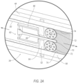
Figure 2A is a close-up of a portion of the cross-section view ofFigure 2 . -
Figure 3 is a cross section view of the syringe pump. -
Figure 4 is a schematic of components of the hydraulic suspension system. -
Figure 5 is a block diagram of components of the vehicle. - A hydraulic suspension system for use in a vehicle to control movement of wheels relative to a body includes at least two hydraulic damper assemblies. The suspension system includes a syringe pump in fluid communication with the hydraulic damper assemblies. The syringe pump includes a barrel having an opening. The syringe pump includes a plunger slidable within the barrel in a first direction that moves hydraulic fluid into the barrel via the opening. The plunger is slidable in a second direction that moves hydraulic out of the barrel via the opening. The hydraulic suspension system includes an actuator supported within the barrel and operatively coupled to the plunger.
- The syringe pump of the hydraulic suspension system provides increased packaging and cost efficiencies, e.g., requires less components than conventional hydraulic suspension systems. As one example, the syringe pump replaces and eliminates the necessity for the hydraulic suspension system to include a conventional reservoir tank and reciprocating or vibration pump connected thereto.
- With reference to
Figure 1 , where like reference numbers indicate like elements throughout the several views, anexemplary vehicle 20 is shown. - The
vehicle 20 may be any suitable type of ground vehicle, e.g., a passenger or commercial automobile such as a sedan, a coupe, a truck, a sport utility, a crossover, a van, a minivan, a taxi, a bus, etc. - In the present application, relative vehicular orientations and directions by way of example, top, bottom, front, rear, outboard, inboard, inward, outward, lateral, left, right, etc. is from the perspective of an occupant seated in the
vehicle 20 facing forward, e.g., toward a forward instrument panel and/or forward windshield of thevehicle 20. The forward direction of thevehicle 20 is the direction of movement of thevehicle 20 when thevehicle 20 is engaged in forward drive withwheels 34 of thevehicle 20 straight. Orientations and directions relative to the assembly are given related to when the assembly is supported by thevehicle 20 as described below and shown in the Figures. - The
vehicle 20 defines a longitudinal axis A1, e.g., extending between afront end 22 and arear end 24 of thevehicle 20. Thevehicle 20 defines a lateral axis A2, e.g., extending between aleft side 26 and aright side 28 of thevehicle 20. Thevehicle 20 defines a vertical axis A3, e.g., extending between a top and a bottom of thevehicle 20. The longitudinal axis A1, the lateral axis A2, and the vertical axis A3 are perpendicular to each other. - The
vehicle 20 includes a vehicle frame. The vehicle frame may be of a unibody construction in which the frame is unitary with avehicle body 30, e.g., including frame rails, pillars, roof rails, etc. As another example, thebody 30 and frame may have a body-on-frame construction also referred to as a cab-on-frame construction in which thebody 30 and frame are separate components, i.e., are modular, and thebody 30 is supported on and affixed to the frame. Alternatively, the frame andbody 30 may have any suitable construction. The frame andbody 30 may be of any suitable material, for example, steel, aluminum, and/or fiber-reinforced plastic, etc. - The
vehicle 20 includes asuspension system 32 that controls vertical movement of thewheels 34 of thevehicle 20 relative to thebody 30 of thevehicle 20, e.g., to absorb impact of bumps, potholes and other elevation changes of a road surface encountered by thevehicle 20, to adjust a ride height of thevehicle 20, to limit sway (e.g., lateral roll) of thebody 30, etc. Thesuspension system 32 may includedamper assemblies 36, springs, etc. Thedamper assemblies 36 are typically used in conjunction with the other components of thesuspension system 32 to control movement of thewheels 34 of thevehicle 20 relative to thebody 30 of thevehicle 20. In order to control movement,damper assemblies 36 are operatively connected between thebody 30 and thewheels 34 thevehicle 20. Thevehicle 20 may include, for example, aseparate damper assembly 36 at eachwheel 34. Eachdamper assembly 36 may be coupled with a coil spring. - The damper assemblies 36 control movement of
respective wheels 34 of thevehicle 20 by limiting flow of hydraulic fluid into, out of, and/or between various chambers of thedamper assembly 36, e.g., into, out of, and/or between a compression chamber and a rebound chamber. Fluid movement is caused by movement of a piston within a pressure tube of thedamper assembly 36, e.g., when thedamper assembly 36 is moved toward the compressed position or the extended position. - The
vehicle 20, e.g., thesuspension system 32, may be free from having an anti-sway bar connecting thebody 30 and one of thewheels 34 at theright side 28 and one of thewheels 34 atleft side 26. Thesuspension system 32 may compensate for the lack of the anti-sway bar via selectively controlling hydraulic fluid flow to thedamper assemblies 36, e.g., as described below. - The
suspension system 32 includes asyringe pump 38 that provides pressure to hydraulic fluid used with thedamper assemblies 36. Thesyringe pump 38 is in fluid communication with thedamper assemblies 36 such that hydraulic fluid may flow from thesyringe pump 38 to thedamper assemblies 36. For example, a plurality ofhydraulic lines 40 may connect thesyringe pump 38 to thedamper assemblies 36. - The
syringe pump 38 stores reserve hydraulic fluid, e.g., in apressure chamber 42 of thesyringe pump 38. Fluid from thesyringe pump 38 may be provided to thedamper assemblies 36, e.g., without drawing such fluid from a reservoir tank. In other words, thesuspension system 32 may be free from having a reservoir tank in fluid communication with thesyringe pump 38. - The
syringe pump 38 may be elongated along the lateral axis A2, i.e., thesyringe pump 38 may be longer along the lateral axis A2 than along the longitudinal axis A1 and the vertical axis A3. Thesyringe pump 38 may be cylindrical. Thesyringe pump 38 may be supported by, e.g., fixed to, thebody 30. Thesyringe pump 38 may be supported at thefront end 22 of thebody 30, e.g., at a volume typically occupied by an anti-sway bar. - The
syringe pump 38 can include abarrel 44 that defines thepressure chamber 42. Thebarrel 44 can store and pressurize hydraulic fluid in thepressure chamber 42. Thebarrel 44 may be elongated along the lateral axis A2. For example, thebarrel 44 may be a hollow tube surrounding thepressure chamber 42. Thebarrel 44 may includeopposing ends 46 spaced from each other along a pump axis A4. The pump axis A4 may be parallel to the lateral axis A2. Theends 46 may be closed. Thebarrel 44 may include anopening 48 that enables fluid flow into or out of thepressure chamber 42. The opening 48 may be, for example, at one of theends 46. The opening 48 may be coupled to one of thehydraulic lines 40, e.g., such that fluid may flow into and out of thepressure chamber 42 to and from thehydraulic line 40 via theopening 48. - The
syringe pump 38 can include aninner barrel 50. Theinner barrel 50 may be, for example, a hollow tube. Theinner barrel 50 may be supported by within thebarrel 44. Theinner barrel 50 may be fixed to thebarrel 44, e.g., to one of theends 46 of thebarrel 44. Thebarrel 44 and theinner barrel 50 may be concentric on the pump axis A4. Theinner barrel 50 may be elongated along the lateral axis A2. Theinner barrel 50 may include asecond end 52, e.g., enclosing the hollow tube. Thesecond end 52 may include asecond opening 54. - The
syringe pump 38 includes aplunger 56 slidable within thebarrel 44. Movement of theplunger 56 varies volume of thepressure chamber 42. With reference toFigure 2 , movement of theplunger 56 within thebarrel 44 in a first direction D1 increases the volume of thepressure chamber 42 and may move hydraulic fluid into thebarrel 44 via theopening 48, e.g., from thehydraulic line 40. Movement of theplunger 56 in the first direction D1 decreases pressure in thepressure chamber 42. The first direction D1 may be away from theopening 48. With reference toFigure 3 , movement of theplunger 56 in a second direction D2 decreases the volume and moves hydraulic fluid of thebarrel 44 via theopening 48, e.g., into thehydraulic line 40. Movement of theplunger 56 in the second direction D2 may increase pressure in thepressure chamber 42. The second direction D2 is opposite the first direction D1. For example, the second direction D2 may be toward from theopening 48. - The
plunger 56 may be, for example, a hollow tube. Theplunger 56 may include anopen end 58 and aclosed end 60 spaced from each other along the pump axis A4. Theplunger 56 may be elongated along the lateral axis A2. Thepressure chamber 42 may be between theclosed end 60 of theplunger 56 and theend 46 of thebarrel 44 having theopening 48. Theplunger 56 may be supported between theinner barrel 50 and thebarrel 44. For example, theplunger 56 may define an outer diameter that is smaller than an inner diameter of thebarrel 44 and an inner diameter that is larger than an outer diameter of theinner barrel 50. Theplunger 56 may be concentric with thebarrel 44 and theinner barrel 50 on the pump axis A4. Theinner barrel 50 may extend from within theplunger 56 to outside theplunger 56, e.g., through theopen end 58. - The
syringe pump 38 may include anactuator 62 operatively coupled to theplunger 56, i.e., such that actuation ofactuator 62 moves theplunger 56 in the first direction D1 or the second direction D2. Theactuator 62 may actuate to move theplunger 56 in the first direction D1 or the second direction D2 in response to receiving a command from acomputer 64. The command may specify the first direction D1 or the second direction D2. - With reference to
Figure 2A , theactuator 62 may include amotor 66 or other suitable electro-mechanical structure coupled to theplunger 56. Rotation of adriveshaft 68 of themotor 66 in one direction may move theplunger 56 in the first direction D1 and rotation of thedriveshaft 68 in an opposite direction may move theplunger 56 in the second direction D2. For example, aworm 70 may be operatively coupled to themotor 66 such that rotation of thedriveshaft 68 rotates theworm 70. Theworm 70 may include a spiral thread. Theworm 70 may be fixed to thedriveshaft 68. One or more worm gears 72 may be engaged with theworm 70, i.e., such that rotation of theworm 70 rotates the worm gears 72. For example, the worm gears 72 may include teeth meshed with the spiral thread of theworm 70. The worm gears 72 may be engaged with one ormore racks 74 fixed to theplunger 56, e.g., the teeth of the worm gears 72 may be meshed with teeth of theracks 74. Rotation of the worm gears 72 moves theracks 74 and theplunger 56 linearly in the first direction D1 or the second direction D2. Therack 74 may be at an inner surface of theplunger 56. Theracks 74 and theplunger 56 may be unitary. Unitary means a single, uniform piece of material with no seams, joints, fasteners, or adhesives holding it together, i.e., formed together simultaneously as a single continuous unit, e.g., by machining from a unitary blank, molding, forging, casting, etc. Non-unitary components, in contrast, are formed separately and subsequently assembled, e.g., by threaded engagement, welding, etc. - The
actuator 62 may be supported within thebarrel 44, e.g., within theplunger 56 and/or theinner barrel 50. For example, themotor 66 may be fixed within theinner barrel 50 and at thesecond end 52. Themotor 66 may be concentric with thebarrel 44, theinner barrel 50, and/or theplunger 56. Thedriveshaft 68 may extend out of theinner barrel 50, e.g., through thesecond opening 54 of thesecond end 52 of theinner barrel 50. Theworm 70 and worm gears 72 may be within theplunger 56. Thesecond end 52 of theinner barrel 50 may be between themotor 66 and theworm 70 and the worm gears 72 along the pump axis A4. Theclosed end 60 of theplunger 56 may be between thepressure chamber 42 and theworm 70 and the worm gears 72 along the pump axis A4. - With reference to
Figures 1 and4 , thesuspension system 32 may include a manifold 76. The manifold 76 is fluidly connected between thesyringe pump 38 and thedamper assemblies 36, e.g., via thehydraulic lines 40. The manifold 76 selectively provides hydraulic fluid from thesyringe pump 38 to thevarious damper assemblies 36. For example, the manifold 76 may provide hydraulic fluid from thesyringe pump 38 to one or more of thedamper assemblies 36 and not to others. The manifold 76 may include apump port 78 connected to thesyringe pump 38, e.g., via one of thehydraulic lines 40. The manifold 76 may include a plurality ofdamper ports 80, each connected to a respective one of thedamper assemblies 36, e.g., via thehydraulic lines 40. Thepump port 78 is in fluid communication with thedamper ports 80, i.e., such that hydraulic fluid can flow therebetween. - The manifold 76 may include one or
more valves 82. Thevalves 82 control fluid flow from thesyringe pump 38 to thedamper assemblies 36. Eachvalve 82 moves between an open position that permits fluid flow and a closed position that inhibits fluid flow. One of thevalves 82 may be at each ofdamper ports 80, e.g., permitting or inhibiting fluid flow between thesyringe pump 38 and therespective damper assemblies 36. Thevalve 82 may include solenoids and/or other suitable structure, e.g., as conventionally known, for moving therespective valve 82 from the closed position to the open position, or vice versa. Thevalves 82 may move from the closed position to the open position, or vice versa, in response to a command from thecomputer 64. - With reference to
Figure 5 , thecomputer 64 includes a processor and a memory. The memory includes one or more forms of computer readable media, and stores instructions executable by thecomputer 64 for performing various operations, including as disclosed herein. For example, thecomputer 64 can be ageneric computer 64 with a processor and memory as described above and/or may include an electronic control unit ECU or controller for a specific function or set of functions, and/or a dedicated electronic circuit including an ASIC that is manufactured for a particular operation, e.g., an ASIC for processing sensor data and/or communicating the sensor data. In another example,computer 64 may include an FPGA (Field-Programmable Gate Array) which is an integrated circuit manufactured to be configurable by a user. Typically, a hardware description language such as VHDL (Very High Speed Integrated Circuit Hardware Description Language) is used in electronic design automation to describe digital and mixed-signal systems such as FPGA and ASIC. For example, an ASIC is manufactured based on VHDL programming provided pre-manufacturing, whereas logical components inside an FPGA may be configured based on VHDL programming, e.g., stored in a memory electrically connected to the FPGA circuit. In some examples, a combination of processor(s), ASIC(s), and/or FPGA circuits may be included in thecomputer 64. The memory can be of any type, e.g., hard disk drives, solid state drives, servers, or any volatile or non-volatile media. The memory can store the collected data sent from sensors. The memory can be a separate device from thecomputer 64, and thecomputer 64 can retrieve information stored by the memory via a network in thevehicle 20, e.g., over a CAN bus, a wireless network, etc. Alternatively or additionally, the memory can be part of thecomputer 64, e.g., as a memory of thecomputer 64. - The
computer 64 is generally arranged for communications on avehicle communication network 84 that can include a bus in thevehicle 20 such as a controller area network CAN or the like, and/or other wired and/or wireless mechanisms. Thecomputer 64 may be in electrical communication with thesyringe pump 38 and the manifold 76 via thecommunication network 84. Alternatively or additionally, in cases where thecomputer 64 actually comprises a plurality of devices, thevehicle communication network 84 may be used for communications between devices represented as thecomputer 64 in this disclosure. Further, various controllers and/or sensors may provide data to thecomputer 64 via thevehicle communication network 84. - The
computer 64 may be programmed to, i.e., the memory includes instructions executable by the processor to, to decrease hydraulic pressure in one or more of thehydraulic damper assemblies 36, e.g., by commanding theactuator 62 of thesyringe pump 38 to move theplunger 56 in the first direction D1. Thecomputer 64 can increase hydraulic pressure in thehydraulic damper assemblies 36, e.g., by commanding the actuator 62 to move theplunger 56 in the second direction D2. Thecomputer 64 may command theactuator 62, for example, by providing a specified voltage to themotor 66. The voltage may cause rotation of thedriveshaft 68 in one direction or the other, e.g., depending on a polarity of the voltage. - The
computer 64 may be programmed to selectively command thevalves 82 to the open position and the closed position. For example, thecomputer 64 may send one or more commands via the communication network specifying which valves 82 (if any) should be open and which valves 82 (if any) should be closed. - The
computer 64 may be programmed to command theactuator 62 and the manifold 76 to individually increase or decrease hydraulic pressure at one or more specifichydraulic damper assemblies 36 of thehydraulic damper assemblies 36. For example, thecomputer 64 may first openvalves 82 connected todamper assemblies 36 at theright side 28 of thevehicle 20 and close valves andvalves 82 connected todamper assemblies 36 at theleft side 26 of thevehicle 20. Thecomputer 64 may then command theactuator 62 to increase or decrease hydraulic pressure provided by thesyringe pump 38, thereby increasing or decreasing hydraulic pressure provided to thedamper assemblies 36 at theright side 28 connected via theopen valves 82. Increasing pressure provided at the right side 28 (relative to the left side 26) may reduce roll of thebody 30, e.g., when executing a left turn and compensating for thevehicle 20 being free from having an anti-sway bar. - Computer executable instructions may be compiled or interpreted from computer programs created using a variety of programming languages and/or technologies, including, without limitation, and either alone or in combination, Java , C, C , Visual Basic, Java Script, Perl, HTML, etc. In general, a processor e.g., a microprocessor receives instructions, e.g., from a memory, a computer readable medium, etc., and executes these instructions, thereby performing one or more processes, including one or more of the processes described herein. Such instructions and other data may be stored and transmitted using a variety of computer readable media. A file in a networked device is generally a collection of data stored on a computer readable medium, such as a storage medium, a random access memory, etc. A computer readable medium includes any medium that participates in providing data e.g., instructions, which may be read by a computer. Such a medium may take many forms, including, but not limited to, non-volatile media and volatile media. Instructions may be transmitted by one or more transmission media, including fiber optics, wires, wireless communication, including the internals that comprise a system bus coupled to a processor of a computer. Common forms of computer-readable media include, for example, RAM, a PROM, an EPROM, a FLASH-EEPROM, any other memory chip or cartridge, or any other medium from which a computer can read.
- The term "exemplary" is used herein in the sense of signifying an example, e.g., a reference to an "exemplary widget" should be read as simply referring to an example of a widget.
- Use of in response to and upon determining indicates a causal relationship, not merely a temporal relationship.
- The disclosure has been described in an illustrative manner, and it is to be understood that the terminology which has been used is intended to be in the nature of words of description rather than of limitation. Many modifications and variations of the present disclosure are possible in light of the above teachings, and the disclosure may be practiced otherwise than as specifically described.
Claims (15)
- A system for use in a vehicle, the system comprising:at least two hydraulic damper assemblies;a syringe pump in fluid communication with the hydraulic damper assemblies, the syringe pump including a barrel having an opening, and including a plunger slidable within the barrel in a first direction that moves hydraulic fluid into the barrel via the opening and in a second direction that moves hydraulic out of the barrel via the opening; andan actuator supported within the barrel and operatively coupled to the plunger.
- The system of claim 1, further comprising a manifold fluidly connected between the syringe pump and the hydraulic damper assemblies.
- The system of claim 1, wherein the actuator includes a motor concentric with the barrel.
- The system of claim 1, wherein the plunger is hollow, and the actuator is supported within the plunger.
- The system of claim 1, wherein the syringe pump includes an inner barrel, the plunger supported between the inner barrel and the barrel.
- The system of claim 5, wherein the actuator includes a motor supported within the inner barrel and a driveshaft that extends out of the inner barrel.
- The system of claim 5, wherein the barrel, the plunger, and the inner barrel are elongated along an axis, and the barrel, the plunger, and the inner barrel are concentric on the axis.
- The system of any of claims 1-7, wherein the actuator includes a worm operatively coupled to a motor and a worm gear engaged with the worm, and wherein the plunger includes a rack engaged with the worm gear.
- A vehicle, comprising:a body;a wheel;a hydraulic damper assembly operatively connected between the body and the wheel;a syringe pump in fluid communication with the hydraulic damper assembly, the syringe pump including a barrel having an opening and elongated along a vehicle-lateral axis, and having a plunger slidable within the barrel in a first direction that moves hydraulic fluid into the barrel via the opening and in a second direction that moves hydraulic out of the barrel via the opening; andan actuator operatively coupled to the plunger.
- The vehicle of claim 9, wherein the body includes a front end, and the syringe pump is supported at the front end.
- The vehicle of claim 9, wherein the syringe pump includes an inner barrel, the plunger supported between the inner barrel and the barrel.
- The vehicle of claim 9, wherein the actuator includes a worm operatively coupled to a motor and a worm gear engaged with the worm, and the plunger includes a rack engaged with the worm gear.
- The vehicle of any of claims 9-12, further comprising a second wheel and a second hydraulic damper assembly in fluid communication with the syringe pump and operatively connected between the body and the second wheel, and further comprising a manifold fluidly connected between the syringe pump and the hydraulic damper assembly and the second hydraulic damper assembly, the manifold including at least one valve that controls fluid flow from the syringe pump to the hydraulic damper assembly and the second hydraulic damper assembly.
- The vehicle of claim 13, further comprising a computer programmed to command the actuator and the manifold to individually increase or decrease hydraulic pressure at the hydraulic damper assembly and the second hydraulic damper assembly.
- The vehicle of claim 13, wherein the wheel is at a right side of the body and the second wheel is at a left side of the body, and wherein the vehicle is free from having an anti-sway bar connecting the body and the wheel and the second wheel
Applications Claiming Priority (1)
| Application Number | Priority Date | Filing Date | Title |
|---|---|---|---|
| US17/405,250 US20230055142A1 (en) | 2021-08-18 | 2021-08-18 | Damper assembly and syringe pump |
Publications (1)
| Publication Number | Publication Date |
|---|---|
| EP4137336A1 true EP4137336A1 (en) | 2023-02-22 |
Family
ID=82786295
Family Applications (1)
| Application Number | Title | Priority Date | Filing Date |
|---|---|---|---|
| EP22188478.6A Withdrawn EP4137336A1 (en) | 2021-08-18 | 2022-08-03 | Damper assembly and syringe pump |
Country Status (3)
| Country | Link |
|---|---|
| US (1) | US20230055142A1 (en) |
| EP (1) | EP4137336A1 (en) |
| CN (1) | CN115707881A (en) |
Citations (3)
| Publication number | Priority date | Publication date | Assignee | Title |
|---|---|---|---|---|
| WO2011081522A2 (en) * | 2009-12-29 | 2011-07-07 | Daf Trucks N.V. | Hydraulic steering system for use in transport vehicles |
| US10458398B2 (en) * | 2015-07-08 | 2019-10-29 | Mando Corporation | Method of setting zero point of bi-directional linear pump for active suspension apparatus |
| JP6738510B1 (en) * | 2020-03-23 | 2020-08-12 | 株式会社ショーワ | Fluid supply device, height adjustment device, saddle type vehicle |
Family Cites Families (18)
| Publication number | Priority date | Publication date | Assignee | Title |
|---|---|---|---|---|
| US2650107A (en) * | 1950-01-16 | 1953-08-25 | George O Monnig | Stabilizing device for vehicles and other purposes |
| US2651385A (en) * | 1950-04-18 | 1953-09-08 | United Aircraft Prod | Shimmy dampener |
| US2887324A (en) * | 1955-09-28 | 1959-05-19 | Gen Motors Corp | Fluid suspension control mechanism |
| DE1154358B (en) * | 1956-10-16 | 1963-09-12 | Daimler Benz Ag | Compensation device for the wheel suspensions of vehicles, especially motor vehicles |
| NL301357A (en) * | 1962-12-05 | 1900-01-01 | ||
| US3444784A (en) * | 1966-12-19 | 1969-05-20 | Robert L Wengerd | Fluid motor rotary actuator |
| US3501088A (en) * | 1968-07-22 | 1970-03-17 | Anton Braun | Balanced free piston engine |
| DE19916366A1 (en) * | 1999-04-13 | 2000-10-19 | Zahnradfabrik Friedrichshafen | Actuator |
| DE20209120U1 (en) * | 2002-06-12 | 2003-10-16 | Hemscheidt Fahrwerktechnik GmbH & Co., 42781 Haan | Suspension device for motor vehicles |
| EP1862338A1 (en) * | 2006-05-29 | 2007-12-05 | Nederlandse Organisatie voor Toegepast-Natuuurwetenschappelijk Onderzoek TNO | Suspension system for a vehicle |
| DE102007028634A1 (en) * | 2007-06-21 | 2009-01-02 | Zf Friedrichshafen Ag | Piston-cylinder assembly |
| JP6012356B2 (en) * | 2012-09-18 | 2016-10-25 | 株式会社ショーワ | Height adjustment device for motorcycles |
| JP6012449B2 (en) * | 2012-12-14 | 2016-10-25 | 株式会社ショーワ | Height adjustment device for motorcycles |
| WO2015073811A1 (en) * | 2013-11-15 | 2015-05-21 | Firestone Industrial Products Company, Llc | End closures as well as gas spring assemblies and methods of assembly including same |
| KR102032450B1 (en) * | 2014-10-22 | 2019-10-21 | 주식회사 만도 | Active suspension apparatus for vehicle |
| US10272891B2 (en) * | 2016-07-28 | 2019-04-30 | Kelsey-Hayes Company | Compliant torque coupler for a dual acting plunger assembly of a vehicle brake system |
| CA3035661A1 (en) * | 2018-03-05 | 2019-09-05 | Thunder Heart Performance Corp. | Motorcycle suspension system with integrated ride height sensor |
| KR20200028156A (en) * | 2018-09-06 | 2020-03-16 | 주식회사 만도 | Energy active regeneration device for suspension |
-
2021
- 2021-08-18 US US17/405,250 patent/US20230055142A1/en not_active Abandoned
-
2022
- 2022-08-01 CN CN202210914205.5A patent/CN115707881A/en active Pending
- 2022-08-03 EP EP22188478.6A patent/EP4137336A1/en not_active Withdrawn
Patent Citations (3)
| Publication number | Priority date | Publication date | Assignee | Title |
|---|---|---|---|---|
| WO2011081522A2 (en) * | 2009-12-29 | 2011-07-07 | Daf Trucks N.V. | Hydraulic steering system for use in transport vehicles |
| US10458398B2 (en) * | 2015-07-08 | 2019-10-29 | Mando Corporation | Method of setting zero point of bi-directional linear pump for active suspension apparatus |
| JP6738510B1 (en) * | 2020-03-23 | 2020-08-12 | 株式会社ショーワ | Fluid supply device, height adjustment device, saddle type vehicle |
Also Published As
| Publication number | Publication date |
|---|---|
| CN115707881A (en) | 2023-02-21 |
| US20230055142A1 (en) | 2023-02-23 |
Similar Documents
| Publication | Publication Date | Title |
|---|---|---|
| US11904841B2 (en) | Suspension system integration with advanced driver assistance system | |
| US11926368B2 (en) | Cab suspension systems and associated methods of manufacture and use | |
| US11865887B2 (en) | Suspension system with incremental roll and pitch stiffness control | |
| US12059937B2 (en) | Suspension system with roll and pitch stiffness deactivation based on road profile information | |
| CN105584309B (en) | Couple torsion beam type axle suspension system | |
| EP2804774B1 (en) | Driver's cab suspension device with roll stabilizing means | |
| US10017023B2 (en) | Method for controlling the level of an air-suspended motor vehicle | |
| US11511592B2 (en) | Suspension system for a vehicle | |
| DE102013102588B4 (en) | Vehicle height adjustment device for a motorcycle | |
| CN115451057B (en) | Shock absorber assemblies, vehicles, and vehicle damping control methods | |
| JP4894545B2 (en) | Vehicle suspension system | |
| WO2006056374A2 (en) | Process for controlling and regulating an active chassis system | |
| CN107662467A (en) | Vehicle suspension system | |
| US12441153B2 (en) | Vehicle damper extension | |
| AU2010238552A8 (en) | Towing tractor | |
| US20230055142A1 (en) | Damper assembly and syringe pump | |
| EP4717477A1 (en) | Suspension system | |
| EP1795386A1 (en) | Active vehicle suspension for motor vehicle | |
| DE10352186B4 (en) | Vehicle, in particular motor vehicle | |
| JP7836166B2 (en) | Suspension system | |
| EP2532539A1 (en) | Method for regulating the impact absorption for an axle of a suspension for a motor vehicle | |
| CN101061002B (en) | Spring-damper device for motor vehicles, and level-regulating system for motor vehicles | |
| DE19646873A1 (en) | Hydraulically operated progressive torsion bar suspension for vehicle | |
| JP3062617B2 (en) | Suspension device | |
| Li | Development of height adjustment system for vehicle slow attitude control |
Legal Events
| Date | Code | Title | Description |
|---|---|---|---|
| PUAI | Public reference made under article 153(3) epc to a published international application that has entered the european phase |
Free format text: ORIGINAL CODE: 0009012 |
|
| STAA | Information on the status of an ep patent application or granted ep patent |
Free format text: STATUS: REQUEST FOR EXAMINATION WAS MADE |
|
| 17P | Request for examination filed |
Effective date: 20220803 |
|
| AK | Designated contracting states |
Kind code of ref document: A1 Designated state(s): AL AT BE BG CH CY CZ DE DK EE ES FI FR GB GR HR HU IE IS IT LI LT LU LV MC MK MT NL NO PL PT RO RS SE SI SK SM TR |
|
| P01 | Opt-out of the competence of the unified patent court (upc) registered |
Effective date: 20230528 |
|
| STAA | Information on the status of an ep patent application or granted ep patent |
Free format text: STATUS: THE APPLICATION IS DEEMED TO BE WITHDRAWN |
|
| 18D | Application deemed to be withdrawn |
Effective date: 20250301 |