EP4137290A1 - Core and method for molding structure - Google Patents
Core and method for molding structure Download PDFInfo
- Publication number
- EP4137290A1 EP4137290A1 EP21788852.8A EP21788852A EP4137290A1 EP 4137290 A1 EP4137290 A1 EP 4137290A1 EP 21788852 A EP21788852 A EP 21788852A EP 4137290 A1 EP4137290 A1 EP 4137290A1
- Authority
- EP
- European Patent Office
- Prior art keywords
- die
- skin
- stringer
- core
- longitudinal direction
- Prior art date
- Legal status (The legal status is an assumption and is not a legal conclusion. Google has not performed a legal analysis and makes no representation as to the accuracy of the status listed.)
- Granted
Links
Images


Classifications
-
- B—PERFORMING OPERATIONS; TRANSPORTING
- B29—WORKING OF PLASTICS; WORKING OF SUBSTANCES IN A PLASTIC STATE IN GENERAL
- B29D—PRODUCING PARTICULAR ARTICLES FROM PLASTICS OR FROM SUBSTANCES IN A PLASTIC STATE
- B29D99/00—Subject matter not provided for in other groups of this subclass
- B29D99/001—Producing wall or panel-like structures, e.g. for hulls, fuselages, or buildings
- B29D99/0014—Producing wall or panel-like structures, e.g. for hulls, fuselages, or buildings provided with ridges or ribs, e.g. joined ribs
-
- B—PERFORMING OPERATIONS; TRANSPORTING
- B29—WORKING OF PLASTICS; WORKING OF SUBSTANCES IN A PLASTIC STATE IN GENERAL
- B29C—SHAPING OR JOINING OF PLASTICS; SHAPING OF MATERIAL IN A PLASTIC STATE, NOT OTHERWISE PROVIDED FOR; AFTER-TREATMENT OF THE SHAPED PRODUCTS, e.g. REPAIRING
- B29C70/00—Shaping composites, i.e. plastics material comprising reinforcements, fillers or preformed parts, e.g. inserts
- B29C70/04—Shaping composites, i.e. plastics material comprising reinforcements, fillers or preformed parts, e.g. inserts comprising reinforcements only, e.g. self-reinforcing plastics
- B29C70/28—Shaping operations therefor
- B29C70/30—Shaping by lay-up, i.e. applying fibres, tape or broadsheet on a mould, former or core; Shaping by spray-up, i.e. spraying of fibres on a mould, former or core
-
- B—PERFORMING OPERATIONS; TRANSPORTING
- B29—WORKING OF PLASTICS; WORKING OF SUBSTANCES IN A PLASTIC STATE IN GENERAL
- B29C—SHAPING OR JOINING OF PLASTICS; SHAPING OF MATERIAL IN A PLASTIC STATE, NOT OTHERWISE PROVIDED FOR; AFTER-TREATMENT OF THE SHAPED PRODUCTS, e.g. REPAIRING
- B29C33/00—Moulds or cores; Details thereof or accessories therefor
- B29C33/38—Moulds or cores; Details thereof or accessories therefor characterised by the material or the manufacturing process
-
- B—PERFORMING OPERATIONS; TRANSPORTING
- B29—WORKING OF PLASTICS; WORKING OF SUBSTANCES IN A PLASTIC STATE IN GENERAL
- B29C—SHAPING OR JOINING OF PLASTICS; SHAPING OF MATERIAL IN A PLASTIC STATE, NOT OTHERWISE PROVIDED FOR; AFTER-TREATMENT OF THE SHAPED PRODUCTS, e.g. REPAIRING
- B29C33/00—Moulds or cores; Details thereof or accessories therefor
- B29C33/76—Cores
-
- B—PERFORMING OPERATIONS; TRANSPORTING
- B29—WORKING OF PLASTICS; WORKING OF SUBSTANCES IN A PLASTIC STATE IN GENERAL
- B29C—SHAPING OR JOINING OF PLASTICS; SHAPING OF MATERIAL IN A PLASTIC STATE, NOT OTHERWISE PROVIDED FOR; AFTER-TREATMENT OF THE SHAPED PRODUCTS, e.g. REPAIRING
- B29C70/00—Shaping composites, i.e. plastics material comprising reinforcements, fillers or preformed parts, e.g. inserts
- B29C70/04—Shaping composites, i.e. plastics material comprising reinforcements, fillers or preformed parts, e.g. inserts comprising reinforcements only, e.g. self-reinforcing plastics
- B29C70/28—Shaping operations therefor
- B29C70/40—Shaping or impregnating by compression not applied
- B29C70/42—Shaping or impregnating by compression not applied for producing articles of definite length, i.e. discrete articles
- B29C70/44—Shaping or impregnating by compression not applied for producing articles of definite length, i.e. discrete articles using isostatic pressure, e.g. pressure difference-moulding, vacuum bag-moulding, autoclave-moulding or expanding rubber-moulding
- B29C70/446—Moulding structures having an axis of symmetry or at least one channel, e.g. tubular structures, frames
-
- B—PERFORMING OPERATIONS; TRANSPORTING
- B29—WORKING OF PLASTICS; WORKING OF SUBSTANCES IN A PLASTIC STATE IN GENERAL
- B29C—SHAPING OR JOINING OF PLASTICS; SHAPING OF MATERIAL IN A PLASTIC STATE, NOT OTHERWISE PROVIDED FOR; AFTER-TREATMENT OF THE SHAPED PRODUCTS, e.g. REPAIRING
- B29C70/00—Shaping composites, i.e. plastics material comprising reinforcements, fillers or preformed parts, e.g. inserts
- B29C70/04—Shaping composites, i.e. plastics material comprising reinforcements, fillers or preformed parts, e.g. inserts comprising reinforcements only, e.g. self-reinforcing plastics
- B29C70/28—Shaping operations therefor
- B29C70/40—Shaping or impregnating by compression not applied
- B29C70/42—Shaping or impregnating by compression not applied for producing articles of definite length, i.e. discrete articles
- B29C70/46—Shaping or impregnating by compression not applied for producing articles of definite length, i.e. discrete articles using matched moulds, e.g. for deforming sheet moulding compounds [SMC] or prepregs
- B29C70/462—Moulding structures having an axis of symmetry or at least one channel, e.g. tubular structures, frames
-
- B—PERFORMING OPERATIONS; TRANSPORTING
- B29—WORKING OF PLASTICS; WORKING OF SUBSTANCES IN A PLASTIC STATE IN GENERAL
- B29C—SHAPING OR JOINING OF PLASTICS; SHAPING OF MATERIAL IN A PLASTIC STATE, NOT OTHERWISE PROVIDED FOR; AFTER-TREATMENT OF THE SHAPED PRODUCTS, e.g. REPAIRING
- B29C70/00—Shaping composites, i.e. plastics material comprising reinforcements, fillers or preformed parts, e.g. inserts
- B29C70/04—Shaping composites, i.e. plastics material comprising reinforcements, fillers or preformed parts, e.g. inserts comprising reinforcements only, e.g. self-reinforcing plastics
- B29C70/28—Shaping operations therefor
- B29C70/54—Component parts, details or accessories; Auxiliary operations, e.g. feeding or storage of prepregs or SMC after impregnation or during ageing
-
- B—PERFORMING OPERATIONS; TRANSPORTING
- B29—WORKING OF PLASTICS; WORKING OF SUBSTANCES IN A PLASTIC STATE IN GENERAL
- B29C—SHAPING OR JOINING OF PLASTICS; SHAPING OF MATERIAL IN A PLASTIC STATE, NOT OTHERWISE PROVIDED FOR; AFTER-TREATMENT OF THE SHAPED PRODUCTS, e.g. REPAIRING
- B29C33/00—Moulds or cores; Details thereof or accessories therefor
- B29C33/44—Moulds or cores; Details thereof or accessories therefor with means for, or specially constructed to facilitate, the removal of articles, e.g. of undercut articles
- B29C33/48—Moulds or cores; Details thereof or accessories therefor with means for, or specially constructed to facilitate, the removal of articles, e.g. of undercut articles with means for collapsing or disassembling
- B29C33/485—Moulds or cores; Details thereof or accessories therefor with means for, or specially constructed to facilitate, the removal of articles, e.g. of undercut articles with means for collapsing or disassembling cores or mandrels
-
- B—PERFORMING OPERATIONS; TRANSPORTING
- B29—WORKING OF PLASTICS; WORKING OF SUBSTANCES IN A PLASTIC STATE IN GENERAL
- B29K—INDEXING SCHEME ASSOCIATED WITH SUBCLASSES B29B, B29C OR B29D, RELATING TO MOULDING MATERIALS OR TO MATERIALS FOR MOULDS, REINFORCEMENTS, FILLERS OR PREFORMED PARTS, e.g. INSERTS
- B29K2105/00—Condition, form or state of moulded material or of the material to be shaped
- B29K2105/06—Condition, form or state of moulded material or of the material to be shaped containing reinforcements, fillers or inserts
- B29K2105/08—Condition, form or state of moulded material or of the material to be shaped containing reinforcements, fillers or inserts of continuous length, e.g. cords, rovings, mats, fabrics, strands or yarns
- B29K2105/0872—Prepregs
-
- B—PERFORMING OPERATIONS; TRANSPORTING
- B29—WORKING OF PLASTICS; WORKING OF SUBSTANCES IN A PLASTIC STATE IN GENERAL
- B29K—INDEXING SCHEME ASSOCIATED WITH SUBCLASSES B29B, B29C OR B29D, RELATING TO MOULDING MATERIALS OR TO MATERIALS FOR MOULDS, REINFORCEMENTS, FILLERS OR PREFORMED PARTS, e.g. INSERTS
- B29K2305/00—Use of metals, their alloys or their compounds, as reinforcement
- B29K2305/08—Transition metals
- B29K2305/12—Iron
-
- B—PERFORMING OPERATIONS; TRANSPORTING
- B29—WORKING OF PLASTICS; WORKING OF SUBSTANCES IN A PLASTIC STATE IN GENERAL
- B29K—INDEXING SCHEME ASSOCIATED WITH SUBCLASSES B29B, B29C OR B29D, RELATING TO MOULDING MATERIALS OR TO MATERIALS FOR MOULDS, REINFORCEMENTS, FILLERS OR PREFORMED PARTS, e.g. INSERTS
- B29K2307/00—Use of elements other than metals as reinforcement
- B29K2307/04—Carbon
-
- B—PERFORMING OPERATIONS; TRANSPORTING
- B29—WORKING OF PLASTICS; WORKING OF SUBSTANCES IN A PLASTIC STATE IN GENERAL
- B29L—INDEXING SCHEME ASSOCIATED WITH SUBCLASS B29C, RELATING TO PARTICULAR ARTICLES
- B29L2031/00—Other particular articles
- B29L2031/30—Vehicles, e.g. ships or aircraft, or body parts thereof
- B29L2031/3076—Aircrafts
- B29L2031/3082—Fuselages
-
- B—PERFORMING OPERATIONS; TRANSPORTING
- B32—LAYERED PRODUCTS
- B32B—LAYERED PRODUCTS, i.e. PRODUCTS BUILT-UP OF STRATA OF FLAT OR NON-FLAT, e.g. CELLULAR OR HONEYCOMB, FORM
- B32B2260/00—Layered product comprising an impregnated, embedded, or bonded layer wherein the layer comprises an impregnation, embedding, or binder material
- B32B2260/02—Composition of the impregnated, bonded or embedded layer
- B32B2260/021—Fibrous or filamentary layer
- B32B2260/023—Two or more layers
-
- B—PERFORMING OPERATIONS; TRANSPORTING
- B32—LAYERED PRODUCTS
- B32B—LAYERED PRODUCTS, i.e. PRODUCTS BUILT-UP OF STRATA OF FLAT OR NON-FLAT, e.g. CELLULAR OR HONEYCOMB, FORM
- B32B2260/00—Layered product comprising an impregnated, embedded, or bonded layer wherein the layer comprises an impregnation, embedding, or binder material
- B32B2260/04—Impregnation, embedding, or binder material
- B32B2260/046—Synthetic resin
-
- B—PERFORMING OPERATIONS; TRANSPORTING
- B32—LAYERED PRODUCTS
- B32B—LAYERED PRODUCTS, i.e. PRODUCTS BUILT-UP OF STRATA OF FLAT OR NON-FLAT, e.g. CELLULAR OR HONEYCOMB, FORM
- B32B2262/00—Composition or structural features of fibres which form a fibrous or filamentary layer or are present as additives
- B32B2262/10—Inorganic fibres
- B32B2262/106—Carbon fibres, e.g. graphite fibres
-
- B—PERFORMING OPERATIONS; TRANSPORTING
- B32—LAYERED PRODUCTS
- B32B—LAYERED PRODUCTS, i.e. PRODUCTS BUILT-UP OF STRATA OF FLAT OR NON-FLAT, e.g. CELLULAR OR HONEYCOMB, FORM
- B32B5/00—Layered products characterised by the non- homogeneity or physical structure, i.e. comprising a fibrous, filamentary, particulate or foam layer; Layered products characterised by having a layer differing constitutionally or physically in different parts
- B32B5/02—Layered products characterised by the non- homogeneity or physical structure, i.e. comprising a fibrous, filamentary, particulate or foam layer; Layered products characterised by having a layer differing constitutionally or physically in different parts characterised by structural features of a fibrous or filamentary layer
-
- B—PERFORMING OPERATIONS; TRANSPORTING
- B32—LAYERED PRODUCTS
- B32B—LAYERED PRODUCTS, i.e. PRODUCTS BUILT-UP OF STRATA OF FLAT OR NON-FLAT, e.g. CELLULAR OR HONEYCOMB, FORM
- B32B5/00—Layered products characterised by the non- homogeneity or physical structure, i.e. comprising a fibrous, filamentary, particulate or foam layer; Layered products characterised by having a layer differing constitutionally or physically in different parts
- B32B5/22—Layered products characterised by the non- homogeneity or physical structure, i.e. comprising a fibrous, filamentary, particulate or foam layer; Layered products characterised by having a layer differing constitutionally or physically in different parts characterised by the presence of two or more layers which are next to each other and are fibrous, filamentary, formed of particles or foamed
- B32B5/24—Layered products characterised by the non- homogeneity or physical structure, i.e. comprising a fibrous, filamentary, particulate or foam layer; Layered products characterised by having a layer differing constitutionally or physically in different parts characterised by the presence of two or more layers which are next to each other and are fibrous, filamentary, formed of particles or foamed one layer being a fibrous or filamentary layer
- B32B5/26—Layered products characterised by the non- homogeneity or physical structure, i.e. comprising a fibrous, filamentary, particulate or foam layer; Layered products characterised by having a layer differing constitutionally or physically in different parts characterised by the presence of two or more layers which are next to each other and are fibrous, filamentary, formed of particles or foamed one layer being a fibrous or filamentary layer another layer next to it also being fibrous or filamentary
-
- C—CHEMISTRY; METALLURGY
- C22—METALLURGY; FERROUS OR NON-FERROUS ALLOYS; TREATMENT OF ALLOYS OR NON-FERROUS METALS
- C22C—ALLOYS
- C22C38/00—Ferrous alloys, e.g. steel alloys
- C22C38/18—Ferrous alloys, e.g. steel alloys containing chromium
-
- Y—GENERAL TAGGING OF NEW TECHNOLOGICAL DEVELOPMENTS; GENERAL TAGGING OF CROSS-SECTIONAL TECHNOLOGIES SPANNING OVER SEVERAL SECTIONS OF THE IPC; TECHNICAL SUBJECTS COVERED BY FORMER USPC CROSS-REFERENCE ART COLLECTIONS [XRACs] AND DIGESTS
- Y02—TECHNOLOGIES OR APPLICATIONS FOR MITIGATION OR ADAPTATION AGAINST CLIMATE CHANGE
- Y02T—CLIMATE CHANGE MITIGATION TECHNOLOGIES RELATED TO TRANSPORTATION
- Y02T50/00—Aeronautics or air transport
- Y02T50/40—Weight reduction
Definitions
- the present disclosure relates to a core used in a step of forming a structural body including fiber-reinforced resin and a method of forming the structural body by using the core.
- a structural body formed by integrally molding a skin made of fiber-reinforced resin and a beam-shaped stringer has been devised.
- a stringer having a hat-shaped section that is open toward the skin can be used.
- the stringer having the hat-shaped section is advantageous in that this stringer easily follows a change in the section of the structural body and has high strength for its weight.
- a core needs to be inserted in a space between the skin and the stringer (see PTL 1, for example).
- a surface of the core which supports the skin i.e., a surface of the core which contacts the skin be not partially deformed.
- the core made of a hard material is low in flexibility, and therefore, it is not easy to pull out the core after the forming.
- the present disclosure was made under these circumstances, and an object of the present disclosure is to provide a core that is easily pulled out after forming and includes a surface which contacts a skin and is hardly partially deformed, and also provide a method of forming a structural body.
- a core according to one aspect of the present disclosure is a core that is inserted into a space between a skin and a stringer in a step of integrally molding the skin and the stringer, the skin including fiber-reinforced resin, the stringer having a hat-shaped section that is open toward the skin.
- the core includes: a first die that extends along a longitudinal direction of the stringer and contacts the skin; a second die that extends along the longitudinal direction of the stringer, is adjacent to the first die, and contacts the skin; and a third die that extends along the longitudinal direction of the stringer, is located at an opposite side of the skin across the first die and the second die, and contacts both the first die and the second die.
- the third die located at a lower side is pulled out, and therefore, the first die and the second die collapse.
- the first die and the second die are easily pulled out.
- a method of forming a structural body according to one aspect of the present disclosure includes: inserting the core into the space between the skin and the stringer; in this state, integrally molding the skin and the stringer; and then, pulling out the core from the space.
- the third die located at a lower side is pulled out, and therefore, the first die and the second die collapse.
- the first die and the second die are easily pulled out.
- the present disclosure can provide a core that is easily pulled out after forming and includes a surface which contacts a skin and is hardly partially deformed, and also provide a method of forming a structural body.
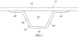
- FIG. 1 is a front view of the structural body 101 and shows a part of the structural body 101.
- the structural body 101 is an airframe of an aircraft.
- the structural body 101 includes a skin 102 and stringers 103.
- FIG. 1 shows one of the stringers 103.
- the shape of the structural body 101 is not limited and may be a flat plate shape or a cylindrical shape.
- the skin 102 is a portion corresponding to a surface of the structural body 101.
- the thickness of the skin 102 is constant.
- the skin 102 is formed in such a manner that: sheet-shaped prepregs are prepared by impregnating fibers, such as carbon, with resin; and the prepregs are laminated on each other and are cured.
- the skin 102 is made of fiber-reinforced resin.
- the thickness of the skin 102 can be adjusted by the number of prepregs laminated.
- the resin of the skin 102 of the present embodiment is thermoplastic resin but may be thermosetting resin.
- the stringer 103 is a portion which is located inside the skin 102 and formed integrally with the skin 102.
- the stringer 103 serves as a beam and extends in a predetermined direction (direction perpendicular to a paper surface of FIG. 1 ).
- the stringer 103 extends along an axial direction of the structural body 101.
- the stringer 103 of the present embodiment is made of the same material (i.e., the fiber-reinforced resin) as the skin 102.
- the stringer 103 may be made of a different material from the skin 102.
- the stringer 103 may be made of an invar alloy.
- a direction in which the stringer 103 extends is referred to as a "longitudinal direction,” and a section perpendicular to the longitudinal direction is simply referred to as a “section.”
- a direction in which the skin 102 extends in a sectional view is referred to as a "width direction,” and a direction along a perpendicular line of the skin 102 in the sectional view is referred to as a “perpendicular direction.” In some cases, the perpendicular direction does not coincide with a vertical direction.
- the stringer 103 has a hat-shaped section that is open toward the skin 102.
- the stringer 103 includes a bottom surface portion 104, two side surface portions 105, and two flange portions 106.
- the bottom surface portion 104 is located farthest from the skin 102.
- the two side surface portions 105 extend from both width direction ends of the bottom surface portion 104 toward the skin 102.
- the two flange portions 106 extend from the respective side surface portions 105 outward in the width direction while contacting the skin 102.
- the two side surface portions 105 are inclined relative to the perpendicular direction so as to extend away from each other in the width direction.
- a space 107 is between the skin 102 and the stringer 103.
- the space 107 extends in the longitudinal direction and has a trapezoidal shape in the sectional view.
- the core 100 is inserted into the space 107.
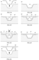
- FIGS. 2A to 2G are diagrams showing the step of forming the structural body 101.
- the below-described step of forming the structural body 101 is one example in which the skin 102 is made of thermoplastic resin.
- the skin 102 is made of thermosetting resin, a different step is performed.
- the stringer 103 is placed in a groove 109 of a base die 108 prepared in advance.
- the base die 108 has a shape corresponding to the shape of the completed structural body 101.
- the base die 108 has a plate shape or a semi-circular section.
- the core 100 is inserted into the stringer 103. Details of the core 100 will be described later.
- the skin 102 is formed along the surface of the base die 108 and the surface of the core 100. As described above, the skin 102 is formed by laminating the prepregs. At this time, the skin 102 is not yet cured and is not yet joined to the stringer 103.
- heat is applied to the skin 102, and force is applied to the surface of the skin 102 with a pressurizer 110. At this time, the force is partially applied to the skin 102. Moreover, the temperature of the skin 102 becomes a high temperature, such as 350°C. As above, when the skin 102 is pressurized while being heated, the skin 102 is cured and joined to the stringer 103. To be specific, the skin 102 and the stringer 103 are integrally molded.
- the core 100 is pulled out from the space 107 between the skin 102 and the stringer 103.
- the structural body 101 in which the skin 102 and the stringer 103 are integrated with each other is taken out from the base die 108. This is the step of forming the structural body 101.
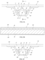
- FIG. 3A is a front view of the core 100.
- FIG. 3B is a sectional view taken along line I-I of FIG. 3A.
- FIG. 3C is a rear view of the core 100.
- FIGS. 3A to 3C show that the core 100 is in the space 107 between the skin 102 and the stringer 103. The same is true in FIGS. 4A to 4C and FIGS. 5A to 5C described later.
- the core 100 includes a first die 10, a second die 20, and a third die 30 which are separable from each other.
- the first die 10 is a die that contacts the skin 102.
- the first die 10 is located side by side with the second die 20 in the width direction and extends along the longitudinal direction.
- the first die 10 of the present embodiment has the same sectional shape regardless of the position in the longitudinal direction.
- the first die 10 of the present embodiment includes: an upper surface 11 that contacts the skin 102; an outside surface 12 that contacts the side surface portion 105 of the stringer 103; a lower surface 13 that is located at an opposite side of the upper surface 11 and contacts the third die 30; an inside surface 14 that contacts the second die 20; and a recessed surface 15 that is located between the lower surface 13 and the inside surface 14, contacts the third die 30, and has an L-shaped section.
- the second die 20 is a die that contacts the skin 102 as with the first die 10.
- the second die 20 is located side by side with the first die 10 in the width direction and extends along the longitudinal direction.
- the second die 20 of the present embodiment has the same sectional shape regardless of the position in the longitudinal direction.
- the second die 20 of the present embodiment includes: an upper surface 21 that contacts the skin 102; an outside surface 22 that contacts the side surface portion 105 of the stringer 103; a lower surface 23 that is located at an opposite side of the upper surface 21 and contacts the third die 30; an inside surface 24 that contacts the first die 10; and a recessed surface 25 that is located between the lower surface 23 and the inside surface 24, contacts the third die 30, and has an L-shaped section.
- the recessed surface 25 of the second die 20 forms an insertion groove 26 together with the recessed surface 15 of the first die 10.
- the insertion groove 26 is located at a boundary between the first die 10 and the second die 20 and extends in the longitudinal direction.
- the insertion groove 26 has a rectangular shape in the sectional view.
- the inside surface 14 of the first die 10 and the inside surface 24 of the second die 20 contact each other and are inclined relative to the perpendicular direction. Specifically, the inside surface 14 of the first die 10 is inclined such that an angle between the inside surface 14 and the upper surface 11 is an obtuse angle in the sectional view. Moreover, the inside surface 24 of the second die 20 is inclined such that an angle between the inside surface 24 and the upper surface 21 is an acute angle in the sectional view.
- the third die 30 is a die that is located at an opposite side of the skin 102 across the first die 10 and the second die 20.
- the third die 30 extends along the longitudinal direction.
- the third die 30 of the present embodiment has the same sectional shape regardless of the position in the longitudinal direction. More specifically, the third die 30 includes a main body 31 and a protrusion 32.
- the main body 31 has a rectangular shape in the sectional view.
- a lower surface 33 of the main body 31 contacts the bottom surface portion 104 of the stringer 103.
- Shoulder surfaces 34 located at both sides of the protrusion 32 of the main body 31 in the width direction contact the lower surface 13 of the first die 10 and the lower surface 23 of the second die 20.
- the main body 31 of the present embodiment has a rectangular shape in the sectional view.
- the main body 31 may have a trapezoidal shape corresponding to the sectional shape of the stringer 103.
- the protrusion 32 is a portion projecting from a width direction middle of the third die 30 toward the skin 102.
- the protrusion 32 has a rectangular shape in a sectional view and is in the insertion groove 26 formed integrally by the recessed surface 15 of the first die 10 and the recessed surface 25 of the second die 20. Therefore, the protrusion 32 contacts both the recessed surface 15 of the first die 10 and the recessed surface 25 of the second die 20.
- the dies 10, 20, and 30 of the core 100 are formed as above. Therefore, the first die 10 and the second die 20 are supported by the side surface portions 105 of the stringer 103 and the third die 30. As a result, the core 100 can withstand the force applied in the perpendicular direction through the skin 102 without collapsing as a whole.
- Both the first die 10 and the second die 20 are supported by the third die 30. If the first die 10 and the second die 20 are not supported by the third die 30, the first die 10 and the second die 20 collapse. Therefore, in the work (work in FIGS. 2E and 2F ) of pulling out the core 100 during the step of integrally molding the skin 102 and the stringer 103, the third die 30 is first pulled out, and with this, the first die 10 and the second die 20 collapse and can be easily pulled out.
- the boundary between the first die 10 and the second die 20 is inclined relative to the perpendicular direction in the sectional view. Therefore, when the third die 30 is pulled out, the first die 10 falls first, and at this time, the first die 10 and the second die 20 do not get stuck. On this account, the first die 10 and the second die 20 further easily collapse.
- the dies 10, 20, and 30 need to be made of a material that can withstand the heat applied in the step of forming the structural body 101. Moreover, it is desirable that the surfaces of the dies 10, 20, and 30 be smooth such that the friction of the dies 10, 20, and 30 with the skin 102 and the stringer 103 when the dies 10, 20, and 30 are pulled out does not become large. Based on these, the dies 10, 20, and 30 may be made of metal. Furthermore, in consideration of the manufacturing cost, the dies 10, 20, and 30 may be made of aluminum.
- FIG. 4A is a front view of the core 200.
- FIG. 4B is a sectional view taken along line II-II of FIG. 4A.
- FIG. 4C is a rear view of the core 200.
- the same reference signs are used for the same or corresponding components as the core 100 according to Embodiment 1, and the repetition of the same explanation is avoided.
- the thickness of the skin 102 is not constant but varies depending on the position in the longitudinal direction. As a result, the space 107 between the skin 102 and the stringer 103 is displaced as it extends in the longitudinal direction.
- the core 200 according to the present embodiment can be utilized for the forming of the structural body 101.
- each of the first die 10, the second die 20, and the third die 30 is divided in the longitudinal direction.
- each of the dies 10, 20, and 30 is divided into three portions in the longitudinal direction.
- the number of divided portions of each of the dies 10, 20, and 30 is not limited to this. Since each of the dies 10, 20, and 30 is divided in the longitudinal direction, the divided portions can be displaced relative to each other. As a result, the core 200 according to the present embodiment easily follows the displacement of the space 107 between the skin 102 and the stringer 103 and is easily pulled out.
- the third die 30 of the core 200 according to the present embodiment includes slits 35 perpendicular to the longitudinal direction. With this, portions of the third die 30 which are adjacent to each other across the slit 35 can be displaced relative to each other. As a result, the core 200 according to the present embodiment easily follows the displacement of the space 107 between the skin 102 and the stringer 103 and is easily pulled out.
- the number of slits 35 of the third die 30 is not limited.
- the slit 35 is open on the lower surface 33 of the third die 30 and extends from the lower surface 33 toward the skin 102.
- the slit 35 may be open on an upper surface of the third die 30 and extend toward the bottom surface portion 104 of the stringer 103.
- the third die 30 includes the slits 35.
- the first die 10 and the second die 20 may include slits.
- a dimension of the slit 35 in the perpendicular direction is not limited, and may be, for example, 50% or more of a dimension of the third die 30 in the perpendicular direction.
- FIG. 5A is a front view of the core 300.
- FIG. 5B is a sectional view taken along line III-III of FIG. 5A.
- FIG. 5C is a rear view of the core 300.
- the reference signs are used for the same or corresponding components as the core 100 according to Embodiment 1, and the repetition of the same explanation is avoided.
- the core 300 includes a fourth die 40 in addition to the first die 10, the second die 20, and the third die 30.
- the third die 30 of the present embodiment includes the main body 31 but does not include the protrusion 32 (see FIG. 3A ), and has a rectangular shape as a whole in the sectional view.
- a front end surface of the third die 30 includes an internal thread 36.
- the insertion groove 26 in the present embodiment is formed integrally by the recessed surface 15 of the first die 10 and the recessed surface 25 of the second die 20, and a dimension of the insertion groove 26 in the width direction in the present embodiment is larger than a dimension of the insertion groove 26 in the width direction in Embodiment 1. Therefore, the third die 30 (main body 31) can be inserted into the insertion groove 26 of the present embodiment.
- the fourth die 40 extends along the longitudinal direction and is located at an opposite side of the first die 10 and the second die 20 across the third die 30.
- a lower surface 41 of the fourth die 40 contacts the bottom surface portion 104 of the stringer 103, and an upper surface of the fourth die 40 includes a receiving groove 42 that receives the third die 30.
- a dimension of the third die 30 in the perpendicular direction decreases as the third die 30 extends from a front side toward a rear side (from the left side toward the right side on a paper surface of FIG. 5B ). Therefore, as is clear from comparison between FIG. 5A and FIG. 5C , the sectional area of the third die 30 decreases as the third die 30 extends from the front side toward the rear side in the longitudinal direction.
- the third die 30 has a wedge shape. Therefore, according to the present embodiment, by pulling the third die 30 from the front side, the third die 30 can be easily pulled out.
- a depth of the insertion groove 26 decreases as the insertion groove 26 extends from the front side toward the rear side in the longitudinal direction.
- a dimension of the fourth die 40 in the perpendicular direction and the sectional area of the fourth die 40 increases as the fourth die 40 extends from the front side toward the rear side in the longitudinal direction.
- the core according to each of Embodiments 1 to 3 is a core that is inserted into a space between a skin and a stringer in a step of integrally molding the skin and the stringer, the skin including fiber-reinforced resin, the stringer having a hat-shaped section that is open toward the skin.
- the core includes: a first die that extends along a longitudinal direction of the stringer and contacts the skin; a second die that extends along the longitudinal direction of the stringer, is adjacent to the first die, and contacts the skin; and a third die that extends along the longitudinal direction of the stringer, is located at an opposite side of the skin across the first die and the second die, and contacts both the first die and the second die.
- the third die located at a lower side is pulled out, and therefore, the first die and the second die collapse.
- the first die and the second die are easily pulled out.
- a boundary between the first die and the second die is inclined relative to a direction along a perpendicular line of the skin.
- the first die or the second die falls first, and at this time, the first die and the second die collapse without getting stuck. Therefore, the first die and the second die are further easily pulled out.
- each of the first die, the second die, and the third die is divided in the longitudinal direction.
- the core can easily follow the displacement of the space between the skin and the stringer and can be easily pulled out.
- the third die includes a slit perpendicular to the longitudinal direction of the stringer.
- a sectional area of the third die decreases as the third die extends from one side toward the other side in the longitudinal direction.
- the third die by pulling the third die toward the one side, the third die can be easily pulled out.
- the core according to Embodiment 3 further includes a fourth die that extends along the longitudinal direction of the stringer and is located at an opposite side of the first die and the second die across the third die.
- the center position of the third die can be maintained constant regardless of the position in the longitudinal direction. Therefore, the third die can be linearly pulled out along the longitudinal direction.
- the method of forming the structural body according to each of Embodiments 1 to 3 includes: inserting the core according to any one of claims 1 to 6 into the space between the skin and the stringer; in this state, integrally molding the skin and the stringer; and then, pulling out the core from the space.
- the third die located at a lower side is pulled out, and therefore, the first die and the second die collapse.
- the first die and the second die are easily pulled out.
Landscapes
- Engineering & Computer Science (AREA)
- Mechanical Engineering (AREA)
- Chemical & Material Sciences (AREA)
- Composite Materials (AREA)
- Architecture (AREA)
- Civil Engineering (AREA)
- Structural Engineering (AREA)
- Manufacturing & Machinery (AREA)
- Moulds For Moulding Plastics Or The Like (AREA)
- Moulding By Coating Moulds (AREA)
- Casting Or Compression Moulding Of Plastics Or The Like (AREA)
Abstract
Description
- The present disclosure relates to a core used in a step of forming a structural body including fiber-reinforced resin and a method of forming the structural body by using the core.
- A structural body formed by integrally molding a skin made of fiber-reinforced resin and a beam-shaped stringer has been devised. As the stringer, a stringer having a hat-shaped section that is open toward the skin can be used. The stringer having the hat-shaped section is advantageous in that this stringer easily follows a change in the section of the structural body and has high strength for its weight. However, in the step of integrally molding the skin and the stringer having the hat-shaped section, a core needs to be inserted in a space between the skin and the stringer (see PTL 1, for example).
- PTL 1:
Japanese Laid-Open Patent Application Publication No. 2015-142993 - In the step of integrally molding the skin and the stringer, large force may be partially applied to an outer surface of the skin. Therefore, it is desirable that a surface of the core which supports the skin, i.e., a surface of the core which contacts the skin be not partially deformed. However, the core made of a hard material is low in flexibility, and therefore, it is not easy to pull out the core after the forming.
- The present disclosure was made under these circumstances, and an object of the present disclosure is to provide a core that is easily pulled out after forming and includes a surface which contacts a skin and is hardly partially deformed, and also provide a method of forming a structural body.
- A core according to one aspect of the present disclosure is a core that is inserted into a space between a skin and a stringer in a step of integrally molding the skin and the stringer, the skin including fiber-reinforced resin, the stringer having a hat-shaped section that is open toward the skin. The core includes: a first die that extends along a longitudinal direction of the stringer and contacts the skin; a second die that extends along the longitudinal direction of the stringer, is adjacent to the first die, and contacts the skin; and a third die that extends along the longitudinal direction of the stringer, is located at an opposite side of the skin across the first die and the second die, and contacts both the first die and the second die.
- According to this configuration, even when the core is made of a relatively hard material such that a surface of the core which contacts the skin is prevented from being partially deformed, the third die located at a lower side is pulled out, and therefore, the first die and the second die collapse. Thus, the first die and the second die are easily pulled out.
- A method of forming a structural body according to one aspect of the present disclosure includes: inserting the core into the space between the skin and the stringer; in this state, integrally molding the skin and the stringer; and then, pulling out the core from the space.
- According to this forming method, even when the core is made of a relatively hard material such that a surface of the core which contacts the skin is prevented from being partially deformed, the third die located at a lower side is pulled out, and therefore, the first die and the second die collapse. Thus, the first die and the second die are easily pulled out.
- According to the above configuration, the present disclosure can provide a core that is easily pulled out after forming and includes a surface which contacts a skin and is hardly partially deformed, and also provide a method of forming a structural body.
-
-
FIG. 1 is a front view of a structural body formed by using a core. -
FIGS. 2A to 2G are diagrams showing a step of forming the structural body. -
FIGS. 3A to 3C are respectively a front view of the core according to Embodiment 1, a sectional view taken along line I-I, and a rear view of the core according to Embodiment 1. -
FIGS. 4A to 4C are respectively a front view of the core according to Embodiment 2, a sectional view taken along line II-II, and a rear view of the core according to Embodiment 2. -
FIGS. 5A to 5C are respectively a front view of the core according to Embodiment 3, a sectional view taken along line III-III, and a rear view of the core according to Embodiment 3. - First, a
core 100 according to Embodiment 1 will be described. - First, a
structural body 101 formed by using thecore 100 will be described.FIG. 1 is a front view of thestructural body 101 and shows a part of thestructural body 101. As one example, thestructural body 101 is an airframe of an aircraft. Thestructural body 101 includes askin 102 andstringers 103.FIG. 1 shows one of thestringers 103. The shape of thestructural body 101 is not limited and may be a flat plate shape or a cylindrical shape. - The
skin 102 is a portion corresponding to a surface of thestructural body 101. In the present embodiment, the thickness of theskin 102 is constant. Theskin 102 is formed in such a manner that: sheet-shaped prepregs are prepared by impregnating fibers, such as carbon, with resin; and the prepregs are laminated on each other and are cured. To be specific, theskin 102 is made of fiber-reinforced resin. The thickness of theskin 102 can be adjusted by the number of prepregs laminated. The resin of theskin 102 of the present embodiment is thermoplastic resin but may be thermosetting resin. - The
stringer 103 is a portion which is located inside theskin 102 and formed integrally with theskin 102. Thestringer 103 serves as a beam and extends in a predetermined direction (direction perpendicular to a paper surface ofFIG. 1 ). When thestructural body 101 has a tubular shape, thestringer 103 extends along an axial direction of thestructural body 101. Thestringer 103 of the present embodiment is made of the same material (i.e., the fiber-reinforced resin) as theskin 102. However, thestringer 103 may be made of a different material from theskin 102. For example, thestringer 103 may be made of an invar alloy. - Hereinafter, a direction in which the
stringer 103 extends is referred to as a "longitudinal direction," and a section perpendicular to the longitudinal direction is simply referred to as a "section." A direction in which theskin 102 extends in a sectional view is referred to as a "width direction," and a direction along a perpendicular line of theskin 102 in the sectional view is referred to as a "perpendicular direction." In some cases, the perpendicular direction does not coincide with a vertical direction. - The
stringer 103 has a hat-shaped section that is open toward theskin 102. Specifically, thestringer 103 includes abottom surface portion 104, twoside surface portions 105, and twoflange portions 106. Thebottom surface portion 104 is located farthest from theskin 102. The twoside surface portions 105 extend from both width direction ends of thebottom surface portion 104 toward theskin 102. The twoflange portions 106 extend from the respectiveside surface portions 105 outward in the width direction while contacting theskin 102. The twoside surface portions 105 are inclined relative to the perpendicular direction so as to extend away from each other in the width direction. - Since the
skin 102 and thestringer 103 are as above, aspace 107 is between theskin 102 and thestringer 103. Thespace 107 extends in the longitudinal direction and has a trapezoidal shape in the sectional view. In a step of integrally molding theskin 102 and thestringer 103, thecore 100 is inserted into thespace 107. - Next, a step of forming the above
structural body 101, i.e., the step of integrally molding theskin 102 and thestringer 103 will be described.FIGS. 2A to 2G are diagrams showing the step of forming thestructural body 101. The below-described step of forming thestructural body 101 is one example in which theskin 102 is made of thermoplastic resin. For example, when theskin 102 is made of thermosetting resin, a different step is performed. - In the forming step of the present embodiment, first, as shown in
FIGS. 2A and 2B , thestringer 103 is placed in agroove 109 of a base die 108 prepared in advance. The base die 108 has a shape corresponding to the shape of the completedstructural body 101. For example, the base die 108 has a plate shape or a semi-circular section. Next, as shown inFIG. 2C , thecore 100 is inserted into thestringer 103. Details of thecore 100 will be described later. - Next, as shown in
FIG. 2D , theskin 102 is formed along the surface of the base die 108 and the surface of thecore 100. As described above, theskin 102 is formed by laminating the prepregs. At this time, theskin 102 is not yet cured and is not yet joined to thestringer 103. - Next, as shown in
FIG. 2E , heat is applied to theskin 102, and force is applied to the surface of theskin 102 with apressurizer 110. At this time, the force is partially applied to theskin 102. Moreover, the temperature of theskin 102 becomes a high temperature, such as 350°C. As above, when theskin 102 is pressurized while being heated, theskin 102 is cured and joined to thestringer 103. To be specific, theskin 102 and thestringer 103 are integrally molded. - Next, as shown in
FIG. 2F , thecore 100 is pulled out from thespace 107 between theskin 102 and thestringer 103. Finally, as shown in FIG. 2G, thestructural body 101 in which theskin 102 and thestringer 103 are integrated with each other is taken out from the base die 108. This is the step of forming thestructural body 101. - Next, the
core 100 according to the present embodiment will be described.FIG. 3A is a front view of thecore 100.FIG. 3B is a sectional view taken along line I-I ofFIG. 3A. FIG. 3C is a rear view of thecore 100.FIGS. 3A to 3C show that thecore 100 is in thespace 107 between theskin 102 and thestringer 103. The same is true inFIGS. 4A to 4C andFIGS. 5A to 5C described later. - As shown in
FIG. 3A , thecore 100 according to the present embodiment includes afirst die 10, asecond die 20, and athird die 30 which are separable from each other. - The
first die 10 is a die that contacts theskin 102. Thefirst die 10 is located side by side with thesecond die 20 in the width direction and extends along the longitudinal direction. The first die 10 of the present embodiment has the same sectional shape regardless of the position in the longitudinal direction. - More specifically, the
first die 10 of the present embodiment includes: anupper surface 11 that contacts theskin 102; anoutside surface 12 that contacts theside surface portion 105 of thestringer 103; alower surface 13 that is located at an opposite side of theupper surface 11 and contacts thethird die 30; aninside surface 14 that contacts thesecond die 20; and a recessedsurface 15 that is located between thelower surface 13 and theinside surface 14, contacts thethird die 30, and has an L-shaped section. - The
second die 20 is a die that contacts theskin 102 as with thefirst die 10. Thesecond die 20 is located side by side with thefirst die 10 in the width direction and extends along the longitudinal direction. The second die 20 of the present embodiment has the same sectional shape regardless of the position in the longitudinal direction. - More specifically, the
second die 20 of the present embodiment includes: anupper surface 21 that contacts theskin 102; anoutside surface 22 that contacts theside surface portion 105 of thestringer 103; alower surface 23 that is located at an opposite side of theupper surface 21 and contacts thethird die 30; aninside surface 24 that contacts thefirst die 10; and a recessedsurface 25 that is located between thelower surface 23 and theinside surface 24, contacts thethird die 30, and has an L-shaped section. - Moreover, the recessed
surface 25 of thesecond die 20 forms aninsertion groove 26 together with the recessedsurface 15 of thefirst die 10. Theinsertion groove 26 is located at a boundary between thefirst die 10 and thesecond die 20 and extends in the longitudinal direction. In addition, theinsertion groove 26 has a rectangular shape in the sectional view. - Furthermore, the
inside surface 14 of thefirst die 10 and theinside surface 24 of thesecond die 20 contact each other and are inclined relative to the perpendicular direction. Specifically, theinside surface 14 of thefirst die 10 is inclined such that an angle between theinside surface 14 and theupper surface 11 is an obtuse angle in the sectional view. Moreover, theinside surface 24 of thesecond die 20 is inclined such that an angle between theinside surface 24 and theupper surface 21 is an acute angle in the sectional view. - The
third die 30 is a die that is located at an opposite side of theskin 102 across thefirst die 10 and thesecond die 20. Thethird die 30 extends along the longitudinal direction. The third die 30 of the present embodiment has the same sectional shape regardless of the position in the longitudinal direction. More specifically, thethird die 30 includes amain body 31 and aprotrusion 32. - The
main body 31 has a rectangular shape in the sectional view. Alower surface 33 of themain body 31 contacts thebottom surface portion 104 of thestringer 103. Shoulder surfaces 34 located at both sides of theprotrusion 32 of themain body 31 in the width direction contact thelower surface 13 of thefirst die 10 and thelower surface 23 of thesecond die 20. As above, themain body 31 of the present embodiment has a rectangular shape in the sectional view. However, themain body 31 may have a trapezoidal shape corresponding to the sectional shape of thestringer 103. - The
protrusion 32 is a portion projecting from a width direction middle of thethird die 30 toward theskin 102. Theprotrusion 32 has a rectangular shape in a sectional view and is in theinsertion groove 26 formed integrally by the recessedsurface 15 of thefirst die 10 and the recessedsurface 25 of thesecond die 20. Therefore, theprotrusion 32 contacts both the recessedsurface 15 of thefirst die 10 and the recessedsurface 25 of thesecond die 20. - The dies 10, 20, and 30 of the
core 100 are formed as above. Therefore, thefirst die 10 and thesecond die 20 are supported by theside surface portions 105 of thestringer 103 and thethird die 30. As a result, thecore 100 can withstand the force applied in the perpendicular direction through theskin 102 without collapsing as a whole. - Both the
first die 10 and thesecond die 20 are supported by thethird die 30. If thefirst die 10 and thesecond die 20 are not supported by thethird die 30, thefirst die 10 and thesecond die 20 collapse. Therefore, in the work (work inFIGS. 2E and 2F ) of pulling out thecore 100 during the step of integrally molding theskin 102 and thestringer 103, thethird die 30 is first pulled out, and with this, thefirst die 10 and thesecond die 20 collapse and can be easily pulled out. - In addition, in the present embodiment, the boundary between the
first die 10 and thesecond die 20 is inclined relative to the perpendicular direction in the sectional view. Therefore, when thethird die 30 is pulled out, thefirst die 10 falls first, and at this time, thefirst die 10 and thesecond die 20 do not get stuck. On this account, thefirst die 10 and thesecond die 20 further easily collapse. - The dies 10, 20, and 30 need to be made of a material that can withstand the heat applied in the step of forming the
structural body 101. Moreover, it is desirable that the surfaces of the dies 10, 20, and 30 be smooth such that the friction of the dies 10, 20, and 30 with theskin 102 and thestringer 103 when the dies 10, 20, and 30 are pulled out does not become large. Based on these, the dies 10, 20, and 30 may be made of metal. Furthermore, in consideration of the manufacturing cost, the dies 10, 20, and 30 may be made of aluminum. - Next, a
core 200 according to Embodiment 2 will be described.FIG. 4A is a front view of thecore 200.FIG. 4B is a sectional view taken along line II-II ofFIG. 4A. FIG. 4C is a rear view of thecore 200. Among the components of the core 200 according to the present embodiment, the same reference signs are used for the same or corresponding components as thecore 100 according to Embodiment 1, and the repetition of the same explanation is avoided. - As shown in
FIG. 4B , in the present embodiment, the thickness of theskin 102 is not constant but varies depending on the position in the longitudinal direction. As a result, thespace 107 between theskin 102 and thestringer 103 is displaced as it extends in the longitudinal direction. Thecore 200 according to the present embodiment can be utilized for the forming of thestructural body 101. - First, in the
core 200 according to the present embodiment, each of thefirst die 10, thesecond die 20, and thethird die 30 is divided in the longitudinal direction. In the example shown inFIG. 4B , each of the dies 10, 20, and 30 is divided into three portions in the longitudinal direction. However, the number of divided portions of each of the dies 10, 20, and 30 is not limited to this. Since each of the dies 10, 20, and 30 is divided in the longitudinal direction, the divided portions can be displaced relative to each other. As a result, thecore 200 according to the present embodiment easily follows the displacement of thespace 107 between theskin 102 and thestringer 103 and is easily pulled out. - Moreover, the
third die 30 of the core 200 according to the present embodiment includesslits 35 perpendicular to the longitudinal direction. With this, portions of thethird die 30 which are adjacent to each other across theslit 35 can be displaced relative to each other. As a result, thecore 200 according to the present embodiment easily follows the displacement of thespace 107 between theskin 102 and thestringer 103 and is easily pulled out. The number ofslits 35 of thethird die 30 is not limited. - In the present embodiment, the
slit 35 is open on thelower surface 33 of thethird die 30 and extends from thelower surface 33 toward theskin 102. However, theslit 35 may be open on an upper surface of thethird die 30 and extend toward thebottom surface portion 104 of thestringer 103. Moreover, in the present embodiment, thethird die 30 includes theslits 35. In addition, thefirst die 10 and thesecond die 20 may include slits. Furthermore, a dimension of theslit 35 in the perpendicular direction is not limited, and may be, for example, 50% or more of a dimension of thethird die 30 in the perpendicular direction. - Next, a
core 300 according to Embodiment 3 will be described.FIG. 5A is a front view of thecore 300.FIG. 5B is a sectional view taken along line III-III ofFIG. 5A. FIG. 5C is a rear view of thecore 300. Among the components of the core 300 according to the present embodiment, the reference signs are used for the same or corresponding components as thecore 100 according to Embodiment 1, and the repetition of the same explanation is avoided. - As shown in
FIG. 5A , thecore 300 according to the present embodiment includes afourth die 40 in addition to thefirst die 10, thesecond die 20, and thethird die 30. - The third die 30 of the present embodiment includes the
main body 31 but does not include the protrusion 32 (seeFIG. 3A ), and has a rectangular shape as a whole in the sectional view. A front end surface of thethird die 30 includes aninternal thread 36. When pulling out thethird die 30, a jig may be attached to theinternal thread 36, and thethird die 30 may be pulled out through the attached jig. - Moreover, the
insertion groove 26 in the present embodiment is formed integrally by the recessedsurface 15 of thefirst die 10 and the recessedsurface 25 of thesecond die 20, and a dimension of theinsertion groove 26 in the width direction in the present embodiment is larger than a dimension of theinsertion groove 26 in the width direction in Embodiment 1. Therefore, the third die 30 (main body 31) can be inserted into theinsertion groove 26 of the present embodiment. - The fourth die 40 extends along the longitudinal direction and is located at an opposite side of the
first die 10 and thesecond die 20 across thethird die 30. Alower surface 41 of the fourth die 40 contacts thebottom surface portion 104 of thestringer 103, and an upper surface of thefourth die 40 includes a receivinggroove 42 that receives thethird die 30. - As shown in
FIG. 5B , a dimension of thethird die 30 in the perpendicular direction decreases as thethird die 30 extends from a front side toward a rear side (from the left side toward the right side on a paper surface ofFIG. 5B ). Therefore, as is clear from comparison betweenFIG. 5A and FIG. 5C , the sectional area of thethird die 30 decreases as thethird die 30 extends from the front side toward the rear side in the longitudinal direction. To be specific, thethird die 30 has a wedge shape. Therefore, according to the present embodiment, by pulling the third die 30 from the front side, thethird die 30 can be easily pulled out. - In the present embodiment, a depth of the insertion groove 26 (a dimension of the
insertion groove 26 in the perpendicular direction) decreases as theinsertion groove 26 extends from the front side toward the rear side in the longitudinal direction. A dimension of thefourth die 40 in the perpendicular direction and the sectional area of thefourth die 40 increases as thefourth die 40 extends from the front side toward the rear side in the longitudinal direction. By thefirst die 10, thesecond die 20, and thefourth die 40 described as above, a center position of thethird die 30 hardly changes although the sectional area of the third die 30 changes. As a result, thethird die 30 can be linearly pulled out along the longitudinal direction. - As above, the core according to each of Embodiments 1 to 3 is a core that is inserted into a space between a skin and a stringer in a step of integrally molding the skin and the stringer, the skin including fiber-reinforced resin, the stringer having a hat-shaped section that is open toward the skin. The core includes: a first die that extends along a longitudinal direction of the stringer and contacts the skin; a second die that extends along the longitudinal direction of the stringer, is adjacent to the first die, and contacts the skin; and a third die that extends along the longitudinal direction of the stringer, is located at an opposite side of the skin across the first die and the second die, and contacts both the first die and the second die.
- According to this configuration, even when the core is made of a relatively hard material such that a surface of the core which contacts the skin is prevented from being partially deformed, the third die located at a lower side is pulled out, and therefore, the first die and the second die collapse. Thus, the first die and the second die are easily pulled out.
- Moreover, in the core according to each of Embodiments 1 to 3, in a sectional view perpendicular to the longitudinal direction of the stringer, a boundary between the first die and the second die is inclined relative to a direction along a perpendicular line of the skin.
- According to this configuration, when the third die is pulled out, the first die or the second die falls first, and at this time, the first die and the second die collapse without getting stuck. Therefore, the first die and the second die are further easily pulled out.
- Moreover, in the core according to Embodiment 2, each of the first die, the second die, and the third die is divided in the longitudinal direction.
- According to this configuration, since the divided portions in the longitudinal direction can be displaced relative to each other, the core can easily follow the displacement of the space between the skin and the stringer and can be easily pulled out.
- Moreover, in the core according to Embodiment 2, the third die includes a slit perpendicular to the longitudinal direction of the stringer.
- According to this configuration, since portions of the third die which are adjacent to each other across the slit can be displaced relative to each other, the core can easily follow the displacement of the space between the skin and the stringer and can be easily pulled out.
- Moreover, in the core according to Embodiment 3, a sectional area of the third die decreases as the third die extends from one side toward the other side in the longitudinal direction.
- According to this configuration, by pulling the third die toward the one side, the third die can be easily pulled out.
- Moreover, the core according to Embodiment 3 further includes a fourth die that extends along the longitudinal direction of the stringer and is located at an opposite side of the first die and the second die across the third die.
- According to this configuration, by adjusting the shapes of the first die, the second die, and the fourth die, the center position of the third die can be maintained constant regardless of the position in the longitudinal direction. Therefore, the third die can be linearly pulled out along the longitudinal direction.
- Moreover, the method of forming the structural body according to each of Embodiments 1 to 3 includes: inserting the core according to any one of claims 1 to 6 into the space between the skin and the stringer; in this state, integrally molding the skin and the stringer; and then, pulling out the core from the space.
- According to this forming method, even when the core is made of a relatively hard material such that a surface of the core which contacts the skin is prevented from being partially deformed, the third die located at a lower side is pulled out, and therefore, the first die and the second die collapse. Thus, the first die and the second die are easily pulled out.
-
- 10
- first die
- 20
- second die
- 30
- third die
- 35
- slit
- 40
- fourth die
- 100
- core
- 101
- structural body
- 102
- skin
- 103
- stringer
- 107
- space
- 200
- core
- 300
- core
Claims (7)
- A core that is inserted into a space between a skin and a stringer in a step of integrally molding the skin and the stringer, the skin including fiber-reinforced resin, the stringer having a hat-shaped section that is open toward the skin,
the core comprising:a first die that extends along a longitudinal direction of the stringer and contacts the skin;a second die that extends along the longitudinal direction of the stringer, is adjacent to the first die, and contacts the skin; anda third die that extends along the longitudinal direction of the stringer, is located at an opposite side of the skin across the first die and the second die, and contacts both the first die and the second die. - The core according to claim 1, wherein in a sectional view perpendicular to the longitudinal direction of the stringer, a boundary between the first die and the second die is inclined relative to a direction along a perpendicular line of the skin.
- The core according to claim 1 or 2, wherein each of the first die, the second die, and the third die is divided in the longitudinal direction.
- The core according to any one of claims 1 to 3, wherein the third die includes a slit perpendicular to the longitudinal direction of the stringer.
- The core according to any one of claims 1 to 4, wherein a sectional area of the third die decreases as the third die extends from one side toward the other side in the longitudinal direction.
- The core according to claim 5, further comprising a fourth die that extends along the longitudinal direction of the stringer and is located at an opposite side of the first die and the second die across the third die.
- A method of forming a structural body,
the method comprising:inserting the core according to any one of claims 1 to 6 into the space between the skin and the stringer;in this state, integrally molding the skin and the stringer; andthen, pulling out the core from the space.
Applications Claiming Priority (2)
| Application Number | Priority Date | Filing Date | Title |
|---|---|---|---|
| US202063009149P | 2020-04-13 | 2020-04-13 | |
| PCT/JP2021/015316 WO2021210579A1 (en) | 2020-04-13 | 2021-04-13 | Core and method for molding structure |
Publications (3)
| Publication Number | Publication Date |
|---|---|
| EP4137290A1 true EP4137290A1 (en) | 2023-02-22 |
| EP4137290A4 EP4137290A4 (en) | 2024-05-29 |
| EP4137290B1 EP4137290B1 (en) | 2025-12-10 |
Family
ID=78084859
Family Applications (2)
| Application Number | Title | Priority Date | Filing Date |
|---|---|---|---|
| EP21787678.8A Withdrawn EP4137289A4 (en) | 2020-04-13 | 2021-04-13 | CORE AND METHOD FOR FORMING A STRUCTURE |
| EP21788852.8A Active EP4137290B1 (en) | 2020-04-13 | 2021-04-13 | Core and method for molding structure |
Family Applications Before (1)
| Application Number | Title | Priority Date | Filing Date |
|---|---|---|---|
| EP21787678.8A Withdrawn EP4137289A4 (en) | 2020-04-13 | 2021-04-13 | CORE AND METHOD FOR FORMING A STRUCTURE |
Country Status (4)
| Country | Link |
|---|---|
| US (3) | US20230131937A1 (en) |
| EP (2) | EP4137289A4 (en) |
| JP (2) | JP7261356B2 (en) |
| WO (2) | WO2021210579A1 (en) |
Families Citing this family (1)
| Publication number | Priority date | Publication date | Assignee | Title |
|---|---|---|---|---|
| FR3159546B1 (en) * | 2024-02-28 | 2026-01-09 | Loiretech Ingenierie | Core for molding a hollow composite profile and molding method using such a core |
Family Cites Families (20)
| Publication number | Priority date | Publication date | Assignee | Title |
|---|---|---|---|---|
| US875097A (en) * | 1906-08-16 | 1907-12-31 | George F Mckee | Collapsible core. |
| US1371525A (en) * | 1920-06-11 | 1921-03-15 | Charles F Strausbaugh | Mold-core |
| US1394558A (en) * | 1920-12-29 | 1921-10-25 | Rub Tex Products Inc | Process and apparatus for the manufacture of rubber jars |
| US2445290A (en) * | 1940-12-24 | 1948-07-13 | Holoplast Ltd | Hollow cavitied bodies such as rigid hollow panel structures and method of making the same |
| US2442516A (en) * | 1946-02-04 | 1948-06-01 | William C Shriver | Compression mold |
| US2682294A (en) * | 1952-10-21 | 1954-06-29 | Langer Nicholas | Heat sealing machine of the thermal impulse type and sealing bar therefor |
| US2818618A (en) * | 1955-09-07 | 1958-01-07 | Bohn Aluminium & Brass Corp | Four-part core pin |
| US5387098A (en) * | 1992-04-23 | 1995-02-07 | The Boeing Company | Flexible reusable mandrels |
| US7293737B2 (en) * | 2004-04-20 | 2007-11-13 | The Boeing Company | Co-cured stringers and associated mandrel and fabrication method |
| US8557165B2 (en) * | 2008-10-25 | 2013-10-15 | The Boeing Company | Forming highly contoured composite parts |
| US8778117B2 (en) | 2008-12-11 | 2014-07-15 | Airbus Operations Gmbh | Method for producing an integral, reinforced fibre composite component as well as a hollow fibre composite component |
| DE102009002697B4 (en) * | 2009-04-28 | 2014-02-27 | Airbus Operations Gmbh | Mold core and method for producing a fiber composite component for the aerospace industry |
| DE102012000564B4 (en) * | 2012-01-16 | 2015-02-19 | Airbus Operations Gmbh | Forming tool and method for the manufacture of an aerodynamically shaped aircraft component made of fiber-reinforced plastic |
| DE102013222106A1 (en) * | 2013-10-30 | 2015-05-13 | Airbus Operations Gmbh | Curing tool for shell components and method for curing shell components |
| JP6209095B2 (en) | 2014-01-31 | 2017-10-04 | 三菱重工業株式会社 | FRP forming jig and FRP structure forming method |
| US9724848B2 (en) * | 2014-07-03 | 2017-08-08 | The Boeing Company | Collapsible, coiled mandrel |
| EP3205491B1 (en) * | 2016-02-09 | 2020-07-08 | Airbus Defence and Space SA | Method for manufacturing a stiffened panel made from composite material |
| US10906210B2 (en) * | 2017-01-25 | 2021-02-02 | The Boeing Company | Mandrel for composite part fabrication and repair |
| US10926435B2 (en) * | 2017-05-03 | 2021-02-23 | The Boeing Company | Foam mandrel assembly |
| US11014644B2 (en) * | 2017-10-25 | 2021-05-25 | The Boeing Company | Stiffened-cavity for modular wrap ply assembly for hat stringer |
-
2021
- 2021-04-13 WO PCT/JP2021/015316 patent/WO2021210579A1/en not_active Ceased
- 2021-04-13 WO PCT/JP2021/015317 patent/WO2021210580A1/en not_active Ceased
- 2021-04-13 EP EP21787678.8A patent/EP4137289A4/en not_active Withdrawn
- 2021-04-13 JP JP2022515396A patent/JP7261356B2/en active Active
- 2021-04-13 JP JP2022515397A patent/JP7261357B2/en active Active
- 2021-04-13 EP EP21788852.8A patent/EP4137290B1/en active Active
-
2022
- 2022-10-12 US US17/964,058 patent/US20230131937A1/en not_active Abandoned
- 2022-10-12 US US17/964,095 patent/US12214558B2/en active Active
-
2024
- 2024-03-01 US US18/592,613 patent/US20240198605A1/en active Pending
Also Published As
| Publication number | Publication date |
|---|---|
| EP4137290B1 (en) | 2025-12-10 |
| EP4137289A1 (en) | 2023-02-22 |
| US20230131937A1 (en) | 2023-04-27 |
| US12214558B2 (en) | 2025-02-04 |
| US20230029898A1 (en) | 2023-02-02 |
| JPWO2021210580A1 (en) | 2021-10-21 |
| WO2021210580A1 (en) | 2021-10-21 |
| EP4137290A4 (en) | 2024-05-29 |
| JPWO2021210579A1 (en) | 2021-10-21 |
| WO2021210579A1 (en) | 2021-10-21 |
| JP7261356B2 (en) | 2023-04-19 |
| JP7261357B2 (en) | 2023-04-19 |
| EP4137289A4 (en) | 2024-04-24 |
| US20240198605A1 (en) | 2024-06-20 |
Similar Documents
| Publication | Publication Date | Title |
|---|---|---|
| EP2331320B1 (en) | Fibre reinforced composite structures and method of manufacture | |
| US11828313B2 (en) | Fastening device for attaching two planar elements | |
| EP3104026A1 (en) | Plastic lining fasteners | |
| EP4137290B1 (en) | Core and method for molding structure | |
| EP2909486B1 (en) | Hybrid joint manufacutring | |
| EP2517596B1 (en) | Stop member for slide fastener | |
| EP3501972B1 (en) | A stiffener for an aircraft assembly | |
| JP6093192B2 (en) | Aircraft fuselage panel, aircraft wing | |
| CN102562724B (en) | For the force transfer element of FKV parts | |
| EP3546768A1 (en) | Electromagnetic effect protective fastener with swageable termination body | |
| US20150147529A1 (en) | Aircraft fuselage portion in composite material including ply drop-off with gentle slope | |
| EP4119334B1 (en) | Composite material structure and manufacturing method of composite material structure | |
| JPS6074949A (en) | Inserting device of coil and wedge into slot of magnetic core | |
| EP4656364A1 (en) | Composite radius fillers, assemblies including composite radius fillers, and systems and methods of forming the same | |
| EP4147967A1 (en) | Composite structure and method for forming same | |
| JP4710638B2 (en) | Plastic molded product | |
| DE102024125427B4 (en) | Battery component holder for a battery housing to accommodate battery components, battery housing to accommodate a variety of battery components, traction battery and motor vehicle with a traction battery | |
| EP4613636A1 (en) | Flat bulkheads, an aircraft, and a method of producing a flat bulkhead | |
| CN110384314A (en) | The pulling-on piece of zipper and the manufacturing method of pulling-on piece | |
| US20250149957A1 (en) | Rotor manufacturing method and rotor | |
| JP2010025177A (en) | Fiber-reinforced plastic structure and fastening structure and manufacturing method of the same | |
| CN122068300A (en) | A secondary injection molding method for connectors and a terminal injection molding structure | |
| EP3470330B1 (en) | Lattice stiffener | |
| JP2001113353A (en) | Injection molding mold equipment for magnesium alloy | |
| EP2767991B1 (en) | Improvements in or relating to insulation components for hvdc converter transformers |
Legal Events
| Date | Code | Title | Description |
|---|---|---|---|
| STAA | Information on the status of an ep patent application or granted ep patent |
Free format text: STATUS: THE INTERNATIONAL PUBLICATION HAS BEEN MADE |
|
| PUAI | Public reference made under article 153(3) epc to a published international application that has entered the european phase |
Free format text: ORIGINAL CODE: 0009012 |
|
| STAA | Information on the status of an ep patent application or granted ep patent |
Free format text: STATUS: REQUEST FOR EXAMINATION WAS MADE |
|
| 17P | Request for examination filed |
Effective date: 20220929 |
|
| AK | Designated contracting states |
Kind code of ref document: A1 Designated state(s): AL AT BE BG CH CY CZ DE DK EE ES FI FR GB GR HR HU IE IS IT LI LT LU LV MC MK MT NL NO PL PT RO RS SE SI SK SM TR |
|
| DAV | Request for validation of the european patent (deleted) | ||
| DAX | Request for extension of the european patent (deleted) | ||
| A4 | Supplementary search report drawn up and despatched |
Effective date: 20240425 |
|
| RIC1 | Information provided on ipc code assigned before grant |
Ipc: B29D 99/00 20100101ALI20240419BHEP Ipc: B29C 33/48 20060101ALI20240419BHEP Ipc: B29C 33/38 20060101ALI20240419BHEP Ipc: B29C 70/54 20060101ALI20240419BHEP Ipc: B29C 33/76 20060101AFI20240419BHEP |
|
| GRAP | Despatch of communication of intention to grant a patent |
Free format text: ORIGINAL CODE: EPIDOSNIGR1 |
|
| STAA | Information on the status of an ep patent application or granted ep patent |
Free format text: STATUS: GRANT OF PATENT IS INTENDED |
|
| INTG | Intention to grant announced |
Effective date: 20250902 |
|
| GRAS | Grant fee paid |
Free format text: ORIGINAL CODE: EPIDOSNIGR3 |
|
| GRAA | (expected) grant |
Free format text: ORIGINAL CODE: 0009210 |
|
| STAA | Information on the status of an ep patent application or granted ep patent |
Free format text: STATUS: THE PATENT HAS BEEN GRANTED |
|
| AK | Designated contracting states |
Kind code of ref document: B1 Designated state(s): AL AT BE BG CH CY CZ DE DK EE ES FI FR GB GR HR HU IE IS IT LI LT LU LV MC MK MT NL NO PL PT RO RS SE SI SK SM TR |
|
| REG | Reference to a national code |
Ref country code: CH Ref legal event code: F10 Free format text: ST27 STATUS EVENT CODE: U-0-0-F10-F00 (AS PROVIDED BY THE NATIONAL OFFICE) Effective date: 20251210 Ref country code: GB Ref legal event code: FG4D |
|
| REG | Reference to a national code |
Ref country code: DE Ref legal event code: R096 Ref document number: 602021044193 Country of ref document: DE |
|
| REG | Reference to a national code |
Ref country code: IE Ref legal event code: FG4D |
|
| PG25 | Lapsed in a contracting state [announced via postgrant information from national office to epo] |
Ref country code: ES Free format text: LAPSE BECAUSE OF FAILURE TO SUBMIT A TRANSLATION OF THE DESCRIPTION OR TO PAY THE FEE WITHIN THE PRESCRIBED TIME-LIMIT Effective date: 20251210 |
|
| REG | Reference to a national code |
Ref country code: LT Ref legal event code: MG9D |
|
| PG25 | Lapsed in a contracting state [announced via postgrant information from national office to epo] |
Ref country code: NO Free format text: LAPSE BECAUSE OF FAILURE TO SUBMIT A TRANSLATION OF THE DESCRIPTION OR TO PAY THE FEE WITHIN THE PRESCRIBED TIME-LIMIT Effective date: 20260310 |
|
| PG25 | Lapsed in a contracting state [announced via postgrant information from national office to epo] |
Ref country code: HR Free format text: LAPSE BECAUSE OF FAILURE TO SUBMIT A TRANSLATION OF THE DESCRIPTION OR TO PAY THE FEE WITHIN THE PRESCRIBED TIME-LIMIT Effective date: 20251210 Ref country code: FI Free format text: LAPSE BECAUSE OF FAILURE TO SUBMIT A TRANSLATION OF THE DESCRIPTION OR TO PAY THE FEE WITHIN THE PRESCRIBED TIME-LIMIT Effective date: 20251210 |
|
| PGFP | Annual fee paid to national office [announced via postgrant information from national office to epo] |
Ref country code: IT Payment date: 20260306 Year of fee payment: 6 |
|
| REG | Reference to a national code |
Ref country code: NL Ref legal event code: MP Effective date: 20251210 |
|
| PG25 | Lapsed in a contracting state [announced via postgrant information from national office to epo] |
Ref country code: RS Free format text: LAPSE BECAUSE OF FAILURE TO SUBMIT A TRANSLATION OF THE DESCRIPTION OR TO PAY THE FEE WITHIN THE PRESCRIBED TIME-LIMIT Effective date: 20260310 |
|
| PGFP | Annual fee paid to national office [announced via postgrant information from national office to epo] |
Ref country code: FR Payment date: 20260316 Year of fee payment: 6 |
|
| PG25 | Lapsed in a contracting state [announced via postgrant information from national office to epo] |
Ref country code: LV Free format text: LAPSE BECAUSE OF FAILURE TO SUBMIT A TRANSLATION OF THE DESCRIPTION OR TO PAY THE FEE WITHIN THE PRESCRIBED TIME-LIMIT Effective date: 20251210 |
|
| PG25 | Lapsed in a contracting state [announced via postgrant information from national office to epo] |
Ref country code: BG Free format text: LAPSE BECAUSE OF FAILURE TO SUBMIT A TRANSLATION OF THE DESCRIPTION OR TO PAY THE FEE WITHIN THE PRESCRIBED TIME-LIMIT Effective date: 20251210 |
|
| REG | Reference to a national code |
Ref country code: AT Ref legal event code: MK05 Ref document number: 1865773 Country of ref document: AT Kind code of ref document: T Effective date: 20251210 |
|
| PG25 | Lapsed in a contracting state [announced via postgrant information from national office to epo] |
Ref country code: NL Free format text: LAPSE BECAUSE OF FAILURE TO SUBMIT A TRANSLATION OF THE DESCRIPTION OR TO PAY THE FEE WITHIN THE PRESCRIBED TIME-LIMIT Effective date: 20251210 |
|
| PG25 | Lapsed in a contracting state [announced via postgrant information from national office to epo] |
Ref country code: LT Free format text: LAPSE BECAUSE OF FAILURE TO SUBMIT A TRANSLATION OF THE DESCRIPTION OR TO PAY THE FEE WITHIN THE PRESCRIBED TIME-LIMIT Effective date: 20251210 |
|
| PG25 | Lapsed in a contracting state [announced via postgrant information from national office to epo] |
Ref country code: SM Free format text: LAPSE BECAUSE OF FAILURE TO SUBMIT A TRANSLATION OF THE DESCRIPTION OR TO PAY THE FEE WITHIN THE PRESCRIBED TIME-LIMIT Effective date: 20251210 |
|
| PG25 | Lapsed in a contracting state [announced via postgrant information from national office to epo] |
Ref country code: PL Free format text: LAPSE BECAUSE OF FAILURE TO SUBMIT A TRANSLATION OF THE DESCRIPTION OR TO PAY THE FEE WITHIN THE PRESCRIBED TIME-LIMIT Effective date: 20251210 |
|
| PGFP | Annual fee paid to national office [announced via postgrant information from national office to epo] |
Ref country code: DE Payment date: 20260409 Year of fee payment: 6 |
|
| PG25 | Lapsed in a contracting state [announced via postgrant information from national office to epo] |
Ref country code: AT Free format text: LAPSE BECAUSE OF FAILURE TO SUBMIT A TRANSLATION OF THE DESCRIPTION OR TO PAY THE FEE WITHIN THE PRESCRIBED TIME-LIMIT Effective date: 20251210 |
|
| PG25 | Lapsed in a contracting state [announced via postgrant information from national office to epo] |
Ref country code: EE Free format text: LAPSE BECAUSE OF FAILURE TO SUBMIT A TRANSLATION OF THE DESCRIPTION OR TO PAY THE FEE WITHIN THE PRESCRIBED TIME-LIMIT Effective date: 20251210 |
|
| PG25 | Lapsed in a contracting state [announced via postgrant information from national office to epo] |
Ref country code: PT Free format text: LAPSE BECAUSE OF FAILURE TO SUBMIT A TRANSLATION OF THE DESCRIPTION OR TO PAY THE FEE WITHIN THE PRESCRIBED TIME-LIMIT Effective date: 20260410 Ref country code: IS Free format text: LAPSE BECAUSE OF FAILURE TO SUBMIT A TRANSLATION OF THE DESCRIPTION OR TO PAY THE FEE WITHIN THE PRESCRIBED TIME-LIMIT Effective date: 20260410 |
|
| PG25 | Lapsed in a contracting state [announced via postgrant information from national office to epo] |
Ref country code: CZ Free format text: LAPSE BECAUSE OF FAILURE TO SUBMIT A TRANSLATION OF THE DESCRIPTION OR TO PAY THE FEE WITHIN THE PRESCRIBED TIME-LIMIT Effective date: 20251210 |
|
| PG25 | Lapsed in a contracting state [announced via postgrant information from national office to epo] |
Ref country code: SK Free format text: LAPSE BECAUSE OF FAILURE TO SUBMIT A TRANSLATION OF THE DESCRIPTION OR TO PAY THE FEE WITHIN THE PRESCRIBED TIME-LIMIT Effective date: 20251210 |
|
| PG25 | Lapsed in a contracting state [announced via postgrant information from national office to epo] |
Ref country code: SE Free format text: LAPSE BECAUSE OF FAILURE TO SUBMIT A TRANSLATION OF THE DESCRIPTION OR TO PAY THE FEE WITHIN THE PRESCRIBED TIME-LIMIT Effective date: 20251210 |