EP4137245A1 - Press-forming mold and press-forming method - Google Patents
Press-forming mold and press-forming method Download PDFInfo
- Publication number
- EP4137245A1 EP4137245A1 EP21813956.6A EP21813956A EP4137245A1 EP 4137245 A1 EP4137245 A1 EP 4137245A1 EP 21813956 A EP21813956 A EP 21813956A EP 4137245 A1 EP4137245 A1 EP 4137245A1
- Authority
- EP
- European Patent Office
- Prior art keywords
- outer edge
- forming
- flange
- edge part
- convex
- Prior art date
- Legal status (The legal status is an assumption and is not a legal conclusion. Google has not performed a legal analysis and makes no representation as to the accuracy of the status listed.)
- Granted
Links
Images




Classifications
-
- B—PERFORMING OPERATIONS; TRANSPORTING
- B21—MECHANICAL METAL-WORKING WITHOUT ESSENTIALLY REMOVING MATERIAL; PUNCHING METAL
- B21D—WORKING OR PROCESSING OF SHEET METAL OR METAL TUBES, RODS OR PROFILES WITHOUT ESSENTIALLY REMOVING MATERIAL; PUNCHING METAL
- B21D19/00—Flanging or other edge treatment, e.g. of tubes
- B21D19/08—Flanging or other edge treatment, e.g. of tubes by single or successive action of pressing tools, e.g. vice jaws
-
- B—PERFORMING OPERATIONS; TRANSPORTING
- B21—MECHANICAL METAL-WORKING WITHOUT ESSENTIALLY REMOVING MATERIAL; PUNCHING METAL
- B21D—WORKING OR PROCESSING OF SHEET METAL OR METAL TUBES, RODS OR PROFILES WITHOUT ESSENTIALLY REMOVING MATERIAL; PUNCHING METAL
- B21D22/00—Shaping without cutting, by stamping, spinning, or deep-drawing
- B21D22/20—Deep-drawing
- B21D22/22—Deep-drawing with devices for holding the edge of the blanks
-
- B—PERFORMING OPERATIONS; TRANSPORTING
- B21—MECHANICAL METAL-WORKING WITHOUT ESSENTIALLY REMOVING MATERIAL; PUNCHING METAL
- B21D—WORKING OR PROCESSING OF SHEET METAL OR METAL TUBES, RODS OR PROFILES WITHOUT ESSENTIALLY REMOVING MATERIAL; PUNCHING METAL
- B21D22/00—Shaping without cutting, by stamping, spinning, or deep-drawing
- B21D22/20—Deep-drawing
- B21D22/26—Deep-drawing for making peculiarly, e.g. irregularly, shaped articles
-
- B—PERFORMING OPERATIONS; TRANSPORTING
- B21—MECHANICAL METAL-WORKING WITHOUT ESSENTIALLY REMOVING MATERIAL; PUNCHING METAL
- B21D—WORKING OR PROCESSING OF SHEET METAL OR METAL TUBES, RODS OR PROFILES WITHOUT ESSENTIALLY REMOVING MATERIAL; PUNCHING METAL
- B21D24/00—Special deep-drawing arrangements in, or in connection with, presses
- B21D24/005—Multi-stage presses
-
- B—PERFORMING OPERATIONS; TRANSPORTING
- B21—MECHANICAL METAL-WORKING WITHOUT ESSENTIALLY REMOVING MATERIAL; PUNCHING METAL
- B21D—WORKING OR PROCESSING OF SHEET METAL OR METAL TUBES, RODS OR PROFILES WITHOUT ESSENTIALLY REMOVING MATERIAL; PUNCHING METAL
- B21D53/00—Making other particular articles
- B21D53/88—Making other particular articles other parts for vehicles, e.g. cowlings, mudguards
Definitions
- the present invention relates to a press forming tool (tools of press forming) and a press forming method applicable to press forming of a part such as an automotive part from a metal sheet, and particularly relates to a press forming tool and a method of press forming applicable to formation of a press forming part including a top portion having a convex and concave part in an in-plane direction; and a flange portion continuously formed from the top portion.
- Patent Literature 1 discloses a method of press forming that uses a wrinkle suppression pad (blank holder) driven separately from a punch and dies for press (dies) and makes it possible to manufacture an automotive part which is likely to cause wrinkles and stretch flange fractures inside a product with no forming defectiveness.
- the method disclosed in Patent Literature 1 is considered to be able to manufacture an automotive part that is likely to cause wrinkles and fractures inside a product without forming defectiveness.
- Patent Literature 1 JP 6032374 B2
- Patent Literature 1 is a method that needs to hold down the inside of the product away from the flange using a wrinkle suppression pad (blank holder). Therefore, the method has a problem that the technique cannot be applied to a shape having occurrence of wrinkles or fractures in the flange portion itself.
- the present invention has been made in view of the above problem, and aims to provide a press forming tool and a method of press forming applicable to a press forming part having an occurrence of wrinkles and fractures in a flange itself and capable of simultaneously suppressing the wrinkles and fractures occurring in the flange.
- a press forming tool for forming a press forming part, the press forming part including: a top portion having a convex and concave outer edge part in which a convex outer edge part protruding outward in an in-plane direction and a concave outer edge part recessed inward in the in-plane direction are continuous to each other via a connecting outer edge part; and a flange portion continuously formed in the convex and concave outer edge part of the top portion, includes: an upper die and a lower die to be used for bend-forming of the flange portion along the convex and concave outer edge part; and a lower pad and an upper pad configured to sandwich a blank in cooperation with the upper die and the lower die, wherein the upper die includes: a convex outer edge flange forming portion configured to form the flange portion in the convex outer edge part; a concave outer edge flange forming portion configured to form the flange portion in the concave outer edge part;
- a method of press forming according to the present invention for forming a press forming part by using the press forming tool according to the present invention including: a top portion having a convex and concave outer edge part in which a convex outer edge part protruding outward in an in-plane direction and a concave outer edge part recessed inward in the in-plane direction are continuous to each other via a connecting outer edge part; and a flange portion continuously formed on the convex and concave outer edge part of the top portion, includes: an initial forming step of forming the flange portion in the convex outer edge part by the convex outer edge flange forming portion and forming a torsional shape portion having a torsional shape toward the concave outer edge part by the connecting outer edge flange forming portion so as to be continuous from the flange portion, by moving the upper die in a press forming direction in a state where a part of a blank is sandwiched by the upper pad
- the press forming tool of the present invention is applicable to a press forming part having an occurrence of wrinkles and fractures in a flange itself and is capable of simultaneously suppressing wrinkles and fractures occurring in the flange.
- it is possible to press forming using dies by a single action with a movement in a single direction, and leading to achievement of press forming with high efficiency.
- a press forming part 1 illustrated in FIG. 14 is drawn as a perspective view of a slide door rail which is an automotive part, and includes a top portion 3 and a flange portion 5.
- the top portion 3 has a convex part 7 protruding outward in an in-plane direction and a concave part 9 adjacent to the convex part 7 and recessed inward in the in-plane direction.
- the outer periphery of the top portion 3 is formed to be a convex and concave outer edge part 11 including: a convex outer edge part 11a which is an outer peripheral side of the convex part 7; a concave outer edge part 11b which is an outer peripheral side of the concave part 9: and a connecting outer edge part 11c connecting the convex outer edge part 11a and the concave outer edge part 11b to each other.
- the flange portion 5 is formed on the convex and concave outer edge part 11.
- a bent portion is formed on an outer edge part of the top portion 3 facing the convex and concave outer edge part 11 where the flange portion 5 is formed.
- FIG. 14 omits illustration of the bent portion.
- the flange portion 5 formed in the convex outer edge part 11a subjected to shrink flange forming portion a circled by a broken line in the drawing
- wrinkles are likely to occur due to the excess metal.
- the flange portion 5 formed in the concave outer edge part 11b is subjected to stretch flange forming (portion b circled by a broken line in the drawing), and is likely to have fractures due to a material shortage.
- FIG. 15 is a diagram illustrating a material flow in the forming process in portion EE surrounded by the broken line in FIG. 14 , illustrating a top view ( FIG. 15(a) ) and a side view of ( FIG. 15(b) ) of FIG. 14 .
- a broken line is a tip of the blank before forming
- a solid line is an edge of the flange portion 5 formed into a target shape.
- points D and B in the drawing are points corresponding to the R-finish(the boundary between a curve and a straight line) of the convex outer edge part 11a in the blank before forming, and corresponding intersections of lines perpendicular to the edge of the target shape from points D and B in the top view and the edge of the target shape are points D' and B'.
- points A and E in the drawing are points corresponding to the R-finish of the concave outer edge part 11b in the blank before forming, and corresponding points of intersection between a line perpendicular to the edge of the target shape from points E and A in the top view and the edge of the target shape are points A' and E'.
- the inventors have considered that interposing a preformed part, which facilitates inflow of a material from a portion where shrink flange forming occurs to a portion where stretch flange forming occurs, in the middle of forming will enable avoidance of concentration of compressive strain and tensile strain in each of the portions, and have devised a press forming tool that can achieve this method of press forming.
- the press forming tool has the following configuration.
- a press forming tool 13 forms a press forming part 1 including: a top portion 3 having a convex and concave outer edge part 11 in which a convex outer edge part 11a protruding outward in an in-plane direction and a concave outer edge part 11b recessed inward in the in-plane direction are continuous to each other via a connecting outer edge part 11c; and a flange portion 5 continuously formed on the convex and concave outer edge part 11 of the top portion 3. Further, as illustrated in FIGS.
- the press forming tool 13 includes: an upper die 15 and a lower die 17 for bend-forming the flange portion 5 along the convex and concave outer edge part 11 ( FIG. 5 ); and a lower pad 21 and an upper pad 23 that sandwich a blank 19 in cooperation with the upper die 15 and the lower die 17.
- the upper and lower in the upper die and the lower die just indicate a relative relationship, and thus, the positions are not necessarily upper or lower, but simply indicate that they are provided in a pair.
- the bending edge portions of the upper die 15 and the lower die 17 are formed with convex and concave outer surfaces that protrude or recesses in the in-plane direction of the blank 19 to be placed, similarly to the convex and concave outer edge parts 11 of the top portion 3.
- the upper die 15 includes: a convex outer edge flange forming portion 15a that forms the flange portion 5 in the convex outer edge part 11a; a concave outer edge flange forming portion 15b that forms the flange portion 5 in the concave outer edge part 11b; and a connecting outer edge flange forming portion 15c that forms the flange portion 5 in the connecting outer edge part 11c (refer to FIG. 4 ).
- the convex outer edge flange forming portion 15a protrudes in the press forming direction (downward in FIGS.
- the lower pad 21 has a shape corresponding to each of the convex outer edge flange forming portion 15a, the concave outer edge flange forming portion 15b, and the connecting outer edge flange forming portion 15c formed in the upper die 15. That is, a portion of the lower pad 21 corresponding to the convex outer edge flange forming portion 15a of the upper die 15 (the portion also referred to as a lower pad convex outer edge flange forming portion 21a) is more recessed in the press forming direction compared with a portion corresponding to the concave outer edge flange forming portion 15b of the upper die 15 (the portion also referred to as a lower pad concave outer edge flange forming portion 21b).
- a portion corresponding to the connecting outer edge flange forming portion 15c of the upper die 15 (the portion also referred to as a lower pad connecting outer edge flange forming portion 21c) is inclined from the lower pad concave outer edge flange forming portion 21b toward the lower pad convex outer edge flange forming portion 21a (refer to FIGS. 1 and 3 ) .
- the method of press forming of the present embodiment includes a forming preparation step S1 of setting the blank 19 in the press forming tool 13, an initial forming step S3, and a late forming step S5.
- a forming preparation step S1 of setting the blank 19 in the press forming tool 13 an initial forming step S3, and a late forming step S5.
- each step will be described in detail with reference to FIGS. 5 to 13 .
- FIGS. 7 , 8 , and 11 illustrating the movement of the dies the upper die 15 and the upper pad 23 are drawn as transparent perspective views in order to demonstrate the forming state of the blank 19.
- a blank 19 made of a metal sheet is placed on the lower die 17, and as illustrated in FIG. 7 , a part of the blank 19 is sandwiched by using the upper pad 23.
- the uppermost surface (for example, the lower pad concave outer edge flange forming portion 21b) of the lower pad 21 is flush with the upper surface of lower die 17.
- a portion of the blank 19 corresponding to the top portion 3 is disposed on the lower die 17, while a portion of the blank 19 corresponding to the flange portion 5 is disposed on the lower pad concave outer edge flange forming portion 21b of the lower pad 21.
- a part of the blank 19 is supported by the lower pad 21 in a state where a part of the blank 19 is sandwiched between the upper pad 23 and the lower die 17, and the upper die 15 is relatively moved in the press forming direction.
- the flange portion 5 is formed in the convex outer edge part 11a by the convex outer edge flange forming portion 15a, and a torsional shape portion 25 having a shape torsional toward the concave outer edge part 11b is formed by the connecting outer edge flange forming portion 15c continuously from the flange portion 5.
- the flange portion 5 is formed in the convex outer edge part 11a of the top portion 3, but since the concave outer edge part 11b is supported by the lower pad concave outer edge flange forming portion 21b, the flange portion 5 is not formed. Therefore, instead of the flange portion 5, the torsional shape portion 25 is formed on the connecting outer edge part 11c ranging from the convex outer edge part 11a to the concave outer edge part 11b. As illustrated in FIG.
- the torsional shape portion 25 is connected, on one end side, to the flange portion 5 formed on the convex outer edge part 11a, while being connected, the other end side, to the top portion 3 as a flat portion, forming the torsional shape portion 25 to have a torsional shape.
- a metal inflow occurs in a direction from the flange portion 5 side to be formed toward the flat portion, leading to alleviation of excess metal in the shrink flange forming and suppression of the occurrence of wrinkles.
- FIG. 10 is a view illustrating the material flow in the forming process of portion CC surrounded by the broken line in FIG. 9 , illustrating a top view and a side view of FIG. 9 .
- a fine broken line is an edge of the blank before forming
- a coarse broken line is an edge of the torsional shape portion 25
- a solid line is an edge of the target shape.
- Points A to E and points A' to E' in the drawing are the same as those illustrated in FIG. 15 . That is, point A in the drawing is an R-finish of a curved portion in the blank 19, and is a tip position of the torsional shape portion 25 with little deformation.
- Point B is a point corresponding to one R-finish of the blank portion having occurrence of shrink flange forming in a conventional case
- point B' is an intersection of a line extending perpendicularly to the edge of the torsional shape portion 25 from point B in the top view and the edge of the torsional shape portion 25.
- Point D is an R-finish of the curved portion of the blank 19, and point D' is an intersection of a line perpendicular to the edge of the target shape from point D in the top view and the edge of the target shape.
- the distance from point B' to point D' is shorter than the distance from point B to point D (B'D' ⁇ BD), and thus, wrinkles are likely to occur in the flange portion 5 formed in the convex outer edge part 11a due to the excess metal.
- the distance from point A to point B' is longer than the distance from point A to point B (AB' > AB) in a three-dimensional view, the material is pulled toward point A and flows while deviating from "substantially perpendicular to the ridge line". Therefore, the material flow indicated by the arrow in FIG. 10 is generated, the material flow being closer to point A as compared with the conventional material flow indicated by the arrow in the wrinkle occurrence region in FIG. 15 .
- This material flow alleviates the excess metal in shrink flange forming during the initial forming step, leading to suppressing of occurrence of wrinkles.
- the upper die 15 and the lower pad 21 are moved in the press forming direction.
- the torsional shape portion 25 is formed into the flange portion 5 by the connecting outer edge flange forming portion 15c, while the flange portion 5 is formed in the concave outer edge part 11b by the concave outer edge flange forming portion 15b, achieving forming of the target shape.
- the metal inflow occurs from the torsional shape portion 25 to the stretch flange forming portion, leading to alleviation of material shortage in the stretch flange forming portion and suppression of the occurrence of fractures.
- FIG. 13 is a view illustrating the material flow in the forming process of portion DD surrounded by the broken line in FIG. 12 , illustrating a top view and a side view of FIG. 12 .
- a fine broken line is an edge of the blank before forming
- a coarse broken line is an edge of the torsional shape portion 25
- a solid line is an edge of the flange portion 5 in the target shape.
- points A to E and points A' to E' in the drawing are the same as those illustrated in FIGS. 15 and 10 . That is, point A' in the drawing is an intersection of a line extending perpendicularly to the ridge line of the target shape in the top view from point A and the target shape. Point E is a point corresponding to one R-finish of the blank portion in which the conventional stretch flange forming occurs, and point E' is an intersection of a line perpendicular to the edge of the target shape from point E in the top view and the edge of the target shape.
- the distance from point A' to point E' is longer than the distance from point A to point E (A'E' > AE), and the material shortage is likely to cause an occurrence of fractures in the flange portion 5 formed in the concave outer edge part 11b.
- the distance from point D' to point E' is shorter than the distance from point D' to point E (D'E' ⁇ D'E) in a three-dimensional view, the material is pushed toward the A' side and flows while deviating from "substantially perpendicular to the ridge line". Therefore, the material flow indicated by the arrow in FIG.
- the press forming tool 13 of the present embodiment it is possible to form, during the initial stage of forming, the flange portion 5 in the convex outer edge part 11a by the convex outer edge flange forming portion 15a and form the torsional shape portion 25 having a torsional shape toward the concave outer edge part 11b continuously from the flange portion 5 by the connecting outer edge flange forming portion 15c, and possible to form, during the late stage of forming, the torsional shape portion 25 into the flange portion 5 by the connecting outer edge flange forming portion 15c and form the flange portion 5 in the concave outer edge part 11b by the concave outer edge flange forming portion 15b, achieving formation of the target shape.
- the torsional shape portion 25 that promotes the material flow to the portion side of occurrence of the stretch flange forming is formed by first forming only the portion of occurrence of the shrink flange forming during the initial stage of forming, and the target shape can be formed by suppressing the material shortage due to the stretch flange forming by the material flow from the torsional shape portion 25 by forming the portion of occurrence of the stretch flange forming during the late stage of forming.
- press forming was performed with an example of a slide door rail member as illustrated in FIG. 14 as a target shape.
- the material was a steel sheet having a tensile strength of 1180 MPa class and a thickness of 1.4 mm.
- a target shape was formed in one step without forming the torsional shape portion 25, and press forming was performed by a method of crash forming by using pad (pad forming), in which the top portion was held with a pad (pressure pad).
- press forming is performed, including steps of: an initial forming step S3 of forming the flange portion 5 in the convex outer edge part 11a and forming the torsional shape portion 25 in the connecting outer edge part 11c; and a late forming step S5 of forming the torsional shape portion 25 into the flange portion 5 and forming the flange portion 5 in the concave outer edge part 11b. All the forming steps include a method of crash forming by using pad, in which the top portion was held with a pad.
- Example of the present invention the press forming part of high quality was successfully obtained with no fracture or wrinkles in the flange portion 5.
- the present invention is proven to be effective for suppressing stretch flange fracture and shrink flange wrinkles in formation of a press forming part having convex and concave parts in the in-plane direction on the top portion 3.
- a press forming tool and a method of press forming applicable to a press forming part having an occurrence of wrinkles and fractures in a flange itself and capable of simultaneously suppressing the wrinkles and fractures occurring in the flange.
Landscapes
- Engineering & Computer Science (AREA)
- Mechanical Engineering (AREA)
- Shaping Metal By Deep-Drawing, Or The Like (AREA)
Abstract
Description
- The present invention relates to a press forming tool (tools of press forming) and a press forming method applicable to press forming of a part such as an automotive part from a metal sheet, and particularly relates to a press forming tool and a method of press forming applicable to formation of a press forming part including a top portion having a convex and concave part in an in-plane direction; and a flange portion continuously formed from the top portion.
- In recent years, in order to achieve weight reduction of automotive body due to environmental problems, high-strength steel sheets have been frequently used for automotive parts. However, a high-strength steel sheet is poor in elongation as compared with a steel sheet having low strength and thus tends to cause fracture during material processing. In addition, when a high-strength steel sheet is used, thinning of the sheet is also performed at the same time for further weight reduction, leading to a problem of high likelihood of occurrence of buckling of the steel sheet and occurrence of wrinkles during press forming. Therefore, development of a method of press forming for suppressing fracture and wrinkles is strongly required.
- For example,
Patent Literature 1 discloses a method of press forming that uses a wrinkle suppression pad (blank holder) driven separately from a punch and dies for press (dies) and makes it possible to manufacture an automotive part which is likely to cause wrinkles and stretch flange fractures inside a product with no forming defectiveness. The method disclosed inPatent Literature 1 is considered to be able to manufacture an automotive part that is likely to cause wrinkles and fractures inside a product without forming defectiveness. - Patent Literature 1:
JP 6032374 B2 - However, the method of press forming disclosed in
Patent Literature 1 is a method that needs to hold down the inside of the product away from the flange using a wrinkle suppression pad (blank holder). Therefore, the method has a problem that the technique cannot be applied to a shape having occurrence of wrinkles or fractures in the flange portion itself. - The present invention has been made in view of the above problem, and aims to provide a press forming tool and a method of press forming applicable to a press forming part having an occurrence of wrinkles and fractures in a flange itself and capable of simultaneously suppressing the wrinkles and fractures occurring in the flange.
- A press forming tool according to the present invention for forming a press forming part, the press forming part including: a top portion having a convex and concave outer edge part in which a convex outer edge part protruding outward in an in-plane direction and a concave outer edge part recessed inward in the in-plane direction are continuous to each other via a connecting outer edge part; and a flange portion continuously formed in the convex and concave outer edge part of the top portion, includes: an upper die and a lower die to be used for bend-forming of the flange portion along the convex and concave outer edge part; and a lower pad and an upper pad configured to sandwich a blank in cooperation with the upper die and the lower die, wherein the upper die includes: a convex outer edge flange forming portion configured to form the flange portion in the convex outer edge part; a concave outer edge flange forming portion configured to form the flange portion in the concave outer edge part; and a connecting outer edge flange forming portion configured to form the flange portion in the connecting outer edge part, the convex outer edge flange forming portion protruding in a press forming direction from the concave outer edge flange forming portion, with the connecting outer edge flange forming portion inclined from the convex outer edge flange forming portion toward the concave outer edge flange forming portion, the lower pad has a shape corresponding to each of the convex outer edge flange forming portion, the concave outer edge flange forming portion, and the connecting outer edge flange forming portion formed in the upper die, and press forming is performed such that during an initial stage of forming, the flange portion is formed on the convex outer edge part by the convex outer edge flange forming portion, and a torsional shape portion having a torsional shape toward the concave outer edge part is formed continuously from the flange portion by the connecting outer edge flange forming portion, and during a late stage of forming, the torsional shape portion is formed into the flange portion by the connecting outer edge flange forming portion, and the flange portion is formed in the concave outer edge part by the concave outer edge flange forming portion so as to achieve formation of a target shape.
- A method of press forming according to the present invention for forming a press forming part by using the press forming tool according to the present invention, the press forming part including: a top portion having a convex and concave outer edge part in which a convex outer edge part protruding outward in an in-plane direction and a concave outer edge part recessed inward in the in-plane direction are continuous to each other via a connecting outer edge part; and a flange portion continuously formed on the convex and concave outer edge part of the top portion, includes: an initial forming step of forming the flange portion in the convex outer edge part by the convex outer edge flange forming portion and forming a torsional shape portion having a torsional shape toward the concave outer edge part by the connecting outer edge flange forming portion so as to be continuous from the flange portion, by moving the upper die in a press forming direction in a state where a part of a blank is sandwiched by the upper pad and the lower die and a part of the blank is supported by the lower pad; and a late forming step of moving the upper die and the lower pad in the press forming direction to form the torsional shape portion into the flange portion by the connecting outer edge flange forming portion and to form the flange portion in the concave outer edge part by the concave outer edge flange forming portion so as to achieve formation of a target shape.
- The press forming tool of the present invention is applicable to a press forming part having an occurrence of wrinkles and fractures in a flange itself and is capable of simultaneously suppressing wrinkles and fractures occurring in the flange. In addition, it is possible to press forming using dies by a single action with a movement in a single direction, and leading to achievement of press forming with high efficiency.
-
-
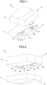
FIG. 1 is a view illustrating a press forming tool according to an embodiment of the present invention (part 1). -
FIG. 2 is a view illustrating the press forming tool according to the embodiment of the present invention (part 2) . -
FIG. 3 is a view illustrating the press forming tool according to the embodiment of the present invention (part 3) . -
FIG. 4 is a view illustrating the press forming tool according to the embodiment of the present invention (part 4) . -
FIG. 5 is a view illustrating a method of press forming according to the embodiment of the present invention. -
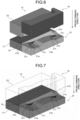
FIG. 6 is a view illustrating states of dies in a forming preparation step of the method of press forming according to the embodiment of the present invention (part 1) . -
FIG. 7 is a view illustrating states of dies in the forming preparation step of the method of press forming according to the embodiment of the present invention (part 2) . -
FIG. 8 is a view illustrating states of dies in an initial forming step of the method of press forming according to the embodiment of the present invention. -
FIG. 9 is an enlarged view of portion AA in the formed part in the initial forming step inFIG. 5 as viewed from a direction of a thick arrow. -
FIG. 10 is a view illustrating a mechanism of suppressing occurrence of wrinkles in the initial forming step. -
FIG. 11 is a view illustrating states of dies in a late forming step of the method of press forming according to the embodiment of the present invention. -
FIG. 12 is an enlarged view of portion BB in a target shape in the late forming step ofFIG. 5 as viewed from the direction of a thick arrow. -
FIG. 13 is a view illustrating a mechanism of suppressing occurrence of fractures in the late forming step. -
FIG. 14 is a view illustrating a target shape and a problem occurring in a forming process of the target shape according to the embodiment. -
FIG. 15 is a diagram illustrating a mechanism of occurrence of wrinkles and fractures in the forming process of the target shape illustrated inFIG. 14 . - Prior to the description of the press forming tool and the method of press forming according to the present embodiment, an example of a press forming part to be formed in the present invention will be described with reference to
FIGS. 14 and15 . Apress forming part 1 illustrated inFIG. 14 is drawn as a perspective view of a slide door rail which is an automotive part, and includes atop portion 3 and aflange portion 5. Thetop portion 3 has aconvex part 7 protruding outward in an in-plane direction and aconcave part 9 adjacent to theconvex part 7 and recessed inward in the in-plane direction. The outer periphery of thetop portion 3 is formed to be a convex and concaveouter edge part 11 including: a convexouter edge part 11a which is an outer peripheral side of theconvex part 7; a concaveouter edge part 11b which is an outer peripheral side of the concave part 9: and a connectingouter edge part 11c connecting the convexouter edge part 11a and the concaveouter edge part 11b to each other. Theflange portion 5 is formed on the convex and concaveouter edge part 11. In the case of an actual slide door rail, a bent portion is formed on an outer edge part of thetop portion 3 facing the convex and concaveouter edge part 11 where theflange portion 5 is formed. However,FIG. 14 omits illustration of the bent portion. - When such a
press forming part 1 is formed by a conventional method of press forming, theflange portion 5 formed in the convexouter edge part 11a subjected to shrink flange forming (portion a circled by a broken line in the drawing), and wrinkles are likely to occur due to the excess metal. On the other hand, theflange portion 5 formed in the concaveouter edge part 11b is subjected to stretch flange forming (portion b circled by a broken line in the drawing), and is likely to have fractures due to a material shortage. - A mechanism of occurrence of the wrinkles and the fractures will be described with reference to
FIG. 15. FIG. 15 is a diagram illustrating a material flow in the forming process in portion EE surrounded by the broken line inFIG. 14 , illustrating a top view (FIG. 15(a) ) and a side view of (FIG. 15(b) ) ofFIG. 14 . InFIG. 15 , a broken line is a tip of the blank before forming, and a solid line is an edge of theflange portion 5 formed into a target shape. Further, points D and B in the drawing are points corresponding to the R-finish(the boundary between a curve and a straight line) of the convexouter edge part 11a in the blank before forming, and corresponding intersections of lines perpendicular to the edge of the target shape from points D and B in the top view and the edge of the target shape are points D' and B'. Similarly, points A and E in the drawing are points corresponding to the R-finish of the concaveouter edge part 11b in the blank before forming, and corresponding points of intersection between a line perpendicular to the edge of the target shape from points E and A in the top view and the edge of the target shape are points A' and E'. As illustrated in the top view ofFIG. 15(a) , since the material flows substantially perpendicularly to the ridge line (bending line), the material flows in a direction in which the material gathers in portion a, and flows in a direction in which the material leaves in portion b. Accordingly, wrinkles are likely to occur in portion a, while fractures are likely to occur in portion b. - In order to solve such a problem, the inventors have considered that interposing a preformed part, which facilitates inflow of a material from a portion where shrink flange forming occurs to a portion where stretch flange forming occurs, in the middle of forming will enable avoidance of concentration of compressive strain and tensile strain in each of the portions, and have devised a press forming tool that can achieve this method of press forming. Specifically, the press forming tool has the following configuration.
- As illustrated in
FIG. 14 , for example, apress forming tool 13 according to the present embodiment forms apress forming part 1 including: atop portion 3 having a convex and concaveouter edge part 11 in which a convexouter edge part 11a protruding outward in an in-plane direction and a concaveouter edge part 11b recessed inward in the in-plane direction are continuous to each other via a connectingouter edge part 11c; and aflange portion 5 continuously formed on the convex and concaveouter edge part 11 of thetop portion 3. Further, as illustrated inFIGS. 1 to 4 , thepress forming tool 13 according to the present embodiment includes: anupper die 15 and alower die 17 for bend-forming theflange portion 5 along the convex and concave outer edge part 11 (FIG. 5 ); and alower pad 21 and anupper pad 23 that sandwich a blank 19 in cooperation with theupper die 15 and thelower die 17. Note that terms of the upper and lower in the upper die and the lower die just indicate a relative relationship, and thus, the positions are not necessarily upper or lower, but simply indicate that they are provided in a pair. With thepress forming tool 13 of the present embodiment, the blank 19 (FIG. 6 ) is placed on thelower die 17 and sandwiched by theupper pad 23, and theupper die 15 and thelower pad 21 are moved to perform bend-forming of theflange portion 5 at an outer edge of the blank 19. The bending edge portions of theupper die 15 and thelower die 17 are formed with convex and concave outer surfaces that protrude or recesses in the in-plane direction of the blank 19 to be placed, similarly to the convex and concaveouter edge parts 11 of thetop portion 3. - The
upper die 15 includes: a convex outer edgeflange forming portion 15a that forms theflange portion 5 in the convexouter edge part 11a; a concave outer edgeflange forming portion 15b that forms theflange portion 5 in the concaveouter edge part 11b; and a connecting outer edgeflange forming portion 15c that forms theflange portion 5 in the connectingouter edge part 11c (refer toFIG. 4 ). The convex outer edgeflange forming portion 15a protrudes in the press forming direction (downward inFIGS. 1 to 4 in the out-of-plane direction of the blank 19 to be placed) from the concave outer edgeflange forming portion 15b, while the connecting outer edgeflange forming portion 15c is inclined from the convex outer edgeflange forming portion 15a toward the concave outer edgeflange forming portion 15b (refer toFIGS. 2 and4 ). - The
lower pad 21 has a shape corresponding to each of the convex outer edgeflange forming portion 15a, the concave outer edgeflange forming portion 15b, and the connecting outer edgeflange forming portion 15c formed in theupper die 15. That is, a portion of thelower pad 21 corresponding to the convex outer edgeflange forming portion 15a of the upper die 15 (the portion also referred to as a lower pad convex outer edgeflange forming portion 21a) is more recessed in the press forming direction compared with a portion corresponding to the concave outer edgeflange forming portion 15b of the upper die 15 (the portion also referred to as a lower pad concave outer edgeflange forming portion 21b). Moreover, a portion corresponding to the connecting outer edgeflange forming portion 15c of the upper die 15 (the portion also referred to as a lower pad connecting outer edgeflange forming portion 21c) is inclined from the lower pad concave outer edgeflange forming portion 21b toward the lower pad convex outer edgeflange forming portion 21a (refer toFIGS. 1 and3 ) . - Next, a method of forming the slide door rail member illustrated in
FIG. 14 using the above-described apress forming tool 13 of the present embodiment will be described. As illustrated inFIG. 5 , the method of press forming of the present embodiment includes a forming preparation step S1 of setting the blank 19 in thepress forming tool 13, an initial forming step S3, and a late forming step S5. Hereinafter, each step will be described in detail with reference toFIGS. 5 to 13 . InFIGS. 7 ,8 , and11 illustrating the movement of the dies, theupper die 15 and theupper pad 23 are drawn as transparent perspective views in order to demonstrate the forming state of the blank 19. - In the forming preparation step S1, as illustrated in
FIG. 6 , a blank 19 made of a metal sheet is placed on thelower die 17, and as illustrated inFIG. 7 , a part of the blank 19 is sandwiched by using theupper pad 23. At this time, the uppermost surface (for example, the lower pad concave outer edgeflange forming portion 21b) of thelower pad 21 is flush with the upper surface oflower die 17. A portion of the blank 19 corresponding to thetop portion 3 is disposed on thelower die 17, while a portion of the blank 19 corresponding to theflange portion 5 is disposed on the lower pad concave outer edgeflange forming portion 21b of thelower pad 21. - In the initial forming step S3, as illustrated in
FIG. 8 , a part of the blank 19 is supported by thelower pad 21 in a state where a part of the blank 19 is sandwiched between theupper pad 23 and thelower die 17, and theupper die 15 is relatively moved in the press forming direction. With this operation, theflange portion 5 is formed in the convexouter edge part 11a by the convex outer edgeflange forming portion 15a, and atorsional shape portion 25 having a shape torsional toward the concaveouter edge part 11b is formed by the connecting outer edgeflange forming portion 15c continuously from theflange portion 5. - In the initial forming step S3, the
flange portion 5 is formed in the convexouter edge part 11a of thetop portion 3, but since the concaveouter edge part 11b is supported by the lower pad concave outer edgeflange forming portion 21b, theflange portion 5 is not formed. Therefore, instead of theflange portion 5, thetorsional shape portion 25 is formed on the connectingouter edge part 11c ranging from the convexouter edge part 11a to the concaveouter edge part 11b. As illustrated inFIG. 9 , thetorsional shape portion 25 is connected, on one end side, to theflange portion 5 formed on the convexouter edge part 11a, while being connected, the other end side, to thetop portion 3 as a flat portion, forming thetorsional shape portion 25 to have a torsional shape. At the time of forming thetorsional shape portion 25, as indicated by an arrow inFIG. 9 , a metal inflow occurs in a direction from theflange portion 5 side to be formed toward the flat portion, leading to alleviation of excess metal in the shrink flange forming and suppression of the occurrence of wrinkles. - A mechanism of occurrence of the material flow will be described with reference to
FIG. 10. FIG. 10 is a view illustrating the material flow in the forming process of portion CC surrounded by the broken line inFIG. 9 , illustrating a top view and a side view ofFIG. 9 . InFIG. 10 , a fine broken line is an edge of the blank before forming, a coarse broken line is an edge of thetorsional shape portion 25, and a solid line is an edge of the target shape. Points A to E and points A' to E' in the drawing are the same as those illustrated inFIG. 15 . That is, point A in the drawing is an R-finish of a curved portion in the blank 19, and is a tip position of thetorsional shape portion 25 with little deformation. Point B is a point corresponding to one R-finish of the blank portion having occurrence of shrink flange forming in a conventional case, and point B' is an intersection of a line extending perpendicularly to the edge of thetorsional shape portion 25 from point B in the top view and the edge of thetorsional shape portion 25. Point D is an R-finish of the curved portion of the blank 19, and point D' is an intersection of a line perpendicular to the edge of the target shape from point D in the top view and the edge of the target shape. - Due to the shrink flange forming, the distance from point B' to point D' is shorter than the distance from point B to point D (B'D' < BD), and thus, wrinkles are likely to occur in the
flange portion 5 formed in the convexouter edge part 11a due to the excess metal. On the other hand, since the distance from point A to point B' is longer than the distance from point A to point B (AB' > AB) in a three-dimensional view, the material is pulled toward point A and flows while deviating from "substantially perpendicular to the ridge line". Therefore, the material flow indicated by the arrow inFIG. 10 is generated, the material flow being closer to point A as compared with the conventional material flow indicated by the arrow in the wrinkle occurrence region inFIG. 15 . This material flow alleviates the excess metal in shrink flange forming during the initial forming step, leading to suppressing of occurrence of wrinkles. - In the late forming step S5, as illustrated in
FIG. 11 , theupper die 15 and thelower pad 21 are moved in the press forming direction. With this operation, thetorsional shape portion 25 is formed into theflange portion 5 by the connecting outer edgeflange forming portion 15c, while theflange portion 5 is formed in the concaveouter edge part 11b by the concave outer edgeflange forming portion 15b, achieving forming of the target shape. In the forming process of the late forming step S5, as indicated by a thick arrow inFIG. 12 , the metal inflow occurs from thetorsional shape portion 25 to the stretch flange forming portion, leading to alleviation of material shortage in the stretch flange forming portion and suppression of the occurrence of fractures. - A mechanism of occurrence of the material flow will be described with reference to
FIG. 13. FIG. 13 is a view illustrating the material flow in the forming process of portion DD surrounded by the broken line inFIG. 12 , illustrating a top view and a side view ofFIG. 12 . InFIG. 13 , a fine broken line is an edge of the blank before forming, a coarse broken line is an edge of thetorsional shape portion 25, and a solid line is an edge of theflange portion 5 in the target shape. - In addition, points A to E and points A' to E' in the drawing are the same as those illustrated in
FIGS. 15 and10 . That is, point A' in the drawing is an intersection of a line extending perpendicularly to the ridge line of the target shape in the top view from point A and the target shape. Point E is a point corresponding to one R-finish of the blank portion in which the conventional stretch flange forming occurs, and point E' is an intersection of a line perpendicular to the edge of the target shape from point E in the top view and the edge of the target shape. Due to the stretch flange forming, the distance from point A' to point E' is longer than the distance from point A to point E (A'E' > AE), and the material shortage is likely to cause an occurrence of fractures in theflange portion 5 formed in the concaveouter edge part 11b. On the other hand, since the distance from point D' to point E' is shorter than the distance from point D' to point E (D'E' < D'E) in a three-dimensional view, the material is pushed toward the A' side and flows while deviating from "substantially perpendicular to the ridge line". Therefore, the material flow indicated by the arrow inFIG. 13 is generated, the material flow being closer to point A as compared with the conventional material flow indicated by the arrow in the fracture occurrence region inFIG. 15 . This material flow alleviates the material shortage in the stretch flange forming during the late forming step S5, leading to suppression of occurrence of fractures. - As described above, with the
press forming tool 13 of the present embodiment, it is possible to form, during the initial stage of forming, theflange portion 5 in the convexouter edge part 11a by the convex outer edgeflange forming portion 15a and form thetorsional shape portion 25 having a torsional shape toward the concaveouter edge part 11b continuously from theflange portion 5 by the connecting outer edgeflange forming portion 15c, and possible to form, during the late stage of forming, thetorsional shape portion 25 into theflange portion 5 by the connecting outer edgeflange forming portion 15c and form theflange portion 5 in the concaveouter edge part 11b by the concave outer edgeflange forming portion 15b, achieving formation of the target shape. With this configuration, thetorsional shape portion 25 that promotes the material flow to the portion side of occurrence of the stretch flange forming is formed by first forming only the portion of occurrence of the shrink flange forming during the initial stage of forming, and the target shape can be formed by suppressing the material shortage due to the stretch flange forming by the material flow from thetorsional shape portion 25 by forming the portion of occurrence of the stretch flange forming during the late stage of forming. - In this manner, by dispersing the strain of a dangerous portion where the stretch flange fracture occurs and a dangerous portion where the shrink flange wrinkles occur, it is possible to suppress the occurrence of wrinkles due to shrink flange forming in the initial forming step S3, suppress occurrence of fractures due to the stretch flange forming in the late forming step S5, and suppress the occurrence of wrinkles and fractures throughout all the steps. In addition, it is possible to press forming using dies by a single action with a movement in a single direction, and leading to achievement of press forming with high efficiency.
- In order to confirm the effect of the present invention, press forming was performed with an example of a slide door rail member as illustrated in
FIG. 14 as a target shape. The material was a steel sheet having a tensile strength of 1180 MPa class and a thickness of 1.4 mm. First, as Comparative Example, a target shape was formed in one step without forming thetorsional shape portion 25, and press forming was performed by a method of crash forming by using pad (pad forming), in which the top portion was held with a pad (pressure pad). Next, as Example of the present invention, using thepress forming tool 13 described in the embodiment, press forming is performed, including steps of: an initial forming step S3 of forming theflange portion 5 in the convexouter edge part 11a and forming thetorsional shape portion 25 in the connectingouter edge part 11c; and a late forming step S5 of forming thetorsional shape portion 25 into theflange portion 5 and forming theflange portion 5 in the concaveouter edge part 11b. All the forming steps include a method of crash forming by using pad, in which the top portion was held with a pad. - In the case of Comparative Example, wrinkles occurred in portion a and fractures occurred in portion b illustrated in
FIG. 14 , and the target shape was not successfully obtained. In contrast, in Example of the present invention, the press forming part of high quality was successfully obtained with no fracture or wrinkles in theflange portion 5. As described above, the present invention is proven to be effective for suppressing stretch flange fracture and shrink flange wrinkles in formation of a press forming part having convex and concave parts in the in-plane direction on thetop portion 3. - According to the present invention, it is possible to provide a press forming tool and a method of press forming applicable to a press forming part having an occurrence of wrinkles and fractures in a flange itself and capable of simultaneously suppressing the wrinkles and fractures occurring in the flange.
-
- 1 PRESS FORMING PART
- 3 TOP PORTION
- 5 FLANGE PORTION
- 7 CONVEX PART
- 9 CONCAVE PART
- 11 CONVEX AND CONCAVE OUTER EDGE PART
- 11a CONVEX OUTER EDGE PART
- 11b CONCAVE OUTER EDGE PART
- 11c CONNECTING OUTER EDGE PART
- 13 TOOLS OF PRESS FORMING
- 15 UPPER DIE
- 15a CONVEX OUTER EDGE FLANGE FORMING PORTION
- 15b CONCAVE OUTER EDGE FLANGE FORMING PORTION
- 15c CONNECTING OUTER EDGE FLANGE FORMING PORTION
- 17 LOWER DIE
- 19 BLANK
- 21 LOWER PAD
- 21a LOWER PAD CONVEX OUTER EDGE FLANGE FORMING PORTION
- 21b LOWER PAD CONCAVE OUTER EDGE FLANGE FORMING PORTION
- 21c LOWER PAD CONNECTING OUTER EDGE FLANGE FORMING PORTION
- 23 UPPER PAD
- 25 TORSIONAL SHAPE PORTION
Claims (2)
- A press forming tool for forming a press forming part, the press forming part including: a top portion having a convex and concave outer edge part in which a convex outer edge part protruding outward in an in-plane direction and a concave outer edge part recessed inward in the in-plane direction are continuous to each other via a connecting outer edge part; and a flange portion continuously formed in the convex and concave outer edge part of the top portion, the press forming tool comprising:an upper die and a lower die to be used for bend-forming of the flange portion along the convex and concave outer edge part; anda lower pad and an upper pad configured to sandwich a blank in cooperation with the upper die and the lower die, whereinthe upper die includes:a convex outer edge flange forming portion configured to form the flange portion in the convex outer edge part;a concave outer edge flange forming portion configured to form the flange portion in the concave outer edge part; anda connecting outer edge flange forming portion configured to form the flange portion in the connecting outer edge part, the convex outer edge flange forming portion protruding in a press forming direction from the concave outer edge flange forming portion, with the connecting outer edge flange forming portion inclined from the convex outer edge flange forming portion toward the concave outer edge flange forming portion,the lower pad has a shape corresponding to each of the convex outer edge flange forming portion, the concave outer edge flange forming portion, and the connecting outer edge flange forming portion formed in the upper die, andpress forming is performed such thatduring an initial stage of forming, the flange portion is formed on the convex outer edge part by the convex outer edge flange forming portion, and a torsional shape portion having a torsional shape toward the concave outer edge part is formed continuously from the flange portion by the connecting outer edge flange forming portion, andduring a late stage of forming, the torsional shape portion is formed into the flange portion by the connecting outer edge flange forming portion, and the flange portion is formed in the concave outer edge part by the concave outer edge flange forming portion so as to achieve formation of a target shape.
- A method of press forming for forming a press forming part by using the press forming tool according to claim 1, the press forming part including: a top portion having a convex and concave outer edge part in which a convex outer edge part protruding outward in an in-plane direction and a concave outer edge part recessed inward in the in-plane direction are continuous to each other via a connecting outer edge part; and a flange portion continuously formed on the convex and concave outer edge part of the top portion, the method of press forming comprising:an initial forming step of forming the flange portion in the convex outer edge part by the convex outer edge flange forming portion and forming a torsional shape portion having a torsional shape toward the concave outer edge part by the connecting outer edge flange forming portion so as to be continuous from the flange portion, by moving the upper die in a press forming direction in a state where a part of a blank is sandwiched by the upper pad and the lower die and a part of the blank is supported by the lower pad; anda late forming step of moving the upper die and the lower pad in the press forming direction to form the torsional shape portion into the flange portion by the connecting outer edge flange forming portion and to form the flange portion in the concave outer edge part by the concave outer edge flange forming portion so as to achieve formation of a target shape.
Applications Claiming Priority (2)
| Application Number | Priority Date | Filing Date | Title |
|---|---|---|---|
| JP2020090158A JP6981502B2 (en) | 2020-05-23 | 2020-05-23 | Press molding die, press molding method |
| PCT/JP2021/014848 WO2021241025A1 (en) | 2020-05-23 | 2021-04-08 | Press-forming mold and press-forming method |
Publications (3)
| Publication Number | Publication Date |
|---|---|
| EP4137245A1 true EP4137245A1 (en) | 2023-02-22 |
| EP4137245A4 EP4137245A4 (en) | 2023-10-11 |
| EP4137245B1 EP4137245B1 (en) | 2025-07-02 |
Family
ID=78744330
Family Applications (1)
| Application Number | Title | Priority Date | Filing Date |
|---|---|---|---|
| EP21813956.6A Active EP4137245B1 (en) | 2020-05-23 | 2021-04-08 | Press-forming mold and press-forming method |
Country Status (7)
| Country | Link |
|---|---|
| US (1) | US12233444B2 (en) |
| EP (1) | EP4137245B1 (en) |
| JP (1) | JP6981502B2 (en) |
| KR (1) | KR102861496B1 (en) |
| CN (1) | CN115666811B (en) |
| MX (1) | MX2022014334A (en) |
| WO (1) | WO2021241025A1 (en) |
Families Citing this family (3)
| Publication number | Priority date | Publication date | Assignee | Title |
|---|---|---|---|---|
| JP2025121798A (en) * | 2024-02-07 | 2025-08-20 | 有限会社石川鉄工所 | Press die design support system |
| JP7655429B1 (en) * | 2024-04-08 | 2025-04-02 | Jfeスチール株式会社 | Manufacturing method of press-molded products |
| WO2026067979A1 (en) * | 2024-09-26 | 2026-04-02 | DeepForm Limited | Forming of sheet metal |
Family Cites Families (18)
| Publication number | Priority date | Publication date | Assignee | Title |
|---|---|---|---|---|
| JPS5976625A (en) * | 1982-10-26 | 1984-05-01 | Toyota Motor Corp | Working die for bending curved flange |
| JPS60210326A (en) * | 1984-04-03 | 1985-10-22 | Komatsu Ltd | Flange bending method for curved surfaces |
| JPS61222640A (en) * | 1985-03-29 | 1986-10-03 | Nissan Motor Co Ltd | Forming method of channel and forming metal die |
| FR2655890A1 (en) * | 1989-12-18 | 1991-06-21 | Lorraine Laminage | PROCESS FOR THE PREPARATION OF A NON-DEVELOPABLE SHAPE PART FROM A SHEET OF SHEET AND SHAPED PART OBTAINED BY THIS PROCESS. |
| JP5270816B2 (en) * | 2006-03-22 | 2013-08-21 | プレス工業株式会社 | Channel material |
| JP2008264838A (en) * | 2007-04-20 | 2008-11-06 | Nissan Motor Co Ltd | Press mold and press molding method |
| CN101920285B (en) * | 2010-06-08 | 2012-05-23 | 东莞市旗丰消声器有限公司 | One-step deep drawing forming process method for oil tank half-shell workpiece |
| JP2014039957A (en) * | 2012-07-27 | 2014-03-06 | Nisshin Steel Co Ltd | Press working method of flanged molding member, and bending tool for use in the method |
| TWI574755B (en) * | 2013-03-21 | 2017-03-21 | Nippon Steel & Sumitomo Metal Corp | A method of manufacturing a press-formed member, and a press-forming device |
| RU2628595C1 (en) * | 2013-10-09 | 2017-08-21 | Ниппон Стил Энд Сумитомо Метал Корпорейшн | Method of press-formed product manufacture and device for forming by pressing |
| JP6281670B1 (en) | 2016-06-27 | 2018-02-21 | 新日鐵住金株式会社 | Press part manufacturing method and manufacturing apparatus |
| US20180043413A1 (en) * | 2016-08-12 | 2018-02-15 | Uacj Corporation | Press-forming die |
| JP6973236B2 (en) | 2018-03-29 | 2021-11-24 | Jfeスチール株式会社 | Press molding method |
| EP3804875B1 (en) * | 2018-05-24 | 2025-07-02 | JFE Steel Corporation | Method for manufacturing pressed component |
| JP7133364B2 (en) * | 2018-05-31 | 2022-09-08 | 群栄化学工業株式会社 | Polyimine, varnish, film and method for producing the same, cured film and method for producing the same, and laminate and method for producing the same |
| WO2020026356A1 (en) * | 2018-07-31 | 2020-02-06 | 日本製鉄株式会社 | Stretch flange forming tool and stretch flange forming method employing same, and member with stretch flange |
| JP7247975B2 (en) * | 2020-07-06 | 2023-03-29 | 株式会社ニコン | Imaging element and imaging device |
| JP7537966B2 (en) * | 2020-09-16 | 2024-08-21 | 東プレ株式会社 | Manufacturing method of press-molded product and press die |
-
2020
- 2020-05-23 JP JP2020090158A patent/JP6981502B2/en active Active
-
2021
- 2021-04-08 WO PCT/JP2021/014848 patent/WO2021241025A1/en not_active Ceased
- 2021-04-08 CN CN202180035890.8A patent/CN115666811B/en active Active
- 2021-04-08 EP EP21813956.6A patent/EP4137245B1/en active Active
- 2021-04-08 MX MX2022014334A patent/MX2022014334A/en unknown
- 2021-04-08 US US17/925,961 patent/US12233444B2/en active Active
- 2021-04-08 KR KR1020227040620A patent/KR102861496B1/en active Active
Also Published As
| Publication number | Publication date |
|---|---|
| US20230182189A1 (en) | 2023-06-15 |
| US12233444B2 (en) | 2025-02-25 |
| CN115666811A (en) | 2023-01-31 |
| JP6981502B2 (en) | 2021-12-15 |
| KR20230002914A (en) | 2023-01-05 |
| EP4137245B1 (en) | 2025-07-02 |
| EP4137245A4 (en) | 2023-10-11 |
| MX2022014334A (en) | 2022-12-13 |
| KR102861496B1 (en) | 2025-09-17 |
| WO2021241025A1 (en) | 2021-12-02 |
| JP2021184998A (en) | 2021-12-09 |
| CN115666811B (en) | 2025-07-22 |
Similar Documents
| Publication | Publication Date | Title |
|---|---|---|
| EP3202504B1 (en) | Method for producing press-molded article and production line | |
| EP3804875B1 (en) | Method for manufacturing pressed component | |
| EP4140614B1 (en) | Press forming method | |
| EP4137245B1 (en) | Press-forming mold and press-forming method | |
| CN109952165B (en) | Method and apparatus for manufacturing press-formed article | |
| TWI624315B (en) | Manufacturing method of press-formed product, press-formed product, and pressing device | |
| CN111727089B (en) | Method for manufacturing press-molded member, press-molding device, and metal plate for press-molding | |
| CN107427884B (en) | Stamping forming method and stamping forming die | |
| US12263515B2 (en) | Press forming tool and press forming method | |
| CN107635684A (en) | Impact forming method and punch-forming mold | |
| WO2021205692A1 (en) | Press-forming method and press-formed product | |
| EP3778053A1 (en) | Designing method for press-molded article, press-molding die, press-molded article, and production method for press-molded article | |
| US10858048B2 (en) | Structural member and method of production of same | |
| EP4155005B1 (en) | Press forming method | |
| EP3778057A1 (en) | Rigidity improvement method for press-molded article, press-molding die, press-molded article, and production method for press-molded article | |
| JP7593385B2 (en) | Press molding method and manufacturing method of press molded product | |
| WO2022137630A1 (en) | Press-forming method |
Legal Events
| Date | Code | Title | Description |
|---|---|---|---|
| STAA | Information on the status of an ep patent application or granted ep patent |
Free format text: STATUS: THE INTERNATIONAL PUBLICATION HAS BEEN MADE |
|
| PUAI | Public reference made under article 153(3) epc to a published international application that has entered the european phase |
Free format text: ORIGINAL CODE: 0009012 |
|
| STAA | Information on the status of an ep patent application or granted ep patent |
Free format text: STATUS: REQUEST FOR EXAMINATION WAS MADE |
|
| 17P | Request for examination filed |
Effective date: 20221117 |
|
| AK | Designated contracting states |
Kind code of ref document: A1 Designated state(s): AL AT BE BG CH CY CZ DE DK EE ES FI FR GB GR HR HU IE IS IT LI LT LU LV MC MK MT NL NO PL PT RO RS SE SI SK SM TR |
|
| DAV | Request for validation of the european patent (deleted) | ||
| DAX | Request for extension of the european patent (deleted) | ||
| A4 | Supplementary search report drawn up and despatched |
Effective date: 20230913 |
|
| RIC1 | Information provided on ipc code assigned before grant |
Ipc: B21D 19/08 20060101ALI20230907BHEP Ipc: B21D 22/26 20060101ALI20230907BHEP Ipc: B21D 24/00 20060101AFI20230907BHEP |
|
| STAA | Information on the status of an ep patent application or granted ep patent |
Free format text: STATUS: EXAMINATION IS IN PROGRESS |
|
| 17Q | First examination report despatched |
Effective date: 20240219 |
|
| GRAP | Despatch of communication of intention to grant a patent |
Free format text: ORIGINAL CODE: EPIDOSNIGR1 |
|
| STAA | Information on the status of an ep patent application or granted ep patent |
Free format text: STATUS: GRANT OF PATENT IS INTENDED |
|
| INTG | Intention to grant announced |
Effective date: 20250325 |
|
| GRAS | Grant fee paid |
Free format text: ORIGINAL CODE: EPIDOSNIGR3 |
|
| GRAA | (expected) grant |
Free format text: ORIGINAL CODE: 0009210 |
|
| STAA | Information on the status of an ep patent application or granted ep patent |
Free format text: STATUS: THE PATENT HAS BEEN GRANTED |
|
| AK | Designated contracting states |
Kind code of ref document: B1 Designated state(s): AL AT BE BG CH CY CZ DE DK EE ES FI FR GB GR HR HU IE IS IT LI LT LU LV MC MK MT NL NO PL PT RO RS SE SI SK SM TR |
|
| REG | Reference to a national code |
Ref country code: GB Ref legal event code: FG4D |
|
| REG | Reference to a national code |
Ref country code: CH Ref legal event code: EP |
|
| REG | Reference to a national code |
Ref country code: DE Ref legal event code: R096 Ref document number: 602021033497 Country of ref document: DE |
|
| REG | Reference to a national code |
Ref country code: IE Ref legal event code: FG4D |
|
| REG | Reference to a national code |
Ref country code: NL Ref legal event code: MP Effective date: 20250702 |
|
| PG25 | Lapsed in a contracting state [announced via postgrant information from national office to epo] |
Ref country code: PT Free format text: LAPSE BECAUSE OF FAILURE TO SUBMIT A TRANSLATION OF THE DESCRIPTION OR TO PAY THE FEE WITHIN THE PRESCRIBED TIME-LIMIT Effective date: 20251103 |
|
| PG25 | Lapsed in a contracting state [announced via postgrant information from national office to epo] |
Ref country code: NL Free format text: LAPSE BECAUSE OF FAILURE TO SUBMIT A TRANSLATION OF THE DESCRIPTION OR TO PAY THE FEE WITHIN THE PRESCRIBED TIME-LIMIT Effective date: 20250702 |
|
| REG | Reference to a national code |
Ref country code: AT Ref legal event code: MK05 Ref document number: 1808697 Country of ref document: AT Kind code of ref document: T Effective date: 20250702 |
|
| PG25 | Lapsed in a contracting state [announced via postgrant information from national office to epo] |
Ref country code: IS Free format text: LAPSE BECAUSE OF FAILURE TO SUBMIT A TRANSLATION OF THE DESCRIPTION OR TO PAY THE FEE WITHIN THE PRESCRIBED TIME-LIMIT Effective date: 20251102 |
|
| PG25 | Lapsed in a contracting state [announced via postgrant information from national office to epo] |
Ref country code: NO Free format text: LAPSE BECAUSE OF FAILURE TO SUBMIT A TRANSLATION OF THE DESCRIPTION OR TO PAY THE FEE WITHIN THE PRESCRIBED TIME-LIMIT Effective date: 20251002 |
|
| REG | Reference to a national code |
Ref country code: LT Ref legal event code: MG9D |
|
| PG25 | Lapsed in a contracting state [announced via postgrant information from national office to epo] |
Ref country code: AT Free format text: LAPSE BECAUSE OF FAILURE TO SUBMIT A TRANSLATION OF THE DESCRIPTION OR TO PAY THE FEE WITHIN THE PRESCRIBED TIME-LIMIT Effective date: 20250702 |
|
| PG25 | Lapsed in a contracting state [announced via postgrant information from national office to epo] |
Ref country code: FI Free format text: LAPSE BECAUSE OF FAILURE TO SUBMIT A TRANSLATION OF THE DESCRIPTION OR TO PAY THE FEE WITHIN THE PRESCRIBED TIME-LIMIT Effective date: 20250702 |
|
| PG25 | Lapsed in a contracting state [announced via postgrant information from national office to epo] |
Ref country code: HR Free format text: LAPSE BECAUSE OF FAILURE TO SUBMIT A TRANSLATION OF THE DESCRIPTION OR TO PAY THE FEE WITHIN THE PRESCRIBED TIME-LIMIT Effective date: 20250702 |
|
| PG25 | Lapsed in a contracting state [announced via postgrant information from national office to epo] |
Ref country code: GR Free format text: LAPSE BECAUSE OF FAILURE TO SUBMIT A TRANSLATION OF THE DESCRIPTION OR TO PAY THE FEE WITHIN THE PRESCRIBED TIME-LIMIT Effective date: 20251003 |
|
| PG25 | Lapsed in a contracting state [announced via postgrant information from national office to epo] |
Ref country code: SE Free format text: LAPSE BECAUSE OF FAILURE TO SUBMIT A TRANSLATION OF THE DESCRIPTION OR TO PAY THE FEE WITHIN THE PRESCRIBED TIME-LIMIT Effective date: 20250702 Ref country code: CZ Free format text: LAPSE BECAUSE OF FAILURE TO SUBMIT A TRANSLATION OF THE DESCRIPTION OR TO PAY THE FEE WITHIN THE PRESCRIBED TIME-LIMIT Effective date: 20250702 |
|
| PG25 | Lapsed in a contracting state [announced via postgrant information from national office to epo] |
Ref country code: LV Free format text: LAPSE BECAUSE OF FAILURE TO SUBMIT A TRANSLATION OF THE DESCRIPTION OR TO PAY THE FEE WITHIN THE PRESCRIBED TIME-LIMIT Effective date: 20250702 |
|
| PG25 | Lapsed in a contracting state [announced via postgrant information from national office to epo] |
Ref country code: BG Free format text: LAPSE BECAUSE OF FAILURE TO SUBMIT A TRANSLATION OF THE DESCRIPTION OR TO PAY THE FEE WITHIN THE PRESCRIBED TIME-LIMIT Effective date: 20250702 Ref country code: PL Free format text: LAPSE BECAUSE OF FAILURE TO SUBMIT A TRANSLATION OF THE DESCRIPTION OR TO PAY THE FEE WITHIN THE PRESCRIBED TIME-LIMIT Effective date: 20250702 |
|
| PG25 | Lapsed in a contracting state [announced via postgrant information from national office to epo] |
Ref country code: RS Free format text: LAPSE BECAUSE OF FAILURE TO SUBMIT A TRANSLATION OF THE DESCRIPTION OR TO PAY THE FEE WITHIN THE PRESCRIBED TIME-LIMIT Effective date: 20251002 |
|
| PG25 | Lapsed in a contracting state [announced via postgrant information from national office to epo] |
Ref country code: ES Free format text: LAPSE BECAUSE OF FAILURE TO SUBMIT A TRANSLATION OF THE DESCRIPTION OR TO PAY THE FEE WITHIN THE PRESCRIBED TIME-LIMIT Effective date: 20250702 |
|
| PG25 | Lapsed in a contracting state [announced via postgrant information from national office to epo] |
Ref country code: SM Free format text: LAPSE BECAUSE OF FAILURE TO SUBMIT A TRANSLATION OF THE DESCRIPTION OR TO PAY THE FEE WITHIN THE PRESCRIBED TIME-LIMIT Effective date: 20250702 |
|
| PG25 | Lapsed in a contracting state [announced via postgrant information from national office to epo] |
Ref country code: DK Free format text: LAPSE BECAUSE OF FAILURE TO SUBMIT A TRANSLATION OF THE DESCRIPTION OR TO PAY THE FEE WITHIN THE PRESCRIBED TIME-LIMIT Effective date: 20250702 |
|
| PG25 | Lapsed in a contracting state [announced via postgrant information from national office to epo] |
Ref country code: IT Free format text: LAPSE BECAUSE OF FAILURE TO SUBMIT A TRANSLATION OF THE DESCRIPTION OR TO PAY THE FEE WITHIN THE PRESCRIBED TIME-LIMIT Effective date: 20250702 |
|
| PGFP | Annual fee paid to national office [announced via postgrant information from national office to epo] |
Ref country code: FR Payment date: 20260309 Year of fee payment: 6 |
|
| PG25 | Lapsed in a contracting state [announced via postgrant information from national office to epo] |
Ref country code: EE Free format text: LAPSE BECAUSE OF FAILURE TO SUBMIT A TRANSLATION OF THE DESCRIPTION OR TO PAY THE FEE WITHIN THE PRESCRIBED TIME-LIMIT Effective date: 20250702 Ref country code: SK Free format text: LAPSE BECAUSE OF FAILURE TO SUBMIT A TRANSLATION OF THE DESCRIPTION OR TO PAY THE FEE WITHIN THE PRESCRIBED TIME-LIMIT Effective date: 20250702 |
|
| PLBE | No opposition filed within time limit |
Free format text: ORIGINAL CODE: 0009261 |
|
| STAA | Information on the status of an ep patent application or granted ep patent |
Free format text: STATUS: NO OPPOSITION FILED WITHIN TIME LIMIT |