EP4137219A1 - Impeller rotor configured with seal land of different material than the rotor - Google Patents
Impeller rotor configured with seal land of different material than the rotor Download PDFInfo
- Publication number
- EP4137219A1 EP4137219A1 EP22188262.4A EP22188262A EP4137219A1 EP 4137219 A1 EP4137219 A1 EP 4137219A1 EP 22188262 A EP22188262 A EP 22188262A EP 4137219 A1 EP4137219 A1 EP 4137219A1
- Authority
- EP
- European Patent Office
- Prior art keywords
- seal
- impeller rotor
- rotor
- seal land
- land
- Prior art date
- Legal status (The legal status is an assumption and is not a legal conclusion. Google has not performed a legal analysis and makes no representation as to the accuracy of the status listed.)
- Pending
Links
- 239000000463 material Substances 0.000 title claims abstract description 53
- 230000003068 static effect Effects 0.000 claims description 19
- 239000011248 coating agent Substances 0.000 claims description 7
- 238000000576 coating method Methods 0.000 claims description 7
- 229910000831 Steel Inorganic materials 0.000 claims description 4
- 229910052782 aluminium Inorganic materials 0.000 claims description 4
- XAGFODPZIPBFFR-UHFFFAOYSA-N aluminium Chemical compound [Al] XAGFODPZIPBFFR-UHFFFAOYSA-N 0.000 claims description 4
- 239000010959 steel Substances 0.000 claims description 4
- 239000007788 liquid Substances 0.000 description 22
- 239000012530 fluid Substances 0.000 description 16
- -1 but not limited to Inorganic materials 0.000 description 4
- 229910052751 metal Inorganic materials 0.000 description 3
- 239000002184 metal Substances 0.000 description 3
- 230000037361 pathway Effects 0.000 description 3
- 229910000838 Al alloy Inorganic materials 0.000 description 2
- 238000005299 abrasion Methods 0.000 description 2
- 230000001154 acute effect Effects 0.000 description 2
- 239000000654 additive Substances 0.000 description 2
- 230000000996 additive effect Effects 0.000 description 2
- 239000003562 lightweight material Substances 0.000 description 2
- 239000000314 lubricant Substances 0.000 description 2
- 238000000034 method Methods 0.000 description 2
- 239000010935 stainless steel Substances 0.000 description 2
- 229910001220 stainless steel Inorganic materials 0.000 description 2
- 241000270730 Alligator mississippiensis Species 0.000 description 1
- 230000015572 biosynthetic process Effects 0.000 description 1
Images




Classifications
-
- F—MECHANICAL ENGINEERING; LIGHTING; HEATING; WEAPONS; BLASTING
- F02—COMBUSTION ENGINES; HOT-GAS OR COMBUSTION-PRODUCT ENGINE PLANTS
- F02C—GAS-TURBINE PLANTS; AIR INTAKES FOR JET-PROPULSION PLANTS; CONTROLLING FUEL SUPPLY IN AIR-BREATHING JET-PROPULSION PLANTS
- F02C7/00—Features, components parts, details or accessories, not provided for in, or of interest apart form groups F02C1/00 - F02C6/00; Air intakes for jet-propulsion plants
- F02C7/32—Arrangement, mounting, or driving, of auxiliaries
-
- F—MECHANICAL ENGINEERING; LIGHTING; HEATING; WEAPONS; BLASTING
- F04—POSITIVE - DISPLACEMENT MACHINES FOR LIQUIDS; PUMPS FOR LIQUIDS OR ELASTIC FLUIDS
- F04D—NON-POSITIVE-DISPLACEMENT PUMPS
- F04D9/00—Priming; Preventing vapour lock
- F04D9/001—Preventing vapour lock
- F04D9/002—Preventing vapour lock by means in the very pump
- F04D9/003—Preventing vapour lock by means in the very pump separating and removing the vapour
-
- B—PERFORMING OPERATIONS; TRANSPORTING
- B01—PHYSICAL OR CHEMICAL PROCESSES OR APPARATUS IN GENERAL
- B01D—SEPARATION
- B01D19/00—Degasification of liquids
- B01D19/0042—Degasification of liquids modifying the liquid flow
- B01D19/0052—Degasification of liquids modifying the liquid flow in rotating vessels, vessels containing movable parts or in which centrifugal movement is caused
-
- F—MECHANICAL ENGINEERING; LIGHTING; HEATING; WEAPONS; BLASTING
- F04—POSITIVE - DISPLACEMENT MACHINES FOR LIQUIDS; PUMPS FOR LIQUIDS OR ELASTIC FLUIDS
- F04D—NON-POSITIVE-DISPLACEMENT PUMPS
- F04D29/00—Details, component parts, or accessories
- F04D29/08—Sealings
- F04D29/086—Sealings especially adapted for liquid pumps
-
- F—MECHANICAL ENGINEERING; LIGHTING; HEATING; WEAPONS; BLASTING
- F04—POSITIVE - DISPLACEMENT MACHINES FOR LIQUIDS; PUMPS FOR LIQUIDS OR ELASTIC FLUIDS
- F04D—NON-POSITIVE-DISPLACEMENT PUMPS
- F04D29/00—Details, component parts, or accessories
- F04D29/08—Sealings
- F04D29/10—Shaft sealings
- F04D29/12—Shaft sealings using sealing-rings
-
- F—MECHANICAL ENGINEERING; LIGHTING; HEATING; WEAPONS; BLASTING
- F04—POSITIVE - DISPLACEMENT MACHINES FOR LIQUIDS; PUMPS FOR LIQUIDS OR ELASTIC FLUIDS
- F04D—NON-POSITIVE-DISPLACEMENT PUMPS
- F04D29/00—Details, component parts, or accessories
- F04D29/18—Rotors
- F04D29/20—Mounting rotors on shafts
-
- F—MECHANICAL ENGINEERING; LIGHTING; HEATING; WEAPONS; BLASTING
- F04—POSITIVE - DISPLACEMENT MACHINES FOR LIQUIDS; PUMPS FOR LIQUIDS OR ELASTIC FLUIDS
- F04D—NON-POSITIVE-DISPLACEMENT PUMPS
- F04D29/00—Details, component parts, or accessories
- F04D29/18—Rotors
- F04D29/22—Rotors specially for centrifugal pumps
- F04D29/2261—Rotors specially for centrifugal pumps with special measures
- F04D29/2288—Rotors specially for centrifugal pumps with special measures for comminuting, mixing or separating
-
- F—MECHANICAL ENGINEERING; LIGHTING; HEATING; WEAPONS; BLASTING
- F04—POSITIVE - DISPLACEMENT MACHINES FOR LIQUIDS; PUMPS FOR LIQUIDS OR ELASTIC FLUIDS
- F04D—NON-POSITIVE-DISPLACEMENT PUMPS
- F04D31/00—Pumping liquids and elastic fluids at the same time
-
- F—MECHANICAL ENGINEERING; LIGHTING; HEATING; WEAPONS; BLASTING
- F05—INDEXING SCHEMES RELATING TO ENGINES OR PUMPS IN VARIOUS SUBCLASSES OF CLASSES F01-F04
- F05D—INDEXING SCHEME FOR ASPECTS RELATING TO NON-POSITIVE-DISPLACEMENT MACHINES OR ENGINES, GAS-TURBINES OR JET-PROPULSION PLANTS
- F05D2240/00—Components
- F05D2240/55—Seals
-
- F—MECHANICAL ENGINEERING; LIGHTING; HEATING; WEAPONS; BLASTING
- F05—INDEXING SCHEMES RELATING TO ENGINES OR PUMPS IN VARIOUS SUBCLASSES OF CLASSES F01-F04
- F05D—INDEXING SCHEME FOR ASPECTS RELATING TO NON-POSITIVE-DISPLACEMENT MACHINES OR ENGINES, GAS-TURBINES OR JET-PROPULSION PLANTS
- F05D2240/00—Components
- F05D2240/60—Shafts
- F05D2240/61—Hollow
-
- F—MECHANICAL ENGINEERING; LIGHTING; HEATING; WEAPONS; BLASTING
- F05—INDEXING SCHEMES RELATING TO ENGINES OR PUMPS IN VARIOUS SUBCLASSES OF CLASSES F01-F04
- F05D—INDEXING SCHEME FOR ASPECTS RELATING TO NON-POSITIVE-DISPLACEMENT MACHINES OR ENGINES, GAS-TURBINES OR JET-PROPULSION PLANTS
- F05D2260/00—Function
- F05D2260/60—Fluid transfer
- F05D2260/609—Deoiling or demisting
-
- F—MECHANICAL ENGINEERING; LIGHTING; HEATING; WEAPONS; BLASTING
- F05—INDEXING SCHEMES RELATING TO ENGINES OR PUMPS IN VARIOUS SUBCLASSES OF CLASSES F01-F04
- F05D—INDEXING SCHEME FOR ASPECTS RELATING TO NON-POSITIVE-DISPLACEMENT MACHINES OR ENGINES, GAS-TURBINES OR JET-PROPULSION PLANTS
- F05D2300/00—Materials; Properties thereof
- F05D2300/10—Metals, alloys or intermetallic compounds
- F05D2300/17—Alloys
- F05D2300/171—Steel alloys
-
- F—MECHANICAL ENGINEERING; LIGHTING; HEATING; WEAPONS; BLASTING
- F05—INDEXING SCHEMES RELATING TO ENGINES OR PUMPS IN VARIOUS SUBCLASSES OF CLASSES F01-F04
- F05D—INDEXING SCHEME FOR ASPECTS RELATING TO NON-POSITIVE-DISPLACEMENT MACHINES OR ENGINES, GAS-TURBINES OR JET-PROPULSION PLANTS
- F05D2300/00—Materials; Properties thereof
- F05D2300/10—Metals, alloys or intermetallic compounds
- F05D2300/17—Alloys
- F05D2300/173—Aluminium alloys, e.g. AlCuMgPb
-
- F—MECHANICAL ENGINEERING; LIGHTING; HEATING; WEAPONS; BLASTING
- F16—ENGINEERING ELEMENTS AND UNITS; GENERAL MEASURES FOR PRODUCING AND MAINTAINING EFFECTIVE FUNCTIONING OF MACHINES OR INSTALLATIONS; THERMAL INSULATION IN GENERAL
- F16J—PISTONS; CYLINDERS; SEALINGS
- F16J15/00—Sealings
- F16J15/16—Sealings between relatively-moving surfaces
- F16J15/32—Sealings between relatively-moving surfaces with elastic sealings, e.g. O-rings
- F16J15/3204—Sealings between relatively-moving surfaces with elastic sealings, e.g. O-rings with at least one lip
- F16J15/3208—Sealings between relatively-moving surfaces with elastic sealings, e.g. O-rings with at least one lip provided with tension elements, e.g. elastic rings
- F16J15/3212—Sealings between relatively-moving surfaces with elastic sealings, e.g. O-rings with at least one lip provided with tension elements, e.g. elastic rings with metal springs
Definitions
- This disclosure relates generally to rotational equipment and, more particularly, to a rotational equipment device with an impeller.
- Rotational equipment such as a gas turbine engine may include a deaerator for separating a fluid into its liquid and gas components.
- deaerator for separating a fluid into its liquid and gas components.
- Various types and configurations of deaerators are known in the art. While these known deaerators have various benefits, there is still room in the art for improvement. For example, there is a need for a light-weight, wear resistant rotor assembly for a deaerator.
- an assembly for a turbine engine.
- This turbine engine assembly includes an impeller rotor, a seal land and a lip seal.
- the impeller rotor is configured to rotate about a rotational axis.
- the impeller rotor is configured from or otherwise includes impeller rotor material.
- the seal land extends axially along and circumferentially about the rotational axis.
- the seal land is mechanically attached to and rotatable with the impeller rotor.
- the seal land is configured from or otherwise includes seal land material that is different than the impeller rotor material.
- the lip seal radially engages the seal land.
- This turbine engine assembly includes an impeller rotor, a seal land and a lip seal.
- the impeller rotor is configured to rotate about a rotational axis.
- the impeller rotor is configured from or otherwise includes impeller rotor material.
- the seal land is rotatable with and projects axially along the rotational axis out from the impeller rotor.
- the seal land is configured from or otherwise includes seal land material that is different than the impeller rotor material.
- the lip seal radially engages the impeller rotor material.
- This turbine engine assembly includes a deaerator impeller rotor, a seal land and a stationary seal element.
- the deaerator impeller rotor is configured to rotate about a rotational axis.
- the deaerator impeller rotor is configured from or otherwise includes impeller rotor material.
- the seal land extends axially along and circumferentially about the rotational axis.
- the seal land is mechanically attached to and rotatable with the deaerator impeller rotor.
- the seal land is configured from or otherwise includes seal land material that is different than the impeller rotor material.
- the stationary seal element radially contacts the seal land.
- the seal land may include a base and a hard coating on the base.
- the base may be formed integrally with the impeller rotor.
- the hard coating may be configured from or otherwise include the seal land material.
- the seal land may project into a bore of and may be mechanically attached to the impeller rotor.
- the impeller rotor material may be configured from or otherwise include aluminum.
- the seal land material may be configured from or otherwise include steel.
- the impeller rotor may be configured as a deaerator impeller rotor.
- the lip seal may include a seal base and a seal leg.
- the seal leg may be axially cantilevered from the seal base.
- the seal leg may include a tip that radially contacts an outer surface of the seal land.
- the lip seal may also include a biasing element extending circumferentially about and radially engaging the seal leg.
- the biasing element may be configured to bias the seal leg radially inward against the outer surface of the seal land.
- the assembly may include a ring seal element configured to form a sealed interface with and between the impeller rotor and the seal land.
- the seal land may engage the impeller rotor through an interference fit.
- a rotor bore may extend axially along the rotational axis into the impeller rotor.
- the seal land may include a mount that projects axially along the rotational axis into the rotor bore.
- the mount may be mechanically attached to the impeller rotor.
- the mount may be axially clamped to the impeller rotor.
- a fastener may rotationally fix the mount to the impeller rotor.
- the assembly may also include a shaft mechanically attached to and rotatable with the impeller rotor.
- the shaft may be configured from or otherwise include shaft material that is different than the seal land material.
- the impeller rotor may extend axially along the rotational axis between a first side of the impeller rotor and a second side of the impeller rotor.
- the seal land may be arranged to the first side of the impeller rotor.
- the shaft may be arranged to the second side of the impeller rotor.
- At least the seal land and the shaft may be formed together as a monolithic body.
- the assembly may also include a static structure and a bearing rotatably supporting the shaft within the static structure.
- the lip seal may be fixedly secured to the static structure.
- the present disclosure may include any one or more of the individual features disclosed above and/or below alone or in any combination thereof.
- FIG. 1 illustrates an assembly 20 for a gas turbine engine.
- This turbine engine assembly 20 of FIG. 1 forms a deaerator 22 for the turbine engine.
- This deaerator 22 is configured to separate a fluid flow 24 with a liquid component and a gas component substantially into a separate liquid component flow 26 and a separate gas component flow 28.
- the deaerator 22 may therefore also be referred to as a liquid-gas separator; e.g., a lubricant-air separator (also referred to as a de-oiler) where the liquid component is or otherwise includes lubricant (e.g., oil) and where the gas component is or otherwise includes air.
- the assembly 20 / the deaerator 22 of FIG. 1 includes a static structure 30, a deaerator impeller rotor 32 and a shaft 34.
- the deaerator 22 of FIG. 1 also includes a seal assembly 36.
- the static structure 30 may be configured as a dedicated housing for the deaerator components 32, 34 and 36; e.g., a deaerator case.
- the static structure 30 may alternatively be configured to support and/or house one or more other components of the turbine engine in addition to housing the deaerator components 32, 34 and 36.
- the static structure 30 of FIG. 1 includes an impeller rotor cavity 38, a fluid inlet passage 40, a liquid outlet passage 42 and a gas outlet passage 44.
- the rotor cavity 38 extends radially out from a rotational axis 46 (e.g., a centerline) of the deaerator 22 within the static structure 30 to an outer side 48 of the rotor cavity 38.
- the rotor cavity 38 extends (e.g., completely) circumferentially around the rotational axis 46.
- the rotor cavity 38 extends axially along the rotational axis 46 within the static structure 30 between and to a first side 50 of the rotor cavity 38 and a second side 52 of the rotor cavity 38.
- the fluid inlet passage 40 extends axially along the rotational axis 46 within and/or into the static structure 30 to the rotor cavity 38.
- An outlet of the fluid inlet passage 40 is fluidly coupled with the rotor cavity 38.
- the fluid inlet passage 40 is located to the rotor cavity second side 52.
- a centerline 54 of the fluid inlet passage 40 of FIG. 1 (e.g., at the outlet of the fluid inlet passage 40) is radially offset from the rotational axis 46 by a radial distance 56. While the fluid inlet passage centerline 54 is shown in FIG. 1 as parallel with the rotational axis 46, the present disclosure is not limited to such an exemplary arrangement.
- the fluid inlet passage centerline 54 and, thus, the fluid inlet passage 40 may be angularly offset from the rotational axis 46 and/or angularly offset from the rotor cavity second side 52 by an acute or an obtuse angle.
- the liquid outlet passage 42 extends axially along the rotational axis 46 within and/or into the static structure 30 to the rotor cavity 38.
- An inlet to the liquid outlet passage 42 is fluidly coupled with the rotor cavity 38.
- the liquid outlet passage 42 is located to the rotor cavity first side 50.
- a centerline 58 of the liquid outlet passage 42 of FIG. 1 (e.g., at the inlet to the liquid outlet passage 42) is radially offset from the rotational axis 46 by a radial distance 60. This distance 60 may be greater than the distance 56. While the liquid outlet passage centerline 58 is shown in FIG. 1 as parallel with the rotational axis 46, the present disclosure is not limited to such an exemplary arrangement.
- the liquid outlet passage centerline 58 and, thus, the liquid outlet passage 42 may be angularly offset from the rotational axis 46 and/or angularly offset from the rotor cavity first side 50 by an acute or an obtuse angle.
- the gas outlet passage 44 extends axially along the rotational axis 46 within and/or into the static structure 30 to the rotor cavity 38.
- An inlet to the gas outlet passage 44 is fluidly coupled with the rotor cavity 38.
- the gas outlet passage 44 is located to the rotor cavity first side 50.
- a centerline 62 of the gas outlet passage 44 of FIG. 1 may be aligned (e.g., coaxial) with the rotational axis 46. With this arrangement, the gas outlet passage 44 is positioned radially inward of the liquid outlet passage 42, and the fluid inlet passage 40 is generally aligned radially between the outlet passages 42 and 44.
- the impeller rotor 32 of FIG. 2 is rotatable about the rotational axis 46.
- the impeller rotor 32 extends axially along the rotational axis 46 between and to a first side 64 of the impeller rotor 32 and a second side 66 of the impeller rotor 32.
- the impeller rotor 32 extends (e.g., completely) circumferentially around the rotational axis 46 providing the impeller rotor 32 with a full-hoop body.
- the impeller rotor 32 extends radially between and to an inner side 68 of the impeller rotor 32 and an outer side 70 of the impeller rotor 32.
- the impeller rotor 32 of FIG. 2 includes an inner impeller rotor hub 72, an outer impeller rotor shroud 74 and a vane array structure 76.
- the rotor hub 72 extends axially along the rotational axis 46 between and to the rotor second side 66 and a first side 78 of the rotor hub 72.
- the hub first side 78 of FIG. 2 axially offset (e.g., recessed) from the rotor first side 64.
- the hub first side 78 of FIG. 2 is located axially at (e.g., on, adjacent or proximate) a second side 80 of the vane array structure 76.
- the rotor hub 72 extends (e.g., completely) circumferentially around the rotational axis 46 providing the rotor hub 72 with a tubular body.
- the rotor hub 72 extends radially between and to the rotor inner side 68 and an outer side 82 of the rotor hub 72.
- the rotor hub 72 forms a hub bore 84 within the impeller rotor 32. This hub bore 84 projects axially along the rotational axis 46 into the impeller rotor 32 from the rotor second side 66.
- the rotor shroud 74 extends axially along the rotational axis 46 between and to the rotor first side 64 and a second side 86 of the rotor shroud 74.
- the shroud second side 86 of FIG. 2 is axially offset (e.g., recessed) from the rotor second side 66.
- a portion of the rotor shroud 74 at the shroud second side 86 may axially overlap a portion of the rotor hub 72 at the hub first side 78.
- the rotor shroud 74 extends (e.g., completely) circumferentially around the rotational axis 46 providing the rotor shroud 74 with a tubular body.
- the rotor shroud 74 extends radially between and to an inner side 87 of the rotor shroud 74 to the rotor outer side 70.
- the vane array structure 76 extends axially along the rotational axis 46 between and to a first side 90 of the vane array structure 76 and the second side 80 of the vane array structure 76.
- the vane array structure 76 extends (e.g., completely) circumferentially around the rotational axis 46 providing the vane array structure 76 with a full-hoop body.
- the vane array structure 76 is arranged radially between and is connected to (e.g., formed integral with) the rotor hub 72 and the rotor shroud 74.
- An inner side 88 of the vane array structure 76 forms a structure bore 92 (or a counter bore to the hub bore 84) within the impeller rotor 32. This structure bore 92 projects axially along the rotational axis 46 into the impeller rotor 32 from the structure first side 90 to, for example, the hub bore 84.
- the vane array structure 76 of FIG. 2 includes a plurality of impeller rotor vanes 94, an axial first structure sidewall 96 and an axial second structure sidewall 98.
- the rotor vanes 94 are arranged circumferentially about the rotational axis 46 in an array. This annular array of rotor vanes 94 is located radially between the rotor hub 72 and the rotor shroud 74, and axially adjacent and/or radially along the structure sidewalls 96 and 98.
- Each of the rotor vanes 94 of FIG. 2 for example, extends radially between and to the rotor hub 72 and the rotor shroud 74.
- each of the rotor vanes 94 extend axially along the rotational axis 46 between and to the first structure sidewall 96 and the second structure sidewall 98.
- the first structure sidewall 96 is disposed towards the first side 90 of the vane array structure 76.
- the second structure sidewall 98 is disposed towards the second side 80 of the vane array structure 76.
- the impeller rotor 32 of FIG. 2 includes a plurality of inlet passages 100, a plurality of gas outlet passages 102 and a plurality of liquid outlet passages 104.
- the inlet passages 100 are located towards the second side 80 of the vane array structure 76.
- Each of these inlet passages 100 is disposed circumferentially between a circumferentially neighboring (e.g., adjacent) pair of the rotor vanes 94.
- Each of the inlet passages 100 projects axially along the rotational axis 46 into the impeller rotor 32 and its vane array structure 76 from the second side 80 of the vane array structure 76 to (or about) the second structure sidewall 98.
- Each of the gas outlet passages 102 is disposed circumferentially between a circumferentially neighboring (e.g., adjacent) pair of the rotor vanes 94.
- Each of the gas outlet passages 102 is fluidly coupled with a respective one of the inlet passages 100, and follows a respective (e.g., curved) trajectory within the vane array structure 76 (axially between and radially along the structure walls 96 and 98) to a respective outlet at the inner side 88 of the vane array structure 76.
- the trajectory of each respective gas outlet passage 102 of FIG. 2 turns around a radial outer tip of the second structure wall 98.
- Each gas outlet passage 102 fluidly couples the respective inlet passage 100 to the structure bore 92.
- Each of the liquid outlet passages 104 is disposed circumferentially between a circumferentially neighboring (e.g., adjacent) pair of the rotor vanes 94.
- Each of the liquid outlet passages 104 is fluidly coupled with a respective one of the inlet passages 100, and follows a respective (e.g., curved) trajectory within the vane array structure 76 to an outlet 106 (e.g., an annular outlet passage) at the first side 90 of the vane array structure 76.
- the trajectory of each respective liquid outlet passage 104 of FIG. 2 turns around a radial outer tip of the first structure wall 96.
- Each liquid outlet passage 104 fluidly couples the respective inlet passage 100 to the outlet 106.
- each respective set of passages 100, 102 and 104 forms a forked pathway within the impeller rotor 32.
- An inner leg of the forked pathway extends to the structure bore 92.
- An outer leg of the forked pathway extends to the outlet 106.
- the impeller rotor 32 of FIG. 2 and its components 72, 74 and 76 are configured together as a monolithic body.
- the impeller rotor 32 may be cast, machined, additive manufactured and/or otherwise formed as a single, unitary body. By contract, a non-unitary body is formed from a plurality of discretely formed parts which are assembled together after formation.
- the impeller rotor 32 is constructed from or otherwise includes impeller rotor material. This impeller rotor material may be a relatively light-weight metal such as, but not limited to, aluminum (Al) or aluminum alloy.
- Al aluminum
- the present disclosure is not limited to the foregoing exemplary impeller rotor materials, nor to monolithic impeller rotor configurations.
- the shaft 34 extends axially along and is rotatable about the rotational axis 46.
- the shaft 34 is constructed from or otherwise includes shaft material.
- This shaft material be the same as or different than the impeller rotor material.
- the shaft material may be a relatively light-weight metal such as, but not limited to, aluminum (Al) or aluminum alloy.
- the shaft material may be a denser and/or harder metal such as, but not limited to, steel (e.g., stainless steel).
- the present disclosure is not limited to the foregoing exemplary shaft materials.
- the seal assembly 36 includes an impeller rotor seal land 108 (e.g., a sleave) and a stationary seal element 110.
- the seal land 108 extends axially along the rotational axis 46 between and to a first side 112 of the seal land 108 and a second side 114 of the seal land 108.
- the seal land 108 extends (e.g., completely) circumferentially around the rotational axis 46 providing the seal land 108 with a full-hoop (e.g., tubular) body.
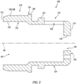
- the seal land 108 of FIG. 3 includes a land mount 116 and a (e.g., tubular) land base 118.
- the land mount 116 projects axially along the rotational axis 46 out from the land base 118 to the land second side 114.
- the land mount 116 extends radially between and to an inner side 120 of the land mount 116 and an outer side 122 of the land mount 116.
- the land mount 116 of FIG. 3 includes a (e.g., tubular) mount sidewall 124 and a (e.g., annular) mount endwall 126.
- the mount sidewall 124 of FIG. 3 is disposed at the mount outer side 122.
- the mount sidewall 124 extends axially along the rotational axis 46 from the land base 118 to the mount endwall 126.
- the mount sidewall 124 includes one or more ports 128 (one visible in FIG.
- the mount endwall 126 is disposed at the land second side 114.
- the mount endwall 126 is connected to the mount sidewall 124, and projects radially inward to the mount inner side 120.
- the mount endwall 126 includes a mounting aperture 130 that extends axially through the mount endwall 126.
- the land base 118 of FIG. 3 includes a (e.g., tubular) base sidewall 132 and a base locator 134 (e.g., an annular shoulder).
- the base sidewall 132 and, thus, the land base 118 project axially along the rotational axis 46 out from the land mount 116 to the land first side 112.
- the base sidewall 132 extends radially between and to an inner side 136 of the base sidewall 132 and an outer side 138 of the base sidewall 132.
- the base locator 134 is connected to the base sidewall 132 at, for example, an axial interface between the land base 118 and the land mount 116.
- the base locator 134 projects radially out from the base sidewall 132 and its outer side 138 to a distal end 140 of the base locator 134.
- the seal land 108 of FIG. 3 is configured with a land bore 142.
- This land bore 142 is radially bounded by the base sidewall 132 and the mount sidewall 124.
- the land bore 142 projects axially along the rotational axis 46 into the seal land 108 from the land first side 112 to the mount endwall 126.
- the land bore 142 is fluidly coupled with the ports 128 (one visible in FIG. 3 ).
- the seal land 108 of FIG. 3 and its components 116 and 118 are configured together as a monolithic body, which is discrete from the impeller rotor 32 and/or the shaft 34 (see FIG. 1 ).
- the seal land 108 may be cast, machined, additive manufactured and/or otherwise formed as a single, unitary body.
- the seal land 108 is constructed from or otherwise includes seal land material. This seal land material may be different than the impeller rotor material.
- the seal land material for example, may be a relatively dense, hard and/or abrasion resistant material such as, but not limited to, steel (e.g., stainless steel).
- steel e.g., stainless steel
- the seal element 110 extends axially along the rotational axis 46 between and to a first side 144 of the seal element 110 and a second side 146 of the seal element 110.
- the seal element 110 extends (e.g., completely) circumferentially around the rotational axis 46 providing the seal element 110 with a full-hoop (e.g., annular) body.
- the seal element 110 extends radially between an inner side 148 of the seal element 110 and an outer side 150 of the seal element 110.
- the seal element 110 may be configured as a (e.g., annular) lip seal.
- the seal element 110 of FIG. 4 for example, includes a (e.g., annular) seal base 152 and a (e.g., tubular) seal leg 154; e.g., a flange.
- the seal base 152 of FIG. 4 includes an outer leg 156 and an inner leg 158.
- the outer leg 156 is disposed at the element outer side 150.
- the outer leg 156 extends axially along the rotational axis 46 between and to (or about) the element first side 144 and the element second side 146.
- the inner leg 158 is disposed at the element first side 144, and is connected to (e.g., formed integral with) the outer leg 156.
- the inner leg 158 projects radially inwards from outer leg 156 to a first end 160 of the seal leg 154.
- the seal base 152 may have an L-shaped sectional geometry when viewed, for example, in a plane parallel with and/or coincident with the rotational axis 46; e.g., the plane of FIG. 4 .
- the seal leg 154 of FIG. 4 includes a (e.g., tubular) leg base 162 and a (e.g., annular) leg rim 164; e.g., a knife edge seal protrusion.
- the leg base 162 is disposed at the element inner side 148, and is connected to (e.g., formed integral with) and cantilevered from the inner leg 158.
- the leg base 162 extends axially along the rotational axis 46 between and to (or about) the element first side 144 and the element second side 146. More particularly, the leg base 162 of FIG. 4 projects axially out from the inner leg 158 and the seal leg first end 160 to a second end 166 of the seal leg 154 at the element second side 146.
- the leg rim 164 is disposed at (or about) the seal leg second end 166, and is connected to (e.g., formed integral with) the leg base 162.
- the leg rim 164 projects radially inward from the leg base 162 to a distal end tip 168; e.g., a pointed, annular edge.
- the seal element 110 may also include a biasing element 170 such as, but not limited to, a gator spring.
- the biasing element 170 of FIG. 4 extends circumferentially about and radially engages (e.g., contacts) the seal leg 154.
- the biasing element 170 of FIG. 4 for example, is seated in a (e.g., annular) backside groove 172 in the seal leg 154 proximate the element second end 146.
- This biasing element 170 is configured to bias (e.g., push) the seal leg 154 and, thus, the leg rim 164 radially inwards.
- the seal land 108 is mated with the impeller rotor 32.
- the land mount 116 for example, is inserted into the structure bore 92 (see FIG. 2 ).
- the mount sidewall 124 may radially engage (e.g., contact) or be in close proximity to the vane array structure 76.
- the mount endwall 126 may axially engage (e.g., contact, abut against) an annular shoulder 174 of the impeller rotor 32.
- An end portion 176 of the shaft 34 may project axially through the hub bore 84 (see FIG. 2 ) and the mounting aperture 130 (see FIG. 3 ), and into the land bore 142.
- a coupler 178 (e.g., a nut) may be mated with the shaft end portion 176 such that (A) the mount endwall 126 is captured and clamped axially between the coupler 178 and the rotor hub 72, and (B) the rotor hub 72 is captured and clamped axially between the mount endwall 126 and an annular shoulder 180 of the shaft 34.
- the shaft 34 may thereby (e.g., axially) secure (e.g., mechanically fasten) the impeller rotor 32 and the seal land 108 together.
- At least one fastener 182 may also be inserted into apertures (e.g., notches, recesses, etc.) in the mount endwall 126 and the rotor hub 72.
- the fastener 182 may thereby rotationally fix the impeller rotor 32 and the seal land 108 together.
- These assembled components 32, 34 and 108 form a rotating assembly for the deaerator 22, where the seal land 108 is generally located to the first side 64 of the impeller rotor 32 and the shaft 34 is generally located to the second side 66 of the impeller rotor 32.
- the impeller rotor 32 (e.g., the rotor shroud 74 and/or the vane array structure 76) and the seal land 108 are arranged in the rotor cavity 38.
- the impeller rotor 32 (e.g., the rotor hub 72) and the shaft 34 are seated within a bore 184 of the static structure 30.
- the shaft 34 may be rotatably supported within the static structure 30 by at least one bearing 186; e.g., a journal bearing.
- the inlet passages 100 are fluidly coupled with the fluid inlet passage 40.
- the liquid outlet passages 104 are fluidly coupled with the liquid outlet passage 42 through the outlet 106.
- the gas outlet passages 102 are fluidly coupled with the gas outlet passage 44 through the ports 128 (one visible in FIG. 1 ) and the land bore 142.
- the seal element 110 is arranged within the rotor cavity 38 adjacent the seal land 108.
- the seal base 152 for example, is attached to the static structure 30.
- the seal base 152 of FIG. 1 may be press-fit into a notch in the static structure 30.
- the seal leg 154 axially overlaps and radially engages an outer surface 188 of the seal land 108.
- the biasing element 170 biases the seal leg 154 against the seal land 108.
- the tip 168 may thereby sealingly engage (e.g., radially contact) the outer surface 188.
- the seal land 108 may be constructed from the relatively dense, durable and/or abrasion resistant seal land material as described above, the outer surface 188 may be susceptible to less wear than if the seal land 108 was made from a lightweight material such as the impeller rotor material.
- the impeller rotor 32 and/or the shaft 34 may be constructed from relative light weight materials, an overall rotating mass of the rotor assembly may be reduced.
- a ring seal element 190 (e.g., an O-ring) may be arranged between the vane array structure 76 and the land mount 116. This ring seal element 190 may form a sealed interface with and between the impeller rotor 32 and the seal land 108.
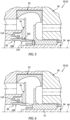
- the seal land 108 may engage the impeller rotor 32 through an interference fit 192.
- This interference fit 192 may provide a sealed interface between the components 76 and 116, which may replace (or be included in addition to) the ring seal element 190 of FIG. 1 for example.
- At least (or only) the seal land 108 and the rotor hub 72 may be formed together as a monolithic body.
- the vane array structure 76 may be attached to the monolithic body through, for example, an interference fit and/or various other types of mechanical fastening and/or bonding techniques.
- At least (or only) the seal land 108 and the shaft 34 may be formed together as a monolithic body.
- the impeller rotor 32 may be attached to the monolithic body through, for example, an interference fit and/or various other types of mechanical fastening and/or bonding techniques.
- the seal land 108 and the impeller rotor 32 may be formed together as a monolithic body.
- the seal land 108 may be substantially constructed from the impeller rotor material.
- the land base 118 may be provided with a hard coating 194 to form the outer surface 188.
- This hard coating 194 is configured to engage with (e.g., radially contact) the seal element 110.
- the hard coating 194 is configured from the seal land material described above and, thus, may provide the land base 118 with a wear resistant buffer.
- the turbine engine assembly 20 is described above as forming the deaerator 22.
- the present disclosure is not limited to such an exemplary arrangement.
- the impeller rotor 32 may alternatively be configured as a pump impeller rotor for a fluid pump; e.g., a lubricant pump, etc.
- the turbine engine assembly 20 may be included in various types of turbine engines.
- the turbine engine assembly 20, for example, may be included in a geared turbine engine where a gear train connects one or more shafts to one or more rotors in a fan section, a compressor section and/or any other engine section.
- the turbine engine assembly 20 may be included in a turbine engine configured without a gear train; e.g., a direct drive engine.
- the turbine engine assembly 20 may be included in a geared or non-geared turbine engine configured with a single spool, with two spools, or with more than two spools.
- the turbine engine may be configured as a turbofan engine, a turbojet engine, a turboshaft engine, a turboprop engine, a propfan engine, a pusher fan engine, an auxiliary power unit (APU) or any other type of turbine engine.
- the present disclosure therefore is not limited to any particular types or configurations of turbine engines.
- the present disclosure is also not limited to turbine engine applications.
- the assembly 20 / deaerator 22 may be configured to separate or otherwise pump fluids for other types of rotational equipment.
Landscapes
- Engineering & Computer Science (AREA)
- Mechanical Engineering (AREA)
- General Engineering & Computer Science (AREA)
- Chemical & Material Sciences (AREA)
- Combustion & Propulsion (AREA)
- Chemical Kinetics & Catalysis (AREA)
- Structures Of Non-Positive Displacement Pumps (AREA)
Abstract
Description
- This disclosure relates generally to rotational equipment and, more particularly, to a rotational equipment device with an impeller.
- Rotational equipment such as a gas turbine engine may include a deaerator for separating a fluid into its liquid and gas components. Various types and configurations of deaerators are known in the art. While these known deaerators have various benefits, there is still room in the art for improvement. For example, there is a need for a light-weight, wear resistant rotor assembly for a deaerator.
- According to an aspect of the present disclosure, an assembly is provided for a turbine engine. This turbine engine assembly includes an impeller rotor, a seal land and a lip seal. The impeller rotor is configured to rotate about a rotational axis. The impeller rotor is configured from or otherwise includes impeller rotor material. The seal land extends axially along and circumferentially about the rotational axis. The seal land is mechanically attached to and rotatable with the impeller rotor. The seal land is configured from or otherwise includes seal land material that is different than the impeller rotor material. The lip seal radially engages the seal land.
- According to another aspect of the present disclosure, another assembly is provided for a turbine engine. This turbine engine assembly includes an impeller rotor, a seal land and a lip seal. The impeller rotor is configured to rotate about a rotational axis. The impeller rotor is configured from or otherwise includes impeller rotor material. The seal land is rotatable with and projects axially along the rotational axis out from the impeller rotor. The seal land is configured from or otherwise includes seal land material that is different than the impeller rotor material. The lip seal radially engages the impeller rotor material.
- According to still another aspect of the present disclosure, another assembly is provided for a turbine engine. This turbine engine assembly includes a deaerator impeller rotor, a seal land and a stationary seal element. The deaerator impeller rotor is configured to rotate about a rotational axis. The deaerator impeller rotor is configured from or otherwise includes impeller rotor material. The seal land extends axially along and circumferentially about the rotational axis. The seal land is mechanically attached to and rotatable with the deaerator impeller rotor. The seal land is configured from or otherwise includes seal land material that is different than the impeller rotor material. The stationary seal element radially contacts the seal land.
- The seal land may include a base and a hard coating on the base. The base may be formed integrally with the impeller rotor. The hard coating may be configured from or otherwise include the seal land material.
- The seal land may project into a bore of and may be mechanically attached to the impeller rotor.
- The impeller rotor material may be configured from or otherwise include aluminum.
- The seal land material may be configured from or otherwise include steel.
- The impeller rotor may be configured as a deaerator impeller rotor.
- The lip seal may include a seal base and a seal leg. The seal leg may be axially cantilevered from the seal base. The seal leg may include a tip that radially contacts an outer surface of the seal land.
- The lip seal may also include a biasing element extending circumferentially about and radially engaging the seal leg. The biasing element may be configured to bias the seal leg radially inward against the outer surface of the seal land.
- The assembly may include a ring seal element configured to form a sealed interface with and between the impeller rotor and the seal land.
- The seal land may engage the impeller rotor through an interference fit.
- A rotor bore may extend axially along the rotational axis into the impeller rotor. The seal land may include a mount that projects axially along the rotational axis into the rotor bore. The mount may be mechanically attached to the impeller rotor.
- The mount may be axially clamped to the impeller rotor.
- A fastener may rotationally fix the mount to the impeller rotor.
- The assembly may also include a shaft mechanically attached to and rotatable with the impeller rotor.
- The shaft may be configured from or otherwise include shaft material that is different than the seal land material.
- The impeller rotor may extend axially along the rotational axis between a first side of the impeller rotor and a second side of the impeller rotor. The seal land may be arranged to the first side of the impeller rotor. The shaft may be arranged to the second side of the impeller rotor.
- At least the seal land and the shaft may be formed together as a monolithic body.
- The assembly may also include a static structure and a bearing rotatably supporting the shaft within the static structure. The lip seal may be fixedly secured to the static structure.
- The present disclosure may include any one or more of the individual features disclosed above and/or below alone or in any combination thereof.
- The foregoing features and the operation of the invention will become more apparent in light of the following description and the accompanying drawings.
-
-
FIG. 1 is a side sectional illustration of a portion of an assembly for a turbine engine. -
FIG. 2 is a side sectional illustration of an impeller rotor. -
FIG. 3 is a side sectional illustration of a seal land. -
FIG. 4 is a partial side sectional illustration of a seal element. -
FIGS. 5-8 are side sectional illustrations of the turbine engine assembly configured with various different component configurations. -
FIG. 1 illustrates an assembly 20 for a gas turbine engine. This turbine engine assembly 20 ofFIG. 1 forms a deaerator 22 for the turbine engine. This deaerator 22 is configured to separate afluid flow 24 with a liquid component and a gas component substantially into a separateliquid component flow 26 and a separategas component flow 28. The deaerator 22 may therefore also be referred to as a liquid-gas separator; e.g., a lubricant-air separator (also referred to as a de-oiler) where the liquid component is or otherwise includes lubricant (e.g., oil) and where the gas component is or otherwise includes air. The assembly 20 / the deaerator 22 ofFIG. 1 includes astatic structure 30, adeaerator impeller rotor 32 and ashaft 34. The deaerator 22 ofFIG. 1 also includes aseal assembly 36. - The
static structure 30 may be configured as a dedicated housing for thedeaerator components static structure 30 may alternatively be configured to support and/or house one or more other components of the turbine engine in addition to housing thedeaerator components static structure 30 ofFIG. 1 includes animpeller rotor cavity 38, afluid inlet passage 40, aliquid outlet passage 42 and agas outlet passage 44. - The
rotor cavity 38 extends radially out from a rotational axis 46 (e.g., a centerline) of the deaerator 22 within thestatic structure 30 to anouter side 48 of therotor cavity 38. Therotor cavity 38 extends (e.g., completely) circumferentially around therotational axis 46. Therotor cavity 38 extends axially along therotational axis 46 within thestatic structure 30 between and to afirst side 50 of therotor cavity 38 and asecond side 52 of therotor cavity 38. - The
fluid inlet passage 40 extends axially along therotational axis 46 within and/or into thestatic structure 30 to therotor cavity 38. An outlet of thefluid inlet passage 40 is fluidly coupled with therotor cavity 38. Thefluid inlet passage 40 is located to the rotor cavitysecond side 52. Acenterline 54 of thefluid inlet passage 40 ofFIG. 1 (e.g., at the outlet of the fluid inlet passage 40) is radially offset from therotational axis 46 by aradial distance 56. While the fluidinlet passage centerline 54 is shown inFIG. 1 as parallel with therotational axis 46, the present disclosure is not limited to such an exemplary arrangement. For example, in other embodiments, the fluidinlet passage centerline 54 and, thus, thefluid inlet passage 40 may be angularly offset from therotational axis 46 and/or angularly offset from the rotor cavitysecond side 52 by an acute or an obtuse angle. - The
liquid outlet passage 42 extends axially along therotational axis 46 within and/or into thestatic structure 30 to therotor cavity 38. An inlet to theliquid outlet passage 42 is fluidly coupled with therotor cavity 38. Theliquid outlet passage 42 is located to the rotor cavityfirst side 50. Acenterline 58 of theliquid outlet passage 42 ofFIG. 1 (e.g., at the inlet to the liquid outlet passage 42) is radially offset from therotational axis 46 by aradial distance 60. Thisdistance 60 may be greater than thedistance 56. While the liquidoutlet passage centerline 58 is shown inFIG. 1 as parallel with therotational axis 46, the present disclosure is not limited to such an exemplary arrangement. For example, in other embodiments, the liquidoutlet passage centerline 58 and, thus, theliquid outlet passage 42 may be angularly offset from therotational axis 46 and/or angularly offset from the rotor cavityfirst side 50 by an acute or an obtuse angle. - The
gas outlet passage 44 extends axially along therotational axis 46 within and/or into thestatic structure 30 to therotor cavity 38. An inlet to thegas outlet passage 44 is fluidly coupled with therotor cavity 38. Thegas outlet passage 44 is located to the rotor cavityfirst side 50. A centerline 62 of thegas outlet passage 44 ofFIG. 1 may be aligned (e.g., coaxial) with therotational axis 46. With this arrangement, thegas outlet passage 44 is positioned radially inward of theliquid outlet passage 42, and thefluid inlet passage 40 is generally aligned radially between theoutlet passages - The
impeller rotor 32 ofFIG. 2 is rotatable about therotational axis 46. Theimpeller rotor 32 extends axially along therotational axis 46 between and to afirst side 64 of theimpeller rotor 32 and asecond side 66 of theimpeller rotor 32. Theimpeller rotor 32 extends (e.g., completely) circumferentially around therotational axis 46 providing theimpeller rotor 32 with a full-hoop body. Theimpeller rotor 32 extends radially between and to aninner side 68 of theimpeller rotor 32 and anouter side 70 of theimpeller rotor 32. Theimpeller rotor 32 ofFIG. 2 includes an innerimpeller rotor hub 72, an outerimpeller rotor shroud 74 and avane array structure 76. - The
rotor hub 72 extends axially along therotational axis 46 between and to the rotorsecond side 66 and afirst side 78 of therotor hub 72. The hubfirst side 78 ofFIG. 2 axially offset (e.g., recessed) from the rotorfirst side 64. The hubfirst side 78 ofFIG. 2 , for example, is located axially at (e.g., on, adjacent or proximate) asecond side 80 of thevane array structure 76. Therotor hub 72 extends (e.g., completely) circumferentially around therotational axis 46 providing therotor hub 72 with a tubular body. Therotor hub 72 extends radially between and to the rotorinner side 68 and anouter side 82 of therotor hub 72. Therotor hub 72 forms a hub bore 84 within theimpeller rotor 32. This hub bore 84 projects axially along therotational axis 46 into theimpeller rotor 32 from the rotorsecond side 66. - The
rotor shroud 74 extends axially along therotational axis 46 between and to the rotorfirst side 64 and asecond side 86 of therotor shroud 74. The shroudsecond side 86 ofFIG. 2 is axially offset (e.g., recessed) from the rotorsecond side 66. A portion of therotor shroud 74 at the shroudsecond side 86 may axially overlap a portion of therotor hub 72 at the hubfirst side 78. Therotor shroud 74 extends (e.g., completely) circumferentially around therotational axis 46 providing therotor shroud 74 with a tubular body. Therotor shroud 74 extends radially between and to aninner side 87 of therotor shroud 74 to the rotorouter side 70. - The
vane array structure 76 extends axially along therotational axis 46 between and to afirst side 90 of thevane array structure 76 and thesecond side 80 of thevane array structure 76. Thevane array structure 76 extends (e.g., completely) circumferentially around therotational axis 46 providing thevane array structure 76 with a full-hoop body. Thevane array structure 76 is arranged radially between and is connected to (e.g., formed integral with) therotor hub 72 and therotor shroud 74. Aninner side 88 of thevane array structure 76 forms a structure bore 92 (or a counter bore to the hub bore 84) within theimpeller rotor 32. This structure bore 92 projects axially along therotational axis 46 into theimpeller rotor 32 from the structurefirst side 90 to, for example, the hub bore 84. - The
vane array structure 76 ofFIG. 2 includes a plurality ofimpeller rotor vanes 94, an axialfirst structure sidewall 96 and an axialsecond structure sidewall 98. The rotor vanes 94 are arranged circumferentially about therotational axis 46 in an array. This annular array ofrotor vanes 94 is located radially between therotor hub 72 and therotor shroud 74, and axially adjacent and/or radially along the structure sidewalls 96 and 98. Each of therotor vanes 94 ofFIG. 2 , for example, extends radially between and to therotor hub 72 and therotor shroud 74. An inner portion of each of therotor vanes 94 extend axially along therotational axis 46 between and to thefirst structure sidewall 96 and thesecond structure sidewall 98. Thefirst structure sidewall 96 is disposed towards thefirst side 90 of thevane array structure 76. Thesecond structure sidewall 98 is disposed towards thesecond side 80 of thevane array structure 76. - The
impeller rotor 32 ofFIG. 2 includes a plurality ofinlet passages 100, a plurality ofgas outlet passages 102 and a plurality ofliquid outlet passages 104. Theinlet passages 100 are located towards thesecond side 80 of thevane array structure 76. Each of theseinlet passages 100 is disposed circumferentially between a circumferentially neighboring (e.g., adjacent) pair of the rotor vanes 94. Each of theinlet passages 100 projects axially along therotational axis 46 into theimpeller rotor 32 and itsvane array structure 76 from thesecond side 80 of thevane array structure 76 to (or about) thesecond structure sidewall 98. - Each of the
gas outlet passages 102 is disposed circumferentially between a circumferentially neighboring (e.g., adjacent) pair of the rotor vanes 94. Each of thegas outlet passages 102 is fluidly coupled with a respective one of theinlet passages 100, and follows a respective (e.g., curved) trajectory within the vane array structure 76 (axially between and radially along thestructure walls 96 and 98) to a respective outlet at theinner side 88 of thevane array structure 76. The trajectory of each respectivegas outlet passage 102 ofFIG. 2 turns around a radial outer tip of thesecond structure wall 98. Eachgas outlet passage 102 fluidly couples therespective inlet passage 100 to the structure bore 92. - Each of the
liquid outlet passages 104 is disposed circumferentially between a circumferentially neighboring (e.g., adjacent) pair of the rotor vanes 94. Each of theliquid outlet passages 104 is fluidly coupled with a respective one of theinlet passages 100, and follows a respective (e.g., curved) trajectory within thevane array structure 76 to an outlet 106 (e.g., an annular outlet passage) at thefirst side 90 of thevane array structure 76. The trajectory of each respectiveliquid outlet passage 104 ofFIG. 2 turns around a radial outer tip of thefirst structure wall 96. Eachliquid outlet passage 104 fluidly couples therespective inlet passage 100 to theoutlet 106. - With the foregoing arrangement, each respective set of
passages impeller rotor 32. An inner leg of the forked pathway extends to the structure bore 92. An outer leg of the forked pathway extends to theoutlet 106. - The
impeller rotor 32 ofFIG. 2 and itscomponents impeller rotor 32, for example, may be cast, machined, additive manufactured and/or otherwise formed as a single, unitary body. By contract, a non-unitary body is formed from a plurality of discretely formed parts which are assembled together after formation. Theimpeller rotor 32 is constructed from or otherwise includes impeller rotor material. This impeller rotor material may be a relatively light-weight metal such as, but not limited to, aluminum (Al) or aluminum alloy. The present disclosure, however, is not limited to the foregoing exemplary impeller rotor materials, nor to monolithic impeller rotor configurations. - Referring to
FIG. 1 , theshaft 34 extends axially along and is rotatable about therotational axis 46. Theshaft 34 is constructed from or otherwise includes shaft material. This shaft material be the same as or different than the impeller rotor material. The shaft material, for example, may be a relatively light-weight metal such as, but not limited to, aluminum (Al) or aluminum alloy. Alternatively, the shaft material may be a denser and/or harder metal such as, but not limited to, steel (e.g., stainless steel). The present disclosure, however, is not limited to the foregoing exemplary shaft materials. - The
seal assembly 36 includes an impeller rotor seal land 108 (e.g., a sleave) and astationary seal element 110. Referring toFIG. 3 , theseal land 108 extends axially along therotational axis 46 between and to afirst side 112 of theseal land 108 and asecond side 114 of theseal land 108. Theseal land 108 extends (e.g., completely) circumferentially around therotational axis 46 providing theseal land 108 with a full-hoop (e.g., tubular) body. Theseal land 108 ofFIG. 3 includes aland mount 116 and a (e.g., tubular)land base 118. - The
land mount 116 projects axially along therotational axis 46 out from theland base 118 to the landsecond side 114. Theland mount 116 extends radially between and to aninner side 120 of theland mount 116 and anouter side 122 of theland mount 116. Theland mount 116 ofFIG. 3 includes a (e.g., tubular)mount sidewall 124 and a (e.g., annular)mount endwall 126. Themount sidewall 124 ofFIG. 3 is disposed at the mountouter side 122. Themount sidewall 124 extends axially along therotational axis 46 from theland base 118 to themount endwall 126. Themount sidewall 124 includes one or more ports 128 (one visible inFIG. 3 ) (e.g., apertures such as through-holes) arranged circumferentially about therotational axis 46, where eachport 128 extends radially through themount sidewall 124. The mount endwall 126 is disposed at the landsecond side 114. The mount endwall 126 is connected to themount sidewall 124, and projects radially inward to the mountinner side 120. The mount endwall 126 includes a mountingaperture 130 that extends axially through themount endwall 126. - The
land base 118 ofFIG. 3 includes a (e.g., tubular)base sidewall 132 and a base locator 134 (e.g., an annular shoulder). Thebase sidewall 132 and, thus, theland base 118 project axially along therotational axis 46 out from theland mount 116 to the landfirst side 112. Thebase sidewall 132 extends radially between and to aninner side 136 of thebase sidewall 132 and an outer side 138 of thebase sidewall 132. Thebase locator 134 is connected to thebase sidewall 132 at, for example, an axial interface between theland base 118 and theland mount 116. Thebase locator 134 projects radially out from thebase sidewall 132 and its outer side 138 to adistal end 140 of thebase locator 134. - The
seal land 108 ofFIG. 3 is configured with aland bore 142. This land bore 142 is radially bounded by thebase sidewall 132 and themount sidewall 124. The land bore 142 projects axially along therotational axis 46 into theseal land 108 from the landfirst side 112 to themount endwall 126. The land bore 142 is fluidly coupled with the ports 128 (one visible inFIG. 3 ). - The
seal land 108 ofFIG. 3 and itscomponents impeller rotor 32 and/or the shaft 34 (seeFIG. 1 ). Theseal land 108, for example, may be cast, machined, additive manufactured and/or otherwise formed as a single, unitary body. Theseal land 108 is constructed from or otherwise includes seal land material. This seal land material may be different than the impeller rotor material. The seal land material, for example, may be a relatively dense, hard and/or abrasion resistant material such as, but not limited to, steel (e.g., stainless steel). The present disclosure, however, is not limited to the foregoing exemplary seal land materials, nor to monolithic seal land configurations. - Referring to
FIG. 4 , theseal element 110 extends axially along therotational axis 46 between and to afirst side 144 of theseal element 110 and asecond side 146 of theseal element 110. Theseal element 110 extends (e.g., completely) circumferentially around therotational axis 46 providing theseal element 110 with a full-hoop (e.g., annular) body. Theseal element 110 extends radially between aninner side 148 of theseal element 110 and anouter side 150 of theseal element 110. - The
seal element 110 may be configured as a (e.g., annular) lip seal. Theseal element 110 ofFIG. 4 , for example, includes a (e.g., annular)seal base 152 and a (e.g., tubular)seal leg 154; e.g., a flange. Theseal base 152 ofFIG. 4 includes anouter leg 156 and aninner leg 158. Theouter leg 156 is disposed at the elementouter side 150. Theouter leg 156 extends axially along therotational axis 46 between and to (or about) the elementfirst side 144 and the elementsecond side 146. Theinner leg 158 is disposed at the elementfirst side 144, and is connected to (e.g., formed integral with) theouter leg 156. Theinner leg 158 projects radially inwards fromouter leg 156 to afirst end 160 of theseal leg 154. With this arrangement, theseal base 152 may have an L-shaped sectional geometry when viewed, for example, in a plane parallel with and/or coincident with therotational axis 46; e.g., the plane ofFIG. 4 . - The
seal leg 154 ofFIG. 4 includes a (e.g., tubular)leg base 162 and a (e.g., annular)leg rim 164; e.g., a knife edge seal protrusion. Theleg base 162 is disposed at the elementinner side 148, and is connected to (e.g., formed integral with) and cantilevered from theinner leg 158. Theleg base 162 extends axially along therotational axis 46 between and to (or about) the elementfirst side 144 and the elementsecond side 146. More particularly, theleg base 162 ofFIG. 4 projects axially out from theinner leg 158 and the seal legfirst end 160 to asecond end 166 of theseal leg 154 at the elementsecond side 146. Theleg rim 164 is disposed at (or about) the seal legsecond end 166, and is connected to (e.g., formed integral with) theleg base 162. The leg rim 164 projects radially inward from theleg base 162 to adistal end tip 168; e.g., a pointed, annular edge. - The
seal element 110 may also include abiasing element 170 such as, but not limited to, a gator spring. The biasingelement 170 ofFIG. 4 extends circumferentially about and radially engages (e.g., contacts) theseal leg 154. The biasingelement 170 ofFIG. 4 , for example, is seated in a (e.g., annular)backside groove 172 in theseal leg 154 proximate the elementsecond end 146. This biasingelement 170 is configured to bias (e.g., push) theseal leg 154 and, thus, theleg rim 164 radially inwards. - Referring to
FIG. 1 , theseal land 108 is mated with theimpeller rotor 32. Theland mount 116, for example, is inserted into the structure bore 92 (seeFIG. 2 ). Themount sidewall 124 may radially engage (e.g., contact) or be in close proximity to thevane array structure 76. The mount endwall 126 may axially engage (e.g., contact, abut against) anannular shoulder 174 of theimpeller rotor 32. Anend portion 176 of theshaft 34 may project axially through the hub bore 84 (seeFIG. 2 ) and the mounting aperture 130 (seeFIG. 3 ), and into the land bore 142. A coupler 178 (e.g., a nut) may be mated with theshaft end portion 176 such that (A) themount endwall 126 is captured and clamped axially between thecoupler 178 and therotor hub 72, and (B) therotor hub 72 is captured and clamped axially between themount endwall 126 and anannular shoulder 180 of theshaft 34. Theshaft 34 may thereby (e.g., axially) secure (e.g., mechanically fasten) theimpeller rotor 32 and theseal land 108 together. At least one fastener 182 (e.g., a pin) may also be inserted into apertures (e.g., notches, recesses, etc.) in themount endwall 126 and therotor hub 72. Thefastener 182 may thereby rotationally fix theimpeller rotor 32 and theseal land 108 together. These assembledcomponents seal land 108 is generally located to thefirst side 64 of theimpeller rotor 32 and theshaft 34 is generally located to thesecond side 66 of theimpeller rotor 32. - The impeller rotor 32 (e.g., the
rotor shroud 74 and/or the vane array structure 76) and theseal land 108 are arranged in therotor cavity 38. The impeller rotor 32 (e.g., the rotor hub 72) and theshaft 34 are seated within abore 184 of thestatic structure 30. Theshaft 34 may be rotatably supported within thestatic structure 30 by at least onebearing 186; e.g., a journal bearing. Theinlet passages 100 are fluidly coupled with thefluid inlet passage 40. Theliquid outlet passages 104 are fluidly coupled with theliquid outlet passage 42 through theoutlet 106. Thegas outlet passages 102 are fluidly coupled with thegas outlet passage 44 through the ports 128 (one visible inFIG. 1 ) and the land bore 142. - To reduce or prevent fluid leakage between the
liquid outlet passage 42 and thegas outlet passage 44, theseal element 110 is arranged within therotor cavity 38 adjacent theseal land 108. Theseal base 152, for example, is attached to thestatic structure 30. Theseal base 152 ofFIG. 1 , for example, may be press-fit into a notch in thestatic structure 30. Theseal leg 154 axially overlaps and radially engages anouter surface 188 of theseal land 108. The biasingelement 170 biases theseal leg 154 against theseal land 108. Thetip 168 may thereby sealingly engage (e.g., radially contact) theouter surface 188. Since theseal land 108 may be constructed from the relatively dense, durable and/or abrasion resistant seal land material as described above, theouter surface 188 may be susceptible to less wear than if theseal land 108 was made from a lightweight material such as the impeller rotor material. By contrast, since theimpeller rotor 32 and/or theshaft 34 may be constructed from relative light weight materials, an overall rotating mass of the rotor assembly may be reduced. - In some embodiments, referring to
FIG. 1 , a ring seal element 190 (e.g., an O-ring) may be arranged between thevane array structure 76 and theland mount 116. Thisring seal element 190 may form a sealed interface with and between theimpeller rotor 32 and theseal land 108. - In some embodiments, referring to
FIG. 5 , theseal land 108 may engage theimpeller rotor 32 through aninterference fit 192. This interference fit 192 may provide a sealed interface between thecomponents ring seal element 190 ofFIG. 1 for example. - In some embodiments, referring to
FIG. 6 , at least (or only) theseal land 108 and therotor hub 72 may be formed together as a monolithic body. In such embodiments, thevane array structure 76 may be attached to the monolithic body through, for example, an interference fit and/or various other types of mechanical fastening and/or bonding techniques. - In some embodiments, referring to
FIG. 7 , at least (or only) theseal land 108 and theshaft 34 may be formed together as a monolithic body. In such embodiments, theimpeller rotor 32 may be attached to the monolithic body through, for example, an interference fit and/or various other types of mechanical fastening and/or bonding techniques. - In some embodiments, referring to
FIG. 8 , at least (or only) theseal land 108 and theimpeller rotor 32 may be formed together as a monolithic body. In such embodiments, theseal land 108 may be substantially constructed from the impeller rotor material. However, theland base 118 may be provided with a hard coating 194 to form theouter surface 188. This hard coating 194 is configured to engage with (e.g., radially contact) theseal element 110. The hard coating 194 is configured from the seal land material described above and, thus, may provide theland base 118 with a wear resistant buffer. - The turbine engine assembly 20 is described above as forming the deaerator 22. The present disclosure, however, is not limited to such an exemplary arrangement. In other examples, for example, the
impeller rotor 32 may alternatively be configured as a pump impeller rotor for a fluid pump; e.g., a lubricant pump, etc. - The turbine engine assembly 20 may be included in various types of turbine engines. The turbine engine assembly 20, for example, may be included in a geared turbine engine where a gear train connects one or more shafts to one or more rotors in a fan section, a compressor section and/or any other engine section. Alternatively, the turbine engine assembly 20 may be included in a turbine engine configured without a gear train; e.g., a direct drive engine. The turbine engine assembly 20 may be included in a geared or non-geared turbine engine configured with a single spool, with two spools, or with more than two spools. The turbine engine may be configured as a turbofan engine, a turbojet engine, a turboshaft engine, a turboprop engine, a propfan engine, a pusher fan engine, an auxiliary power unit (APU) or any other type of turbine engine. The present disclosure therefore is not limited to any particular types or configurations of turbine engines. The present disclosure is also not limited to turbine engine applications. For example, the assembly 20 / deaerator 22 may be configured to separate or otherwise pump fluids for other types of rotational equipment.
- While various embodiments of the present disclosure have been described, it will be apparent to those of ordinary skill in the art that many more embodiments and implementations are possible within the scope of the disclosure. For example, the present disclosure as described herein includes several aspects and embodiments that include particular features. Although these features may be described individually, it is within the scope of the present disclosure that some or all of these features may be combined with any one of the aspects and remain within the scope of the disclosure. Accordingly, the present disclosure is not to be restricted except in light of the attached claims and their equivalents.
Claims (15)
- An assembly (20) for a turbine engine, comprising:an impeller rotor (32) configured to rotate about a rotational axis (46), the impeller rotor (32) comprising impeller rotor material;a seal land (108) extending axially along and circumferentially about the rotational axis (46), the seal land (108) mechanically attached to and rotatable with the impeller rotor (32), and the seal land (108) comprising seal land material that is different than the impeller rotor material; anda lip seal (110) radially engaging the seal land (108).
- The assembly (20) of claim 1, wherein the impeller rotor material comprises aluminum and/or, wherein the seal land material comprises steel.
- The assembly (20) of claim 1 or 2, wherein the impeller rotor (32) is configured as a deaerator impeller rotor (32).
- The assembly (20) of any preceding claim, wherein:the lip seal (110) includes a seal base (152) and a seal leg (154);the seal leg (154) is axially cantilevered from the seal base (152); andthe seal leg (154) comprises a tip (168) that radially contacts an outer surface (188) of the seal land (108).
- The assembly (20) of claim 4, wherein:the lip seal (110) further includes a biasing element (170) extending circumferentially about and radially engaging the seal leg (154); andthe biasing element (170) is configured to bias the seal leg (154) radially inward against the outer surface (188) of the seal land (108).
- The assembly (20) of any preceding claim, further comprising a ring seal element (190) configured to form a sealed interface with and between the impeller rotor (32) and the seal land (108).
- The assembly (20) of any preceding claim, wherein the seal land (108) engages the impeller rotor (32) through an interference fit (192).
- The assembly (20) of any preceding claim, wherein:a rotor bore (92) extends axially along the rotational axis (46) into the impeller rotor (32); andthe seal land (108) comprises a mount (116) that projects axially along the rotational axis (46) into the rotor bore (92), and the mount (116) is mechanically attached to the impeller rotor (32),optionally wherein either:the mount (116) is axially clamped to the impeller rotor (32); ora fastener (182) rotationally fixes the mount (116) to the impeller rotor (32).
- The assembly (20) of any preceding claim, further comprising a shaft (34) mechanically attached to and rotatable with the impeller rotor (32), wherein the shaft (34) optionally comprises shaft material that is different than the seal land material.
- The assembly (20) of claim 9, wherein the impeller rotor (32) extends axially along the rotational axis (46) between a first side (64) of the impeller rotor (32) and a second side (66) of the impeller rotor (32);the seal land (108) is arranged to the first side (64) of the impeller rotor (32); andthe shaft (34) is arranged to the second side (66) of the impeller rotor (32).
- The assembly (20) of claim 9 or 10, wherein at least the seal land (108) and the shaft (34) are formed together as a monolithic body.
- The assembly (20) of any of claims 9 to 11, further comprising:a static structure (30); anda bearing (186) rotatably supporting the shaft (34) within the static structure (30);wherein the lip seal (110) is fixedly secured to the static structure (30).
- An assembly (20) for a turbine engine, comprising:an impeller rotor (32) configured to rotate about a rotational axis (46), the impeller rotor (32) comprising impeller rotor material;a seal land (108) rotatable with and projecting axially along the rotational axis (46) out from the impeller rotor (32), the seal land (108) comprising seal land material that is different than the impeller rotor material; anda lip seal (110) radially engaging the impeller rotor material.
- The assembly (20) of claim 13, wherein the seal land (108) comprises a base (118) and a hard coating (194) on the base (118);the base (118) is formed integrally with the impeller rotor (32); andthe hard coating (194) comprises the seal land material;
and/orwherein the seal land (108) projects into a bore (92) of and is mechanically attached to the impeller rotor (32). - An assembly (20) for a turbine engine, comprising:a deaerator impeller rotor (32) configured to rotate about a rotational axis (46), the deaerator impeller rotor (32) comprising impeller rotor material;a seal land (108) extending axially along and circumferentially about the rotational axis (46), the seal land (108) mechanically attached to and rotatable with the deaerator impeller rotor (32), and the seal land (108) comprising seal land material that is different than the impeller rotor material; anda stationary seal element (110) radially contacting the seal land (108).
Applications Claiming Priority (1)
| Application Number | Priority Date | Filing Date | Title |
|---|---|---|---|
| US17/395,850 US11719243B2 (en) | 2021-08-06 | 2021-08-06 | Impeller rotor configured with wear resistant seal land |
Publications (1)
| Publication Number | Publication Date |
|---|---|
| EP4137219A1 true EP4137219A1 (en) | 2023-02-22 |
Family
ID=83149049
Family Applications (1)
| Application Number | Title | Priority Date | Filing Date |
|---|---|---|---|
| EP22188262.4A Pending EP4137219A1 (en) | 2021-08-06 | 2022-08-02 | Impeller rotor configured with seal land of different material than the rotor |
Country Status (3)
| Country | Link |
|---|---|
| US (1) | US11719243B2 (en) |
| EP (1) | EP4137219A1 (en) |
| CA (1) | CA3169388A1 (en) |
Families Citing this family (5)
| Publication number | Priority date | Publication date | Assignee | Title |
|---|---|---|---|---|
| US20250116245A1 (en) * | 2023-10-06 | 2025-04-10 | Pratt & Whitney Canada Corp. | Deaerator impeller rotor with gear rotor |
| US12535183B2 (en) * | 2024-01-19 | 2026-01-27 | Pratt & Whitney Canada Corp. | Fluid flow metering device for aircraft shaft(s) |
| US20260126046A1 (en) * | 2024-11-01 | 2026-05-07 | Pratt & Whitney Canada Corp. | Impeller rotor seal runner with anti-rotation feature |
| US12510082B1 (en) * | 2024-11-01 | 2025-12-30 | Pratt & Whitney Canada Corp. | Impeller rotor seal runner with divergent guide surface |
| US12480424B1 (en) * | 2025-02-21 | 2025-11-25 | Pratt & Whitney Canada Corp. | Active de-aerator for aircraft power plant |
Citations (3)
| Publication number | Priority date | Publication date | Assignee | Title |
|---|---|---|---|---|
| US20160097293A1 (en) * | 2014-10-01 | 2016-04-07 | Electro-Motive Diesel, Inc. | Compressor seal assembly for a turbocharger |
| GB2532197A (en) * | 2014-11-04 | 2016-05-18 | Rolls Royce Plc | A sealing assembly |
| FR3090035A1 (en) * | 2018-12-18 | 2020-06-19 | Safran Aircraft Engines | DEVICE FOR DECOOLING AND SEALING A LUBRICATION ENCLOSURE OF A TURBOMACHINE |
Family Cites Families (14)
| Publication number | Priority date | Publication date | Assignee | Title |
|---|---|---|---|---|
| US2296701A (en) | 1939-01-21 | 1942-09-22 | Bristol Aeroplane Co Ltd | Gas turbine |
| AT304971B (en) * | 1968-08-02 | 1973-02-12 | Jenoe Szepesvary Dipl Ing | Seal designed as a radial or axial seal |
| FR2273458A5 (en) * | 1973-12-21 | 1975-12-26 | Paulstra Sa | |
| US4217120A (en) | 1977-10-20 | 1980-08-12 | Sundstrand Corporation | Air-oil separator for aircraft gearbox |
| US4569638A (en) | 1982-11-30 | 1986-02-11 | International Telephone And Telegraph Corporation | Pump with resiliently mounted impeller |
| US4798320A (en) * | 1985-09-20 | 1989-01-17 | Allied-Signal Inc. | Ceramic-metal brazed joint for turbochargers |
| US7252474B2 (en) | 2003-09-12 | 2007-08-07 | Mes International, Inc. | Sealing arrangement in a compressor |
| US7377110B2 (en) | 2004-03-31 | 2008-05-27 | United Technologies Corporation | Deoiler for a lubrication system |
| WO2006043556A1 (en) * | 2004-10-19 | 2006-04-27 | Komatsu Ltd. | Turbo machine, compressor impeller used for turbo machine, and method of manufacturing turbo machine |
| US8985277B2 (en) | 2012-07-31 | 2015-03-24 | United Technologies Corporation | Case with integral lubricant scavenge passage |
| US9464572B2 (en) | 2013-12-20 | 2016-10-11 | Pratt & Whitney Canada Corp. | Oil tank and scavenge pipe assembly of a gas turbine engine and method of delivering an oil and air mixture to same |
| EP3184864B1 (en) * | 2014-08-20 | 2019-01-30 | Nok Corporation | Sealing structure |
| GB201807266D0 (en) | 2018-05-03 | 2018-06-20 | Rolls Royce Plc | Oil tank |
| US11619237B2 (en) * | 2020-02-14 | 2023-04-04 | Raytheon Technologies Corporation | Carbon seal assembly |
-
2021
- 2021-08-06 US US17/395,850 patent/US11719243B2/en active Active
-
2022
- 2022-08-02 EP EP22188262.4A patent/EP4137219A1/en active Pending
- 2022-08-02 CA CA3169388A patent/CA3169388A1/en active Pending
Patent Citations (3)
| Publication number | Priority date | Publication date | Assignee | Title |
|---|---|---|---|---|
| US20160097293A1 (en) * | 2014-10-01 | 2016-04-07 | Electro-Motive Diesel, Inc. | Compressor seal assembly for a turbocharger |
| GB2532197A (en) * | 2014-11-04 | 2016-05-18 | Rolls Royce Plc | A sealing assembly |
| FR3090035A1 (en) * | 2018-12-18 | 2020-06-19 | Safran Aircraft Engines | DEVICE FOR DECOOLING AND SEALING A LUBRICATION ENCLOSURE OF A TURBOMACHINE |
Also Published As
| Publication number | Publication date |
|---|---|
| US20230044553A1 (en) | 2023-02-09 |
| US11719243B2 (en) | 2023-08-08 |
| CA3169388A1 (en) | 2023-02-06 |
Similar Documents
| Publication | Publication Date | Title |
|---|---|---|
| US11719243B2 (en) | Impeller rotor configured with wear resistant seal land | |
| EP3196517B1 (en) | Secondary seal device(s) with alignment tab(s) | |
| US8800133B2 (en) | Gas turbine systems involving rotor bayonet coverplates and tools for installing such coverplates | |
| EP3284983B1 (en) | Non-contact seal with monolithic/unitary carrier structure | |
| US4391565A (en) | Nozzle guide vane assemblies for turbomachines | |
| US10233762B2 (en) | Cooled seal assembly for arranging between a stator and a rotor | |
| US12510082B1 (en) | Impeller rotor seal runner with divergent guide surface | |
| US10641180B2 (en) | Hydrostatic non-contact seal with varied thickness beams | |
| EP3431836B1 (en) | Non-contact seal with non-straight spring beam(s) | |
| US11674406B2 (en) | Variable gap between impeller rotor and static structure | |
| EP3428489B1 (en) | Hydrostatic non-contact seal with seal carrier elimination | |
| US10731761B2 (en) | Hydrostatic non-contact seal with offset outer ring | |
| EP1509682B1 (en) | Increased wear-life mechanical face seal anti-rotation system | |
| US8517688B2 (en) | Rotor assembly for use in turbine engines and methods for assembling same | |
| RU2743065C2 (en) | Radial locking element for sealing of steam turbine rotor, corresponding unit and steam turbine | |
| US11578803B2 (en) | Cartridge seal assembly for rotational equipment | |
| EP3527801B1 (en) | Pressure balanced secondary seal | |
| JP2010127240A (en) | Fitting structure of impeller | |
| US12018567B2 (en) | Joint between gas turbine engine components with bonded fastener(s) | |
| EP4736980A1 (en) | Impeller rotor seal runner with anti-rotation feature | |
| WO2021035564A1 (en) | Baffle element, diffuser plate, and seal system incorporating a baffle element and a diffuser plate | |
| US12416248B2 (en) | Sleeve mounted onto a low-pressure shaft in a turbomachine |
Legal Events
| Date | Code | Title | Description |
|---|---|---|---|
| PUAI | Public reference made under article 153(3) epc to a published international application that has entered the european phase |
Free format text: ORIGINAL CODE: 0009012 |
|
| STAA | Information on the status of an ep patent application or granted ep patent |
Free format text: STATUS: THE APPLICATION HAS BEEN PUBLISHED |
|
| AK | Designated contracting states |
Kind code of ref document: A1 Designated state(s): AL AT BE BG CH CY CZ DE DK EE ES FI FR GB GR HR HU IE IS IT LI LT LU LV MC MK MT NL NO PL PT RO RS SE SI SK SM TR |
|
| STAA | Information on the status of an ep patent application or granted ep patent |
Free format text: STATUS: REQUEST FOR EXAMINATION WAS MADE |
|
| 17P | Request for examination filed |
Effective date: 20230807 |
|
| RBV | Designated contracting states (corrected) |
Designated state(s): AL AT BE BG CH CY CZ DE DK EE ES FI FR GB GR HR HU IE IS IT LI LT LU LV MC MK MT NL NO PL PT RO RS SE SI SK SM TR |