EP4137213A1 - Cadence measurement device and cadence measurement method - Google Patents
Cadence measurement device and cadence measurement method Download PDFInfo
- Publication number
- EP4137213A1 EP4137213A1 EP21799820.2A EP21799820A EP4137213A1 EP 4137213 A1 EP4137213 A1 EP 4137213A1 EP 21799820 A EP21799820 A EP 21799820A EP 4137213 A1 EP4137213 A1 EP 4137213A1
- Authority
- EP
- European Patent Office
- Prior art keywords
- waveform
- cadence
- myoelectric potential
- processing
- measurement device
- Prior art date
- Legal status (The legal status is an assumption and is not a legal conclusion. Google has not performed a legal analysis and makes no representation as to the accuracy of the status listed.)
- Granted
Links
Images





Classifications
-
- A—HUMAN NECESSITIES
- A63—SPORTS; GAMES; AMUSEMENTS
- A63B—APPARATUS FOR PHYSICAL TRAINING, GYMNASTICS, SWIMMING, CLIMBING, OR FENCING; BALL GAMES; TRAINING EQUIPMENT
- A63B24/00—Electric or electronic controls for exercising apparatus of preceding groups; Controlling or monitoring of exercises, sportive games, training or athletic performances
- A63B24/0062—Monitoring athletic performances, e.g. for determining the work of a user on an exercise apparatus, the completed jogging or cycling distance
-
- A—HUMAN NECESSITIES
- A61—MEDICAL OR VETERINARY SCIENCE; HYGIENE
- A61B—DIAGNOSIS; SURGERY; IDENTIFICATION
- A61B5/00—Measuring for diagnostic purposes; Identification of persons
- A61B5/24—Detecting, measuring or recording bioelectric or biomagnetic signals of the body or parts thereof
- A61B5/316—Modalities, i.e. specific diagnostic methods
- A61B5/389—Electromyography [EMG]
- A61B5/397—Analysis of electromyograms
-
- A—HUMAN NECESSITIES
- A61—MEDICAL OR VETERINARY SCIENCE; HYGIENE
- A61B—DIAGNOSIS; SURGERY; IDENTIFICATION
- A61B2503/00—Evaluating a particular growth phase or type of persons or animals
- A61B2503/10—Athletes
-
- A—HUMAN NECESSITIES
- A61—MEDICAL OR VETERINARY SCIENCE; HYGIENE
- A61B—DIAGNOSIS; SURGERY; IDENTIFICATION
- A61B2505/00—Evaluating, monitoring or diagnosing in the context of a particular type of medical care
- A61B2505/09—Rehabilitation or training
-
- A—HUMAN NECESSITIES
- A61—MEDICAL OR VETERINARY SCIENCE; HYGIENE
- A61B—DIAGNOSIS; SURGERY; IDENTIFICATION
- A61B5/00—Measuring for diagnostic purposes; Identification of persons
- A61B5/68—Arrangements of detecting, measuring or recording means, e.g. sensors, in relation to patient
- A61B5/6801—Arrangements of detecting, measuring or recording means, e.g. sensors, in relation to patient specially adapted to be attached to or worn on the body surface
- A61B5/6813—Specially adapted to be attached to a specific body part
- A61B5/6828—Leg
-
- A—HUMAN NECESSITIES
- A63—SPORTS; GAMES; AMUSEMENTS
- A63B—APPARATUS FOR PHYSICAL TRAINING, GYMNASTICS, SWIMMING, CLIMBING, OR FENCING; BALL GAMES; TRAINING EQUIPMENT
- A63B22/00—Exercising apparatus specially adapted for conditioning the cardio-vascular system, for training agility or co-ordination of movements
- A63B22/06—Exercising apparatus specially adapted for conditioning the cardio-vascular system, for training agility or co-ordination of movements with support elements performing a rotating cycling movement, i.e. a closed path movement
-
- A—HUMAN NECESSITIES
- A63—SPORTS; GAMES; AMUSEMENTS
- A63B—APPARATUS FOR PHYSICAL TRAINING, GYMNASTICS, SWIMMING, CLIMBING, OR FENCING; BALL GAMES; TRAINING EQUIPMENT
- A63B2220/00—Measuring of physical parameters relating to sporting activity
- A63B2220/17—Counting, e.g. counting periodical movements, revolutions or cycles, or including further data processing to determine distances or speed
-
- A—HUMAN NECESSITIES
- A63—SPORTS; GAMES; AMUSEMENTS
- A63B—APPARATUS FOR PHYSICAL TRAINING, GYMNASTICS, SWIMMING, CLIMBING, OR FENCING; BALL GAMES; TRAINING EQUIPMENT
- A63B2220/00—Measuring of physical parameters relating to sporting activity
- A63B2220/80—Special sensors, transducers or devices therefor
-
- A—HUMAN NECESSITIES
- A63—SPORTS; GAMES; AMUSEMENTS
- A63B—APPARATUS FOR PHYSICAL TRAINING, GYMNASTICS, SWIMMING, CLIMBING, OR FENCING; BALL GAMES; TRAINING EQUIPMENT
- A63B2220/00—Measuring of physical parameters relating to sporting activity
- A63B2220/80—Special sensors, transducers or devices therefor
- A63B2220/83—Special sensors, transducers or devices therefor characterised by the position of the sensor
- A63B2220/836—Sensors arranged on the body of the user
Definitions
- the present invention relates to a cadence measurement device and a cadence measurement method.
- the conventional bicycle-type exercise instrument uses a rotational speed sensor to measure cadence, so the structure is not simple.
- an object is to provide a cadence measurement device having a simple structure and to provide a cadence measurement method.
- a cadence measurement device in an embodiment of the present invention includes a myoelectric potential sensor attached to a leg portion of a living body, a waveform processing unit that performs waveform processing to obtain a myoelectric potential waveform from an output signal of the myoelectric potential sensor, and a cadence deriving unit that derives cadence according to the myoelectric potential waveform obtained by the waveform processing.
- Fig. 1 is a drawing indicating the structure of a cadence measurement device 100 in an embodiment.
- a smart phone 1 is also indicated.
- the cadence measurement device 100 is indicated more largely than the smart phone 10 to indicate the structure of the cadence measurement device 100 in detail.
- the actual cadence measurement device 100 is smaller and more lightweight than the smart phone 10.
- the cadence measurement device 100 includes a myoelectric potential sensor 110, a MCU (Micro Control Unit) 120, a communication unit 130, and a battery 140.
- the cadence measurement device 100 is attached to the thigh of the user who pedals a bicycle or bicycle-type exercise instrument by being stuck with, for example, a tape or the like. Then, the cadence measurement device 100 measures cadence.
- Cadence is a number of revolutions of the crank axis of the pedal per minute.
- the cadence measurement device 100 only needs to measure the myoelectric potential of the surface of the leg portion of the user with the myoelectric potential sensor 110.
- the cadence measurement device 100 is stuck so as to measure the myoelectric potential of the quadriceps muscle.
- the myoelectric potential sensor 110 has an analog amplifier circuit and a plurality of bioelectrodes stuck to the thigh of the user.
- the myoelectric potential sensor 110 amplifies a waveform signal, which represents a myoelectric potential detected in a hyperbolic lead method by using the plurality of bioelectrodes, with the analog amplifier circuit, and then outputs the waveform signal.
- the output of the myoelectric potential sensor 110 is an example of an output signal and is input into the MCU 120.
- the MCU 120 has a main control unit 121, a waveform processing unit 122, a cadence deriving unit 123, and a memory 124.
- the MCU 120 is realized by a microcomputer that includes a CPU (Central Processing Unit), a RAM (Random Access Memory), a ROM (Read Only Memory), and the like.
- the main control unit 121, waveform processing unit 122, cadence deriving unit 123 indicate the functions of programs executed by the MCU 120 as functional blocks.
- the memory 124 functionally represents a memory in the MCU 120.
- the main control unit 121 is a processing unit that controls the MCU 120 in a centralized manner, and executes processing other than processing executed by the waveform processing unit 122 and cadence deriving unit 123. Specifically, the main control unit 121 performs A/D (Analog to Digital) conversion processing on the output signal of the myoelectric potential sensor 110 to convert the output signal to a digital waveform signal and other processing, for example.
- A/D Analog to Digital
- the waveform processing unit 122 acquires data representing a myoelectric potential waveform by performing waveform processing on the output signal of the myoelectric potential sensor 110. Waveform processing performed by the waveform processing unit 122 will be described later by using Fig. 2 to Fig. 5 .
- the cadence deriving unit 123 derives cadence from the myoelectric potential waveform acquired by the waveform processing unit 122. Waveform processing performed by the cadence deriving unit 123 will be described later by using Fig.6 .
- the memory 124 is an example of a storage unit.
- the memory 124 stores programs and data needed by the MCU 120 to perform processing as well as other data, and also temporarily stores data to be used by the main control unit 121, waveform processing unit 122, and cadence deriving unit 123 in processing and the like.
- the communication unit 130 is a communication unit in BLE (Bluetooth Low Energy) (registered trademark) as an example, and performs data communication with the smart phone 10. Measurement results of the cadence measurement device 100 are transmitted to the smart phone 10 through the communication unit 130. Application programs for the cadence measurement device 100 are installed in the smart phone 10, as an example. The smart phone 10 displays or otherwise processes data that an application program has received from the cadence measurement device 100 on the display or the like of the smart phone 10.
- BLE Bluetooth Low Energy
- the communication unit 130 is a communication unit in BLE (Bluetooth Low Energy) (registered trademark) as an example, and performs data communication with the smart phone 10. Measurement results of the cadence measurement device 100 are transmitted to the smart phone 10 through the communication unit 130. Application programs for the cadence measurement device 100 are installed in the smart phone 10, as an example. The smart phone 10 displays or otherwise processes data that an application program has received from the cadence measurement device 100 on the display or the like of the smart phone 10.
- the battery 140 is a power source that supplies electric power to the myoelectric potential sensor 110, MCU 120, and communication unit 130.
- the battery 140 only needs to be a secondary battery, as an example.
- the battery 140 can be charged in a state in which the battery 140 is incorporated into the cadence measurement device 100 or is removed from the cadence measurement device 100.
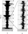
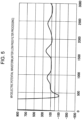
- Fig. 2 to Fig. 5 are drawings explaining waveform processing executed by the waveform processing unit 122.
- the horizontal axis indicates time and the vertical axis indicates amplitude.
- Fig. 2(A) indicates the waveform of a digital waveform signal created by the main control unit 121 through A/D conversion.
- Fig. 2(B) indicates part (segment for three seconds) in Fig. 2(A) by enlarging it in the horizontal-axis direction.
- the digital waveform signal indicated in Figs. 2(A) and (B) represents a myoelectric potential (EMG: ElectroMyoGraphy) but includes noise and the like as well.
- EMG ElectroMyoGraphy
- Fig. 3 indicates a component waveform after the waveform processing unit 122 has performed band-pass filter processing on the digital waveform signal indicated in Fig. 2(B) .
- Band-pass filter processing is filter processing (waveform processing) to pass only 20 Hz to 350 Hz, which are in a frequency band that the myoelectric potential waveform can take in the digital waveform signal, and remove components at lower than 20 Hz and components at higher than 350 Hz.
- Fig. 4 is a drawing indicating a myoelectric potential waveform obtained when the waveform processing unit 122 performs waveform processing on the component waveform indicated in Fig. 3 .
- the myoelectric potential waveform indicated in Fig. 4 is obtained.
- the myoelectric potential waveform is obtained by squaring the positive component and negative component of the component waveform indicated in Fig. 3 and taking a square root.
- Fig. 5 is a drawing indicating a myoelectric potential waveform that the waveform processing unit 122 obtains by performing low-pass filter processing on the myoelectric potential waveform indicated in Fig. 4 . It is said that the number of revolutions per minute when a human pedals a bicycle is 200 rpm (revolutions per minute), which is about 3.35 Hz, or less. Therefore, to extract components at 3.35 Hz or lower from the myoelectric potential waveform indicated in Fig. 4 , low-pass filter processing in which 3.35 Hz is used as the cut-off frequency is performed.
- Fig. 6 is a drawing explaining processing executed by the cadence deriving unit 123.
- the period T is a three-second period in the myoelectric potential waveform. Since it is thought that the period T includes a plurality of cycles during which the user pedals, the period T is set to three seconds as an example.
- the cadence deriving unit 123 obtains the average value A of amplitude data in the period T, and divides the period T into a plurality of cycles with the amplitude center of the myoelectric potential waveform in the period T taken as the average value A. In Fig. 6 , three cycles T1, T2, and T3 are included in the period T. There is a residual, which is shorter than one cycle, before cycle T1. The cadence deriving unit 123 obtains periods T1, T2, and T3.
- Fig. 7 is drawing indicating table data that relates cadence and the period (ms (milliseconds)) of one cycle to each other.
- the table data indicated in Fig. 7 is data that relates the period of one revolution (period of one cycle) of cadence used as the number of revolutions of the crank.
- Fig. 7 indicates the period (0.517 ms to 0.492 ms) of one cycle when cadence is 115 to 122 (revolutions/minute) .
- the cadence deriving unit 123 references the table data and derives the cadence for which the period of one cycle is closest to each of periods T1 to T3. As a result, it will be assumed as an example that the cadence deriving unit 123 has derived that cadence in period T1 is 120 (revolutions/minute), cadence in period T2 is 119 (revolutions/minute), and cadence in period T3 is 118 (revolutions/minute).
- the cadence measurement device 100 obtains cadence from the myoelectric potential waveform in the way described above.
- Fig. 8 is a flowchart indicating processing executed by the cadence measurement device 100.
- the cadence measurement device 100 has been stuck to the thigh of the user, the power supply of the cadence measurement device 100 is turned on, and the myoelectric potential sensor 110 is performing measurement of the myoelectric potential.
- Processing indicated in Fig. 8 is processing realized by the cadence measurement method in an embodiment.
- the main control unit 121 performs processing in which A/D conversion processing is performed on the output signal of the myoelectric potential sensor 110 to convert the output signal to a digital waveform signal (step S1). More specifically, as an example, the main control unit 121 creates a digital waveform signal by performing A/D conversion on the output signal of the myoelectric potential sensor 110 at a sampling cycle of 0.1 ms, and stores amplitude data of the digital waveform signal in the memory 124.
- the waveform processing unit 122 decides whether at least a predetermined number of amplitude data items of the digital waveform signal have been accumulated (step S2).
- at least the predetermined number of amplitude data items of the digital waveform signal refer to amplitude data items of the digital waveform signal for three seconds or more, as an example. This is because the periods of a plurality of cycles included in the period T for three seconds will be obtained later as in Fig. 6 .
- step S3 If the waveform processing unit 122 decides that at least the predetermined number of amplitude data items of the digital waveform signal have been accumulated (S2: YES), the waveform processing unit 122 performs band-pass filter processing on the digital waveform signals (step S3). Due to this, component waveforms after only 20 Hz to 350 Hz, which are in a frequency band that the myoelectric potential waveform can take, in the digital waveform signal has been passed are obtained as indicated in Fig. 3 . Incidentally, if the waveform processing unit 122 decides in step S2 that at least the predetermined number of amplitude data items of the digital waveform signal have not been accumulated (S2: NO), the waveform processing unit 122 returns the flow to step S1. This is because the waveform processing unit 122 waits for amplitude data to be further accumulated.
- the waveform processing unit 122 performs waveform processing to convert the amplitude of the component waveform to a signal waveform with root mean square (RMS) values (step S4). Due to this, a myoelectric potential waveform as indicated in Fig. 4 is obtained.
- RMS root mean square
- the waveform processing unit 122 performs low-pass filter processing on the myoelectric potential waveform (step S5). Due to this, out of the myoelectric potential waveforms obtained in step S4, components at 3.35 Hz or lower are extracted and a myoelectric potential waveform as indicated in Fig. 5 is obtained.
- the cadence deriving unit 123 calculates the average value A of amplitude data in the period T (step S6).
- the period T (see Fig. 6 ) is a period that includes at least the predetermined number of amplitude data items of the digital waveform signal, which have been obtained in step S2. That is, the period T is determined in step S2.
- the cadence deriving unit 123 measures the period of each cycle included in the period T (step S7).
- processing in step S7 is processing to measure a plurality of periods T1, T2, and T3 included in the period T, as described by using Fig. 6 .
- Measurement of periods T1, T2, and T3 only needs to be performed by obtaining an interval between sampling points, at which the amplitude data of the myoelectric potential waveform becomes the same as the average value A, in the direction of time. In this case, if there is no sampling point, at which a match with the amplitude data of the average value A is found, in the myoelectric potential waveform, interpolation or the like only needs to be performed for two sampling points between which the average value A is interposed.
- the cadence deriving unit 123 references the table data and derives the cadence for which the period of one cycle is closest to each of periods T1 to T3 (step S8).
- the main control unit 111 causes the communication unit 130 to transmit data representing cadence to the smart phone (step S9). Due to this, the smart phone 10 acquires the data representing cadence and displays the data on the display. The user can know the cadence by seeing the display of the smart phone 10.
- the main control unit 111 decides whether to terminate the processing (step S10).
- the time to terminate the processing is when a manipulation to terminate measurement processing by the cadence measurement device 100 is performed. If the main control unit 111 decides that the processing is not to be terminated (S10: NO), the main control unit 111 returns the flow to step S1. Also, if the main control unit 111 decides that the processing is to be terminated (S10: YES), the main control unit 111 terminates a series of processing.
- the cadence measurement device 100 obtains a myoelectric potential waveform by performing filter processing on an output signal representing the myoelectric potential detected by the myoelectric potential sensor 110 and performing waveform processing such as processing to covert to root mean square values, and derives cadence from cycles included in the myoelectric potential waveform.
- waveform processing such as processing to covert to root mean square values
- the cadence measurement device 100 having a simple structure and the cadence measurement method. Since the cadence measurement device 100 can be realized only with the myoelectric potential sensor 110, MCU 120, communication unit 130, and battery 140, the cadence measurement device 100 is very small and lightweight. Due to this, even when the user sticks the cadence measurement device 100 to the thigh with a tape or the like, the cadence measurement device 100 is less likely to drop off and cadence measurement can be stably continued for a long period of time. Also, even when the cadence measurement device 100 is stuck to the thigh of the user, there is very little feeling of discomfort, so the cadence measurement device 100 is superior in ease of attachment.
- the degree of fatigue of muscles of the user and the like may be inferred and may be displayed on the display together with cadence. Then, the user can quantitatively grasp the degree of fatigue of muscles of the user together with the cadence.
- the cadence deriving unit 123 measures the period of each cycle included in the period T and derives the cadence for which the period of one cycle is closest to each of periods T1 to T3.
- table data that relates cadence and the number of revolutions of the crank per second to each other may have been stored in the memory 124 instead of the table data indicated in Fig. 7 .
- the cadence closest to the reciprocal (number of revolutions of the crank per second) of the period of each cycle may be derived, the reciprocal being obtained by performing a Fourier transform on the myoelectric potential waveform indicated in Fig. 5 .
Landscapes
- Health & Medical Sciences (AREA)
- Life Sciences & Earth Sciences (AREA)
- General Health & Medical Sciences (AREA)
- Physical Education & Sports Medicine (AREA)
- Pathology (AREA)
- Animal Behavior & Ethology (AREA)
- Biomedical Technology (AREA)
- Heart & Thoracic Surgery (AREA)
- Medical Informatics (AREA)
- Molecular Biology (AREA)
- Surgery (AREA)
- Engineering & Computer Science (AREA)
- Physics & Mathematics (AREA)
- Public Health (AREA)
- Veterinary Medicine (AREA)
- Biophysics (AREA)
- Measurement And Recording Of Electrical Phenomena And Electrical Characteristics Of The Living Body (AREA)
- Measurement Of The Respiration, Hearing Ability, Form, And Blood Characteristics Of Living Organisms (AREA)
Abstract
Description
- The present invention relates to a cadence measurement device and a cadence measurement method.
- There has been a conventional bicycle-type exercise instrument in which a pedaling measurement unit attached to the bicycle-type exercise instrument has a rotational speed sensor and that measures cadence, which is the rotational speed of a crank portion, according to an output signal of the rotational speed sensor (see PTL 1, for example).
- PTL 1:
Japanese Unexamined Patent Application Publication No. 2018-110730 - Incidentally, the conventional bicycle-type exercise instrument uses a rotational speed sensor to measure cadence, so the structure is not simple.
- Therefore, an object is to provide a cadence measurement device having a simple structure and to provide a cadence measurement method.
- A cadence measurement device in an embodiment of the present invention includes a myoelectric potential sensor attached to a leg portion of a living body, a waveform processing unit that performs waveform processing to obtain a myoelectric potential waveform from an output signal of the myoelectric potential sensor, and a cadence deriving unit that derives cadence according to the myoelectric potential waveform obtained by the waveform processing.
- It is possible to provide a cadence measurement device having a simple structure and to provide a cadence measurement method.
-
- [
Fig. 1] Fig. 1 is a drawing indicating the structure of acadence measurement device 100 in an embodiment. - [
Fig. 2] Fig. 2 is a drawing explaining waveform processing executed by awaveform processing unit 122. - [
Fig. 3] Fig. 3 is a drawing explaining waveform processing executed by thewaveform processing unit 122. - [
Fig. 4] Fig. 4 is a drawing explaining waveform processing executed by thewaveform processing unit 122. - [
Fig. 5] Fig. 5 is a drawing explaining waveform processing executed by thewaveform processing unit 122. - [
Fig. 6] Fig. 6 is a drawing explaining processing executed by acadence deriving unit 123. - [
Fig. 7] Fig. 7 is a drawing indicating table data that relates cadence and the period of one cycle to each other. - [
Fig. 8] Fig. 8 is a flowchart indicating processing executed by thecadence measurement device 100. - Embodiments to which a cadence measurement device and a cadence measurement method in the present invention are applied will be described below.
-
Fig. 1 is a drawing indicating the structure of acadence measurement device 100 in an embodiment. InFig. 1 , a smart phone 1 is also indicated. InFig. 1 , thecadence measurement device 100 is indicated more largely than thesmart phone 10 to indicate the structure of thecadence measurement device 100 in detail. However, the actualcadence measurement device 100 is smaller and more lightweight than thesmart phone 10. - The
cadence measurement device 100 includes a myoelectricpotential sensor 110, a MCU (Micro Control Unit) 120, acommunication unit 130, and abattery 140. As an example, thecadence measurement device 100 is attached to the thigh of the user who pedals a bicycle or bicycle-type exercise instrument by being stuck with, for example, a tape or the like. Then, thecadence measurement device 100 measures cadence. Cadence is a number of revolutions of the crank axis of the pedal per minute. Thecadence measurement device 100 only needs to measure the myoelectric potential of the surface of the leg portion of the user with themyoelectric potential sensor 110. As an example, thecadence measurement device 100 is stuck so as to measure the myoelectric potential of the quadriceps muscle. - The myoelectric
potential sensor 110 has an analog amplifier circuit and a plurality of bioelectrodes stuck to the thigh of the user. The myoelectricpotential sensor 110 amplifies a waveform signal, which represents a myoelectric potential detected in a hyperbolic lead method by using the plurality of bioelectrodes, with the analog amplifier circuit, and then outputs the waveform signal. The output of the myoelectricpotential sensor 110 is an example of an output signal and is input into theMCU 120. - The MCU 120 has a
main control unit 121, awaveform processing unit 122, acadence deriving unit 123, and amemory 124. TheMCU 120 is realized by a microcomputer that includes a CPU (Central Processing Unit), a RAM (Random Access Memory), a ROM (Read Only Memory), and the like. Themain control unit 121,waveform processing unit 122,cadence deriving unit 123 indicate the functions of programs executed by the MCU 120 as functional blocks. Also, thememory 124 functionally represents a memory in theMCU 120. - The
main control unit 121 is a processing unit that controls theMCU 120 in a centralized manner, and executes processing other than processing executed by thewaveform processing unit 122 andcadence deriving unit 123. Specifically, themain control unit 121 performs A/D (Analog to Digital) conversion processing on the output signal of the myoelectricpotential sensor 110 to convert the output signal to a digital waveform signal and other processing, for example. - The
waveform processing unit 122 acquires data representing a myoelectric potential waveform by performing waveform processing on the output signal of the myoelectricpotential sensor 110. Waveform processing performed by thewaveform processing unit 122 will be described later by usingFig. 2 to Fig. 5 . - The cadence deriving
unit 123 derives cadence from the myoelectric potential waveform acquired by thewaveform processing unit 122. Waveform processing performed by thecadence deriving unit 123 will be described later by usingFig.6 . - The
memory 124 is an example of a storage unit. Thememory 124 stores programs and data needed by theMCU 120 to perform processing as well as other data, and also temporarily stores data to be used by themain control unit 121,waveform processing unit 122, andcadence deriving unit 123 in processing and the like. - The
communication unit 130 is a communication unit in BLE (Bluetooth Low Energy) (registered trademark) as an example, and performs data communication with thesmart phone 10. Measurement results of thecadence measurement device 100 are transmitted to thesmart phone 10 through thecommunication unit 130. Application programs for thecadence measurement device 100 are installed in thesmart phone 10, as an example. Thesmart phone 10 displays or otherwise processes data that an application program has received from thecadence measurement device 100 on the display or the like of thesmart phone 10. - The
battery 140 is a power source that supplies electric power to the myoelectricpotential sensor 110,MCU 120, andcommunication unit 130. Thebattery 140 only needs to be a secondary battery, as an example. Thebattery 140 can be charged in a state in which thebattery 140 is incorporated into thecadence measurement device 100 or is removed from thecadence measurement device 100. -
Fig. 2 to Fig. 5 are drawings explaining waveform processing executed by thewaveform processing unit 122. InFig. 2 to Fig. 5 , the horizontal axis indicates time and the vertical axis indicates amplitude.Fig. 2(A) indicates the waveform of a digital waveform signal created by themain control unit 121 through A/D conversion.Fig. 2(B) indicates part (segment for three seconds) inFig. 2(A) by enlarging it in the horizontal-axis direction. The digital waveform signal indicated inFigs. 2(A) and (B) represents a myoelectric potential (EMG: ElectroMyoGraphy) but includes noise and the like as well. -
Fig. 3 indicates a component waveform after thewaveform processing unit 122 has performed band-pass filter processing on the digital waveform signal indicated inFig. 2(B) . Band-pass filter processing is filter processing (waveform processing) to pass only 20 Hz to 350 Hz, which are in a frequency band that the myoelectric potential waveform can take in the digital waveform signal, and remove components at lower than 20 Hz and components at higher than 350 Hz. -
Fig. 4 is a drawing indicating a myoelectric potential waveform obtained when thewaveform processing unit 122 performs waveform processing on the component waveform indicated inFig. 3 . By performing waveform processing to convert the amplitude of the component waveform indicated inFig. 3 to a signal waveform with RMS (Root Mean Square) values, the myoelectric potential waveform indicated inFig. 4 is obtained. The myoelectric potential waveform is obtained by squaring the positive component and negative component of the component waveform indicated inFig. 3 and taking a square root. -
Fig. 5 is a drawing indicating a myoelectric potential waveform that thewaveform processing unit 122 obtains by performing low-pass filter processing on the myoelectric potential waveform indicated inFig. 4 . It is said that the number of revolutions per minute when a human pedals a bicycle is 200 rpm (revolutions per minute), which is about 3.35 Hz, or less. Therefore, to extract components at 3.35 Hz or lower from the myoelectric potential waveform indicated inFig. 4 , low-pass filter processing in which 3.35 Hz is used as the cut-off frequency is performed. -
Fig. 6 is a drawing explaining processing executed by thecadence deriving unit 123. InFig. 6 , the period T is a three-second period in the myoelectric potential waveform. Since it is thought that the period T includes a plurality of cycles during which the user pedals, the period T is set to three seconds as an example. - The
cadence deriving unit 123 obtains the average value A of amplitude data in the period T, and divides the period T into a plurality of cycles with the amplitude center of the myoelectric potential waveform in the period T taken as the average value A. InFig. 6 , three cycles T1, T2, and T3 are included in the period T. There is a residual, which is shorter than one cycle, before cycle T1. Thecadence deriving unit 123 obtains periods T1, T2, and T3. -
Fig. 7 is drawing indicating table data that relates cadence and the period (ms (milliseconds)) of one cycle to each other. The table data indicated inFig. 7 is data that relates the period of one revolution (period of one cycle) of cadence used as the number of revolutions of the crank. As an example,Fig. 7 indicates the period (0.517 ms to 0.492 ms) of one cycle when cadence is 115 to 122 (revolutions/minute) . - The
cadence deriving unit 123 references the table data and derives the cadence for which the period of one cycle is closest to each of periods T1 to T3. As a result, it will be assumed as an example that thecadence deriving unit 123 has derived that cadence in period T1 is 120 (revolutions/minute), cadence in period T2 is 119 (revolutions/minute), and cadence in period T3 is 118 (revolutions/minute). Thecadence measurement device 100 obtains cadence from the myoelectric potential waveform in the way described above. -
Fig. 8 is a flowchart indicating processing executed by thecadence measurement device 100. As a premise, it will be assumed that thecadence measurement device 100 has been stuck to the thigh of the user, the power supply of thecadence measurement device 100 is turned on, and the myoelectricpotential sensor 110 is performing measurement of the myoelectric potential. Processing indicated inFig. 8 is processing realized by the cadence measurement method in an embodiment. - The
main control unit 121 performs processing in which A/D conversion processing is performed on the output signal of the myoelectricpotential sensor 110 to convert the output signal to a digital waveform signal (step S1). More specifically, as an example, themain control unit 121 creates a digital waveform signal by performing A/D conversion on the output signal of the myoelectricpotential sensor 110 at a sampling cycle of 0.1 ms, and stores amplitude data of the digital waveform signal in thememory 124. - The
waveform processing unit 122 decides whether at least a predetermined number of amplitude data items of the digital waveform signal have been accumulated (step S2). Here, at least the predetermined number of amplitude data items of the digital waveform signal refer to amplitude data items of the digital waveform signal for three seconds or more, as an example. This is because the periods of a plurality of cycles included in the period T for three seconds will be obtained later as inFig. 6 . - If the
waveform processing unit 122 decides that at least the predetermined number of amplitude data items of the digital waveform signal have been accumulated (S2: YES), thewaveform processing unit 122 performs band-pass filter processing on the digital waveform signals (step S3). Due to this, component waveforms after only 20 Hz to 350 Hz, which are in a frequency band that the myoelectric potential waveform can take, in the digital waveform signal has been passed are obtained as indicated inFig. 3 . Incidentally, if thewaveform processing unit 122 decides in step S2 that at least the predetermined number of amplitude data items of the digital waveform signal have not been accumulated (S2: NO), thewaveform processing unit 122 returns the flow to step S1. This is because thewaveform processing unit 122 waits for amplitude data to be further accumulated. - The
waveform processing unit 122 performs waveform processing to convert the amplitude of the component waveform to a signal waveform with root mean square (RMS) values (step S4). Due to this, a myoelectric potential waveform as indicated inFig. 4 is obtained. - The
waveform processing unit 122 performs low-pass filter processing on the myoelectric potential waveform (step S5). Due to this, out of the myoelectric potential waveforms obtained in step S4, components at 3.35 Hz or lower are extracted and a myoelectric potential waveform as indicated inFig. 5 is obtained. - The
cadence deriving unit 123 calculates the average value A of amplitude data in the period T (step S6). The period T (seeFig. 6 ) is a period that includes at least the predetermined number of amplitude data items of the digital waveform signal, which have been obtained in step S2. That is, the period T is determined in step S2. - The
cadence deriving unit 123 measures the period of each cycle included in the period T (step S7). As an example, processing in step S7 is processing to measure a plurality of periods T1, T2, and T3 included in the period T, as described by usingFig. 6 . Measurement of periods T1, T2, and T3 only needs to be performed by obtaining an interval between sampling points, at which the amplitude data of the myoelectric potential waveform becomes the same as the average value A, in the direction of time. In this case, if there is no sampling point, at which a match with the amplitude data of the average value A is found, in the myoelectric potential waveform, interpolation or the like only needs to be performed for two sampling points between which the average value A is interposed. - The
cadence deriving unit 123 references the table data and derives the cadence for which the period of one cycle is closest to each of periods T1 to T3 (step S8). - The main control unit 111 causes the
communication unit 130 to transmit data representing cadence to the smart phone (step S9). Due to this, thesmart phone 10 acquires the data representing cadence and displays the data on the display. The user can know the cadence by seeing the display of thesmart phone 10. - The main control unit 111 decides whether to terminate the processing (step S10). The time to terminate the processing is when a manipulation to terminate measurement processing by the
cadence measurement device 100 is performed. If the main control unit 111 decides that the processing is not to be terminated (S10: NO), the main control unit 111 returns the flow to step S1. Also, if the main control unit 111 decides that the processing is to be terminated (S10: YES), the main control unit 111 terminates a series of processing. - As described above, the
cadence measurement device 100 obtains a myoelectric potential waveform by performing filter processing on an output signal representing the myoelectric potential detected by the myoelectricpotential sensor 110 and performing waveform processing such as processing to covert to root mean square values, and derives cadence from cycles included in the myoelectric potential waveform. In this case, there is no need to use a rotational speed sensor and there is also no need to use an acceleration sensor and the like, as in the past. Due to this, thecadence measurement device 100 can be realized with a very simple structure. - Therefore, it is possible to provide the
cadence measurement device 100 having a simple structure and the cadence measurement method. Since thecadence measurement device 100 can be realized only with the myoelectricpotential sensor 110,MCU 120,communication unit 130, andbattery 140, thecadence measurement device 100 is very small and lightweight. Due to this, even when the user sticks thecadence measurement device 100 to the thigh with a tape or the like, thecadence measurement device 100 is less likely to drop off and cadence measurement can be stably continued for a long period of time. Also, even when thecadence measurement device 100 is stuck to the thigh of the user, there is very little feeling of discomfort, so thecadence measurement device 100 is superior in ease of attachment. - Also, in processing performed by an application program in the
smart phone 10 after the myoelectric potential waveform measured by thecadence measurement device 100 is transmitted to thesmart phone 10, the degree of fatigue of muscles of the user and the like may be inferred and may be displayed on the display together with cadence. Then, the user can quantitatively grasp the degree of fatigue of muscles of the user together with the cadence. - Incidentally, an aspect has been described above in which the
cadence deriving unit 123 measures the period of each cycle included in the period T and derives the cadence for which the period of one cycle is closest to each of periods T1 to T3. However, table data that relates cadence and the number of revolutions of the crank per second to each other may have been stored in thememory 124 instead of the table data indicated inFig. 7 . Then, in the table data, the cadence closest to the reciprocal (number of revolutions of the crank per second) of the period of each cycle may be derived, the reciprocal being obtained by performing a Fourier transform on the myoelectric potential waveform indicated inFig. 5 . - So far, the cadence measurement device and cadence measurement method in exemplary embodiments in the present invention have been described. However, the present invention is not limited to specifically disclosed embodiments. Various variations and modifications are possible without departing from the scope of the claims.
- Incidentally, this international application claims priority based on
Japanese Patent Application No. 2020-082718 filed on May 8, 2020 -
- 100
- cadence measurement device
- 110
- myoelectric potential sensor
- 120
- MCU
- 122
- waveform processing unit
- 123
- cadence deriving unit
Claims (6)
- A cadence measurement device, comprising:a myoelectric potential sensor attached to a leg portion of a living body;a waveform processing unit that performs waveform processing to obtain a myoelectric potential waveform from an output signal of the myoelectric potential sensor; anda cadence deriving unit that derives cadence according to the myoelectric potential waveform obtained by the waveform processing.
- The cadence measurement device according to Claim 1, wherein the waveform processing unit obtains the myoelectric potential waveform from the output signal by performing, as the waveform processing, processing to covert the output signal of the myoelectric potential sensor to a signal waveform with a root mean square value.
- The cadence measurement device according to Claim 2, wherein the waveform processing unit obtains the myoelectric potential waveform from the output signal by performing, as the waveform processing, processing to extract a component waveform, which is a waveform of a frequency component included in the myoelectric potential waveform of the living body, from the output signal of the myoelectric potential sensor and processing to convert the component waveform to a signal waveform with a root mean square value.
- The cadence measurement device according to any one of Claims 1 to 3, wherein when an average value of an amplitude in a plurality of cycles of the myoelectric potential waveform is taken as an amplitude center and the myoelectric potential waveform is divided into each cycle according to the amplitude center, the cadence deriving unit derives the cadence according to a period of the each cycle.
- The cadence measurement device according to Claim 4, further comprising a storage unit that stores table data that relates a number of crank revolutions and a period of one cycle, wherein
the cadence deriving unit derives, as the cadence, the number of crank revolutions that corresponds, in the table data, to the period of the each cycle. - A cadence measurement method comprising:performing waveform processing to obtain a myoelectric potential waveform from an output signal of a myoelectric potential sensor attached to a leg portion of a living body; andderiving cadence according to the myoelectric potential waveform obtained by the waveform processing.
Applications Claiming Priority (2)
| Application Number | Priority Date | Filing Date | Title |
|---|---|---|---|
| JP2020082718 | 2020-05-08 | ||
| PCT/JP2021/008180 WO2021225025A1 (en) | 2020-05-08 | 2021-03-03 | Cadence measurement device and cadence measurement method |
Publications (3)
| Publication Number | Publication Date |
|---|---|
| EP4137213A1 true EP4137213A1 (en) | 2023-02-22 |
| EP4137213A4 EP4137213A4 (en) | 2024-04-17 |
| EP4137213B1 EP4137213B1 (en) | 2025-08-27 |
Family
ID=78467997
Family Applications (1)
| Application Number | Title | Priority Date | Filing Date |
|---|---|---|---|
| EP21799820.2A Active EP4137213B1 (en) | 2020-05-08 | 2021-03-03 | Cadence measurement device and cadence measurement method |
Country Status (4)
| Country | Link |
|---|---|
| US (1) | US20230047257A1 (en) |
| EP (1) | EP4137213B1 (en) |
| JP (1) | JP7488891B2 (en) |
| WO (1) | WO2021225025A1 (en) |
Family Cites Families (9)
| Publication number | Priority date | Publication date | Assignee | Title |
|---|---|---|---|---|
| JP2007268016A (en) | 2006-03-31 | 2007-10-18 | Casio Comput Co Ltd | Biological information measuring apparatus and biological information measuring system |
| JP5783723B2 (en) * | 2007-12-21 | 2015-09-24 | フォールブルック インテレクチュアル プロパティー カンパニー エルエルシー | Automatic transmission and method thereof |
| US9005129B2 (en) * | 2012-06-22 | 2015-04-14 | Fitbit, Inc. | Wearable heart rate monitor |
| US9579048B2 (en) * | 2012-07-30 | 2017-02-28 | Treefrog Developments, Inc | Activity monitoring system with haptic feedback |
| WO2015128226A1 (en) | 2014-02-26 | 2015-09-03 | Koninklijke Philips N.V. | Device for measuring a cycling cadence |
| US10206598B2 (en) * | 2014-12-03 | 2019-02-19 | Panasonic Intellectual Property Management Co., Ltd. | Muscular fatigue determination apparatus, method for determining muscular fatigue, and recording medium |
| JP6879745B2 (en) | 2017-01-12 | 2021-06-02 | ブリヂストンサイクル株式会社 | Muscle activity state analysis system, muscle activity state analysis method and program |
| US20190073605A1 (en) * | 2017-02-27 | 2019-03-07 | Andrew Jay KELLER | Systems and methods for real-time neural command classification and task execution |
| JP6623432B1 (en) | 2018-11-27 | 2019-12-25 | 广州力寄采礦設備有限公司 | Safe cutting equipment |
-
2021
- 2021-03-03 JP JP2022519898A patent/JP7488891B2/en active Active
- 2021-03-03 EP EP21799820.2A patent/EP4137213B1/en active Active
- 2021-03-03 WO PCT/JP2021/008180 patent/WO2021225025A1/en not_active Ceased
-
2022
- 2022-10-26 US US17/974,167 patent/US20230047257A1/en not_active Abandoned
Also Published As
| Publication number | Publication date |
|---|---|
| US20230047257A1 (en) | 2023-02-16 |
| JPWO2021225025A1 (en) | 2021-11-11 |
| JP7488891B2 (en) | 2024-05-22 |
| WO2021225025A1 (en) | 2021-11-11 |
| EP4137213B1 (en) | 2025-08-27 |
| EP4137213A4 (en) | 2024-04-17 |
Similar Documents
| Publication | Publication Date | Title |
|---|---|---|
| Veltink et al. | Detection of static and dynamic activities using uniaxial accelerometers | |
| Yoon et al. | Improvement of dynamic respiration monitoring through sensor fusion of accelerometer and gyro-sensor | |
| CN113223662B (en) | A method and system for limb intelligent rehabilitation training | |
| JP2023521655A (en) | Exercise data processing method and exercise monitoring system | |
| EP2943753B1 (en) | Cadence detection based on inertial harmonics | |
| US10524676B2 (en) | Apparatus and method for determining a health parameter of a subject | |
| CN103099611B (en) | Interference suppression system for sphygmomanometer measurement and interference suppression method thereof | |
| JP2016107093A (en) | Muscle fatigue determination device, muscle fatigue determination method, and muscle fatigue determination program | |
| CN105233487A (en) | Body-building assisting system and method | |
| CN105181998A (en) | Method for detecting SEMG and motion locus of arm in shooting mode | |
| KR102039236B1 (en) | Indicator Derivatives, Wearables, and Mobile Devices | |
| EP4137213B1 (en) | Cadence measurement device and cadence measurement method | |
| JP2003038469A (en) | Motion function measuring device and motion function measuring system | |
| JP6259301B2 (en) | Moving motion analysis apparatus, method and system, and program | |
| JP2011250945A (en) | Gait analysis method, system, and apparatus | |
| LeMoyne et al. | Implementation of an iPod application as a wearable and wireless accelerometer system for identifying quantified disparity of hemiplegic gait | |
| JPWO2023127008A5 (en) | DYNAMIC BALANCE ESTIMATION DEVICE, DYNAMIC BALANCE ESTIMATION SYSTEM, DYNAMIC BALANCE ESTIMATION METHOD, AND PROGRAM | |
| Lemoyne et al. | Implementation of a smartphone as a wireless accelerometer platform for quantifying hemiplegic gait disparity in a functionally autonomous context | |
| JP6378492B2 (en) | Moving motion analysis apparatus and program | |
| US20160235358A1 (en) | Intelligent interactive-rhythmic neuromuscular rehabilitation system | |
| Lemoyne et al. | Wireless accelerometer system for quantifying disparity of hemiplegic gait using the frequency domain | |
| CN112115813A (en) | Human body electromyographic signal labeling method and device and computing equipment | |
| CN207590681U (en) | A kind of portable muscular fatigue degree detection device based on electronics epidermis | |
| WO2014177763A1 (en) | Heart rate and activity monitor arrangement and a method for using the same | |
| JP6378491B2 (en) | Moving motion analysis apparatus, method and system, and program |
Legal Events
| Date | Code | Title | Description |
|---|---|---|---|
| STAA | Information on the status of an ep patent application or granted ep patent |
Free format text: STATUS: THE INTERNATIONAL PUBLICATION HAS BEEN MADE |
|
| PUAI | Public reference made under article 153(3) epc to a published international application that has entered the european phase |
Free format text: ORIGINAL CODE: 0009012 |
|
| STAA | Information on the status of an ep patent application or granted ep patent |
Free format text: STATUS: REQUEST FOR EXAMINATION WAS MADE |
|
| 17P | Request for examination filed |
Effective date: 20221027 |
|
| AK | Designated contracting states |
Kind code of ref document: A1 Designated state(s): AL AT BE BG CH CY CZ DE DK EE ES FI FR GB GR HR HU IE IS IT LI LT LU LV MC MK MT NL NO PL PT RO RS SE SI SK SM TR |
|
| DAV | Request for validation of the european patent (deleted) | ||
| DAX | Request for extension of the european patent (deleted) | ||
| A4 | Supplementary search report drawn up and despatched |
Effective date: 20240319 |
|
| RIC1 | Information provided on ipc code assigned before grant |
Ipc: A61B 5/389 20210101ALI20240313BHEP Ipc: A63B 71/06 20060101ALI20240313BHEP Ipc: A63B 69/16 20060101ALI20240313BHEP Ipc: A63B 22/06 20060101AFI20240313BHEP |
|
| STAA | Information on the status of an ep patent application or granted ep patent |
Free format text: STATUS: EXAMINATION IS IN PROGRESS |
|
| 17Q | First examination report despatched |
Effective date: 20241011 |
|
| GRAP | Despatch of communication of intention to grant a patent |
Free format text: ORIGINAL CODE: EPIDOSNIGR1 |
|
| STAA | Information on the status of an ep patent application or granted ep patent |
Free format text: STATUS: GRANT OF PATENT IS INTENDED |
|
| INTG | Intention to grant announced |
Effective date: 20250415 |
|
| GRAS | Grant fee paid |
Free format text: ORIGINAL CODE: EPIDOSNIGR3 |
|
| GRAA | (expected) grant |
Free format text: ORIGINAL CODE: 0009210 |
|
| STAA | Information on the status of an ep patent application or granted ep patent |
Free format text: STATUS: THE PATENT HAS BEEN GRANTED |
|
| AK | Designated contracting states |
Kind code of ref document: B1 Designated state(s): AL AT BE BG CH CY CZ DE DK EE ES FI FR GB GR HR HU IE IS IT LI LT LU LV MC MK MT NL NO PL PT RO RS SE SI SK SM TR |
|
| REG | Reference to a national code |
Ref country code: CH Ref legal event code: EP |
|
| REG | Reference to a national code |
Ref country code: DE Ref legal event code: R096 Ref document number: 602021037295 Country of ref document: DE |
|
| REG | Reference to a national code |
Ref country code: IE Ref legal event code: FG4D |
|
| REG | Reference to a national code |
Ref country code: NL Ref legal event code: MP Effective date: 20250827 |
|
| PG25 | Lapsed in a contracting state [announced via postgrant information from national office to epo] |
Ref country code: IS Free format text: LAPSE BECAUSE OF FAILURE TO SUBMIT A TRANSLATION OF THE DESCRIPTION OR TO PAY THE FEE WITHIN THE PRESCRIBED TIME-LIMIT Effective date: 20251227 |
|
| PG25 | Lapsed in a contracting state [announced via postgrant information from national office to epo] |
Ref country code: NO Free format text: LAPSE BECAUSE OF FAILURE TO SUBMIT A TRANSLATION OF THE DESCRIPTION OR TO PAY THE FEE WITHIN THE PRESCRIBED TIME-LIMIT Effective date: 20251127 |
|
| REG | Reference to a national code |
Ref country code: LT Ref legal event code: MG9D |
|
| PG25 | Lapsed in a contracting state [announced via postgrant information from national office to epo] |
Ref country code: PT Free format text: LAPSE BECAUSE OF FAILURE TO SUBMIT A TRANSLATION OF THE DESCRIPTION OR TO PAY THE FEE WITHIN THE PRESCRIBED TIME-LIMIT Effective date: 20251229 |
|
| PG25 | Lapsed in a contracting state [announced via postgrant information from national office to epo] |
Ref country code: FI Free format text: LAPSE BECAUSE OF FAILURE TO SUBMIT A TRANSLATION OF THE DESCRIPTION OR TO PAY THE FEE WITHIN THE PRESCRIBED TIME-LIMIT Effective date: 20250827 |
|
| PG25 | Lapsed in a contracting state [announced via postgrant information from national office to epo] |
Ref country code: NL Free format text: LAPSE BECAUSE OF FAILURE TO SUBMIT A TRANSLATION OF THE DESCRIPTION OR TO PAY THE FEE WITHIN THE PRESCRIBED TIME-LIMIT Effective date: 20250827 Ref country code: HR Free format text: LAPSE BECAUSE OF FAILURE TO SUBMIT A TRANSLATION OF THE DESCRIPTION OR TO PAY THE FEE WITHIN THE PRESCRIBED TIME-LIMIT Effective date: 20250827 |
|
| PG25 | Lapsed in a contracting state [announced via postgrant information from national office to epo] |
Ref country code: GR Free format text: LAPSE BECAUSE OF FAILURE TO SUBMIT A TRANSLATION OF THE DESCRIPTION OR TO PAY THE FEE WITHIN THE PRESCRIBED TIME-LIMIT Effective date: 20251128 |
|
| PG25 | Lapsed in a contracting state [announced via postgrant information from national office to epo] |
Ref country code: SE Free format text: LAPSE BECAUSE OF FAILURE TO SUBMIT A TRANSLATION OF THE DESCRIPTION OR TO PAY THE FEE WITHIN THE PRESCRIBED TIME-LIMIT Effective date: 20250827 |
|
| PG25 | Lapsed in a contracting state [announced via postgrant information from national office to epo] |
Ref country code: LV Free format text: LAPSE BECAUSE OF FAILURE TO SUBMIT A TRANSLATION OF THE DESCRIPTION OR TO PAY THE FEE WITHIN THE PRESCRIBED TIME-LIMIT Effective date: 20250827 |
|
| PG25 | Lapsed in a contracting state [announced via postgrant information from national office to epo] |
Ref country code: BG Free format text: LAPSE BECAUSE OF FAILURE TO SUBMIT A TRANSLATION OF THE DESCRIPTION OR TO PAY THE FEE WITHIN THE PRESCRIBED TIME-LIMIT Effective date: 20250827 Ref country code: PL Free format text: LAPSE BECAUSE OF FAILURE TO SUBMIT A TRANSLATION OF THE DESCRIPTION OR TO PAY THE FEE WITHIN THE PRESCRIBED TIME-LIMIT Effective date: 20250827 |
|
| PG25 | Lapsed in a contracting state [announced via postgrant information from national office to epo] |
Ref country code: RS Free format text: LAPSE BECAUSE OF FAILURE TO SUBMIT A TRANSLATION OF THE DESCRIPTION OR TO PAY THE FEE WITHIN THE PRESCRIBED TIME-LIMIT Effective date: 20251127 |
|
| PG25 | Lapsed in a contracting state [announced via postgrant information from national office to epo] |
Ref country code: ES Free format text: LAPSE BECAUSE OF FAILURE TO SUBMIT A TRANSLATION OF THE DESCRIPTION OR TO PAY THE FEE WITHIN THE PRESCRIBED TIME-LIMIT Effective date: 20250827 |
|
| REG | Reference to a national code |
Ref country code: AT Ref legal event code: MK05 Ref document number: 1829363 Country of ref document: AT Kind code of ref document: T Effective date: 20250827 |
|
| PG25 | Lapsed in a contracting state [announced via postgrant information from national office to epo] |
Ref country code: SM Free format text: LAPSE BECAUSE OF FAILURE TO SUBMIT A TRANSLATION OF THE DESCRIPTION OR TO PAY THE FEE WITHIN THE PRESCRIBED TIME-LIMIT Effective date: 20250827 |
|
| PGFP | Annual fee paid to national office [announced via postgrant information from national office to epo] |
Ref country code: GB Payment date: 20260324 Year of fee payment: 6 |
|
| PG25 | Lapsed in a contracting state [announced via postgrant information from national office to epo] |
Ref country code: DK Free format text: LAPSE BECAUSE OF FAILURE TO SUBMIT A TRANSLATION OF THE DESCRIPTION OR TO PAY THE FEE WITHIN THE PRESCRIBED TIME-LIMIT Effective date: 20250827 |
|
| PGFP | Annual fee paid to national office [announced via postgrant information from national office to epo] |
Ref country code: DE Payment date: 20260319 Year of fee payment: 6 |
|
| PG25 | Lapsed in a contracting state [announced via postgrant information from national office to epo] |
Ref country code: AT Free format text: LAPSE BECAUSE OF FAILURE TO SUBMIT A TRANSLATION OF THE DESCRIPTION OR TO PAY THE FEE WITHIN THE PRESCRIBED TIME-LIMIT Effective date: 20250827 |
|
| PG25 | Lapsed in a contracting state [announced via postgrant information from national office to epo] |
Ref country code: IT Free format text: LAPSE BECAUSE OF FAILURE TO SUBMIT A TRANSLATION OF THE DESCRIPTION OR TO PAY THE FEE WITHIN THE PRESCRIBED TIME-LIMIT Effective date: 20250827 |
|
| PGFP | Annual fee paid to national office [announced via postgrant information from national office to epo] |
Ref country code: FR Payment date: 20260323 Year of fee payment: 6 |
|
| PG25 | Lapsed in a contracting state [announced via postgrant information from national office to epo] |
Ref country code: CZ Free format text: LAPSE BECAUSE OF FAILURE TO SUBMIT A TRANSLATION OF THE DESCRIPTION OR TO PAY THE FEE WITHIN THE PRESCRIBED TIME-LIMIT Effective date: 20250827 |
|
| PG25 | Lapsed in a contracting state [announced via postgrant information from national office to epo] |
Ref country code: SK Free format text: LAPSE BECAUSE OF FAILURE TO SUBMIT A TRANSLATION OF THE DESCRIPTION OR TO PAY THE FEE WITHIN THE PRESCRIBED TIME-LIMIT Effective date: 20250827 Ref country code: EE Free format text: LAPSE BECAUSE OF FAILURE TO SUBMIT A TRANSLATION OF THE DESCRIPTION OR TO PAY THE FEE WITHIN THE PRESCRIBED TIME-LIMIT Effective date: 20250827 |