EP4137162A1 - Medical device and medical apparatus - Google Patents
Medical device and medical apparatus Download PDFInfo
- Publication number
- EP4137162A1 EP4137162A1 EP21789370.0A EP21789370A EP4137162A1 EP 4137162 A1 EP4137162 A1 EP 4137162A1 EP 21789370 A EP21789370 A EP 21789370A EP 4137162 A1 EP4137162 A1 EP 4137162A1
- Authority
- EP
- European Patent Office
- Prior art keywords
- light
- light emitter
- medical instrument
- container
- soft portion
- Prior art date
- Legal status (The legal status is an assumption and is not a legal conclusion. Google has not performed a legal analysis and makes no representation as to the accuracy of the status listed.)
- Withdrawn
Links
Images






Classifications
-
- A—HUMAN NECESSITIES
- A61—MEDICAL OR VETERINARY SCIENCE; HYGIENE
- A61M—DEVICES FOR INTRODUCING MEDIA INTO, OR ONTO, THE BODY; DEVICES FOR TRANSDUCING BODY MEDIA OR FOR TAKING MEDIA FROM THE BODY; DEVICES FOR PRODUCING OR ENDING SLEEP OR STUPOR
- A61M39/00—Tubes, tube connectors, tube couplings, valves, access sites or the like, specially adapted for medical use
- A61M39/02—Access sites
- A61M39/0247—Transcutaneous or percutaneous access sites to the inside of the body
-
- A—HUMAN NECESSITIES
- A61—MEDICAL OR VETERINARY SCIENCE; HYGIENE
- A61L—METHODS OR APPARATUS FOR STERILISING MATERIALS OR OBJECTS IN GENERAL; DISINFECTION, STERILISATION OR DEODORISATION OF AIR; CHEMICAL ASPECTS OF BANDAGES, DRESSINGS, ABSORBENT PADS OR SURGICAL ARTICLES; MATERIALS FOR BANDAGES, DRESSINGS, ABSORBENT PADS OR SURGICAL ARTICLES
- A61L2/00—Disinfection or sterilisation of materials or objects, in general; Accessories therefor
- A61L2/02—Disinfection or sterilisation of materials or objects, in general; Accessories therefor using physical processes
- A61L2/08—Radiation
- A61L2/084—Visible light
-
- A—HUMAN NECESSITIES
- A61—MEDICAL OR VETERINARY SCIENCE; HYGIENE
- A61L—METHODS OR APPARATUS FOR STERILISING MATERIALS OR OBJECTS IN GENERAL; DISINFECTION, STERILISATION OR DEODORISATION OF AIR; CHEMICAL ASPECTS OF BANDAGES, DRESSINGS, ABSORBENT PADS OR SURGICAL ARTICLES; MATERIALS FOR BANDAGES, DRESSINGS, ABSORBENT PADS OR SURGICAL ARTICLES
- A61L2/00—Disinfection or sterilisation of materials or objects, in general; Accessories therefor
- A61L2/02—Disinfection or sterilisation of materials or objects, in general; Accessories therefor using physical processes
- A61L2/08—Radiation
- A61L2/085—Infrared radiation
-
- A—HUMAN NECESSITIES
- A61—MEDICAL OR VETERINARY SCIENCE; HYGIENE
- A61L—METHODS OR APPARATUS FOR STERILISING MATERIALS OR OBJECTS IN GENERAL; DISINFECTION, STERILISATION OR DEODORISATION OF AIR; CHEMICAL ASPECTS OF BANDAGES, DRESSINGS, ABSORBENT PADS OR SURGICAL ARTICLES; MATERIALS FOR BANDAGES, DRESSINGS, ABSORBENT PADS OR SURGICAL ARTICLES
- A61L2/00—Disinfection or sterilisation of materials or objects, in general; Accessories therefor
- A61L2/26—Accessories
-
- A—HUMAN NECESSITIES
- A61—MEDICAL OR VETERINARY SCIENCE; HYGIENE
- A61M—DEVICES FOR INTRODUCING MEDIA INTO, OR ONTO, THE BODY; DEVICES FOR TRANSDUCING BODY MEDIA OR FOR TAKING MEDIA FROM THE BODY; DEVICES FOR PRODUCING OR ENDING SLEEP OR STUPOR
- A61M39/00—Tubes, tube connectors, tube couplings, valves, access sites or the like, specially adapted for medical use
- A61M39/02—Access sites
- A61M39/0208—Subcutaneous access sites
-
- A—HUMAN NECESSITIES
- A61—MEDICAL OR VETERINARY SCIENCE; HYGIENE
- A61N—ELECTROTHERAPY; MAGNETOTHERAPY; RADIATION THERAPY; ULTRASOUND THERAPY
- A61N5/00—Radiation therapy
- A61N5/06—Radiation therapy using light
- A61N5/0613—Apparatus adapted for a specific treatment
- A61N5/0624—Apparatus adapted for a specific treatment for eliminating microbes, germs, bacteria on or in the body
-
- A—HUMAN NECESSITIES
- A61—MEDICAL OR VETERINARY SCIENCE; HYGIENE
- A61L—METHODS OR APPARATUS FOR STERILISING MATERIALS OR OBJECTS IN GENERAL; DISINFECTION, STERILISATION OR DEODORISATION OF AIR; CHEMICAL ASPECTS OF BANDAGES, DRESSINGS, ABSORBENT PADS OR SURGICAL ARTICLES; MATERIALS FOR BANDAGES, DRESSINGS, ABSORBENT PADS OR SURGICAL ARTICLES
- A61L2103/00—Materials or objects being the target of disinfection or sterilisation
- A61L2103/05—Living organisms or biological materials
-
- A—HUMAN NECESSITIES
- A61—MEDICAL OR VETERINARY SCIENCE; HYGIENE
- A61L—METHODS OR APPARATUS FOR STERILISING MATERIALS OR OBJECTS IN GENERAL; DISINFECTION, STERILISATION OR DEODORISATION OF AIR; CHEMICAL ASPECTS OF BANDAGES, DRESSINGS, ABSORBENT PADS OR SURGICAL ARTICLES; MATERIALS FOR BANDAGES, DRESSINGS, ABSORBENT PADS OR SURGICAL ARTICLES
- A61L2202/00—Aspects relating to methods or apparatus for disinfecting or sterilising materials or objects
- A61L2202/10—Apparatus features
- A61L2202/11—Apparatus for generating biocidal substances, e.g. vaporisers, UV lamps
-
- A—HUMAN NECESSITIES
- A61—MEDICAL OR VETERINARY SCIENCE; HYGIENE
- A61M—DEVICES FOR INTRODUCING MEDIA INTO, OR ONTO, THE BODY; DEVICES FOR TRANSDUCING BODY MEDIA OR FOR TAKING MEDIA FROM THE BODY; DEVICES FOR PRODUCING OR ENDING SLEEP OR STUPOR
- A61M39/00—Tubes, tube connectors, tube couplings, valves, access sites or the like, specially adapted for medical use
- A61M39/02—Access sites
- A61M39/0247—Transcutaneous or percutaneous access sites to the inside of the body
- A61M2039/0276—Transcutaneous or percutaneous access sites to the inside of the body for introducing or removing fluids into or out of the body
-
- A—HUMAN NECESSITIES
- A61—MEDICAL OR VETERINARY SCIENCE; HYGIENE
- A61M—DEVICES FOR INTRODUCING MEDIA INTO, OR ONTO, THE BODY; DEVICES FOR TRANSDUCING BODY MEDIA OR FOR TAKING MEDIA FROM THE BODY; DEVICES FOR PRODUCING OR ENDING SLEEP OR STUPOR
- A61M39/00—Tubes, tube connectors, tube couplings, valves, access sites or the like, specially adapted for medical use
- A61M39/02—Access sites
- A61M39/0247—Transcutaneous or percutaneous access sites to the inside of the body
- A61M2039/0285—Transcutaneous or percutaneous access sites to the inside of the body with sterilisation means, e.g. antibacterial coatings, disinfecting pads, UV radiation LEDs or heating means in the port
-
- A—HUMAN NECESSITIES
- A61—MEDICAL OR VETERINARY SCIENCE; HYGIENE
- A61M—DEVICES FOR INTRODUCING MEDIA INTO, OR ONTO, THE BODY; DEVICES FOR TRANSDUCING BODY MEDIA OR FOR TAKING MEDIA FROM THE BODY; DEVICES FOR PRODUCING OR ENDING SLEEP OR STUPOR
- A61M25/00—Catheters; Hollow probes
-
- A—HUMAN NECESSITIES
- A61—MEDICAL OR VETERINARY SCIENCE; HYGIENE
- A61N—ELECTROTHERAPY; MAGNETOTHERAPY; RADIATION THERAPY; ULTRASOUND THERAPY
- A61N5/00—Radiation therapy
- A61N5/06—Radiation therapy using light
- A61N2005/0658—Radiation therapy using light characterised by the wavelength of light used
- A61N2005/0659—Radiation therapy using light characterised by the wavelength of light used infrared
-
- A—HUMAN NECESSITIES
- A61—MEDICAL OR VETERINARY SCIENCE; HYGIENE
- A61N—ELECTROTHERAPY; MAGNETOTHERAPY; RADIATION THERAPY; ULTRASOUND THERAPY
- A61N5/00—Radiation therapy
- A61N5/06—Radiation therapy using light
- A61N2005/0658—Radiation therapy using light characterised by the wavelength of light used
- A61N2005/0662—Visible light
-
- A—HUMAN NECESSITIES
- A61—MEDICAL OR VETERINARY SCIENCE; HYGIENE
- A61N—ELECTROTHERAPY; MAGNETOTHERAPY; RADIATION THERAPY; ULTRASOUND THERAPY
- A61N5/00—Radiation therapy
- A61N5/06—Radiation therapy using light
- A61N5/0601—Apparatus for use inside the body
-
- B—PERFORMING OPERATIONS; TRANSPORTING
- B08—CLEANING
- B08B—CLEANING IN GENERAL; PREVENTION OF FOULING IN GENERAL
- B08B7/00—Cleaning by methods not provided for in a single other subclass or a single group in this subclass
- B08B7/0035—Cleaning by methods not provided for in a single other subclass or a single group in this subclass by radiant energy, e.g. UV, laser, light beam or the like
- B08B7/005—Cleaning by methods not provided for in a single other subclass or a single group in this subclass by radiant energy, e.g. UV, laser, light beam or the like by infrared radiation
Definitions
- the present disclosure relates to an implantable medical instrument for use within the body of a subject, and a medical device including the medical instrument.
- a body-implantable medical device in which a body portion of a medical instrument is implanted into a body is used for charging a medicinal solution into the body (for example, refer to Japanese Unexamined Patent Application, Publication No. 2007-203070 )
- This medical instrument reduces the burden on patients who need frequent injections for charging a medicinal solution.
- Such a medical instrument has a soft portion through which an injection needle is inserted into the body portion. This soft portion is made of, for example, silicone rubber or other materials.
- a medicinal solution is injected into a medicinal solution container through the soft portion.
- the medicinal solution is transported through a catheter to blood vessels.
- Patent Document 1 Japanese Unexamined Patent Application, Publication No. 2007-203070
- An exemplary embodiment of the present disclosure provides a medical instrument that makes it possible to reduce or prevent an infection, and a medical device including the medical instrument.
- An exemplary embodiment of the present invention provides an implantable medical instrument for use within a body, the medical instrument including a container that has an opening and holds a medicinal solution, and a soft portion that closes the opening, the medical instrument including: a power receiver that receives power transmitted externally; and a light emitter that emits light by way of the power received by the power receiver, in which the light emitter includes at least one of a first light emitter that emits light having a center wavelength of 600 nm or more and 1100 nm or less, and a second light emitter that emits light having a center wavelength of 400 nm or more and 480 nm or less.
- the light emitter is provided around the soft portion, and irradiates at least a top surface of the soft portion.
- the light emitter is disposed around a middle portion or a bottom portion of the container, and irradiates at least an interior of the container and the soft portion.
- the light emitter includes at least the first light emitter, and a radiant exposure of the light emitted from the first light emitter is in a range from 1.0 to 100.0 J/cm2 at an irradiation target site.
- the light emitter includes at least the first light emitter, and the first light emitter emits light having a center wavelength of 620 nm, 660 nm, 680 nm, 760 nm, or 820 nm.
- the light emitter includes at least the second light emitter, and a radiant exposure of the light emitted from the second light emitter is in a range from 32 to 125 J/cm2 at an irradiation target site.
- An exemplary embodiment of the present invention provides a medical device including a medical instrument according to any one of the above medical instruments; and a power transmitter that transmits predetermined power, in which the medical instrument further includes a power receiver that receives power transmitted from the power transmitter.
- FIG. 1 schematically shows a state when a medical instrument 10 is implanted into the body of a patient
- FIG. 1 is a diagram schematically showing a configuration of a medical device 1.
- the medical device 1 includes the medical instrument 10 and a power transmitter 20.
- the medical instrument 10 is, for example, referred to as a subcutaneous implantable port (CV port), and is an implantable instrument for use which includes a container having an opening closed by a soft portion and holding a medicinal solution therein.
- FIG. 1 schematically shows a state in which the medical instrument 10 is implanted in a patient's body B1.
- the medical instrument 10 includes a soft portion 13 through which an injection needle 31 is inserted, and a container 12 that holds a medicinal solution injected by the injection needle 31.
- a surface of the soft portion 13 through which the injection needle 31 is inserted is referred to as a top surface of the medical instrument 10
- a surface opposing the top surface is referred to as a bottom surface of the medical instrument 10
- a surface connecting the top surface and the bottom surface is referred to as a side surface of the medical instrument 10.
- FIG. 2 is a diagram schematically showing a side cross-section of the medical instrument 10.
- FIG. 3 is a diagram schematically showing a top surface of the medical instrument 10.
- the medical instrument 10 mainly includes a main body 11, the container 12 having an opening 12a and holding a medicinal solution, and the soft portion 13 that closes the opening 12a of the container 12.
- the medical instrument 10 includes an injector (catheter port) 14 to which a catheter C is connected and which injects a solution contained in the container 12 into a blood vessel (vein) B through the catheter C.
- injector catheter port
- the main body 11 is, for example, a housing made of epoxy resin or other materials.
- the container 12 is a tank that temporarily stores a medicinal solution.
- the container 12 includes the opening 12a in the vicinity of the outside of the living body.
- the opening 12a has a circular or substantially circular shape.
- FIG. 2 shows that the opening 12a is closed by the soft portion 13.
- the container 12 may be made entirely of metal, may be made entirely of resin, or may be made of metal only at the bottom portion and may be made of resin at the other portions than the bottom portion.
- the soft portion 13 is referred to as a septum.
- the soft portion 13 closes the opening 12a of the container 12.
- the soft portion 13 is, for example, a soft lid body (silicone diaphragm) made of silicone rubber, and is exposed from the main body 11 as well.
- the soft portion 13 has a columnar or substantially columnar shape. However, it may have a shape other than a columnar shape.
- the soft portion 13 is a portion through which the injection needle 31 for the injection (infusion) of a medicinal solution can be inserted from a body surface of a subject after the main body 11 is implanted within the living body B1. It should be noted that FIG. 1 schematically shows the external shape of the medical instrument 10.
- the injection needle 31 is, for example, a Huber needle. After being inserted into the soft portion 13, a medicinal solution or other liquid is injected into the container 12 from the tip of the injection needle 31.
- the medical instrument 10 includes a power receiver 15 and light emitters 16.
- the power receiver 15 receives power transmitted from the outside (a power transmitter 20).
- the light emitters 16 are for example, LEDs (light emitting diode), and each emits light by the power received by the power receiver 15.
- the light emitters 16 each include at least one of a first light emitter 16a that emits light having a center wavelength of 600 nm or more and 1100 nm or less, and a second light emitter 16b that emits light having a center wavelength of 400 nm or more and 480 nm or less.
- the light emitter 16 may include only the first light emitter 16a, the light emitter 16 may include only the second light emitter 16b, or the light emitter 16 may include both the first light emitter 16a and the second light emitter 16b.
- the "light emitter 16" indicates the first light emitter 16a or the second light emitter 16b.
- the light emitters 16 are disposed around the soft portion 13, and irradiate at least the top surface of the soft portion 13.
- the light emitters 16 are disposed in an annular or substantially annular manner at predetermined intervals around the soft portion 13. More specifically, when three light emitters 16 are used, each of the light emitters 16 is disposed in an annular or substantially annular manner around the soft portion 13 at intervals of about 120 degrees, as shown in FIG. 3 .
- the light emitter 16 may be sloped by a predetermined angle toward the center of the soft portion 13 so as to irradiate the top surface of the soft portion 13. It should be noted that the number of light emitters 16 and the position and angle to be arranged can be appropriately changed.
- the medical instrument 10 can irradiate at least the top surface of the soft portion 13 by arranging the light emitters 16 around the soft portion 13, such that infection caused on the top surface of the soft portion 13 can be reduced or prevented, as described below.
- FIG. 4 is a diagram schematically showing a side cross-section of the medical instrument 10. More specifically, FIG. 4 schematically shows an example in which the light emitter 16 is disposed around the bottom portion 12c of the container 12.
- the medical instrument 10 can irradiate at least the interior of the container 12 and the soft portion 13 by disposing the light emitter 16 around the middle portion 12b or around the bottom portion 12c of the container 12, such that infection caused in the interior of the container 12 and the soft portion 13 can be reduced or prevented.
- an irradiation site (range) A1 by the light emitter 16 is shown schematically so that it may target only a portion beneath the skin (the surface of the soft portion 13), the irradiation site (range) by the light emitter 16 is not limited to this region. Although a detailed configuration will be described later, it is possible to irradiate various sites by changing the position and angle where the light emitter 16 is disposed, and the number of the light emitters 16. The various sites may include not only the portion beneath the skin (the surface of the soft portion 13), but also the following sites, for example.
- the range of radiant exposure (radiation dose) E1 of the light emitted from the first light emitter 16a can be set as, for example, 1.0 to 100.0 [J/cm 2 ] at the irradiation target site from the viewpoint of influences on the human body and working efficiencies.
- the radiant exposure E is calculated by an irradiance I of the illumination (irradiation) and the irradiation time t as shown in expression (1).
- the irradiance refers to the radiant flux incident per unit area.
- E[J/cm 2 ] I[W/cm 2 ] ⁇ t[s] ...(1)
- the radiant exposure E1 is "4.95 [J/cm 2 ]".
- the radiant exposure E1 is "5.5 [J/cm 2 ]”.
- the range of the irradiance I can be set as 4 to 500 [mW per cm 2 ].
- the irradiance I can be measured, for example, by using a spectroradiometer (JIS C 1609-1: 2006 general class AA illuminometer) .
- the radiant exposure E1 may range from 1.0 to 100.0 [J/cm 2 ].
- the radiant exposure E1 ranges preferably 1.0 to 20.0 [J/cm 2 ], and more preferably 2.0 to 8.8 [J/cm 2 ].
- the radiant exposure E1 ranges preferably 1 to 100 [J/cm 2 ], more preferably 1 to 60 [J/cm 2 ], and even more preferably 10 to 60 [J/cm 2 ].
- the first light emitter 16a emits light having a center wavelength of 620 [nm], 660 [nm], 680 [nm], 760 [nm], or 820 [nm]. It should be noted that, when the center wavelength falls in the range of X ⁇ 10 [nm], the center wavelength can be regarded as X [nm]. Furthermore, the center wavelengths described above are merely examples, and are not limited to these wavelengths.
- the radiant exposure E2 of the light emitted from the second light emitter 16b may range from 32 to 125 [J/cm 2 ] at the irradiation target site. More specifically, for example, the radiant exposure E2 is 125 [J/cm 2 ], preferably 62 [J/cm 2 ], and more preferably 32 [J/cm 2 ].
- the radiant exposure E2 is "31.46 [J/cm 2 ]".
- the radiant exposure E2 is "61.92 [J/ cm 2 ]”. It should be noted that the range of irradiance I may be 7 to 12 [mW/cm 2 ].
- PBM Photobiomodulation
- the effective depth (distance) in the biological tissue is considered to be less than 1 (mm). Therefore, the second light emitter 16b is not suitable for the sterilization of biological tissues (other than the irradiated surface), and thus, it is considered to be used for the sterilization of, for example, the surface of the container 12 and the surface of the injector 14, or the sterilization of a transparent portion.
- the power transmitter 20 transmits predetermined power.
- the power transmitter 20 includes a second coil 21 and a power supply 22.
- the second coil 21 has an annular or substantially annular shape of a predetermined diameter (for example, approximately the outer diameter of the soft portion to be described later), and generates a magnetic flux corresponding to the power supplied from the power supply 22.
- the power receiver 15 of the medical instrument 10 receives power transmitted from the power transmitter 20.
- the power receiver 15 includes a first coil 15a and a power receiving circuit 15b.
- the first coil 15a receives power transmitted from the power transmitter 20.
- the power receiving circuit 15b uses the power generated in the first coil 15a (induced electromotive force), to cause the light emitter 16 to emit light.
- the number of light emitters 16 is not limited to one, and may be two or more.
- FIG. 2 shows an example in which the light emitter 16 and the power receiver 15 are provided as a set.
- the light emitter 16 and the power receiver 15 may not be provided as a set.
- FIG. 5 is a diagram showing an example in which one power receiver 15 and two light emitters 16_1 and 16_2 are provided.
- the power receiver 15 is disposed in the vicinity of the soft portion 13.
- the vicinity of the soft portion 13 refers to the interior or the surface of the main body 11 in the vicinity where the soft portion 13 is located.
- the power receiver 15 since the power receiver 15 is disposed in the vicinity of the soft portion 13, and the power receiver 15 is located at a location in the vicinity of the skin B2 when the medical instrument 10 is implanted in the body, the power receiver 15 can receive the power transmitted from the power transmitter 20 with high sensitivity.
- the light emitter 16_1 is disposed around the middle portion 12b of the container 12.
- the light emitter 16_2 is disposed around the bottom portion 12c of the container 12. It should be noted that the light emitters 16_1 and 16_2 may be provided at locations other than those described above.
- the medical instrument 10 causes the light emitter 16_1 and the light emitter 16_2 to emit light by the power received by the power receiver 15, respectively, it is possible to irradiate various regions (for example, all layers of the soft portion 13 and all layers of the container 12, etc.), such that it is possible to reduce or prevent an infection on various regions.
- the power receiver 15 may cause the light emitter 16_1 and the light emitter 16_2 to emit light at the same time, or alternatively, may cause them to emit light with a time difference.
- the light emitter 16_1 and the light emitter 16_2 may have the same center wavelength or different center wavelengths.
- the light emitter 16_1 may be the first light emitter 16a, and the light emitter 16_2 may be the second light emitter 16b. Furthermore, the light emitter 16_1 may be the second light emitter 16b, and the light emitter 16_2 may be the first light emitter 16a.
- the medical instrument 10 can reduce or prevent infection by the anti-inflammatory effect on the irradiated portion by causing the light emitter 16 to emit light by the power transmitted from the power transmitter 20 at a predetermined time period (for example, before injecting the medicinal solution into the container 12 by the injection needle 31) and irradiating a predetermined location (for example, the top surface of the soft portion 13) with the light.
- a predetermined time period for example, before injecting the medicinal solution into the container 12 by the injection needle 31
- a predetermined location for example, the top surface of the soft portion 13
- Neutrophils generally phagocytize bacteria, produce ROS, H 2 O 2 , and the like by NADPH oxidase, and sterilize bacteria. Furthermore, neutrophils generate hypochlorous acid from the produced H 2 O 2 and hydrochloric acid ions and sterilize bacteria.
- Mechanism 2 PBM affects the respiratory metabolic pathway of Staphylococcus aureus and reduces its activity. As a result, Staphylococcus aureus becomes vulnerable to oxidative stress. Therefore, the effects of ROS and H 2 O 2 produced by the above-mentioned neutrophils are enhanced.
- Inactivation (alternatively) of two final enzymes in the respiratory pathway of Staphylococcus aureus results in a reduction in oxidative resistance similar to a result from PBM, and further addition of PBM does not further enhance the effect.
- the light emitter 16 implanted in the body emits light in accordance with the proximity of the power transmitter 20 (the second coil 21). This light emission can also be visually recognized from outside the body. Furthermore, the top surface of the soft portion 13 corresponds to the location where the light is emitted.
- the injection needle 31 when injecting the medicinal solution into the container 12 by the injection needle 31, it is possible to insert the injection needle 31 thereinto with this light emitter as a mark (marker function) by causing the light emitter 16 to emit light by using the power transmitter 20.
- the position of the soft portion 13 of the medical instrument 10 is confirmed by way of the light of the light emitter 16, so that the injection needle 31 can be reliably inserted into the soft portion 13.
- FIG. 6 is a diagram schematically showing a side cross-section of the medical instrument 10 according to the first arrangement example. It should be noted that, for convenience of explanation, FIG. 6 schematically shows the light (rays) emitted from the light emitter 16. In an actual situation, the light emitted from the light emitter 16 is emitted with a predetermined spread (total radiant flux).
- the radiant flux is a unit of light that represents the radiant energy passing through a surface per unit of time.
- the total radiant flux refers to the total amount of radiant energy of light emitted in all directions from the light emitter 16 which is a light source.
- the container 12 is made entirely of resin.
- the light emitters 16 are disposed around the edge of the bottom portion 12c of the container 12. More specifically, three light emitters 16 are arranged at intervals of 120 degrees around the edge of the bottom portion 12c of the container 12.
- the mounting position and angle of the light emitter 16 is determined so that the light emitted from the light emitter 16 is scattered in the entire container 12, and incident from the lower surface of the soft portion 13 so as to pass upward through the soft portion 13. For example, it is considered that the light emitted from the light emitter 16 is scattered to the entire container 12 by providing the inner wall of the container 12 having an appropriate roughness. It should be noted that the number of the light emitters 16 is not limited to three.
- the medical instrument 10 can irradiate all layers of the soft portion 13, all layers of the container 12, all layers of the skin, and the like with the light emitted from the light emitter 16, such that it is possible to reduce or prevent infection in all layers of the soft portion 13, all layers of the container 12, and all layers of the skin. Furthermore, according to the first arrangement example, with the medical instrument 10, since the light emitted from the light emitter 16 passes through the skin B2, it is possible to grasp the position of the soft portion 13 from the outside, and assist the puncture operation of the injection needle 31 when the medicinal solution is injected into the container 12.
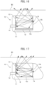
- FIG. 7 is a diagram schematically showing a side cross-section of the medical instrument according to the second arrangement example.
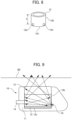
- FIG. 8 is a diagram schematically showing an external configuration of the container 12.
- the container 12 is made entirely of metal.
- three holes 12d are provided at intervals of about 120 degrees around the bottom portion 12c. It should be noted that the number of the holes 12d is not limited to three. Furthermore, the hole 12d may be provided around the middle portion 12b.
- the light emitter 16 is disposed for each hole 12d. In the example shown in FIG.
- the height from the hole 12d to the bottom portion 12c is smaller than h/3.
- the light emitted from the light emitter 16 is reflected inside the metal container 12, and reaches all layers of the soft portion 13 and all layers of the skin from the lower surface of the soft portion 13.
- the medical instrument 10 can irradiate all layers of the soft portion 13, all layers of the container 12, all layers of the skin, and the like with the light emitted from the light emitter 16, such that it is possible to reduce or prevent infection in all layers of the soft portion 13, all layers of the container 12, all layers of the skin, and other sites. Furthermore, according to the second arrangement example, with the medical instrument 10, since the light emitted from the light emitter 16 passes through the skin B2, it is possible to grasp the position of the soft portion 13 from the outside, and assist the puncture operation of the injection needle 31 when the medicinal solution is injected into the container 12.
- the container 12 since the container 12 is made entirely of metal, light does not leak from the side surface of the container 12, and the reflection toward the soft portion 13 increases. Thus, since the intensity of the light released from the soft portion 13 becomes strong, it is possible to further improve the anti-inflammatory effect at the puncture position, and it is possible to more accurately grasp the position of the soft portion 13 from the outside on the top surface side of the soft portion 13.
- the hole 12d may be provided on the bottom surface of the container 12. In this configuration, the light emitter 16 emits light upward from the position (bottom surface) of the hole 12d of the container 12.
- the container 12 may be made of metal only on its side surface, and may be made of resin on its bottom surface.
- FIG. 9 is a diagram schematically showing a side cross-section of the medical instrument 10 according to the third arrangement example.
- the bottom portion 12c is made of metal
- the middle portion 12b other than the bottom portion 12c is made of resin.
- the light emitter 16 is disposed around the bottom portion 12c of the container 12. More specifically, three light emitters 16 are disposed at intervals of about 120 degrees around the bottom portion 12c of the container 12.
- the mounting position and angle of the light emitter 16 is determined so that the light emitted from the light emitter 16 is scattered in the entire container 12, and incident from the lower surface of the soft portion 13 so as to reach all layers of the soft portion 13, all layers of the skin, and other sites.
- the light emitted from the light emitter 16 is scattered to the entire container 12 by providing the inner wall of the container 12 having an appropriate roughness.
- the number of the light emitters 16 is not limited to three.
- the medical instrument 10 can irradiate all layers of the soft portion 13, all layers of the container 12, all layers of the skin, and the like with the light emitted from the light emitter 16, such that it is possible to reduce or prevent infection in all layers of the soft portion 13, all layers of the container 12, all layers of the skin, and other sites. Furthermore, according to the third arrangement example, with the medical instrument 10, since the light emitted from the light emitter 16 passes through the skin B2, it is possible to grasp the position of the soft portion 13 from the outside, and assist the puncture operation of the injection needle 31 when the medicinal solution is injected into the container 12.
- FIG. 10 is a diagram schematically showing a side cross-section of the medical instrument 10 according to the fourth arrangement example.
- FIG. 11 is a diagram schematically showing the external configuration of the container 12 according to the fourth arrangement.
- the container 12 is made entirely of metal. Furthermore, in the fourth arrangement example, the position where the holes 12d are provided is different from that in the second arrangement example. More specifically, as shown in FIG. 11 , the container 12 has three holes 12d provided at intervals of about 120 degrees around the center of the middle portion 12b. It should be noted that the number of the holes 12d is not limited to three.
- the light emitter 16 is disposed for each hole 12d. In the example of FIG. 11 , when the dimension in the height direction of the container 12 is defined as h, the height from the hole 12d to the bottom portion 12c is h/3 or more, and is smaller than 2h/3.
- the light emitted from the light emitter 16 is reflected inside the metal container 12, and reaches all layers of the soft portion 13 and all layers of the skin from the lower surface of the soft portion 13.
- the medical instrument 10 can irradiate all layers of the soft portion 13, all layers of the container 12, all layers of the skin, and the like with the light emitted from the light emitter 16, such that it is possible to reduce or prevent infection in all layers of the soft portion 13, all layers of the container 12, all layers of the skin, and other sites. Furthermore, according to the fourth arrangement example, with the medical instrument 10, since the light emitted from the light emitter 16 passes through the skin B2, it is possible to grasp the position of the soft portion 13 from the outside, and assist the puncture operation of the injection needle 31 when the medicinal solution is injected into the container 12.
- the container 12 since the container 12 is made entirely of metal, light does not leak from the side surface of the container 12, and the reflection toward the soft portion 13 increases. Thus, since the intensity of the light released from the soft portion 13 becomes strong, it is possible to further improve the anti-inflammatory effect at the puncture position, and it is possible to more accurately grasp the position of the soft portion 13 from the outside on the top surface side of the soft portion 13.
- the container 12 may be made of metal only on its side surface, and may be made of resin on its bottom surface.
- FIG. 12 is a diagram schematically showing a side cross-section of the medical instrument 10 according to the fifth arrangement example.
- FIG. 13 is a diagram schematically showing an external configuration of the container 12 according to the fifth arrangement example.
- the container 12 is made entirely of metal.
- the position where the holes 12d are provided is different from that of the second arrangement example and the fourth arrangement example. More specifically, as shown in FIG. 13 , the container 12 has three holes 12d provided at intervals of about 120 degrees around the vicinity of the upper portion of the middle portion 12b. The number of the holes 12d is not limited to three.
- the light emitter 16 is disposed at each hole 12d.
- the direction (slope) of the light-emitting surface of the light emitter 16 when placing the light emitter 16 in each hole 12d is set as, for example, the downward direction (the direction of the bottom portion 12c of the container 12) and the horizontal direction.
- the direction of the light-emitting surface of the light emitter 16 is placed in the horizontal direction, there is an advantage in that the degree of irradiation of light to the soft portion 13 is improved.
- the dimension in the vertical direction of the container 12 is defined as h
- the height from the hole 12d to the bottom portion 12c is 2h/3 or more and is smaller than h.
- the light emitted from the light emitter 16 is reflected inside the metal container 12, and reaches all layers of the soft portion 13 and all layers of the skin from the lower surface of the soft portion 13.
- the medical instrument 10 can irradiate all layers of the soft portion 13, all layers of the container 12, all layers of the skin, and the like with the light emitted from the light emitter 16, such that it is possible to reduce or prevent infection in all layers of the soft portion 13, all layers of the container 12, all layers of the skin, and other sites. Furthermore, according to the fifth arrangement example, with the medical instrument 10, since the light emitted from the light emitter 16 passes through the skin B2, it is possible to grasp the position of the soft portion 13 from the outside, and assist the puncture operation of the injection needle 31 when the medicinal solution is injected into the container 12.
- the container 12 since the container 12 is made entirely of metal, light does not leak from the side surface of the container 12, and the reflection toward the soft portion 13 increases. Thus, since the intensity of the light released from the soft portion 13 becomes strong, it is possible to further improve the anti-inflammatory effect at the puncture position, and it is possible to more accurately grasp the position of the soft portion 13 from the outside on the top surface side of the soft portion 13.
- the container 12 may be made of metal only on its side surface, and may be made of resin on its bottom surface.
- FIG. 14 is a diagram schematically showing a side cross-section of the medical instrument 10 according to the sixth arrangement example.
- the container 12 is made entirely of metal.
- the hole 12d is not provided in the container 12.
- Three light emitters 16 are arranged at intervals of about 120 degrees around the soft portion 13. The number of the light emitters 16 is not limited to three.
- the light emitted from the light emitter 16 is reflected inside the metal container 12, and reaches all layers of the soft portion 13 and all layers of the skin from the lower surface of the soft portion 13.
- the medical instrument 10 can irradiate all layers of the soft portion 13, all layers of the container 12, all layers of the skin, and the like with the light emitted from the light emitter 16, such that it is possible to reduce or prevent infection in all layers of the soft portion 13, all layers of the container 12, all layers of the skin, and other sites.
- the medical instrument 10 since it is possible to improve the degree of irradiation of light to the soft portion 13, it is possible to improve the reduction of or prevent infection in all layers of the soft portion 13.
- the medical instrument 10 since the light emitted from the light emitter 16 passes through the skin B2, it is possible to grasp the position of the soft portion 13 from the outside, and assist the puncture operation of the injection needle 31 when the medicinal solution is injected into the container 12. Further, in the sixth arrangement example, since the light emitter 16 is arranged to irradiate the soft portion 13 around the soft portion 13, the light is efficiently diffused by the soft portion 13, so that the anti-inflammatory effect can be further improved and the position of the soft portion 13 can be grasped more accurately from the outside on the top surface side of the soft portion 13.
- FIG. 15 is a diagram schematically showing a side cross-section of the medical instrument 10 according to the seventh arrangement example.
- the bottom portion 12c is made of metal
- the middle portion 12b other than the bottom portion 12c is made of resin.
- the position where the light emitters 16 are arranged is different from that in the third arrangement example.
- the light emitters 16 are disposed around the vicinity of the middle of the middle portion 12b of the container 12. More specifically, three light emitters 16 are arranged at intervals of 120 degrees around the vicinity of the middle of the middle portion 12b of the container 12.
- the mounting position and angle of the light emitter 16 is determined so that the light emitted from the light emitter 16 is scattered in the entire container 12, and incident from the lower surface of the soft portion 13 so as to reach all layers of the soft portion 13, all layers of the skin, and other sites.
- the light emitted from the light emitter 16 is scattered to the entire container 12 by providing the inner wall of the container 12 having an appropriate roughness.
- the number of the light emitters 16 is not limited to three.
- the medical instrument 10 can irradiate all layers of the soft portion 13, all layers of the container 12, all layers of the skin, and the like with the light emitted from the light emitter 16, such that it is possible to reduce or prevent infection in all layers of the soft portion 13, all layers of the container 12, all layers of the skin, and other sites. Furthermore, according to the seventh arrangement example, with the medical instrument 10, since the light emitted from the light emitter 16 passes through the skin B2, it is possible to grasp the position of the soft portion 13 from the outside, and assist the puncture operation of the injection needle 31 when the medicinal solution is injected into the container 12.
- FIG. 16 is a diagram schematically showing a side cross-section of the medical instrument 10 according to the eighth arrangement example.
- the bottom portion 12c is made of metal
- the middle portion 12b other than the bottom portion 12c is made of resin.
- the position where the light emitters 16 are arranged is different from that of the third arrangement example and the seventh embodiment.
- the light emitters 16 are disposed around the vicinity of the upper portion of the middle portion 12b of the container 12. More specifically, three light emitters 16 are arranged at intervals of 120 degrees around the vicinity of the upper portion of the middle portion 12b of the container 12.
- the mounting position and angle of the light emitter 16 are determined so that the light emitted from the light emitter 16 is scattered in the entire container 12, and incident from the lower surface of the soft portion 13 so as to reach all layers of the soft portion 13, all layers of the skin, and other sites.
- the light emitted from the light emitter 16 is scattered to the entire container 12 by providing the inner wall of the container 12 having an appropriate roughness.
- the number of the light emitters 16 is not limited to three.
- the medical instrument 10 can irradiate all layers of the soft portion 13, all layers of the container 12, all layers of the skin, and the like with the light emitted from the light emitter 16, such that it is possible to reduce or prevent infection in all layers of the soft portion 13, all layers of the container 12, all layers of the skin, and other sites. Furthermore, according to the eighth arrangement example, with the medical instrument 10, since the light emitted from the light emitter 16 passes through the skin B2, it is possible to grasp the position of the soft portion 13 from the outside, and assist the puncture operation of the injection needle 31 when the medicinal solution is injected into the container 12.
- FIG. 17 is a diagram schematically showing a side cross-section of the medical instrument 10 according to the ninth arrangement example.
- the container 12 is made entirely of resin.
- the position where the light emitters 16 are arranged and the number of the light emitters 16 are different from those in the first arrangement example.
- the light emitters 16 are disposed around the edge of the bottom portion 12c of the container 12 and around the middle portion 12b. More specifically, three light emitters 16 are arranged at intervals of 120 degrees around the edge of the middle portion 12b of the container 12. In addition, three light emitters 16 are arranged at intervals of 120 degrees around the middle portion 12b of the container 12.
- the mounting position and angle of the light emitter 16 is determined so that the light emitted from the light emitter 16 is scattered in the entire container 12, and incident from the lower surface of the soft portion 13 so as to reach all layers of the soft portion 13, all layers of the skin, and other sites.
- the light emitted from the light emitter 16 is scattered to the entire container 12 by providing the inner wall of the container 12 having an appropriate roughness.
- the number of the light emitters 16 is not limited to six.
- the medical instrument 10 can irradiate all layers of the soft portion 13, all layers of the container 12, all layers of the skin, and the like with the light emitted from the light emitter 16, such that it is possible to reduce or prevent infection in all layers of the soft portion 13, all layers of the container 12, and all layers of the skin.
- the entire container 12 is made of resin, but the present invention is not limited to this configuration, and the container 12 may be made entirely of metal, or the bottom portion may be made of metal (portions other than the bottom portion may be made of resin).
- the medical instrument 10 since the light emitted from the light emitter 16 passes through the skin B2, it is possible to grasp the position of the soft portion 13 from the outside, and assist the puncture operation of the injection needle 31 when the medicinal solution is injected into the container 12.
- FIG. 18 is a diagram schematically showing a side cross-section of the medical instrument 10 according to the tenth arrangement example.
- the container 12 is made entirely of resin.
- the position where the light emitters 16 are arranged and the number of the light emitters 16 are different from those of the first arrangement example and the ninth arrangement example.
- the light emitters 16 are disposed around the edge of the bottom portion 12c of the container 12, around the vicinity of the middle portion of the middle portion 12b, and around the vicinity of the upper portion of the middle portion 12b. More specifically, three light emitters 16 are arranged at intervals of 120 degrees around the edge of the middle portion 12b of the container 12.
- three light emitters 16 are arranged at intervals of 120 degrees around the vicinity of the center of the middle portion 12b of the container 12. In addition, three light emitters 16 are arranged at intervals of 120 degrees around the vicinity of the upper portion of the middle portion 12b of the container 12.
- the mounting positions and angles of the respective light emitters 16 are determined so that the light emitted from the light emitter 16 is scattered in the entire container 12, and incident from the lower surface of the soft portion 13 so as to reach all layers of the soft portion 13. For example, it is considered that the light emitted from the respective light emitters 16 is scattered to the entire container 12 by providing the inner wall of the container 12 having an appropriate roughness.
- the number of the light emitters 16 is not limited to nine.
- the medical instrument 10 can irradiate all layers of the soft portion 13, all layers of the container 12, all layers of the skin, and the like with the light emitted from the light emitter 16, such that it is possible to reduce or prevent infection in all layers of the soft portion 13, all layers of the container 12, and all layers of the skin.
- the entire container 12 is made of resin, but the present invention is not limited to this configuration, and the container 12 may be made entirely of metal, or the bottom portion may be made of metal (portions other than the bottom portion may be made of resin).
- the medical instrument 10 since the light emitted from the light emitter 16 passes through the skin B2, it is possible to grasp the position of the soft portion 13 from the outside, and assist the puncture operation of the injection needle 31 when the medicinal solution is injected into the container 12.
- FIG. 19 is a diagram schematically showing a side cross-section of the medical instrument 10 according to the eleventh arrangement example.
- FIG. 20 is a diagram schematically showing a top surface of the medical instrument 10 according to the eleventh arrangement example.
- the container 12 is made entirely of resin.
- the position where the light emitters 16 are arranged is different from that in the first arrangement example.
- the light emitters 16 are disposed at any position within the main body 11 that does not contact the living body from the middle portion 12b toward a tip side 11a of the main body 11.
- the tip side 11a of the main body 11 refers to a side on which the injector 14 is not provided. Unlike the other locations, the tip side 11a has room to arrange the light emitter 16 at any position.
- the respective light emitters 16 are arranged so that the center portions, i.e., the center axes, are oriented in a predetermined direction.
- the center portion refers to a portion where the light emitter 16 is most intensely illuminated.
- the predetermined direction refers to a direction passing through a predetermined location (e.g., the center) of the container 12 or a direction passing through a predetermined location (e.g., the center) of the soft portion 13.
- the number of the light emitters 16 is not limited to three.
- the light emitted from the respective light emitters 16 is scattered to the entire container 12 by providing the inner wall of the container 12 having an appropriate roughness.
- the medical instrument 10 can irradiate all layers of the soft portion 13, all layers of the container 12, all layers of the skin, and the like with the light emitted from the light emitter 16, such that it is possible to reduce or prevent infection in all layers of the soft portion 13, all layers of the container 12, and all layers of the skin. Furthermore, according to the eleventh arrangement example, with the medical instrument 10, since the light emitted from the light emitter 16 passes through the skin B2, it is possible to grasp the position of the soft portion 13 from the outside, and assist the puncture operation of the injection needle 31 when the medicinal solution is injected into the container 12.
- FIG. 21 is a diagram schematically showing a side cross-section of the medical instrument 10 according to the twelfth arrangement example.
- FIG. 22 is a diagram schematically showing a top surface of the medical instrument 10 according to the twelfth arrangement example.
- the container 12 is made entirely of resin.
- the medical instrument 10 includes an optical fiber 17.
- the optical fiber 17 is free to bend into a variety of shapes, and is wound around the soft portion 13 and the container 12, as shown in FIG. 21 . Furthermore, the optical fiber 17 has one end coupled to the light emitting surface of the light emitter 16.
- the coupling method between the light emitter 16 and the optical fiber 17 is not particularly limited as long as it is a low loss coupling, and includes butt coupling, lens coupling, and other couplings.
- the optical fiber 17 is a material or structure that conveys light in the lateral direction and, for example, is a diffuse optical fiber.
- the medical instrument 10 causes the entire optical fiber 17 to emit light by using the light emitted from the light emitting section 16, all layers of the soft portion 13 and all layers of the container 12 can be irradiated by the light emitted from the optical fiber 17, thereby reducing or preventing infection in all layers of the soft portion 13 and all layers of the container 12. Furthermore, according to the twelfth arrangement example, with the medical instrument 10, since the light emitted from the side surface of the optical fiber 17 wound around the soft portion 13 passes through the skin B2, it is possible to grasp the position of the soft portion 13 from the outside, and assist the puncture operation of the injection needle 31 when the medicinal solution is injected into the container 12.
- the medical instrument 10 may include a light emitter 16c that contributes to a marker function and a light emitter 16d that contributes to the reduction or prevention of an infection.
- a light emitter 16c that contributes to a marker function
- a light emitter 16d that contributes to the reduction or prevention of an infection.
- FIG. 23 is a diagram schematically showing a side cross-section of the medical instrument 10 according to the thirteenth arrangement example.
- FIG. 24 is a diagram schematically showing a top surface of the medical instrument 10 according to the thirteenth arrangement example.
- the container 12 is made entirely of resin.
- the light emitters 16c are disposed around the soft portion 13. More specifically, the light emitters 16c include three light emitters, and are arranged at intervals of about 120 degrees around the soft portion 13. The number of the light emitters 16c is not limited to three.
- the light emitter 16c emits light in accordance with the proximity of the power transmitter 20 (the second coil 21).
- the light emitted from the light emitter 16c can be visually recognized from outside the body through the skin B2.
- the top surface of the soft portion 13 is located in the vicinity of the center of the locations where light is emitted at three locations. Furthermore, according to the thirteenth arrangement example, with the medical instrument 10, since the light emitted from the light emitter 16c passes through the skin B2, it is possible to grasp the position of the soft portion 13 from the outside, and assist the puncture operation of the injection needle 31 when the medicinal solution is injected into the container 12.
- the light emitter 16d is disposed around the bottom portion 12c of the container 12. More specifically, the light emitter 16d includes three light emitters, which are arranged at intervals of about 120 degrees around the bottom portion 12c of the container 12. The number of the light emitters 16d is not limited to three. Since the light emitted from the light emitter 16d irradiates all layers of the soft portion 13, all layers of the container 12, all layers of the skin, and the like, it is possible to reduce or prevent infection in all layers of the soft portion 13, all layers of the container 12, and all layers of the skin.
- the medical instrument 10 since the medical instrument 10 includes the light emitter 16c and the light emitter 16d, it is possible to exhibit a marker function when puncturing with the injection needle 31 to inject the medicinal solution into the container 12, and it is also possible to achieve the reduction or prevention of infection, in addition to hygiene when puncturing with the injection needle 31.
- the treatment of injecting the medicinal solution into the container 12 is completed within about several minutes, but the irradiation of the light for reducing or preventing infection requires 5 minutes to 1 hour, depending on the center wavelength of the light emitted from the light emitter 16d and the magnitude of the irradiance.
- the medical instrument 10 may receive power transmitted from the power transmitter 20, start light emission by the light emitter 16d to reduce or prevent infection, emit light by the light emitter 16c after a predetermined time has elapsed, specify the position of the soft portion 13, and inject a medicinal solution into the container 12.
- the medical instrument 10 may include a secondary battery therein. The medical instrument 10 charges the internal secondary battery with the power received from the power transmitter 20.
- the medical instrument 10 receives the power transmitted from the power transmitter 20, and emits light from the light emitters 16c and 16d, and specifies the position of the soft portion 13 by the light emitter 16c and punctures with the injection needle 31 while reducing or preventing infection by the light emitter 16d.
- the medical instrument 10 stops the power transmitted from the power transmitter 20 after the end of the puncture of the injection needle 31, and continues the light emission of the light emitter 16d by the power of the secondary battery to reduce or prevent infection. Furthermore, it may be configured to stop the power transmitted from the power transmitter 20 after charging the secondary battery.
- the medical instrument 10 emits light from the light emitters 16c and 16d by the power of the secondary battery, specifies the position of the soft portion 13 by the light emitter 16c, and punctures with the injection needle 31 while reducing or preventing infection by the light emitter 16d. Therefore, since the medical instrument 10 can puncture with the injection needle 31 while causing the light emitter 16c to emit light by the power of the secondary battery, it is possible to puncture with the injection needle 31 without being limited to the location where the power transmitter 20 is disposed.
- FIG. 24 it is preferable to provide one of the light emitters 16d at a position facing the injector 14 so as to irradiate the injector 14 with light.
- A2 in FIG. 24 indicates an irradiation site (range) A2 of the light (blue light) emitted from the light emitter 16d.
- the medical instrument 10 irradiates the entire injector 14 with light (blue light) emitted from the light emitter 16d, such that it is possible to reduce or prevent infection in the injector 14 which is an inlet of the catheter C.
- red light light having a center wavelength of 600 nm to 1100 nm
- blue light light having a center wavelength of 400 nm to 480 nm.
- the effect of the anti-inflammatory effect on these can be expected. This is because it is considered that irradiation with red light may have a direct effect on Staphylococcus aureus or may enhance the action of neutrophils.
- the present invention is not limited to this configuration (a configuration in which light is irradiated from the interior of the living body B1), and irradiation of light may be performed from outside the living body B1.
- the radiant exposure of red light for each sample was set as 10 [J/cm 2 ], 30 [J/cm 2 ], and 60 [J/cm 2 ].
- the illumination intensity of red light was set as 12 [mW/cm 2 ] for all the samples.
- a sample not irradiated with red light was used as a control.
- FIG. 25A is an image showing a status of methicillin-resistant Staphylococcus aureus (MRSA) colonies formed on a control agar-culture medium after 48 hours of incubation.
- FIG. 25B is an image showing the status of the colonies formed on an agar-culture medium after red-light irradiation at a radiant exposure of 60 [J/cm 2 ] and after 48 hours of incubation.
- colonies were formed on both the control and the sample irradiated with red light of 60 [J/cm 2 ], and it was confirmed that the number of colonies in the sample irradiated with red light of 60 [J/ cm 2 ] was smaller than the number of colonies in the control.
- [Table 1] RADIANT EXPOSURE (J/cm 2 ) CONTROL 10 30 60 NUMBER OF COLONIES (WHEN NORMALIZED BY NUMBER OF COLONIES OF CONTROL) 1 0.97 0.82 0.5
- neutrophils which are blood components
- this test result strongly suggests that the antibacterial effect can be obtained even in the living tissue in which the blood components exist in the surrounding tissue, and that the infection related to the medical instrument implanted in a body can be reduced or prevented by the weak light.
- an antimicrobial effect can be expected with a smaller radiant exposure.
Landscapes
- Health & Medical Sciences (AREA)
- Life Sciences & Earth Sciences (AREA)
- Animal Behavior & Ethology (AREA)
- General Health & Medical Sciences (AREA)
- Public Health (AREA)
- Veterinary Medicine (AREA)
- Heart & Thoracic Surgery (AREA)
- Biomedical Technology (AREA)
- Engineering & Computer Science (AREA)
- Anesthesiology (AREA)
- Pulmonology (AREA)
- Epidemiology (AREA)
- Hematology (AREA)
- Gastroenterology & Hepatology (AREA)
- Biophysics (AREA)
- Pathology (AREA)
- Nuclear Medicine, Radiotherapy & Molecular Imaging (AREA)
- Radiology & Medical Imaging (AREA)
- Infusion, Injection, And Reservoir Apparatuses (AREA)
Abstract
Description
- The present disclosure relates to an implantable medical instrument for use within the body of a subject, and a medical device including the medical instrument.
- A body-implantable medical device in which a body portion of a medical instrument is implanted into a body is used for charging a medicinal solution into the body (for example, refer to
Japanese Unexamined Patent Application, Publication No. 2007-203070
This medical instrument reduces the burden on patients who need frequent injections for charging a medicinal solution. Such a medical instrument has a soft portion through which an injection needle is inserted into the body portion. This soft portion is made of, for example, silicone rubber or other materials. With the medical instrument, a medicinal solution is injected into a medicinal solution container through the soft portion. The medicinal solution is transported through a catheter to blood vessels. - Patent Document 1:
Japanese Unexamined Patent Application, Publication No. 2007-203070 - As described above, after this medical instrument is implanted within the patient's body, it is necessary to puncture periodically with an injection needle for charging a medicinal solution. However, puncturing with an injection needle may cause bacteria to grow in the skin covering the medical instrument and in the interior of the medical instrument including the soft portion, thereby causing an infection. Therefore, it is desired to reduce or prevent infection.
- An exemplary embodiment of the present disclosure provides a medical instrument that makes it possible to reduce or prevent an infection, and a medical device including the medical instrument.
- An exemplary embodiment of the present invention provides an implantable medical instrument for use within a body, the medical instrument including a container that has an opening and holds a medicinal solution, and a soft portion that closes the opening, the medical instrument including: a power receiver that receives power transmitted externally; and a light emitter that emits light by way of the power received by the power receiver, in which the light emitter includes at least one of a first light emitter that emits light having a center wavelength of 600 nm or more and 1100 nm or less, and a second light emitter that emits light having a center wavelength of 400 nm or more and 480 nm or less.
- Furthermore, in the above medical instrument, the light emitter is provided around the soft portion, and irradiates at least a top surface of the soft portion.
- Furthermore, in the above medical instrument, the light emitter is disposed around a middle portion or a bottom portion of the container, and irradiates at least an interior of the container and the soft portion.
- Furthermore, in the above medical instrument, the light emitter includes at least the first light emitter, and a radiant exposure of the light emitted from the first light emitter is in a range from 1.0 to 100.0 J/cm2 at an irradiation target site.
- Furthermore, in the above medical instrument, the light emitter includes at least the first light emitter, and the first light emitter emits light having a center wavelength of 620 nm, 660 nm, 680 nm, 760 nm, or 820 nm.
- Furthermore, in the above medical instrument, the light emitter includes at least the second light emitter, and a radiant exposure of the light emitted from the second light emitter is in a range from 32 to 125 J/cm2 at an irradiation target site.
- An exemplary embodiment of the present invention provides a medical device including a medical instrument according to any one of the above medical instruments; and a power transmitter that transmits predetermined power, in which the medical instrument further includes a power receiver that receives power transmitted from the power transmitter.
- According to an exemplary embodiment of the present disclosure, it is possible to reduce or prevent an infection.
-
-
FIG. 1 is a diagram schematically showing a schematic configuration of a medical device according to an exemplary embodiment of the present disclosure. -
FIG. 2 is a diagram schematically showing a side cross-section of a medical instrument. -
FIG. 3 is a diagram schematically showing a top surface of a medical instrument. -
FIG. 4 is a diagram schematically showing a side cross-section of a medical instrument. -
FIG. 5 is a diagram showing a configuration example of a power receiver and a light emitter. -
FIG. 6 is a diagram schematically showing a side cross-section of a medical instrument according to a first arrangement example. -
FIG. 7 is a diagram schematically showing a side cross-section of a medical instrument according to a second arrangement example. -
FIG. 8 is a diagram schematically showing an external configuration of a container according to the second arrangement example. -
FIG. 9 is a diagram schematically showing a side cross-section of a medical instrument according to a third arrangement example. -
FIG. 10 is a diagram schematically showing a side cross-section of a medical instrument according to a fourth arrangement example. -
FIG. 11 is a diagram schematically showing an external configuration of a container according to the fourth arrangement. -
FIG. 12 is a diagram schematically showing a side cross-section of a medical instrument according to a fifth arrangement example. -
FIG. 13 is a diagram schematically showing an external configuration of a container according to the fifth arrangement example. -
FIG. 14 is a diagram schematically showing a side cross-section of a medical instrument according to a sixth arrangement example. -
FIG. 15 is a diagram schematically showing a side cross-section of a medical instrument according to a seventh arrangement example. -
FIG. 16 is a diagram schematically showing a side cross-section of a medical instrument according to an eighth arrangement example. -
FIG. 17 is a diagram schematically showing a side cross-section of a medical instrument according to a ninth arrangement example. -
FIG. 18 is a diagram schematically showing a side cross-section of the medical instrument according to the tenth arrangement example. -
FIG. 19 is a diagram schematically showing a side cross-section of a medical instrument according to an eleventh arrangement example. -
FIG. 20 is a diagram schematically showing a top surface of the medical instrument according to the eleventh arrangement example. -
FIG. 21 is a diagram schematically showing a side cross-section of a medical instrument according to a twelfth arrangement example. -
FIG. 22 is a diagram schematically showing a top surface of the medical instrument according to the twelfth arrangement example. -
FIG. 23 is a diagram schematically showing a side cross-section of a medical instrument according to a thirteenth arrangement example. -
FIG. 24 is a diagram schematically showing a top surface of the medical instrument according to the thirteenth arrangement example. -
FIG. 25A is an image showing a status of methicillin-resistant Staphylococcus aureus (MRSA) colonies formed on a control agar-culture medium after 48 hours of incubation. -
FIG. 25B is an image showing the status of methicillin-resistant Staphylococcus aureus (MRSA) colonies formed on an agar-culture medium after red-light irradiation at a radiant exposure of 60 [J/cm2] and after 48 hours of incubation. - Hereinafter, exemplary embodiments for carrying out the present disclosure will be described in detail with reference to the accompanying drawings. It should be noted that the present disclosure is not limited to the following exemplary embodiments. In addition, the drawings referred to in the following description are merely schematic representations of the shape, size, and positional relationship to the extent that the content of the present disclosure can be understood. That is, the present disclosure is not limited to the shapes, sizes, and positional relationships illustrated in the drawings. Furthermore, in the following description, configurations and operations of an implantable medical instrument for use within a living body of a subject including a human and an animal, and a medical device including the medical instrument will be described in detail.
-
FIG. 1 schematically shows a state when amedical instrument 10 is implanted into the body of a patient, andFIG. 1 is a diagram schematically showing a configuration of a medical device 1. The medical device 1 includes themedical instrument 10 and apower transmitter 20. Themedical instrument 10 is, for example, referred to as a subcutaneous implantable port (CV port), and is an implantable instrument for use which includes a container having an opening closed by a soft portion and holding a medicinal solution therein.FIG. 1 schematically shows a state in which themedical instrument 10 is implanted in a patient's body B1. - The configuration and operation of the
medical instrument 10 will be described below. Themedical instrument 10 includes asoft portion 13 through which aninjection needle 31 is inserted, and acontainer 12 that holds a medicinal solution injected by theinjection needle 31. In this exemplary embodiment, a surface of thesoft portion 13 through which theinjection needle 31 is inserted is referred to as a top surface of themedical instrument 10, a surface opposing the top surface is referred to as a bottom surface of themedical instrument 10, and a surface connecting the top surface and the bottom surface is referred to as a side surface of themedical instrument 10. -
FIG. 2 is a diagram schematically showing a side cross-section of themedical instrument 10.FIG. 3 is a diagram schematically showing a top surface of themedical instrument 10. As shown inFIG. 2 , themedical instrument 10 mainly includes amain body 11, thecontainer 12 having anopening 12a and holding a medicinal solution, and thesoft portion 13 that closes theopening 12a of thecontainer 12. Furthermore, themedical instrument 10 includes an injector (catheter port) 14 to which a catheter C is connected and which injects a solution contained in thecontainer 12 into a blood vessel (vein) B through the catheter C. - The
main body 11 is, for example, a housing made of epoxy resin or other materials. Thecontainer 12 is a tank that temporarily stores a medicinal solution. Thecontainer 12 includes theopening 12a in the vicinity of the outside of the living body. Theopening 12a has a circular or substantially circular shape.FIG. 2 shows that theopening 12a is closed by thesoft portion 13. Thecontainer 12 may be made entirely of metal, may be made entirely of resin, or may be made of metal only at the bottom portion and may be made of resin at the other portions than the bottom portion. - The
soft portion 13 is referred to as a septum. Thesoft portion 13 closes theopening 12a of thecontainer 12. Thesoft portion 13 is, for example, a soft lid body (silicone diaphragm) made of silicone rubber, and is exposed from themain body 11 as well. Furthermore, thesoft portion 13 has a columnar or substantially columnar shape. However, it may have a shape other than a columnar shape. Thesoft portion 13 is a portion through which theinjection needle 31 for the injection (infusion) of a medicinal solution can be inserted from a body surface of a subject after themain body 11 is implanted within the living body B1. It should be noted thatFIG. 1 schematically shows the external shape of themedical instrument 10. Therefore, various shapes may be available to themain body 11, thecontainer 12, and other components. Theinjection needle 31 is, for example, a Huber needle. After being inserted into thesoft portion 13, a medicinal solution or other liquid is injected into thecontainer 12 from the tip of theinjection needle 31. - Furthermore, the
medical instrument 10 includes apower receiver 15 andlight emitters 16. Thepower receiver 15 receives power transmitted from the outside (a power transmitter 20). Thelight emitters 16 are for example, LEDs (light emitting diode), and each emits light by the power received by thepower receiver 15. Furthermore, thelight emitters 16 each include at least one of afirst light emitter 16a that emits light having a center wavelength of 600 nm or more and 1100 nm or less, and asecond light emitter 16b that emits light having a center wavelength of 400 nm or more and 480 nm or less. That is, thelight emitter 16 may include only thefirst light emitter 16a, thelight emitter 16 may include only thesecond light emitter 16b, or thelight emitter 16 may include both thefirst light emitter 16a and thesecond light emitter 16b. In the present exemplary embodiment, when expressed as "light emitter 16", the "light emitter 16" indicates thefirst light emitter 16a or thesecond light emitter 16b. The range on the long wavelength side (600 nm or more and 1100 nm or less) and the range on the short wavelength side (400 nm or more and 480 nm or less) described above were each specified by the inventors and other by undertaking extensive effort. - The
light emitters 16 are disposed around thesoft portion 13, and irradiate at least the top surface of thesoft portion 13. For example, thelight emitters 16 are disposed in an annular or substantially annular manner at predetermined intervals around thesoft portion 13. More specifically, when threelight emitters 16 are used, each of thelight emitters 16 is disposed in an annular or substantially annular manner around thesoft portion 13 at intervals of about 120 degrees, as shown inFIG. 3 . Thelight emitter 16 may be sloped by a predetermined angle toward the center of thesoft portion 13 so as to irradiate the top surface of thesoft portion 13. It should be noted that the number oflight emitters 16 and the position and angle to be arranged can be appropriately changed. - With such a configuration, the
medical instrument 10 can irradiate at least the top surface of thesoft portion 13 by arranging thelight emitters 16 around thesoft portion 13, such that infection caused on the top surface of thesoft portion 13 can be reduced or prevented, as described below. - Furthermore, the
light emitter 16 may be disposed around amiddle portion 12b or abottom portion 12c of thecontainer 12 to irradiate at least the interior of thecontainer 12 and thesoft portion 13.FIG. 4 is a diagram schematically showing a side cross-section of themedical instrument 10. More specifically,FIG. 4 schematically shows an example in which thelight emitter 16 is disposed around thebottom portion 12c of thecontainer 12. - With such a configuration, the
medical instrument 10 can irradiate at least the interior of thecontainer 12 and thesoft portion 13 by disposing thelight emitter 16 around themiddle portion 12b or around thebottom portion 12c of thecontainer 12, such that infection caused in the interior of thecontainer 12 and thesoft portion 13 can be reduced or prevented. - In
FIG. 2 , although an irradiation site (range) A1 by thelight emitter 16 is shown schematically so that it may target only a portion beneath the skin (the surface of the soft portion 13), the irradiation site (range) by thelight emitter 16 is not limited to this region. Although a detailed configuration will be described later, it is possible to irradiate various sites by changing the position and angle where thelight emitter 16 is disposed, and the number of thelight emitters 16. The various sites may include not only the portion beneath the skin (the surface of the soft portion 13), but also the following sites, for example. - 1. All layers of the skin (including epidermis and dermis) only
- 2. All layers of the skin and portions beneath the skin (the surface of the soft portion 13)
- 3. All layers of the skin and all layers of the
soft portion 13 - 4. All layers of the skin, all layers of the
soft portion 13, and all layers of the container 12 (the entire container 12) - 5. All layers of the skin, all layers of the
soft portion 13, all layers of thecontainer 12, andentire injector 14 - In addition, the range of radiant exposure (radiation dose) E1 of the light emitted from the
first light emitter 16a can be set as, for example, 1.0 to 100.0 [J/cm2] at the irradiation target site from the viewpoint of influences on the human body and working efficiencies. Here, the radiant exposure will be described. The radiant exposure E is calculated by an irradiance I of the illumination (irradiation) and the irradiation time t as shown in expression (1). The irradiance refers to the radiant flux incident per unit area. E[J/cm2] = I[W/cm2] × t[s] ...(1) - For example, when the irradiance I is "4.5 × 10⁻³[W/cm2]" and the exposure time t is about "1100[s]", then the radiant exposure E1 is "4.95 [J/cm2]". In addition, when the irradiance I is "10 × 10-3[W/cm2]" and the exposure time t is about "550[s]", the radiant exposure E1 is "5.5 [J/cm2]". It should be noted that the range of the irradiance I can be set as 4 to 500 [mW per cm2]. The irradiance I can be measured, for example, by using a spectroradiometer (JIS C 1609-1: 2006 general class AA illuminometer) .
- Furthermore, the radiant exposure E1 may range from 1.0 to 100.0 [J/cm2]. In a living body environment in which neutrophils, which are blood components, are present, the radiant exposure E1 ranges preferably 1.0 to 20.0 [J/cm2], and more preferably 2.0 to 8.8 [J/cm2]. In a living body environment in which neutrophils are not present, for example in the stratum corneum of the skin, the radiant exposure E1 ranges preferably 1 to 100 [J/cm2], more preferably 1 to 60 [J/cm2], and even more preferably 10 to 60 [J/cm2].
- Furthermore, the
first light emitter 16a emits light having a center wavelength of 620 [nm], 660 [nm], 680 [nm], 760 [nm], or 820 [nm]. It should be noted that, when the center wavelength falls in the range of X±10 [nm], the center wavelength can be regarded as X [nm]. Furthermore, the center wavelengths described above are merely examples, and are not limited to these wavelengths. - Furthermore, the radiant exposure E2 of the light emitted from the
second light emitter 16b may range from 32 to 125 [J/cm2] at the irradiation target site. More specifically, for example, the radiant exposure E2 is 125 [J/cm2], preferably 62 [J/cm2], and more preferably 32 [J/cm2]. - For example, when the irradiance I is "8.74×10⁻³[W/cm2]" and the irradiation time t is about "3600 [s]", the radiant exposure E2 is "31.46 [J/cm2]". In addition, when the irradiance I is "8.6×10⁻³[W/cm2]" and the irradiation time t is about 7200 [s], the radiant exposure E2 is "61.92 [J/ cm2]". It should be noted that the range of irradiance I may be 7 to 12 [mW/cm2].
- Here, the effect of the light emitted from the
first light emitter 16a, i.e., reduction or prevention of an infection, will be described. The living body effect produced when light in the red region or the near infrared region is irradiated with the irradiance and radiant exposure to such an extent that no thermal action occurs in the living body is called Photobiomodulation (PBM). In PBM, the irradiation light is considered to be absorbed by an enzyme in the respiratory metabolism mechanism of the cell, and various effects are expressed depending on the situations of the cell and the living tissue. - In addition, various effects such as healing of infected wounds and anti-inflammatory effect have been reported by performing PBM. These are known as typical PBM effects. In this disclosure, these effects are collectively referred to as reduction or prevention of an infection, or infection control. In addition, the following paper is referred to for the PBM irradiation conditions and mechanism. T Walski et al., "The effect of red-to-near-infrared (R/NIR) irradiation on inflammatory processes", Int J Rad Biol, Vol. 95, No. 9, p.1326-1336, 2019.
- Next, the effect of the light emitted from the
second light emitter 16b, i.e., reduction or prevention of an infection, will be described. The effect of irradiation with light (blue light) on the disinfection of pathogenic microorganisms (e.g., Staphylococcus aureus) has been reported in the following paper. Yucheng Wang, Ying Wang, Yuguang Wang, Clinton K. Murray, Michael R. Hamblin, David C. Hooper, Tianhong Dai, "Antimicrobial blue light inactivation of pathogenic microbes", Drug Resistance Updates Vol. 33-35, P. 1-22 (2017) - Furthermore, the effective depth (distance) in the biological tissue is considered to be less than 1 (mm). Therefore, the
second light emitter 16b is not suitable for the sterilization of biological tissues (other than the irradiated surface), and thus, it is considered to be used for the sterilization of, for example, the surface of thecontainer 12 and the surface of theinjector 14, or the sterilization of a transparent portion. - The configuration and operation of the
power transmitter 20 will be described. Thepower transmitter 20 transmits predetermined power. Thepower transmitter 20 includes asecond coil 21 and apower supply 22. Thesecond coil 21 has an annular or substantially annular shape of a predetermined diameter (for example, approximately the outer diameter of the soft portion to be described later), and generates a magnetic flux corresponding to the power supplied from thepower supply 22. Thepower receiver 15 of themedical instrument 10 receives power transmitted from thepower transmitter 20. - As shown in
FIG. 2 , thepower receiver 15 includes afirst coil 15a and apower receiving circuit 15b. Thefirst coil 15a receives power transmitted from thepower transmitter 20. Thepower receiving circuit 15b uses the power generated in thefirst coil 15a (induced electromotive force), to cause thelight emitter 16 to emit light. - Although an example is shown in which one
light emitter 16 is provided, the number oflight emitters 16 is not limited to one, and may be two or more. - Furthermore,
FIG. 2 shows an example in which thelight emitter 16 and thepower receiver 15 are provided as a set. However, thelight emitter 16 and thepower receiver 15 may not be provided as a set.FIG. 5 is a diagram showing an example in which onepower receiver 15 and two light emitters 16_1 and 16_2 are provided. Thepower receiver 15 is disposed in the vicinity of thesoft portion 13. The vicinity of thesoft portion 13 refers to the interior or the surface of themain body 11 in the vicinity where thesoft portion 13 is located. In this manner, since thepower receiver 15 is disposed in the vicinity of thesoft portion 13, and thepower receiver 15 is located at a location in the vicinity of the skin B2 when themedical instrument 10 is implanted in the body, thepower receiver 15 can receive the power transmitted from thepower transmitter 20 with high sensitivity. - In addition, the light emitter 16_1 is disposed around the
middle portion 12b of thecontainer 12. The light emitter 16_2 is disposed around thebottom portion 12c of thecontainer 12. It should be noted that the light emitters 16_1 and 16_2 may be provided at locations other than those described above. - With such a configuration, since the
medical instrument 10 causes the light emitter 16_1 and the light emitter 16_2 to emit light by the power received by thepower receiver 15, respectively, it is possible to irradiate various regions (for example, all layers of thesoft portion 13 and all layers of thecontainer 12, etc.), such that it is possible to reduce or prevent an infection on various regions. It should be noted that thepower receiver 15 may cause the light emitter 16_1 and the light emitter 16_2 to emit light at the same time, or alternatively, may cause them to emit light with a time difference. Furthermore, the light emitter 16_1 and the light emitter 16_2 may have the same center wavelength or different center wavelengths. For example, the light emitter 16_1 may be thefirst light emitter 16a, and the light emitter 16_2 may be thesecond light emitter 16b. Furthermore, the light emitter 16_1 may be thesecond light emitter 16b, and the light emitter 16_2 may be thefirst light emitter 16a. - In addition, the
medical instrument 10 can reduce or prevent infection by the anti-inflammatory effect on the irradiated portion by causing thelight emitter 16 to emit light by the power transmitted from thepower transmitter 20 at a predetermined time period (for example, before injecting the medicinal solution into thecontainer 12 by the injection needle 31) and irradiating a predetermined location (for example, the top surface of the soft portion 13) with the light. - Here, the principle of the anti-inflammatory effect will be explained. It has been reported that PBM using light of a predetermined wavelength (for example, 660 [nm]) in a living body has an effect of reducing or preventing the growth of Staphylococcus aureus, which is the most common bacterium related to infection. It is thought to be effective in reducing or preventing the respiratory metabolism of Staphylococcus aureus and in enhancing the phagocytosis and bactericidal action of neutrophils that eliminate bacteria in the organism.
- Neutrophils generally phagocytize bacteria, produce ROS, H2O2, and the like by NADPH oxidase, and sterilize bacteria. Furthermore, neutrophils generate hypochlorous acid from the produced H2O2 and hydrochloric acid ions and sterilize bacteria.
- [Mechanism 1] PBM using light at a wavelength of 660 [nm] increases oxide emission from neutrophils. Thus, the bactericidal effect of neutrophils is enhanced.
- [Mechanism 2] PBM affects the respiratory metabolic pathway of Staphylococcus aureus and reduces its activity. As a result, Staphylococcus aureus becomes vulnerable to oxidative stress. Therefore, the effects of ROS and H2O2 produced by the above-mentioned neutrophils are enhanced.
- Inactivation (alternatively) of two final enzymes in the respiratory pathway of Staphylococcus aureus results in a reduction in oxidative resistance similar to a result from PBM, and further addition of PBM does not further enhance the effect.
- From the above, it is considered that irradiation with light having a wavelength of 660 nm inhibits respiratory metabolism of Staphylococcus aureus and results in oxidation resistance.
- Here, it has been reported in the following paper that the anti-inflammatory effect was confirmed when PBM was performed using light having a wavelength of 685 [nm] on the wound of a rat infected with bacteria. Acta Cirúrgica Brasileira, Vol. 31, No. 8, pp. 489-504 (2016).
- In addition, it has been reported in the following paper that PBM using light having a wavelength of 660 [nm] was performed increased oxide emission from neutrophils and enhanced phagocytic ability. Journal of Biomedical Optics, Vol. 9, No. 11-12, pp. 1180-1188 (2016).
- In addition, it has been reported in the following paper that PBM using light having a wavelength of 660 [nm] confirmed the effect of reducing the oxidation resistance of Staphylococcus aureus. Oxidative Medicine and Cellular Longevity, Vol. 2018, ID 6510519 (11 pages) (2018).
- As described above, by PBM with red light, it is considered that neutrophils (blood components) cause an anti-inflammatory effect (sterilization). In addition, it has been reported that PBM inhibits the aerobic metabolism of Staphylococcus aureus in the absence of neutrophils, but this effect inhibits the proliferation (for example, refer to the following paper). Lasers in Medical Science, Vol. 31, No. 3, pp. 549-556 (2016).
- In addition, it has also been reported that the active sterilization in the environment in the absence of neutrophils is effective by irradiating with blue light (for example, light at a wavelength of 465 [nm]) (for example, refer to the following papers). Lasers in Medical Science, Vol. 34, No. 9, pp. 1799-1805 (2019). Veterinary Dermatology, Vol. 28, No. 9, pp. 463-e106 (2017).
- Furthermore, as described above, in the
medical instrument 10, thelight emitter 16 implanted in the body emits light in accordance with the proximity of the power transmitter 20 (the second coil 21). This light emission can also be visually recognized from outside the body. Furthermore, the top surface of thesoft portion 13 corresponds to the location where the light is emitted. - Therefore, when injecting the medicinal solution into the
container 12 by theinjection needle 31, it is possible to insert theinjection needle 31 thereinto with this light emitter as a mark (marker function) by causing thelight emitter 16 to emit light by using thepower transmitter 20. Thus, the position of thesoft portion 13 of themedical instrument 10 is confirmed by way of the light of thelight emitter 16, so that theinjection needle 31 can be reliably inserted into thesoft portion 13. - Here, a first arrangement example of the
light emitter 16 will be described.FIG. 6 is a diagram schematically showing a side cross-section of themedical instrument 10 according to the first arrangement example. It should be noted that, for convenience of explanation,FIG. 6 schematically shows the light (rays) emitted from thelight emitter 16. In an actual situation, the light emitted from thelight emitter 16 is emitted with a predetermined spread (total radiant flux). The radiant flux is a unit of light that represents the radiant energy passing through a surface per unit of time. The total radiant flux refers to the total amount of radiant energy of light emitted in all directions from thelight emitter 16 which is a light source. - The
container 12 is made entirely of resin. Thelight emitters 16 are disposed around the edge of thebottom portion 12c of thecontainer 12. More specifically, threelight emitters 16 are arranged at intervals of 120 degrees around the edge of thebottom portion 12c of thecontainer 12. The mounting position and angle of thelight emitter 16 is determined so that the light emitted from thelight emitter 16 is scattered in theentire container 12, and incident from the lower surface of thesoft portion 13 so as to pass upward through thesoft portion 13. For example, it is considered that the light emitted from thelight emitter 16 is scattered to theentire container 12 by providing the inner wall of thecontainer 12 having an appropriate roughness. It should be noted that the number of thelight emitters 16 is not limited to three. - According to such a configuration, the
medical instrument 10 can irradiate all layers of thesoft portion 13, all layers of thecontainer 12, all layers of the skin, and the like with the light emitted from thelight emitter 16, such that it is possible to reduce or prevent infection in all layers of thesoft portion 13, all layers of thecontainer 12, and all layers of the skin. Furthermore, according to the first arrangement example, with themedical instrument 10, since the light emitted from thelight emitter 16 passes through the skin B2, it is possible to grasp the position of thesoft portion 13 from the outside, and assist the puncture operation of theinjection needle 31 when the medicinal solution is injected into thecontainer 12. -
FIG. 7 is a diagram schematically showing a side cross-section of the medical instrument according to the second arrangement example.FIG. 8 is a diagram schematically showing an external configuration of thecontainer 12. Thecontainer 12 is made entirely of metal. In thecontainer 12, as shown inFIG. 7 , threeholes 12d are provided at intervals of about 120 degrees around thebottom portion 12c. It should be noted that the number of theholes 12d is not limited to three. Furthermore, thehole 12d may be provided around themiddle portion 12b. Thelight emitter 16 is disposed for eachhole 12d. In the example shown inFIG. 8 , when the dimension in the height direction of the container 12 (i.e., the height from thebottom portion 12c to the upper end of the side surface of the container 12) is defined as h, the height from thehole 12d to thebottom portion 12c is smaller than h/3. - The light emitted from the
light emitter 16 is reflected inside themetal container 12, and reaches all layers of thesoft portion 13 and all layers of the skin from the lower surface of thesoft portion 13. - According to such a configuration, the
medical instrument 10 can irradiate all layers of thesoft portion 13, all layers of thecontainer 12, all layers of the skin, and the like with the light emitted from thelight emitter 16, such that it is possible to reduce or prevent infection in all layers of thesoft portion 13, all layers of thecontainer 12, all layers of the skin, and other sites. Furthermore, according to the second arrangement example, with themedical instrument 10, since the light emitted from thelight emitter 16 passes through the skin B2, it is possible to grasp the position of thesoft portion 13 from the outside, and assist the puncture operation of theinjection needle 31 when the medicinal solution is injected into thecontainer 12. Furthermore, in the second arrangement example, since thecontainer 12 is made entirely of metal, light does not leak from the side surface of thecontainer 12, and the reflection toward thesoft portion 13 increases. Thus, since the intensity of the light released from thesoft portion 13 becomes strong, it is possible to further improve the anti-inflammatory effect at the puncture position, and it is possible to more accurately grasp the position of thesoft portion 13 from the outside on the top surface side of thesoft portion 13. Thehole 12d may be provided on the bottom surface of thecontainer 12. In this configuration, thelight emitter 16 emits light upward from the position (bottom surface) of thehole 12d of thecontainer 12. In addition, thecontainer 12 may be made of metal only on its side surface, and may be made of resin on its bottom surface. -
FIG. 9 is a diagram schematically showing a side cross-section of themedical instrument 10 according to the third arrangement example. In thecontainer 12, thebottom portion 12c is made of metal, and themiddle portion 12b other than thebottom portion 12c is made of resin. Thelight emitter 16 is disposed around thebottom portion 12c of thecontainer 12. More specifically, threelight emitters 16 are disposed at intervals of about 120 degrees around thebottom portion 12c of thecontainer 12. The mounting position and angle of thelight emitter 16 is determined so that the light emitted from thelight emitter 16 is scattered in theentire container 12, and incident from the lower surface of thesoft portion 13 so as to reach all layers of thesoft portion 13, all layers of the skin, and other sites. For example, it is considered that the light emitted from thelight emitter 16 is scattered to theentire container 12 by providing the inner wall of thecontainer 12 having an appropriate roughness. The number of thelight emitters 16 is not limited to three. - According to such a configuration, the
medical instrument 10 can irradiate all layers of thesoft portion 13, all layers of thecontainer 12, all layers of the skin, and the like with the light emitted from thelight emitter 16, such that it is possible to reduce or prevent infection in all layers of thesoft portion 13, all layers of thecontainer 12, all layers of the skin, and other sites. Furthermore, according to the third arrangement example, with themedical instrument 10, since the light emitted from thelight emitter 16 passes through the skin B2, it is possible to grasp the position of thesoft portion 13 from the outside, and assist the puncture operation of theinjection needle 31 when the medicinal solution is injected into thecontainer 12. -
FIG. 10 is a diagram schematically showing a side cross-section of themedical instrument 10 according to the fourth arrangement example.FIG. 11 is a diagram schematically showing the external configuration of thecontainer 12 according to the fourth arrangement. Thecontainer 12 is made entirely of metal. Furthermore, in the fourth arrangement example, the position where theholes 12d are provided is different from that in the second arrangement example. More specifically, as shown inFIG. 11 , thecontainer 12 has threeholes 12d provided at intervals of about 120 degrees around the center of themiddle portion 12b. It should be noted that the number of theholes 12d is not limited to three. Thelight emitter 16 is disposed for eachhole 12d. In the example ofFIG. 11 , when the dimension in the height direction of thecontainer 12 is defined as h, the height from thehole 12d to thebottom portion 12c is h/3 or more, and is smaller than 2h/3. - The light emitted from the
light emitter 16 is reflected inside themetal container 12, and reaches all layers of thesoft portion 13 and all layers of the skin from the lower surface of thesoft portion 13. - According to such a configuration, the
medical instrument 10 can irradiate all layers of thesoft portion 13, all layers of thecontainer 12, all layers of the skin, and the like with the light emitted from thelight emitter 16, such that it is possible to reduce or prevent infection in all layers of thesoft portion 13, all layers of thecontainer 12, all layers of the skin, and other sites. Furthermore, according to the fourth arrangement example, with themedical instrument 10, since the light emitted from thelight emitter 16 passes through the skin B2, it is possible to grasp the position of thesoft portion 13 from the outside, and assist the puncture operation of theinjection needle 31 when the medicinal solution is injected into thecontainer 12. Furthermore, in the fourth arrangement example, since thecontainer 12 is made entirely of metal, light does not leak from the side surface of thecontainer 12, and the reflection toward thesoft portion 13 increases. Thus, since the intensity of the light released from thesoft portion 13 becomes strong, it is possible to further improve the anti-inflammatory effect at the puncture position, and it is possible to more accurately grasp the position of thesoft portion 13 from the outside on the top surface side of thesoft portion 13. In addition, thecontainer 12 may be made of metal only on its side surface, and may be made of resin on its bottom surface. -
FIG. 12 is a diagram schematically showing a side cross-section of themedical instrument 10 according to the fifth arrangement example.FIG. 13 is a diagram schematically showing an external configuration of thecontainer 12 according to the fifth arrangement example. Thecontainer 12 is made entirely of metal. In the fifth arrangement example, the position where theholes 12d are provided is different from that of the second arrangement example and the fourth arrangement example. More specifically, as shown inFIG. 13 , thecontainer 12 has threeholes 12d provided at intervals of about 120 degrees around the vicinity of the upper portion of themiddle portion 12b. The number of theholes 12d is not limited to three. Thelight emitter 16 is disposed at eachhole 12d. In addition, it is considered that the direction (slope) of the light-emitting surface of thelight emitter 16 when placing thelight emitter 16 in eachhole 12d is set as, for example, the downward direction (the direction of thebottom portion 12c of the container 12) and the horizontal direction. When the direction of the light-emitting surface of thelight emitter 16 is placed in the horizontal direction, there is an advantage in that the degree of irradiation of light to thesoft portion 13 is improved. In the example shown inFIG. 13 , when the dimension in the vertical direction of thecontainer 12 is defined as h, the height from thehole 12d to thebottom portion 12c is 2h/3 or more and is smaller than h. - The light emitted from the
light emitter 16 is reflected inside themetal container 12, and reaches all layers of thesoft portion 13 and all layers of the skin from the lower surface of thesoft portion 13. - According to such a configuration, the
medical instrument 10 can irradiate all layers of thesoft portion 13, all layers of thecontainer 12, all layers of the skin, and the like with the light emitted from thelight emitter 16, such that it is possible to reduce or prevent infection in all layers of thesoft portion 13, all layers of thecontainer 12, all layers of the skin, and other sites. Furthermore, according to the fifth arrangement example, with themedical instrument 10, since the light emitted from thelight emitter 16 passes through the skin B2, it is possible to grasp the position of thesoft portion 13 from the outside, and assist the puncture operation of theinjection needle 31 when the medicinal solution is injected into thecontainer 12. Furthermore, in the fifth arrangement example, since thecontainer 12 is made entirely of metal, light does not leak from the side surface of thecontainer 12, and the reflection toward thesoft portion 13 increases. Thus, since the intensity of the light released from thesoft portion 13 becomes strong, it is possible to further improve the anti-inflammatory effect at the puncture position, and it is possible to more accurately grasp the position of thesoft portion 13 from the outside on the top surface side of thesoft portion 13. In addition, thecontainer 12 may be made of metal only on its side surface, and may be made of resin on its bottom surface. -
FIG. 14 is a diagram schematically showing a side cross-section of themedical instrument 10 according to the sixth arrangement example. Thecontainer 12 is made entirely of metal. In the fifth arrangement example, thehole 12d is not provided in thecontainer 12. Threelight emitters 16 are arranged at intervals of about 120 degrees around thesoft portion 13. The number of thelight emitters 16 is not limited to three. - The light emitted from the
light emitter 16 is reflected inside themetal container 12, and reaches all layers of thesoft portion 13 and all layers of the skin from the lower surface of thesoft portion 13. - According to such a configuration, the
medical instrument 10 can irradiate all layers of thesoft portion 13, all layers of thecontainer 12, all layers of the skin, and the like with the light emitted from thelight emitter 16, such that it is possible to reduce or prevent infection in all layers of thesoft portion 13, all layers of thecontainer 12, all layers of the skin, and other sites. In particular, according to the sixth arrangement example, in themedical instrument 10, since it is possible to improve the degree of irradiation of light to thesoft portion 13, it is possible to improve the reduction of or prevent infection in all layers of thesoft portion 13. Furthermore, according to the sixth arrangement example, with themedical instrument 10, since the light emitted from thelight emitter 16 passes through the skin B2, it is possible to grasp the position of thesoft portion 13 from the outside, and assist the puncture operation of theinjection needle 31 when the medicinal solution is injected into thecontainer 12. Further, in the sixth arrangement example, since thelight emitter 16 is arranged to irradiate thesoft portion 13 around thesoft portion 13, the light is efficiently diffused by thesoft portion 13, so that the anti-inflammatory effect can be further improved and the position of thesoft portion 13 can be grasped more accurately from the outside on the top surface side of thesoft portion 13. -
FIG. 15 is a diagram schematically showing a side cross-section of themedical instrument 10 according to the seventh arrangement example. In thecontainer 12, thebottom portion 12c is made of metal, and themiddle portion 12b other than thebottom portion 12c is made of resin. In the seventh arrangement example, the position where thelight emitters 16 are arranged is different from that in the third arrangement example. Thelight emitters 16 are disposed around the vicinity of the middle of themiddle portion 12b of thecontainer 12. More specifically, threelight emitters 16 are arranged at intervals of 120 degrees around the vicinity of the middle of themiddle portion 12b of thecontainer 12. The mounting position and angle of thelight emitter 16 is determined so that the light emitted from thelight emitter 16 is scattered in theentire container 12, and incident from the lower surface of thesoft portion 13 so as to reach all layers of thesoft portion 13, all layers of the skin, and other sites. In addition, it is considered that the light emitted from thelight emitter 16 is scattered to theentire container 12 by providing the inner wall of thecontainer 12 having an appropriate roughness. The number of thelight emitters 16 is not limited to three. - According to such a configuration, the
medical instrument 10 can irradiate all layers of thesoft portion 13, all layers of thecontainer 12, all layers of the skin, and the like with the light emitted from thelight emitter 16, such that it is possible to reduce or prevent infection in all layers of thesoft portion 13, all layers of thecontainer 12, all layers of the skin, and other sites. Furthermore, according to the seventh arrangement example, with themedical instrument 10, since the light emitted from thelight emitter 16 passes through the skin B2, it is possible to grasp the position of thesoft portion 13 from the outside, and assist the puncture operation of theinjection needle 31 when the medicinal solution is injected into thecontainer 12. -
FIG. 16 is a diagram schematically showing a side cross-section of themedical instrument 10 according to the eighth arrangement example. In thecontainer 12, thebottom portion 12c is made of metal, and themiddle portion 12b other than thebottom portion 12c is made of resin. In the eighth arrangement example, the position where thelight emitters 16 are arranged is different from that of the third arrangement example and the seventh embodiment. Thelight emitters 16 are disposed around the vicinity of the upper portion of themiddle portion 12b of thecontainer 12. More specifically, threelight emitters 16 are arranged at intervals of 120 degrees around the vicinity of the upper portion of themiddle portion 12b of thecontainer 12. The mounting position and angle of thelight emitter 16 are determined so that the light emitted from thelight emitter 16 is scattered in theentire container 12, and incident from the lower surface of thesoft portion 13 so as to reach all layers of thesoft portion 13, all layers of the skin, and other sites. In addition, it is considered that the light emitted from thelight emitter 16 is scattered to theentire container 12 by providing the inner wall of thecontainer 12 having an appropriate roughness. The number of thelight emitters 16 is not limited to three. - According to such a configuration, the
medical instrument 10 can irradiate all layers of thesoft portion 13, all layers of thecontainer 12, all layers of the skin, and the like with the light emitted from thelight emitter 16, such that it is possible to reduce or prevent infection in all layers of thesoft portion 13, all layers of thecontainer 12, all layers of the skin, and other sites. Furthermore, according to the eighth arrangement example, with themedical instrument 10, since the light emitted from thelight emitter 16 passes through the skin B2, it is possible to grasp the position of thesoft portion 13 from the outside, and assist the puncture operation of theinjection needle 31 when the medicinal solution is injected into thecontainer 12. -
FIG. 17 is a diagram schematically showing a side cross-section of themedical instrument 10 according to the ninth arrangement example. Thecontainer 12 is made entirely of resin. In the ninth arrangement example, the position where thelight emitters 16 are arranged and the number of thelight emitters 16 are different from those in the first arrangement example. Thelight emitters 16 are disposed around the edge of thebottom portion 12c of thecontainer 12 and around themiddle portion 12b. More specifically, threelight emitters 16 are arranged at intervals of 120 degrees around the edge of themiddle portion 12b of thecontainer 12. In addition, threelight emitters 16 are arranged at intervals of 120 degrees around themiddle portion 12b of thecontainer 12. - The mounting position and angle of the
light emitter 16 is determined so that the light emitted from thelight emitter 16 is scattered in theentire container 12, and incident from the lower surface of thesoft portion 13 so as to reach all layers of thesoft portion 13, all layers of the skin, and other sites. For example, it is considered that the light emitted from thelight emitter 16 is scattered to theentire container 12 by providing the inner wall of thecontainer 12 having an appropriate roughness. The number of thelight emitters 16 is not limited to six. - According to such a configuration, the
medical instrument 10 can irradiate all layers of thesoft portion 13, all layers of thecontainer 12, all layers of the skin, and the like with the light emitted from thelight emitter 16, such that it is possible to reduce or prevent infection in all layers of thesoft portion 13, all layers of thecontainer 12, and all layers of the skin. - It should be noted that, in the ninth arrangement example, the
entire container 12 is made of resin, but the present invention is not limited to this configuration, and thecontainer 12 may be made entirely of metal, or the bottom portion may be made of metal (portions other than the bottom portion may be made of resin). - Furthermore, according to the ninth arrangement example, with the
medical instrument 10, since the light emitted from thelight emitter 16 passes through the skin B2, it is possible to grasp the position of thesoft portion 13 from the outside, and assist the puncture operation of theinjection needle 31 when the medicinal solution is injected into thecontainer 12. -
FIG. 18 is a diagram schematically showing a side cross-section of themedical instrument 10 according to the tenth arrangement example. Thecontainer 12 is made entirely of resin. In the tenth arrangement example, the position where thelight emitters 16 are arranged and the number of thelight emitters 16 are different from those of the first arrangement example and the ninth arrangement example. Thelight emitters 16 are disposed around the edge of thebottom portion 12c of thecontainer 12, around the vicinity of the middle portion of themiddle portion 12b, and around the vicinity of the upper portion of themiddle portion 12b. More specifically, threelight emitters 16 are arranged at intervals of 120 degrees around the edge of themiddle portion 12b of thecontainer 12. In addition, threelight emitters 16 are arranged at intervals of 120 degrees around the vicinity of the center of themiddle portion 12b of thecontainer 12. In addition, threelight emitters 16 are arranged at intervals of 120 degrees around the vicinity of the upper portion of themiddle portion 12b of thecontainer 12. - The mounting positions and angles of the
respective light emitters 16 are determined so that the light emitted from thelight emitter 16 is scattered in theentire container 12, and incident from the lower surface of thesoft portion 13 so as to reach all layers of thesoft portion 13. For example, it is considered that the light emitted from therespective light emitters 16 is scattered to theentire container 12 by providing the inner wall of thecontainer 12 having an appropriate roughness. The number of thelight emitters 16 is not limited to nine. - According to such a configuration, the
medical instrument 10 can irradiate all layers of thesoft portion 13, all layers of thecontainer 12, all layers of the skin, and the like with the light emitted from thelight emitter 16, such that it is possible to reduce or prevent infection in all layers of thesoft portion 13, all layers of thecontainer 12, and all layers of the skin. - It should be noted that, in the tenth arrangement example, the
entire container 12 is made of resin, but the present invention is not limited to this configuration, and thecontainer 12 may be made entirely of metal, or the bottom portion may be made of metal (portions other than the bottom portion may be made of resin). - Furthermore, according to the tenth arrangement example, with the
medical instrument 10, since the light emitted from thelight emitter 16 passes through the skin B2, it is possible to grasp the position of thesoft portion 13 from the outside, and assist the puncture operation of theinjection needle 31 when the medicinal solution is injected into thecontainer 12. -
FIG. 19 is a diagram schematically showing a side cross-section of themedical instrument 10 according to the eleventh arrangement example.FIG. 20 is a diagram schematically showing a top surface of themedical instrument 10 according to the eleventh arrangement example. Thecontainer 12 is made entirely of resin. In the eleventh arrangement example, the position where thelight emitters 16 are arranged is different from that in the first arrangement example. Thelight emitters 16 are disposed at any position within themain body 11 that does not contact the living body from themiddle portion 12b toward atip side 11a of themain body 11. Thetip side 11a of themain body 11 refers to a side on which theinjector 14 is not provided. Unlike the other locations, thetip side 11a has room to arrange thelight emitter 16 at any position. - For example, as shown in
FIG. 20 , therespective light emitters 16 are arranged so that the center portions, i.e., the center axes, are oriented in a predetermined direction. The center portion (the center axis) refers to a portion where thelight emitter 16 is most intensely illuminated. The predetermined direction refers to a direction passing through a predetermined location (e.g., the center) of thecontainer 12 or a direction passing through a predetermined location (e.g., the center) of thesoft portion 13. The number of thelight emitters 16 is not limited to three. - In addition, it is considered that the light emitted from the
respective light emitters 16 is scattered to theentire container 12 by providing the inner wall of thecontainer 12 having an appropriate roughness. - According to such a configuration, the
medical instrument 10 can irradiate all layers of thesoft portion 13, all layers of thecontainer 12, all layers of the skin, and the like with the light emitted from thelight emitter 16, such that it is possible to reduce or prevent infection in all layers of thesoft portion 13, all layers of thecontainer 12, and all layers of the skin. Furthermore, according to the eleventh arrangement example, with themedical instrument 10, since the light emitted from thelight emitter 16 passes through the skin B2, it is possible to grasp the position of thesoft portion 13 from the outside, and assist the puncture operation of theinjection needle 31 when the medicinal solution is injected into thecontainer 12. -
FIG. 21 is a diagram schematically showing a side cross-section of themedical instrument 10 according to the twelfth arrangement example.FIG. 22 is a diagram schematically showing a top surface of themedical instrument 10 according to the twelfth arrangement example. Thecontainer 12 is made entirely of resin. - The
medical instrument 10 includes anoptical fiber 17. Theoptical fiber 17 is free to bend into a variety of shapes, and is wound around thesoft portion 13 and thecontainer 12, as shown inFIG. 21 . Furthermore, theoptical fiber 17 has one end coupled to the light emitting surface of thelight emitter 16. Here, the coupling method between thelight emitter 16 and theoptical fiber 17 is not particularly limited as long as it is a low loss coupling, and includes butt coupling, lens coupling, and other couplings. Furthermore, theoptical fiber 17 is a material or structure that conveys light in the lateral direction and, for example, is a diffuse optical fiber. - According to such a configuration, since the
medical instrument 10 causes the entireoptical fiber 17 to emit light by using the light emitted from thelight emitting section 16, all layers of thesoft portion 13 and all layers of thecontainer 12 can be irradiated by the light emitted from theoptical fiber 17, thereby reducing or preventing infection in all layers of thesoft portion 13 and all layers of thecontainer 12. Furthermore, according to the twelfth arrangement example, with themedical instrument 10, since the light emitted from the side surface of theoptical fiber 17 wound around thesoft portion 13 passes through the skin B2, it is possible to grasp the position of thesoft portion 13 from the outside, and assist the puncture operation of theinjection needle 31 when the medicinal solution is injected into thecontainer 12. - The
medical instrument 10 may include alight emitter 16c that contributes to a marker function and alight emitter 16d that contributes to the reduction or prevention of an infection. Hereinafter, the thirteenth arrangement example of the light emitter will be described.FIG. 23 is a diagram schematically showing a side cross-section of themedical instrument 10 according to the thirteenth arrangement example.FIG. 24 is a diagram schematically showing a top surface of themedical instrument 10 according to the thirteenth arrangement example. Thecontainer 12 is made entirely of resin. - The
light emitters 16c are disposed around thesoft portion 13. More specifically, thelight emitters 16c include three light emitters, and are arranged at intervals of about 120 degrees around thesoft portion 13. The number of thelight emitters 16c is not limited to three. - The
light emitter 16c emits light in accordance with the proximity of the power transmitter 20 (the second coil 21). The light emitted from thelight emitter 16c can be visually recognized from outside the body through the skin B2. The top surface of thesoft portion 13 is located in the vicinity of the center of the locations where light is emitted at three locations. Furthermore, according to the thirteenth arrangement example, with themedical instrument 10, since the light emitted from thelight emitter 16c passes through the skin B2, it is possible to grasp the position of thesoft portion 13 from the outside, and assist the puncture operation of theinjection needle 31 when the medicinal solution is injected into thecontainer 12. - The
light emitter 16d is disposed around thebottom portion 12c of thecontainer 12. More specifically, thelight emitter 16d includes three light emitters, which are arranged at intervals of about 120 degrees around thebottom portion 12c of thecontainer 12. The number of thelight emitters 16d is not limited to three. Since the light emitted from thelight emitter 16d irradiates all layers of thesoft portion 13, all layers of thecontainer 12, all layers of the skin, and the like, it is possible to reduce or prevent infection in all layers of thesoft portion 13, all layers of thecontainer 12, and all layers of the skin. - Therefore, according to the thirteenth arrangement example, since the
medical instrument 10 includes thelight emitter 16c and thelight emitter 16d, it is possible to exhibit a marker function when puncturing with theinjection needle 31 to inject the medicinal solution into thecontainer 12, and it is also possible to achieve the reduction or prevention of infection, in addition to hygiene when puncturing with theinjection needle 31. - Furthermore, the treatment of injecting the medicinal solution into the
container 12 is completed within about several minutes, but the irradiation of the light for reducing or preventing infection requires 5 minutes to 1 hour, depending on the center wavelength of the light emitted from thelight emitter 16d and the magnitude of the irradiance. For example, themedical instrument 10 may receive power transmitted from thepower transmitter 20, start light emission by thelight emitter 16d to reduce or prevent infection, emit light by thelight emitter 16c after a predetermined time has elapsed, specify the position of thesoft portion 13, and inject a medicinal solution into thecontainer 12. In addition, themedical instrument 10 may include a secondary battery therein. Themedical instrument 10 charges the internal secondary battery with the power received from thepower transmitter 20. Themedical instrument 10 receives the power transmitted from thepower transmitter 20, and emits light from thelight emitters soft portion 13 by thelight emitter 16c and punctures with theinjection needle 31 while reducing or preventing infection by thelight emitter 16d. Themedical instrument 10 stops the power transmitted from thepower transmitter 20 after the end of the puncture of theinjection needle 31, and continues the light emission of thelight emitter 16d by the power of the secondary battery to reduce or prevent infection. Furthermore, it may be configured to stop the power transmitted from thepower transmitter 20 after charging the secondary battery. With such a configuration, themedical instrument 10 emits light from thelight emitters soft portion 13 by thelight emitter 16c, and punctures with theinjection needle 31 while reducing or preventing infection by thelight emitter 16d. Therefore, since themedical instrument 10 can puncture with theinjection needle 31 while causing thelight emitter 16c to emit light by the power of the secondary battery, it is possible to puncture with theinjection needle 31 without being limited to the location where thepower transmitter 20 is disposed. - Furthermore, as shown in
FIG. 24 , it is preferable to provide one of thelight emitters 16d at a position facing theinjector 14 so as to irradiate theinjector 14 with light. A2 inFIG. 24 indicates an irradiation site (range) A2 of the light (blue light) emitted from thelight emitter 16d. In this way, themedical instrument 10 irradiates theentire injector 14 with light (blue light) emitted from thelight emitter 16d, such that it is possible to reduce or prevent infection in theinjector 14 which is an inlet of the catheter C. - Hereinafter, light having a center wavelength of 600 nm to 1100 nm is referred to as red light. Furthermore, light having a center wavelength of 400 nm to 480 nm is referred to as blue light.
- By irradiating the skin layer and the upper portion of the
soft portion 13 with red light, the effect of the anti-inflammatory effect on these can be expected. This is because it is considered that irradiation with red light may have a direct effect on Staphylococcus aureus or may enhance the action of neutrophils. - Furthermore, by irradiating the interior of the
soft portion 13, thecontainer 12, and theinjector 14 with red light, an antibacterial effect on these can be expected. This is because it is considered that irradiation with red light has a direct effect on Staphylococcus aureus. - Furthermore, by irradiating the interior of the
soft portion 13, thecontainer 12, and theinjector 14 with blue light, a more positive antibacterial effect on these can be expected. - In addition, in the above description, irradiation of light from the
light emitter 16 disposed in themedical instrument 10 has been described; however, the present invention is not limited to this configuration (a configuration in which light is irradiated from the interior of the living body B1), and irradiation of light may be performed from outside the living body B1. - Confirmation tests of antibacterial effect by the irradiation of red light were carried out by the following method. Two milliliters of phosphate-buffered saline adjusted to 1.5×10³/ml of methicillin-resistant Staphylococcus aureus (MRSA) was added to the agar-culture medium, and samples irradiated with red light from a planar light source using a red LED having a center wavelength of 680 nm at different radiant exposures were prepared (n=2). Then, each sample was cultured in an incubator set at 37°C for 48 hours, and the number of colonies formed on the agar-culture medium was counted. The radiant exposure of red light for each sample was set as 10 [J/cm2], 30 [J/cm2], and 60 [J/cm2]. In addition, the illumination intensity of red light was set as 12 [mW/cm2] for all the samples. As a control, a sample not irradiated with red light was used.
-
FIG. 25A is an image showing a status of methicillin-resistant Staphylococcus aureus (MRSA) colonies formed on a control agar-culture medium after 48 hours of incubation.FIG. 25B is an image showing the status of the colonies formed on an agar-culture medium after red-light irradiation at a radiant exposure of 60 [J/cm2] and after 48 hours of incubation. As shown in FGIS. 25A and 25B, colonies were formed on both the control and the sample irradiated with red light of 60 [J/cm2], and it was confirmed that the number of colonies in the sample irradiated with red light of 60 [J/ cm2] was smaller than the number of colonies in the control.[Table 1] RADIANT EXPOSURE (J/cm2) CONTROL 10 30 60 NUMBER OF COLONIES (WHEN NORMALIZED BY NUMBER OF COLONIES OF CONTROL) 1 0.97 0.82 0.5 - Table 1 shows the average number of colonies (n=2) according to each irradiation condition normalized by the number of colonies in the control. As shown in Table 1, the number of colonies decreases as the radiant exposure of red light increases. Furthermore, the temperature increase during irradiation with red light is 2°C or less, and thus, it is considered that there is no effect on antibacterial action by temperature. These results strongly suggest the antibacterial effect of irradiation with red light. In addition, the antibacterial effect (Photobiomodulation) on cells/organisms due to weak light is generally enhanced by the presence of neutrophils, which are blood components; however, in this experimental system, the antibacterial effect is exhibited even in the absence of neutrophils. Therefore, this test result strongly suggests that the antibacterial effect can be obtained even in the living tissue in which the blood components exist in the surrounding tissue, and that the infection related to the medical instrument implanted in a body can be reduced or prevented by the weak light. In addition, in a living body in which neutrophils are present, an antimicrobial effect can be expected with a smaller radiant exposure.
- While some of the embodiments of the present application have been described in detail based on the drawings, these are illustrative, and it is possible to implement the present invention in other forms which have been subjected to various modifications and improvements based on the knowledge of those skilled in the art, including the aspects described in the disclosure of the present invention. In particular, the position where the
light emitters 16 are arranged, the number of thelight emitters 16, the irradiation times and periods of thelight emitters 16, the center wavelengths of thelight emitters 16, and other conditions described above are examples, and are not limited thereto. -
- 1 medical device
- 10 medical instrument
- 11 main body
- 11a tip side
- 12a opening
- 12b middle portion
- 12c bottom portion
- 12d hole
- 13 soft portion (septum)
- 14 injector (catheter port)
- 15 power receiver
- 15a first coil
- 15b power receiving circuit
- 16, 16_1, 16_2 light emitter
- 16a first light emitter
- 16b second light emitter
- 17 optical fiber
- 20 power transmitter
- 31 injection needle
Claims (7)
- An implantable medical instrument for use within a body, the medical instrument including a container that has an opening and holds a medicinal solution, and a soft portion that closes the opening, the medical instrument comprising:a power receiver that receives power transmitted externally; anda light emitter that emits light by way of the power received by the power receiver,wherein the light emitter includes at least one of a first light emitter that emits light having a center wavelength of 600 nm or more and 1100 nm or less, and a second light emitter that emits light having a center wavelength of 400 nm or more and 480 nm or less.
- The medical instrument according to claim 1, wherein the light emitter is provided around the soft portion, and irradiates at least a top surface of the soft portion.
- The medical instrument according to claim 1, wherein the light emitter is disposed around a middle portion or a bottom portion of the container, and irradiates at least an interior of the container and the soft portion.
- The medical instrument according to any one of claims 1 to 3, wherein the light emitter includes at least the first light emitter, and
wherein a radiant exposure of the light emitted from the first light emitter is in a range from 1.0 to 100.0 J/cm2 at an irradiation target site. - The medical instrument according to any one of claims 1 to 4, wherein the light emitter includes at least the first light emitter, and
wherein the first light emitter emits light having a center wavelength of 620 nm, 660 nm, 680 nm, 760 nm, or 820 nm. - The medical instrument according to any one of claims 1 to 3, wherein the light emitter includes at least the second light emitter, and
wherein a radiant exposure of the light emitted from the second light emitter is in a range from 32 to 125 J/cm2 at an irradiation target site. - A medical device comprising:a medical instrument according to any one of claims 1 to 6; anda power transmitter that transmits predetermined power,wherein the medical instrument further includes a power receiver that receives power transmitted from the power transmitter.
Applications Claiming Priority (2)
| Application Number | Priority Date | Filing Date | Title |
|---|---|---|---|
| JP2020073803 | 2020-04-17 | ||
| PCT/JP2021/015778 WO2021210687A1 (en) | 2020-04-17 | 2021-04-16 | Medical device and medical apparatus |
Publications (2)
| Publication Number | Publication Date |
|---|---|
| EP4137162A1 true EP4137162A1 (en) | 2023-02-22 |
| EP4137162A4 EP4137162A4 (en) | 2024-05-15 |
Family
ID=78084380
Family Applications (1)
| Application Number | Title | Priority Date | Filing Date |
|---|---|---|---|
| EP21789370.0A Withdrawn EP4137162A4 (en) | 2020-04-17 | 2021-04-16 | Medical device and medical apparatus |
Country Status (5)
| Country | Link |
|---|---|
| US (1) | US20230044747A1 (en) |
| EP (1) | EP4137162A4 (en) |
| JP (2) | JP7495366B2 (en) |
| CN (1) | CN114728156B (en) |
| WO (1) | WO2021210687A1 (en) |
Family Cites Families (18)
| Publication number | Priority date | Publication date | Assignee | Title |
|---|---|---|---|---|
| US5009644A (en) * | 1989-07-25 | 1991-04-23 | Medtronic, Inc. | Needle placement verifier |
| US7232429B2 (en) * | 2002-04-08 | 2007-06-19 | Boston Scientific Corporation | Medical devices |
| JP2008522762A (en) * | 2004-12-09 | 2008-07-03 | パロマー・メデイカル・テクノロジーズ・インコーポレーテツド | Mouth appliance with heat transfer mechanism |
| US7775966B2 (en) * | 2005-02-24 | 2010-08-17 | Ethicon Endo-Surgery, Inc. | Non-invasive pressure measurement in a fluid adjustable restrictive device |
| EP1962921A2 (en) * | 2005-09-30 | 2008-09-03 | Angiodynamics, Inc. | Implantable medical device |
| US7762999B2 (en) | 2006-02-01 | 2010-07-27 | Ethicon Endo-Surgery, Inc. | Injection port |
| WO2010132429A2 (en) * | 2009-05-11 | 2010-11-18 | Regents Of The University Of Minnesota | Catheter insertion sterilization |
| US9320880B2 (en) * | 2009-06-23 | 2016-04-26 | Djlm Innovations, Llc | Device for flow-through ultraviolet light decontamination of microbial contaminants |
| CN111248912A (en) * | 2010-05-05 | 2020-06-09 | C·R·巴德股份有限公司 | System and method for identifying and locating an implanted device |
| WO2012177803A1 (en) * | 2011-06-20 | 2012-12-27 | Sri International | Self - sterilizing catheter with titanium dioxide photocatalyst thin film upon uv radiation |
| US10226642B2 (en) * | 2015-11-06 | 2019-03-12 | Illuminoss Medical, Inc. | Systems and methods for anti-microbial effect for bones |
| DE102015122016B4 (en) * | 2015-12-16 | 2019-05-16 | Teratron Gmbh | Port and portage device |
| US20180056087A1 (en) * | 2016-08-26 | 2018-03-01 | Adolfo Ribeiro | Wearable Micro-LED Healing Bandage |
| KR101887096B1 (en) * | 2017-03-07 | 2018-08-09 | 주식회사 메디튤립 | Subcutaneous venous access port and apparatus for ejecting drug having the same |
| KR102040884B1 (en) * | 2017-06-12 | 2019-11-06 | 주식회사 크림슨스타 | Infection-resistant catheters |
| WO2018232163A1 (en) * | 2017-06-16 | 2018-12-20 | Rogers Sciences, Inc. | Devices and methods fore treating subjects |
| US10765767B2 (en) * | 2018-06-19 | 2020-09-08 | Inikoa Medical, Inc. | Disinfecting methods and apparatus |
| WO2020046791A1 (en) * | 2018-08-27 | 2020-03-05 | Alcyone Lifesciences, Inc. | Fluid delivery systems and methods |
-
2021
- 2021-02-19 JP JP2021024856A patent/JP7495366B2/en active Active
- 2021-04-16 EP EP21789370.0A patent/EP4137162A4/en not_active Withdrawn
- 2021-04-16 CN CN202180006841.1A patent/CN114728156B/en active Active
- 2021-04-16 US US17/791,163 patent/US20230044747A1/en not_active Abandoned
- 2021-04-16 WO PCT/JP2021/015778 patent/WO2021210687A1/en not_active Ceased
- 2021-04-16 JP JP2022515455A patent/JPWO2021210687A1/ja active Pending
Also Published As
| Publication number | Publication date |
|---|---|
| JP2021171629A (en) | 2021-11-01 |
| US20230044747A1 (en) | 2023-02-09 |
| WO2021210687A1 (en) | 2021-10-21 |
| EP4137162A4 (en) | 2024-05-15 |
| JP7495366B2 (en) | 2024-06-04 |
| CN114728156A (en) | 2022-07-08 |
| JPWO2021210687A1 (en) | 2021-10-21 |
| CN114728156B (en) | 2024-04-23 |
Similar Documents
| Publication | Publication Date | Title |
|---|---|---|
| US20220176147A1 (en) | Wearable Micro-LED Healing Bandage | |
| US11938236B2 (en) | Medical dressing | |
| US6562295B1 (en) | Bacteria resistant medical devices | |
| US7288108B2 (en) | Red light implant for treating Parkinson's disease | |
| US7740650B2 (en) | Electrical stimulation unit and waterbath system | |
| US20090204185A1 (en) | Photothereapy device | |
| US20060095020A1 (en) | Introduction of agent with medical device | |
| US20240335636A1 (en) | Catheter-Disinfecting System and Methods Thereof | |
| US11291855B2 (en) | Device for feeding a line through the skin of a patient | |
| US20230044747A1 (en) | Medical instrument and medical device | |
| CN115666660B (en) | Medical devices with photosensitizers and related methods | |
| CN108543231B (en) | Degradable multispectral luminous implant | |
| US20220401752A1 (en) | Wound care method, system, and devices | |
| US20240173563A1 (en) | Disinfection device based on light in proximity to syringe | |
| KR100633430B1 (en) | Lumen Therapy using Near Infrared | |
| US20100262202A1 (en) | Electrical stimulation unit and waterbath system | |
| WO2010115249A1 (en) | Method for treatment of subclinical mastitis in lactating animals using photodynamic therapy | |
| JP2023133053A (en) | Pathogenic microorganism inactivation treatment in cell infection | |
| US10702706B2 (en) | Apparatus, system, and method for generating photo-biologic minimum biofilm inhibitory concentration of infrared light | |
| Sheinman et al. | Multifunctional implantable pill for biomedical treatment |
Legal Events
| Date | Code | Title | Description |
|---|---|---|---|
| STAA | Information on the status of an ep patent application or granted ep patent |
Free format text: STATUS: THE INTERNATIONAL PUBLICATION HAS BEEN MADE |
|
| PUAI | Public reference made under article 153(3) epc to a published international application that has entered the european phase |
Free format text: ORIGINAL CODE: 0009012 |
|
| STAA | Information on the status of an ep patent application or granted ep patent |
Free format text: STATUS: REQUEST FOR EXAMINATION WAS MADE |
|
| 17P | Request for examination filed |
Effective date: 20220315 |
|
| AK | Designated contracting states |
Kind code of ref document: A1 Designated state(s): AL AT BE BG CH CY CZ DE DK EE ES FI FR GB GR HR HU IE IS IT LI LT LU LV MC MK MT NL NO PL PT RO RS SE SI SK SM TR |
|
| DAV | Request for validation of the european patent (deleted) | ||
| DAX | Request for extension of the european patent (deleted) | ||
| A4 | Supplementary search report drawn up and despatched |
Effective date: 20240415 |
|
| RIC1 | Information provided on ipc code assigned before grant |
Ipc: A61M 37/00 20060101ALI20240409BHEP Ipc: A61M 39/04 20060101ALI20240409BHEP Ipc: A61L 2/08 20060101AFI20240409BHEP |
|
| STAA | Information on the status of an ep patent application or granted ep patent |
Free format text: STATUS: EXAMINATION IS IN PROGRESS |
|
| 17Q | First examination report despatched |
Effective date: 20250918 |
|
| STAA | Information on the status of an ep patent application or granted ep patent |
Free format text: STATUS: THE APPLICATION HAS BEEN WITHDRAWN |
|
| 18W | Application withdrawn |
Effective date: 20260107 |