EP4137081A1 - End effector drive mechanisms for surgical instruments such as for use in robotic surgical systems - Google Patents
End effector drive mechanisms for surgical instruments such as for use in robotic surgical systems Download PDFInfo
- Publication number
- EP4137081A1 EP4137081A1 EP22190423.8A EP22190423A EP4137081A1 EP 4137081 A1 EP4137081 A1 EP 4137081A1 EP 22190423 A EP22190423 A EP 22190423A EP 4137081 A1 EP4137081 A1 EP 4137081A1
- Authority
- EP
- European Patent Office
- Prior art keywords
- jaw members
- lever
- movement
- housing
- robotic surgical
- Prior art date
- Legal status (The legal status is an assumption and is not a legal conclusion. Google has not performed a legal analysis and makes no representation as to the accuracy of the status listed.)
- Pending
Links
Images


Classifications
-
- A—HUMAN NECESSITIES
- A61—MEDICAL OR VETERINARY SCIENCE; HYGIENE
- A61B—DIAGNOSIS; SURGERY; IDENTIFICATION
- A61B34/00—Computer-aided surgery; Manipulators or robots specially adapted for use in surgery
- A61B34/30—Surgical robots
- A61B34/37—Leader-follower robots
-
- A—HUMAN NECESSITIES
- A61—MEDICAL OR VETERINARY SCIENCE; HYGIENE
- A61B—DIAGNOSIS; SURGERY; IDENTIFICATION
- A61B18/00—Surgical instruments, devices or methods for transferring non-mechanical forms of energy to or from the body
- A61B18/04—Surgical instruments, devices or methods for transferring non-mechanical forms of energy to or from the body by heating
- A61B18/12—Surgical instruments, devices or methods for transferring non-mechanical forms of energy to or from the body by heating by passing a current through the tissue to be heated, e.g. high-frequency current
- A61B18/14—Probes or electrodes therefor
- A61B18/1442—Probes having pivoting end effectors, e.g. forceps
- A61B18/1445—Probes having pivoting end effectors, e.g. forceps at the distal end of a shaft, e.g. forceps or scissors at the end of a rigid rod
-
- A—HUMAN NECESSITIES
- A61—MEDICAL OR VETERINARY SCIENCE; HYGIENE
- A61B—DIAGNOSIS; SURGERY; IDENTIFICATION
- A61B34/00—Computer-aided surgery; Manipulators or robots specially adapted for use in surgery
- A61B34/70—Manipulators specially adapted for use in surgery
- A61B34/74—Manipulators with manual electric input means
-
- A—HUMAN NECESSITIES
- A61—MEDICAL OR VETERINARY SCIENCE; HYGIENE
- A61B—DIAGNOSIS; SURGERY; IDENTIFICATION
- A61B34/00—Computer-aided surgery; Manipulators or robots specially adapted for use in surgery
- A61B34/70—Manipulators specially adapted for use in surgery
- A61B34/76—Manipulators having means for providing feel, e.g. force or tactile feedback
-
- A—HUMAN NECESSITIES
- A61—MEDICAL OR VETERINARY SCIENCE; HYGIENE
- A61B—DIAGNOSIS; SURGERY; IDENTIFICATION
- A61B34/00—Computer-aided surgery; Manipulators or robots specially adapted for use in surgery
- A61B34/70—Manipulators specially adapted for use in surgery
- A61B34/77—Manipulators with motion or force scaling
-
- A—HUMAN NECESSITIES
- A61—MEDICAL OR VETERINARY SCIENCE; HYGIENE
- A61B—DIAGNOSIS; SURGERY; IDENTIFICATION
- A61B17/00—Surgical instruments, devices or methods
- A61B2017/00017—Electrical control of surgical instruments
- A61B2017/00022—Sensing or detecting at the treatment site
- A61B2017/00075—Motion
-
- A—HUMAN NECESSITIES
- A61—MEDICAL OR VETERINARY SCIENCE; HYGIENE
- A61B—DIAGNOSIS; SURGERY; IDENTIFICATION
- A61B17/00—Surgical instruments, devices or methods
- A61B2017/00367—Details of actuation of instruments, e.g. relations between pushing buttons, or the like, and activation of the tool, working tip, or the like
-
- A—HUMAN NECESSITIES
- A61—MEDICAL OR VETERINARY SCIENCE; HYGIENE
- A61B—DIAGNOSIS; SURGERY; IDENTIFICATION
- A61B17/00—Surgical instruments, devices or methods
- A61B17/28—Surgical forceps
- A61B17/29—Forceps for use in minimally invasive surgery
- A61B17/2909—Handles
- A61B2017/2912—Handles transmission of forces to actuating rod or piston
-
- A—HUMAN NECESSITIES
- A61—MEDICAL OR VETERINARY SCIENCE; HYGIENE
- A61B—DIAGNOSIS; SURGERY; IDENTIFICATION
- A61B18/00—Surgical instruments, devices or methods for transferring non-mechanical forms of energy to or from the body
- A61B2018/00571—Surgical instruments, devices or methods for transferring non-mechanical forms of energy to or from the body for achieving a particular surgical effect
- A61B2018/00619—Welding
-
- A—HUMAN NECESSITIES
- A61—MEDICAL OR VETERINARY SCIENCE; HYGIENE
- A61B—DIAGNOSIS; SURGERY; IDENTIFICATION
- A61B18/00—Surgical instruments, devices or methods for transferring non-mechanical forms of energy to or from the body
- A61B2018/00571—Surgical instruments, devices or methods for transferring non-mechanical forms of energy to or from the body for achieving a particular surgical effect
- A61B2018/0063—Sealing
-
- A—HUMAN NECESSITIES
- A61—MEDICAL OR VETERINARY SCIENCE; HYGIENE
- A61B—DIAGNOSIS; SURGERY; IDENTIFICATION
- A61B18/00—Surgical instruments, devices or methods for transferring non-mechanical forms of energy to or from the body
- A61B2018/00636—Sensing and controlling the application of energy
- A61B2018/00773—Sensed parameters
-
- A—HUMAN NECESSITIES
- A61—MEDICAL OR VETERINARY SCIENCE; HYGIENE
- A61B—DIAGNOSIS; SURGERY; IDENTIFICATION
- A61B18/00—Surgical instruments, devices or methods for transferring non-mechanical forms of energy to or from the body
- A61B2018/0091—Handpieces of the surgical instrument or device
- A61B2018/00916—Handpieces of the surgical instrument or device with means for switching or controlling the main function of the instrument or device
- A61B2018/00922—Handpieces of the surgical instrument or device with means for switching or controlling the main function of the instrument or device by switching or controlling the treatment energy directly within the hand-piece
-
- A—HUMAN NECESSITIES
- A61—MEDICAL OR VETERINARY SCIENCE; HYGIENE
- A61B—DIAGNOSIS; SURGERY; IDENTIFICATION
- A61B18/00—Surgical instruments, devices or methods for transferring non-mechanical forms of energy to or from the body
- A61B2018/0091—Handpieces of the surgical instrument or device
- A61B2018/00916—Handpieces of the surgical instrument or device with means for switching or controlling the main function of the instrument or device
- A61B2018/00958—Handpieces of the surgical instrument or device with means for switching or controlling the main function of the instrument or device for switching between different working modes of the main function
-
- A—HUMAN NECESSITIES
- A61—MEDICAL OR VETERINARY SCIENCE; HYGIENE
- A61B—DIAGNOSIS; SURGERY; IDENTIFICATION
- A61B34/00—Computer-aided surgery; Manipulators or robots specially adapted for use in surgery
- A61B34/70—Manipulators specially adapted for use in surgery
- A61B34/74—Manipulators with manual electric input means
- A61B2034/742—Joysticks
-
- A—HUMAN NECESSITIES
- A61—MEDICAL OR VETERINARY SCIENCE; HYGIENE
- A61B—DIAGNOSIS; SURGERY; IDENTIFICATION
- A61B90/00—Instruments, implements or accessories specially adapted for surgery or diagnosis and not covered by any of the groups A61B1/00 - A61B50/00, e.g. for luxation treatment or for protecting wound edges
- A61B90/03—Automatic limiting or abutting means, e.g. for safety
- A61B2090/032—Automatic limiting or abutting means, e.g. for safety pressure limiting, e.g. hydrostatic
-
- A—HUMAN NECESSITIES
- A61—MEDICAL OR VETERINARY SCIENCE; HYGIENE
- A61B—DIAGNOSIS; SURGERY; IDENTIFICATION
- A61B90/00—Instruments, implements or accessories specially adapted for surgery or diagnosis and not covered by any of the groups A61B1/00 - A61B50/00, e.g. for luxation treatment or for protecting wound edges
- A61B90/08—Accessories or related features not otherwise provided for
- A61B2090/0807—Indication means
- A61B2090/0811—Indication means for the position of a particular part of an instrument with respect to the rest of the instrument, e.g. position of the anvil of a stapling instrument
-
- A—HUMAN NECESSITIES
- A61—MEDICAL OR VETERINARY SCIENCE; HYGIENE
- A61B—DIAGNOSIS; SURGERY; IDENTIFICATION
- A61B34/00—Computer-aided surgery; Manipulators or robots specially adapted for use in surgery
- A61B34/30—Surgical robots
Definitions
- the present disclosure relates to surgical instruments and, more specifically, to end effector drive mechanisms for surgical instruments such as for use in robotic surgical systems.
- Robotic surgical systems are increasingly utilized in various different surgical procedures.
- Some robotic surgical systems include a console supporting a robotic arm.
- One or more different surgical instruments may be configured for use with the robotic surgical system and selectively mountable to the robotic arm.
- the robotic arm provides one or more inputs to the mounted surgical instrument to enable operation of the mounted surgical instrument.
- a surgical forceps one type of instrument capable of being utilized with a robotic surgical system, relies on mechanical action between its jaw members to grasp, clamp, and constrict tissue. Electrosurgical forceps utilize both mechanical clamping action and energy to heat tissue to treat, e.g., coagulate, cauterize, or seal, tissue. Typically, once tissue is treated, the tissue is severed using a cutting element. Accordingly, electrosurgical forceps are designed to incorporate a cutting element to effectively sever treated tissue. Alternatively, energy-based, e.g., thermal, electrical, ultrasonic, etc., cutting mechanisms may be implemented.
- haptic feedback may be lost or sacrificed for ease of use to offset among other things, surgical fatigue.
- distal refers to the portion that is being described which is farther from an operator (whether a human surgeon or a surgical robot), while the term “proximal” refers to the portion that is being described which is closer to the operator.
- proximal refers to the portion that is being described which is closer to the operator.
- the terms "about,” substantially,” and the like, as utilized herein, are meant to account for manufacturing, material, environmental, use, and/or measurement tolerances and variations, and in any event may encompass differences of up to 10%. Further, to the extent consistent, any of the aspects described herein may be used in conjunction with any or all of the other aspects described herein.
- a robotic surgical system including an electrosurgical instrument including an instrument housing having a shaft extending therefrom.
- An end effector assembly is disposed at a distal end of the shaft and includes first and second jaw members movable between a first position wherein one or both of the jaw members is spaced relative to the other of the jaw members and a second position wherein the first and second jaw members cooperate to grasp tissue.
- An input is operably coupled to the instrument housing and is configured to move the jaw members between the first and second positions.
- One or more handles is remotely disposed relative to the instrument housing and is configured to communicate with the input for controlling the jaw members.
- the handle includes a housing having a lever operably coupled thereto, the lever, in turn, is configured to cooperate with the input to control the movement of the jaw members relative to movement of the lever.
- the lever is moveable between a homing position wherein the lever is spaced relative to the housing and the correlating jaw members are disposed in the first position and a grasp position wherein the lever is closer to the housing and the correlating jaw members are closed about tissue with a pressure between the jaw members in the range of about 0.1 kg/cm 2 to about 2 kg/cm 2 .
- the lever is also movable between the grasp position and a seal position wherein the lever is closer to the housing and the correlating jaw members are closed about tissue with a pressure between the jaw members in the range of about 3 kg/cm 2 to about 16 kg/cm 2 for sealing tissue between the jaw members upon activation of electrosurgical energy.
- the housing of the one handle includes a cavity defined therein configured to house one or more components therein configured to operably connect to the input such that movement of the lever relative to the housing correlates to movement of the jaw members between the first and second positions.
- the correlation of movement of the lever and the jaw members is linear. In other aspects according to the present disclosure, the correlation of movement of the lever and the jaw members is non-linear.
- the combination of components disposed in the cavity correlate the actuation force of the lever to the applied closure pressure between the jaw members with tissue engaged therebetween.
- the combination of components disposed in the cavity include levers, gears, linkages, and springs.
- a robotic surgical system including an electrosurgical instrument including an instrument housing having a shaft extending therefrom.
- An end effector assembly is disposed at a distal end of the shaft and includes first and second jaw members movable between a first position wherein one or both of the jaw members is spaced relative to the other of the jaw members and a second position wherein the first and second jaw members cooperate to grasp tissue.
- An input is operably coupled to the instrument housing and is configured to move the jaw members between the first and second positions.
- One or more handles is remotely disposed relative to the instrument housing and configured to communicate with the input for controlling the jaw members.
- the handle includes a housing having a lever operably coupled thereto.
- the lever upon movement thereof, cooperates with the input to impart movement of the jaw members between the first and second positions wherein initial movement of the lever from an unactuated position to a first position imparts movement to the jaw members with a closure pressure within the range of about 0.1 kg/cm 2 to about 2 kg/cm 2 and wherein subsequent movement of the lever beyond the first position imparts movement to the jaw members with a closure pressure within the range of about 3 kg/cm 2 to about 16 kg/cm 2 .
- the housing of the handle includes a cavity defined therein configured to house one or more components therein configured to operably connect to the input such that movement of the lever relative to the housing correlates to movement of the jaw members between the first and second positions.
- the correlation of movement of the lever and the jaw members is linear. In other aspects according to the present disclosure, the correlation of movement of the lever and the jaw members is non-linear.
- the combination of components disposed in the cavity correlate the actuation force of the lever to the applied pressure between the jaw members with tissue engaged therebetween.
- the combination of components disposed in the cavity include levers, gears, linkages, and springs.
- system further includes a tactile, visual and/or audible indicator operably associated with the lever configured to alert the user when the lever is moved beyond the first position.
- a robotic surgical system including an electrosurgical instrument including an instrument housing having a shaft extending therefrom.
- An end effector assembly is disposed at a distal end of the shaft and includes first and second jaw members movable between a first position wherein one or both of the jaw members is spaced relative to the other of the jaw members and a second position wherein the first and second jaw members cooperate to grasp tissue.
- An input is operably coupled to the instrument housing and is configured to move the jaw members between the first and second positions.
- One or more handles is remotely disposed relative to the instrument housing and configured to communicate with the input for controlling the jaw members.
- the handle includes: a housing having a lever operably coupled thereto; and a switch operably disposed on one or both of the levers or the housing.
- the switch is moveable between a first position where the lever, upon movement thereof, cooperates with the input to impart movement to the jaw members between the first and second positions with a closure pressure within the range of about 0.1 kg/cm 2 to about 2 kg/cm 2 and a second position wherein movement of the lever imparts movement to the jaw members with a closure pressure within the range of about 3 kg/cm 2 to about 16 kg/cm 2 .
- movement of the switch to the second position configures the jaw members for electrosurgical activation.
- electrosurgical energy is deactivated.
- system further includes a tactile, visual and/or audible indicator of the closure pressure between the jaw members.
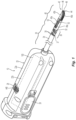
- a surgical instrument 10 provided in accordance with the present disclosure generally includes a housing 20, a shaft 30 extending distally from housing 20, an end effector assembly 40 extending distally from shaft 30, and an actuation assembly 100 disposed within housing 20 and operably associated with shaft 30 and end effector assembly 40.
- Instrument 10 is detailed herein as an articulating electrosurgical forceps configured for use with a robotic surgical system, e.g., robotic surgical system 500 ( FIG. 3 ).
- robotic surgical system 500 FIG. 3
- the aspects and features of instrument 10 provided in accordance with the present disclosure, detailed below, are equally applicable for use with other suitable surgical instruments (including non-robotic surgical instrument) and/or in other suitable surgical systems (including non-robotic surgical systems).
- Housing 20 of instrument 10 includes first and second body portion 22a, 22b and a proximal face plate 24 ( FIG. 2 ) that cooperate to enclose actuation assembly 100 therein.
- Proximal face plate 24 includes apertures defined therein through which inputs 110-140 of actuation assembly 100 extend.
- a pair of latch levers 26 (only one of which is illustrated in FIG. 1 ) extend outwardly from opposing sides of housing 20 and enables releasable engagement (directly or indirectly) of housing 20 with a robotic arm of a surgical system, e.g., robotic surgical system 500 ( FIG. 3 ).
- An aperture 28 defined through housing 20 permits thumbwheel 440 to extend therethrough to enable manual manipulation of thumbwheel 440 from the exterior of housing 20 to permit manual opening and closing of end effector assembly 40.
- Shaft 30 of instrument 10 includes a distal segment 32, a proximal segment 34, and an articulating section 36 disposed between the distal and proximal segments 32, 34, respectively.
- Articulating section 36 includes one or more articulating components 37, e.g., links, joints, etc.
- a plurality of articulation cables 38 e.g., four (4) articulation cables, or other suitable actuators, extends through articulating section 36.
- articulation cables 38 are operably coupled to distal segment 32 of shaft 30 at the distal ends thereof and extend proximally from distal segment 32 of shaft 30, through articulating section 36 of shaft 30 and proximal segment 34 of shaft 30, and into housing 20, wherein articulation cables 38 operably couple with an articulation assembly 200 of actuation assembly 100 to enable selective articulation of distal segment 32 (and, thus end effector assembly 40) relative to proximal segment 34 and housing 20, e.g., about at least two axes of articulation (yaw and pitch articulation, for example).
- Articulation cables 38 are arranged in a generally rectangular configuration, although other suitable configurations are also contemplated.
- actuation of articulation cables 38 is effected in pairs. More specifically, in order to pitch end effector assembly 40, the upper pair of cables 38 is actuated in a similar manner while the lower pair of cables 38 is actuated in a similar manner relative to one another but an opposite manner relative to the upper pair of cables 38. With respect to yaw articulation, the right pair of cables 38 is actuated in a similar manner while the left pair of cables 38 is actuated in a similar manner relative to one another but an opposite manner relative to the right pair of cables 38.
- Distal segment 32 of shaft 30 defines a clevis portion of end effector assembly 40 that supports first and second jaw members 42, 44, respectively.
- Each jaw member 42, 44 includes a proximal extension portion 43a, 45a and a distal body portion 43b, 45b, respectively.
- Distal body portions 43b, 45b define opposed tissue-contacting surfaces 46, 48, respectively.
- Proximal extension portions 43a, 45a are pivotably coupled to one another about a pivot pin 50 and are operably coupled to one another via a cam drive mechanism 52 (described in greater detail below) to enable pivoting of jaw member 42 relative to jaw member 44 and distal segment 32 of shaft 30 between a spaced-apart position (e.g., an open position of end effector assembly 40) and an approximated position (e.g., a closed position of end effector assembly 40) for grasping tissue between tissue-contacting surfaces 46, 48.
- a bilateral configuration may be provided whereby both jaw members 42, 44 are pivotable relative to one another and distal segment 32 of shaft 30.
- Opposing longitudinally-extending channels are defined through tissue-contacting surfaces 46, 48, respectively, of jaw members 42, 44.
- a translating cutting element (not shown) is provided and selectively advanceable to enable cutting of tissue grasped between tissue-contacting surfaces 46, 48 of jaw members 42, 44, respectively.
- a cutting drive assembly 300 ( FIG. 2 ) of actuation assembly 100 provides for selective actuation of cutting element through channel(s) of jaw members 42, 44 to cut tissue grasped between tissue-contacting surfaces 46, 48.
- Cutting drive assembly 300 is operably coupled to third input 130 of actuation assembly 100 such that, upon receipt of appropriate rotational input into third input 130, cutting drive assembly 300 advances the cutting element between jaw members 42, 44 to cut tissue grasped between tissue-contacting surfaces 46, 48.
- a drive rod (not shown) is operably coupled to end effector assembly 40 such that longitudinal actuation of drive rod pivots jaw member 42 relative to jaw member 44 between the spaced-apart and approximated positions, as detailed below. More specifically, urging drive rod proximally pivots jaw member 42 relative to jaw member 44 towards the approximated position while urging drive rod distally pivots jaw member 42 relative to jaw member 44 towards the spaced-apart position.
- the reverse configuration is also contemplated.
- Drive rod extends proximally from end effector assembly 40 through shaft 30 and into housing 20 wherein drive rod is operably coupled with a jaw drive assembly 400 of actuation assembly 100 to enable selective actuation of end effector assembly 40 to grasp tissue therebetween and apply a closure force within an appropriate jaw closure force range, e.g., in response to an appropriate rotational input into fourth input 140.
- Tissue-contacting surfaces 46, 48 of jaw members 42, 44, respectively are at least partially formed from an electrically conductive material and are energizable to different potentials to enable the conduction of electrical energy through tissue grasped therebetween, although tissue-contacting surfaces 46, 48 may alternatively be configured to supply any suitable energy, e.g., thermal, microwave, light, ultrasonic, etc., through tissue grasped therebetween for energy-based tissue treatment.
- tissue-contacting surfaces 46, 48 may alternatively be configured to supply any suitable energy, e.g., thermal, microwave, light, ultrasonic, etc., through tissue grasped therebetween for energy-based tissue treatment.
- Instrument 10 defines conductive pathways extending through housing 20 and shaft 30 to end effector assembly 40 that may include lead wires, contacts, and/or electrically-conductive components to enable electrical connection of tissue-contacting surfaces 46, 48 of jaw members 42, 44, respectively, to an energy source (not shown), e.g., an electrosurgical generator via an electrosurgical cable extending therebetween, for supplying energy to tissue-contacting surfaces 46, 48 to treat, e.g., seal, tissue grasped between tissue-contacting surfaces 46, 48.
- an energy source e.g., an electrosurgical generator via an electrosurgical cable extending therebetween
- Actuation assembly 100 is disposed within housing 20 and includes articulation assembly 200, cutting drive assembly 300, and jaw drive assembly 400.
- Articulation assembly 200 is operably coupled between first and second inputs 110, 120, respectively, of actuation assembly 100 and articulation cables 38 such that, upon receipt of appropriate rotational inputs into first and/or second inputs 110, 120, articulation assembly 200 manipulates cables 38 ( FIG. 1 ) to articulate end effector assembly 40 in a desired direction, e.g., to pitch and/or yaw end effector assembly 40.
- Cutting drive assembly 300 as noted above, enables reciprocation of the cutting element between jaw members 42, 44 to cut tissue grasped between tissue-contacting surfaces 46, 48 in response to receipt of appropriate rotational input into third input 130.
- Jaw drive assembly 400 is operably coupled between fourth input 140 of actuation assembly 100 and drive rod such that, upon receipt of appropriate rotational input into fourth input 140, jaw drive assembly 400 pivots jaw members 42, 44 between the spaced-apart and approximated positions to grasp tissue therebetween and apply a closure force within an appropriate closure force range.
- Actuation assembly 100 is configured to operably interface with a robotic surgical system 500 ( FIG. 3 ) when instrument 10 is mounted on robotic surgical system 500 ( FIG. 3 ), to enable robotic operation of actuation assembly 100 to provide the above-detailed functionality. That is, robotic surgical system 500 ( FIG. 3 ) selectively provides rotational inputs to inputs 110-140 of actuation assembly 100 to articulate end effector assembly 40, grasp tissue between jaw members 42, 44, and/or cut tissue grasped between jaw members 42, 44.
- actuation assembly 100 be configured to interface with any other suitable surgical system, e.g., a manual surgical handle, a powered surgical handle, etc.
- robotic surgical system 500 FIG. 3
- robotic surgical system 500 is generally described.
- FIG. 3 a schematic representation of a robotic surgical system 500 is configured for use in accordance with the present disclosure. Aspects and features of robotic surgical system 500 not germane to the understanding of the present disclosure are omitted to avoid obscuring the aspects and features of the present disclosure in unnecessary detail.
- Robotic surgical system 500 generally includes a plurality of robot arms 502, 503; a control device 504; and an operating console 505 coupled with control device 504.
- Operating console 505 may include a display device 506, which may be set up in particular to display three-dimensional images; and manual input devices or handles 507, 508, by means of which a person, e.g., a surgeon, may be able to telemanipulate robot arms 502, 503 in a first operating mode.
- Robotic surgical system 500 may be configured for use on a patient 513 lying on a patient table 512 to be treated in a minimally invasive manner.
- Robotic surgical system 500 may further include a database 514, in particular coupled to control device 504, in which are stored, for example, pre-operative data from patient 513 and/or anatomical atlases.
- Each of the robot arms 502, 503 may include a plurality of members, which are connected through joints, and a mounted device which may be, for example, a surgical tool "ST.”
- a surgical tool "ST” may be instrument 10 ( FIG. 1 ), thus providing such functionality on a robotic surgical system 500.
- Robot arms 502, 503 may be driven by electric drives, e.g., motors, connected to control device 504.
- Control device 504 e.g., a computer
- Control device 504 may be configured to activate the motors, in particular by means of a computer program, in such a way that robot arms 502, 503, and, thus, their mounted surgical tools "ST" execute a desired movement and/or function according to a corresponding input from manual input devices 507, 508, respectively.
- Control device 504 may also be configured in such a way that it regulates the movement of robot arms 502, 503 and/or of the motors.
- FIGS. 4A and 4B portions of the operating console 505 are depicted in more detail, namely, input devices or handles 507, 508.
- Each input device or handle 507, 508 includes similar components and, as such, only input device or handle 508 is depicted in FIG. 4B .
- Input device 508 includes a housing 520 defining a cavity 521 therein configured to house an actuation assembly 550 configured to communicate with one or more of the inputs 110-140 described in detail above.
- Housing 520 may be coupled to one or more gimbal mechanisms 540a-540c to control the extension, rotation, articulation, et. al. of the end effector assembly 40 as described above.
- Actuation assembly 550 is operatively coupled to a lever 530 which, upon actuation thereof relative to housing 520, opens and closes jaw members 42, 44 of end effector assembly 40. More particularly, lever 530 couples to a series of components, e.g., links, couplers, and/or actuators 551-555, configured for communication with input 140 for controlling the closure of jaw members 42, 44 relative to one another as described above. Although depicted as a series of links, couplers and/or actuators 551-555, any type of mechanical or electromechanical arrangement is contemplated. Moreover, and as explained below, actuation of lever 530 relative to the actuation of the jaw members 42, 44 may be linear 1:1, non-linear 1:2 or variable during the entire range of movement or stroke of the lever 530.
- actuation of lever 530 relative to the actuation of the jaw members 42, 44 may be linear 1:1, non-linear 1:2 or variable during the entire range of movement or stroke of the lever 530.
- Lever 530 includes a finger support 535 which is configured to facilitate relative movement of the lever 530 to the housing 520. More particularly, finger support 535 may be cuff-like to envelop one or more fingers of the user to promote retraction of the lever 530 away from the housing 520 and facilitate rotation of the housing about one or more of the above-identified gimbal mechanisms 540a-540c.
- the actuation of the jaw members 42, 44 is controlled through motor rotations which are mapped to the actuation lever 530. Since the forces required to generate a proper seal are typically on the order of 100 psi or greater, the software maps the relative movement of the surgeon's fingers and lever 530 to the housing 520 and correlates this relative movement to the jaw members 42, 44. Various software algorithms are utilized for this purpose. As a result, very little force is required to move the lever 530 relative to the housing 520 via the surgeon's fingers to generate the proper pressure for sealing tissue. This also helps to offset surgical fatigue.
- the robotic sealer is designed to generate sealing pressures at the jaw members 42, 44 with far less comparative forces at the lever 530, in some instances too much pressure, e.g., pressures associated with sealing tissue, may be applied to a vessel or tissue bundle when the surgeon's intention is to simply grasp, manipulate or cut tissue.
- FIGS. 5A and 5B show one embodiment of an input device or handle 608 in accordance with the present disclosure which includes a variable-force lever 630 configured to allow grasping, manipulation and cutting when moved to a first position and configured to generate the requisite pressure between the jaw members 42, 44 when moved to a second position for sealing vessels and tissue.
- Input device 608 includes a variable force lever 630 having various mechanical, electromechanical or other features (e.g., software) that are configured regulate and correlate the relative motion of the lever 630 with the motion of the jaw members 42, 44. More particularly and as shown in FIG.
- initial movement of lever 630 from an unactuated position or home position "H” towards a grasp position "G” actuates one or both of the jaw members 42, 44 to grasp a vessel or tissue with a first pressure known to avoid structural damage to sensitive tissue.
- Pressures in the range of about 0.01 Kg/cm 2 to about 2 kg/cm 2 are contemplated. Pressures up to and including the lower range of the below-identified sealing pressure range are also contemplated.
- the force on the handle may be linear, e.g., the same amount of force through the entire range of motion from position "H” to position "G", or may be non-linear, e.g., the amount of force varies within the above-identified range through the range of motion from position "H" to position "G".
- the surgeon can remotely actuate the jaw members 42, 44 to manipulate, grasp and cut (e.g., without a seal if applicable) vessels and tissue by continually moving the lever 630 between positions "H" and position "G” without any concern of applying too much force to vessels or tissue. Vessels or tissue may also be dissected when moving the lever from position "G” to position "H", e.g., poke and spread dissection.
- the surgeon may opt to seal the vessel or tissue between the jaw members 42, 44.
- the surgeon moves the lever 630 closer the housing 620, e.g., from position "G” to position “S” which, in turn, generates additional forces between the jaw members 42, 44 to enable sealing once the robotic sealer 10 is activated via one or more activation buttons 525 ( FIG. 4A ). Forces within the range of about 3 kg/cm 2 to about 16 kg/cm 2 are contemplated for sealing purposes.
- a switch or other safety feature 632 may be operably associated with the lever 630 and employed to switch the lever 630 between modes or reposition or add mechanical or electromechanical components 650 to change the applied forces from the lever 630 to the jaw members 42, 44.
- the components 650 may be disposed in a cavity 621 defined in the housing 620 and may be arranged to provide resistance to the lever 630 correlating to the resistance of the tissue disposed between the jaw members 42, 44.
- Lever 630 includes a finger support 635 which is configured to facilitate relative movement of the lever 630 to the housing 620. More particularly, finger support 635 may be cuff-like to envelop one or more fingers of the user to the promote retraction of the lever 630 away from the housing 620 and facilitate rotation of the housing about one or more of the above-identified gimbal mechanisms, e.g., gimbal mechanisms 540a-540c of FIG. 4A .
- FIG. 6 another embodiment of a handle 708 is envisioned which adjusts the haptic feedback of the lever 730 based on empirical data such that each lever stroke continues from a fully open position, through a typical grasping position and to a position for sealing tissue. More particularly, point “A" position on the lever 730 indicates a fully open position wherein the jaw members 42, 44 are fully open to orient tissue therebetween. Between point “A” and point “B", with the lever 730 starting to close, there is only a slight haptic force associated with the lever 730, e.g., very little resistance on the lever 730.
- Point “B” may be customizable depending on the particular instrument or based on empirical data, e.g., point “B” is configured on the lever 730 as the point between a large vessel disposed within the jaws 42, 44 and nothing in the jaws 42, 44. In other instances, point “B” may be customizable based on the feedback from sensors or torque.
- the lever 730 begins to compress a spring (or some other pressure control mechanism (not shown)) which will provide direct haptic feedback to the surgeon regarding pressure between jaw members 42, 44.
- the lever 730 and spring relationship may be linear or exponential or may be a combination, e.g., initially linear and then exponential.
- moving the lever between points “B” and “C” may induce a pressure within the above-identified sealing range and the surgeon may opt to seal tissue based on perceived haptic feedback within this stroke range.
- a point "C" may be included within the lever stroke that definitively identifies that the jaw pressure is within the sealing range.
- any further movement of the lever 730 does not increase the pressure between the jaw members 42, 44, e.g., the pressure is offloaded by the spring (or some other pressure control mechanism (not shown)) to not over-compress the tissue.
- Point “D” may be included as a bottom out point of the lever 730.
- any combination of mechanical components, electromechanical components, software, etc. may be utilized to map or correlate the various positions of the lever 630 to the input 140 which, in turn, controls the relative movement of the jaw members 42, 44.
- the relationship of the lever 630 to the movement of the jaw members 42, 44 may be linear or non-linear depending upon a particular purpose.
- the lever 630 may be coupled to one or more mechanical, electromechanical components, e.g., components 551-555 ( FIG. 4B ), or software, that are configured to vary the actuation force (either linearly or non-linearly) as the lever 630 is actuated relative to housing 620 simulating the "feel" of the jaw members 42, 44 grasping, manipulating or sealing vessels or tissue.
- a visual signal e.g., a series of LEDs or the like or varying colors
- audible tone generally represented by component 545 of robotic system 500 ( FIG. 3 )
- a visual signal e.g., a series of LEDs or the like or varying colors
- audible tone generally represented by component 545 of robotic system 500 ( FIG. 3 )
- the force on the lever 630 is correlated to the closure pressure between the jaw members 42, 44 based on the position of the lever 630 relative to the housing 620.
- the resistance on the lever 630 may be related to the internal mechanical or electromechanical components 551-555 ( FIG. 4B ) or may be based on software associated with one or more of the components or input 140. In this instance, there is no reliance on a sensor providing feedback to the components 551-555 or software to alter or otherwise effect the resistance on the level 630.
- various visual or audible feedback 545 may be conveyed to the surgeon relating to the amount of pressure between the jaw members 42, 44.
- the feedback may be as simple as a "SAFE" signal for manipulation, e.g., green light, safe tone, or may be metered in relation to the amount of pressure being applied to tissue and when a pressure is being applied to warrant sealing, e.g., "SEAL" signal.
- SAFE simple as a "SAFE” signal for manipulation, e.g., green light, safe tone
- SEAL e.g., "SEAL” signal
- the handle 608, robotic controller 505, robotic sealer 10, or the software associated with one or more of the foregoing may be configured to switch the relative motion of the lever 630 and the resulting closure pressure associated with the jaw members 42, 44 based on user selection. More particularly, in a first instance or with a first user selection, e.g., grasping, manipulation, cutting or dissection mode, actuation of the lever 630 may ramp from the jaw members 42, 44 being spaced from one another (e.g., zero closure force between jaw members 42, 44) to a correlating pressure between the jaw members 42, 44 within a range of about 0.1 kg/cm 2 to about 2 kg/cm 2 . Other pressure ranges for grasping, manipulation, cutting or dissection are envisioned. The relationship of the lever 630 force to the jaw member 42, 44 closure pressure may be linear or non-linear within this range.
- actuation of the lever 630 may ramp from the jaw members 42, 44 being spaced from one another to a correlating pressure between the jaw members 42, 44 within a range of about 3 kg/cm 2 to about 16 kg/cm 2 .
- the relationship of the lever 630 force to the jaw member 42, 44 sealing pressure may be linear or non-linear within this range.
- Various audible or visual safety measures 545 may be employed with the handle 608 or robotic surgical system 500 to alert the user of the current disposition of the lever 630 and which pressure will be applied to the jaw members 42, 44 upon actuation thereof.
- Various safety measures may be employed using one or more mechanical, electromechanical or software that would only allow a sealing pressure to be delivered when energy is being applied. For example, a slight delay may be programmed into the control software to delay activation of electrosurgical energy until a proper jaw pressure is applied between the jaw members 42, 44 via the lever 630.
Landscapes
- Health & Medical Sciences (AREA)
- Engineering & Computer Science (AREA)
- Surgery (AREA)
- Life Sciences & Earth Sciences (AREA)
- Medical Informatics (AREA)
- General Health & Medical Sciences (AREA)
- Biomedical Technology (AREA)
- Heart & Thoracic Surgery (AREA)
- Nuclear Medicine, Radiotherapy & Molecular Imaging (AREA)
- Molecular Biology (AREA)
- Animal Behavior & Ethology (AREA)
- Veterinary Medicine (AREA)
- Public Health (AREA)
- Robotics (AREA)
- Physics & Mathematics (AREA)
- Plasma & Fusion (AREA)
- Otolaryngology (AREA)
- Manipulator (AREA)
- Surgical Instruments (AREA)
Abstract
A robotic system includes an electrosurgical instrument having an instrument housing having a shaft with an end effector assembly and first and second jaw members attached thereto movable to grasp tissue. An input is operably coupled to the instrument housing to move the jaw members. A handle is remotely disposed relative to the instrument housing and is configured to communicate with the input, the handle having a lever configured to cooperate with the input to control the jaw members relative to movement of the lever. The lever moves between a homing position and a first position correlating to the jaw members closing with a pressure therebetween of about 0.1 kg/cm<sup>2</sup> to about 2 kg/cm<sup>2</sup>. The lever further movable to a seal position correlating to the jaw members closing about tissue with a pressure between about 3 kg/cm<sup>2</sup> to about 16 kg/cm<sup>2</sup> for sealing.
Description
- The present disclosure relates to surgical instruments and, more specifically, to end effector drive mechanisms for surgical instruments such as for use in robotic surgical systems.
- Robotic surgical systems are increasingly utilized in various different surgical procedures. Some robotic surgical systems include a console supporting a robotic arm. One or more different surgical instruments may be configured for use with the robotic surgical system and selectively mountable to the robotic arm. The robotic arm provides one or more inputs to the mounted surgical instrument to enable operation of the mounted surgical instrument.
- A surgical forceps, one type of instrument capable of being utilized with a robotic surgical system, relies on mechanical action between its jaw members to grasp, clamp, and constrict tissue. Electrosurgical forceps utilize both mechanical clamping action and energy to heat tissue to treat, e.g., coagulate, cauterize, or seal, tissue. Typically, once tissue is treated, the tissue is severed using a cutting element. Accordingly, electrosurgical forceps are designed to incorporate a cutting element to effectively sever treated tissue. Alternatively, energy-based, e.g., thermal, electrical, ultrasonic, etc., cutting mechanisms may be implemented.
- With traditional surgical instrumentation, e.g., open and endoscopic surgical instrumentation, the surgeon is typically able to feel or otherwise sense direct feedback from the end effector relating to the size of the tissue between the jaw members as well as the force being applied during manipulation and sealing. With robotic instrumentation, haptic feedback may be lost or sacrificed for ease of use to offset among other things, surgical fatigue.
- As used herein, the term "distal" refers to the portion that is being described which is farther from an operator (whether a human surgeon or a surgical robot), while the term "proximal" refers to the portion that is being described which is closer to the operator. The terms "about," substantially," and the like, as utilized herein, are meant to account for manufacturing, material, environmental, use, and/or measurement tolerances and variations, and in any event may encompass differences of up to 10%. Further, to the extent consistent, any of the aspects described herein may be used in conjunction with any or all of the other aspects described herein.
- Provided in accordance with aspects of the present disclosure is a robotic surgical system including an electrosurgical instrument including an instrument housing having a shaft extending therefrom. An end effector assembly is disposed at a distal end of the shaft and includes first and second jaw members movable between a first position wherein one or both of the jaw members is spaced relative to the other of the jaw members and a second position wherein the first and second jaw members cooperate to grasp tissue. An input is operably coupled to the instrument housing and is configured to move the jaw members between the first and second positions. One or more handles is remotely disposed relative to the instrument housing and is configured to communicate with the input for controlling the jaw members. The handle includes a housing having a lever operably coupled thereto, the lever, in turn, is configured to cooperate with the input to control the movement of the jaw members relative to movement of the lever. The lever is moveable between a homing position wherein the lever is spaced relative to the housing and the correlating jaw members are disposed in the first position and a grasp position wherein the lever is closer to the housing and the correlating jaw members are closed about tissue with a pressure between the jaw members in the range of about 0.1 kg/cm2 to about 2 kg/cm2. The lever is also movable between the grasp position and a seal position wherein the lever is closer to the housing and the correlating jaw members are closed about tissue with a pressure between the jaw members in the range of about 3 kg/cm2 to about 16 kg/cm2 for sealing tissue between the jaw members upon activation of electrosurgical energy.
- In aspects according to the present disclosure, the housing of the one handle includes a cavity defined therein configured to house one or more components therein configured to operably connect to the input such that movement of the lever relative to the housing correlates to movement of the jaw members between the first and second positions.
- In aspects according to the present disclosure, the correlation of movement of the lever and the jaw members is linear. In other aspects according to the present disclosure, the correlation of movement of the lever and the jaw members is non-linear.
- In aspects according to the present disclosure, the combination of components disposed in the cavity correlate the actuation force of the lever to the applied closure pressure between the jaw members with tissue engaged therebetween. In aspects according to the present disclosure, the combination of components disposed in the cavity include levers, gears, linkages, and springs.
- Provided in accordance with aspects of the present disclosure is a robotic surgical system including an electrosurgical instrument including an instrument housing having a shaft extending therefrom. An end effector assembly is disposed at a distal end of the shaft and includes first and second jaw members movable between a first position wherein one or both of the jaw members is spaced relative to the other of the jaw members and a second position wherein the first and second jaw members cooperate to grasp tissue. An input is operably coupled to the instrument housing and is configured to move the jaw members between the first and second positions. One or more handles is remotely disposed relative to the instrument housing and configured to communicate with the input for controlling the jaw members. The handle includes a housing having a lever operably coupled thereto. The lever, upon movement thereof, cooperates with the input to impart movement of the jaw members between the first and second positions wherein initial movement of the lever from an unactuated position to a first position imparts movement to the jaw members with a closure pressure within the range of about 0.1 kg/cm2 to about 2 kg/cm2 and wherein subsequent movement of the lever beyond the first position imparts movement to the jaw members with a closure pressure within the range of about 3 kg/cm2 to about 16 kg/cm2.
- In aspects according to the present disclosure, the housing of the handle includes a cavity defined therein configured to house one or more components therein configured to operably connect to the input such that movement of the lever relative to the housing correlates to movement of the jaw members between the first and second positions.
- In aspects according to the present disclosure, the correlation of movement of the lever and the jaw members is linear. In other aspects according to the present disclosure, the correlation of movement of the lever and the jaw members is non-linear.
- In aspects according to the present disclosure, the combination of components disposed in the cavity correlate the actuation force of the lever to the applied pressure between the jaw members with tissue engaged therebetween. In other aspects according to the present disclosure, the combination of components disposed in the cavity include levers, gears, linkages, and springs.
- In aspects according to the present disclosure, the system further includes a tactile, visual and/or audible indicator operably associated with the lever configured to alert the user when the lever is moved beyond the first position.
- Provided in accordance with aspects of the present disclosure is a robotic surgical system including an electrosurgical instrument including an instrument housing having a shaft extending therefrom. An end effector assembly is disposed at a distal end of the shaft and includes first and second jaw members movable between a first position wherein one or both of the jaw members is spaced relative to the other of the jaw members and a second position wherein the first and second jaw members cooperate to grasp tissue. An input is operably coupled to the instrument housing and is configured to move the jaw members between the first and second positions. One or more handles is remotely disposed relative to the instrument housing and configured to communicate with the input for controlling the jaw members. The handle includes: a housing having a lever operably coupled thereto; and a switch operably disposed on one or both of the levers or the housing. The switch is moveable between a first position where the lever, upon movement thereof, cooperates with the input to impart movement to the jaw members between the first and second positions with a closure pressure within the range of about 0.1 kg/cm2 to about 2 kg/cm2 and a second position wherein movement of the lever imparts movement to the jaw members with a closure pressure within the range of about 3 kg/cm2 to about 16 kg/cm2.
- In aspects according to the present disclosure, movement of the switch to the second position configures the jaw members for electrosurgical activation. In other aspects according to the present disclosure, when the switch is disposed in the first position, electrosurgical energy is deactivated.
- In aspects according to the present disclosure, the system further includes a tactile, visual and/or audible indicator of the closure pressure between the jaw members.
- Various aspects and features of the present disclosure are described hereinbelow with reference to the drawings wherein:
-
FIG. 1 is a perspective view of a surgical instrument in accordance with the present disclosure configured for mounting on a robotic arm of a robotic surgical system; -
FIG. 2 is a rear perspective view of a proximal portion of the surgical instrument ofFIG. 1 with an outer housing removed; -
FIG. 3 is a schematic illustration of an exemplary robotic surgical system configured to releasably receive the surgical instrument ofFIG. 1 ; -
FIG. 4A is a top perspective view of the robotic surgical system ofFIG. 3 showing a pair of operating handles for remotely controlling the surgical instrument; -
FIG. 4B is an enlarged view of one of the operating handles of the robotic surgical system ofFIG. 4A ; -
FIG. 5A is an enlarged view of one of the operating handles in accordance with another embodiment of the present disclosure; -
FIG. 5B is an enlarged view of one of the operating handles in accordance with yet another embodiment of the present disclosure; and -
FIG. 6 is an enlarged view of the operating handles in accordance with still another embodiment of the present disclosure - Referring to
FIGS. 1 and2 , asurgical instrument 10 provided in accordance with the present disclosure generally includes ahousing 20, ashaft 30 extending distally fromhousing 20, anend effector assembly 40 extending distally fromshaft 30, and anactuation assembly 100 disposed withinhousing 20 and operably associated withshaft 30 andend effector assembly 40.Instrument 10 is detailed herein as an articulating electrosurgical forceps configured for use with a robotic surgical system, e.g., robotic surgical system 500 (FIG. 3 ). However, the aspects and features ofinstrument 10 provided in accordance with the present disclosure, detailed below, are equally applicable for use with other suitable surgical instruments (including non-robotic surgical instrument) and/or in other suitable surgical systems (including non-robotic surgical systems). -
Housing 20 ofinstrument 10 includes first andsecond body portion FIG. 2 ) that cooperate to encloseactuation assembly 100 therein.Proximal face plate 24 includes apertures defined therein through which inputs 110-140 ofactuation assembly 100 extend. A pair of latch levers 26 (only one of which is illustrated inFIG. 1 ) extend outwardly from opposing sides ofhousing 20 and enables releasable engagement (directly or indirectly) ofhousing 20 with a robotic arm of a surgical system, e.g., robotic surgical system 500 (FIG. 3 ). Anaperture 28 defined throughhousing 20 permits thumbwheel 440 to extend therethrough to enable manual manipulation ofthumbwheel 440 from the exterior ofhousing 20 to permit manual opening and closing ofend effector assembly 40. -
Shaft 30 ofinstrument 10 includes adistal segment 32, aproximal segment 34, and an articulatingsection 36 disposed between the distal andproximal segments section 36 includes one or more articulatingcomponents 37, e.g., links, joints, etc. A plurality ofarticulation cables 38, e.g., four (4) articulation cables, or other suitable actuators, extends through articulatingsection 36. More specifically,articulation cables 38 are operably coupled todistal segment 32 ofshaft 30 at the distal ends thereof and extend proximally fromdistal segment 32 ofshaft 30, through articulatingsection 36 ofshaft 30 andproximal segment 34 ofshaft 30, and intohousing 20, whereinarticulation cables 38 operably couple with anarticulation assembly 200 ofactuation assembly 100 to enable selective articulation of distal segment 32 (and, thus end effector assembly 40) relative toproximal segment 34 andhousing 20, e.g., about at least two axes of articulation (yaw and pitch articulation, for example).Articulation cables 38 are arranged in a generally rectangular configuration, although other suitable configurations are also contemplated. - With respect to articulation of
end effector assembly 40 relative toproximal segment 34 ofshaft 30, actuation ofarticulation cables 38 is effected in pairs. More specifically, in order to pitchend effector assembly 40, the upper pair ofcables 38 is actuated in a similar manner while the lower pair ofcables 38 is actuated in a similar manner relative to one another but an opposite manner relative to the upper pair ofcables 38. With respect to yaw articulation, the right pair ofcables 38 is actuated in a similar manner while the left pair ofcables 38 is actuated in a similar manner relative to one another but an opposite manner relative to the right pair ofcables 38. -
Distal segment 32 ofshaft 30 defines a clevis portion ofend effector assembly 40 that supports first andsecond jaw members jaw member proximal extension portion distal body portion Distal body portions surfaces Proximal extension portions pivot pin 50 and are operably coupled to one another via a cam drive mechanism 52 (described in greater detail below) to enable pivoting ofjaw member 42 relative tojaw member 44 anddistal segment 32 ofshaft 30 between a spaced-apart position (e.g., an open position of end effector assembly 40) and an approximated position (e.g., a closed position of end effector assembly 40) for grasping tissue between tissue-contactingsurfaces jaw members distal segment 32 ofshaft 30. - Opposing longitudinally-extending channels (not shown) are defined through tissue-contacting
surfaces jaw members surfaces jaw members FIG. 2 ) ofactuation assembly 100 provides for selective actuation of cutting element through channel(s) ofjaw members surfaces drive assembly 300 is operably coupled tothird input 130 ofactuation assembly 100 such that, upon receipt of appropriate rotational input intothird input 130, cuttingdrive assembly 300 advances the cutting element betweenjaw members surfaces - Continuing with reference to
FIGS. 1 and2 , a drive rod (not shown) is operably coupled to endeffector assembly 40 such that longitudinal actuation of drive rod pivotsjaw member 42 relative tojaw member 44 between the spaced-apart and approximated positions, as detailed below. More specifically, urging drive rod proximally pivotsjaw member 42 relative tojaw member 44 towards the approximated position while urging drive rod distally pivotsjaw member 42 relative tojaw member 44 towards the spaced-apart position. However, the reverse configuration is also contemplated. Drive rod extends proximally fromend effector assembly 40 throughshaft 30 and intohousing 20 wherein drive rod is operably coupled with ajaw drive assembly 400 ofactuation assembly 100 to enable selective actuation ofend effector assembly 40 to grasp tissue therebetween and apply a closure force within an appropriate jaw closure force range, e.g., in response to an appropriate rotational input intofourth input 140. - Tissue-contacting
surfaces jaw members surfaces Instrument 10 defines conductive pathways extending throughhousing 20 andshaft 30 to endeffector assembly 40 that may include lead wires, contacts, and/or electrically-conductive components to enable electrical connection of tissue-contactingsurfaces jaw members surfaces surfaces -
Actuation assembly 100 is disposed withinhousing 20 and includesarticulation assembly 200, cuttingdrive assembly 300, andjaw drive assembly 400.Articulation assembly 200 is operably coupled between first andsecond inputs actuation assembly 100 andarticulation cables 38 such that, upon receipt of appropriate rotational inputs into first and/orsecond inputs articulation assembly 200 manipulates cables 38 (FIG. 1 ) to articulateend effector assembly 40 in a desired direction, e.g., to pitch and/or yawend effector assembly 40. Cuttingdrive assembly 300, as noted above, enables reciprocation of the cutting element betweenjaw members surfaces third input 130.Jaw drive assembly 400 is operably coupled betweenfourth input 140 ofactuation assembly 100 and drive rod such that, upon receipt of appropriate rotational input intofourth input 140,jaw drive assembly 400 pivotsjaw members -
Actuation assembly 100 is configured to operably interface with a robotic surgical system 500 (FIG. 3 ) wheninstrument 10 is mounted on robotic surgical system 500 (FIG. 3 ), to enable robotic operation ofactuation assembly 100 to provide the above-detailed functionality. That is, robotic surgical system 500 (FIG. 3 ) selectively provides rotational inputs to inputs 110-140 ofactuation assembly 100 to articulateend effector assembly 40, grasp tissue betweenjaw members jaw members actuation assembly 100 be configured to interface with any other suitable surgical system, e.g., a manual surgical handle, a powered surgical handle, etc. For the purposes herein, robotic surgical system 500 (FIG. 3 ) is generally described. - Turning to
FIG. 3 , a schematic representation of a roboticsurgical system 500 is configured for use in accordance with the present disclosure. Aspects and features of roboticsurgical system 500 not germane to the understanding of the present disclosure are omitted to avoid obscuring the aspects and features of the present disclosure in unnecessary detail. - Robotic
surgical system 500 generally includes a plurality ofrobot arms control device 504; and anoperating console 505 coupled withcontrol device 504.Operating console 505 may include adisplay device 506, which may be set up in particular to display three-dimensional images; and manual input devices or handles 507, 508, by means of which a person, e.g., a surgeon, may be able to telemanipulaterobot arms surgical system 500 may be configured for use on apatient 513 lying on a patient table 512 to be treated in a minimally invasive manner. Roboticsurgical system 500 may further include adatabase 514, in particular coupled to controldevice 504, in which are stored, for example, pre-operative data frompatient 513 and/or anatomical atlases. - Each of the
robot arms FIG. 1 ), thus providing such functionality on a roboticsurgical system 500. -
Robot arms device 504.Control device 504, e.g., a computer, may be configured to activate the motors, in particular by means of a computer program, in such a way thatrobot arms manual input devices Control device 504 may also be configured in such a way that it regulates the movement ofrobot arms - Turning now to
FIGS. 4A and4B , portions of the operatingconsole 505 are depicted in more detail, namely, input devices or handles 507, 508. Each input device or handle 507, 508 includes similar components and, as such, only input device or handle 508 is depicted inFIG. 4B .Input device 508 includes ahousing 520 defining a cavity 521 therein configured to house anactuation assembly 550 configured to communicate with one or more of the inputs 110-140 described in detail above.Housing 520 may be coupled to one ormore gimbal mechanisms 540a-540c to control the extension, rotation, articulation, et. al. of theend effector assembly 40 as described above. Details relating to the various types of gimbal mechanisms that may be utilized for this purpose are disclosure inU.S. Patent Application Serial No. 16/306,420, filed November 30, 2018 -
Actuation assembly 550 is operatively coupled to alever 530 which, upon actuation thereof relative tohousing 520, opens and closesjaw members end effector assembly 40. More particularly, lever 530 couples to a series of components, e.g., links, couplers, and/or actuators 551-555, configured for communication withinput 140 for controlling the closure ofjaw members lever 530 relative to the actuation of thejaw members lever 530. -
Lever 530 includes afinger support 535 which is configured to facilitate relative movement of thelever 530 to thehousing 520. More particularly,finger support 535 may be cuff-like to envelop one or more fingers of the user to promote retraction of thelever 530 away from thehousing 520 and facilitate rotation of the housing about one or more of the above-identifiedgimbal mechanisms 540a-540c. - As mentioned above, during robotic surgery involving the sealing of vessels or tissue, it is important that the surgeon adequately control the pressure between the
jaw members jaw members jaw members housing 520 will actuate thejaw members - For example, with robotic vessel sealing devices such as those described above, the actuation of the
jaw members actuation lever 530. Since the forces required to generate a proper seal are typically on the order of 100 psi or greater, the software maps the relative movement of the surgeon's fingers and lever 530 to thehousing 520 and correlates this relative movement to thejaw members lever 530 relative to thehousing 520 via the surgeon's fingers to generate the proper pressure for sealing tissue. This also helps to offset surgical fatigue. However, since the robotic sealer is designed to generate sealing pressures at thejaw members lever 530, in some instances too much pressure, e.g., pressures associated with sealing tissue, may be applied to a vessel or tissue bundle when the surgeon's intention is to simply grasp, manipulate or cut tissue. -
FIGS. 5A and5B show one embodiment of an input device or handle 608 in accordance with the present disclosure which includes a variable-force lever 630 configured to allow grasping, manipulation and cutting when moved to a first position and configured to generate the requisite pressure between thejaw members Input device 608 includes avariable force lever 630 having various mechanical, electromechanical or other features (e.g., software) that are configured regulate and correlate the relative motion of thelever 630 with the motion of thejaw members FIG. 5A , initial movement oflever 630 from an unactuated position or home position "H" towards a grasp position "G" actuates one or both of thejaw members - As can be appreciated, the surgeon can remotely actuate the
jaw members lever 630 between positions "H" and position "G" without any concern of applying too much force to vessels or tissue. Vessels or tissue may also be dissected when moving the lever from position "G" to position "H", e.g., poke and spread dissection. - Once the vessel or tissue is properly grasped, the surgeon may opt to seal the vessel or tissue between the
jaw members lever 630 closer thehousing 620, e.g., from position "G" to position "S" which, in turn, generates additional forces between thejaw members robotic sealer 10 is activated via one or more activation buttons 525 (FIG. 4A ). Forces within the range of about 3 kg/cm2 to about 16 kg/cm2 are contemplated for sealing purposes. A switch orother safety feature 632 may be operably associated with thelever 630 and employed to switch thelever 630 between modes or reposition or add mechanical orelectromechanical components 650 to change the applied forces from thelever 630 to thejaw members components 650 may be disposed in acavity 621 defined in thehousing 620 and may be arranged to provide resistance to thelever 630 correlating to the resistance of the tissue disposed between thejaw members -
Lever 630 includes afinger support 635 which is configured to facilitate relative movement of thelever 630 to thehousing 620. More particularly,finger support 635 may be cuff-like to envelop one or more fingers of the user to the promote retraction of thelever 630 away from thehousing 620 and facilitate rotation of the housing about one or more of the above-identified gimbal mechanisms, e.g.,gimbal mechanisms 540a-540c ofFIG. 4A . - Turning briefly to
FIG. 6 , another embodiment of ahandle 708 is envisioned which adjusts the haptic feedback of thelever 730 based on empirical data such that each lever stroke continues from a fully open position, through a typical grasping position and to a position for sealing tissue. More particularly, point "A" position on thelever 730 indicates a fully open position wherein thejaw members lever 730 starting to close, there is only a slight haptic force associated with thelever 730, e.g., very little resistance on thelever 730. Point "B" may be customizable depending on the particular instrument or based on empirical data, e.g., point "B" is configured on thelever 730 as the point between a large vessel disposed within thejaws jaws - Between point "B" and point "C" the
lever 730 begins to compress a spring (or some other pressure control mechanism (not shown)) which will provide direct haptic feedback to the surgeon regarding pressure betweenjaw members lever 730 and spring relationship may be linear or exponential or may be a combination, e.g., initially linear and then exponential. In embodiments, moving the lever between points "B" and "C" may induce a pressure within the above-identified sealing range and the surgeon may opt to seal tissue based on perceived haptic feedback within this stroke range. Alternatively, a point "C" may be included within the lever stroke that definitively identifies that the jaw pressure is within the sealing range. Any further movement of thelever 730 does not increase the pressure between thejaw members lever 730. - It is contemplated that any combination of mechanical components, electromechanical components, software, etc. may be utilized to map or correlate the various positions of the
lever 630 to theinput 140 which, in turn, controls the relative movement of thejaw members lever 630 to the movement of thejaw members lever 630 may be coupled to one or more mechanical, electromechanical components, e.g., components 551-555 (FIG. 4B ), or software, that are configured to vary the actuation force (either linearly or non-linearly) as thelever 630 is actuated relative tohousing 620 simulating the "feel" of thejaw members component 545 of robotic system 500 (FIG. 3 )) may be used to represent the amount of pressure being applied to the vessel or tissue during the relative movement of thelevel 630. - As mentioned above, the force on the
lever 630 is correlated to the closure pressure between thejaw members lever 630 relative to thehousing 620. In embodiments, the resistance on thelever 630 may be related to the internal mechanical or electromechanical components 551-555 (FIG. 4B ) or may be based on software associated with one or more of the components orinput 140. In this instance, there is no reliance on a sensor providing feedback to the components 551-555 or software to alter or otherwise effect the resistance on thelevel 630. - As mentioned above, various visual or
audible feedback 545 may be conveyed to the surgeon relating to the amount of pressure between thejaw members jaw members - In one embodiment according to the present disclosure, the
handle 608,robotic controller 505,robotic sealer 10, or the software associated with one or more of the foregoing may be configured to switch the relative motion of thelever 630 and the resulting closure pressure associated with thejaw members lever 630 may ramp from thejaw members jaw members 42, 44) to a correlating pressure between thejaw members lever 630 force to thejaw member - In a next instance or with a second or different user selection, e.g., sealing, actuation of the
lever 630 may ramp from thejaw members jaw members lever 630 force to thejaw member visual safety measures 545 may be employed with thehandle 608 or roboticsurgical system 500 to alert the user of the current disposition of thelever 630 and which pressure will be applied to thejaw members - Various safety measures may be employed using one or more mechanical, electromechanical or software that would only allow a sealing pressure to be delivered when energy is being applied. For example, a slight delay may be programmed into the control software to delay activation of electrosurgical energy until a proper jaw pressure is applied between the
jaw members lever 630. - It will be understood that various modifications may be made to the aspects and features disclosed herein. Therefore, the above description should not be construed as limiting, but merely as exemplifications of various aspects and features. Those skilled in the art will envision other modifications within the scope and spirit of the claims appended thereto.
- The invention may be described by reference to the following numbered paragraphs:
- 1. A robotic surgical system, comprising: an electrosurgical instrument including an instrument housing having a shaft extending therefrom; an end effector assembly disposed at a distal end of the shaft, the end effector assembly including first and second jaw members movable between a first position wherein at least one of the jaw members is spaced relative to the other of the jaw members and a second position wherein the first and second jaw members cooperate to grasp tissue; an input operably coupled to the instrument housing and configured to move the jaw members between the first and second positions; at least one handle remotely disposed relative to the instrument housing and configured to communicate with the input for controlling the jaw members, the at least one handle including: a housing having a lever operably coupled thereto, the lever, in turn, configured to cooperate with the input to control the movement of the jaw members relative to movement of the lever, the lever moveable between a homing position wherein the lever is spaced relative to the housing and the correlating jaw members are disposed in the first position and a grasp position wherein the lever is closer to the housing and the correlating jaw members are closed about tissue with a pressure between the jaw members in the range of about 0.1 kg/cm2 to about 2 kg/cm2 and wherein the lever is movable between the grasp position and a seal position wherein the lever is closer to the housing and the correlating jaw members are closed about tissue with a pressure between the jaw members in the range of about 3 kg/cm2 to about 16 kg/cm2 for sealing tissue between the jaw members upon activation of electrosurgical energy.
- 2. The robotic surgical system according to
paragraph 1, wherein the housing of the at least one handle includes a cavity defined therein configured to house one or more components therein configured to operably connect to the input such that movement of the lever relative to the housing correlates to movement of the jaw members between the first and second positions. - 3. The robotic surgical system according to
paragraph 2, wherein the correlation of movement of the lever and the jaw members is linear. - 4. The robotic surgical system according to
paragraph 2, wherein the correlation of movement of the lever and the jaw members is non-linear. - 5. The robotic surgical system according to
paragraph 2, wherein the combination of components disposed in the cavity correlate the actuation force of the lever to the applied closure pressure between the jaw members with tissue engaged therebetween. - 6. The robotic surgical system according to paragraph 5, wherein the combination of components disposed in the cavity include levers, gears, linkages, and springs.
- 7. A robotic surgical system, comprising: an electrosurgical instrument including an instrument housing having a shaft extending therefrom; an end effector assembly disposed at a distal end of the shaft, the end effector assembly including first and second jaw members movable between a first position wherein at least one of the jaw members is spaced relative to the other of the jaw members and a second position wherein the first and second jaw members cooperate to grasp tissue; an input operably coupled to the instrument housing and configured to move the jaw members between the first and second positions; and at least one handle remotely disposed relative to the instrument housing and configured to communicate with the input for controlling the jaw members, the at least one handle including: a housing having a lever operably coupled thereto, the lever, upon movement thereof, cooperating with the input to impart movement of the jaw members between the first and second positions wherein initial movement of the lever from an unactuated position to a first position imparts movement to the jaw members with a closure pressure within the range of about 0.1 kg/cm2 to about 2 kg/cm2 and wherein subsequent movement of the lever beyond the first position imparts movement to the jaw members with a closure pressure within the range of about 3 kg/cm2 to about 16 kg/cm2.
- 8. The robotic surgical system according to paragraph 7, wherein the housing of the at least one handle includes a cavity defined therein configured to house one or more components therein configured to operably connect to the input such that movement of the lever relative to the housing correlates to movement of the jaw members between the first and second positions.
- 9. The robotic surgical system according to paragraph 8, wherein the correlation of movement of the lever and the jaw members is linear.
- 10. The robotic surgical system according to paragraph 8, wherein the correlation of movement of the lever and the jaw members is non-linear.
- 11. The robotic surgical system according to paragraph 8, wherein the combination of components disposed in the cavity correlate the actuation force of the lever to the applied pressure between the jaw members with tissue engaged therebetween.
- 12. The robotic surgical system according to paragraph 11, wherein the combination of components disposed in the cavity include levers, gears, linkages, and springs.
- 13. The robotic surgical system according to paragraph 7, further comprising at least one of a tactile, visual or audible indicator operably associated with the lever configured to alert the user when the lever is moved beyond the first position.
- 14. A robotic surgical system, comprising: an electrosurgical instrument including an instrument housing having a shaft extending therefrom; an end effector assembly disposed at a distal end of the shaft, the end effector assembly including first and second jaw members movable between a first position wherein at least one of the jaw members is spaced relative to the other of the jaw members and a second position wherein the first and second jaw members cooperate to grasp tissue; an input operably coupled to the instrument housing and configured to move the jaw members between the first and second positions; and at least one handle remotely disposed relative to the instrument housing and configured to communicate with the input for controlling the jaw members, the at least one handle including: a housing having a lever operably coupled thereto; a switch operably disposed on at least one of the lever or the housing, the switch moveable between a first position where the lever, upon movement thereof, cooperates with the input to impart movement to the jaw members between the first and second positions with a closure pressure within the range of about 0.1 kg/cm2 to about 2 kg/cm2 and a second position wherein movement of the lever imparts movement to the jaw members with a closure pressure within the range of about 3 kg/cm2 to about 16 kg/cm2.
- 15. The robotic surgical system according to paragraph 14, wherein movement of the switch to the second position configures the jaw members for electrosurgical activation.
- 16. The robotic surgical system according to paragraph 14, wherein when the switch is disposed in the first position, electrosurgical energy is deactivated.
- 17. The robotic surgical system according to paragraph 14, further comprising at least one of a tactile, visual or audible indicator of the closure pressure between the jaw members.
Claims (15)
- A robotic surgical system, comprising:an electrosurgical instrument including an instrument housing having a shaft extending therefrom;an end effector assembly disposed at a distal end of the shaft, the end effector assembly including first and second jaw members movable between a first position wherein at least one of the jaw members is spaced relative to the other of the jaw members and a second position wherein the first and second jaw members cooperate to grasp tissue;an input operably coupled to the instrument housing and configured to move the jaw members between the first and second positions;at least one handle remotely disposed relative to the instrument housing and configured to communicate with the input for controlling the jaw members, the at least one handle including:a housing having a lever operably coupled thereto, the lever, in turn, configured to cooperate with the input to control the movement of the jaw members relative to movement of the lever, the lever moveable between a homing position wherein the lever is spaced relative to the housing and the correlating jaw members are disposed in the first position and a grasp position wherein the lever is closer to the housing and the correlating jaw members are closed about tissue with a pressure between the jaw members in the range of about 0.1 kg/cm2 to about 2 kg/cm2 and whereinthe lever is movable between the grasp position and a seal position wherein the lever is closer to the housing and the correlating jaw members are closed about tissue with a pressure between the jaw members in the range of about 3 kg/cm2 to about 16 kg/cm2 for sealing tissue between the jaw members upon activation of electrosurgical energy.
- The robotic surgical system according to claim 1, wherein the housing of the at least one handle includes a cavity defined therein configured to house one or more components therein configured to operably connect to the input such that movement of the lever relative to the housing correlates to movement of the jaw members between the first and second positions.
- The robotic surgical system according to claim 2, wherein the correlation of movement of the lever and the jaw members is linear.
- The robotic surgical system according to claim 2, wherein the correlation of movement of the lever and the jaw members is non-linear.
- The robotic surgical system according to claim 2, 3 or 4, wherein the combination of components disposed in the cavity correlate the actuation force of the lever to the applied closure pressure between the jaw members with tissue engaged therebetween, preferably wherein the combination of components disposed in the cavity include levers, gears, linkages, and springs.
- A robotic surgical system, comprising:an electrosurgical instrument including an instrument housing having a shaft extending therefrom;an end effector assembly disposed at a distal end of the shaft, the end effector assembly including first and second jaw members movable between a first position wherein at least one of the jaw members is spaced relative to the other of the jaw members and a second position wherein the first and second jaw members cooperate to grasp tissue;an input operably coupled to the instrument housing and configured to move the jaw members between the first and second positions; andat least one handle remotely disposed relative to the instrument housing and configured to communicate with the input for controlling the jaw members, the at least one handle including:
a housing having a lever operably coupled thereto, the lever, upon movement thereof, cooperating with the input to impart movement of the jaw members between the first and second positions wherein initial movement of the lever from an unactuated position to a first position imparts movement to the jaw members with a closure pressure within the range of about 0.1 kg/cm2 to about 2 kg/cm2 and wherein subsequent movement of the lever beyond the first position imparts movement to the jaw members with a closure pressure within the range of about 3 kg/cm2 to about 16 kg/cm2. - The robotic surgical system according to claim 6, wherein the housing of the at least one handle includes a cavity defined therein configured to house one or more components therein configured to operably connect to the input such that movement of the lever relative to the housing correlates to movement of the jaw members between the first and second positions.
- The robotic surgical system according to claim 7, wherein the correlation of movement of the lever and the jaw members is linear.
- The robotic surgical system according to claim 7, wherein the correlation of movement of the lever and the jaw members is non-linear.
- The robotic surgical system according to claim 7, wherein the combination of components disposed in the cavity correlate the actuation force of the lever to the applied pressure between the jaw members with tissue engaged therebetween.
- The robotic surgical system according to claim 10, wherein the combination of components disposed in the cavity include levers, gears, linkages, and springs.
- The robotic surgical system according to any one of claims 6 to 11, further comprising at least one of a tactile, visual or audible indicator operably associated with the lever configured to alert the user when the lever is moved beyond the first position.
- A robotic surgical system, comprising:an electrosurgical instrument including an instrument housing having a shaft extending therefrom;an end effector assembly disposed at a distal end of the shaft, the end effector assembly including first and second jaw members movable between a first position wherein at least one of the jaw members is spaced relative to the other of the jaw members and a second position wherein the first and second jaw members cooperate to grasp tissue;an input operably coupled to the instrument housing and configured to move the jaw members between the first and second positions; andat least one handle remotely disposed relative to the instrument housing and configured to communicate with the input for controlling the jaw members, the at least one handle including:a housing having a lever operably coupled thereto;a switch operably disposed on at least one of the lever or the housing, the switch moveable between a first position where the lever, upon movement thereof, cooperates with the input to impart movement to the jaw members between the first and second positions with a closure pressure within the range of about 0.1 kg/cm2 to about 2 kg/cm2 and a second position wherein movement of the lever imparts movement to the jaw members with a closure pressure within the range of about 3 kg/cm2 to about 16 kg/cm2.
- The robotic surgical system according to claim 13, wherein movement of the switch to the second position configures the jaw members for electrosurgical activation preferably wherein when the switch is disposed in the first position, electrosurgical energy is deactivated.
- The robotic surgical system according to claim 14, further comprising at least one of a tactile, visual or audible indicator of the closure pressure between the jaw members.
Applications Claiming Priority (1)
| Application Number | Priority Date | Filing Date | Title |
|---|---|---|---|
| US17/403,491 US12611246B2 (en) | 2021-08-16 | 2021-08-16 | End effector drive mechanisms for surgical instruments such as for use in robotic surgical systems |
Publications (1)
| Publication Number | Publication Date |
|---|---|
| EP4137081A1 true EP4137081A1 (en) | 2023-02-22 |
Family
ID=82939761
Family Applications (1)
| Application Number | Title | Priority Date | Filing Date |
|---|---|---|---|
| EP22190423.8A Pending EP4137081A1 (en) | 2021-08-16 | 2022-08-15 | End effector drive mechanisms for surgical instruments such as for use in robotic surgical systems |
Country Status (4)
| Country | Link |
|---|---|
| US (1) | US12611246B2 (en) |
| EP (1) | EP4137081A1 (en) |
| JP (1) | JP2023027029A (en) |
| CN (1) | CN115919466A (en) |
Citations (5)
| Publication number | Priority date | Publication date | Assignee | Title |
|---|---|---|---|---|
| US20130103050A1 (en) * | 2011-10-21 | 2013-04-25 | Intuitive Surgical Operations, Inc. | Grip force control for robotic surgical instrument end effector |
| US20140074091A1 (en) * | 2012-09-07 | 2014-03-13 | Covidien Lp | Instruments, systems, and methods for sealing tissue structures |
| US20140107646A1 (en) * | 2005-08-19 | 2014-04-17 | Covidien Ag | Single action tissue sealer |
| US20170319228A1 (en) * | 2012-06-29 | 2017-11-09 | Ethicon Llc | Haptic feedback devices for surgical robot |
| US20200289191A1 (en) * | 2019-03-15 | 2020-09-17 | Covidien Lp | Surgical instrument with increased lever stroke |
Family Cites Families (52)
| Publication number | Priority date | Publication date | Assignee | Title |
|---|---|---|---|---|
| US5409453A (en) | 1992-08-12 | 1995-04-25 | Vidamed, Inc. | Steerable medical probe with stylets |
| US6731988B1 (en) * | 1992-01-21 | 2004-05-04 | Sri International | System and method for remote endoscopic surgery |
| US5752973A (en) | 1994-10-18 | 1998-05-19 | Archimedes Surgical, Inc. | Endoscopic surgical gripping instrument with universal joint jaw coupler |
| US5792135A (en) | 1996-05-20 | 1998-08-11 | Intuitive Surgical, Inc. | Articulated surgical instrument for performing minimally invasive surgery with enhanced dexterity and sensitivity |
| US7666191B2 (en) | 1996-12-12 | 2010-02-23 | Intuitive Surgical, Inc. | Robotic surgical system with sterile surgical adaptor |
| US7758569B2 (en) | 1998-02-24 | 2010-07-20 | Hansen Medical, Inc. | Interchangeable surgical instrument |
| US6659939B2 (en) | 1998-11-20 | 2003-12-09 | Intuitive Surgical, Inc. | Cooperative minimally invasive telesurgical system |
| US7048744B2 (en) | 2001-04-26 | 2006-05-23 | Sol Wiess | Attachable surgical accessory instrument |
| US6554829B2 (en) | 2001-01-24 | 2003-04-29 | Ethicon, Inc. | Electrosurgical instrument with minimally invasive jaws |
| US6817974B2 (en) | 2001-06-29 | 2004-11-16 | Intuitive Surgical, Inc. | Surgical tool having positively positionable tendon-actuated multi-disk wrist joint |
| US6602252B2 (en) | 2002-01-03 | 2003-08-05 | Starion Instruments Corporation | Combined dissecting, cauterizing, and stapling device |
| US6969385B2 (en) | 2002-05-01 | 2005-11-29 | Manuel Ricardo Moreyra | Wrist with decoupled motion transmission |
| US7857183B2 (en) | 2004-07-28 | 2010-12-28 | Ethicon Endo-Surgery, Inc. | Surgical instrument incorporating an electrically actuated articulation mechanism |
| US7143925B2 (en) | 2004-07-28 | 2006-12-05 | Ethicon Endo-Surgery, Inc. | Surgical instrument incorporating EAP blocking lockout mechanism |
| US7540872B2 (en) | 2004-09-21 | 2009-06-02 | Covidien Ag | Articulating bipolar electrosurgical instrument |
| DE112006000553B4 (en) | 2005-03-31 | 2015-11-05 | Thk Co., Ltd. | Thrust transfer device |
| US8579176B2 (en) | 2005-07-26 | 2013-11-12 | Ethicon Endo-Surgery, Inc. | Surgical stapling and cutting device and method for using the device |
| US8029531B2 (en) | 2006-07-11 | 2011-10-04 | Cambridge Endoscopic Devices, Inc. | Surgical instrument |
| WO2008045333A2 (en) | 2006-10-05 | 2008-04-17 | Tyco Healthcare Group Lp | Flexible endoscopic stitching devices |
| EP3097869B1 (en) | 2007-09-21 | 2020-03-11 | Covidien LP | Surgical device |
| US7861906B2 (en) | 2008-02-14 | 2011-01-04 | Ethicon Endo-Surgery, Inc. | Surgical stapling apparatus with articulatable components |
| US8858547B2 (en) | 2009-03-05 | 2014-10-14 | Intuitive Surgical Operations, Inc. | Cut and seal instrument |
| US9820806B2 (en) * | 2009-09-29 | 2017-11-21 | Covidien Lp | Switch assembly for electrosurgical instrument |
| CN102596087B (en) | 2009-11-13 | 2015-07-22 | 直观外科手术操作公司 | Motor interface for parallel drive shafts within an independently rotating member |
| US20110118708A1 (en) | 2009-11-13 | 2011-05-19 | Intuitive Surgical Operations, Inc. | Double universal joint |
| EP2594222B1 (en) | 2009-11-13 | 2018-10-03 | Intuitive Surgical Operations, Inc. | Surgical tool with a compact wrist |
| JP6518403B2 (en) | 2011-02-18 | 2019-05-22 | インテュイティブ サージカル オペレーションズ, インコーポレイテッド | Fusion and cutting surgical instruments and related methods |
| US8700822B2 (en) | 2011-07-08 | 2014-04-15 | Hewlett-Packard Development Company, L.P. | Parallel aggregation system |
| US8968312B2 (en) | 2011-11-16 | 2015-03-03 | Covidien Lp | Surgical device with powered articulation wrist rotation |
| US9737300B2 (en) | 2013-03-13 | 2017-08-22 | Ethicon Llc | Electrosurgical device with disposable shaft having rack and pinion drive |
| KR101584766B1 (en) | 2014-04-24 | 2016-01-12 | 주식회사 리브스메드 | Surgical instrument |
| EP3142592A4 (en) | 2014-05-13 | 2018-01-03 | Covidien LP | Robotic surgical systems and instrument drive units |
| WO2016043845A1 (en) | 2014-09-15 | 2016-03-24 | Covidien Lp | Robotically controlling surgical assemblies |
| WO2016137611A1 (en) | 2015-02-26 | 2016-09-01 | Covidien Lp | Instrument drive unit including lead screw rails |
| AU2016229868B2 (en) | 2015-03-10 | 2020-03-12 | Covidien Lp | Robotic surgical systems, instrument drive units, and drive assemblies |
| JP6719487B2 (en) | 2015-06-23 | 2020-07-08 | コヴィディエン リミテッド パートナーシップ | Robotic surgery assembly |
| AU2016365200B2 (en) | 2015-11-30 | 2021-10-28 | Stryker Corporation | Surgical instrument with telescoping nose mechanism |
| CN108463185B (en) | 2015-12-29 | 2021-12-14 | 柯惠Lp公司 | Robotic Surgical Systems and Instrument Drive Components |
| CN112754655A (en) | 2016-06-03 | 2021-05-07 | 柯惠Lp公司 | Control arm assembly for robotic surgical system |
| CN109314308A (en) | 2016-06-15 | 2019-02-05 | 康普技术有限责任公司 | Actuator for controlling multiple phase shifters of remote electronic downtilt base station antennas |
| CN110996826B (en) | 2017-07-27 | 2023-04-25 | 直观外科手术操作公司 | medical device handle |
| WO2019036418A1 (en) | 2017-08-16 | 2019-02-21 | Covidien Lp | End effector including wrist assembly and monopolar tool for robotic surgical systems |
| US10835335B2 (en) | 2018-03-12 | 2020-11-17 | Ethicon Llc | Cable failure detection |
| WO2020028216A1 (en) * | 2018-08-01 | 2020-02-06 | Intuitive Surgical Operations, Inc. | Systems and methods for controlling a robotic manipulator or associated tool |
| US10945797B2 (en) | 2019-01-29 | 2021-03-16 | Covidien Lp | Geared actuation mechanisms for surgical instruments such as for use in robotic surgical systems |
| US11717355B2 (en) * | 2019-01-29 | 2023-08-08 | Covidien Lp | Drive mechanisms for surgical instruments such as for use in robotic surgical systems |
| US11179206B2 (en) | 2019-01-29 | 2021-11-23 | Covidien Lp | Geared actuation mechanisms for surgical instruments such as for use in robotic surgical systems |
| US20200253676A1 (en) | 2019-02-12 | 2020-08-13 | Covidien Lp | Robotically-operated uterine manipulators |
| US10898285B2 (en) | 2019-02-15 | 2021-01-26 | Covidien Lp | Articulation mechanisms for surgical instruments such as for use in robotic surgical systems |
| US10888387B2 (en) | 2019-02-15 | 2021-01-12 | Covidien Lp | Articulation mechanisms for surgical instruments such as for use in robotic surgical systems |
| US11484372B2 (en) | 2019-02-15 | 2022-11-01 | Covidien Lp | Articulation mechanisms for surgical instruments such as for use in robotic surgical systems |
| US10731740B1 (en) | 2020-02-10 | 2020-08-04 | Kan Cui | Multiple small-pitch helical drives in linear and rotary actuators |
-
2021
- 2021-08-16 US US17/403,491 patent/US12611246B2/en active Active
-
2022
- 2022-08-15 CN CN202210973039.6A patent/CN115919466A/en active Pending
- 2022-08-15 EP EP22190423.8A patent/EP4137081A1/en active Pending
- 2022-08-15 JP JP2022129282A patent/JP2023027029A/en active Pending
Patent Citations (5)
| Publication number | Priority date | Publication date | Assignee | Title |
|---|---|---|---|---|
| US20140107646A1 (en) * | 2005-08-19 | 2014-04-17 | Covidien Ag | Single action tissue sealer |
| US20130103050A1 (en) * | 2011-10-21 | 2013-04-25 | Intuitive Surgical Operations, Inc. | Grip force control for robotic surgical instrument end effector |
| US20170319228A1 (en) * | 2012-06-29 | 2017-11-09 | Ethicon Llc | Haptic feedback devices for surgical robot |
| US20140074091A1 (en) * | 2012-09-07 | 2014-03-13 | Covidien Lp | Instruments, systems, and methods for sealing tissue structures |
| US20200289191A1 (en) * | 2019-03-15 | 2020-09-17 | Covidien Lp | Surgical instrument with increased lever stroke |
Also Published As
| Publication number | Publication date |
|---|---|
| JP2023027029A (en) | 2023-03-01 |
| US12611246B2 (en) | 2026-04-28 |
| US20230047599A1 (en) | 2023-02-16 |
| CN115919466A (en) | 2023-04-07 |
Similar Documents
| Publication | Publication Date | Title |
|---|---|---|
| US10987159B2 (en) | Electrosurgical end effector assemblies and electrosurgical forceps configured to reduce thermal spread | |
| US9622810B2 (en) | Surgical forceps | |
| US20090088775A1 (en) | Methods of user interface with alternate tool mode for robotic surgical tools | |
| US12127782B2 (en) | Energy-activation mechanisms for surgical instruments | |
| US10517665B2 (en) | Devices and methods for tissue sealing and mechanical clipping | |
| EP4151169A1 (en) | Vessel sealer with smart cutting | |
| CN105997232B (en) | pliers | |
| CN116867447A (en) | End effector drive mechanisms such as those used in surgical instruments in robotic surgical systems | |
| EP4137081A1 (en) | End effector drive mechanisms for surgical instruments such as for use in robotic surgical systems | |
| EP4137086A2 (en) | End effector drive mechanisms for surgical instruments such as for use in robotic surgical systems | |
| EP4201353A1 (en) | End effector drive mechanisms for surgical instruments such as for use in robotic surgical systems | |
| CN111182843B (en) | Gap-controlled vascular sealing and dissection | |
| EP4173584A1 (en) | Hybrid ball joint for articulation shaft of a surgical instrument | |
| EP4210602A1 (en) | Surgical instruments having an articulating section such as for use in robotic surgical systems | |
| US20240138871A1 (en) | Thick tissue application of directional energy to jaw members | |
| WO2025149929A1 (en) | Cam slot configurations for surgical instruments | |
| WO2024252260A1 (en) | Surgical robotic system and method for velocity-based force feedback in handle controller | |
| EP4210613A1 (en) | Surgical instruments having an articulating section such as for use in robotic surgical systems | |
| WO2022055666A1 (en) | Cutting elements for surgical instruments such as for use in robotic surgical systems |
Legal Events
| Date | Code | Title | Description |
|---|---|---|---|
| PUAI | Public reference made under article 153(3) epc to a published international application that has entered the european phase |
Free format text: ORIGINAL CODE: 0009012 |
|
| STAA | Information on the status of an ep patent application or granted ep patent |
Free format text: STATUS: REQUEST FOR EXAMINATION WAS MADE |
|
| 17P | Request for examination filed |
Effective date: 20220815 |
|
| AK | Designated contracting states |
Kind code of ref document: A1 Designated state(s): AL AT BE BG CH CY CZ DE DK EE ES FI FR GB GR HR HU IE IS IT LI LT LU LV MC MK MT NL NO PL PT RO RS SE SI SK SM TR |
|
| STAA | Information on the status of an ep patent application or granted ep patent |
Free format text: STATUS: EXAMINATION IS IN PROGRESS |
|
| 17Q | First examination report despatched |
Effective date: 20251117 |