EP4137052B1 - Method for detecting a cardiac isolation status of a measurement location in the presence of far field interference - Google Patents
Method for detecting a cardiac isolation status of a measurement location in the presence of far field interference Download PDFInfo
- Publication number
- EP4137052B1 EP4137052B1 EP21192435.2A EP21192435A EP4137052B1 EP 4137052 B1 EP4137052 B1 EP 4137052B1 EP 21192435 A EP21192435 A EP 21192435A EP 4137052 B1 EP4137052 B1 EP 4137052B1
- Authority
- EP
- European Patent Office
- Prior art keywords
- control system
- local activation
- electrogram
- potentials
- measurement location
- Prior art date
- Legal status (The legal status is an assumption and is not a legal conclusion. Google has not performed a legal analysis and makes no representation as to the accuracy of the status listed.)
- Active
Links
Images

Classifications
-
- A—HUMAN NECESSITIES
- A61—MEDICAL OR VETERINARY SCIENCE; HYGIENE
- A61B—DIAGNOSIS; SURGERY; IDENTIFICATION
- A61B5/00—Measuring for diagnostic purposes; Identification of persons
- A61B5/24—Detecting, measuring or recording bioelectric or biomagnetic signals of the body or parts thereof
- A61B5/316—Modalities, i.e. specific diagnostic methods
- A61B5/318—Heart-related electrical modalities, e.g. electrocardiography [ECG]
- A61B5/346—Analysis of electrocardiograms
- A61B5/349—Detecting specific parameters of the electrocardiograph cycle
- A61B5/35—Detecting specific parameters of the electrocardiograph cycle by template matching
-
- A—HUMAN NECESSITIES
- A61—MEDICAL OR VETERINARY SCIENCE; HYGIENE
- A61B—DIAGNOSIS; SURGERY; IDENTIFICATION
- A61B5/00—Measuring for diagnostic purposes; Identification of persons
- A61B5/24—Detecting, measuring or recording bioelectric or biomagnetic signals of the body or parts thereof
- A61B5/30—Input circuits therefor
- A61B5/307—Input circuits therefor specially adapted for particular uses
- A61B5/308—Input circuits therefor specially adapted for particular uses for electrocardiography [ECG]
-
- A—HUMAN NECESSITIES
- A61—MEDICAL OR VETERINARY SCIENCE; HYGIENE
- A61B—DIAGNOSIS; SURGERY; IDENTIFICATION
- A61B5/00—Measuring for diagnostic purposes; Identification of persons
- A61B5/24—Detecting, measuring or recording bioelectric or biomagnetic signals of the body or parts thereof
- A61B5/25—Bioelectric electrodes therefor
- A61B5/279—Bioelectric electrodes therefor specially adapted for particular uses
- A61B5/28—Bioelectric electrodes therefor specially adapted for particular uses for electrocardiography [ECG]
- A61B5/283—Invasive
- A61B5/287—Holders for multiple electrodes, e.g. electrode catheters for electrophysiological study [EPS]
-
- A—HUMAN NECESSITIES
- A61—MEDICAL OR VETERINARY SCIENCE; HYGIENE
- A61B—DIAGNOSIS; SURGERY; IDENTIFICATION
- A61B5/00—Measuring for diagnostic purposes; Identification of persons
- A61B5/24—Detecting, measuring or recording bioelectric or biomagnetic signals of the body or parts thereof
- A61B5/316—Modalities, i.e. specific diagnostic methods
- A61B5/318—Heart-related electrical modalities, e.g. electrocardiography [ECG]
- A61B5/346—Analysis of electrocardiograms
-
- A—HUMAN NECESSITIES
- A61—MEDICAL OR VETERINARY SCIENCE; HYGIENE
- A61B—DIAGNOSIS; SURGERY; IDENTIFICATION
- A61B5/00—Measuring for diagnostic purposes; Identification of persons
- A61B5/24—Detecting, measuring or recording bioelectric or biomagnetic signals of the body or parts thereof
- A61B5/316—Modalities, i.e. specific diagnostic methods
- A61B5/318—Heart-related electrical modalities, e.g. electrocardiography [ECG]
- A61B5/346—Analysis of electrocardiograms
- A61B5/349—Detecting specific parameters of the electrocardiograph cycle
- A61B5/361—Detecting fibrillation
-
- A—HUMAN NECESSITIES
- A61—MEDICAL OR VETERINARY SCIENCE; HYGIENE
- A61B—DIAGNOSIS; SURGERY; IDENTIFICATION
- A61B5/00—Measuring for diagnostic purposes; Identification of persons
- A61B5/72—Signal processing specially adapted for physiological signals or for diagnostic purposes
- A61B5/7203—Signal processing specially adapted for physiological signals or for diagnostic purposes for noise prevention, reduction or removal
- A61B5/7217—Signal processing specially adapted for physiological signals or for diagnostic purposes for noise prevention, reduction or removal of noise originating from a therapeutic or surgical apparatus, e.g. from a pacemaker
-
- A—HUMAN NECESSITIES
- A61—MEDICAL OR VETERINARY SCIENCE; HYGIENE
- A61B—DIAGNOSIS; SURGERY; IDENTIFICATION
- A61B5/00—Measuring for diagnostic purposes; Identification of persons
- A61B5/72—Signal processing specially adapted for physiological signals or for diagnostic purposes
- A61B5/7235—Details of waveform analysis
- A61B5/725—Details of waveform analysis using specific filters therefor, e.g. Kalman or adaptive filters
-
- A—HUMAN NECESSITIES
- A61—MEDICAL OR VETERINARY SCIENCE; HYGIENE
- A61B—DIAGNOSIS; SURGERY; IDENTIFICATION
- A61B5/00—Measuring for diagnostic purposes; Identification of persons
- A61B5/72—Signal processing specially adapted for physiological signals or for diagnostic purposes
- A61B5/7235—Details of waveform analysis
- A61B5/7264—Classification of physiological signals or data, e.g. using neural networks, statistical classifiers, expert systems or fuzzy systems
-
- G—PHYSICS
- G16—INFORMATION AND COMMUNICATION TECHNOLOGY [ICT] SPECIALLY ADAPTED FOR SPECIFIC APPLICATION FIELDS
- G16H—HEALTHCARE INFORMATICS, i.e. INFORMATION AND COMMUNICATION TECHNOLOGY [ICT] SPECIALLY ADAPTED FOR THE HANDLING OR PROCESSING OF MEDICAL OR HEALTHCARE DATA
- G16H50/00—ICT specially adapted for medical diagnosis, medical simulation or medical data mining; ICT specially adapted for detecting, monitoring or modelling epidemics or pandemics
- G16H50/20—ICT specially adapted for medical diagnosis, medical simulation or medical data mining; ICT specially adapted for detecting, monitoring or modelling epidemics or pandemics for computer-aided diagnosis, e.g. based on medical expert systems
Definitions
- the invention relates to a method for determining a cardiac isolation status of a measurement location in the presence of far field interference according to claim 1 and to a control system adapted to execute the method according to claim 15.
- the present method is particularly concerned with atrial fibrillation and atrial flutter.
- atrial fibrillation is chaotic activation of muscle cells of the atrial.
- the atria only minimally contribute to the function of the heart. Atrial fibrillation, therefore, reduces the output of the heart but is not imminently dangerous.
- atrial fibrillation is correlated width increased morbidity and mortality.
- ablation therapy is the destruction of the cells that allow electrical wave re-entry to reduce chaotic activation of the atrial muscle cells.
- a recommended treatment for atrial fibrillation includes pulmonary vein isolation.
- Pulmonary vein isolation can be performed with various ablation techniques, including radio frequency ablation, cryo balloon ablation and pulsed-field ablation. While these techniques apply energy differently, their common endpoint is the isolation of the electrical activity of the pulmonary veins from the rest of the atrium.
- ablation therapy is successful, if the targeted location is electrically isolated from the rest of the heart.
- methods for assessing the success of the ablation therapy include costly 3D mapping of ablation points and measurements of force or temperature during ablation and electrogram analysis.
- EP 3 139 828 B1 focusses on a morphology analysis of local activation potentials of a measurement location.
- the local activation potentials are classified into groups according to the number and characteristics of their peaks.
- An analysis of the distribution of the potentials across the morphological groups allows a good classification of a cardiac isolation status of the measurement location.
- a method based on electrical signals is cheap in the implementation and easily usable. Further, measuring electrical waves targets the actual physical effect underlying atrial fibrillation rather than a secondary factor.
- the known method provides good results.
- the local activation potentials of the measurement location are detected based on the detection of a reference CS-potential.
- This CS-potential is detected by a coronary sinus catheter.
- a predetermined window of approximately 200ms is chosen. This window is defined a s containing the local activation potentials of the channels related to the measurement location. Therefore, the reliability of the known method depends on the patient being in a sinus rhythm.
- cardiac electrograms contain not only local activation potentials but also far field interference. Measurement of the CS-potential also typically requires a separate CS-catheter in addition to a catheter that may be located in the pulmonary vein. It is desirable to identify methods for determining cardiac isolation status that can also be performed with a single catheter.
- the main realization of the present invention is that by analyzing multiple channels of an intracardiac electrogram independently and searching for local activation potentials on the channels without using a single resulting time window on all channels, sufficient actual local activation potentials can be found even during atrial fibrillation to enable analyzing those local activation potentials to determine a cardiac isolation status of the measurement location.
- this enables determining a cardiac isolation status of a measurement location during atrial fibrillation.
- a method for determining a cardiac isolation status of a measurement location in the presence of far field interference by analyzing a multi-channel intracardiac electrogram of the measurement location via a control system, wherein in an identification routine the control system applies an activation search algorithm to analysis windows of at least 400 ms in at least two different channels of the intracardiac electrogram, wherein the activation search algorithm identifies windows of local activation potentials inside of the analysis windows, wherein in a classification routine the control system analyzes the local activation potentials to determine the cardiac isolation status of the measurement location, is proposed.
- Claim 2 specifies the very preferred applications of the proposed method.
- local activation potentials particularly pulmonary vein local activation potentials, cannot be detected by relying on a-priori-knowledge about their position in time from a reference CS-potential.
- the control system analyses in the classification routine a morphology of the local activation potentials to determine a cardiac isolation status. It has been realized that a morphology classification of local activation potentials can be done effectively even during atrial fibrillation.
- Claim 4 specifies preferred details of the classification routine. In general, morphologies with less fractionated peaks, lower peak frequencies, lower peak sharpness and peaks of lesser amplitudes indicate a successful isolation.
- Claim 5 relates to different preferred morphology groups that have been shown to enable a successful isolation status determination.
- the embodiments of claim 6 relate to preferred widths of the analysis windows chosen to ensure mostly having at least one physiological local activation potential in each analysis window. It is preferred to choose the width of the analysis window such that at least one physiological local activation potential is present in each analysis window. This allows adapting the activation search algorithm such that it can always find a local activation potential because the analysis window contains at least one. For the present algorithm it is not necessary to find all local activation potentials. Nevertheless, in an embodiment according to claim 7, sliding windows are used to find multiple local activation potentials per channel.
- Claim 8 is concerned with the possibility of using the proposed method to verify the success of an ablation procedure.
- an ablation procedure is an invasive surgical operation, observing a patient for days to determine the success of an ablation procedure is not preferred. Rather, the success of the ablation procedure should be determined during the intervention.
- the activation search algorithm may comprise a peak detection algorithm described in claim 9.
- the control system may identify a fixed number of local activation potentials per channel (claim 10). This number may be smaller or equal to the number of physiologically present local activation potentials. In this way the number of incorrectly identified local activation potentials can be reduced.
- the control system may execute an interference signal removal step prior to the identification step, in particular to remove far field interference signals.
- Claim 11 names removal of signals around and/or relative to pacing artifacts, CS-potentials and ECG-waves. By removing time windows related to sources of far field interference, the chance of detecting actual local activation potentials is greatly increased. This removal is called blanking. Such blanking may also be done in a weighted manner to enable identifying local activation potentials that partly overlap with the blanked time frames. The blanking may for example be weighted by a gauss curve fully or almost fully removing the electrogram in the middle of the time window to be blanked and only reducing an amplitude at the edges. Further details of the weighted blanking are subject of claim 12.
- control system may execute a quality control step according to claim 13. Sections of the electrogram or even channels of the electrogram may be removed from consideration before or after the identification step based on a quality parameter.
- Claim 14 relates to preferably used catheters.
- the proposed method is used for determining a cardiac isolation status of a measurement location 1 in the presence of far field interference by analysing a multi-channel intracardiac electrogram 2 of the measurement location 1 via a control system 3.
- the cardiac isolation status may be a binary yes/no decision or a percentage of a probability of isolation of the measurement location 1.
- the multi-channel intracardiac electrogram 2 is preferably measured by an intracardiac catheter 4 comprising a number of electrodes 5, for example ten electrodes 5. These electrodes 5 have a certain spatial extension. Therefore, the measurement location 1 also has a certain spatial extension. It is not necessary however for all electrodes 5 of the measurement catheter 6 to be located at the measurement location 1. It might be the case that the measurement catheter 6 is placed across a boundary of an ablation lesion 7 for example.
- the control system 3 may be a local unit 8 with a processor, possibly a user interface and the like as shown in fig. 1 . It may also comprise in one embodiment a cloud processor. It this therefore not necessary for the control system 3 to be confined to a single device.
- control system 3 applies an activation search algorithm to analysis windows 10 of at least 400ms in at least two different channels 11 of the intracardiac electrogram 2.
- a channel 11 is defined as the measurement between at least two electrodes 5.
- the proposed method serves to determine a cardiac isolation status when local activation potentials 12 cannot be reliably located relative to a reference CS-potential 13. This is particularly true during atrial fibrillation.
- the activation search algorithm identifies windows W of local activation potentials 12 inside of the analysis windows 10. It is essential that these windows W of local activation potentials 12 can differ regarding their location in time between channels 11 and are not set equal for all channels 11 relative to the timing of a reference potential 14. Therefore, the search field for these windows W is chosen to be at least 400 ms wide. In general, the windows W of the local activation potentials 12 should comprise all or most of the relevant waveform of the respective local activation potential 12.
- the activation search algorithm may be an algorithm searching directly for the window W or searching for a single point in time assigned to the local activation potential 12 and derive the window W from there.
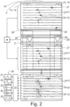
- Fig. 2 shows the application of the identification routine 9 to a multi-channel intracardiac electrogram 2 and resulting windows W of local activation potentials 12.
- the windows W of the local activation potentials 12 have a width of at most 250 ms, preferably at most 200 ms, more preferably at most 175 ms and more preferably at most 150 ms. Here they have a width of approximately 128 ms.
- the width of the windows W of local activation potentials 12 is at least 50 ms.
- a classification routine 15 the control system 3 analyses the local activation potential 12 to determine the cardiac isolation status of the measurement location 1.
- the classification routine 15 may use the algorithm of EP 3 139 828 B1 .
- the intracardiac electrogram 2 has been recorded during an atrial arrhythmia, in particular atrial fibrillation or atrial flutter.
- the proposed method allows determining the cardiac isolation status even in those cases.
- the measurement location 1 may be at least partly located inside an atrium 16, in particular inside the left atrium 16.
- the measurement location 1 may be an isle 17 in the wall 18 of the left atrium 16 or at the entrance of a pulmonary vein 19.
- a main target are the entrances of the pulmonary veins 19 into the left atrium 16.
- Successfully isolating the pulmonary veins 19 may be the target of an ablation therapy. Therefore the measurement location 1 may be at least partly located inside a pulmonary vein 19.
- the proposed method can be used prior to, during and/or after an ablation therapy. It can be used to determine an isolation status of a potential target for ablation in which case the isolation status may comprise information about how the measurement location 1 is involved with the conduction of electrical activations.
- the cardiac isolation status contains information about how well an ablation therapy has isolated the measurement location 1 from a remainder of the heart.
- the proposed method is used during and or after an ablation therapy. The measurement location 1 may then be the target of the ongoing or concluded ablation therapy.
- the control system 3 analyses a morphology of the local activation potentials 12 to determine the cardiac isolation status of the measurement location 1. It has been found that information about the isolation status is contained in the complexity and amplitude of the local activation potentials 12.
- the morphology of the local activation potentials 12 depends on whether these are caused by propagation of a more global activation of the heart or a local pacing event and whether the general electrical situation is chaotic as in atrial fibrillation.
- control system 3 may classify the local activation potential 12 into morphology groups 20 and preferably determines based on the distribution of local activation potentials 12 across the groups the cardiac isolation status. It is particularly advantageous that incorrectly identified local activation potentials 12, which may be caused by noise or far field interference, often show a morphology distinct from the morphology of local activation potentials 12 from a non-isolated location or an isolated location, allowing to ignore these false detections.
- the control system 3 may classify local activation potentials 12 into morphology groups 20 based on a number of characteristic peaks of the local activation potential 12. For this, not every plateau in the electrogram 2 necessarily counts as a characteristic peak.
- the control system 3 classifies a peak with at least a predetermined amplitude and/or with at least a predetermined slope and/or with at most a predetermined slope and/or with at least a predetermined minimum peak distance and/or with at most a predetermined maximum peak distance and/or based on a peak morphology, in particular a minimum and/or maximum peak angle, as a characteristic peak. Classification as a characteristic peak can also be based on the peaks having a predetermined peak frequency and/or a predetermined peak sharpness.
- the morphology groups 20 comprise a group for local activation potentials 12 with a single characteristic peak, "monophasic 21", and/or a group for local activation potentials 12 with exactly two characteristic peaks, “biphasic 22" and/or exactly three characteristic peaks, “triphasic 23", and/or more than three characteristic peaks, "multiphasic 24".
- the morphology groups 20 may further or alternatively comprise a group for local activation potentials 12 with at least two characteristic peaks separated by a predetermined time, "double potentials 25". They may further comprise a group for local activation potentials 12 that show a morphology associated with erroneously detected local activation potentials 12 either stemming from noise or far field interference for example.
- the analysis windows 10 may have a width of at least 400 ms, preferably at least 800 ms, more preferably at least 1,25 s. In a preferred embodiment, the analysis windows 10 may have a width of at most 3 s, preferably at most 2 s, more preferably at most 1,75 s. Here the analysis windows 10 have a width of 1,5 s.
- the analysis windows 10 may be overlapping or non-overlapping sliding windows over a measurement time for each channel.
- at least two local activation potentials 12 are extracted per channel 11 whereby in particular at least one local activation potential 12 may be extracted per analysis window 10.
- the measurement time may be chosen to be at least 1 s, preferably at least 2,5 s, more preferably at least 5 s.
- the measurement time may be chosen to be at most 10 s.
- control system 3 may carry out the identification routine 9 and the classification routine 15 on a multi-channel intracardiac electrogram 2 of the measurement location 1 recorded after an ablation procedure applied near to, in particular around, the measurement location 1 to determine the cardiac isolation status of the measurement location 1.
- the control system 3 may thereby evaluate the success of the ablation procedure.
- control system 3 carries out at least the identification routine 9 on a multi-channel intracardiac electrogram 2 of the measurement location 1 recorded prior to the ablation procedure and determines the cardiac isolation status based on a comparison of the local activation potentials 12 prior to and after the ablation procedure.
- the measurement locations 1 prior to and after the ablation procedure do not have to be identical, a reasonable co-incidence may suffice.
- the activation search algorithm may comprise a peak detection algorithm for finding the local activation potentials 12 and subsequently the windows W of the local activation potentials 12.
- the peak detection algorithm may be based on non-linear filters, in particular wavelet filters, and/or it may be based on a transformation of the electrogram 2, in particular a wavelet transformation.
- the peak detection algorithm may comprise a peak detection by an amplitude. For example, the highest amplitude inside of a given time frame may be detected as a peak.
- the control system 3 may identify a fixed number of local activation potentials 12 per channel 11 and/or per analysis window 10.
- the control system 3 in the identification routine 9 may identify a fixed number of local activation potentials 12 per time interval. This time interval may be the measurement window.
- the fixed number may be based on a physiological and/or measured heartrate. It may be the case that the fixed number is a maximum of one local activation potential 12 per at least 500 ms, preferably per at least 800 ms, more preferably per at least 1 s.
- the control system 3 may execute an interference signal removal step prior to the identification step.
- the interference signal removal step may comprise complete or weighted blanking of time intervals 26 around and/or relative to pacing artefacts and or CS-potentials 13 and or ECG-waves 27.
- ECG-waves 27 may comprise P-waves, QRS-complexes and/or T-waves, that can be associated with atrial and ventricular activity. Generally, other artefacts may be blanked too. This blanking in the weighted form is shown in fig. 2 .
- the blanking can be seen as removing part of the electrogram 2 or multiplying the respective part of the electrogram 2 with zero.
- the blanking is applied to all channels 11.
- the blanked time interval 26 of the electrogram 2 is not completely multiplied with zero. It may be only reduced in amplitude, in particular at the edges and near the edges of the time interval 26, where the far field interference is expected to be moderate. This makes it possible to find local activation potentials 12 partly overlapping with the blanked time interval 26.
- the pacing artefacts and/or the CS-potentials 13 and or the ECG-waves 27 may be detected on an electrogram 2 different from the multi-channel intracardiac electrogram 2, the electrogram 2 be a coronary sinus or a surface electrogram 2. These are generally more suited to identify for example CS-potentials 13 and ECG-waves 27, such as P-waves, QRS-complexes and T-waves, associated with the atrial and ventricular activity, than a potentially isolated pulmonary vein 19 electrogram 2.
- the CS-potentials 13 and ECG-waves 27 may be detected by known algorithms, for example by using peak detection on the surface electrogram 2.
- the pacing artefacts can be detected through peak amplitude detection and/or slope analysis.
- a classification of interference signals may be done and may be used for blanking said interference signals.
- the interference signals are classified as at least one of pacing artifacts and/or far field interference and/or instable activation potentials and/or noisy activation potentials. Detected interference signals may be excluded from being identified as local activation potentials 12.
- Pacing artifacts are signals generated by methods of cardiac pacing.
- the pacing artifacts may be classified by analysing voltage characteristics, in particular a slope of the channels 11.
- Local activation potentials 12 show a physiological delay between channels 11 respectively the real locations associated with the channels. Therefore, the control system 3 may classify signals that occur inside of a predetermined short time window within many or all channels 11 as pacing artifacts.
- the control system 3 may comprise an input for external pacing timing.
- the far field interference may be classified by determining the timing of the QRS activations from a surface ECG, for example through delineation of the ECG in P-waves, QRS-complexes and/or T-waves, wherein each wave may be associated with specific atrial or ventricular activity.
- Instable activation potentials may be such activation potentials that have an energy which is not well localized, have baseline deviations and/or large wave-to-wave amplitude deviations. These instable activation potentials may be excluded from further analysis, in particular by blanking.
- the instable activation potentials can be classified based on expected waveforms of the surface ECG and/or the intracardiac electrogram 2. Alternatively, instable activation potentials can be identified in the classification routine 15.
- noisy activation potentials are such activation potentials where the noise spectrum overlaps the physiological spectrum in a relevant manner.
- the weighted blanking is an application of different weights 28 to the electrogram 2 inside the respective time interval 26.
- the weights 28 are predetermined to comprise a section of complete removal of the respective time interval 26, for example a multiplication with zero, and at least one section of reducing the amplitude of the electrogram 2.
- the weighted blanking can be applied by other methods than multiplication.
- An example of weights 28 may be a gauss curve.
- the weighted blanking can be parameterized, in particular regarding the weights and/or the length of the blanking, based on the classification of the interference signal that is to be blanked. This way it becomes possible to detect local activation potentials 12 that have a high probability of showing a clear signal even during atrial fibrillation thereby allowing the analysis of local activation potentials during atrial fibrillation.
- a pacing artifact can be entirely suppressed from the onset and a defined period following the onset after which the blanking is reduced.
- the length and/or reduction may be specific to hardware or software filter settings used with the control system 3.
- a QRS complex may be dynamically penalized estimated from the associated influence on the last few beats.
- the present approach allows to track a local activation potential 12 that gradually delays and overlaps the QRS timing, which happens often at the critical moment of isolation. Therefore, the present approach allows determining the cardiac isolation status during an isolation procedure and during atrial fibrillation without the necessity to cardiovert the patient to a normal sinus rhythm.
- Fig. 2 shows another example for a blanking of a time interval 29, in this case relative to the CS-potentials 13.
- a complete blanking of the signal in time intervals 29 may be performed by multiplication with zero.
- the interference signal removal step in particular by means of blanking, may be performed with regard to the identification step on the intracardiac electrogram 2, while the classification routine 15 may be based on an analysis of the local activation potentials 12 in the intracardiac electrogram 2 without or a different type of interference signal removal as used for the identification.
- the control system 3 may further execute a quality control step.
- the control system 3 removes local activation potentials 12 and/or time sections of electrogram 2 channels 11 and/or electrogram 2 channels 11 as such, based on a quality parameter.
- the quality parameter may be a noise parameter, preferably a root-mean-square ratio and/or based on a power-line interference detection and/or the noise parameter may be a peak-to-baseline ratio.
- the multi-channel electrogram 2 may comprise at least four, preferably at least six, more preferably at least eight channels 11.
- the multi-channel electrogram 2 may have been recorded by an ablation catheter 6.
- Other possibilities are a circular catheter 6 or a multi-spline catheter 6 for example.
- the multi-channel electrogram 2 may be a bipolar electrogram. In a preferred alternative, the multi-channel electrogram 2 is a unipolar electrogram.
- control system 3 configured to perform the proposed method. All explanations given with regards to the proposed method are fully applicable.
- the control system 3 is configured to receive and/or measure the multi-channel electrogram 2.
- the control system 3 is preferably connectable to the ablation catheter 6.
Landscapes
- Health & Medical Sciences (AREA)
- Life Sciences & Earth Sciences (AREA)
- Engineering & Computer Science (AREA)
- Physics & Mathematics (AREA)
- Public Health (AREA)
- Medical Informatics (AREA)
- Biomedical Technology (AREA)
- Pathology (AREA)
- General Health & Medical Sciences (AREA)
- Cardiology (AREA)
- Molecular Biology (AREA)
- Animal Behavior & Ethology (AREA)
- Biophysics (AREA)
- Veterinary Medicine (AREA)
- Surgery (AREA)
- Heart & Thoracic Surgery (AREA)
- Signal Processing (AREA)
- Artificial Intelligence (AREA)
- Physiology (AREA)
- Psychiatry (AREA)
- Computer Vision & Pattern Recognition (AREA)
- Evolutionary Computation (AREA)
- Mathematical Physics (AREA)
- Fuzzy Systems (AREA)
- Data Mining & Analysis (AREA)
- Databases & Information Systems (AREA)
- Epidemiology (AREA)
- Primary Health Care (AREA)
- Measurement And Recording Of Electrical Phenomena And Electrical Characteristics Of The Living Body (AREA)
Description
- The invention relates to a method for determining a cardiac isolation status of a measurement location in the presence of far field interference according to
claim 1 and to a control system adapted to execute the method according toclaim 15. - The present method is particularly concerned with atrial fibrillation and atrial flutter. Electrically, atrial fibrillation is chaotic activation of muscle cells of the atrial. During atrial fibrillation, the atria only minimally contribute to the function of the heart. Atrial fibrillation, therefore, reduces the output of the heart but is not imminently dangerous. However, when becoming chronical, atrial fibrillation is correlated width increased morbidity and mortality. One treatment option for atrial fibrillation is ablation therapy. Ablation is the destruction of the cells that allow electrical wave re-entry to reduce chaotic activation of the atrial muscle cells.
- A recommended treatment for atrial fibrillation includes pulmonary vein isolation. Pulmonary vein isolation can be performed with various ablation techniques, including radio frequency ablation, cryo balloon ablation and pulsed-field ablation. While these techniques apply energy differently, their common endpoint is the isolation of the electrical activity of the pulmonary veins from the rest of the atrium.
- Generally, ablation therapy is successful, if the targeted location is electrically isolated from the rest of the heart. There are different methods for assessing the success of the ablation therapy. These include costly 3D mapping of ablation points and measurements of force or temperature during ablation and electrogram analysis.
- One known method (
EP 3 139 828 B1 ) focusses on a morphology analysis of local activation potentials of a measurement location. In this method, the local activation potentials are classified into groups according to the number and characteristics of their peaks. An analysis of the distribution of the potentials across the morphological groups allows a good classification of a cardiac isolation status of the measurement location. A method based on electrical signals is cheap in the implementation and easily usable. Further, measuring electrical waves targets the actual physical effect underlying atrial fibrillation rather than a secondary factor. - The known method provides good results. However, in the known method the local activation potentials of the measurement location are detected based on the detection of a reference CS-potential. This CS-potential is detected by a coronary sinus catheter. Based on this reference CS-potential, a predetermined window of approximately 200ms is chosen. This window is defined a s containing the local activation potentials of the channels related to the measurement location. Therefore, the reliability of the known method depends on the patient being in a sinus rhythm.
- Further methods are known from
US 2002/019593 A1 , which discloses a method of classifying cardiac complexes to determine different states of tachycardia, andEP 3 451 917 A1 , which discloses a cardiac mapping system. - There exists a demand for a method for determining an isolation status using electrograms and analysis of local activation potentials usable without a-priori knowledge about the location of the local activation potentials from a reference potential. This is necessary for example if a cardiac isolation status of a patient should be determined while the patient is in atrial fibrillation. During atrial fibrillation, the time relation between the CS-potential and local activations may be broken. While the possibility to cardiovert a patient to a normal sinus rhythm exists, this may not always be desired.
- It is further problematic that cardiac electrograms contain not only local activation potentials but also far field interference. Measurement of the CS-potential also typically requires a separate CS-catheter in addition to a catheter that may be located in the pulmonary vein. It is desirable to identify methods for determining cardiac isolation status that can also be performed with a single catheter.
- It is therefore an object of the present invention to provide a method for detecting a cardiac isolation status in the presence of far field interference usable without being able to rely on a reference CS-potential for detecting local activations.
- The above-noted object is solved by the method of
claim 1. - The main realization of the present invention is that by analyzing multiple channels of an intracardiac electrogram independently and searching for local activation potentials on the channels without using a single resulting time window on all channels, sufficient actual local activation potentials can be found even during atrial fibrillation to enable analyzing those local activation potentials to determine a cardiac isolation status of the measurement location.
- In particular, this enables determining a cardiac isolation status of a measurement location during atrial fibrillation.
- In detail, a method for determining a cardiac isolation status of a measurement location in the presence of far field interference by analyzing a multi-channel intracardiac electrogram of the measurement location via a control system, wherein in an identification routine the control system applies an activation search algorithm to analysis windows of at least 400 ms in at least two different channels of the intracardiac electrogram, wherein the activation search algorithm identifies windows of local activation potentials inside of the analysis windows, wherein in a classification routine the control system analyzes the local activation potentials to determine the cardiac isolation status of the measurement location, is proposed.
-
Claim 2 specifies the very preferred applications of the proposed method. In particular during atrial fibrillation or atrial flutter, local activation potentials, particularly pulmonary vein local activation potentials, cannot be detected by relying on a-priori-knowledge about their position in time from a reference CS-potential. - In an embodiment according to claim 3, the control system analyses in the classification routine a morphology of the local activation potentials to determine a cardiac isolation status. It has been realized that a morphology classification of local activation potentials can be done effectively even during atrial fibrillation. Claim 4 specifies preferred details of the classification routine. In general, morphologies with less fractionated peaks, lower peak frequencies, lower peak sharpness and peaks of lesser amplitudes indicate a successful isolation.
Claim 5 relates to different preferred morphology groups that have been shown to enable a successful isolation status determination. - The embodiments of claim 6 relate to preferred widths of the analysis windows chosen to ensure mostly having at least one physiological local activation potential in each analysis window. It is preferred to choose the width of the analysis window such that at least one physiological local activation potential is present in each analysis window. This allows adapting the activation search algorithm such that it can always find a local activation potential because the analysis window contains at least one. For the present algorithm it is not necessary to find all local activation potentials. Nevertheless, in an embodiment according to
claim 7, sliding windows are used to find multiple local activation potentials per channel. - Claim 8 is concerned with the possibility of using the proposed method to verify the success of an ablation procedure. As an ablation procedure is an invasive surgical operation, observing a patient for days to determine the success of an ablation procedure is not preferred. Rather, the success of the ablation procedure should be determined during the intervention.
- The activation search algorithm may comprise a peak detection algorithm described in
claim 9. - The control system may identify a fixed number of local activation potentials per channel (claim 10). This number may be smaller or equal to the number of physiologically present local activation potentials. In this way the number of incorrectly identified local activation potentials can be reduced.
- In a preferred embodiment according to
claim 11, the control system may execute an interference signal removal step prior to the identification step, in particular to remove far field interference signals.Claim 11 names removal of signals around and/or relative to pacing artifacts, CS-potentials and ECG-waves. By removing time windows related to sources of far field interference, the chance of detecting actual local activation potentials is greatly increased. This removal is called blanking. Such blanking may also be done in a weighted manner to enable identifying local activation potentials that partly overlap with the blanked time frames. The blanking may for example be weighted by a gauss curve fully or almost fully removing the electrogram in the middle of the time window to be blanked and only reducing an amplitude at the edges. Further details of the weighted blanking are subject ofclaim 12. - To reduce a number of incorrectly identified local activation potentials, the control system may execute a quality control step according to claim 13. Sections of the electrogram or even channels of the electrogram may be removed from consideration before or after the identification step based on a quality parameter.
- Claim 14 relates to preferably used catheters.
- Another teaching according to
claim 15, which is of equal importance, is directed to a control system configured to perform the proposed method. All explanations given with respect to the proposed method are fully applicable. - In the following, an embodiment of the invention is explained with respect to the drawings. The drawings show in
- fig. 1
- the proposed control system during the measurement of a multi-channel intracardiac electrogram, and in
- fig. 2
- the proposed method in an exemplary application.
- The proposed method is used for determining a cardiac isolation status of a
measurement location 1 in the presence of far field interference by analysing amulti-channel intracardiac electrogram 2 of themeasurement location 1 via a control system 3. The cardiac isolation status may be a binary yes/no decision or a percentage of a probability of isolation of themeasurement location 1. Themulti-channel intracardiac electrogram 2 is preferably measured by an intracardiac catheter 4 comprising a number ofelectrodes 5, for example tenelectrodes 5. Theseelectrodes 5 have a certain spatial extension. Therefore, themeasurement location 1 also has a certain spatial extension. It is not necessary however for allelectrodes 5 of the measurement catheter 6 to be located at themeasurement location 1. It might be the case that the measurement catheter 6 is placed across a boundary of anablation lesion 7 for example. - The control system 3 may be a local unit 8 with a processor, possibly a user interface and the like as shown in
fig. 1 . It may also comprise in one embodiment a cloud processor. It this therefore not necessary for the control system 3 to be confined to a single device. - In an
identification routine 9 the control system 3 applies an activation search algorithm toanalysis windows 10 of at least 400ms in at least twodifferent channels 11 of theintracardiac electrogram 2. Achannel 11 is defined as the measurement between at least twoelectrodes 5. The proposed method serves to determine a cardiac isolation status whenlocal activation potentials 12 cannot be reliably located relative to a reference CS-potential 13. This is particularly true during atrial fibrillation. - The activation search algorithm identifies windows W of
local activation potentials 12 inside of theanalysis windows 10. It is essential that these windows W oflocal activation potentials 12 can differ regarding their location in time betweenchannels 11 and are not set equal for allchannels 11 relative to the timing of a reference potential 14. Therefore, the search field for these windows W is chosen to be at least 400 ms wide. In general, the windows W of thelocal activation potentials 12 should comprise all or most of the relevant waveform of the respectivelocal activation potential 12. The activation search algorithm may be an algorithm searching directly for the window W or searching for a single point in time assigned to thelocal activation potential 12 and derive the window W from there. - By searching
local activation potentials 12 without a reference timing, it becomes possible to determine a cardiac isolation status without knowledge about any reference timing. -
Fig. 2 shows the application of theidentification routine 9 to amulti-channel intracardiac electrogram 2 and resulting windows W oflocal activation potentials 12. Here and preferably the windows W of thelocal activation potentials 12 have a width of at most 250 ms, preferably at most 200 ms, more preferably at most 175 ms and more preferably at most 150 ms. Here they have a width of approximately 128 ms. Preferably, the width of the windows W oflocal activation potentials 12 is at least 50 ms. - In a
classification routine 15 the control system 3 analyses the local activation potential 12 to determine the cardiac isolation status of themeasurement location 1. Theclassification routine 15 may use the algorithm ofEP 3 139 828 B1 . - As has already been described, it is preferred that the
intracardiac electrogram 2 has been recorded during an atrial arrhythmia, in particular atrial fibrillation or atrial flutter. The proposed method allows determining the cardiac isolation status even in those cases. - As is schematically shown in
fig. 1 , themeasurement location 1 may be at least partly located inside anatrium 16, in particular inside theleft atrium 16. Themeasurement location 1 may be anisle 17 in thewall 18 of theleft atrium 16 or at the entrance of apulmonary vein 19. There are different locations that can be targeted with ablation. A main target are the entrances of thepulmonary veins 19 into theleft atrium 16. Successfully isolating thepulmonary veins 19 may be the target of an ablation therapy. Therefore themeasurement location 1 may be at least partly located inside apulmonary vein 19. - In general, the proposed method can be used prior to, during and/or after an ablation therapy. It can be used to determine an isolation status of a potential target for ablation in which case the isolation status may comprise information about how the
measurement location 1 is involved with the conduction of electrical activations. Here and preferably the cardiac isolation status contains information about how well an ablation therapy has isolated themeasurement location 1 from a remainder of the heart. Here and preferably the proposed method is used during and or after an ablation therapy. Themeasurement location 1 may then be the target of the ongoing or concluded ablation therapy. - Turning now to the
classification routine 15, it may be the case that in theclassification routine 15 the control system 3 analyses a morphology of thelocal activation potentials 12 to determine the cardiac isolation status of themeasurement location 1. It has been found that information about the isolation status is contained in the complexity and amplitude of thelocal activation potentials 12. The morphology of thelocal activation potentials 12 depends on whether these are caused by propagation of a more global activation of the heart or a local pacing event and whether the general electrical situation is chaotic as in atrial fibrillation. - In the
classification routine 15 the control system 3 may classify the local activation potential 12 intomorphology groups 20 and preferably determines based on the distribution oflocal activation potentials 12 across the groups the cardiac isolation status. It is particularly advantageous that incorrectly identifiedlocal activation potentials 12, which may be caused by noise or far field interference, often show a morphology distinct from the morphology oflocal activation potentials 12 from a non-isolated location or an isolated location, allowing to ignore these false detections. - The control system 3 may classify
local activation potentials 12 intomorphology groups 20 based on a number of characteristic peaks of thelocal activation potential 12. For this, not every plateau in theelectrogram 2 necessarily counts as a characteristic peak. Preferably, the control system 3 classifies a peak with at least a predetermined amplitude and/or with at least a predetermined slope and/or with at most a predetermined slope and/or with at least a predetermined minimum peak distance and/or with at most a predetermined maximum peak distance and/or based on a peak morphology, in particular a minimum and/or maximum peak angle, as a characteristic peak. Classification as a characteristic peak can also be based on the peaks having a predetermined peak frequency and/or a predetermined peak sharpness. - Here and preferably the
morphology groups 20 comprise a group forlocal activation potentials 12 with a single characteristic peak, "monophasic 21", and/or a group forlocal activation potentials 12 with exactly two characteristic peaks, "biphasic 22" and/or exactly three characteristic peaks, "triphasic 23", and/or more than three characteristic peaks, "multiphasic 24". The morphology groups 20 may further or alternatively comprise a group forlocal activation potentials 12 with at least two characteristic peaks separated by a predetermined time, "double potentials 25". They may further comprise a group forlocal activation potentials 12 that show a morphology associated with erroneously detectedlocal activation potentials 12 either stemming from noise or far field interference for example. - It is preferred to chose the
analysis windows 10 such that at least one physiologicallocal activation potential 12 is probably or surely present. For this, theanalysis windows 10 may have a width of at least 400 ms, preferably at least 800 ms, more preferably at least 1,25 s. In a preferred embodiment, theanalysis windows 10 may have a width of at most 3 s, preferably at most 2 s, more preferably at most 1,75 s. Here theanalysis windows 10 have a width of 1,5 s. - It is preferred to extract multiple
local activation potentials 12 from eachchannel 11 to enable a good statistical analysis of thelocal activation potentials 12, in particular of theirmorphology groups 20. Here and preferably in total at least 2, preferably at least 5, in particular at most 10,local activation potentials 12 are extracted. To extract multiplelocal activation potentials 12 per channel, theanalysis windows 10 may be overlapping or non-overlapping sliding windows over a measurement time for each channel. Preferably at least twolocal activation potentials 12 are extracted perchannel 11 whereby in particular at least onelocal activation potential 12 may be extracted peranalysis window 10. The measurement time may be chosen to be at least 1 s, preferably at least 2,5 s, more preferably at least 5 s. The measurement time may be chosen to be at most 10 s. - As mentioned above, the control system 3 may carry out the
identification routine 9 and theclassification routine 15 on amulti-channel intracardiac electrogram 2 of themeasurement location 1 recorded after an ablation procedure applied near to, in particular around, themeasurement location 1 to determine the cardiac isolation status of themeasurement location 1. The control system 3 may thereby evaluate the success of the ablation procedure. - It may be preferred to compare data before and after the ablation procedure. Therefore, it may be the case that additionally the control system 3 carries out at least the
identification routine 9 on amulti-channel intracardiac electrogram 2 of themeasurement location 1 recorded prior to the ablation procedure and determines the cardiac isolation status based on a comparison of thelocal activation potentials 12 prior to and after the ablation procedure. Themeasurement locations 1 prior to and after the ablation procedure do not have to be identical, a reasonable co-incidence may suffice. - The activation search algorithm may comprise a peak detection algorithm for finding the
local activation potentials 12 and subsequently the windows W of thelocal activation potentials 12. The peak detection algorithm may be based on non-linear filters, in particular wavelet filters, and/or it may be based on a transformation of theelectrogram 2, in particular a wavelet transformation. The peak detection algorithm may comprise a peak detection by an amplitude. For example, the highest amplitude inside of a given time frame may be detected as a peak. - Returning to the detection of
local activation potentials 12 by taking into consideration their frequency under physiological conditions, in theidentification routine 9 the control system 3 may identify a fixed number oflocal activation potentials 12 perchannel 11 and/or peranalysis window 10. Preferably the control system 3 in theidentification routine 9 may identify a fixed number oflocal activation potentials 12 per time interval. This time interval may be the measurement window. The fixed number may be based on a physiological and/or measured heartrate. It may be the case that the fixed number is a maximum of one local activation potential 12 per at least 500 ms, preferably per at least 800 ms, more preferably per at least 1 s. By detecting only a singlelocal activation potential 12 inside of any given time window, for example 800 ms, it is possible to ensure that the activation search algorithm always has the possibility of finding a reallocal activation potential 12. - With regards to
fig. 2 the removal of interference signals, in particular from far field interference, will now be described in more detail. The control system 3 may execute an interference signal removal step prior to the identification step. The interference signal removal step may comprise complete or weighted blanking oftime intervals 26 around and/or relative to pacing artefacts and or CS-potentials 13 and or ECG-waves 27. ECG-waves 27 may comprise P-waves, QRS-complexes and/or T-waves, that can be associated with atrial and ventricular activity. Generally, other artefacts may be blanked too. This blanking in the weighted form is shown infig. 2 . - In a simple embodiment, the blanking can be seen as removing part of the
electrogram 2 or multiplying the respective part of theelectrogram 2 with zero. Here and preferably the blanking is applied to allchannels 11. In the weighted form, the blankedtime interval 26 of theelectrogram 2 is not completely multiplied with zero. It may be only reduced in amplitude, in particular at the edges and near the edges of thetime interval 26, where the far field interference is expected to be moderate. This makes it possible to findlocal activation potentials 12 partly overlapping with the blankedtime interval 26. - The pacing artefacts and/or the CS-potentials 13 and or the ECG-
waves 27 may be detected on anelectrogram 2 different from themulti-channel intracardiac electrogram 2, theelectrogram 2 be a coronary sinus or asurface electrogram 2. These are generally more suited to identify for example CS-potentials 13 and ECG-waves 27, such as P-waves, QRS-complexes and T-waves, associated with the atrial and ventricular activity, than a potentially isolatedpulmonary vein 19electrogram 2. - The CS-potentials 13 and ECG-
waves 27 may be detected by known algorithms, for example by using peak detection on thesurface electrogram 2. The pacing artefacts can be detected through peak amplitude detection and/or slope analysis. - As part of the interference signal removal step or as an independent step, a classification of interference signals may be done and may be used for blanking said interference signals. Here and preferably, the interference signals are classified as at least one of pacing artifacts and/or far field interference and/or instable activation potentials and/or noisy activation potentials. Detected interference signals may be excluded from being identified as
local activation potentials 12. - Pacing artifacts are signals generated by methods of cardiac pacing. The pacing artifacts may be classified by analysing voltage characteristics, in particular a slope of the
channels 11.Local activation potentials 12 show a physiological delay betweenchannels 11 respectively the real locations associated with the channels. Therefore, the control system 3 may classify signals that occur inside of a predetermined short time window within many or allchannels 11 as pacing artifacts. Alternatively, the control system 3 may comprise an input for external pacing timing. - The far field interference may be classified by determining the timing of the QRS activations from a surface ECG, for example through delineation of the ECG in P-waves, QRS-complexes and/or T-waves, wherein each wave may be associated with specific atrial or ventricular activity.
- Instable activation potentials may be such activation potentials that have an energy which is not well localized, have baseline deviations and/or large wave-to-wave amplitude deviations. These instable activation potentials may be excluded from further analysis, in particular by blanking. The instable activation potentials can be classified based on expected waveforms of the surface ECG and/or the
intracardiac electrogram 2. Alternatively, instable activation potentials can be identified in theclassification routine 15. - Noisy activation potentials are such activation potentials where the noise spectrum overlaps the physiological spectrum in a relevant manner. Known methods for noise estimation can be used. Here and preferably the weighted blanking is an application of
different weights 28 to theelectrogram 2 inside therespective time interval 26. Preferably theweights 28 are predetermined to comprise a section of complete removal of therespective time interval 26, for example a multiplication with zero, and at least one section of reducing the amplitude of theelectrogram 2. The weighted blanking can be applied by other methods than multiplication. An example ofweights 28 may be a gauss curve. - The weighted blanking can be parameterized, in particular regarding the weights and/or the length of the blanking, based on the classification of the interference signal that is to be blanked. This way it becomes possible to detect
local activation potentials 12 that have a high probability of showing a clear signal even during atrial fibrillation thereby allowing the analysis of local activation potentials during atrial fibrillation. - As an example, a pacing artifact can be entirely suppressed from the onset and a defined period following the onset after which the blanking is reduced. The length and/or reduction may be specific to hardware or software filter settings used with the control system 3.
- A QRS complex may be dynamically penalized estimated from the associated influence on the last few beats. The present approach allows to track a local activation potential 12 that gradually delays and overlaps the QRS timing, which happens often at the critical moment of isolation. Therefore, the present approach allows determining the cardiac isolation status during an isolation procedure and during atrial fibrillation without the necessity to cardiovert the patient to a normal sinus rhythm.
-
Fig. 2 shows another example for a blanking of atime interval 29, in this case relative to the CS-potentials 13. Here, a complete blanking of the signal intime intervals 29 may be performed by multiplication with zero. - The interference signal removal step, in particular by means of blanking, may be performed with regard to the identification step on the
intracardiac electrogram 2, while theclassification routine 15 may be based on an analysis of thelocal activation potentials 12 in theintracardiac electrogram 2 without or a different type of interference signal removal as used for the identification. - The control system 3 may further execute a quality control step. In the quality control step, the control system 3 removes
local activation potentials 12 and/or time sections ofelectrogram 2channels 11 and/orelectrogram 2channels 11 as such, based on a quality parameter. The quality parameter may be a noise parameter, preferably a root-mean-square ratio and/or based on a power-line interference detection and/or the noise parameter may be a peak-to-baseline ratio. - With regards to
fig. 1 , themulti-channel electrogram 2 may comprise at least four, preferably at least six, more preferably at least eightchannels 11. Themulti-channel electrogram 2 may have been recorded by an ablation catheter 6. Other possibilities are a circular catheter 6 or a multi-spline catheter 6 for example. Themulti-channel electrogram 2 may be a bipolar electrogram. In a preferred alternative, themulti-channel electrogram 2 is a unipolar electrogram. - According to another teaching, which is of equal importance, a control system 3 configured to perform the proposed method is proposed. All explanations given with regards to the proposed method are fully applicable. The control system 3 is configured to receive and/or measure the
multi-channel electrogram 2. The control system 3 is preferably connectable to the ablation catheter 6.
Claims (15)
- Method for determining a cardiac isolation status of a measurement location (1) in the presence of far field interference by analysing a multi-channel intracardiac electrogram (2) of the measurement location (1) via a control system (3),wherein in an identification routine (9) the control system (3) applies an activation search algorithm to analysis windows (10) of at least 400 ms in at least two different channels (11) of the intracardiac electrogram (2), wherein the activation search algorithm identifies windows (W) of local activation potentials (12) inside of the analysis windows (10),wherein in a classification routine (15) the control system (3) analyses the local activation potentials (12) to determine the cardiac isolation status of the measurement location (1).
- Method according to claim 1, characterized in that the intracardiac electrogram (2) has been recorded during an atrial arrhythmia, in particular atrial fibrillation or atrial flutter, and/or, that the measurement location (1) is at least partly located inside an atrium (16), in particular the left atrium (16), preferably that the measurement location (1) is an isle (17) in the wall (18) of the left atrium (16) or at the entrance of a pulmonary vein (19), and/or, that the measurement location (1) is at least partly located inside a pulmonary vein (19).
- Method according to claim 1 or 2, characterized in that in the classification routine (15) the control system (3) analyses a morphology of the local activation potentials (12) to determine the cardiac isolation status of the measurement location (1), preferably that in the classification routine (15) the control system (3) classifies the local activation potentials (12) into morphology groups (20) and preferably determines based on the distribution of local activation potentials (12) across the groups the cardiac isolation status.
- Method according to claim 3, characterized in that in the classification routine (15) the control system (3) classifies the local activation potentials (12) into morphology groups (20) based on a number of characteristic peaks of the local activation potential (12), preferably that the control system (3) classifies a peak with at least a predetermined amplitude and/or with at least a predetermined slope and/or with at most a predetermined slope and/or with at least a predetermined minimum peak distance and/or with at most a predetermined maximum peak distance and/or based on a peak morphology, in particular a minimum and/or maximum peak angle, as a characteristic peak.
- Method according to claim 4, characterized in that the morphology groups (20) comprise a group for local activation potentials (12) with a single characteristic peak and/or exactly two characteristic peaks and/or exactly three characteristic peaks and/or more than three characteristic peaks and/or at least two characteristic peaks separated by a predetermined time.
- Method according to one of the preceding claims, characterized in that the analysis windows (10) have a width of at least 400 ms, preferably at least 800 ms, more preferably at least 1,25 s, and/or that the analysis windows (10) have a width of at most 3 s, preferably at most 2 s, more preferably at most 1,75 s.
- Method according to one of the preceding claims, characterized in that the analysis windows (10) are overlapping or non-overlapping sliding windows over a measurement time for each channel, preferably that at least two local activation potentials (12) are extracted per channel, in particular at least one local activation potential (12) is extracted per analysis window (10), more preferably that the measurement time is at least 1 s, preferably at least 2,5 s, more preferably at least 10 s.
- Method according to one of the preceding claims, characterized in that the control system (3) carries out the identification routine (9) and the classification routine (15) on a multi-channel intracardiac electrogram (2) of the measurement location (1) recorded after an ablation procedure applied near to, in particular around, the measurement location (1) to determine the cardiac isolation status of the measurement location (1), preferably that additionally the control system (3) carries out at least the identification routine (9) on a multi-channel intracardiac electrogram (2) of the measurement location (1) recorded prior to the ablation procedure and determines the cardiac isolation status based on a comparison of the local activation potentials (12) prior to and after the ablation procedure.
- Method according to one of the preceding claims, characterized in that the activation search algorithm comprises a peak detection algorithm for finding the local activation potentials (12) and subsequently the windows (W) of the local activation potentials (12), preferably that the peak detection algorithm is based on non-linear filters, in particular wavelet filters, and/or a transformation of the electrogram (2), in particular a wavelet transformation, and/or comprises a peak detection by amplitude.
- Method according to one of the preceding claims, characterized in that in the identification routine (9) the control system (3) identifies a fixed number of local activation potentials (12) per channel and/or per analysis window (10), preferably a fixed number per time interval (26), in particular per measurement window, more preferably that the fixed number is based on a physiological and/or measured heart rate, more preferably that the fixed number is a maximum of one local activation potential (12) per at least 500 ms, preferably per at least 800 ms, more preferably per at least 1 s.
- Method according to one of the preceding claims, characterized in that the control system (3) executes an interference signal removal step prior to the identification step, the interference signal removal step comprising complete or weighted blanking of time intervals (26) around and/or relative to pacing artefacts and/or CS-potentials (13) and/or ECG-waves (27), preferably that the pacing artefacts and/or CS-potentials (13) and/or ECG-waves (27) are detected on an electrogram (2) different from the multi-channel intracardiac electrogram (2), the electrogram (2) being a coronary sinus or surface electrogram (2).
- Method according to one of the preceding claims, characterized in that the weighted blanking is an application of different weights (28) to the electrogram (2) inside the respective time interval (26), preferably that the weights (28) are predetermined to comprise a section of complete removal of the respective time interval (26) and at least one section of reducing the amplitude of the electrogram (2).
- Method according to one of the preceding claims, characterized in that the control system (3) executes a quality control step, that in the quality control step the control system (3) removes local activation potentials (12) and/or time sections of electrogram (2) channels (11) and or electrogram (2) channels (11) based on a quality parameter, preferably that the quality parameter is a noise parameter, more preferably a root-mean-square ratio and/or based on a power-line interference detection and/or a peak-to-baseline ratio.
- Method according to one of the preceding claims, characterized in that the multi-channel electrogram (2) comprises at least four, preferably at least six, more preferably at least eight channels (11), and/or, that the multi-channel electrogram (2) was recorded by an ablation catheter (6).
- Control system configured to perform the method according to one of the preceding claims, wherein the control system (3) is configured to receive and/or measure the multi-channel electrogram (2), preferably wherein the control system (3) is connectable to the ablation catheter (6).
Priority Applications (6)
| Application Number | Priority Date | Filing Date | Title |
|---|---|---|---|
| EP21192435.2A EP4137052B1 (en) | 2021-08-20 | 2021-08-20 | Method for detecting a cardiac isolation status of a measurement location in the presence of far field interference |
| ES21192435T ES2989166T3 (en) | 2021-08-20 | 2021-08-20 | Method for detecting a cardiac isolation state from a measurement location in the presence of far-field interference |
| US18/684,800 US20240350065A1 (en) | 2021-08-20 | 2022-08-03 | Method for detecting a cardiac isolation status of a measurement location in the presence of far field interference |
| PCT/EP2022/071843 WO2023020843A1 (en) | 2021-08-20 | 2022-08-03 | Method for detecting a cardiac isolation status of a measurement location in the presence of far field interference |
| CN202280056442.0A CN117835910A (en) | 2021-08-20 | 2022-08-03 | Method for detecting cardiac isolation status at a measurement location in the presence of far-field interference |
| JP2024510482A JP2024534814A (en) | 2021-08-20 | 2022-08-03 | Method for detecting cardiac isolation status of a measurement location in the presence of far-field interference - Patents.com |
Applications Claiming Priority (1)
| Application Number | Priority Date | Filing Date | Title |
|---|---|---|---|
| EP21192435.2A EP4137052B1 (en) | 2021-08-20 | 2021-08-20 | Method for detecting a cardiac isolation status of a measurement location in the presence of far field interference |
Publications (3)
| Publication Number | Publication Date |
|---|---|
| EP4137052A1 EP4137052A1 (en) | 2023-02-22 |
| EP4137052C0 EP4137052C0 (en) | 2024-03-13 |
| EP4137052B1 true EP4137052B1 (en) | 2024-03-13 |
Family
ID=77431244
Family Applications (1)
| Application Number | Title | Priority Date | Filing Date |
|---|---|---|---|
| EP21192435.2A Active EP4137052B1 (en) | 2021-08-20 | 2021-08-20 | Method for detecting a cardiac isolation status of a measurement location in the presence of far field interference |
Country Status (6)
| Country | Link |
|---|---|
| US (1) | US20240350065A1 (en) |
| EP (1) | EP4137052B1 (en) |
| JP (1) | JP2024534814A (en) |
| CN (1) | CN117835910A (en) |
| ES (1) | ES2989166T3 (en) |
| WO (1) | WO2023020843A1 (en) |
Families Citing this family (3)
| Publication number | Priority date | Publication date | Assignee | Title |
|---|---|---|---|---|
| WO2025094132A1 (en) * | 2023-11-01 | 2025-05-08 | Auckland Uniservices Limited | Atrial fibrillation analysis methods, systems and apparatuses |
| EP4628018A1 (en) * | 2024-04-04 | 2025-10-08 | CathVision ApS | Method of analyzing residual local activity after pulsed field ablation of a human heart |
| EP4628019A1 (en) * | 2024-04-04 | 2025-10-08 | CathVision ApS | Method of analyzing an intracardiac electrogram |
Citations (1)
| Publication number | Priority date | Publication date | Assignee | Title |
|---|---|---|---|---|
| EP3451917B1 (en) * | 2016-05-03 | 2021-09-01 | Acutus Medical Inc. | Cardiac mapping system with efficiency algorithm |
Family Cites Families (7)
| Publication number | Priority date | Publication date | Assignee | Title |
|---|---|---|---|---|
| US5184615A (en) * | 1991-03-08 | 1993-02-09 | Telectronics Pacing Systems, Inc. | Apparatus and method for detecting abnormal cardiac rhythms using evoked potential measurements in an arrhythmia control system |
| US6266554B1 (en) * | 1999-02-12 | 2001-07-24 | Cardiac Pacemakers, Inc. | System and method for classifying cardiac complexes |
| US9380953B2 (en) * | 2014-01-29 | 2016-07-05 | Biosense Webster (Israel) Ltd. | Hybrid bipolar/unipolar detection of activation wavefront |
| WO2015169724A1 (en) * | 2014-05-09 | 2015-11-12 | Universiteit Gent | Detection of pulmonary vein isolation |
| TWI522958B (en) * | 2014-06-11 | 2016-02-21 | 國立成功大學 | Physiological signal analysis method and system thereof and computer program product for storing physiological signal analysis program |
| US11534104B2 (en) * | 2014-10-29 | 2022-12-27 | Bloom Technologies NV | Systems and methods for contraction monitoring and labor detection |
| WO2016183683A1 (en) * | 2015-05-20 | 2016-11-24 | University Health Network | Method and system for assessing qrs components and the risk of ventricular arrhythmias |
-
2021
- 2021-08-20 EP EP21192435.2A patent/EP4137052B1/en active Active
- 2021-08-20 ES ES21192435T patent/ES2989166T3/en active Active
-
2022
- 2022-08-03 WO PCT/EP2022/071843 patent/WO2023020843A1/en not_active Ceased
- 2022-08-03 JP JP2024510482A patent/JP2024534814A/en active Pending
- 2022-08-03 CN CN202280056442.0A patent/CN117835910A/en active Pending
- 2022-08-03 US US18/684,800 patent/US20240350065A1/en active Pending
Patent Citations (1)
| Publication number | Priority date | Publication date | Assignee | Title |
|---|---|---|---|---|
| EP3451917B1 (en) * | 2016-05-03 | 2021-09-01 | Acutus Medical Inc. | Cardiac mapping system with efficiency algorithm |
Also Published As
| Publication number | Publication date |
|---|---|
| EP4137052C0 (en) | 2024-03-13 |
| EP4137052A1 (en) | 2023-02-22 |
| WO2023020843A1 (en) | 2023-02-23 |
| CN117835910A (en) | 2024-04-05 |
| ES2989166T3 (en) | 2024-11-25 |
| US20240350065A1 (en) | 2024-10-24 |
| JP2024534814A (en) | 2024-09-26 |
Similar Documents
| Publication | Publication Date | Title |
|---|---|---|
| US20240350065A1 (en) | Method for detecting a cardiac isolation status of a measurement location in the presence of far field interference | |
| US5954661A (en) | Tissue characterization and treatment using pacing | |
| JP4008662B2 (en) | System for classification of tachycardia events | |
| US6308095B1 (en) | System and method for arrhythmia discrimination | |
| US6266554B1 (en) | System and method for classifying cardiac complexes | |
| US20240023870A1 (en) | Cardiac Monitoring System with Normally Conducted QRS Complex Identification | |
| US8521276B2 (en) | Use of significant point methodology to prevent inappropriate therapy | |
| US20030216654A1 (en) | Bayesian discriminator for rapidly detecting arrhythmias | |
| US10335052B2 (en) | Detection of pulmonary vein isolation | |
| Alcaraz et al. | Dynamic time warping applied to estimate atrial fibrillation temporal organization from the surface electrocardiogram | |
| US20250099012A1 (en) | Cardiac monitoring system with supraventricular tachycardia (svt) classifications | |
| JP2024534814A5 (en) | ||
| Krasteva et al. | Assessment of ECG frequency and morphology parameters for automatic classification of life-threatening cardiac arrhythmias | |
| EP4444178B1 (en) | Detection of fractionated signals in stable arrhythmias | |
| Caswell et al. | Pattern recognition of cardiac arrhythmias using two intracardiac channels | |
| JP7775476B2 (en) | Method for analyzing intracardiac electrograms | |
| Caldwell et al. | Relative timing of near-field and far-field electrograms can determine the tachyarrhythmia site of origin | |
| Dube et al. | Automatic detection and classification of human epicardial atrial unipolar electrograms | |
| EP4628018A1 (en) | Method of analyzing residual local activity after pulsed field ablation of a human heart | |
| EP4628019A1 (en) | Method of analyzing an intracardiac electrogram | |
| CN121487690A (en) | Detecting the end time of the T wave in the heart signal using the maximum point of the gradient signal. | |
| Tang et al. | Discrimination of fibrillatory rhythms from intracardiac electrograms using real-time magnitude-squared coherence | |
| Gupta et al. | A novel method for automated fractionation detection in ventricular tachycardia | |
| Shiu et al. | Comparison of polynomial coefficients for pattern recognition of sinus rhythm (SR) and ventricular tachycardia (VT) | |
| Kirchner et al. | Local electrical characterisation of human atrial fibrillation |
Legal Events
| Date | Code | Title | Description |
|---|---|---|---|
| PUAI | Public reference made under article 153(3) epc to a published international application that has entered the european phase |
Free format text: ORIGINAL CODE: 0009012 |
|
| STAA | Information on the status of an ep patent application or granted ep patent |
Free format text: STATUS: REQUEST FOR EXAMINATION WAS MADE |
|
| 17P | Request for examination filed |
Effective date: 20210820 |
|
| AK | Designated contracting states |
Kind code of ref document: A1 Designated state(s): AL AT BE BG CH CY CZ DE DK EE ES FI FR GB GR HR HU IE IS IT LI LT LU LV MC MK MT NL NO PL PT RO RS SE SI SK SM TR |
|
| STAA | Information on the status of an ep patent application or granted ep patent |
Free format text: STATUS: EXAMINATION IS IN PROGRESS |
|
| 17Q | First examination report despatched |
Effective date: 20230512 |
|
| GRAP | Despatch of communication of intention to grant a patent |
Free format text: ORIGINAL CODE: EPIDOSNIGR1 |
|
| STAA | Information on the status of an ep patent application or granted ep patent |
Free format text: STATUS: GRANT OF PATENT IS INTENDED |
|
| INTG | Intention to grant announced |
Effective date: 20231023 |
|
| GRAS | Grant fee paid |
Free format text: ORIGINAL CODE: EPIDOSNIGR3 |
|
| GRAA | (expected) grant |
Free format text: ORIGINAL CODE: 0009210 |
|
| STAA | Information on the status of an ep patent application or granted ep patent |
Free format text: STATUS: THE PATENT HAS BEEN GRANTED |
|
| AK | Designated contracting states |
Kind code of ref document: B1 Designated state(s): AL AT BE BG CH CY CZ DE DK EE ES FI FR GB GR HR HU IE IS IT LI LT LU LV MC MK MT NL NO PL PT RO RS SE SI SK SM TR |
|
| REG | Reference to a national code |
Ref country code: GB Ref legal event code: FG4D |
|
| REG | Reference to a national code |
Ref country code: CH Ref legal event code: EP |
|
| REG | Reference to a national code |
Ref country code: DE Ref legal event code: R096 Ref document number: 602021010313 Country of ref document: DE |
|
| REG | Reference to a national code |
Ref country code: IE Ref legal event code: FG4D |
|
| U01 | Request for unitary effect filed |
Effective date: 20240412 |
|
| U07 | Unitary effect registered |
Designated state(s): AT BE BG DE DK EE FI FR IT LT LU LV MT NL PT SE SI Effective date: 20240418 |
|
| PG25 | Lapsed in a contracting state [announced via postgrant information from national office to epo] |
Ref country code: GR Free format text: LAPSE BECAUSE OF FAILURE TO SUBMIT A TRANSLATION OF THE DESCRIPTION OR TO PAY THE FEE WITHIN THE PRESCRIBED TIME-LIMIT Effective date: 20240614 |
|
| PG25 | Lapsed in a contracting state [announced via postgrant information from national office to epo] |
Ref country code: RS Free format text: LAPSE BECAUSE OF FAILURE TO SUBMIT A TRANSLATION OF THE DESCRIPTION OR TO PAY THE FEE WITHIN THE PRESCRIBED TIME-LIMIT Effective date: 20240613 Ref country code: HR Free format text: LAPSE BECAUSE OF FAILURE TO SUBMIT A TRANSLATION OF THE DESCRIPTION OR TO PAY THE FEE WITHIN THE PRESCRIBED TIME-LIMIT Effective date: 20240313 |
|
| PG25 | Lapsed in a contracting state [announced via postgrant information from national office to epo] |
Ref country code: RS Free format text: LAPSE BECAUSE OF FAILURE TO SUBMIT A TRANSLATION OF THE DESCRIPTION OR TO PAY THE FEE WITHIN THE PRESCRIBED TIME-LIMIT Effective date: 20240613 Ref country code: NO Free format text: LAPSE BECAUSE OF FAILURE TO SUBMIT A TRANSLATION OF THE DESCRIPTION OR TO PAY THE FEE WITHIN THE PRESCRIBED TIME-LIMIT Effective date: 20240613 Ref country code: HR Free format text: LAPSE BECAUSE OF FAILURE TO SUBMIT A TRANSLATION OF THE DESCRIPTION OR TO PAY THE FEE WITHIN THE PRESCRIBED TIME-LIMIT Effective date: 20240313 Ref country code: GR Free format text: LAPSE BECAUSE OF FAILURE TO SUBMIT A TRANSLATION OF THE DESCRIPTION OR TO PAY THE FEE WITHIN THE PRESCRIBED TIME-LIMIT Effective date: 20240614 |
|
| U20 | Renewal fee for the european patent with unitary effect paid |
Year of fee payment: 4 Effective date: 20240826 |
|
| PG25 | Lapsed in a contracting state [announced via postgrant information from national office to epo] |
Ref country code: IS Free format text: LAPSE BECAUSE OF FAILURE TO SUBMIT A TRANSLATION OF THE DESCRIPTION OR TO PAY THE FEE WITHIN THE PRESCRIBED TIME-LIMIT Effective date: 20240713 |
|
| PG25 | Lapsed in a contracting state [announced via postgrant information from national office to epo] |
Ref country code: SM Free format text: LAPSE BECAUSE OF FAILURE TO SUBMIT A TRANSLATION OF THE DESCRIPTION OR TO PAY THE FEE WITHIN THE PRESCRIBED TIME-LIMIT Effective date: 20240313 |
|
| PG25 | Lapsed in a contracting state [announced via postgrant information from national office to epo] |
Ref country code: CZ Free format text: LAPSE BECAUSE OF FAILURE TO SUBMIT A TRANSLATION OF THE DESCRIPTION OR TO PAY THE FEE WITHIN THE PRESCRIBED TIME-LIMIT Effective date: 20240313 |
|
| PG25 | Lapsed in a contracting state [announced via postgrant information from national office to epo] |
Ref country code: PL Free format text: LAPSE BECAUSE OF FAILURE TO SUBMIT A TRANSLATION OF THE DESCRIPTION OR TO PAY THE FEE WITHIN THE PRESCRIBED TIME-LIMIT Effective date: 20240313 |
|
| PG25 | Lapsed in a contracting state [announced via postgrant information from national office to epo] |
Ref country code: SK Free format text: LAPSE BECAUSE OF FAILURE TO SUBMIT A TRANSLATION OF THE DESCRIPTION OR TO PAY THE FEE WITHIN THE PRESCRIBED TIME-LIMIT Effective date: 20240313 |
|
| PG25 | Lapsed in a contracting state [announced via postgrant information from national office to epo] |
Ref country code: SM Free format text: LAPSE BECAUSE OF FAILURE TO SUBMIT A TRANSLATION OF THE DESCRIPTION OR TO PAY THE FEE WITHIN THE PRESCRIBED TIME-LIMIT Effective date: 20240313 Ref country code: SK Free format text: LAPSE BECAUSE OF FAILURE TO SUBMIT A TRANSLATION OF THE DESCRIPTION OR TO PAY THE FEE WITHIN THE PRESCRIBED TIME-LIMIT Effective date: 20240313 Ref country code: RO Free format text: LAPSE BECAUSE OF FAILURE TO SUBMIT A TRANSLATION OF THE DESCRIPTION OR TO PAY THE FEE WITHIN THE PRESCRIBED TIME-LIMIT Effective date: 20240313 Ref country code: PL Free format text: LAPSE BECAUSE OF FAILURE TO SUBMIT A TRANSLATION OF THE DESCRIPTION OR TO PAY THE FEE WITHIN THE PRESCRIBED TIME-LIMIT Effective date: 20240313 Ref country code: IS Free format text: LAPSE BECAUSE OF FAILURE TO SUBMIT A TRANSLATION OF THE DESCRIPTION OR TO PAY THE FEE WITHIN THE PRESCRIBED TIME-LIMIT Effective date: 20240713 Ref country code: CZ Free format text: LAPSE BECAUSE OF FAILURE TO SUBMIT A TRANSLATION OF THE DESCRIPTION OR TO PAY THE FEE WITHIN THE PRESCRIBED TIME-LIMIT Effective date: 20240313 |
|
| REG | Reference to a national code |
Ref country code: ES Ref legal event code: FG2A Ref document number: 2989166 Country of ref document: ES Kind code of ref document: T3 Effective date: 20241125 |
|
| REG | Reference to a national code |
Ref country code: DE Ref legal event code: R097 Ref document number: 602021010313 Country of ref document: DE |
|
| PLBE | No opposition filed within time limit |
Free format text: ORIGINAL CODE: 0009261 |
|
| STAA | Information on the status of an ep patent application or granted ep patent |
Free format text: STATUS: NO OPPOSITION FILED WITHIN TIME LIMIT |
|
| 26N | No opposition filed |
Effective date: 20241216 |
|
| REG | Reference to a national code |
Ref country code: CH Ref legal event code: PL |
|
| PG25 | Lapsed in a contracting state [announced via postgrant information from national office to epo] |
Ref country code: CH Free format text: LAPSE BECAUSE OF NON-PAYMENT OF DUE FEES Effective date: 20240831 Ref country code: MC Free format text: LAPSE BECAUSE OF FAILURE TO SUBMIT A TRANSLATION OF THE DESCRIPTION OR TO PAY THE FEE WITHIN THE PRESCRIBED TIME-LIMIT Effective date: 20240313 |
|
| PG25 | Lapsed in a contracting state [announced via postgrant information from national office to epo] |
Ref country code: IE Free format text: LAPSE BECAUSE OF NON-PAYMENT OF DUE FEES Effective date: 20240820 |
|
| U20 | Renewal fee for the european patent with unitary effect paid |
Year of fee payment: 5 Effective date: 20250822 |
|
| PGFP | Annual fee paid to national office [announced via postgrant information from national office to epo] |
Ref country code: ES Payment date: 20250926 Year of fee payment: 5 |
|
| PGFP | Annual fee paid to national office [announced via postgrant information from national office to epo] |
Ref country code: GB Payment date: 20250820 Year of fee payment: 5 |
|
| PG25 | Lapsed in a contracting state [announced via postgrant information from national office to epo] |
Ref country code: CY Free format text: LAPSE BECAUSE OF FAILURE TO SUBMIT A TRANSLATION OF THE DESCRIPTION OR TO PAY THE FEE WITHIN THE PRESCRIBED TIME-LIMIT; INVALID AB INITIO Effective date: 20210820 |
|
| PG25 | Lapsed in a contracting state [announced via postgrant information from national office to epo] |
Ref country code: HU Free format text: LAPSE BECAUSE OF FAILURE TO SUBMIT A TRANSLATION OF THE DESCRIPTION OR TO PAY THE FEE WITHIN THE PRESCRIBED TIME-LIMIT; INVALID AB INITIO Effective date: 20210820 |