EP4135245A1 - Uplink data transmission method, terminal, and readable storage medium - Google Patents
Uplink data transmission method, terminal, and readable storage medium Download PDFInfo
- Publication number
- EP4135245A1 EP4135245A1 EP21783937.2A EP21783937A EP4135245A1 EP 4135245 A1 EP4135245 A1 EP 4135245A1 EP 21783937 A EP21783937 A EP 21783937A EP 4135245 A1 EP4135245 A1 EP 4135245A1
- Authority
- EP
- European Patent Office
- Prior art keywords
- sub
- band
- data transmission
- uplink data
- resource
- Prior art date
- Legal status (The legal status is an assumption and is not a legal conclusion. Google has not performed a legal analysis and makes no representation as to the accuracy of the status listed.)
- Withdrawn
Links
Images


Classifications
-
- H—ELECTRICITY
- H04—ELECTRIC COMMUNICATION TECHNIQUE
- H04W—WIRELESS COMMUNICATION NETWORKS
- H04W28/00—Network traffic management; Network resource management
- H04W28/16—Central resource management; Negotiation of resources or communication parameters, e.g. negotiating bandwidth or QoS [Quality of Service]
- H04W28/18—Negotiating wireless communication parameters
- H04W28/20—Negotiating bandwidth
-
- H—ELECTRICITY
- H04—ELECTRIC COMMUNICATION TECHNIQUE
- H04W—WIRELESS COMMUNICATION NETWORKS
- H04W72/00—Local resource management
- H04W72/12—Wireless traffic scheduling
- H04W72/1263—Mapping of traffic onto schedule, e.g. scheduled allocation or multiplexing of flows
- H04W72/1268—Mapping of traffic onto schedule, e.g. scheduled allocation or multiplexing of flows of uplink data flows
-
- H—ELECTRICITY
- H04—ELECTRIC COMMUNICATION TECHNIQUE
- H04L—TRANSMISSION OF DIGITAL INFORMATION, e.g. TELEGRAPHIC COMMUNICATION
- H04L1/00—Arrangements for detecting or preventing errors in the information received
- H04L1/12—Arrangements for detecting or preventing errors in the information received by using return channel
- H04L1/16—Arrangements for detecting or preventing errors in the information received by using return channel in which the return channel carries supervisory signals, e.g. repetition request signals
- H04L1/18—Automatic repetition systems, e.g. Van Duuren systems
- H04L1/1829—Arrangements specially adapted for the receiver end
- H04L1/1864—ARQ related signaling
-
- H—ELECTRICITY
- H04—ELECTRIC COMMUNICATION TECHNIQUE
- H04L—TRANSMISSION OF DIGITAL INFORMATION, e.g. TELEGRAPHIC COMMUNICATION
- H04L5/00—Arrangements affording multiple use of the transmission path
- H04L5/003—Arrangements for allocating sub-channels of the transmission path
- H04L5/0053—Allocation of signalling, i.e. of overhead other than pilot signals
-
- H—ELECTRICITY
- H04—ELECTRIC COMMUNICATION TECHNIQUE
- H04W—WIRELESS COMMUNICATION NETWORKS
- H04W72/00—Local resource management
- H04W72/20—Control channels or signalling for resource management
- H04W72/23—Control channels or signalling for resource management in the downlink direction of a wireless link, i.e. towards a terminal
-
- H—ELECTRICITY
- H04—ELECTRIC COMMUNICATION TECHNIQUE
- H04L—TRANSMISSION OF DIGITAL INFORMATION, e.g. TELEGRAPHIC COMMUNICATION
- H04L5/00—Arrangements affording multiple use of the transmission path
- H04L5/003—Arrangements for allocating sub-channels of the transmission path
- H04L5/0037—Inter-user or inter-terminal allocation
-
- H—ELECTRICITY
- H04—ELECTRIC COMMUNICATION TECHNIQUE
- H04L—TRANSMISSION OF DIGITAL INFORMATION, e.g. TELEGRAPHIC COMMUNICATION
- H04L5/00—Arrangements affording multiple use of the transmission path
- H04L5/003—Arrangements for allocating sub-channels of the transmission path
- H04L5/0044—Allocation of payload; Allocation of data channels, e.g. PDSCH or PUSCH
-
- H—ELECTRICITY
- H04—ELECTRIC COMMUNICATION TECHNIQUE
- H04L—TRANSMISSION OF DIGITAL INFORMATION, e.g. TELEGRAPHIC COMMUNICATION
- H04L5/00—Arrangements affording multiple use of the transmission path
- H04L5/0091—Signalling for the administration of the divided path, e.g. signalling of configuration information
- H04L5/0092—Indication of how the channel is divided
-
- H—ELECTRICITY
- H04—ELECTRIC COMMUNICATION TECHNIQUE
- H04L—TRANSMISSION OF DIGITAL INFORMATION, e.g. TELEGRAPHIC COMMUNICATION
- H04L5/00—Arrangements affording multiple use of the transmission path
- H04L5/0091—Signalling for the administration of the divided path, e.g. signalling of configuration information
- H04L5/0094—Indication of how sub-channels of the path are allocated
-
- H—ELECTRICITY
- H04—ELECTRIC COMMUNICATION TECHNIQUE
- H04W—WIRELESS COMMUNICATION NETWORKS
- H04W72/00—Local resource management
- H04W72/04—Wireless resource allocation
- H04W72/044—Wireless resource allocation based on the type of the allocated resource
- H04W72/0453—Resources in frequency domain, e.g. a carrier in FDMA
Definitions
- the present disclosure relates to the technical field of communications, and in particular to a method for uplink data transmission, a terminal, and a readable storage medium.
- a base station or terminal needs to perform Listen Before Talk (LBT) on a broadband before transmission.
- LBT Listen Before Talk
- the terminal determines, based on scheduling information of the base station, which of the sub-bands the terminal needs to perform LBT on, and perform transmission on sub-bands indicated in the scheduling information only when the LBT is successful on all of the sub-bands indicated in the scheduling information.
- the scheduling information includes: uplink (UL) grant information, format 0_0 or 0_1 of Downlink Control Information (DCI) (that is, DCI 0_0 or DCI 0_1).
- DCI Downlink Control Information
- An existing protocol specifies that DCI 0_1 in a UE Search Space (USS) includes a sub-band indicator field (RB-set indicator) indicating which sub-bands are for uplink transmission.
- RB-set indicator sub-band indicator field
- the protocol stipulates that the DCI 0_0 in a Common Search Space (CSS) does not include the sub-band indicator field, and the DCI 0_0 in the User Search Space does not necessarily include the sub-band indicator field.
- the terminal is unable to determine which sub-bands are for uplink transmission without the sub-band indication field.
- a problem to be solved by the present disclosure is: how to determine a sub-band for uplink transmission and perform the uplink transmission in a case that scheduling information does not include a sub-band indication field.
- a method for uplink data transmission includes: receiving uplink resource scheduling information, where the uplink resource scheduling information includes frequency resource allocation information, and the frequency resource allocation information includes interlaced resource block indication information; determining a sub-band for the uplink data transmission based on a sub-band corresponding to a configured PUCCH resource, in response to the frequency resource allocation information not including sub-band indication information; determining a resource for the uplink data transmission, based on the sub-band for the uplink data transmission and the interlaced resource block indication information; and performing the uplink data transmission.
- determining the sub-band for the uplink data transmission based on the sub-band corresponding to the configured PUCCH resource includes: determining a single sub-band corresponding to the configured PUCCH resource as the sub-band for the uplink data transmission, in response to the configured PUCCH resource corresponding to merely the single sub-band; and determining a first preset sub-band of two or more sub-bands corresponding to the configured PUCCH resource as the sub-band for the uplink data transmission, in response to the configured PUCCH resource corresponding to the two or more sub-bands.
- the first preset sub-band corresponds to a PUCCH resource having a maximum index value or a minimum index value among the two or more sub-bands.
- the first preset sub-band has a maximum index value or a minimum index value among the two or more sub-bands.
- the method further includes: determining the sub-band for the uplink data transmission based on a sub-band in a current active BWP.
- determining the sub-band for the uplink data transmission based on the sub-band in the current active BWP includes: determining a single sub-band in the current active BWP as the sub-band for the uplink data transmission, in response to the current active BWP including merely the single sub-band; and determining a second preset sub-band of two or more sub-bands in the current active BWP as the sub-band for the uplink data transmission, in response to the current active BWP including the two or more sub-bands.
- the second preset sub-band has a maximum index value or a minimum index value among the two or more sub-bands included in the current active BWP.
- determining the sub-band for the uplink data transmission based on the sub-band in the current active BWP includes: determining, in the current active BWP, a sub-band in which a DCI carrying the uplink scheduling information is located as the sub-band for the uplink data transmission, in response to the uplink data transmission occurring within a channel occupation window obtained by a base station.
- the method further includes: obtaining the sub-band indication information, and determining the sub-band for the uplink data transmission.
- the sub-band indication information is carried in high-level signaling.
- a terminal is further provided in an embodiment of the present disclosure.
- the terminal includes: a receiving unit, configured to receive uplink resource scheduling information, where the uplink resource scheduling information includes frequency resource allocation information, and the frequency resource allocation information includes interlaced resource block indication information; a first sub-band determination unit, configured to determine a sub-band for the uplink data transmission based on a sub-band corresponding to a configured PUCCH resource, in response to the frequency resource allocation information not including sub-band indication information; and a data transmission unit, configured to determine a resource for the uplink data transmission, based on the sub-band for the uplink data transmission and the interlaced resource block indication information, and perform the uplink data transmission.
- the first sub-band determination unit is configured to: determine a single sub-band corresponding to the configured PUCCH resource as the sub-band for the uplink data transmission, in response to the configured PUCCH resource corresponding to merely the single sub-band; and determine a first preset sub-band of sub-bands corresponding to the configured PUCCH resource as the sub-band for the uplink data transmission, in response to the configured PUCCH resource corresponding to the two or more sub-bands.
- the first preset sub-band corresponds to a PUCCH resource with a maximum index value or a minimum index value among the two or more sub-bands corresponds to the configured PUCCH resource.
- the first preset sub-band has a maximum index value or a minimum index value among the two or more sub-bands corresponding to the configured PUCCH resource.
- the terminal further includes: a second sub-band determination unit, configured to determine the sub-band for the uplink data transmission based on a sub-band in a current active BWP, in response to no PUCCH resource being configured.
- a second sub-band determination unit configured to determine the sub-band for the uplink data transmission based on a sub-band in a current active BWP, in response to no PUCCH resource being configured.
- the second sub-band determination unit is configured to: determine a single sub-band in the current active BWP as the sub-band for the uplink data transmission, in response to the current active BWP including merely the single sub-band; and determine a second preset sub-band of two or more sub-bands in the current active BWP as the sub-band for the uplink data transmission, in response to the current active BWP including the two or more sub-bands.
- the second preset sub-band has a maximum index value or a minimum index value among the two or more sub-bands in the current active BWP.
- the second sub-band determination unit is configured to: determine, in the current active BWP, a sub-band in which a DCI carrying the uplink scheduling information is located as the sub-band for the uplink data transmission, in response to the uplink data transmission occurring within a channel occupation window obtained by a base station.
- the terminal may further include: a third sub-band determination unit, configured to obtain the sub-band indication information and determine the sub-band for the uplink data transmission, in a case that no PUCCH resource is configured.
- the sub-band indication information is carried in high-level signaling.
- a computer readable storage medium storing a computer program is further provided in an embodiment of the present disclosure.
- the computer program when executed by a processor is configured to implement the method according to any of the above embodiments.
- the sub-band for the uplink data transmission is determined based on a sub-band corresponding to the configured PUCCH resource.
- the terminal does not need to perform uplink transmission under the condition that the LBT is successful on all sub-bands. Thereby, a probability that a PUSCH transmission successfully competes for a channel is increased.
- the terminal does not need to distinguish whether the received uplink resource scheduling information comes from the common search space or the user search space. Thereby, an implementation complexity for the terminal may be reduced.
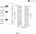
- a system bandwidth may be divided into four sub-bands, since a sub-band has a bandwidth of 20MHz.
- a system with a bandwidth of 80MHz may be divided into four sub-bands each with a bandwidth of 20MHz.
- each interlace includes m physical resource blocks (PRB), which are evenly spaced in a frequency domain, with indexes of ⁇ m, M+m, 2M+m, 3M+m, ... ⁇ , where M represents the number of interlaces.
- PRB physical resource blocks
- the bandwidth of the sub-band is 20MHz.
- One physical resource block includes 12 subcarriers in the frequency domain, and a sub-frame may include multiple RBs.
- One sub-band may include 10 clusters, namely Cluster0 to Cluster9.
- Each of the clusters may be composed of multiple interlaces.
- each of the Cluster0 to Cluster9 consists of 10 interlaces, namely interlace0 to interlace9.
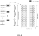
- FIG 2 is different from FIG 1 in that: in a case where the subcarrier spacing is 30KHz, one sub-band includes 10 clusters, but each of the clusters consists of 5 interlaces, i.e., interlace0 to interlace4.
- DCI 0_1 in a user search space includes a sub-band indicator field, which may indicate which sub-band is for uplink transmission.
- DCI 0_0 in a common search space does not include the sub-band indicator field, and the DCI 0_0 in the user search space does not necessarily include the sub-band indicator field.
- the DCI 0_0 in the common search space does not include the sub-band indicator field
- the following two schemes may be used.
- the DCI 0_0 in the user search space includes the sub-band indicator field, and thereby the terminal determines which sub-bands the terminal performs uplink transmission on according to the sub-band indicator field indicated by the base station.
- the DCI 0_0 in the user search space does not include the sub-band indicator field, and the terminal performs uplink transmission on all interlaces indicated in an uplink bandwidth part (BWP).
- BWP uplink bandwidth part
- scheme 1 since the protocol stipulates that the DCI 0_0 in the common search space does not include the sub-band indication field. In a case that the DCI 0_0 in the user search space includes the sub-band indication field, the terminal needs to distinguish whether a received DCI 0_0 is from the common search space or the user search space, and an implementation complexity may be increased. Moreover, scheme 1 does not solve how the terminal determines which sub-bands are for uplink transmission in a case that the DCI 0_0 in the common search space does not include the sub-band indication field.
- uplink data is to be transmitted on multiple sub-bands in a case that the uplink bandwidth includes multiple sub-bands, which means that the terminal needs to perform LBT on multiple sub-bands simultaneously.
- the terminal performs uplink transmission only after the LBT is successful in all the sub-bands, resulting in a decreased probability that the terminal wins in competition for an uplink channel.
- a method for uplink data transmission is provided according to an embodiment of the present disclosure.
- scheduling information does not include a sub-band indication field
- a sub-band for the uplink data transmission is obtained based on the sub-band corresponding to a configured Physical Uplink Control Channel (PUCCH) resource. Since succeed of LBT on all sub-bands is not a pre-condition for the terminal to perform uplink transmission, the probability of successfully occupying a channel for PUSCH transmission may be increased.
- the terminal does not need to distinguish whether the received uplink resource scheduling information is from the common search space or the user search space, the implementation complexity for the terminal may be reduced.
- a method for uplink data transmission is provided according to an embodiment of the present disclosure.
- the method may include the following steps 31 to 33.
- uplink resource scheduling information is received, where the uplink resource scheduling information includes frequency resource (resource in frequency domain) allocation information, and the frequency resource allocation information includes interlaced resource block indication information.
- the uplink resource scheduling information may be carried by DCI 0_0 or DCI 0_1, which is not limited.
- the interlaced resource block indication information is for indicating which interlace, within a bandwidth part (BWP) of the uplink transmission, may be used for the uplink transmission.
- BWP bandwidth part
- a specific frequency resource for the uplink transmission may be determined based on the interlaced resource block indication information.
- the specific frequency resource for the uplink transmission is an intersection of the sub-band for the uplink transmission and the resource indicated by the interlaced resource block indication information.
- a sub-band for the uplink transmission is determined based on the sub-band corresponding to a configured PUCCH resource, in response to the frequency resource allocation information not carrying sub-band indication information.
- the specific frequency resource for the uplink transmission may be determined directly based on the sub-band indicated by the sub-band indication information and the interlaced resource block indication information.
- the terminal may determine the sub-band for the uplink data transmission based on the sub-band corresponding to the configured PUCCH resource, that is, limit an interlaced resource block indicated in the interlaced resource block indication information to the sub-band corresponding to the PUCCH resource, so that the uplink transmission finally occurs on an intersection of the interlace indicated by the interlaced resource block indication information and the sub-band corresponding to the PUCCH resource.
- the base station may assign PUCCH resources of different terminals to different sub-bands to improve resource utilization.
- the resource utilization may be improved, and a probability of congestion on the sub-bands may be reduced.
- the sub-band corresponding to the PUCCH resource is in an idle state after transmitting scheduling information, some or all of the sub-bands corresponding to the PUCCH resource is used for the uplink data transmission, and the base station is not required to assign the sub-band for the uplink data transmission to the terminal.
- the resource utilization may be improved, and resource consumption of the sub-band required by the base station to send the uplink data transmission.
- one terminal in a cell may be configured with a single PUCCH resource, or may be configured with two or more PUCCH resources.
- the PUCCH resources may be distributed on a same sub-band or on different sub-bands. In other words, the quantity of sub-bands corresponding to the PUCCH resource(s) may be one, or two or more.
- the sub-band corresponding to the configured PUCCH resource may be directly determined as the sub-band for the uplink data transmission.
- a first preset sub-band may be determined as the sub-band for the uplink data transmission.
- the first preset sub-band may be set based on an actual requirement.
- the first preset sub-band may correspond to a PUCCH resource having a maximum index value among the sub-bands corresponding to the configured PUCCH resource. That is, the interlaced resource block indicated in the interlaced resource block indication information is limited within the sub-band corresponding to the PUCCH resource with the maximum index value. Thereby, the implementation complexity for the terminal may be reduced.
- the first preset sub-band may correspond to a PUCCH resource having a minimum index value among the sub-bands corresponding to the configured PUCCH resource. That is, the interlaced resource block indicated in the interlaced resource block instruction information is limited within the sub-band corresponding to the PUCCH resource with the minimum index value. Since the PUCCH resource with the minimum index value requires high reliability, the sub-band corresponding to such PUCCH resource is relatively reliable. Therefore, using such sub-band may increase a reliability of PUSCH transmission.
- the number of PUCCH resources configured in a cell is three, and index values of the PUCCH resources are PUCCH1, PUCCH2 and PUCCH3, respectively.
- the sub-band corresponding to PUCCH3 may be determined as the sub-band for uplink data transmission.
- the sub-band corresponding to PUCCH1 may be determined as the sub-band for the uplink data transmission.
- the first preset sub-band may have a maximum index value among the sub-bands corresponding to the configured PUCCH resource. That is, the interlaced resource block indicated in the interlaced resource block indication information is limited within the sub-band with the maximum index value. Thereby, the implementation complexity for the terminal is reduced.
- the number of sub-bands corresponding to the PUCCH resource configured in a cell is three, and index values of the sub-bands are sub-band 1, sub-band 2 and sub-band 3, respectively.
- the sub-band corresponding to sub-band 3 may be determined as the sub-band for uplink data transmission, or the sub-band corresponding to sub-band 1 may be determined as the sub-band for the uplink data transmission.
- the terminal may determine the sub-band for the uplink data transmission based on the sub-bands included in the current active BWP. That is to say, some or all of the sub-bands included in the current active BWP are determined as the sub-band for the uplink data transmission, that is, the interlaced resource block indicated in the interlaced resource block indication information is limited within some or all of sub-bands included in the current active BWP.
- the current active BWP may include a single sub-band, or two or more sub-bands.
- the sub-band included in the current active BWP may be directly determined as the sub-band for the uplink data transmission, in response to the current active BWP including a single sub-band. That is, the interlaced resource block indicated in the interlaced resource block indication information is limited within the single sub-band included in the current active BWP.
- a second preset sub-band may be determined as the sub-band for the uplink data transmission.
- the second preset sub-band may be configured based on an actual requirement.
- the second preset sub-band may have a maximum index value among the two or more sub-bands included in the current active BWP. That is, the interlaced resource block indicated in the interlaced resource block indication information is limited within the sub-band with the maximum index value in the current active BWP. Thereby the implementation complexity for the terminal is reduced, and a protocol complexity is reduced.
- the second preset sub-band may have a minimum index value among the two or more sub-bands included in the current active BWP. That is, the interlaced resource block indicated in the interlaced resource block indication information is limited within the sub-band with the minimum index value in the current active BWP. Thereby, the implementation complexity for the terminal is reduced, and the protocol complexity is reduced.
- the current active BWP includes three sub-bands, and index values of the sub-bands are sub-band 1, sub-band 2 and sub-band 3, respectively.
- the sub-band corresponding to sub-band 3 may be determined as the sub-band for the uplink data transmission.
- the sub-band corresponding to sub-band 1 may be determined as the sub-band for the uplink data transmission.
- the minimum index may be sub-band 0.
- another sub-band in the current active BWP may be determined as the sub-band for the uplink data transmission, which is not limited here.
- the terminal may determine the sub-band for the uplink data transmission based on the sub-band included in the current active BWP. That is to say, some or all of sub-bands included in the current active BWP are determine as sub-bands for the uplink data transmission, that is, the interlaced resource block indicated in the interlaced resource block indication information is limited within the some or all of the sub-bands included in the current active BWP.
- the current active BWP may include a single sub-band or two or more sub-bands.
- the sub-band included in the current active BWP in response to the current active BWP including a single sub-band, may be directly determined as the sub-band for the uplink data transmission. That is, the interlaced resource block indicated in the interlaced resource block indication information is limited within the single sub-band included in the current active BWP.
- a second preset sub-band in response to the current active BWP including two or more sub-bands, may be determined as the sub-band for the uplink data transmission.
- the second preset sub-band may be configured based on an actual requirement.
- the second preset sub-band may have a maximum index value among the two or more sub-bands included in the current active BWP. That is, the interlaced resource block indicated in the interlaced resource block indication information is limited within the sub-band with the maximum index value in the current active BWP. Thereby, the implementation complexity for the terminal is reduced, and the protocol complexity is reduced.
- the second preset sub-band may have a minimum index value among the two or more sub-bands included in the current active BWP. That is, the interlaced resource block indicated in the interlaced resource block indication information is limited within the sub-band with the minimum index value in the current active BWP. Thereby, the implementation complexity for the terminal is reduced, and the protocol complexity is reduced.
- the current active BWP includes three sub-bands, and index values of the sub-bands are sub-band 1, sub-band 2 and sub-band 3, respectively.
- the sub-band corresponding to sub-band 3 may be determined as the sub-band for the uplink data transmission.
- the sub-band corresponding to sub-band 1 may be determined as the sub-band for the uplink data transmission.
- the minimum index may be sub-band 0.
- another sub-band in the current active BWP may be determined as the sub-band for the uplink data transmission, which is not limited here.
- a process of determining the sub-band for the uplink data transmission based on the sub-band included in the current active BWP may include: determining, in the current active BWP, a sub-band in which a DCI carrying the uplink scheduling information is located as the sub-band for the uplink data transmission, in response to the uplink data transmission occurring within a channel occupation window obtained by a base station.
- the channel occupation window obtained by the base station refers to a transmission opportunity obtained by the base station.
- the base station schedules the uplink data transmission of the terminal through the DCI 0_0.
- the sub-band in which the DCI carrying the uplink scheduling information is basically idle.
- the sub-band in which the DCI carrying the uplink scheduling information is determined as the sub-band for the uplink data transmission, and the base station is not required to additionally assign an uplink transmission sub-band for the terminal, which not only improves a resource utilization efficiency, but also reduces resource consumption of the sub-band required by the base station to transmit the uplink data transmission.
- the terminal needs to perform a 16us or 25us LBT only once, which reduces the number of LBTs in a time domain and increases the probability of accessing a channel.
- a position of the sub-band carrying the DCI 0_0 in the frequency domain is in an uplink BWP, and the base station schedules an uplink transmission on the terminal through the DCI 0_0.
- the interlaced resource block indicated in the interlaced resource block indication information may be limited within the sub-band carrying the DCI 0_0.
- a position of the sub-band carrying the DCI 0_0 in the frequency domain is in an uplink BWP, and the base station schedules and uplink transmission on the terminal through the DCI 0_0.
- the interlaced resource block indicated in the interlaced resource block indication information may be limited within the sub-band whose index is equal to an index of the sub-band carrying the DCI 0_0. Thereby, the number of LBTs performed by the terminal may be reduced.
- the terminal may obtain the sub-band indication information and determine the sub-band for the uplink data transmission.
- the sub-band indication information is carried in high-level signaling.
- the terminal may send a request to the base station for acquiring the sub-band indication information.
- the base station may send the sub-band indication information to the terminal through high-level signaling.
- the high-level signaling may be a Radio Resource Control (RRC) signaling or a Media Access Control Layer Control Unit (MAC CE) signaling, which is not limited here.
- RRC Radio Resource Control
- MAC CE Media Access Control Layer Control Unit
- step 33 a resource for the uplink data transmission is determined, based on the sub-band for the uplink data transmission and the interlaced resource block indication information, and the uplink data transmission is performed.
- a resource block for the uplink transmission on the sub-band may be obtained based on the interlaced resource block indication information, and thereby the resource for the uplink transmission may be specifically determined.
- the method for uplink data transmission may be implemented through a software program running in a processor integrated inside a chip or chip module.
- the sub-band for uplink transmission may be determined and the uplink transmission may be performed in a case that the scheduling information does not include a sub-band indication field, and thereby the probability that a PUSCH transmission successfully competes for a channel is increased and the implementation complexity for the terminal is reduced.
- a terminal 40 is further provided according to an embodiment of the present disclosure.
- the terminal 40 may include a receiving unit 41, a first sub-band determination unit 42, and a data transmission unit 43.
- the receiving unit 41 is configured to receive uplink resource scheduling information.
- the uplink resource scheduling information includes frequency resource allocation information, and the frequency resource allocation information includes interlaced resource block indication information.
- the first sub-band determining unit 42 is configured to determine a sub-band for the uplink data transmission, based on the sub-band corresponding to a configured PUCCH resource, in response to the frequency resource allocation information not including sub-band indication information.
- the data transmission unit 43 is configured to determine a resource for the uplink data transmission, based on the sub-band for the uplink data transmission and the interlaced resource block indication information, and perform the uplink data transmission.
- the first sub-band determination unit 42 is configured to: determine the sub-band corresponding to the configured PUCCH resource as the sub-band for the uplink data transmission, in response to the configured PUCCH resource corresponding to a single sub-band; and determine a first preset sub-band of sub-bands corresponding to the configured PUCCH resource as the sub-band for the uplink data transmission, in response to the configured PUCCH resource corresponding to two or more sub-bands.
- the first preset sub-band corresponds to a PUCCH resource having a maximum index value or a minimum index value among the two or more sub-bands corresponding to the configured PUCCH resource.
- the first preset sub-band has a maximum index value or a minimum index value among the two or more sub-bands corresponding to the configured PUCCH resource.
- the terminal 40 may further include a second sub-band determination unit 44.
- the second sub-band determination unit 44 is configured to determine the sub-band for the uplink data transmission based on the sub-band in a current active BWP, in a case that no PUCCH resource is configured.
- the second sub-band determination unit 44 is configured to: determine the sub-band in the current active BWP as the sub-band for the uplink data transmission, in response to the current active BWP including a single sub-band; and determine a second preset sub-band of sub-bands in the current active BWP as the sub-band for the uplink data transmission, in response to the current active BWP including two or more sub-bands.
- the second preset sub-band has a maximum index value or a minimum index value among the two or more sub-bands in the current active BWP.
- the second sub-band determination unit 44 is configured to: determine, in the current active BWP, a sub-band in which a DCI carrying the uplink scheduling information is located as the sub-band for the uplink data transmission, in response to the uplink data transmission occurring within a channel occupation window obtained by a base station.
- the terminal 40 may further include a third sub-band determination unit 45.
- the third sub-band determination unit 45 is configured to: obtain the sub-band indication information and determine the sub-band for the uplink data transmission, in a case that no PUCCH resource is configured.
- the sub-band indication information is carried in high-level signaling.
- a computer readable storage medium is further provided in an embodiment of the present disclosure.
- the computer readable storage medium stores a computer program.
- the computer program is executed by a processor to perform steps of the method for uplink data transmission in the above embodiment, which is not repeated here.
- the computer readable storage medium may include a ROM, a RAM, a disk, a CD, or the like.
- each device and product described in the above embodiments may be software modules/units or hardware modules/units, or partially be software modules/units and partially be hardware modules/units.
- each module/unit included therein may be realized through circuits or other hardware; or at least some of the modules/units may be realized through software programs running on a processor integrated inside the chip, and the remaining (if any) modules/units may be realized through circuits or other hardware.
- each module/unit included therein may be realized through circuits or other hardware.
- Different modules/units may be disposed in a same component (such as a chip, a circuit module, or the like) or different components of the chip module; or at least some of the modules/units may be realized through software programs running on a processor integrated inside the chip module, and the remaining (if any) modules/units may be realized through circuits or other hardware. For each device or product applied to or integrated in a terminal, each module/unit may be realized through circuits or other hardware.
- modules/units may be disposed in a same component (such as a chip, a circuit module, or the like) or different components in the terminal; or at least some of the modules/units may be realized through software programs running on a processor integrated inside the terminal, and the remaining (if any) modules/units may be realized through circuits or other hardware.
Landscapes
- Engineering & Computer Science (AREA)
- Signal Processing (AREA)
- Computer Networks & Wireless Communication (AREA)
- Quality & Reliability (AREA)
- Mobile Radio Communication Systems (AREA)
Abstract
Description
- The present disclosure claims priority to
Chinese Patent Application No. 202010280890.1, titled "UPLINK DATA TRANSMISSION METHOD, TERMINAL, AND READABLE STORAGE MEDIUM", filed on April 10, 2020 - The present disclosure relates to the technical field of communications, and in particular to a method for uplink data transmission, a terminal, and a readable storage medium.
- In 5G New Radio (NR) unlicensed spectrum systems, a base station or terminal needs to perform Listen Before Talk (LBT) on a broadband before transmission. The base station or terminal performs LBT on N sub-bands (RB set), where N represents a ratio of a system bandwidth to a sub-band width (20MHz), that is,

- For uplink transmission, the terminal determines, based on scheduling information of the base station, which of the sub-bands the terminal needs to perform LBT on, and perform transmission on sub-bands indicated in the scheduling information only when the LBT is successful on all of the sub-bands indicated in the scheduling information. The scheduling information includes: uplink (UL) grant information, format 0_0 or 0_1 of Downlink Control Information (DCI) (that is, DCI 0_0 or DCI 0_1).
- An existing protocol specifies that DCI 0_1 in a UE Search Space (USS) includes a sub-band indicator field (RB-set indicator) indicating which sub-bands are for uplink transmission.
- However, the protocol now stipulates that the DCI 0_0 in a Common Search Space (CSS) does not include the sub-band indicator field, and the DCI 0_0 in the User Search Space does not necessarily include the sub-band indicator field. The terminal is unable to determine which sub-bands are for uplink transmission without the sub-band indication field.
- A problem to be solved by the present disclosure is: how to determine a sub-band for uplink transmission and perform the uplink transmission in a case that scheduling information does not include a sub-band indication field.
- To address the problem, a method for uplink data transmission is provided in the present disclosure. The method includes: receiving uplink resource scheduling information, where the uplink resource scheduling information includes frequency resource allocation information, and the frequency resource allocation information includes interlaced resource block indication information; determining a sub-band for the uplink data transmission based on a sub-band corresponding to a configured PUCCH resource, in response to the frequency resource allocation information not including sub-band indication information; determining a resource for the uplink data transmission, based on the sub-band for the uplink data transmission and the interlaced resource block indication information; and performing the uplink data transmission.
- In an embodiment, determining the sub-band for the uplink data transmission based on the sub-band corresponding to the configured PUCCH resource includes: determining a single sub-band corresponding to the configured PUCCH resource as the sub-band for the uplink data transmission, in response to the configured PUCCH resource corresponding to merely the single sub-band; and determining a first preset sub-band of two or more sub-bands corresponding to the configured PUCCH resource as the sub-band for the uplink data transmission, in response to the configured PUCCH resource corresponding to the two or more sub-bands.
- In an embodiment, the first preset sub-band corresponds to a PUCCH resource having a maximum index value or a minimum index value among the two or more sub-bands.
- In an embodiment, the first preset sub-band has a maximum index value or a minimum index value among the two or more sub-bands.
- In an embodiment, in response to no PUCCH resource being configured, the method further includes: determining the sub-band for the uplink data transmission based on a sub-band in a current active BWP.
- In an embodiment, determining the sub-band for the uplink data transmission based on the sub-band in the current active BWP includes: determining a single sub-band in the current active BWP as the sub-band for the uplink data transmission, in response to the current active BWP including merely the single sub-band; and determining a second preset sub-band of two or more sub-bands in the current active BWP as the sub-band for the uplink data transmission, in response to the current active BWP including the two or more sub-bands.
- In an embodiment, the second preset sub-band has a maximum index value or a minimum index value among the two or more sub-bands included in the current active BWP.
- In an embodiment, determining the sub-band for the uplink data transmission based on the sub-band in the current active BWP includes: determining, in the current active BWP, a sub-band in which a DCI carrying the uplink scheduling information is located as the sub-band for the uplink data transmission, in response to the uplink data transmission occurring within a channel occupation window obtained by a base station.
- In an embodiment, in response to no PUCCH resource being configured, the method further includes: obtaining the sub-band indication information, and determining the sub-band for the uplink data transmission. The sub-band indication information is carried in high-level signaling.
- A terminal is further provided in an embodiment of the present disclosure. The terminal includes: a receiving unit, configured to receive uplink resource scheduling information, where the uplink resource scheduling information includes frequency resource allocation information, and the frequency resource allocation information includes interlaced resource block indication information; a first sub-band determination unit, configured to determine a sub-band for the uplink data transmission based on a sub-band corresponding to a configured PUCCH resource, in response to the frequency resource allocation information not including sub-band indication information; and a data transmission unit, configured to determine a resource for the uplink data transmission, based on the sub-band for the uplink data transmission and the interlaced resource block indication information, and perform the uplink data transmission.
- In an embodiment, the first sub-band determination unit is configured to: determine a single sub-band corresponding to the configured PUCCH resource as the sub-band for the uplink data transmission, in response to the configured PUCCH resource corresponding to merely the single sub-band; and determine a first preset sub-band of sub-bands corresponding to the configured PUCCH resource as the sub-band for the uplink data transmission, in response to the configured PUCCH resource corresponding to the two or more sub-bands.
- In an embodiment, the first preset sub-band corresponds to a PUCCH resource with a maximum index value or a minimum index value among the two or more sub-bands corresponds to the configured PUCCH resource.
- In an embodiment, the first preset sub-band has a maximum index value or a minimum index value among the two or more sub-bands corresponding to the configured PUCCH resource.
- In an embodiment, the terminal further includes: a second sub-band determination unit, configured to determine the sub-band for the uplink data transmission based on a sub-band in a current active BWP, in response to no PUCCH resource being configured.
- In an embodiment, the second sub-band determination unit is configured to: determine a single sub-band in the current active BWP as the sub-band for the uplink data transmission, in response to the current active BWP including merely the single sub-band; and determine a second preset sub-band of two or more sub-bands in the current active BWP as the sub-band for the uplink data transmission, in response to the current active BWP including the two or more sub-bands.
- In an embodiment, the second preset sub-band has a maximum index value or a minimum index value among the two or more sub-bands in the current active BWP.
- In an embodiment, the second sub-band determination unit is configured to: determine, in the current active BWP, a sub-band in which a DCI carrying the uplink scheduling information is located as the sub-band for the uplink data transmission, in response to the uplink data transmission occurring within a channel occupation window obtained by a base station.
- In an embodiment, the terminal may further include: a third sub-band determination unit, configured to obtain the sub-band indication information and determine the sub-band for the uplink data transmission, in a case that no PUCCH resource is configured. The sub-band indication information is carried in high-level signaling.
- A computer readable storage medium storing a computer program is further provided in an embodiment of the present disclosure. The computer program when executed by a processor is configured to implement the method according to any of the above embodiments.
- Advantages of the technical solution compared with a conventional technology are described below.
- With the above solution, in a case that scheduling information does not include a sub-band indication field, the sub-band for the uplink data transmission is determined based on a sub-band corresponding to the configured PUCCH resource. The terminal does not need to perform uplink transmission under the condition that the LBT is successful on all sub-bands. Thereby, a probability that a PUSCH transmission successfully competes for a channel is increased. Moreover, the terminal does not need to distinguish whether the received uplink resource scheduling information comes from the common search space or the user search space. Thereby, an implementation complexity for the terminal may be reduced.
-
-
FIG 1 shows a sub-band resource diagram with a subcarrier interval of 15KHZ. -
FIG 2 shows a sub-band resource diagram with a subcarrier interval of 30 KHZ. -
FIG 3 shows a flow chart of a method for uplink data transmission according to an embodiment of the present disclosure. -
FIG 4 shows a schematic structural diagram of a terminal according to an embodiment of the present disclosure. - In a NR unlicensed spectrum system, a system bandwidth may be divided into four sub-bands, since a sub-band has a bandwidth of 20MHz. For example, a system with a bandwidth of 80MHz may be divided into four sub-bands each with a bandwidth of 20MHz.
- In the NR unlicensed spectrum system, an interlace structure may be adopted for uplink transmission. Each interlace includes m physical resource blocks (PRB), which are evenly spaced in a frequency domain, with indexes of {m, M+m, 2M+m, 3M+m, ...}, where M represents the number of interlaces. A specific definition thereof may refer to the description of the 38.211 4.4.4.6 in the 3GPP protocol.
- For example, reference is made to
FIG 1 . The bandwidth of the sub-band is 20MHz. One physical resource block includes 12 subcarriers in the frequency domain, and a sub-frame may include multiple RBs. One sub-band may include 10 clusters, namely Cluster0 to Cluster9. Each of the clusters may be composed of multiple interlaces. For example, each of the Cluster0 to Cluster9 consists of 10 interlaces, namely interlace0 to interlace9. In a case where a subcarrier spacing (SCS) is 15KHz, M=10, that is, the indexes of the physical resource blocks in each interlace are {m, 10+m, 20+m, 30+m,... }. - Reference is made to
FIG 2. FIG 2 is different fromFIG 1 in that: in a case where the subcarrier spacing is 30KHz, one sub-band includes 10 clusters, but each of the clusters consists of 5 interlaces, i.e., interlace0 to interlace4. In the case that the subcarrier spacing is 30KHz, M=5, that is, the indexes of the PRBs in each interlace are {m, 5+m, 10+m, 15+m, ...}. - In the current protocol, DCI 0_1 in a user search space includes a sub-band indicator field, which may indicate which sub-band is for uplink transmission. DCI 0_0 in a common search space does not include the sub-band indicator field, and the DCI 0_0 in the user search space does not necessarily include the sub-band indicator field.
- In a case that the DCI 0_0 in the common search space does not include the sub-band indicator field, in order to enable the terminal to determine the sub-band for uplink transmission and perform uplink transmission, the following two schemes may be used.
- In
scheme 1, the DCI 0_0 in the user search space includes the sub-band indicator field, and thereby the terminal determines which sub-bands the terminal performs uplink transmission on according to the sub-band indicator field indicated by the base station. - In
scheme 2, the DCI 0_0 in the user search space does not include the sub-band indicator field, and the terminal performs uplink transmission on all interlaces indicated in an uplink bandwidth part (BWP). - For
scheme 1, since the protocol stipulates that the DCI 0_0 in the common search space does not include the sub-band indication field. In a case that the DCI 0_0 in the user search space includes the sub-band indication field, the terminal needs to distinguish whether a received DCI 0_0 is from the common search space or the user search space, and an implementation complexity may be increased. Moreover,scheme 1 does not solve how the terminal determines which sub-bands are for uplink transmission in a case that the DCI 0_0 in the common search space does not include the sub-band indication field. - For
scheme 2, uplink data is to be transmitted on multiple sub-bands in a case that the uplink bandwidth includes multiple sub-bands, which means that the terminal needs to perform LBT on multiple sub-bands simultaneously. The terminal performs uplink transmission only after the LBT is successful in all the sub-bands, resulting in a decreased probability that the terminal wins in competition for an uplink channel. - Aiming at the above problems, a method for uplink data transmission is provided according to an embodiment of the present disclosure. In a case that scheduling information does not include a sub-band indication field, a sub-band for the uplink data transmission is obtained based on the sub-band corresponding to a configured Physical Uplink Control Channel (PUCCH) resource. Since succeed of LBT on all sub-bands is not a pre-condition for the terminal to perform uplink transmission, the probability of successfully occupying a channel for PUSCH transmission may be increased. Moreover, since the terminal does not need to distinguish whether the received uplink resource scheduling information is from the common search space or the user search space, the implementation complexity for the terminal may be reduced.
- In order to make the objectives, characteristics and advantages of the present disclosure more apparent and easy to understand, the following embodiments of the present disclosure are illustrated in detail in combination with the drawings.
- Reference is made to
FIG 3 . A method for uplink data transmission is provided according to an embodiment of the present disclosure. The method may include the followingsteps 31 to 33. - In
step 31, uplink resource scheduling information is received, where the uplink resource scheduling information includes frequency resource (resource in frequency domain) allocation information, and the frequency resource allocation information includes interlaced resource block indication information. - In an embodiment, the uplink resource scheduling information may be carried by DCI 0_0 or DCI 0_1, which is not limited.
- In an embodiment, the interlaced resource block indication information is for indicating which interlace, within a bandwidth part (BWP) of the uplink transmission, may be used for the uplink transmission. After a sub-band for the uplink transmission is determined, a specific frequency resource for the uplink transmission may be determined based on the interlaced resource block indication information. The specific frequency resource for the uplink transmission is an intersection of the sub-band for the uplink transmission and the resource indicated by the interlaced resource block indication information.
- In
step 32, a sub-band for the uplink transmission is determined based on the sub-band corresponding to a configured PUCCH resource, in response to the frequency resource allocation information not carrying sub-band indication information. - In an embodiment, in response to the frequency resource allocation information carrying the sub-band indication information, the specific frequency resource for the uplink transmission may be determined directly based on the sub-band indicated by the sub-band indication information and the interlaced resource block indication information.
- In a case that the frequency resource allocation information does not carry the sub-band indication information, for example, the uplink scheduling information is DCI 0_0 in the common search space or DCI 0_0 in the user search space. In such case, the terminal may determine the sub-band for the uplink data transmission based on the sub-band corresponding to the configured PUCCH resource, that is, limit an interlaced resource block indicated in the interlaced resource block indication information to the sub-band corresponding to the PUCCH resource, so that the uplink transmission finally occurs on an intersection of the interlace indicated by the interlaced resource block indication information and the sub-band corresponding to the PUCCH resource.
- The base station may assign PUCCH resources of different terminals to different sub-bands to improve resource utilization. In a case that the PUSCH transmission scheduled by DCI 0_0 is bound with a PUCCH resource assignment, the resource utilization may be improved, and a probability of congestion on the sub-bands may be reduced.
- In addition, since the sub-band corresponding to the PUCCH resource is in an idle state after transmitting scheduling information, some or all of the sub-bands corresponding to the PUCCH resource is used for the uplink data transmission, and the base station is not required to assign the sub-band for the uplink data transmission to the terminal. Thereby, the resource utilization may be improved, and resource consumption of the sub-band required by the base station to send the uplink data transmission.
- In an embodiment, one terminal in a cell may be configured with a single PUCCH resource, or may be configured with two or more PUCCH resources. The PUCCH resources may be distributed on a same sub-band or on different sub-bands. In other words, the quantity of sub-bands corresponding to the PUCCH resource(s) may be one, or two or more.
- In a case that the configured PUCCH resource corresponds to a single sub-band, according to an embodiment of the present disclosure, the sub-band corresponding to the configured PUCCH resource may be directly determined as the sub-band for the uplink data transmission.
- In a case that the configured PUCCH resource corresponds to two or more sub-bands, a first preset sub-band may be determined as the sub-band for the uplink data transmission. The first preset sub-band may be set based on an actual requirement.
- In an embodiment of the present disclosure, the first preset sub-band may correspond to a PUCCH resource having a maximum index value among the sub-bands corresponding to the configured PUCCH resource. That is, the interlaced resource block indicated in the interlaced resource block indication information is limited within the sub-band corresponding to the PUCCH resource with the maximum index value. Thereby, the implementation complexity for the terminal may be reduced.
- In another embodiment of the present disclosure, the first preset sub-band may correspond to a PUCCH resource having a minimum index value among the sub-bands corresponding to the configured PUCCH resource. That is, the interlaced resource block indicated in the interlaced resource block instruction information is limited within the sub-band corresponding to the PUCCH resource with the minimum index value. Since the PUCCH resource with the minimum index value requires high reliability, the sub-band corresponding to such PUCCH resource is relatively reliable. Therefore, using such sub-band may increase a reliability of PUSCH transmission.
- For example, the number of PUCCH resources configured in a cell is three, and index values of the PUCCH resources are PUCCH1, PUCCH2 and PUCCH3, respectively. In such case, the sub-band corresponding to PUCCH3 may be determined as the sub-band for uplink data transmission. The sub-band corresponding to PUCCH1 may be determined as the sub-band for the uplink data transmission.
- In another embodiment of the present disclosure, the first preset sub-band may have a maximum index value among the sub-bands corresponding to the configured PUCCH resource. That is, the interlaced resource block indicated in the interlaced resource block indication information is limited within the sub-band with the maximum index value. Thereby, the implementation complexity for the terminal is reduced.
- For example, it is assumed that the number of sub-bands corresponding to the PUCCH resource configured in a cell is three, and index values of the sub-bands are sub-band 1,
sub-band 2 andsub-band 3, respectively. In this case, the sub-band corresponding to sub-band 3 may be determined as the sub-band for uplink data transmission, or the sub-band corresponding to sub-band 1 may be determined as the sub-band for the uplink data transmission. - In an embodiment, in a case that no PUCCH resource is configured in a cell, the terminal may determine the sub-band for the uplink data transmission based on the sub-bands included in the current active BWP. That is to say, some or all of the sub-bands included in the current active BWP are determined as the sub-band for the uplink data transmission, that is, the interlaced resource block indicated in the interlaced resource block indication information is limited within some or all of sub-bands included in the current active BWP.
- In embodiments, the current active BWP may include a single sub-band, or two or more sub-bands. According to an embodiment of the present disclosure, the sub-band included in the current active BWP may be directly determined as the sub-band for the uplink data transmission, in response to the current active BWP including a single sub-band. That is, the interlaced resource block indicated in the interlaced resource block indication information is limited within the single sub-band included in the current active BWP.
- According to an embodiment of the present disclosure, in a case that the current active BWP includes two or more sub-bands, a second preset sub-band may be determined as the sub-band for the uplink data transmission. The second preset sub-band may be configured based on an actual requirement.
- In an embodiment of the present disclosure, the second preset sub-band may have a maximum index value among the two or more sub-bands included in the current active BWP. That is, the interlaced resource block indicated in the interlaced resource block indication information is limited within the sub-band with the maximum index value in the current active BWP. Thereby the implementation complexity for the terminal is reduced, and a protocol complexity is reduced.
- In another embodiment of the present disclosure, the second preset sub-band may have a minimum index value among the two or more sub-bands included in the current active BWP. That is, the interlaced resource block indicated in the interlaced resource block indication information is limited within the sub-band with the minimum index value in the current active BWP. Thereby, the implementation complexity for the terminal is reduced, and the protocol complexity is reduced.
- For example, it is assumed that the current active BWP includes three sub-bands, and index values of the sub-bands are sub-band 1,
sub-band 2 andsub-band 3, respectively. In such case, the sub-band corresponding to sub-band 3 may be determined as the sub-band for the uplink data transmission. The sub-band corresponding to sub-band 1 may be determined as the sub-band for the uplink data transmission. - In some embodiments, the minimum index may be sub-band 0. In other embodiments, another sub-band in the current active BWP may be determined as the sub-band for the uplink data transmission, which is not limited here.
- In an embodiment, in a case that a PUCCH resource is configured in a cell, the terminal may determine the sub-band for the uplink data transmission based on the sub-band included in the current active BWP. That is to say, some or all of sub-bands included in the current active BWP are determine as sub-bands for the uplink data transmission, that is, the interlaced resource block indicated in the interlaced resource block indication information is limited within the some or all of the sub-bands included in the current active BWP.
- In an embodiment, the current active BWP may include a single sub-band or two or more sub-bands. According to an embodiment, in response to the current active BWP including a single sub-band, the sub-band included in the current active BWP may be directly determined as the sub-band for the uplink data transmission. That is, the interlaced resource block indicated in the interlaced resource block indication information is limited within the single sub-band included in the current active BWP.
- In an embodiment of the present disclosure, in response to the current active BWP including two or more sub-bands, a second preset sub-band may be determined as the sub-band for the uplink data transmission. The second preset sub-band may be configured based on an actual requirement.
- In an embodiment of the present disclosure, the second preset sub-band may have a maximum index value among the two or more sub-bands included in the current active BWP. That is, the interlaced resource block indicated in the interlaced resource block indication information is limited within the sub-band with the maximum index value in the current active BWP. Thereby, the implementation complexity for the terminal is reduced, and the protocol complexity is reduced.
- In another embodiment of the present disclosure, the second preset sub-band may have a minimum index value among the two or more sub-bands included in the current active BWP. That is, the interlaced resource block indicated in the interlaced resource block indication information is limited within the sub-band with the minimum index value in the current active BWP. Thereby, the implementation complexity for the terminal is reduced, and the protocol complexity is reduced.
- For example, it is assumed that the current active BWP includes three sub-bands, and index values of the sub-bands are sub-band 1,
sub-band 2 andsub-band 3, respectively. In such case, the sub-band corresponding to sub-band 3 may be determined as the sub-band for the uplink data transmission. The sub-band corresponding to sub-band 1 may be determined as the sub-band for the uplink data transmission. - In some embodiments, the minimum index may be sub-band 0. In other embodiments, another sub-band in the current active BWP may be determined as the sub-band for the uplink data transmission, which is not limited here.
- In an embodiment of the present disclosure, a process of determining the sub-band for the uplink data transmission based on the sub-band included in the current active BWP may include: determining, in the current active BWP, a sub-band in which a DCI carrying the uplink scheduling information is located as the sub-band for the uplink data transmission, in response to the uplink data transmission occurring within a channel occupation window obtained by a base station.
- In an embodiment, the channel occupation window obtained by the base station refers to a transmission opportunity obtained by the base station. Within the channel occupation window obtained by the base station, the base station schedules the uplink data transmission of the terminal through the DCI 0_0. After the terminal receives the scheduling information and determines to send a PUSCH, the sub-band in which the DCI carrying the uplink scheduling information is basically idle. In such case, the sub-band in which the DCI carrying the uplink scheduling information is determined as the sub-band for the uplink data transmission, and the base station is not required to additionally assign an uplink transmission sub-band for the terminal, which not only improves a resource utilization efficiency, but also reduces resource consumption of the sub-band required by the base station to transmit the uplink data transmission. In addition, in a case that the PUSCH transmission occurs in the sub-band where the scheduling DCI is located, the terminal needs to perform a 16us or 25us LBT only once, which reduces the number of LBTs in a time domain and increases the probability of accessing a channel.
- In an embodiment of the present disclosure, a position of the sub-band carrying the DCI 0_0 in the frequency domain is in an uplink BWP, and the base station schedules an uplink transmission on the terminal through the DCI 0_0. In a case that the uplink data transmission occurs within the channel occupation window obtained by the base station, the interlaced resource block indicated in the interlaced resource block indication information may be limited within the sub-band carrying the DCI 0_0.
- In another embodiment of the present disclosure, a position of the sub-band carrying the DCI 0_0 in the frequency domain is in an uplink BWP, and the base station schedules and uplink transmission on the terminal through the DCI 0_0. In a case that the uplink transmission occurs outside the channel occupation window obtained by the base station, the interlaced resource block indicated in the interlaced resource block indication information may be limited within the sub-band whose index is equal to an index of the sub-band carrying the DCI 0_0. Thereby, the number of LBTs performed by the terminal may be reduced.
- In an embodiment, in a case that no PUCCH resource is configured in a cell, the terminal may obtain the sub-band indication information and determine the sub-band for the uplink data transmission. The sub-band indication information is carried in high-level signaling.
- For example, the terminal may send a request to the base station for acquiring the sub-band indication information. After receiving the request, the base station may send the sub-band indication information to the terminal through high-level signaling. The high-level signaling may be a Radio Resource Control (RRC) signaling or a Media Access Control Layer Control Unit (MAC CE) signaling, which is not limited here.
- In
step 33, a resource for the uplink data transmission is determined, based on the sub-band for the uplink data transmission and the interlaced resource block indication information, and the uplink data transmission is performed. - In an embodiment, after the sub-band for the uplink data transmission is determined, a resource block for the uplink transmission on the sub-band may be obtained based on the interlaced resource block indication information, and thereby the resource for the uplink transmission may be specifically determined.
- It should be understood that, in the embodiments, the method for uplink data transmission may be implemented through a software program running in a processor integrated inside a chip or chip module.
- It can be seen from the above that with the method for uplink data transmission, the sub-band for uplink transmission may be determined and the uplink transmission may be performed in a case that the scheduling information does not include a sub-band indication field, and thereby the probability that a PUSCH transmission successfully competes for a channel is increased and the implementation complexity for the terminal is reduced.
- In order to enable better understanding and implementation of the present disclosure for those skilled in the art, a device and a computer readable storage medium corresponding to the above method are described in detail below.
- Reference is made to
FIG 4 . A terminal 40 is further provided according to an embodiment of the present disclosure. The terminal 40 may include a receivingunit 41, a firstsub-band determination unit 42, and adata transmission unit 43. - The receiving
unit 41 is configured to receive uplink resource scheduling information. The uplink resource scheduling information includes frequency resource allocation information, and the frequency resource allocation information includes interlaced resource block indication information. - The first
sub-band determining unit 42 is configured to determine a sub-band for the uplink data transmission, based on the sub-band corresponding to a configured PUCCH resource, in response to the frequency resource allocation information not including sub-band indication information. - The
data transmission unit 43 is configured to determine a resource for the uplink data transmission, based on the sub-band for the uplink data transmission and the interlaced resource block indication information, and perform the uplink data transmission. - In an embodiment of the present disclosure, the first
sub-band determination unit 42 is configured to: determine the sub-band corresponding to the configured PUCCH resource as the sub-band for the uplink data transmission, in response to the configured PUCCH resource corresponding to a single sub-band; and determine a first preset sub-band of sub-bands corresponding to the configured PUCCH resource as the sub-band for the uplink data transmission, in response to the configured PUCCH resource corresponding to two or more sub-bands. - In an embodiment of the present disclosure, the first preset sub-band corresponds to a PUCCH resource having a maximum index value or a minimum index value among the two or more sub-bands corresponding to the configured PUCCH resource.
- In an embodiment of the present disclosure, the first preset sub-band has a maximum index value or a minimum index value among the two or more sub-bands corresponding to the configured PUCCH resource.
- In an embodiment of the present disclosure, the terminal 40 may further include a second
sub-band determination unit 44. The secondsub-band determination unit 44 is configured to determine the sub-band for the uplink data transmission based on the sub-band in a current active BWP, in a case that no PUCCH resource is configured. - In an embodiment of the present disclosure, the second
sub-band determination unit 44 is configured to: determine the sub-band in the current active BWP as the sub-band for the uplink data transmission, in response to the current active BWP including a single sub-band; and determine a second preset sub-band of sub-bands in the current active BWP as the sub-band for the uplink data transmission, in response to the current active BWP including two or more sub-bands. - In an embodiment of the present disclosure, the second preset sub-band has a maximum index value or a minimum index value among the two or more sub-bands in the current active BWP.
- In an embodiment of the present disclosure, the second
sub-band determination unit 44 is configured to: determine, in the current active BWP, a sub-band in which a DCI carrying the uplink scheduling information is located as the sub-band for the uplink data transmission, in response to the uplink data transmission occurring within a channel occupation window obtained by a base station. - In an embodiment of the present disclosure, the terminal 40 may further include a third
sub-band determination unit 45. The thirdsub-band determination unit 45 is configured to: obtain the sub-band indication information and determine the sub-band for the uplink data transmission, in a case that no PUCCH resource is configured. The sub-band indication information is carried in high-level signaling. - Detailed functions of component units of the terminal of embodiments of the present disclosure may be referred to the description of corresponding parts of the data transmission method in the above embodiments of the present disclosure, which is not repeated here.
- A computer readable storage medium is further provided in an embodiment of the present disclosure. The computer readable storage medium stores a computer program. The computer program is executed by a processor to perform steps of the method for uplink data transmission in the above embodiment, which is not repeated here.
- In an embodiment, the computer readable storage medium may include a ROM, a RAM, a disk, a CD, or the like.
- The modules/units of each device and product described in the above embodiments may be software modules/units or hardware modules/units, or partially be software modules/units and partially be hardware modules/units. For example, for each device or product applied to or integrated into a chip, each module/unit included therein may be realized through circuits or other hardware; or at least some of the modules/units may be realized through software programs running on a processor integrated inside the chip, and the remaining (if any) modules/units may be realized through circuits or other hardware. For each device or product applied to or integrated into a chip module, each module/unit included therein may be realized through circuits or other hardware. Different modules/units may be disposed in a same component (such as a chip, a circuit module, or the like) or different components of the chip module; or at least some of the modules/units may be realized through software programs running on a processor integrated inside the chip module, and the remaining (if any) modules/units may be realized through circuits or other hardware. For each device or product applied to or integrated in a terminal, each module/unit may be realized through circuits or other hardware. Different modules/units may be disposed in a same component (such as a chip, a circuit module, or the like) or different components in the terminal; or at least some of the modules/units may be realized through software programs running on a processor integrated inside the terminal, and the remaining (if any) modules/units may be realized through circuits or other hardware.
- Although the present disclosure is disclosed as above, the present disclosure is not limited thereto. Various changes and modifications can be made by those skilled in the art without departing away from the spirit and scope of the present disclosure. Therefore, the protection scope of the present disclosure should be determined based on the scope defined by the claim.
Claims (19)
- A method for uplink data transmission, comprising:receiving uplink resource scheduling information, wherein the uplink resource scheduling information comprises frequency resource allocation information, and the frequency resource allocation information comprises interlaced resource block indication information;determining a sub-band for the uplink data transmission based on a sub-band corresponding to a configured physical uplink control channel (PUCCH) resource, in response to the frequency resource allocation information not comprising sub-band indication information;determining a resource for the uplink data transmission, based on the sub-band for the uplink data transmission and the interlaced resource block indication information, andperforming the uplink data transmission.
- The method according to claim 1, wherein determining the sub-band for the uplink data transmission based on the sub-band corresponding to the configured PUCCH resource comprises:determining a single sub-band corresponding to the configured PUCCH resource as the sub-band for the uplink data transmission, in response to the configured PUCCH resource corresponding to merely the single sub-band; anddetermining a first preset sub-band of two or more sub-bands corresponding to the configured PUCCH resource as the sub-band for the uplink data transmission, in response to the configured PUCCH resource corresponding to the two or more sub-bands.
- The method according to claim 2, wherein the first preset sub-band corresponds to a PUCCH resource having a maximum index value or a minimum index value among the two or more sub-bands.
- The method according to claim 2, wherein the first preset sub-band has a maximum index value or a minimum index value among the two or more sub-bands.
- The method according to claim 1, wherein in response to no PUCCH resource being configured, the method further comprises:
determining the sub-band for the uplink data transmission based on a sub-band in a current active bandwidth part (BWP). - The method according to claim 5, wherein determining the sub-band for the uplink data transmission based on the sub-band in the current active BWP comprises:determining a single sub-band in the current active BWP as the sub-band for the uplink data transmission, in response to the current active BWP comprising merely the single sub-band; anddetermining a second preset sub-band of two or more sub-bands in the current active BWP as the sub-band for the uplink data transmission, in response to the current active BWP comprising the two or more sub-bands.
- The method according to claim 6, wherein the second preset sub-band has a maximum index value or a minimum index value among the two or more sub-bands.
- The method according to claim 5, wherein determining the sub-band for the uplink data transmission based on the sub-band in the current active BWP comprises:
determining, in the current active BWP, a sub-band in which a DCI carrying the uplink scheduling information is located as the sub-band for the uplink data transmission, in response to the uplink data transmission occurring within a channel occupation window obtained by a base station. - The method according to claim 1, wherein in response to no PUCCH resource being configured, the method further comprises:obtaining the sub-band indication information, anddetermining the sub-band for the uplink data transmission, whereinthe sub-band indication information is carried in high-level signaling.
- A terminal, comprising:a receiving unit, configured to receive uplink resource scheduling information, wherein the uplink resource scheduling information comprises frequency domain resource assignment information, and the frequency domain resource assignment information comprises interlaced resource block indication information;a first sub-band determination unit, configured to determine a sub-band for the uplink data transmission based on the sub-band corresponding to a configured PUCCH resource, in response to the frequency domain resource assignment information not comprising sub-band indication information; anda data transmission unit, configured to determine a resource for the uplink data transmission, based on the sub-band for the uplink data transmission and the interlaced resource block indication information, and perform the uplink data transmission.
- The terminal according to claim 10, wherein the first sub-band determination unit is configured to:determine a single sub-band corresponding to the configured PUCCH resource as the sub-band for the uplink data transmission, in response to the configured PUCCH resource corresponding to merely the single sub-band; anddetermine a first preset sub-band of two or more sub-bands corresponding to the configured PUCCH resource as the sub-band for the uplink data transmission, in response to the configured PUCCH resource corresponding to the two or more sub-bands.
- The terminal according to claim 11, wherein the first preset sub-band corresponds to a PUCCH resource having a maximum index value or a minimum index value among the two or more sub-bands.
- The terminal according to claim 11, wherein the first preset sub-band has a maximum index value or a minimum index value among the two or more sub-bands.
- The terminal according to claim 10, further comprising:
a second sub-band determination unit, configured to determine the sub-band for the uplink data transmission based on the sub-band in a current active BWP, in response to no PUCCH resource being configured. - The terminal according to claim 14, wherein the second sub-band determination unit is configured to:determine a single sub-band in the current active BWP as the sub-band for the uplink data transmission, in response to the current active BWP comprising merely the single sub-band; anddetermine a second preset sub-band of two or more sub-bands in the current active BWP as the sub-band for the uplink data transmission, in response to the current active BWP comprising the two or more sub-bands.
- The terminal according to claim 15, wherein the second preset sub-band has a maximum index value or a minimum index value among the two or more sub-bands.
- The terminal according to claim 14, wherein the second sub-band determination unit is configured to:
determine, in the current active BWP, a sub-band in which a DCI carrying the uplink scheduling information is located as the sub-band for the uplink data transmission, in response to the uplink data transmission occurring within a channel occupation window obtained by a base station. - The terminal according to claim 10, further comprising:a third sub-band determination unit, configured to obtain the sub-band indication information and determine the sub-band for the uplink data transmission, in response to no PUCCH resource being configured, whereinthe sub-band indication information is carried in high-level signaling.
- A computer-readable storage medium storing a computer program, wherein the computer program when executed by a processor is configured to implement the method according to any one of claims 1 to 9.
Applications Claiming Priority (2)
| Application Number | Priority Date | Filing Date | Title |
|---|---|---|---|
| CN202010280890.1A CN113518390B (en) | 2020-04-10 | 2020-04-10 | Uplink data transmission method, terminal and readable storage medium |
| PCT/CN2021/084913 WO2021204055A1 (en) | 2020-04-10 | 2021-04-01 | Uplink data transmission method, terminal, and readable storage medium |
Publications (2)
| Publication Number | Publication Date |
|---|---|
| EP4135245A1 true EP4135245A1 (en) | 2023-02-15 |
| EP4135245A4 EP4135245A4 (en) | 2023-11-01 |
Family
ID=78023698
Family Applications (1)
| Application Number | Title | Priority Date | Filing Date |
|---|---|---|---|
| EP21783937.2A Withdrawn EP4135245A4 (en) | 2020-04-10 | 2021-04-01 | UPLINK DATA TRANSMISSION METHOD, TERMINAL AND READABLE STORAGE MEDIUM |
Country Status (4)
| Country | Link |
|---|---|
| US (1) | US12520303B1 (en) |
| EP (1) | EP4135245A4 (en) |
| CN (2) | CN113518390B (en) |
| WO (1) | WO2021204055A1 (en) |
Families Citing this family (3)
| Publication number | Priority date | Publication date | Assignee | Title |
|---|---|---|---|---|
| CN113518390B (en) * | 2020-04-10 | 2022-09-09 | 展讯通信(上海)有限公司 | Uplink data transmission method, terminal and readable storage medium |
| CN117560125A (en) * | 2022-08-02 | 2024-02-13 | 大唐移动通信设备有限公司 | Frequency domain resource determination method, indication method, device, terminal and network equipment |
| CN119834940B (en) * | 2024-04-10 | 2025-12-19 | 荣耀终端股份有限公司 | A method and apparatus for a node used in wireless communication |
Family Cites Families (20)
| Publication number | Priority date | Publication date | Assignee | Title |
|---|---|---|---|---|
| US10630433B2 (en) * | 2015-12-11 | 2020-04-21 | Lg Electronics Inc. | Method for transmitting uplink signal and apparatus therefor |
| KR102742239B1 (en) * | 2016-02-03 | 2024-12-13 | 삼성전자주식회사 | Method and device for setting reference signals and generating channel information in mobile communication systems |
| CN108289335B (en) * | 2017-01-10 | 2023-07-14 | 中兴通讯股份有限公司 | Data transmission method and device, terminal |
| EP3595199B1 (en) * | 2017-04-14 | 2021-06-16 | LG Electronics Inc. | Method and apparatus for performing initial connection in wireless communication system |
| CN108810905B (en) | 2017-05-04 | 2023-10-24 | 华为技术有限公司 | Methods and devices for transmitting uplink channels and methods and devices for transmitting downlink channels |
| US11418368B2 (en) * | 2017-09-28 | 2022-08-16 | Lg Electronics Inc. | Method for performing uplink transmission in wireless communication system and apparatus therefor |
| US11064434B2 (en) * | 2017-10-31 | 2021-07-13 | Asustek Computer Inc. | Methods for performing communication for a cell |
| US11678333B2 (en) * | 2017-11-03 | 2023-06-13 | Qualcomm Incorporated | Methods and apparatus for bandwidth part enhancement |
| CN108882376B (en) * | 2017-11-10 | 2020-01-17 | 华为技术有限公司 | A communication method, device and system |
| KR20200005456A (en) * | 2018-07-06 | 2020-01-15 | 주식회사 케이티 | Methods for transmitting an uplink data in Unlicensed bandwidth and Apparatuses thereof |
| CN110740018B (en) * | 2018-07-18 | 2021-12-14 | 维沃移动通信有限公司 | Scheduling method, listening method and apparatus on unlicensed frequency band |
| CN110830194B (en) * | 2018-08-08 | 2020-10-30 | 北京紫光展锐通信技术有限公司 | Indication and determination method of uplink channel resource, base station, terminal and medium |
| CN110830218B (en) * | 2018-08-10 | 2022-03-22 | 展讯通信(上海)有限公司 | User equipment and data transmission method and device thereof |
| KR102408453B1 (en) * | 2018-08-10 | 2022-06-15 | 주식회사 케이티 | Method and apparatus for transmitting and receiving data in unlicensed band |
| CN110831024B (en) * | 2018-08-10 | 2021-06-18 | 展讯通信(上海)有限公司 | LBT method and apparatus for unlicensed spectrum, storage medium, terminal, base station |
| CN116707717B (en) * | 2018-09-27 | 2026-03-31 | 北京三星通信技术研究有限公司 | Uplink signal transmission method and apparatus |
| CN111585730B (en) * | 2019-02-15 | 2021-10-15 | 华为技术有限公司 | Transmission method and communication device |
| US11722255B2 (en) * | 2019-03-26 | 2023-08-08 | Kt Corporation | Method and apparatus for transmitting and receiving sidelink HARQ feedback information |
| CN120415639A (en) * | 2019-03-29 | 2025-08-01 | 中兴通讯股份有限公司 | Communication method, device, communication equipment and storage medium |
| CN113518390B (en) * | 2020-04-10 | 2022-09-09 | 展讯通信(上海)有限公司 | Uplink data transmission method, terminal and readable storage medium |
-
2020
- 2020-04-10 CN CN202010280890.1A patent/CN113518390B/en active Active
- 2020-04-10 CN CN202210901223.XA patent/CN115278785A/en active Pending
-
2021
- 2021-04-01 WO PCT/CN2021/084913 patent/WO2021204055A1/en not_active Ceased
- 2021-04-01 EP EP21783937.2A patent/EP4135245A4/en not_active Withdrawn
-
2022
- 2022-10-10 US US17/962,833 patent/US12520303B1/en active Active
Also Published As
| Publication number | Publication date |
|---|---|
| CN113518390B (en) | 2022-09-09 |
| EP4135245A4 (en) | 2023-11-01 |
| US12520303B1 (en) | 2026-01-06 |
| CN115278785A (en) | 2022-11-01 |
| WO2021204055A1 (en) | 2021-10-14 |
| CN113518390A (en) | 2021-10-19 |
Similar Documents
| Publication | Publication Date | Title |
|---|---|---|
| EP3836468B1 (en) | Uplink channel resource determination method, and terminal | |
| US11337244B2 (en) | Scheduling subband allocation method and apparatus, and device and readable storage medium | |
| US11395291B2 (en) | Allocating transmission resources in communication networks that provide low latency services | |
| US12520303B1 (en) | Uplink data transmission method, terminal, and readable storage medium | |
| EP3592073B1 (en) | Resource scheduling method and device | |
| EP3937519B1 (en) | Communication method and apparatus | |
| CN106954277B (en) | Scheduling request processing method and device | |
| JP2020536419A (en) | Resource allocation identification method, resource allocation instruction method, terminals and network side devices | |
| US20200045733A1 (en) | Uplink Scheduling For NR-U | |
| JP2011525748A (en) | Signaling resource allocation in telecommunication networks | |
| CN113056887B (en) | Method and apparatus for transmitting or receiving wireless signals in a wireless communication system | |
| US12335959B2 (en) | Configured grant usage method and apparatus, network device and terminal | |
| WO2021159484A1 (en) | Method and apparatus for scheduling pusch or pdsch | |
| EP3648527B1 (en) | Method, device, and system for transmitting downlink control information | |
| EP3902307A1 (en) | Method and apparatus for reporting uplink control information, storage medium, and user terminal | |
| US20180310291A1 (en) | Control signal sending method and apparatus | |
| EP4694479A1 (en) | Terminal device and terminal device method | |
| CN111867080B (en) | Downlink channel indication method and device | |
| CN116033570A (en) | Communication method and device | |
| JP7798236B2 (en) | Terminal device and terminal device method | |
| CN113453361B (en) | Uplink time domain resource indication method and system | |
| CN115515242B (en) | Search space configuration method, physical downlink control channel search method and device | |
| CN117939571A (en) | NR (radio resource locator) cell access method and enhanced lightweight user terminal | |
| CN118785413A (en) | A method, device and terminal for selecting direct link resources | |
| CN118945848A (en) | Communication method and communication device |
Legal Events
| Date | Code | Title | Description |
|---|---|---|---|
| STAA | Information on the status of an ep patent application or granted ep patent |
Free format text: STATUS: THE INTERNATIONAL PUBLICATION HAS BEEN MADE |
|
| PUAI | Public reference made under article 153(3) epc to a published international application that has entered the european phase |
Free format text: ORIGINAL CODE: 0009012 |
|
| STAA | Information on the status of an ep patent application or granted ep patent |
Free format text: STATUS: REQUEST FOR EXAMINATION WAS MADE |
|
| 17P | Request for examination filed |
Effective date: 20221109 |
|
| AK | Designated contracting states |
Kind code of ref document: A1 Designated state(s): AL AT BE BG CH CY CZ DE DK EE ES FI FR GB GR HR HU IE IS IT LI LT LU LV MC MK MT NL NO PL PT RO RS SE SI SK SM TR |
|
| DAV | Request for validation of the european patent (deleted) | ||
| DAX | Request for extension of the european patent (deleted) | ||
| A4 | Supplementary search report drawn up and despatched |
Effective date: 20231005 |
|
| RIC1 | Information provided on ipc code assigned before grant |
Ipc: H04W 72/12 20230101ALI20230928BHEP Ipc: H04L 5/00 20060101AFI20230928BHEP |
|
| STAA | Information on the status of an ep patent application or granted ep patent |
Free format text: STATUS: THE APPLICATION IS DEEMED TO BE WITHDRAWN |
|
| 18D | Application deemed to be withdrawn |
Effective date: 20251101 |