EP4135064A1 - Electrode drying device - Google Patents
Electrode drying device Download PDFInfo
- Publication number
- EP4135064A1 EP4135064A1 EP22781363.1A EP22781363A EP4135064A1 EP 4135064 A1 EP4135064 A1 EP 4135064A1 EP 22781363 A EP22781363 A EP 22781363A EP 4135064 A1 EP4135064 A1 EP 4135064A1
- Authority
- EP
- European Patent Office
- Prior art keywords
- stacking section
- electrode
- drying device
- plate
- section
- Prior art date
- Legal status (The legal status is an assumption and is not a legal conclusion. Google has not performed a legal analysis and makes no representation as to the accuracy of the status listed.)
- Pending
Links
Images


Classifications
-
- F—MECHANICAL ENGINEERING; LIGHTING; HEATING; WEAPONS; BLASTING
- F26—DRYING
- F26B—DRYING SOLID MATERIALS OR OBJECTS BY REMOVING LIQUID THEREFROM
- F26B3/00—Drying solid materials or objects by processes involving the application of heat
- F26B3/02—Drying solid materials or objects by processes involving the application of heat by convection, i.e. heat being conveyed from a heat source to the materials or objects to be dried by a gas or vapour, e.g. air
- F26B3/04—Drying solid materials or objects by processes involving the application of heat by convection, i.e. heat being conveyed from a heat source to the materials or objects to be dried by a gas or vapour, e.g. air the gas or vapour circulating over or surrounding the materials or objects to be dried
-
- F—MECHANICAL ENGINEERING; LIGHTING; HEATING; WEAPONS; BLASTING
- F26—DRYING
- F26B—DRYING SOLID MATERIALS OR OBJECTS BY REMOVING LIQUID THEREFROM
- F26B21/00—Arrangements for supplying or controlling air or other gases for drying solid materials or objects
- F26B21/20—Circulating air or gases in closed cycles, e.g. wholly within the drying enclosure
-
- F—MECHANICAL ENGINEERING; LIGHTING; HEATING; WEAPONS; BLASTING
- F26—DRYING
- F26B—DRYING SOLID MATERIALS OR OBJECTS BY REMOVING LIQUID THEREFROM
- F26B25/00—Details of general application not covered by group F26B21/00 or F26B23/00
- F26B25/06—Chambers, containers, or receptacles
-
- F—MECHANICAL ENGINEERING; LIGHTING; HEATING; WEAPONS; BLASTING
- F26—DRYING
- F26B—DRYING SOLID MATERIALS OR OBJECTS BY REMOVING LIQUID THEREFROM
- F26B25/00—Details of general application not covered by group F26B21/00 or F26B23/00
- F26B25/06—Chambers, containers, or receptacles
- F26B25/14—Chambers, containers, receptacles of simple construction
- F26B25/18—Chambers, containers, receptacles of simple construction mainly open, e.g. dish, tray, pan, rack
-
- F—MECHANICAL ENGINEERING; LIGHTING; HEATING; WEAPONS; BLASTING
- F26—DRYING
- F26B—DRYING SOLID MATERIALS OR OBJECTS BY REMOVING LIQUID THEREFROM
- F26B25/00—Details of general application not covered by group F26B21/00 or F26B23/00
- F26B25/06—Chambers, containers, or receptacles
- F26B25/14—Chambers, containers, receptacles of simple construction
- F26B25/18—Chambers, containers, receptacles of simple construction mainly open, e.g. dish, tray, pan, rack
- F26B25/185—Spacers; Elements for supporting the goods to be dried, i.e. positioned in-between the goods to build a ventilated stack
-
- F—MECHANICAL ENGINEERING; LIGHTING; HEATING; WEAPONS; BLASTING
- F26—DRYING
- F26B—DRYING SOLID MATERIALS OR OBJECTS BY REMOVING LIQUID THEREFROM
- F26B3/00—Drying solid materials or objects by processes involving the application of heat
- F26B3/18—Drying solid materials or objects by processes involving the application of heat by conduction, i.e. the heat is conveyed from the heat source, e.g. gas flame, to the materials or objects to be dried by direct contact
- F26B3/20—Drying solid materials or objects by processes involving the application of heat by conduction, i.e. the heat is conveyed from the heat source, e.g. gas flame, to the materials or objects to be dried by direct contact the heat source being a heated surface, e.g. a moving belt or conveyor
-
- F—MECHANICAL ENGINEERING; LIGHTING; HEATING; WEAPONS; BLASTING
- F26—DRYING
- F26B—DRYING SOLID MATERIALS OR OBJECTS BY REMOVING LIQUID THEREFROM
- F26B3/00—Drying solid materials or objects by processes involving the application of heat
- F26B3/28—Drying solid materials or objects by processes involving the application of heat by radiation, e.g. from the sun
- F26B3/30—Drying solid materials or objects by processes involving the application of heat by radiation, e.g. from the sun from infrared-emitting elements
-
- F—MECHANICAL ENGINEERING; LIGHTING; HEATING; WEAPONS; BLASTING
- F26—DRYING
- F26B—DRYING SOLID MATERIALS OR OBJECTS BY REMOVING LIQUID THEREFROM
- F26B5/00—Drying solid materials or objects by processes not involving the application of heat
- F26B5/04—Drying solid materials or objects by processes not involving the application of heat by evaporation or sublimation of moisture under reduced pressure, e.g. in a vacuum
- F26B5/044—Drying solid materials or objects by processes not involving the application of heat by evaporation or sublimation of moisture under reduced pressure, e.g. in a vacuum for drying materials in a batch operation in an enclosure having a plurality of shelves which may be heated
-
- F—MECHANICAL ENGINEERING; LIGHTING; HEATING; WEAPONS; BLASTING
- F26—DRYING
- F26B—DRYING SOLID MATERIALS OR OBJECTS BY REMOVING LIQUID THEREFROM
- F26B9/00—Machines or apparatus for drying solid materials or objects at rest or with only local agitation; Domestic airing cupboards
- F26B9/06—Machines or apparatus for drying solid materials or objects at rest or with only local agitation; Domestic airing cupboards in stationary drums or chambers
-
- F—MECHANICAL ENGINEERING; LIGHTING; HEATING; WEAPONS; BLASTING
- F26—DRYING
- F26B—DRYING SOLID MATERIALS OR OBJECTS BY REMOVING LIQUID THEREFROM
- F26B9/00—Machines or apparatus for drying solid materials or objects at rest or with only local agitation; Domestic airing cupboards
- F26B9/06—Machines or apparatus for drying solid materials or objects at rest or with only local agitation; Domestic airing cupboards in stationary drums or chambers
- F26B9/066—Machines or apparatus for drying solid materials or objects at rest or with only local agitation; Domestic airing cupboards in stationary drums or chambers the products to be dried being disposed on one or more containers, which may have at least partly gas-previous walls, e.g. trays or shelves in a stack
-
- H—ELECTRICITY
- H01—ELECTRIC ELEMENTS
- H01M—PROCESSES OR MEANS, e.g. BATTERIES, FOR THE DIRECT CONVERSION OF CHEMICAL ENERGY INTO ELECTRICAL ENERGY
- H01M10/00—Secondary cells; Manufacture thereof
- H01M10/04—Construction or manufacture in general
-
- H—ELECTRICITY
- H01—ELECTRIC ELEMENTS
- H01M—PROCESSES OR MEANS, e.g. BATTERIES, FOR THE DIRECT CONVERSION OF CHEMICAL ENERGY INTO ELECTRICAL ENERGY
- H01M10/00—Secondary cells; Manufacture thereof
- H01M10/04—Construction or manufacture in general
- H01M10/0404—Machines for assembling batteries
- H01M10/0409—Machines for assembling batteries for cells with wound electrodes
-
- H—ELECTRICITY
- H01—ELECTRIC ELEMENTS
- H01M—PROCESSES OR MEANS, e.g. BATTERIES, FOR THE DIRECT CONVERSION OF CHEMICAL ENERGY INTO ELECTRICAL ENERGY
- H01M4/00—Electrodes
- H01M4/02—Electrodes composed of, or comprising, active material
- H01M4/04—Processes of manufacture in general
-
- H—ELECTRICITY
- H01—ELECTRIC ELEMENTS
- H01M—PROCESSES OR MEANS, e.g. BATTERIES, FOR THE DIRECT CONVERSION OF CHEMICAL ENERGY INTO ELECTRICAL ENERGY
- H01M4/00—Electrodes
- H01M4/02—Electrodes composed of, or comprising, active material
- H01M4/04—Processes of manufacture in general
- H01M4/0471—Processes of manufacture in general involving thermal treatment, e.g. firing, sintering, backing particulate active material, thermal decomposition, pyrolysis
-
- Y—GENERAL TAGGING OF NEW TECHNOLOGICAL DEVELOPMENTS; GENERAL TAGGING OF CROSS-SECTIONAL TECHNOLOGIES SPANNING OVER SEVERAL SECTIONS OF THE IPC; TECHNICAL SUBJECTS COVERED BY FORMER USPC CROSS-REFERENCE ART COLLECTIONS [XRACs] AND DIGESTS
- Y02—TECHNOLOGIES OR APPLICATIONS FOR MITIGATION OR ADAPTATION AGAINST CLIMATE CHANGE
- Y02E—REDUCTION OF GREENHOUSE GAS [GHG] EMISSIONS, RELATED TO ENERGY GENERATION, TRANSMISSION OR DISTRIBUTION
- Y02E60/00—Enabling technologies; Technologies with a potential or indirect contribution to GHG emissions mitigation
- Y02E60/10—Energy storage using batteries
-
- Y—GENERAL TAGGING OF NEW TECHNOLOGICAL DEVELOPMENTS; GENERAL TAGGING OF CROSS-SECTIONAL TECHNOLOGIES SPANNING OVER SEVERAL SECTIONS OF THE IPC; TECHNICAL SUBJECTS COVERED BY FORMER USPC CROSS-REFERENCE ART COLLECTIONS [XRACs] AND DIGESTS
- Y02—TECHNOLOGIES OR APPLICATIONS FOR MITIGATION OR ADAPTATION AGAINST CLIMATE CHANGE
- Y02P—CLIMATE CHANGE MITIGATION TECHNOLOGIES IN THE PRODUCTION OR PROCESSING OF GOODS
- Y02P70/00—Climate change mitigation technologies in the production process for final industrial or consumer products
- Y02P70/50—Manufacturing or production processes characterised by the final manufactured product
Definitions
- the present disclosure relates to an electrode drying device, and more particularly, to an electrode drying device that dries electrodes in a battery manufacturing process, wherein the electrode drying device dries residual moisture inside the electrode.
- a secondary battery has attracted considerable attention as an energy source for power-driven devices, such as an electric bicycle, an electric vehicle, and a hybrid electric vehicle, as well as an energy source for mobile devices, such as a mobile phone, a digital camera, a laptop computer and a wearable device.
- the secondary battery may be classified based on the shape of a battery case into a cylindrical battery having an electrode assembly mounted in a cylindrical metal can, a prismatic battery having an electrode assembly mounted in a prismatic metal can, and a pouch type battery having an electrode assembly mounted in a pouch-shaped case made of a laminated aluminum sheet.
- the secondary battery can be formed by inserting an electrode assembly composed of a positive electrode, a negative electrode, and a separator into a case, and then sealing the case.
- the electrode assembly can be formed by interposing a separator between the positive electrode and the negative electrode, and winding them in a j elly-roll type many times or laminating them in a plurality of layers.
- the secondary battery performs a process of drying the electrode when manufacturing an electrode such as a positive electrode or a negative electrode.
- the electrode is subjected to a drying process in a vacuum state, but there is a problem in that moisture deviation in the electrode occurs depending on the shape and position of the electrode. Therefore, there is a need to develop an electrode drying device capable of minimizing the moisture deviation inside the electrode in a drying process.
- an electrode drying device comprising: a chamber section; a stacking section in which at least one electrode is arranged separately from each other; a first heater unit located adjacent to the stacking section; and a circulation unit for circulating heat inside the chamber section.
- the stacking section includes a pair of plates facing each other, and a support part located at a corner of the plate and extending in a direction perpendicular to one surface of the plate, wherein the pair of plates may be connected to each other by the support part.
- the stacking section includes a first stacking section and a second stacking section in which the electrodes different from each other are respectively arranged, and the first stacking section and the second stacking section may be arranged in a vertical direction or a horizontal direction.
- the first stacking section and the second stacking section are arranged in a vertical direction, and among the pair of plates included in the first stacking section, a plate adjacent to the second stacking section may be included in the second stacking section.
- the first stacking section and the second stacking section are arranged in a horizontal direction, and among the support part included in the first stacking section, the support part located at each corner of an end part adjacent to the second stacking section may be included in the second stacking section.
- At least one hole may be formed in each of the plates.
- the electrode may be located on the hole formed in the plate.
- the hole in the plate may be formed in a portion in contact with the electrode.
- the plate may be made of a heat conductive material.
- the plate may be a heat conductive sheet.
- the plate further may include at least one heating channel.
- the heating channel may be formed so as to extend from one side surface of the plate toward the other side surface.
- the heating channel may be connected with the first heater unit.
- the first heater unit may be located adjacent to the side surface of the stacking section, and the circulation unit may be located on the stacking section.
- the electrode drying device further includes comprises a second heater part located at the lower part of the stacking section, and the heater unit may be housed in the chamber section.
- the electrode drying device of the present disclosure includes a stacking section in which at least one electrode is arranged separately from each other, thereby capable of improving drying performance for each electrode.
- planar when referred to as “planar”, it means when a target portion is viewed from the upper side, and when referred to as “cross-sectional”, it means when a target portion is viewed from the side of a cross section cut vertically.
- Fig. 1 is a cross-sectional view of an electrode drying device according to an embodiment of the present disclosure.
- Fig. 2 is a diagram showing an electrode arranged in the electrode drying device of Fig. 1 .
- the electrode drying device 1000 includes a chamber section 150; a stacking section 100 in which at least one electrode 110 is arranged separately from each other; a first heater unit 160 located adjacent to the stacking section 100; and a circulation unit 180 that circulates heat inside the chamber section 150; and a chamber section 150 in which the stacking section 100, the first heater unit 160 and the circulation unit 180 are housed.
- the chamber section 150 may be a space maintained in a vacuum state.
- the vacuum state mentioned herein may mean a state of an environment lower than the atmospheric pressure.
- the electrode 110 can be manufactured by being cut or notched from the electrode sheet 115 based on the cutting line A-A.
- the electrode 110 may correspond to a positive electrode or a negative electrode. That is, the electrode sheet 115 may also correspond to a positive electrode sheet or a negative electrode sheet.
- the method of manufacturing the electrode 110 is not limited thereto, and may include manufacturing in the form of an individual electrode rather than the electrode sheet 115.
- the electrodes 110 may be individually arranged on the stacking section 100 using a separate robot or a gripper.
- the device for stacking the electrode 110 on the stacking section 100 is not limited thereto, and any device that can be easily arranged on the stacking section 100 without giving damage to the electrode 110 is included in the present embodiment.
- the first heater unit 160 can be located adjacent to the stacking section 100.
- the first heater unit 160 can be located adjacent to the side surface of the stacking section 100. More specifically, as shown in Fig. 1 , the first heater unit 160 can be located in the form of surrounding the side surface of the stacking section 100.
- the position of the first heater unit 160 is not limited thereto, and any position capable of removing moisture from the electrode 110 arranged on the stacking section 100 can be included in the present embodiment.
- the first heater unit 160 may have a curved shape as shown in Fig. 1 . More specifically, the first heater unit 160 is extended along the side surface of the stacking section 100, but may be extended in a curved shape. However, the shape of the first heater unit 160 is not limited thereto, and any shape capable of removing moisture from the electrode 110 arranged on the stacking section 100 can be included in the present embodiment.
- the electrode drying device 1000 may further include a second heater unit 170.
- the second heater unit 170 may be housed in the chamber section 150 together with other components. More specifically, as shown in Fig. 1 , the second heater unit 170 may be located at the lower part of the stacking section 100.
- first heater unit 160 and the second heater unit 170 mentioned herein may be heaters that can be generally used for drying the electrode 110.
- each of the first heater unit 160 and the second heater unit 170 may be a far-infrared (FIR) heater, a mid-infrared (MIR) heater, or a near-infrared (NIR) heater.
- FIR far-infrared
- MIR mid-infrared
- NIR near-infrared
- the present disclosure is not limited thereto, and any device capable of removing moisture from the electrode 110 arranged on the stacking section 100 can be included in the present embodiment.
- the electrode drying device 1000 includes the first heater unit 160 and/or the second heater unit 170 surrounding the stacking section 100, so that moisture inside the electrode 110 arranged in the stacking section 100 can be effectively removed.
- the circulation unit 180 may circulate heat inside the chamber section 150. More specifically, as shown in Fig. 1 , the circulation unit 180 may be located on the stacking section 100. In particular, heat inside the chamber section 150 can be generated by the first heater unit 160 and/or the second heater unit 170, and convection may occur in which heat inside the chamber section 150 transfers within the chamber section 150 by the circulation unit 180.
- the circulation unit 180 may be a circulation fan (FAN).
- FAN circulation fan
- a device that can be used as the circulation unit 180 is not limited thereto, and any device capable of circulating heat inside the chamber section 150 can be included in the present embodiment.
- the electrode drying device 1000 of the present embodiment has a feature that heat inside the chamber section 150 is moved by the circulation unit 180, and moisture in the electrode 110 can be relatively uniformly removed regardless of the position of the electrode 110 arranged on the stacking section 100.
- Fig. 3 is a diagram showing a stacking section included in the electrode drying device of Fig. 1 .
- the stacking section 100 may include a plate 130 on which the electrode 110 is arranged, and a support part 120 that is located at the corner of the plate 130 and extends in a direction perpendicular to one surface of the plate 130.
- the stacking section 100 may include a pair of plates 130 facing each other, and the pair of plates 130 may be connected to each other by the support part 120.
- the plate 130 located at the relatively upper side may be referred to as an upper plate
- the plate 130 located at the lower side may be referred to as a lower plate.
- the electrode 110 may be arranged on the lower plate.
- the plate 130 may have a size in which one electrode 110 can be arranged.
- the plate 130 may have a size equal to or larger than that of the electrode 110.
- the size of the plate 130 is not limited thereto, and may have a size in which at least two electrodes 110 can be arranged. In this case, the at least two electrodes 110 may be arranged separately from each other on the plate 130.
- the plate 130 may be made of a material such as steel.
- the present disclosure is not limited thereto, and any material having excellent durability can be included in the plate 130 of the present embodiment.
- the stacking section 100 may include a first stacking section and a second stacking section in which the electrodes 110 different from each other are respectively arranged.
- the first stacking section and the second stacking section can be arranged in a vertical direction or a horizontal direction.
- the number of the first stacking section and the second stacking section included in the stacking section 100 can be adjusted as needed.
- the stacking section 100 may include a first stacking section in which the first electrode 111 is arranged and a second stacking section in which the second electrodes 113A and 113B are arranged.
- the first electrode 111 may be any electrode 110 arranged on the stacking section 100
- the second electrodes 113A and 113B may be electrodes 110 different from first electrode 111.
- the first electrode 111 and the second electrodes 113A and 113B can be arranged in a vertical direction or a horizontal direction.
- the two members being arranged in the vertical direction may mean that one member is arranged on the upper side or the lower side of the other member.
- the two members being arranged in the horizontal direction may mean that one member is arranged in front, rear, left, right and right sides of the other member.
- the plate 130 adjacent to the first stacking section among the pair of plates 130 included in the second stacking section may be a plate 130 adjacent to the second stacking section among the pair of plates 130 included in the first stacking section.
- the first stacking section and the second stacking section may include one plate 130 together.
- the first stacking section and the second stacking section may share one plate 130.
- a plate 130 adjacent to the second stacking section may be included in the second stacking section.
- the stacking section 100 may include a first stacking section in which the first electrode 111 is arranged and a second stacking section in which the second electrode 113A is arranged.
- the first electrode 111 and the second electrode 113A may be arranged in a vertical direction.
- the first electrode 111 and the second electrode 113A may be arranged so as to face each other.
- One surface of the first electrode 111 and one surface of the second electrode 113A may be arranged so as to face each other.
- the first electrode 111 may be arranged on the lower plate of the first stacking section, and the second electrode 113A may be arranged on a lower plate of the second stacking section.
- the first stacking section may be located on the upper side of the second stacking section, wherein the lower plate of the first stacking section may be an upper plate of the second stacking section.
- the first stacking section may be located on the lower side of the second stacking section, wherein the upper plate of the first stacking section may be a lower plate of the second stacking section.
- one end part of the pair of plates 130 included in the first stacking section and one end part of the pair of plates 130 included in the second stacking section may be in contact with each other.
- one end part of the pair of plates 130 included in the first stacking section and one end part of the pair of plates 130 included in the second stacking section can be fixed to each other by a fixing method such as weld-joining.
- one end part of the pair of plates 130 included in the first stacking section and one end part of the pair of plates 130 included in the second stacking section can be manufactured by being integrated with each other.
- both ends of the support part 120 may be in contact with the corners of the pair of plates 130 in a direction perpendicular to each other.
- both ends of the support part 120 may be fixed to the corners of the pair of plates 130 by weld-joining or the like.
- a separate hole (not shown) is formed in the corners of the pair of plates 130, and both ends of the support part 120 can be fixed by fitting in the hole.
- the fixing method between both ends of the support unit 120 and the plate 130 is not limited thereto, and other commonly used fixing methods are applicable.
- the support part 120 adjacent to the second stacking section among the support parts 120 included in the first stacking section may be a support part 120 adjacent to the first stacking section among the support parts 120 included in the second stacking section.
- the first stacking section and the second stacking section when the first stacking section and the second stacking section are arranged in a horizontal direction, the first stacking section and the second stacking section may include a support part 120 located at each corner of an end part in contact with each other.
- the first stacking section and the second stacking section may share the support part 120 located at each corner of the end parts adjacent to each other.
- the support parts 120 located at each corner of an end adjacent to the second stacking section can be included in the second stacking section.
- the stacking section 100 may include a first stacking section in which the first electrode 111 is arranged and a second stacking section in which the second electrode 113B is arranged.
- the first electrode 111 and the second electrode 113B may be arranged in a horizontal direction.
- the first electrode 111 and the second electrode 113B may be arranged side by side.
- the first electrode 111 and the second electrode 113B may be arranged on the same plane.
- the first electrode 111 may be arranged on the lower plate of the first stacking section, and the second electrode 113B may be arranged on a lower plate of the second stacking section.
- the lower plate of the first stacking section and the lower plate of the second stacking section may be arranged side by side.
- the lower plate of the first stacking section and the lower plate of the second stacking section may be arranged on the same plane.
- the first stacking section may be located on one side of the second stacking section, and one end part of the first stacking section and one end part of the second stacking section may be located adjacent to each other.
- the support part 120 located at each corner of the end adjacent to the second stacking section of the support part 120 of the first stacking section may be a support part 120 located at each corner of an end portion adjacent to the first stacking section among the support unit 120 of the second stacking section.
- the electrode drying device 1000 of the present embodiment has a feature that the pair of plates 130 may be separated from each other by the support part 120, and the electrodes 110 arranged on each plate 130 may also be separated from each other by the length of the support part 120. That is, the upper surface of the electrode 110 disposed on the plate 130 may be exposed in the chamber section 150, so that the drying performance of the electrode 110 by heat inside the chamber section 150 can be improved.
- the stacking section 200 according to another embodiment of the present disclosure will be described.
- the portions different from the stacking section 100 which is the above-mentioned embodiment will be mainly described, and portions that can be described similarly to the stacking section 100 which is the above-mentioned embodiment will be omitted.
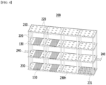
- Fig. 4 is a diagram showing a stacking section according to another embodiment of the present disclosure.
- the stacking section 200 may be formed with at least one hole 230h in each of the plates 230. More specifically, the at least one hole 230h may be formed on the plate 230 so as to have a predetermined interval or a predetermined pattern.
- the hole 230h in the plate 230 may be formed in consideration of the position where the electrode 110 is arranged. In one example, the hole 230h in the plate 230 may be formed in a portion in contact with the electrode 110. In other words, as shown in Fig. 4 , the electrode 110 may be located on a hole 230h formed in the plate 230.
- a surface in contact with the plate 230 among the outer surfaces of the electrode 110 can be in contact with the hole 230h, so that heat inside the chamber section 50 can be easily transferred to a surface of the outer surface of the electrode 110 in contact with the plate 230. That is, the drying performance of the electrode 110 due to the heat inside the chamber section 150 may be further improved even on the surface in contact with the plate 230 among the outer surface of the electrode 110.
- the plate 230 may be a heat conductive plate 231 made of a heat conductive material.
- the heat conductive plate 231 may be a sheet made of a heat conductive material.
- the heat conductive plate 231 may be a sheet made of a silicon (Si) material.
- the present disclosure is not limited thereto, and any material having excellent heat conductivity and durability may be included in the heat conductive plate 231 of the present embodiment.
- the heat conductive plate 231 may be coated with a heat conductive material on the plate 230.
- the surface in contact with the plate 230 among the outer surfaces of the electrode 110 can be dried even by heat conduction caused by the heat conductive material included in the heat conductive plate 231. That is, the drying performance of the electrode 110 with respect to a surface in contact with the heat conductive plate 231 among the outer surface of the electrode 110 can be further improved.
- the heat conductive plate 231 may be included by replacing the plate 230 depending on the position of the stacking section 200. In other words, depending on the position of the stacking section 200, there may be a position where the heat inside the chamber section 150 is transferred to be relatively low, and the plate 230 of the stacking section 200 that is at this position can be replaced with a heat conductive plate 231.
- the electrode drying device 1000 it is possible to reduce the variation in drying performance depending on the position of the stacking section 200.
- the plate 230 may further include at least one heating channel 240. More specifically, the heating channel 240 may be formed so as to extend from one side surface of the plate 230 toward the other side surface.
- the heating channel 240 may be connected to other components. In one example, the heating channel 240 may be connected to the first heater unit 160. In another example, the heating channel 240 may be connected to a heater unit separate from the first heater unit 160 and/or the second heater unit 170.
- the surface in contact with the plate 230 among the outer surfaces of the electrode 110 can be dried even by heat conduction caused by the heating channel 240 included in the plate 230. That is, the drying performance of the electrode 110 with respect to the surface in contact with the plate 230 among the outer surfaces of the electrode 110 can be further improved.
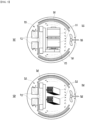
- Fig. 5 is a cross-sectional view of an electrode drying device according to a comparative example.
- Fig. 5(a) shows an electrode drying device 10 in which the electrode sheet 11 is in an electrode roll state according to Comparative Example 1.
- Fig. 5(b) shows an electrode drying device 20 in the case of a magazine type, which is an electrode stack 23 in which a plurality of electrodes are stacked according to Comparative Example 2.
- the electrode sheet 11 is dried in an electrode roll state, which causes a problem that moisture deviation occurs between the electrode sheet 11 portion located at the outer shell and the electrode sheet 11 portion located at the central portion.
- each electrode 110 is individually arranged on the stacking section 100, so that the moisture deviation between the electrodes 110 can be minimized, and thus the drying performance of the electrodes 110 can also be further improved.
Landscapes
- Engineering & Computer Science (AREA)
- Mechanical Engineering (AREA)
- General Engineering & Computer Science (AREA)
- Life Sciences & Earth Sciences (AREA)
- Chemical & Material Sciences (AREA)
- Microbiology (AREA)
- Manufacturing & Machinery (AREA)
- Chemical Kinetics & Catalysis (AREA)
- Electrochemistry (AREA)
- General Chemical & Material Sciences (AREA)
- Health & Medical Sciences (AREA)
- Molecular Biology (AREA)
- Combustion & Propulsion (AREA)
- Drying Of Solid Materials (AREA)
- Battery Electrode And Active Subsutance (AREA)
Abstract
Description
- This application claims the benefit of
Korean Patent Application No. 10-2021-0041835 filed on March 31, 2021 Korean Patent Application No. 10-2022-0007660 filed on January 19, 2022 - The present disclosure relates to an electrode drying device, and more particularly, to an electrode drying device that dries electrodes in a battery manufacturing process, wherein the electrode drying device dries residual moisture inside the electrode.
- Along with the technology development and increased demand for mobile devices, demand for secondary batteries as energy sources has been increasing rapidly. In particular, a secondary battery has attracted considerable attention as an energy source for power-driven devices, such as an electric bicycle, an electric vehicle, and a hybrid electric vehicle, as well as an energy source for mobile devices, such as a mobile phone, a digital camera, a laptop computer and a wearable device.
- The secondary battery may be classified based on the shape of a battery case into a cylindrical battery having an electrode assembly mounted in a cylindrical metal can, a prismatic battery having an electrode assembly mounted in a prismatic metal can, and a pouch type battery having an electrode assembly mounted in a pouch-shaped case made of a laminated aluminum sheet.
- Further, the secondary battery can be formed by inserting an electrode assembly composed of a positive electrode, a negative electrode, and a separator into a case, and then sealing the case. The electrode assembly can be formed by interposing a separator between the positive electrode and the negative electrode, and winding them in a j elly-roll type many times or laminating them in a plurality of layers.
- On the other hand, the secondary battery performs a process of drying the electrode when manufacturing an electrode such as a positive electrode or a negative electrode. In particular, the electrode is subjected to a drying process in a vacuum state, but there is a problem in that moisture deviation in the electrode occurs depending on the shape and position of the electrode. Therefore, there is a need to develop an electrode drying device capable of minimizing the moisture deviation inside the electrode in a drying process.
- It is an object of the present disclosure to provide an electrode drying device that dries electrodes in a battery manufacturing process, wherein the electrode drying device dries residual moisture inside the electrode.
- The objects of the present disclosure are not limited to the aforementioned objects, and other objects which are not described herein should be clearly understood by those skilled in the art from the following detailed description and the accompanying drawings.
- According to one embodiment of the present disclosure, there is provided an electrode drying device comprising: a chamber section; a stacking section in which at least one electrode is arranged separately from each other; a first heater unit located adjacent to the stacking section; and a circulation unit for circulating heat inside the chamber section.
- The stacking section includes a pair of plates facing each other, and a support part located at a corner of the plate and extending in a direction perpendicular to one surface of the plate, wherein the pair of plates may be connected to each other by the support part.
- The stacking section includes a first stacking section and a second stacking section in which the electrodes different from each other are respectively arranged, and the first stacking section and the second stacking section may be arranged in a vertical direction or a horizontal direction.
- The first stacking section and the second stacking section are arranged in a vertical direction, and among the pair of plates included in the first stacking section, a plate adjacent to the second stacking section may be included in the second stacking section.
- The first stacking section and the second stacking section are arranged in a horizontal direction, and among the support part included in the first stacking section, the support part located at each corner of an end part adjacent to the second stacking section may be included in the second stacking section.
- At least one hole may be formed in each of the plates.
- The electrode may be located on the hole formed in the plate.
- The hole in the plate may be formed in a portion in contact with the electrode.
- The plate may be made of a heat conductive material.
- The plate may be a heat conductive sheet.
- The plate further may include at least one heating channel.
- The heating channel may be formed so as to extend from one side surface of the plate toward the other side surface.
- The heating channel may be connected with the first heater unit.
- The first heater unit may be located adjacent to the side surface of the stacking section, and the circulation unit may be located on the stacking section.
- The electrode drying device further includes comprises a second heater part located at the lower part of the stacking section, and the heater unit may be housed in the chamber section.
- According to embodiments, the electrode drying device of the present disclosure includes a stacking section in which at least one electrode is arranged separately from each other, thereby capable of improving drying performance for each electrode.
- The effects of the present disclosure are not limited to the effects mentioned above and additional other effects not described above will be clearly understood from the description of the appended claims by those skilled in the art.
-
-
Fig. 1 is a cross-sectional view of an electrode drying device according to an embodiment of the present disclosure; -
Fig. 2 is a diagram showing an electrode arranged in the electrode drying device ofFig. 1 ; -
Fig. 3 is a diagram showing a stacking section included in the electrode drying device ofFig. 1 ; -
Fig. 4 is a diagram showing a stacking section according to another embodiment of the present disclosure; and -
Fig. 5 is a cross-sectional view of an electrode drying device according to a comparative example. - Hereinafter, various embodiments of the present disclosure will be described in detail with reference to the accompanying drawings so that those skilled in the art can easily carry out them. The present disclosure may be carried out in various different forms other than those described below, and the scope of the present disclosure is not limited by the embodiments described herein.
- Portions that are irrelevant to the description will be omitted to clearly describe the present disclosure, and like reference numerals designate like elements throughout the description.
- Further, in the drawings, the size and thickness of each element are arbitrarily illustrated for convenience of explanation, and the present disclosure is not necessarily limited to those illustrated in the drawings. In the drawings, the thickness of layers, regions, etc. are exaggerated for clarity. In the drawings, for convenience of explanation, the thicknesses of some layers and regions are exaggerated.
- Further, throughout the specification, when a portion is referred to as "including" or "comprising" a certain component, it means that the portion can further include other components, without excluding the other components, unless otherwise stated.
- Further, throughout the specification, when referred to as "planar", it means when a target portion is viewed from the upper side, and when referred to as "cross-sectional", it means when a target portion is viewed from the side of a cross section cut vertically.
-
Fig. 1 is a cross-sectional view of an electrode drying device according to an embodiment of the present disclosure.Fig. 2 is a diagram showing an electrode arranged in the electrode drying device ofFig. 1 . - Referring to
Fig. 1 , theelectrode drying device 1000 according to an embodiment of the present disclosure includes achamber section 150; astacking section 100 in which at least oneelectrode 110 is arranged separately from each other; afirst heater unit 160 located adjacent to thestacking section 100; and acirculation unit 180 that circulates heat inside thechamber section 150; and achamber section 150 in which thestacking section 100, thefirst heater unit 160 and thecirculation unit 180 are housed. - Here, the
chamber section 150 may be a space maintained in a vacuum state. The vacuum state mentioned herein may mean a state of an environment lower than the atmospheric pressure. Thereby, in theelectrode drying device 1000 according to the present embodiment, the drying process for theelectrode 110 is performed in thechamber section 150, so that the drying performance is excellent compared to that in the atmospheric pressure environment, and additionally, bubbles inside theelectrode 110 can also be removed. - In one an example, referring to
Figs. 1 and2 , theelectrode 110 can be manufactured by being cut or notched from theelectrode sheet 115 based on the cutting line A-A. Here, theelectrode 110 may correspond to a positive electrode or a negative electrode. That is, theelectrode sheet 115 may also correspond to a positive electrode sheet or a negative electrode sheet. However, the method of manufacturing theelectrode 110 is not limited thereto, and may include manufacturing in the form of an individual electrode rather than theelectrode sheet 115. - Further, the
electrodes 110 may be individually arranged on thestacking section 100 using a separate robot or a gripper. However, the device for stacking theelectrode 110 on thestacking section 100 is not limited thereto, and any device that can be easily arranged on thestacking section 100 without giving damage to theelectrode 110 is included in the present embodiment. - Further, the
first heater unit 160 can be located adjacent to thestacking section 100. In one example, thefirst heater unit 160 can be located adjacent to the side surface of thestacking section 100. More specifically, as shown inFig. 1 , thefirst heater unit 160 can be located in the form of surrounding the side surface of thestacking section 100. However, the position of thefirst heater unit 160 is not limited thereto, and any position capable of removing moisture from theelectrode 110 arranged on thestacking section 100 can be included in the present embodiment. - Further, the
first heater unit 160 may have a curved shape as shown inFig. 1 . More specifically, thefirst heater unit 160 is extended along the side surface of the stackingsection 100, but may be extended in a curved shape. However, the shape of thefirst heater unit 160 is not limited thereto, and any shape capable of removing moisture from theelectrode 110 arranged on the stackingsection 100 can be included in the present embodiment. - Further, the
electrode drying device 1000 according to the present embodiment may further include asecond heater unit 170. Here, thesecond heater unit 170 may be housed in thechamber section 150 together with other components. More specifically, as shown inFig. 1 , thesecond heater unit 170 may be located at the lower part of the stackingsection 100. - Here, the
first heater unit 160 and thesecond heater unit 170 mentioned herein may be heaters that can be generally used for drying theelectrode 110. In one example, each of thefirst heater unit 160 and thesecond heater unit 170 may be a far-infrared (FIR) heater, a mid-infrared (MIR) heater, or a near-infrared (NIR) heater. However, the present disclosure is not limited thereto, and any device capable of removing moisture from theelectrode 110 arranged on the stackingsection 100 can be included in the present embodiment. - Therefore, according to the above configuration, the
electrode drying device 1000 according to the present embodiment includes thefirst heater unit 160 and/or thesecond heater unit 170 surrounding the stackingsection 100, so that moisture inside theelectrode 110 arranged in the stackingsection 100 can be effectively removed. - Further, the
circulation unit 180 may circulate heat inside thechamber section 150. More specifically, as shown inFig. 1 , thecirculation unit 180 may be located on the stackingsection 100. In particular, heat inside thechamber section 150 can be generated by thefirst heater unit 160 and/or thesecond heater unit 170, and convection may occur in which heat inside thechamber section 150 transfers within thechamber section 150 by thecirculation unit 180. - In one example, the
circulation unit 180 may be a circulation fan (FAN). However, a device that can be used as thecirculation unit 180 is not limited thereto, and any device capable of circulating heat inside thechamber section 150 can be included in the present embodiment. - Thereby, according to the above configuration, the
electrode drying device 1000 of the present embodiment has a feature that heat inside thechamber section 150 is moved by thecirculation unit 180, and moisture in theelectrode 110 can be relatively uniformly removed regardless of the position of theelectrode 110 arranged on the stackingsection 100. -
Fig. 3 is a diagram showing a stacking section included in the electrode drying device ofFig. 1 . - Referring to
Figs. 1 and3 , the stackingsection 100 may include aplate 130 on which theelectrode 110 is arranged, and asupport part 120 that is located at the corner of theplate 130 and extends in a direction perpendicular to one surface of theplate 130. The stackingsection 100 may include a pair ofplates 130 facing each other, and the pair ofplates 130 may be connected to each other by thesupport part 120. Among the pair ofplates 130 included in the stackingsection 100, theplate 130 located at the relatively upper side may be referred to as an upper plate, and theplate 130 located at the lower side may be referred to as a lower plate. In this case, theelectrode 110 may be arranged on the lower plate. - More specifically, as shown in
Figs. 1 and3 , theplate 130 may have a size in which oneelectrode 110 can be arranged. In one example, theplate 130 may have a size equal to or larger than that of theelectrode 110. However, the size of theplate 130 is not limited thereto, and may have a size in which at least twoelectrodes 110 can be arranged. In this case, the at least twoelectrodes 110 may be arranged separately from each other on theplate 130. - Here, the
plate 130 may be made of a material such as steel. However, the present disclosure is not limited thereto, and any material having excellent durability can be included in theplate 130 of the present embodiment. - Further, the stacking
section 100 may include a first stacking section and a second stacking section in which theelectrodes 110 different from each other are respectively arranged. The first stacking section and the second stacking section can be arranged in a vertical direction or a horizontal direction. Here, the number of the first stacking section and the second stacking section included in the stackingsection 100 can be adjusted as needed. - The stacking
section 100 may include a first stacking section in which thefirst electrode 111 is arranged and a second stacking section in which thesecond electrodes first electrode 111 may be anyelectrode 110 arranged on the stackingsection 100, and thesecond electrodes electrodes 110 different fromfirst electrode 111. Thefirst electrode 111 and thesecond electrodes - More specifically, in the stacking
section 100, when the first stacking section and the second stacking section are arranged in a vertical direction, theplate 130 adjacent to the first stacking section among the pair ofplates 130 included in the second stacking section may be aplate 130 adjacent to the second stacking section among the pair ofplates 130 included in the first stacking section. In other words, as shown inFigs. 1 and3 , when the first stacking section and the second stacking section are arranged in a vertical direction, the first stacking section and the second stacking section may include oneplate 130 together. The first stacking section and the second stacking section may share oneplate 130. Among the pair ofplates 130 included in the first stacking section, aplate 130 adjacent to the second stacking section may be included in the second stacking section. - In other words, as illustrated in
Fig. 3 , the stackingsection 100 may include a first stacking section in which thefirst electrode 111 is arranged and a second stacking section in which thesecond electrode 113A is arranged. Thefirst electrode 111 and thesecond electrode 113A may be arranged in a vertical direction. Thefirst electrode 111 and thesecond electrode 113A may be arranged so as to face each other. One surface of thefirst electrode 111 and one surface of thesecond electrode 113A may be arranged so as to face each other. Thefirst electrode 111 may be arranged on the lower plate of the first stacking section, and thesecond electrode 113A may be arranged on a lower plate of the second stacking section. The first stacking section may be located on the upper side of the second stacking section, wherein the lower plate of the first stacking section may be an upper plate of the second stacking section. Here, unlike the one illustrated, the first stacking section may be located on the lower side of the second stacking section, wherein the upper plate of the first stacking section may be a lower plate of the second stacking section. - More specifically, in the stacking
section 100, when the first stacking section and the second stacking section are arranged in a horizontal direction, one end part of the pair ofplates 130 included in the first stacking section and one end part of the pair ofplates 130 included in the second stacking section may be in contact with each other. In one example, one end part of the pair ofplates 130 included in the first stacking section and one end part of the pair ofplates 130 included in the second stacking section can be fixed to each other by a fixing method such as weld-joining. In another example, one end part of the pair ofplates 130 included in the first stacking section and one end part of the pair ofplates 130 included in the second stacking section can be manufactured by being integrated with each other. - Additionally, both ends of the
support part 120 may be in contact with the corners of the pair ofplates 130 in a direction perpendicular to each other. In one example, both ends of thesupport part 120 may be fixed to the corners of the pair ofplates 130 by weld-joining or the like. In another example, a separate hole (not shown) is formed in the corners of the pair ofplates 130, and both ends of thesupport part 120 can be fixed by fitting in the hole. However, the fixing method between both ends of thesupport unit 120 and theplate 130 is not limited thereto, and other commonly used fixing methods are applicable. - Further, in the stacking
section 100, when the first stacking section and the second stacking section are arranged in a horizontal direction, thesupport part 120 adjacent to the second stacking section among thesupport parts 120 included in the first stacking section may be asupport part 120 adjacent to the first stacking section among thesupport parts 120 included in the second stacking section. In other words, as shown inFigs. 1 and3 , when the first stacking section and the second stacking section are arranged in a horizontal direction, the first stacking section and the second stacking section may include asupport part 120 located at each corner of an end part in contact with each other. The first stacking section and the second stacking section may share thesupport part 120 located at each corner of the end parts adjacent to each other. Among thesupport parts 120 included in the first stacking section, thesupport parts 120 located at each corner of an end adjacent to the second stacking section can be included in the second stacking section. - In other words, as illustrated in
Fig. 3 , the stackingsection 100 may include a first stacking section in which thefirst electrode 111 is arranged and a second stacking section in which thesecond electrode 113B is arranged. Thefirst electrode 111 and thesecond electrode 113B may be arranged in a horizontal direction. Thefirst electrode 111 and thesecond electrode 113B may be arranged side by side. Thefirst electrode 111 and thesecond electrode 113B may be arranged on the same plane. Thefirst electrode 111 may be arranged on the lower plate of the first stacking section, and thesecond electrode 113B may be arranged on a lower plate of the second stacking section. The lower plate of the first stacking section and the lower plate of the second stacking section may be arranged side by side. The lower plate of the first stacking section and the lower plate of the second stacking section may be arranged on the same plane. The first stacking section may be located on one side of the second stacking section, and one end part of the first stacking section and one end part of the second stacking section may be located adjacent to each other. At this time, thesupport part 120 located at each corner of the end adjacent to the second stacking section of thesupport part 120 of the first stacking section may be asupport part 120 located at each corner of an end portion adjacent to the first stacking section among thesupport unit 120 of the second stacking section. - Thereby, according to the above configuration, the
electrode drying device 1000 of the present embodiment has a feature that the pair ofplates 130 may be separated from each other by thesupport part 120, and theelectrodes 110 arranged on eachplate 130 may also be separated from each other by the length of thesupport part 120. That is, the upper surface of theelectrode 110 disposed on theplate 130 may be exposed in thechamber section 150, so that the drying performance of theelectrode 110 by heat inside thechamber section 150 can be improved. - Next, the stacking
section 200 according to another embodiment of the present disclosure will be described. However, in the following, the portions different from the stackingsection 100 which is the above-mentioned embodiment will be mainly described, and portions that can be described similarly to the stackingsection 100 which is the above-mentioned embodiment will be omitted. -
Fig. 4 is a diagram showing a stacking section according to another embodiment of the present disclosure. - Referring to
Fig. 4 , the stackingsection 200 may be formed with at least onehole 230h in each of theplates 230. More specifically, the at least onehole 230h may be formed on theplate 230 so as to have a predetermined interval or a predetermined pattern. - Further, the
hole 230h in theplate 230 may be formed in consideration of the position where theelectrode 110 is arranged. In one example, thehole 230h in theplate 230 may be formed in a portion in contact with theelectrode 110. In other words, as shown inFig. 4 , theelectrode 110 may be located on ahole 230h formed in theplate 230. - Thereby, in the
electrode drying device 1000 according to the present embodiment, a surface in contact with theplate 230 among the outer surfaces of theelectrode 110 can be in contact with thehole 230h, so that heat inside the chamber section 50 can be easily transferred to a surface of the outer surface of theelectrode 110 in contact with theplate 230. That is, the drying performance of theelectrode 110 due to the heat inside thechamber section 150 may be further improved even on the surface in contact with theplate 230 among the outer surface of theelectrode 110. - Further, according to another embodiment of the present disclosure, the
plate 230 may be a heatconductive plate 231 made of a heat conductive material. For example, the heatconductive plate 231 may be a sheet made of a heat conductive material. In this case, the heatconductive plate 231 may be a sheet made of a silicon (Si) material. However, the present disclosure is not limited thereto, and any material having excellent heat conductivity and durability may be included in the heatconductive plate 231 of the present embodiment. In another example, the heatconductive plate 231 may be coated with a heat conductive material on theplate 230. - Therefore, in the
electrode drying device 1000 according to the present embodiment, the surface in contact with theplate 230 among the outer surfaces of theelectrode 110 can be dried even by heat conduction caused by the heat conductive material included in the heatconductive plate 231. That is, the drying performance of theelectrode 110 with respect to a surface in contact with the heatconductive plate 231 among the outer surface of theelectrode 110 can be further improved. - Further, the heat
conductive plate 231 may be included by replacing theplate 230 depending on the position of the stackingsection 200. In other words, depending on the position of the stackingsection 200, there may be a position where the heat inside thechamber section 150 is transferred to be relatively low, and theplate 230 of the stackingsection 200 that is at this position can be replaced with a heatconductive plate 231. - Thereby, in the
electrode drying device 1000 according to the present embodiment, it is possible to reduce the variation in drying performance depending on the position of the stackingsection 200. - According to yet another embodiment of the present disclosure, the
plate 230 may further include at least oneheating channel 240. More specifically, theheating channel 240 may be formed so as to extend from one side surface of theplate 230 toward the other side surface. Theheating channel 240 may be connected to other components. In one example, theheating channel 240 may be connected to thefirst heater unit 160. In another example, theheating channel 240 may be connected to a heater unit separate from thefirst heater unit 160 and/or thesecond heater unit 170. - Thereby, in the
electrode drying device 1000 according to the present embodiment, the surface in contact with theplate 230 among the outer surfaces of theelectrode 110 can be dried even by heat conduction caused by theheating channel 240 included in theplate 230. That is, the drying performance of theelectrode 110 with respect to the surface in contact with theplate 230 among the outer surfaces of theelectrode 110 can be further improved. -
Fig. 5 is a cross-sectional view of an electrode drying device according to a comparative example. - Referring to
Fig. 5 , Fig. 5(a) shows anelectrode drying device 10 in which theelectrode sheet 11 is in an electrode roll state according to Comparative Example 1. Fig. 5(b) shows anelectrode drying device 20 in the case of a magazine type, which is anelectrode stack 23 in which a plurality of electrodes are stacked according to Comparative Example 2. - Referring to Fig. 5(a), in the
electrode drying device 10 according to Comparative Example 1, theelectrode sheet 11 is dried in an electrode roll state, which causes a problem that moisture deviation occurs between theelectrode sheet 11 portion located at the outer shell and theelectrode sheet 11 portion located at the central portion. - Referring to Fig. 5(b), in the
electrode drying device 20 according to Comparative Example 2, drying is performed on theelectrode stack 23 on which a plurality of electrodes are stacked, which causes a problem that moisture deviation occurs depending on the position (upper portion, central portion, or lower portion) of the electrode included in theelectrode stack 23. - In contrast, referring to
Figs. 1 to 4 , in theelectrode drying device 1000 according to the present embodiment, eachelectrode 110 is individually arranged on the stackingsection 100, so that the moisture deviation between theelectrodes 110 can be minimized, and thus the drying performance of theelectrodes 110 can also be further improved. - Although preferred embodiments of the present disclosure have been described in detail above, the scope of the present disclosure is not limited thereto, and various modifications and improvements made by those skilled in the art using the basic concepts of the present disclosure, which are defined in the appended claims, also belong to the scope of the present disclosure.
-
- 100, 200: stacking section
- 110: electrode
- 150: chamber section
- 160: first heater unit
- 170: second heater unit
- 180: circulation unit
- 1000: electrode drying device
Claims (15)
- An electrode drying device comprising:a chamber section;a stacking section in which at least one electrode is arranged separately from each other;a first heater unit located adjacent to the stacking section; anda circulation unit for circulating heat inside the chamber section.
- The electrode drying device of claim 1, wherein:the stacking section comprises a pair of plates facing each other, and a support part located at a corner of the plate and extending in a direction perpendicular to one surface of the plate,wherein the pair of plates are connected to each other by the support part.
- The electrode drying device of claim 2, wherein:the stacking section comprises a first stacking section and a second stacking section in which the electrodes different from each other are respectively arranged, andthe first stacking section and the second stacking section are arranged in a vertical direction or a horizontal direction.
- The electrode drying device of claim 3, wherein:the first stacking section and the second stacking section are arranged in a vertical direction, andamong the pair of plates included in the first stacking section, a plate adjacent to the second stacking section is included in the second stacking section.
- The electrode drying device of claim 3, wherein:the first stacking section and the second stacking section are arranged in a horizontal direction, andamong the support part included in the first stacking section, the support part located at each corner of an end part adjacent to the second stacking section is included in the second stacking section.
- The electrode drying device of claim 1, wherein:
at least one hole is formed in each of the plates. - The electrode drying device of claim 6, wherein:
the electrode is located on the hole formed in the plate. - The electrode drying device of claim 6, wherein:
the hole in the plate is formed in a portion in contact with the electrode. - The electrode drying device of claim 1, wherein:
the plate is made of a heat conductive material. - The electrode drying device of claim 9, wherein:
the plate is a heat conductive sheet. - The electrode drying device of claim 1, wherein:
the plate further comprises at least one heating channel. - The electrode drying device of claim 11, wherein:
the heating channel is formed so as to extend from one side surface of the plate toward the other side surface. - The electrode drying device of claim 12, wherein:
the heating channel is connected with the first heater unit. - The electrode drying device of claim 1, wherein:the first heater unit is located adjacent to the side surface of the stacking section, andthe circulation unit is located on the stacking section.
- The electrode drying device of claim 14, further comprising a second heater part located at the lower part of the stacking section.
Applications Claiming Priority (3)
| Application Number | Priority Date | Filing Date | Title |
|---|---|---|---|
| KR20210041835 | 2021-03-31 | ||
| KR1020220007660A KR102842440B1 (en) | 2021-03-31 | 2022-01-19 | Electrode drying device |
| PCT/KR2022/001187 WO2022211242A1 (en) | 2021-03-31 | 2022-01-24 | Electrode drying device |
Publications (2)
| Publication Number | Publication Date |
|---|---|
| EP4135064A1 true EP4135064A1 (en) | 2023-02-15 |
| EP4135064A4 EP4135064A4 (en) | 2023-11-22 |
Family
ID=83456444
Family Applications (1)
| Application Number | Title | Priority Date | Filing Date |
|---|---|---|---|
| EP22781363.1A Pending EP4135064A4 (en) | 2021-03-31 | 2022-01-24 | ELECTRODE DRYING DEVICE |
Country Status (4)
| Country | Link |
|---|---|
| US (1) | US20230304734A1 (en) |
| EP (1) | EP4135064A4 (en) |
| CN (1) | CN116391268A (en) |
| WO (1) | WO2022211242A1 (en) |
Cited By (1)
| Publication number | Priority date | Publication date | Assignee | Title |
|---|---|---|---|---|
| US20230304734A1 (en) * | 2021-03-31 | 2023-09-28 | Lg Energy Solution, Ltd. | Electrode Drying Device |
Families Citing this family (1)
| Publication number | Priority date | Publication date | Assignee | Title |
|---|---|---|---|---|
| CN116518670A (en) * | 2023-04-27 | 2023-08-01 | 安徽清氢能源科技有限公司 | Porous electrocatalytic electrode post-reaction drying device and control system thereof |
Family Cites Families (27)
| Publication number | Priority date | Publication date | Assignee | Title |
|---|---|---|---|---|
| US5651193A (en) * | 1994-02-09 | 1997-07-29 | The Gsi Group, Inc. | Grain dryer and control system therefor |
| CN101360965B (en) * | 2006-05-18 | 2010-12-22 | 富士胶片株式会社 | Method and apparatus for drying object to be dried |
| KR101077069B1 (en) * | 2011-02-28 | 2011-10-26 | (주)엠오텍 | Vacuum Drying Device and Drying Method of Anode Plate for Secondary Battery |
| CN202393179U (en) * | 2011-12-19 | 2012-08-22 | 甘国仁 | Lead battery pole-piece vacuum drying unit |
| US12281847B2 (en) * | 2020-04-21 | 2025-04-22 | Revive Electronics, LLC | Methods and apparatuses for drying electronic devices |
| US11713924B2 (en) * | 2012-02-01 | 2023-08-01 | Revive Electronics, LLC | Methods and apparatuses for drying electronic devices |
| CN203704556U (en) * | 2013-09-13 | 2014-07-09 | 凯迈(江苏)机电有限公司 | Vacuum drying oven for lithium batteries |
| US11384980B2 (en) * | 2013-10-17 | 2022-07-12 | Joseph P. Triglia, Jr. | System and method for reducing moisture in materials or plants using microwave radiation and RF energy |
| US10403880B2 (en) * | 2015-09-11 | 2019-09-03 | Iftikhar Ahmad | Apparatus and method for processing battery electrodes |
| KR101943507B1 (en) * | 2015-11-20 | 2019-01-29 | 주식회사 엘지화학 | Electrode drying apparatus and battery cell comprising electrode prepared thereby |
| US10199635B2 (en) * | 2016-09-22 | 2019-02-05 | Grst International Limited | Method of drying electrode assemblies |
| KR101800715B1 (en) * | 2016-12-09 | 2017-11-24 | 이인우 | Secondary battery plate drying method |
| CN206593395U (en) * | 2017-02-14 | 2017-10-27 | 江苏科耐尔新能源科技有限公司 | A kind of accumulator plate drying unit |
| CN108731392A (en) * | 2017-04-18 | 2018-11-02 | 江苏同科蓄电池股份有限公司 | A kind of pole plate drying system of accumulator |
| CN207180200U (en) * | 2017-08-28 | 2018-04-03 | 上海台姆超声设备有限公司 | A kind of lithium battery vacuum drying chamber |
| CA3113413A1 (en) * | 2017-10-13 | 2019-04-18 | Malcolm FREDRIC | Moisture measurement of timber |
| KR102312415B1 (en) * | 2018-09-13 | 2021-10-12 | 주식회사 엘지에너지솔루션 | Battery module, battery pack comprising the battery module and vehicle comprising the battery pack |
| WO2020106033A1 (en) * | 2018-11-19 | 2020-05-28 | 주식회사 엘지화학 | Method for manufacturing cylindrical battery and drying apparatus for performing same |
| CN209558796U (en) * | 2018-12-30 | 2019-10-29 | 武汉新能源研究院有限公司 | Minton dryer is used in a kind of production of vanadic anhydride cell positive material |
| CN210267939U (en) * | 2019-06-19 | 2020-04-07 | 东莞理工学院 | A pole plate drying device for lithium battery manufacturing |
| KR102748983B1 (en) * | 2019-07-03 | 2024-12-30 | 주식회사 엘지에너지솔루션 | Battery Module Including Flame Retardant Plate, Battery Rack and Power Storage Device Including the Same |
| CN210625152U (en) * | 2019-07-22 | 2020-05-26 | 江苏众凯电气科技有限公司 | Novel drying box |
| CN211823523U (en) * | 2019-12-12 | 2020-10-30 | 江西省世道新能源科技有限公司 | Lithium ion battery cell drying equipment |
| CN211012183U (en) * | 2019-12-13 | 2020-07-14 | 湖北锡宇汽车有限公司 | Welding rod drying device |
| JP7396207B2 (en) * | 2020-06-03 | 2023-12-12 | トヨタ自動車株式会社 | Electrode plate dryer |
| CN116391268A (en) * | 2021-03-31 | 2023-07-04 | 株式会社Lg新能源 | Electrode drying device |
| US12449197B1 (en) * | 2025-04-10 | 2025-10-21 | Windsor Engineering Group Limited | Timber drying kiln electrical contact system, a timber drying kiln moisture measurement system and a timber drying kiln moisture measurement method |
-
2022
- 2022-01-24 CN CN202280004064.1A patent/CN116391268A/en active Pending
- 2022-01-24 EP EP22781363.1A patent/EP4135064A4/en active Pending
- 2022-01-24 WO PCT/KR2022/001187 patent/WO2022211242A1/en not_active Ceased
- 2022-01-24 US US18/008,001 patent/US20230304734A1/en active Pending
Cited By (1)
| Publication number | Priority date | Publication date | Assignee | Title |
|---|---|---|---|---|
| US20230304734A1 (en) * | 2021-03-31 | 2023-09-28 | Lg Energy Solution, Ltd. | Electrode Drying Device |
Also Published As
| Publication number | Publication date |
|---|---|
| US20230304734A1 (en) | 2023-09-28 |
| WO2022211242A1 (en) | 2022-10-06 |
| CN116391268A (en) | 2023-07-04 |
| EP4135064A4 (en) | 2023-11-22 |
Similar Documents
| Publication | Publication Date | Title |
|---|---|---|
| US20240297362A1 (en) | Secondary Battery Module | |
| EP3340365B1 (en) | Battery module including array of cooling fins having different thicknesses | |
| CN111801810B (en) | Battery module including inner cover | |
| EP4135064A1 (en) | Electrode drying device | |
| CN113711433B (en) | Battery module and battery pack including the battery module | |
| EP4113647A1 (en) | Electrode drying device | |
| EP4024568B1 (en) | Battery pack and method of manufacturing the same | |
| US20160329532A1 (en) | Energy storage apparatus | |
| EP3067962B1 (en) | Battery pack | |
| EP3136466B1 (en) | Manufacture method of electrode assembly | |
| CN109314288B (en) | Air-cooled battery pack with improved assembly structure | |
| US20230299431A1 (en) | Battery cell, battery module, and battery pack including the same | |
| KR102842440B1 (en) | Electrode drying device | |
| US20170149032A1 (en) | Battery pack | |
| US12230839B2 (en) | Apparatus and method of manufacturing battery module | |
| EP4040575A1 (en) | Battery module and battery pack including same | |
| KR102561762B1 (en) | Secondary battery | |
| US12015134B2 (en) | Battery unit having cell stack, bus bars, cooler, waterproof plate, and heat transfer member | |
| WO2016043468A1 (en) | Battery cell including battery case having projecting portion formed thereon corresponding to step-structured electrode assembly | |
| EP4120441A1 (en) | Battery module and battery pack comprising same | |
| US20230275303A1 (en) | Rechargeable battery pack having a pouch cell, and method | |
| EP4579891A1 (en) | Secondary battery, manufacturing method for same secondary battery, and pressing device used for same manufacturing method | |
| EP4443580A1 (en) | Battery pack | |
| EP4398395A1 (en) | Battery pack and device including same | |
| EP4683231A1 (en) | Electronic device |
Legal Events
| Date | Code | Title | Description |
|---|---|---|---|
| STAA | Information on the status of an ep patent application or granted ep patent |
Free format text: STATUS: THE INTERNATIONAL PUBLICATION HAS BEEN MADE |
|
| PUAI | Public reference made under article 153(3) epc to a published international application that has entered the european phase |
Free format text: ORIGINAL CODE: 0009012 |
|
| STAA | Information on the status of an ep patent application or granted ep patent |
Free format text: STATUS: REQUEST FOR EXAMINATION WAS MADE |
|
| 17P | Request for examination filed |
Effective date: 20221109 |
|
| AK | Designated contracting states |
Kind code of ref document: A1 Designated state(s): AL AT BE BG CH CY CZ DE DK EE ES FI FR GB GR HR HU IE IS IT LI LT LU LV MC MK MT NL NO PL PT RO RS SE SI SK SM TR |
|
| A4 | Supplementary search report drawn up and despatched |
Effective date: 20231024 |
|
| RIC1 | Information provided on ipc code assigned before grant |
Ipc: F26B 21/02 20060101ALI20231018BHEP Ipc: F26B 9/06 20060101ALI20231018BHEP Ipc: F26B 5/04 20060101ALI20231018BHEP Ipc: F26B 3/30 20060101ALI20231018BHEP Ipc: F26B 25/18 20060101ALI20231018BHEP Ipc: F26B 25/06 20060101ALI20231018BHEP Ipc: F26B 3/02 20060101ALI20231018BHEP Ipc: H01M 4/04 20060101AFI20231018BHEP |
|
| DAV | Request for validation of the european patent (deleted) | ||
| DAX | Request for extension of the european patent (deleted) | ||
| STAA | Information on the status of an ep patent application or granted ep patent |
Free format text: STATUS: EXAMINATION IS IN PROGRESS |
|
| 17Q | First examination report despatched |
Effective date: 20250225 |