EP4134912A1 - Device and computer-implemented method for object tracking - Google Patents
Device and computer-implemented method for object tracking Download PDFInfo
- Publication number
- EP4134912A1 EP4134912A1 EP21190776.1A EP21190776A EP4134912A1 EP 4134912 A1 EP4134912 A1 EP 4134912A1 EP 21190776 A EP21190776 A EP 21190776A EP 4134912 A1 EP4134912 A1 EP 4134912A1
- Authority
- EP
- European Patent Office
- Prior art keywords
- embedding
- relational graph
- relation
- embeddings
- determining
- Prior art date
- Legal status (The legal status is an assumption and is not a legal conclusion. Google has not performed a legal analysis and makes no representation as to the accuracy of the status listed.)
- Granted
Links
Images



Classifications
-
- G—PHYSICS
- G06—COMPUTING OR CALCULATING; COUNTING
- G06T—IMAGE DATA PROCESSING OR GENERATION, IN GENERAL
- G06T7/00—Image analysis
- G06T7/20—Analysis of motion
-
- G—PHYSICS
- G06—COMPUTING OR CALCULATING; COUNTING
- G06T—IMAGE DATA PROCESSING OR GENERATION, IN GENERAL
- G06T7/00—Image analysis
- G06T7/20—Analysis of motion
- G06T7/246—Analysis of motion using feature-based methods, e.g. the tracking of corners or segments
-
- G—PHYSICS
- G06—COMPUTING OR CALCULATING; COUNTING
- G06V—IMAGE OR VIDEO RECOGNITION OR UNDERSTANDING
- G06V10/00—Arrangements for image or video recognition or understanding
- G06V10/70—Arrangements for image or video recognition or understanding using pattern recognition or machine learning
- G06V10/77—Processing image or video features in feature spaces; using data integration or data reduction, e.g. principal component analysis [PCA] or independent component analysis [ICA] or self-organising maps [SOM]; Blind source separation
- G06V10/774—Generating sets of training patterns; Bootstrap methods, e.g. bagging or boosting
-
- G—PHYSICS
- G06—COMPUTING OR CALCULATING; COUNTING
- G06V—IMAGE OR VIDEO RECOGNITION OR UNDERSTANDING
- G06V10/00—Arrangements for image or video recognition or understanding
- G06V10/70—Arrangements for image or video recognition or understanding using pattern recognition or machine learning
- G06V10/86—Arrangements for image or video recognition or understanding using pattern recognition or machine learning using syntactic or structural representations of the image or video pattern, e.g. symbolic string recognition; using graph matching
-
- G—PHYSICS
- G06—COMPUTING OR CALCULATING; COUNTING
- G06T—IMAGE DATA PROCESSING OR GENERATION, IN GENERAL
- G06T2207/00—Indexing scheme for image analysis or image enhancement
- G06T2207/10—Image acquisition modality
- G06T2207/10016—Video; Image sequence
-
- G—PHYSICS
- G06—COMPUTING OR CALCULATING; COUNTING
- G06T—IMAGE DATA PROCESSING OR GENERATION, IN GENERAL
- G06T2207/00—Indexing scheme for image analysis or image enhancement
- G06T2207/20—Special algorithmic details
- G06T2207/20072—Graph-based image processing
-
- G—PHYSICS
- G06—COMPUTING OR CALCULATING; COUNTING
- G06T—IMAGE DATA PROCESSING OR GENERATION, IN GENERAL
- G06T2207/00—Indexing scheme for image analysis or image enhancement
- G06T2207/20—Special algorithmic details
- G06T2207/20076—Probabilistic image processing
-
- G—PHYSICS
- G06—COMPUTING OR CALCULATING; COUNTING
- G06T—IMAGE DATA PROCESSING OR GENERATION, IN GENERAL
- G06T2207/00—Indexing scheme for image analysis or image enhancement
- G06T2207/20—Special algorithmic details
- G06T2207/20081—Training; Learning
-
- G—PHYSICS
- G06—COMPUTING OR CALCULATING; COUNTING
- G06T—IMAGE DATA PROCESSING OR GENERATION, IN GENERAL
- G06T2207/00—Indexing scheme for image analysis or image enhancement
- G06T2207/20—Special algorithmic details
- G06T2207/20084—Artificial neural networks [ANN]
-
- G—PHYSICS
- G06—COMPUTING OR CALCULATING; COUNTING
- G06T—IMAGE DATA PROCESSING OR GENERATION, IN GENERAL
- G06T2207/00—Indexing scheme for image analysis or image enhancement
- G06T2207/30—Subject of image; Context of image processing
- G06T2207/30232—Surveillance
-
- G—PHYSICS
- G06—COMPUTING OR CALCULATING; COUNTING
- G06T—IMAGE DATA PROCESSING OR GENERATION, IN GENERAL
- G06T2207/00—Indexing scheme for image analysis or image enhancement
- G06T2207/30—Subject of image; Context of image processing
- G06T2207/30241—Trajectory
-
- G—PHYSICS
- G06—COMPUTING OR CALCULATING; COUNTING
- G06T—IMAGE DATA PROCESSING OR GENERATION, IN GENERAL
- G06T2207/00—Indexing scheme for image analysis or image enhancement
- G06T2207/30—Subject of image; Context of image processing
- G06T2207/30248—Vehicle exterior or interior
- G06T2207/30252—Vehicle exterior; Vicinity of vehicle
Definitions
- the first model 302 is configured to determine further encodings of an interaction between the embedding 304-1 of the first object and the further embeddings of further objects including an N-th encoding 304-1N of an interaction between the embedding 304-1 of the first object and the embedding 304-N of the N-th object.
- LeakyReLU is an activation function
- W a 1 , and W a 2 are learnable parameters
- N i denotes the set of N objects for that their object embedding is within the predetermined distance to the i-th object in the spatial dimension.
- Temporal edges of the graph are not considered in this example.
- the t-th digital image 202-t is selected from the series of digital images.
- a step 406 is executed.
- Determining the t-th relation embeddings 208 comprises a step 406-2 of determining the coefficients ⁇ ij t for the encodings of interactions.
- the coefficients ⁇ ij t are determined for the N objects that are within the predetermined distance to each other.
- a step 410 is executed.
- the method may comprise an optional step 412.
- trajectories 120 are extended for the objects with the predicted positions.
- the method may comprise an optional step 414.
- a control signal is determined based on the predicted positions or based on the trajectories 120.
- the predicted positions may relate to vehicles or pedestrians that are tracked for surveillance or autonomous driving.
- the control signal may change an operation of a technical system, e.g. a robot, a machine or a vehicle, e.g. to avoid moving towards a predicted position of an object or to avoid crossing a trajectory of an object, or to move the input sensor 116 to follow a tracked object.
- a technical system e.g. a robot, a machine or a vehicle
- step 400 continues with step 400 in the example, until the T relational graph embeddings 200-T, ..., 200-1 are processed.
- the method of training comprises optimizing the learnable parameters of the model 126.
- the method of training may comprise optimizing parameters of the tracker 112.
- the method of training is based on a training on a labeled dataset.
- predicted positions of object are determined with the model 126.
- the predicted positions are determined in the example according to the steps 400 to 410.
- a step 506 is executed.
- a step 508 is executed.
- a backpropagation is run to update the learnable parameters of the model 126.
- the parameters of the tracker 112 may be learned as well with the backpropagation.
Landscapes
- Engineering & Computer Science (AREA)
- Theoretical Computer Science (AREA)
- Multimedia (AREA)
- Computer Vision & Pattern Recognition (AREA)
- General Physics & Mathematics (AREA)
- Physics & Mathematics (AREA)
- Computing Systems (AREA)
- General Health & Medical Sciences (AREA)
- Medical Informatics (AREA)
- Software Systems (AREA)
- Evolutionary Computation (AREA)
- Databases & Information Systems (AREA)
- Health & Medical Sciences (AREA)
- Artificial Intelligence (AREA)
- Image Processing (AREA)
- Editing Of Facsimile Originals (AREA)
Abstract
Description
- The invention relates to a device and a computer-implemented method for object tracking, in particular tracking vehicles or pedestrians for surveillance or autonomous driving.
- Tracking-by-regression is a multi-object tracking approach, where an association of objects is performed by utilizing a regression head of an object detector. Philipp Bergmann, Tim Meinhardt, and Laura Leal-Taixe. Tracking without bells and whistles, available at https://arxiv.org/abs/1903.05625, discloses aspects of tracking-by-regression.
- The device and computer-implemented method according to the independent claims have the ability to take complex dynamics of multiple objects into account.
- The computer-implemented method for object tracking comprises providing a sequence of digital images, determining a sequence of relational graph embeddings, wherein a first relational graph embedding of the sequence comprises a first object embedding representing a first object in a first digital image of the sequence of digital images, wherein the first relational graph embedding comprises a first relation embedding of a relation for the first object embedding, wherein the first relation embedding relates the first object embedding to embeddings representing other objects of the first digital image in the first relational graph embedding and to embeddings in a second relational graph embedding of the sequence that represent objects of a second digital image of the sequence of digital images. Thus, a spatial-temporal relation is extracted from the digital images and stored in a relational graph embedding. The relational graph embedding provides a data basis for significantly improving a prediction of a position of objects.
- The method may comprise mapping the first relational graph embedding and a position of the first object in the second digital image with a regression model to an output indicative of a predicted position of the first object in the first digital image or a change of the position for a predicted position of the first object in the first digital image. The output may be the position of a tracked object, or the change of the position between two digital images that were captured at different time steps. Using the relational graph embedding improves the prediction of the position.
- The method may comprise providing a position of the first object in the second digital image, determining the predicted position of the first object in the first digital image depending on the position of the first object in the second digital image and the output indicative of the change of the position. Providing the position of the object in the second digital image improves the prediction of the position in the first digital image further.
- The method may comprise reading a first trajectory for the first object from the at least one memory, determining the predicted position of the first object depending on the first trajectory, determining a second trajectory depending on the predicted position of the first object. Thus, the second trajectory is a continuation of the first trajectory that is based on the improved prediction of the position.
- The method may comprise receiving the sequence of digital images, in particular from a sensor, determining a control signal for a technical system, in particular a robot, a machine, or a vehicle, depending on the predicted position or a trajectory comprising the predicted position. Thus, an autonomous behavior of the technical system is improved based on the improved prediction of the position of objects in the digital images.
- The method may comprise determining the first relation embedding wherein determining the first relation embedding comprises determining an embedding of a spatial relation for the first object embedding, wherein the spatial relation relates the first object embedding to a set of object embeddings representing other objects of the first digital image in the first relational graph embedding, and determining the first relation embedding depending on the spatial relation and depending on a second relation embedding that is assigned by the second relational graph embedding to an object embedding representing the first object in the second relational graph embedding.
- The method may comprise determining the second relation embedding depending on a third relation embedding that is assigned by a third relational graph embedding of the sequence of relational graph embeddings to an object embedding representing the first object in the third relational graph embedding. Thus, the first relation embedding is determined successively from two other relation embeddings. The first relation embedding comprises a history of relation embeddings that provides the basis to further improve the prediction of the position.
- The method may comprise determining the set of object embeddings, wherein determining the set of object embeddings comprises determining embeddings in the first relational graph embedding that are within a predetermined distance to the first object embedding. Thus, objects that are near with respect to the spatial dimension of the digital image and near with respect to a depth of the digital image are selected for determining the relation embedding. These are the objects that are most relevant. Less relevant objects, e.g. objects that are far with respect to the depth of the digital image, are ignored. This improves the prediction of the position further.
- The method may comprise selecting the first relational graph embedding and the second relational graph embedding so that the first relational graph embedding is next to the second relational graph embedding in an order of the relational graph embeddings in the sequence of the relational graph embeddings. Thus, the relational graph embedding comprises a history of two digital images that are consecutively taken. This bases the prediction of the position at a time step to a time step nearby.
- The method may comprise determining an encoding of an interaction between the first object embedding and a second object embedding representing another object in the first digital image depending on the first object embedding the second object embedding and a measure for a distance between the first object embedding and the second object embedding, determining a first coefficient depending on a weighted product of the first object embedding and the second object embedding, determining the first relation embedding depending on a sum of the encoding of the interaction between the first object embedding and the second object embedding and at least one encoding of an interaction of the first object embedding with a third object embedding representing a different object than the first object and the second object, wherein the second object embedding and the third object embedding are within a predetermined spatial distance of the first object embedding, wherein the encoding of the interaction between the first object embedding and the second object embedding is weighted with the first coefficient. This way, interactions are captured as basis of the prediction.
- The method may comprise determining at least a part of learnable parameters of a model based on a training on a labeled dataset, wherein the model is configured to determine the sequence of relational graph embeddings and to determine predicted positions depending on the sequence of digital images, wherein predicted positions of objects are determined with the model according to the method of one of the
claims 1 to 10, wherein a loss function between the predicted positions and a ground truth from the labeled dataset is determined, wherein a backpropagation is run to update the learnable parameters of the model. - The method may comprise determining at least a part of learnable parameters of the regression model in the backpropagation.
- The device for object tracking comprises at least one processor and at least one memory, wherein the at least one memory comprises computer-readable instructions that, when executed by the at least one processor, cause the device to perform steps in the method.
- A non-transitory storage medium comprises computer-readable instructions that, when executed by a computer, cause the computer to perform steps in the method.
- Further advantageous embodiments are derivable from the following description and the drawing. In the drawing:
- Fig. 1
- schematically depicts a device for object tracking,
- Fig. 2
- schematically depicts an architecture of a model for object tracking,
- Fig. 3
- schematically depicts a module of the model,
- Fig. 4
- schematically depicts steps in a method for object tracking,
- Fig. 5
- schematically depicts steps in a method for training the model.
-
Figure 1 schematically depicts adevice 100 for object tracking. Thedevice 100 comprises at least oneprocessor 102 and at least onememory 104. - The at least one
memory 104 is configured to store computer-readable instructions 106 that, when executed by the at least oneprocessor 102, cause thedevice 100 to execute steps in a method for object tracking. - The at least one
memory 104 is configured to store at least onedigital image 108. The at least onememory 104 is configured to store at least one relational graph embedding 110. - The
device 100 in the example comprises atracker 112 for tracking objects in digital images. Thedevice 100 may comprise apreprocessor 114 and aninput sensor 116. Theinput sensor 116 in the example may be a radar sensor, a lidar sensor, a camera. Theinput sensor 116 may be configured to scan anenvironment 118 of thedevice 100 to provide the sensor data 120. - The
preprocessor 114 may be configured to create avideo stream 122 from sensor data 120. Thepreprocessor 114 may be configured to determine the at least onedigital image 108 from thevideo stream 122 and store it in the at least onememory 104. Thetracker 112 may be configured to track objects in digital images of thevideo stream 122. - The
tracker 112 may be configured tostore trajectories 124, e.g. sequences of positions of bounding boxes for detected objects, in the at least onememory 104. Thetracker 112 may configured to readstored trajectories 124 from the at least onememory 104. - The
device 100 comprises amodel 126 for object tracking. Themodel 126 is configured to determine the at least one relational graph embedding 110. - The
model 126 is configuredexchange information 128 about positions of object with thetracker 112. -
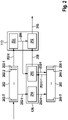
Figure 2 schematically depicts an architecture of themodel 126 for object tracking. - The
model 126 is configured to determine a sequence ofrelational graph embeddings 200 depending on a sequence ofdigital images 202. Themodel 126 may be configured to read the sequence ofdigital images 202 from the at least onememory 104. - The
tracker 112 may comprise anobject detector 204 that is configured for detecting objects in digital images. Theobject detector 204 may be configured to read the sequence ofdigital images 202 from the at least onememory 104. - The
object detector 204 may be configured to assign bounding boxes to objects that are detected by theobject detector 204. - The
object detector 204 is configured to determine aproposal 206 for a position of an object in a t-th digital image 202-t of the sequence ofdigital images 202. - The sequence of
digital images 202 comprises a plurality of T digital images 202-1, ..., 202-T. - The
model 126 is configured to determine a t-th relation embedding for the object in a t-th relational graph embedding 200-t that corresponds to the t-th digital image 202-t. Themodel 126 is configured to determine the t-th relation embedding depending on at least one relational embedding that is determined for another digital image. The other digital image in the example is the digital image that is next to the t-th digital image 202-t in a descending order of the sequence ofdigital images 202. Themodel 126 is configured to determine a t-th relation embedding 208 for the t-th relational graph embedding 200-t. In the example, themodel 126 is configured to determine a one-by-one mapping of digital images 202-1, ..., 202-T to relational graph embeddings 200-1, ..., 200-T. Themodel 126 is configured to determine consecutively a relational embedding of a relational graph embedding 200-t depending on the relational embedding that is determined for another relational graph embedding. In the example, the other relational graph embedding is the relational graph embedding that is determined for the other digital image. - The
object tracker 204 comprises anoutput 210 indicative of the position of the object in the t-th digital image 202-t or a change of the position of the object between the other digital image 202-t and the t-th digital image 202-t. - The
object tracker 204 is configured to map the t-th relation embedding 208 and theproposal 206 for the t-th digital image 202-t to anoutput 210. - The
object tracker 204 is configured to map the t-th relation embedding 208 and theproposal 206 with aregression model 212 to theoutput 210. - The
model 126 is configured to map the sequence ofdigital images 202 to the sequence ofrelational graph embeddings 200 with afunction 214 for building a spatial-temporal graph. Thefunction 214 maps the t-th digital image 202-t to the t-th relational embedding 200-t. - The
model 126 is configured to map the sequence of relational graph embeddings 200 to the t-th relation embedding 208 with arelation encoding module 216. - The
relation encoding module 216 is configured to receive theproposal 206 as information about the position from theobject detector 204 of thetracker 112. - The
relation encoding module 216 maps the other relational embedding and theproposal 206 for the t-th digital image 202-t to the t-th relational embedding 200-t. - A spatial-temporal graph is defined for example as:

relational graph embeddings 200, Vt reprensents vertices and Et represents edges of the graph at a time step t and Zt is a set of temporal edges from t to t + 1. - For object tracking, vertices correspond to tracked objects and temporal edges encode their trajectories. In the example, vertices, which correspond to the same object, are linked in time. In the example, vertices which of different objects are disconnected in time.
- To decide on spatial edges at the time step t, the
function 214 determines a distance matrix


- The distance matrix

- The first bounding box is an indication of a position of a first object in a digital image. The second bounding box is an indication of a position of a second object in this digital image. Other indications of the positions may be used as well, e.g. estimated object positions.
- The scaled Euclidean distance prevents linking vertices that represent objects that are close in the digital image regarding their center position but far away from each other with regard to the depth. An adjacency matrix A describing the relation between the vertices is obtained in the example by the
function 214 with a threshold d
-
Figure 3 schematically depicts therelation encoding module 216. - The
relation encoding module 216 comprises afirst model 302 that is configured to, at the time step t, map a set of N object embeddings
first model 302 and a set of N embeddings

first model 302. - The set of N embeddings

proposal 206 for the t-th digital image 202-t at the time step t. The set of N embeddings
- The set of N object embeddings

- The
first model 302 may comprise a neural network, e.g. a gated recurrent unit. - In the example, bounding box coordinates


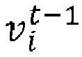


- A resulting relational graph embedding 304 comprises for a vertex ν 1 representing a first object an embedding 304-1 representing the vertex ν 1 and further embeddings 304-2, 304-3, 304-4, ..., 304-N representing N vertices ν 2 , ν 3 , ν 4, ..., νN that represent further objects, wherein N is a number of objects for that their object embedding is within a predetermined distance of the first object embedding 304-1.
- The
first model 302 is configured to determine in the relational graph embedding 304 a set of N embeddings
- A message between two objects that encodes their pairwise interaction is represented by a corresponding encoding in the relation graph embedding 304.
- The
first model 302 is configured to determine a first encoding 304-12 of an interaction between the embedding 304-1 of the first object and the embedding 304-2 of a second object. Thefirst model 302 is configured to determine a second encoding 304-13 of an interaction between the embedding 304-1 of the first object and the embedding 304-3 of a third object. Thefirst model 302 is configured to determine a first encoding 304-14 of an interaction between the embedding 304-1 of the first object and the embedding 304-4 of a fourth object. Thefirst model 302 is configured to determine further encodings of an interaction between the embedding 304-1 of the first object and the further embeddings of further objects including an N-th encoding 304-1N of an interaction between the embedding 304-1 of the first object and the embedding 304-N of the N-th object. - A message


1 , W m2 , b m1 , and b m2 are learnable parameters. - The messages of the objects are in the example aggregated in a respective coefficient:

1 , and W a2 are learnable parameters, wherein Ni denotes the set of N objects for that their object embedding is within the predetermined distance to the i-th object in the spatial dimension. Temporal edges of the graph are not considered in this example. - The
first model 302 is configured to an embedding

- The
relation encoding module 216 comprises asecond model 306 that is configured to, at the time step t, map the set of N embeddings
second model 306 and a relation embedding
second model 306 to a set of N relation embeddings
second model 306. - The
second model 306 may comprise neural network, e.g. a gated recurrent unit. - In the example, the set of N embeddings



- The initial hidden states of the second gated recurrent unit GRUrel may be set to zeros.
- In the example, the relational embeddings

- In the example, the temporal updates follow the spatial updates. The temporal update may be performed first followed by the spatial update.
- A relation importance


- In the example, the
tracker 112 is made aware of relations and conditions the predicted positions of objects on their relation embeddings. This allows thetracker 112 to jointly reason about groups of the objects and provides better identity preservation as an object can now be recognized based on how it relates to the neighbors. To do so, appearance features extracted from proposal regions are concatenated with the relation embeddings of the corresponding objects to combined features. The positional offset, i.e. the change of the position, is then predicted by passing the combined features via a regression head of a backbone object detector. The regression head in the example corresponds to theregression model 212. - The relation embeddings are calculated by the
relation encoding module 216 on top of trajectories that are produced by thetracker 112. - The
model 126 may comprise onerelation encoding module 216 for any object that is tracked by thetracker 112. - The relation features in the example are computed directly from the positions and do not rely on an appearance of the object. Thus, the relation embedding of an object can be used to estimate its position. For this, the relation embedding of an object of interest is input to e.g. a multilayer perceptron, MLP, which predicts the positional offset, i.e. the change of the position. The predicted offset may be used, e.g. added as offset, to the previous position of the object to predict the new position. The new position may be utilized for the next iteration of the relation encoding.
-
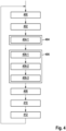
Figure 4 depicts a flow chart with steps of a method for object tracking. The method iterates through the sequence ofdigital images 202, in iteration t starting with the T-th digital image 202-T. T and threshold d are hyper-parameters, that are set. The sequence ofdigital images 202 of length T may be sampled from a longer sequence of digital images. - The method comprises a
step 400. - In the
step 400, the t-th digital image 202-t is selected from the series of digital images. - Afterwards, a
step 402 is executed. - In the
step 402 the positions
proposal 206. The positions of the objects may be determined by thetracker 112. Thetracker 112 may track objects that are detected by an object detector. - In the example, the positions


- Afterwards a
step 404 is executed. - In the step 404 a t-th relational graph embedding 200-t is determined.
- Determining the t-th relational graph embedding 200-t comprises a step 404-1 of determining embeddings of spatial relations for the N objects. In the example, the N embeddings of spatial relations are determined for the N objects that are within the predetermined distance to each other.
- Afterwards, a
step 406 is executed. - In the
step 406 the t-th relation embeddings 208 are determined. In the example, the N relation embeddings
- Determining the t-
th relation embeddings 208 comprises a step 406-1 of determining the encodings

- Determining the t-
th relation embeddings 208 comprises a step 406-2 of determining the coefficients

- Determining the t-
th relation embeddings 208 comprises a step 406-3 of determining the relation embeddings


- In the example, the t-
th relation embeddings 208 are determined for a pair of relational graph embeddings of the sequence ofrelational graph embeddings 200. The relational graph embeddings of the pair are selected in the example so that they are next to each other. The t-th relation embeddings are in the example determined based on the relation embeddings of the previous time step t - 1. - Afterwards a
step 408 is executed. - In the
step 408 the t-th relation embeddings 208 and theproposal 206 for the positions from thetracker 112 for the t-th first digital image 202-t are mapped with theregression model 212 to theoutput 210. - Afterwards, a
step 410 is executed. - In the
step 410 the predicted positions of the objects in the t-th digital image 202-t is determined depending on the position of the object in the digital image of the previous time step t - 1 and theoutput 210. - The method may comprise an
optional step 412. In theoptional step 412, trajectories 120 are extended for the objects with the predicted positions. - The method may comprise an optional step 414. In the
optional step 412, a control signal is determined based on the predicted positions or based on the trajectories 120. - The predicted positions may relate to vehicles or pedestrians that are tracked for surveillance or autonomous driving.
- The control signal may change an operation of a technical system, e.g. a robot, a machine or a vehicle, e.g. to avoid moving towards a predicted position of an object or to avoid crossing a trajectory of an object, or to move the
input sensor 116 to follow a tracked object. - Afterwards, the
step 400 is executed. - The method continues with
step 400 in the example, until the T relational graph embeddings 200-T, ..., 200-1 are processed. - Preferably, the digital images 202-T, ..., 202-1 and or the relational graph embeddings 200-T, ..., 200-1 are processed in the order in that the digital images 202-T, ..., 202-1 were taken. The method may comprise skipping digital images or relational graph embeddings or processing every n-th digital image or relational graph embedding, where n is an integer indicating the index in the order of the respective sequence.
- A method of training the
model 126 is described with reference tofigure 5 . - The method of training comprises optimizing the learnable parameters of the
model 126. The method of training may comprise optimizing parameters of thetracker 112. The method of training is based on a training on a labeled dataset. - The method comprises a
step 502. - In the
step 502, the sequence ofdigital images 202 is sampled. - Afterwards, a
step 504 is executed. - In the
step 504, predicted positions of object are determined with themodel 126. The predicted positions are determined in the example according to thesteps 400 to 410. - Afterwards, a
step 506 is executed. - In the
step 506, a loss function between the predicted positions and a ground truth from the labeled dataset is determined. - Afterwards, a
step 508 is executed. - In the
step 508, a backpropagation is run to update the learnable parameters of themodel 126. The parameters of thetracker 112 may be learned as well with the backpropagation.
Claims (14)
- Computer-implemented method for object tracking, characterized in that the method comprises providing (400) a sequence of digital images (202), determining (404) a sequence of relational graph embeddings (200), wherein a first relational graph embedding (200-i) of the sequence comprises a first object embedding (304-1) representing a first object in a first digital image (202-i) of the sequence of digital images (202), wherein the first relational graph embedding (200-i) comprises a first relation embedding of a relation for the first object embedding (304-1), wherein the first relation embedding relates the first object embedding (304-1) to embeddings (304-2, ..., 304-N) representing other objects of the first digital image in the first relational graph embedding (200-i) and to embeddings in a second relational graph embedding of the sequence that represent objects of a second digital image of the sequence of digital images (200).
- The method according to claim 1, characterized in that the method comprises mapping (408) the first relational graph embedding (200-i) and a position of the first object in the second digital image with a regression model (212) to an output (210) indicative of a predicted position of the first object in the first digital image (202-i) or a change of the position for a predicted position of the first object in the first digital image (202-i).
- The method according to claim 2, characterized in that the method comprises providing (402) the position of the first object in the second digital image, determining (410) the predicted position of the first object in the first digital image (202-i) depending on the position of the first object in the second digital image and the output (210) indicative of the change of the position.
- The method according to one of the claims 2 or 3, characterized by reading a first trajectory (120) for the first object from the at least one memory (106), determining the predicted position of the first object depending on the first trajectory (120), determining a second trajectory depending on the predicted position of the first object.
- The method according to one of the claims 2 to 4, characterized by receiving the sequence of digital images (202), in particular from a sensor, determining a control signal for a technical system, in particular a robot, a machine, or a vehicle, depending on the predicted position or a trajectory comprising the predicted position.
- The method according to one of the preceding claims, characterized in that the method comprises determining (404) the first relation embedding (200-1) wherein determining (404) the first relation embedding (200-i) comprises determining (404-1) an embedding (304-12, ..., 304-1N) of a spatial relation for the first object embedding (304-1), wherein the spatial relation (304-12, ..., 304-1N) relates the first object embedding (304-1) to a set of object embeddings (304-2, ..., 304-N) representing other objects of the first digital image (202-i) in the first relational graph embedding (200-i), and determining (404-5) the first relation embedding depending on the spatial relation (304-12, ..., 304-1N) and depending on a second relation embedding that is assigned by the second relational graph embedding to an object embedding representing the first object in the second relational graph embedding.
- The method according to claim 6, characterized in that the method comprises determining (406) the second relation embedding depending on a third relation embedding that is assigned by a third relational graph embedding of the sequence of relational graph embeddings (200) to an object embedding representing the first object in the third relational graph embedding.
- The method according to claim 6 or 7, characterized in that the method comprises determining (404-1) the set of object embeddings, wherein determining (404-1) the set of object embeddings comprises determining embeddings (304-2, ..., 304-N) in the first relational graph embedding (200-1) that are within a predetermined distance to the first object embedding (304-1).
- The method according to one of the preceding claims, characterized in that the method comprises selecting (406) the first relational graph embedding (200-i) and the second relational graph embedding so that the first relational graph embedding (200-i) is next to the second relational graph embedding in an order of the relational graph embeddings in the sequence of the relational graph embeddings (200).
- The method according to one of the preceding claims, characterized in that the method comprises determining (406-1) an encoding (304-12) of an interaction between the first object embedding (304-1) and a second object embedding (304-2) representing another object in the first digital image (202-1) depending on the first object embedding (304-1) the second object embedding (304-2) and a measure for a distance between the first object embedding (304-1) and the second object embedding (304-2), determining (406-2) a first coefficient depending on a weighted product of the first object embedding (304-1) and the second object embedding (304-2), determining (406-3) the first relation embedding depending on a sum of the encoding (304-12) of the interaction between the first object embedding (304-1) and the second object embedding (304-2) and at least one encoding (304-13) of an interaction of the first object embedding (304-1) with a third object embedding (304-3) representing a different object than the first object and the second object, wherein the second object embedding (304-2) and the third object embedding (304-3) are within a predetermined spatial distance of the first object embedding (304-1), wherein the encoding (304-12) of the interaction between the first object embedding (304-1) and the second object embedding (304-2) is weighted with the first coefficient.
- The method according to one of the preceding claims, characterized in that the method comprises determining at least a part of learnable parameters of a model (126) based on a training on a labeled dataset, wherein the model (126) is configured to determine the sequence of relational graph embeddings (200) and to determine predicted positions depending on the sequence of digital images (202), wherein predicted positions of objects are determined (504) with the model (126) according to the method of one of the claims 1 to 10, wherein a loss function between the predicted positions and a ground truth from the labeled dataset is determined (506), wherein a backpropagation is run (508) to update the learnable parameters of the model (126).
- The method according to claim 11, characterized in that the method comprises determining at least a part of learnable parameters of the regression model (212) in the backpropagation.
- Device (100) for object tracking, characterized in that the device (100) comprises at least one processor (102) and at least one memory (104), wherein the at least one memory (104) comprises computer-readable instructions (106) that, when executed by the at least one processor (102), cause the device (100) to perform steps in the method according to one of the claims 1 to 12.
- Non-transitory storage medium (104), characterized in that the medium comprises computer-readable instructions (106) that, when executed by a computer, cause the computer to perform steps in the method according to one of the claims 1 to 12.
Priority Applications (3)
| Application Number | Priority Date | Filing Date | Title |
|---|---|---|---|
| EP21190776.1A EP4134912B1 (en) | 2021-08-11 | 2021-08-11 | Device and computer-implemented method for object tracking |
| US17/873,131 US12573056B2 (en) | 2021-08-11 | 2022-07-25 | Device and computer-implemented method for object tracking |
| CN202210955450.0A CN115705653A (en) | 2021-08-11 | 2022-08-10 | Apparatus and computer-implemented method for object tracking |
Applications Claiming Priority (1)
| Application Number | Priority Date | Filing Date | Title |
|---|---|---|---|
| EP21190776.1A EP4134912B1 (en) | 2021-08-11 | 2021-08-11 | Device and computer-implemented method for object tracking |
Publications (2)
| Publication Number | Publication Date |
|---|---|
| EP4134912A1 true EP4134912A1 (en) | 2023-02-15 |
| EP4134912B1 EP4134912B1 (en) | 2025-10-08 |
Family
ID=77431126
Family Applications (1)
| Application Number | Title | Priority Date | Filing Date |
|---|---|---|---|
| EP21190776.1A Active EP4134912B1 (en) | 2021-08-11 | 2021-08-11 | Device and computer-implemented method for object tracking |
Country Status (3)
| Country | Link |
|---|---|
| US (1) | US12573056B2 (en) |
| EP (1) | EP4134912B1 (en) |
| CN (1) | CN115705653A (en) |
Families Citing this family (2)
| Publication number | Priority date | Publication date | Assignee | Title |
|---|---|---|---|---|
| US12586314B1 (en) * | 2023-07-31 | 2026-03-24 | Amazon Technologies, Inc. | Systems for generation of 3D models based on images of items |
| WO2025065724A1 (en) * | 2023-09-30 | 2025-04-03 | Nvidia Corporation | Decoupled queries for end-to-end 3d tracking using tranformer neural networks |
Citations (1)
| Publication number | Priority date | Publication date | Assignee | Title |
|---|---|---|---|---|
| US20210125344A1 (en) * | 2019-10-24 | 2021-04-29 | Microsoft Technology Licensing, Llc | Multiple object tracking |
Family Cites Families (1)
| Publication number | Priority date | Publication date | Assignee | Title |
|---|---|---|---|---|
| EP3705953B1 (en) * | 2019-03-06 | 2023-08-30 | Robert Bosch GmbH | Control of a physical system based on inferred state |
-
2021
- 2021-08-11 EP EP21190776.1A patent/EP4134912B1/en active Active
-
2022
- 2022-07-25 US US17/873,131 patent/US12573056B2/en active Active
- 2022-08-10 CN CN202210955450.0A patent/CN115705653A/en active Pending
Patent Citations (1)
| Publication number | Priority date | Publication date | Assignee | Title |
|---|---|---|---|---|
| US20210125344A1 (en) * | 2019-10-24 | 2021-04-29 | Microsoft Technology Licensing, Llc | Multiple object tracking |
Non-Patent Citations (4)
| Title |
|---|
| BERGMANN PHILIPP ET AL: "Tracking Without Bells and Whistles", 2019 IEEE/CVF INTERNATIONAL CONFERENCE ON COMPUTER VISION (ICCV), IEEE, 27 October 2019 (2019-10-27), pages 941 - 951, XP033723645, DOI: 10.1109/ICCV.2019.00103 * |
| MA CONG ET AL: "Deep Human-Interaction and Association by Graph-Based Learning for Multiple Object Tracking in the Wild", INTERNATIONAL JOURNAL OF COMPUTER VISION, KLUWER ACADEMIC PUBLISHERS, NORWELL, US, vol. 129, no. 6, 19 April 2021 (2021-04-19), pages 1993 - 2010, XP037462444, ISSN: 0920-5691, [retrieved on 20210419], DOI: 10.1007/S11263-021-01460-0 * |
| TANG SIYU ET AL: "Multi-person Tracking by Multicut and Deep Matching", 3 November 2016, COMPUTER VISION - ECCV 2020 : 16TH EUROPEAN CONFERENCE, GLASGOW, UK, AUGUST 23-28, 2020 : PROCEEDINGS; PART OF THE LECTURE NOTES IN COMPUTER SCIENCE ; ISSN 0302-9743; [LECTURE NOTES IN COMPUTER SCIENCE; LECT.NOTES COMPUTER], SPRINGER INTERNATIONAL PU, ISBN: 978-3-030-58594-5, XP047566084 * |
| WANG NAN ET AL: "An online multiple object tracker based on structure keeper net", APPLIED INTELLIGENCE, KLUWER ACADEMIC PUBLISHERS, DORDRECHT, NL, vol. 51, no. 11, 23 March 2021 (2021-03-23), pages 8010 - 8029, XP037582268, ISSN: 0924-669X, [retrieved on 20210323], DOI: 10.1007/S10489-021-02294-6 * |
Also Published As
| Publication number | Publication date |
|---|---|
| US12573056B2 (en) | 2026-03-10 |
| EP4134912B1 (en) | 2025-10-08 |
| CN115705653A (en) | 2023-02-17 |
| US20230051014A1 (en) | 2023-02-16 |
Similar Documents
| Publication | Publication Date | Title |
|---|---|---|
| Luo et al. | Fast and furious: Real time end-to-end 3d detection, tracking and motion forecasting with a single convolutional net | |
| Su et al. | Uncertainty quantification of collaborative detection for self-driving | |
| Pfeiffer et al. | A data-driven model for interaction-aware pedestrian motion prediction in object cluttered environments | |
| US11714423B2 (en) | Voxel based ground plane estimation and object segmentation | |
| Mersch et al. | Building volumetric beliefs for dynamic environments exploiting map-based moving object segmentation | |
| US7929730B2 (en) | Method and system for object detection and tracking | |
| CN114638855A (en) | Multi-target tracking method, equipment and medium | |
| Li et al. | Attentional-GCNN: Adaptive pedestrian trajectory prediction towards generic autonomous vehicle use cases | |
| CN110276783A (en) | A kind of multi-object tracking method, device and computer system | |
| Liu et al. | Yolo-3DMM for simultaneous multiple object detection and tracking in traffic scenarios | |
| EP4137997B1 (en) | Methods and system for goal-conditioned exploration for object goal navigation | |
| Aulia et al. | A new CNN-BASED object detection system for autonomous mobile robots based on real-world vehicle datasets | |
| US20240013409A1 (en) | Systems and Methods for Multi-Object Tracking | |
| Gao et al. | Efficient hierarchical reinforcement learning for mapless navigation with predictive neighbouring space scoring | |
| US20230051014A1 (en) | Device and computer-implemented method for object tracking | |
| Dey et al. | Robust perception architecture design for automotive cyber-physical systems | |
| Agrawal et al. | A systematic survey on recent deep learning-based approaches to multi-object tracking | |
| CN117557810A (en) | Research on an integrated detection and tracking algorithm based on attention mechanism and scale fusion | |
| Li et al. | Streammos: Streaming moving object segmentation with multi-view perception and dual-span memory | |
| Ronecker et al. | Dynamic occupancy grids for object detection: A radar-centric approach | |
| Dey et al. | Co-optimizing sensing and deep machine learning in automotive cyber-physical systems | |
| Bilro et al. | Pedestrian Trajectory Prediction Using LSTM and Sparse Motion Fields | |
| Parimi et al. | Dynamic speed estimation of moving objects from camera data | |
| Li et al. | Towards collision-free probabilistic pedestrian motion prediction for autonomous vehicles | |
| Dey et al. | Machine learning based perception architecture design for semi-autonomous vehicles |
Legal Events
| Date | Code | Title | Description |
|---|---|---|---|
| PUAI | Public reference made under article 153(3) epc to a published international application that has entered the european phase |
Free format text: ORIGINAL CODE: 0009012 |
|
| STAA | Information on the status of an ep patent application or granted ep patent |
Free format text: STATUS: THE APPLICATION HAS BEEN PUBLISHED |
|
| AK | Designated contracting states |
Kind code of ref document: A1 Designated state(s): AL AT BE BG CH CY CZ DE DK EE ES FI FR GB GR HR HU IE IS IT LI LT LU LV MC MK MT NL NO PL PT RO RS SE SI SK SM TR |
|
| STAA | Information on the status of an ep patent application or granted ep patent |
Free format text: STATUS: REQUEST FOR EXAMINATION WAS MADE |
|
| 17P | Request for examination filed |
Effective date: 20230816 |
|
| RBV | Designated contracting states (corrected) |
Designated state(s): AL AT BE BG CH CY CZ DE DK EE ES FI FR GB GR HR HU IE IS IT LI LT LU LV MC MK MT NL NO PL PT RO RS SE SI SK SM TR |
|
| GRAP | Despatch of communication of intention to grant a patent |
Free format text: ORIGINAL CODE: EPIDOSNIGR1 |
|
| RIC1 | Information provided on ipc code assigned before grant |
Ipc: G06T 7/20 20170101AFI20250305BHEP |
|
| STAA | Information on the status of an ep patent application or granted ep patent |
Free format text: STATUS: GRANT OF PATENT IS INTENDED |
|
| INTG | Intention to grant announced |
Effective date: 20250410 |
|
| GRAS | Grant fee paid |
Free format text: ORIGINAL CODE: EPIDOSNIGR3 |
|
| GRAA | (expected) grant |
Free format text: ORIGINAL CODE: 0009210 |
|
| STAA | Information on the status of an ep patent application or granted ep patent |
Free format text: STATUS: THE PATENT HAS BEEN GRANTED |
|
| AK | Designated contracting states |
Kind code of ref document: B1 Designated state(s): AL AT BE BG CH CY CZ DE DK EE ES FI FR GB GR HR HU IE IS IT LI LT LU LV MC MK MT NL NO PL PT RO RS SE SI SK SM TR |
|
| REG | Reference to a national code |
Ref country code: GB Ref legal event code: FG4D Ref country code: CH Ref legal event code: F10 Free format text: ST27 STATUS EVENT CODE: U-0-0-F10-F00 (AS PROVIDED BY THE NATIONAL OFFICE) Effective date: 20251008 |
|
| REG | Reference to a national code |
Ref country code: DE Ref legal event code: R096 Ref document number: 602021039950 Country of ref document: DE |
|
| REG | Reference to a national code |
Ref country code: IE Ref legal event code: FG4D |
|
| REG | Reference to a national code |
Ref country code: NL Ref legal event code: MP Effective date: 20251008 |
|
| REG | Reference to a national code |
Ref country code: AT Ref legal event code: MK05 Ref document number: 1845479 Country of ref document: AT Kind code of ref document: T Effective date: 20251008 |
|
| PG25 | Lapsed in a contracting state [announced via postgrant information from national office to epo] |
Ref country code: NL Free format text: LAPSE BECAUSE OF FAILURE TO SUBMIT A TRANSLATION OF THE DESCRIPTION OR TO PAY THE FEE WITHIN THE PRESCRIBED TIME-LIMIT Effective date: 20251008 |
|
| PG25 | Lapsed in a contracting state [announced via postgrant information from national office to epo] |
Ref country code: ES Free format text: LAPSE BECAUSE OF FAILURE TO SUBMIT A TRANSLATION OF THE DESCRIPTION OR TO PAY THE FEE WITHIN THE PRESCRIBED TIME-LIMIT Effective date: 20251008 |
|
| REG | Reference to a national code |
Ref country code: LT Ref legal event code: MG9D |
|
| PG25 | Lapsed in a contracting state [announced via postgrant information from national office to epo] |
Ref country code: NO Free format text: LAPSE BECAUSE OF FAILURE TO SUBMIT A TRANSLATION OF THE DESCRIPTION OR TO PAY THE FEE WITHIN THE PRESCRIBED TIME-LIMIT Effective date: 20260108 |
|
| PG25 | Lapsed in a contracting state [announced via postgrant information from national office to epo] |
Ref country code: HR Free format text: LAPSE BECAUSE OF FAILURE TO SUBMIT A TRANSLATION OF THE DESCRIPTION OR TO PAY THE FEE WITHIN THE PRESCRIBED TIME-LIMIT Effective date: 20251008 Ref country code: AT Free format text: LAPSE BECAUSE OF FAILURE TO SUBMIT A TRANSLATION OF THE DESCRIPTION OR TO PAY THE FEE WITHIN THE PRESCRIBED TIME-LIMIT Effective date: 20251008 Ref country code: FI Free format text: LAPSE BECAUSE OF FAILURE TO SUBMIT A TRANSLATION OF THE DESCRIPTION OR TO PAY THE FEE WITHIN THE PRESCRIBED TIME-LIMIT Effective date: 20251008 |
|
| PG25 | Lapsed in a contracting state [announced via postgrant information from national office to epo] |
Ref country code: RS Free format text: LAPSE BECAUSE OF FAILURE TO SUBMIT A TRANSLATION OF THE DESCRIPTION OR TO PAY THE FEE WITHIN THE PRESCRIBED TIME-LIMIT Effective date: 20260108 |
|
| PG25 | Lapsed in a contracting state [announced via postgrant information from national office to epo] |
Ref country code: IS Free format text: LAPSE BECAUSE OF FAILURE TO SUBMIT A TRANSLATION OF THE DESCRIPTION OR TO PAY THE FEE WITHIN THE PRESCRIBED TIME-LIMIT Effective date: 20260208 |
|
| PG25 | Lapsed in a contracting state [announced via postgrant information from national office to epo] |
Ref country code: PT Free format text: LAPSE BECAUSE OF FAILURE TO SUBMIT A TRANSLATION OF THE DESCRIPTION OR TO PAY THE FEE WITHIN THE PRESCRIBED TIME-LIMIT Effective date: 20260209 |
|
| PG25 | Lapsed in a contracting state [announced via postgrant information from national office to epo] |
Ref country code: PL Free format text: LAPSE BECAUSE OF FAILURE TO SUBMIT A TRANSLATION OF THE DESCRIPTION OR TO PAY THE FEE WITHIN THE PRESCRIBED TIME-LIMIT Effective date: 20251008 |
|
| PG25 | Lapsed in a contracting state [announced via postgrant information from national office to epo] |
Ref country code: LV Free format text: LAPSE BECAUSE OF FAILURE TO SUBMIT A TRANSLATION OF THE DESCRIPTION OR TO PAY THE FEE WITHIN THE PRESCRIBED TIME-LIMIT Effective date: 20251008 |