EP4134886A1 - Method for placement of device in treatment plant and method for manufacturing treatment plant - Google Patents
Method for placement of device in treatment plant and method for manufacturing treatment plant Download PDFInfo
- Publication number
- EP4134886A1 EP4134886A1 EP20930054.0A EP20930054A EP4134886A1 EP 4134886 A1 EP4134886 A1 EP 4134886A1 EP 20930054 A EP20930054 A EP 20930054A EP 4134886 A1 EP4134886 A1 EP 4134886A1
- Authority
- EP
- European Patent Office
- Prior art keywords
- pipe
- rack
- arrangement
- area
- sub
- Prior art date
- Legal status (The legal status is an assumption and is not a legal conclusion. Google has not performed a legal analysis and makes no representation as to the accuracy of the status listed.)
- Granted
Links
Images






Classifications
-
- G—PHYSICS
- G06—COMPUTING OR CALCULATING; COUNTING
- G06Q—INFORMATION AND COMMUNICATION TECHNOLOGY [ICT] SPECIALLY ADAPTED FOR ADMINISTRATIVE, COMMERCIAL, FINANCIAL, MANAGERIAL OR SUPERVISORY PURPOSES; SYSTEMS OR METHODS SPECIALLY ADAPTED FOR ADMINISTRATIVE, COMMERCIAL, FINANCIAL, MANAGERIAL OR SUPERVISORY PURPOSES, NOT OTHERWISE PROVIDED FOR
- G06Q10/00—Administration; Management
- G06Q10/06—Resources, workflows, human or project management; Enterprise or organisation planning; Enterprise or organisation modelling
- G06Q10/063—Operations research, analysis or management
- G06Q10/0631—Resource planning, allocation, distributing or scheduling for enterprises or organisations
- G06Q10/06315—Needs-based resource requirements planning or analysis
-
- G—PHYSICS
- G06—COMPUTING OR CALCULATING; COUNTING
- G06Q—INFORMATION AND COMMUNICATION TECHNOLOGY [ICT] SPECIALLY ADAPTED FOR ADMINISTRATIVE, COMMERCIAL, FINANCIAL, MANAGERIAL OR SUPERVISORY PURPOSES; SYSTEMS OR METHODS SPECIALLY ADAPTED FOR ADMINISTRATIVE, COMMERCIAL, FINANCIAL, MANAGERIAL OR SUPERVISORY PURPOSES, NOT OTHERWISE PROVIDED FOR
- G06Q10/00—Administration; Management
- G06Q10/04—Forecasting or optimisation specially adapted for administrative or management purposes, e.g. linear programming or "cutting stock problem"
-
- G—PHYSICS
- G06—COMPUTING OR CALCULATING; COUNTING
- G06F—ELECTRIC DIGITAL DATA PROCESSING
- G06F30/00—Computer-aided design [CAD]
- G06F30/10—Geometric CAD
- G06F30/18—Network design, e.g. design based on topological or interconnect aspects of utility systems, piping, heating ventilation air conditioning [HVAC] or cabling
-
- G—PHYSICS
- G06—COMPUTING OR CALCULATING; COUNTING
- G06F—ELECTRIC DIGITAL DATA PROCESSING
- G06F30/00—Computer-aided design [CAD]
- G06F30/20—Design optimisation, verification or simulation
- G06F30/25—Design optimisation, verification or simulation using particle-based methods
-
- G—PHYSICS
- G06—COMPUTING OR CALCULATING; COUNTING
- G06Q—INFORMATION AND COMMUNICATION TECHNOLOGY [ICT] SPECIALLY ADAPTED FOR ADMINISTRATIVE, COMMERCIAL, FINANCIAL, MANAGERIAL OR SUPERVISORY PURPOSES; SYSTEMS OR METHODS SPECIALLY ADAPTED FOR ADMINISTRATIVE, COMMERCIAL, FINANCIAL, MANAGERIAL OR SUPERVISORY PURPOSES, NOT OTHERWISE PROVIDED FOR
- G06Q50/00—Information and communication technology [ICT] specially adapted for implementation of business processes of specific business sectors, e.g. utilities or tourism
- G06Q50/04—Manufacturing
-
- G—PHYSICS
- G06—COMPUTING OR CALCULATING; COUNTING
- G06F—ELECTRIC DIGITAL DATA PROCESSING
- G06F2111/00—Details relating to CAD techniques
- G06F2111/06—Multi-objective optimisation, e.g. Pareto optimisation using simulated annealing [SA], ant colony algorithms or genetic algorithms [GA]
-
- G—PHYSICS
- G06—COMPUTING OR CALCULATING; COUNTING
- G06F—ELECTRIC DIGITAL DATA PROCESSING
- G06F2113/00—Details relating to the application field
- G06F2113/08—Fluids
-
- G—PHYSICS
- G06—COMPUTING OR CALCULATING; COUNTING
- G06F—ELECTRIC DIGITAL DATA PROCESSING
- G06F2113/00—Details relating to the application field
- G06F2113/14—Pipes
Definitions
- the present invention relates to a technology of determining an arrangement of devices included in a processing plant.
- Processing plants configured to process fluid include, for example, natural gas plants configured to liquefy natural gas or separate and recover natural gas liquid, petroleum refining plants configured to distill or desulfurize crude oil or various intermediates, and chemical plants configured to produce petrochemical products, intermediate chemicals, or polymers.
- the "fluid” includes, in addition to gas and liquid, granular materials (powder, grains, pellets, and the like) having flowability.
- Those processing plants each have a configuration in which a large number of devices are arranged in a predetermined installation area and those devices are connected to each other by pipes.
- Examples of the large number of devices include static devices such as columns, tanks, and heat exchangers, and dynamic devices such as pumps and compressors.
- Patent Literature 1 there is described a natural gas processing apparatus in which a range in which the devices are actually arranged is limited within a device arrangement area set in advance so as to correspond to a range of a working radius of a maintenance crane, which is determined in accordance with a lifting load.
- Patent Literature 1 there is no reference about the technology of quantitatively grasping the economic efficiency of the determined device arrangement.
- the present technology provides a technology of searching for an arrangement having a smaller total use amount of a pipe material for device groups each including devices included in a processing plant.
- a method of arranging devices of a processing plant configured to process fluid, the method including the steps of: dividing a plurality of devices included in the processing plant into a plurality of device groups which are distinguishable from one another, and each include at least one device and each have set therefor an occupied area including an arrangement area for the at least one device, and setting, for the plurality of device groups, connection information representing that, in order to transfer the fluid between each device included in one device group and a counterpart device included in another device group, two specific device groups are connected and paired via a pipe, and pipe information required for calculating a use amount of a pipe material per unit length of the pipe corresponding to the connection information; setting an installation area of the processing plant, and a pipe-rack arrangement area having a band-like planar shape of a pipe rack to be provided in the installation area to support the pipe; and repeatedly executing, by a computer, a first step and a second step while changing an arrangement of the plurality of device groups to obtain a plurality of device groups
- the method of arranging devices of a processing plant may include the following features.
- a method of manufacturing a processing plant configured to process fluid including a step of arranging a plurality of device groups based on an arrangement included in a plurality of arrangements having small total use amounts of pipe materials, which are selected by the method of arranging the devices of the processing plant described above, to thereby manufacture the processing plant.
- the computer obtains arrangements having small total use amounts of pipe materials.
- the economic efficiency of the determined device arrangement can be quantitatively grasped while the load of the work required for determining the device arrangement is reduced.
- FIG. 1 is a plan view for schematically illustrating a configuration of a processing plant 1 to which a method of arranging devices (device arrangement method) of this example is applied.
- processing plant 1 As the processing plant 1 to which the device arrangement method of this example is applicable, there can be exemplified, for example, the natural gas plants, the petroleum refining plants, and the chemical plants described above.
- Those processing plants 1 each include a large number of devices 31 configured to process fluid such as gas, liquid, or granular materials having flowability.
- the devices 31 to be provided in the processing plant 1 there can be exemplified static devices such as various processing columns, for example, a fractionator column and a reaction column, and receiver tanks and heat exchangers in which gas-liquid separation is performed.
- dynamic devices such as pumps and compressors.
- the devices 31 provided in the processing plant 1 are connected to each other via pipes 4 through which the fluid is allowed to flow.
- the processing plant 1 When the processing plant 1 is constructed in an installation area 10 set in advance, and the large number of devices 31 included in the installation area 10 are arranged in a disordered state, the pipes 4 for connecting the devices 31 to each other are increased in length, and a total use amount of a pipe material is increased. Further, also from the viewpoints of maintenance management and safety management, the devices 31 are desired to be arranged in order based on the way of thinking set in advance.
- the devices are divided into groups (hereinafter referred to as "device groups 3") in accordance with the order to process the fluid or relevance between the devices 31, and the devices 31 included in a common device group 3 may be collectively arranged in a unit area.
- the above-mentioned "unit area” is hereinafter referred to as "occupied area 30.”
- FIG. 1 shows a state in which the large number of devices 31 included in the processing plant 1 are divided into a plurality of device groups 3, and the devices 31 included in each device group 3 are arranged in the occupied area 30 set in association with the corresponding device group 3.
- the device group 3 includes at least one device 31.
- the grouping may be performed so that, along the flow of the fluid, one to dozens of devices 31 are included in one device group 3 for each type of treatment to which the fluid is subjected.
- the applicant is developing a method involving analyzing, by a computer, the relevance between the devices 31 based on data on a piping & instrument flow diagram created when the processing plant 1 is designed, and performing grouping so that the devices 31 having high relevance are included in the common device group 3.
- the devices 31 may be automatically divided into groups based on a predetermined algorithm.
- dynamic devices such as pumps and compressors, or packed columns having catalyst or adsorbents packed therein are provided redundantly in such a manner that a plurality of same devices are provided to allow switching and use at the time of maintenance, regeneration of the packing, and replacement, for example.
- Those redundant devices are often provided in the common device group 3.
- those devices 31 like a surge tank at an outlet of a compressor, there are also devices 31 designed on the premise that the devices 31 are provided at positions close to each other. In order to prevent the devices 31 of those types from being separated into different device groups 3 at the time of grouping, those devices 31 may be regarded as a set corresponding to one device 31, or those devices 31 may be set as one device group 3 in advance.
- the pipes 4 for connecting the devices 31 included in the common device group 3 to each other are arranged in the common occupied area 30 in which the device group 3 is arranged.
- the pipes 4 for connecting the devices 31 included in different device groups 3 to each other are arranged so as to pass through, in principle, pipe racks (main pipe rack 21, sub-pipe rack 22, and sub-sub-pipe rack 23) outside of the occupied area 30.
- the pipe racks 21, 22, and 23 are framework structures each configured to support the pipes 4 and formed into a band shape in plan view.
- an area having a band-like planar shape in which the pipe rack 21, 22, or 23 is to be arranged is referred to as "pipe-rack arrangement area 20.”
- the large number of devices 31 provided in the processing plant 1 are divided into a plurality of device groups 3, and the devices 31 included in each device group 3 are arranged in a common occupied area 30.
- devices 31 that are relevant to each other can be arranged at positions close to each other.
- excessive increase in length of the pipes 4 for connecting the devices 31 to each other can be suppressed, and the total use amount of the pipe material can be suppressed.
- a large number of device groups 3 may be obtained after the grouping, and those device groups 3 may be able to be arranged in the common installation area 10 in a large number of patterns.
- the length of the pipe 4 for connecting the devices 31 included in different device groups 3 to each other changes depending on arrangement positions of those device groups 3.
- pipes 4 having different diameters and thicknesses also vary in use amount of a pipe material.
- a pipe cost per unit weight varies as the selected pipe material is changed.
- the total use amount or a total cost of the pipe material which affects a construction cost of the processing plant 1, changes complicatedly depending on the pattern of the arrangement of the devices 31. Therefore, a considerable labor is required for the designer involved in the arrangement of the devices 31 in the processing plant 1 to search for an arrangement of the devices 31 having a smaller value in total use amount or total cost of the pipe material of the pipes 4 through trial and error. Further, the result may depend on the skill of the designer.
- the device arrangement method of this example uses a computer to search for an arrangement of the device groups 3 having a smaller total use amount (which may be converted into total cost, the same holds true in the following) of the pipes 4 to be arranged to pass through the pipe racks 21, 22, and 23.
- This problem can be understood as an optimization problem for searching for an arrangement having a smaller total use amount of the pipe material of the pipes 4 to be supported by the pipe racks 21, 22, and 23 when the plurality of device groups 3 are arranged in the installation area 10 of the processing plant 1.
- FIG. 2 is a plan view for schematically illustrating the installation area 10 of the processing plant 1 and the occupied areas 30 of the device groups 3 to be arranged in the installation area 10.
- the area installation area 10 is an area in which the occupied areas 30 and the pipe-rack arrangement areas 20 are arranged.
- the installation area 10 has coordinates set therein so that an area in which the occupied area 30 or the pipe-rack arrangement area 20 is arranged can be specified.
- FIG. 2 there is exemplified a case in which the installation area 10 has a rectangular outer edge, but the shape of the installation area 10 is not limited to this example.
- the shape of the installation area 10 may be set depending on a landform on which the processing plant 1 is constructed.
- the installation area 10 it is not essential to arrange, in the installation area 10, all of the devices 31 included in the processing plant 1 based on the device arrangement method of this example.
- devices having predetermined arrangement positions for example, devices for receiving raw materials from the outside, areas in which those devices are arranged may be excluded when the shape of the installation area 10 is set.
- the device arrangement area to be excluded from the installation area 10 may be set like an enclave inside the installation area 10.
- pipe-rack arrangement areas 20 are set for the installation area 10 in advance.
- the arrangement positions of the pipe racks 21, 22, and 23 and the number of pipe racks 21, 22, and 23 to be arranged can be changed when the arrangement of the device groups 3 is searched for. Details thereof are described later.
- the devices 31 of the processing plant 1 to be arranged in the installation area 10 are divided into a plurality of device groups 3 in advance.
- the device groups 3 are distinguishable from one another, and identification numbers of from "(1)" to "(25)" are assigned thereto in the example illustrated in FIG. 2 .
- an area and an outer-edge shape of the occupied area 30 are set in consideration of, for example, the number of devices 31 to be arranged, the size of each device 31, and an arrangement interval between the devices 31, which is set from the viewpoints of maintenance management and safety management.
- the outer-edge shape of the occupied 30 is also not limited to a rectangular shape exemplified in FIG. 2 (see also FIG. 4A and FIG. 4B ).
- the occupied 30 may have a connection side 301 set therein.
- the connection side 301 is to be connected to the pipe rack 21, 22, or 23.
- the area and the outer-edge shape of the occupied area 30 can be specified by determining a specific arrangement of devices 31 to be provided in the corresponding occupied are 30.
- a framework having a plurality of floors may be provided in the occupied area 30 so that the devices 31 are installed separately in those plurality of floors.
- determining the specific arrangement of the devices 31 is not an essential requirement to specify the area and the outer-edge shape of the occupied area 30.
- the area and the outer-edge shape of the occupied area 30 may be automatically calculated simply based on variables such as the number of devices 31 to be provided in the occupied area 30, the size of each device 31 (area of occupation), the arrangement interval between the devices 31, and presence or absence of the framework and the number of floors thereof.
- FIG. 3 is an illustration of a specific example in which the devices 31 included in a process of forming the processing plant 1 are divided into a plurality of device groups 3 (3a and 3b).
- FIG. 3 shows a process of cooling and liquifying, by an overhead cooler 312a, gas flowing out from a column top of a fractionator column 311a on a front-stage side, and feeding, by a liquid feed pump 314, part of liquid stored in a receiver 313a to a fractionator column 311b on a rear-stage side.
- a plurality of devices 31 relevant to the fractionator column 311a on the front-stage side are grouped as the device group 3a, and a plurality of devices 31 relevant to the fractionator column 311b on the rear-stage side are grouped as the device group 3b.
- the liquid feed pump 314 being the device 31 included in the device group 3a and the fractionator column 311b being the device 31 included in the device group 3b are connected to each other via the pipe 4.
- the device group 3a and the device group 3b are regarded as being paired via the pipe 4.
- devices 31 included in the device groups 3a and 3b perform such fluid transfer that the fluid flows in from the outside of each of the device groups 3a and 3b and the fluid flows out from each of the device groups 3a and 3b to the outside. Also this fluid transfer of those devices is regarded that each of the device groups 3a and 3b and another device group 3 are paired via the pipe 4 through which each type of fluid is allowed to flow.
- each device group 3 illustrated in FIG. 2 has set therefor information representing the devices 31 included in the corresponding device group 3. Further, for a corresponding one of those devices 31 configured to perform fluid transfer with a counterpart device 31 included in another device group 3 via the pipe 4, there is set connection information representing that those device groups 3 are paired. Even in a case in which fluid transfer is performed with the outside of the processing plant 1 or, as described above, the device arrangement region that is excluded in advance from the installation area 10, connection information representing this fact is set.
- connection information there is set information that allows identification of via which pipe 4 a specific device 31 (in the example of FIG. 3 , the liquid feed pump 314) included in one device group 3 (in the same example, the device group 3a) feeds fluid to a device 31 (in the same example, the fractionator column 311b) included in another device group 3 (in the same example, the device group 3b).
- connection information information representing via which pipe 4 the fluid is fed to a specific device 31 (in the same example, the fractionator column 311b) thereof from a device 31 (in the same example, the liquid feed pump 314) included in another device group 3 (in the same example, the device group 3a).
- any one device group 3 includes a plurality of devices 31 connected to devices 31 included in other device groups 3 via pipes 4, a plurality of pieces of the above-mentioned connection information are set so as to correspond to those devices 31.
- connection information may be set supposing that the one device 31 is connected to each of the other devices 31 via a plurality of pipes 4 different from each other.
- information corresponding to a use amount of a pipe material per unit length is set as pipe information in accordance with the diameter and the thickness of the corresponding pipe 4. Further, when the total cost is calculated as the total use amount of the pipe 4, pipe materials are further taken into consideration to set the cost per unit length of the pipe 4 as the pipe information. Those pieces of pipe information are not required to directly indicate the actual use amount (weight) or price of the pipe material per unit length, and may be, for example, identification information set in association with those values.
- next occupied area 30 cannot be arranged with an overlap in areas in which the pipe-rack arrangement areas 20 are arranged in advance or areas in which other occupied areas 30 are arranged in advance.
- each occupied area 30 is arranged in the installation area 10 so that the corresponding connection side 301 is brought into contact with a long side of the pipe-rack arrangement area 20.
- each occupied area 30 is arranged in the installation area 10 so that any side thereof that can have an interface for the pipe 4 with the pipe rack 21, 22, or 23 (which is generally a straight line but may be a curved line) is brought into contact with the long side of the pipe-rack arrangement area 20.
- the occupied area 30 can be arranged so that the side thereof corresponding to the interface for the pipe 4 (for example, the connection side 301) is brought into contact with the long side of the pipe-rack arrangement area 20, a part of the occupied area 30 may be allowed to protrude from the installation area 10 (occupied area 30 of (3) of FIG. 4B ). Conversely, a restriction that it is essential to include all of the occupied areas 30 in the installation area 10 may be provided.
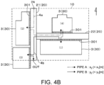
- FIG. 4A and FIG. 4B show examples in which four occupied areas 30 of "(1)” to “(4)" are arranged in the installation area 10 in which the pipe-rack arrangement areas 20 for the pipe racks 21 and 22 are arranged at predetermined positions.
- the fluid to be processed flows from a position indicated by reference symbol "IN” of FIG. 4A and FIG. 4B in order of the device groups 3 of "(2) ⁇ (4) ⁇ (1) ⁇ (3)," and flows to the outside through a position indicated by reference symbol “OUT” of FIG. 4A and FIG. 4B .
- positions in “IN ⁇ (2) ⁇ (4)” are connected by pipes A having common pipe information set therefor (in FIG. 4A and FIG. 4B , indicated by the arrow of the long dashed short dashed line and denoted by reference symbol "4a") .
- each of the pipes 4a and 4b a path of the pipe 4 that connects between interface positions of each device group 3 (or a position of "IN” or "OUT," the same holds true hereinafter in the description of FIG. 4A and FIG. 4B ) and the pipe rack 21 or 22 without meandering and turning back.
- the paths of the pipes 4a and 4b are illustrated in FIG. 4A and FIG. 4B so as to be shifted from each other without an overlap.
- interface positions of each device group 3 and the pipe rack 21 or 22 are further given here of the interface positions of each device group 3 and the pipe rack 21 or 22.
- interface positions close to the actual positions may be set in accordance with the arrangement.
- a specific arrangement of the devices 31 in the occupied area 30 has not been determined, for example, a simple setting of uniformly setting center positions of the connection sides 301 as the interface positions may be performed.
- FIG. 4A and FIG. 4B show examples of the latter case.
- the paths in which the pipes 4a and 4b are arranged are determined so as to correspond to the arrangement of the device groups 3, and the length of each of the pipes 4a and 4b can be calculated based on the coordinates of the paths. Then, the lengths of the pipes 4a and 4b for connecting the device groups 3 to each other are added for each type of pipe, and thus the total length of each of the pipes A and B can be calculated.
- the device groups 3 are arranged so that the pipes 4a and 4b are required to extend back and forth many times in the same area of the pipe-rack arrangement area 20 while the fluid flowing in from the position of IN flows out through the position of OUT.
- total lengths x 1 and y 1 of the respective pipes 4a and 4b tend to be increased.
- the use amount or the cost of the pipe material per unit length is multiplied based on the pipe information set for each of the pipes A and B. In this manner, the total use amount or the total cost of the pipe material of the pipes 4a and 4b can be calculated in accordance with the difference in arrangement of the device groups 3.
- the device arrangement method of this example uses the computer to repeatedly perform the above-mentioned calculation while changing the arrangement positions of the device groups 3, to thereby search for the arrangement of the device groups 3 having a smaller total use amount or total cost of the pipes 4a and 4b.
- the number of device groups 3 to be arranged in the installation area 10 is limited to four, but in actuality, an optimum arrangement of a large number of device groups 3 as illustrated in FIG. 2 may be required to be searched for. Further, the arrangement of the device groups 3 also changes under the influence of the arrangement of the pipe racks 21, 22, and 23 (pipe-rack arrangement areas 20) .
- the optimum arrangement of the device groups 3 may be searched for with various restrictions described below being provided.
- Parts (a) to (c) of FIG. 5 show examples of cases in which the number of main pipe racks 21 or sub-pipe racks 22 to be arranged and connection relationships of those pipe racks 21 and 22 are set in advance.
- one main pipe rack 21 is provided along a short-side direction of the installation area 10 set to have a rectangular shape, so as to cross the inside of the installation area 10.
- the arrangement direction of the main pipe rack 21, the lengths of the long side and the short side of the band-shaped pipe-rack arrangement area 20, and the number of main pipe racks 21 to be arranged are not limited to those of the examples of FIG. 5 .
- the main pipe rack 21 may be provided along a long-side direction of the installation area 10 set to have a rectangular shape, or the length of the long side of the main pipe rack 21 may be interrupted in the middle of crossing the installation area 10. Further, a plurality of main pipe racks 21 may be arranged in the installation area 10.
- the sub-pipe rack 22 is a pipe rack in which a short side of the band-shaped pipe-rack arrangement area 20 is connected to a long side of the pipe-rack arrangement area 20 of the main pipe rack 21, and which extends in a direction of intersecting with the long side.
- Part (a) of FIG. 5 shows an example in which no sub-pipe rack 22 is provided.
- part (b) of FIG. 5 shows an example in which one sub-pipe rack 22 is provided to each of a west long side and an east long side of the main pipe rack 21.
- Part (c) of FIG. 5 shows an example in which two sub-pipe racks 22 are provided to the west long side of the main pipe rack 21 and one sub-pipe rack 22 is provided to the east long side thereof.
- the lengths of the long side and the short side of the pipe-rack arrangement area 20 of the sub-pipe rack 22 and the number of sub-pipe racks 22 to be arranged may also be changed for each case.
- part (a) of FIG. 6 is an illustration for re-posting the case 3 illustrated in part (c) of FIG. 5 .
- part (a) of FIG. 6 one side of an outline of the installation area 10 extending in a direction (east-west direction) of intersecting with the long side of the main pipe rack 21 is equally divided into five areas, and respective divided areas are denoted by reference symbols "W2, W1, C, E1, and E2.”
- the main pipe rack 21 (pipe-rack arrangement area 20) illustrated in part (a) of FIG. 6 is set to be movable in the direction of intersecting with the long side thereof within a range of the divided area denoted by reference symbol C.
- the pipe-rack arrangement area 20 of the sub-pipe rack 22 is set to be movable in a direction of intersecting with the long side of the sub-pipe rack 22.
- two sub-pipe racks 22 are connected to the long side of the main pipe rack 21.
- the movable range of each sub-pipe rack 22 is limited to a range in which the pipe-rack arrangement area 20 of one sub-pipe rack 22 and the pipe-rack arrangement area 20 of another sub-pipe rack 22 do not overlap each other.
- the movement of the position of each pipe-rack arrangement area 20 described above is executed by a computer when the optimum arrangement of the device groups 3 is searched for.
- parts (b) and (c) of FIG. 6 are different in that the pipe-rack arrangement area 20 of the main pipe rack 21 is arranged in a divided area denoted by reference symbol W1 or E1. Also in those sub-cases, the pipe-rack arrangement area 20 of the main pipe rack 21 is set to be movable in the direction of intersecting with the long side thereof within a range of the divided area denoted by reference symbol W1 or E1.
- the movable range of the pipe-rack arrangement area 20 of the sub-pipe rack 22 is set similarly to that of the example of part (a) of FIG. 6 .
- part (c) of FIG. 5 there are prepared in advance a plurality of sub-cases which are common in the number of main pipe racks 21 to be arranged, the direction of the long side on which the sub-pipe rack 22 is connected to the main pipe rack 21, and the number of sub-pipe racks 22 to be connected to each long side, but vary from one another in the arrangement position of the main pipe rack 21.
- case is not limited to the case of part (c) of FIG. 5 .
- cases illustrated in parts (a) and (b) of FIG. 5 and other cases there are prepared a plurality of sub-cases which are different in the arrangement position of the main pipe rack 21 in the above-mentioned divided area (W2, W1, E1, or E2) .
- the optimum arrangement of the device groups 3 is searched for through use of a computer for each of the plurality of cases and sub-cases described above. As described above, there are prepared in advance cases and sub-cases in which the number of main pipe racks 21 and sub-pipe racks 22 to be arranged, the connection relationships thereof, and the movable range of the pipe-rack arrangement area 20 are limited in advance. In this manner, the calculation amount can be reduced as compared to a case in which the searching for the optimum arrangement of the device groups 3 is started from a state in which those conditions are not defined at all.
- FIG. 7 is an illustration of an example in which the connection side 301 to be connected to the long side of the pipe rack 21, 22, or 23 (pipe-rack arrangement area 20) is set in advance with respect to the outer edge of the occupied area 30 of the device group 3.
- connection side 301 When the connection side 301 is not set in advance conversely, any side of the occupied area 30 may be connected to the long side of the pipe rack 21, 22, or 23. However, when the connection side 301 is set in advance, the calculation amount of the computer can be reduced when the optimum arrangement of the device groups 3 is searched for.
- FIG. 7 there is also illustrated an example in which a maintenance area 5 is provided in an area on the opposite side of the connection side 301 across the occupied area 30.
- the maintenance area 5 is an area to which the device 31 arranged in the device group 3 is carried out at the time of maintenance, and which has none of the occupied area 30 and the pipe-rack arrangement area 20 of another device group 3 provided therein.
- connection side 301 a side selected to be connected to the long side of the pipe rack 21, 22, or 23 (pipe-rack arrangement area 20) is set as the connection side.
- the above-mentioned maintenance area 5 may be provided in an area on the opposite side of this connection side across the occupied area 30. This point is similar to that of the example illustrated in FIG. 7 .
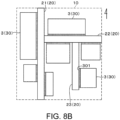
- the pipe-rack arrangement area 20 of the sub-sub-pipe rack 23 configured to be connected to a long side of the sub-pipe rack 22 and extend in a direction of intersecting with the long side may be generated, and the device group 3 may be connected to a long side of the generated sub-sub-pipe rack 23 ( FIG. 8B ). This operation is executed when the optimum arrangement of the device groups 3 is searched for.
- the arrangement positions of the occupied areas 30 of the plurality of device groups 3 and the arrangement positions of the pipe-rack arrangement areas 20 of the pipe racks 21, 22, and 23 are set as variable parameters.
- coordinate ranges to be occupied by the occupied areas 30 and the pipe-rack arrangement areas 20 are set as variable parameters.
- variable parameters are changed for each of the cases and sub-cases prepared in advance.
- the arrangement of the device groups 3 having a smaller total use amount or total cost of the pipes 4 is searched for.
- the searching for the arrangement of the device groups 3 satisfying such conditions can be executed by a computer through use of commercially-available and general-purpose optimization software.
- Examples of such software include modeFRONTIER of ESTECO, HyperStudy of Altair, Optimas of Noesis Solutions, and HEED of Red Cedar Technology.
- the optimum arrangement can be searched for through use of such optimization software or search tool by means of a genetic algorithm or a particle swarm optimization method.
- a genetic algorithm or a particle swarm optimization method As specific examples of the algorithm for executing those optimization methods, there can be exemplified Neighborhood Cultivation Genetic Algorithm (NCGA), Normal Boundary Intersection (NBI), and Indirect Optimization on the basis of Self-Organization (IOSO).
- NCGA Neighborhood Cultivation Genetic Algorithm
- NBI Normal Boundary Intersection
- IOSO Indirect Optimization on the basis of Self-Organization
- the searching for the optimum arrangement is not limited to the case of using those exemplified methods, and any method that can search for the arrangement of the device groups 3 having a small total use amount or total cost of the pipes 4 can be used.
- the computer which is configured to search for the optimum arrangement of the device groups 3 by means of the above-mentioned method, selects, from the found arrangements of the device groups 3, a plurality of arrangements having smaller total use amounts or total costs of the pipe materials of the pipes 4, and outputs the selected arrangements to a user.
- a preset number of arrangements may be output in the order of a smaller target value (total use amount or total cost) among the respective cases (including the sub-cases). Further, all arrangements having a target value smaller than a threshold value set in advance may be selected and output.
- FIG. 9 is an example of a procedure of executing the device arrangement method of this example.
- the plurality of devices 31 included in the processing plant 1 are divided into a plurality of device groups 3 in advance, and the area and the outer-edge shape of the occupied area 30 are determined in advance for each device group 3.
- connection information representing that two specific device groups 3 are paired via the pipe 4 and the pipe information for the corresponding pipe 4 are set based on the way of thinking described with reference to FIG. 3 (processing P1 of FIG. 9 ).
- the plurality of device groups 3 are arranged in the installation area 10 with the arrangement positions of the occupied areas 30 and the pipe-rack arrangement areas 20 being set as variable parameters (processing P3 of FIG. 9 : first step).
- the arrangement positions of the pipe-rack arrangement areas 20 may be changed within a range of the restriction described with reference to FIG. 6 . Further, the pipe-rack arrangement area 20 of the sub-sub-pipe rack 23 may be generated based on the way of thinking described with reference to FIG. 8A and FIG. 8B .
- the total use amount or the total cost (target value) of the pipe material of the pipes 4 is calculated based on the above-mentioned connection information and pipe information (processing P4 of FIG. 9 : second step).
- the first and second steps are repeated until an end condition set in advance (for example, a case in which, during a predetermined repetitive calculation period, an arrangement of the device groups 3 having a target value smaller than those of other arrangements cannot be found any more) is satisfied.
- the searching for the optimum arrangement may be ended at this time point, and information on this fact may be output.
- the user selects a more realistic arrangement of the device groups 3 in consideration of restrictions such as maintenance management and safety management, and cost factors other than the total use amount or the total cost of the pipe material.
- the arrangement of the device groups 3 is adjusted in light of also the various restrictions described above. As a result, as illustrated in FIG. 10 , the arrangement of the plurality of device groups 3 with respect to the installation area 10 illustrated in FIG. 2 is determined.
- the arrangement of the devices 31 included in the processing plant 1 is determined based on the arrangement of the device groups 3 determined as described above, and the processing plant 1 is constructed based on this arrangement.
- the computer obtains arrangements having small total use amounts or total cost of pipe materials. As a result, while the load of the work required for determining the device arrangement is reduced, the economic efficiency of the determined device arrangement can be quantitatively grasped.
- the arrangement positions of the pipe-rack arrangement areas 20 of the various pipe racks 21, 22, and 23 may be searched for through use of the computer.
- an initial arrangement of the device groups 3 (occupied areas 30) and the various pipe racks 21 and 22 (pipe-rack arrangement areas 20) may be set, and the computer may search for an arrangement of the device groups 3 having a total use amount or the like of the pipe material smaller than that of the initial arrangement.
- each pipe-rack arrangement area 20 it is not essential to set each pipe-rack arrangement area 20 to be movable in each of the cases and sub-cases described with reference to FIG. 6 .
- the optimum arrangement of the device groups 3 in each of the cases may be searched for under a condition in which the position of the pipe-rack arrangement area 20 is fixed. After that, the optimum arrangement of the device groups 3 may be searched for again under a condition in which the pipe-rack arrangement area 20 is movable in a specific case or sub-case having a smaller total use amount or the like of the pipe material.
- the processing plant 1 when the processing plant 1 is constructed, it is not essential to arrange all of the pipes that have been arranged in the pipe racks 21, 22, and 23 when the optimum arrangement is searched for even in the pipe racks 21, 22, and 23 in the actual processing plant 1.
- the pipe may connect those devices 31 without passing through the pipe rack 21, 22, or 23. It may be possible to further reduce the length of the pipe 4 as compared to a case in which the pipe 4 is routed from the arrangement position of each device 31 to the pipe rack 21, 22, or 23.
Landscapes
- Engineering & Computer Science (AREA)
- Business, Economics & Management (AREA)
- Physics & Mathematics (AREA)
- Theoretical Computer Science (AREA)
- Human Resources & Organizations (AREA)
- General Physics & Mathematics (AREA)
- Strategic Management (AREA)
- Economics (AREA)
- Geometry (AREA)
- General Business, Economics & Management (AREA)
- Tourism & Hospitality (AREA)
- Marketing (AREA)
- Entrepreneurship & Innovation (AREA)
- Computer Hardware Design (AREA)
- Evolutionary Computation (AREA)
- General Engineering & Computer Science (AREA)
- Game Theory and Decision Science (AREA)
- Development Economics (AREA)
- Operations Research (AREA)
- Quality & Reliability (AREA)
- Computational Mathematics (AREA)
- Primary Health Care (AREA)
- General Health & Medical Sciences (AREA)
- Health & Medical Sciences (AREA)
- Manufacturing & Machinery (AREA)
- Computer Networks & Wireless Communication (AREA)
- Mathematical Analysis (AREA)
- Mathematical Optimization (AREA)
- Pure & Applied Mathematics (AREA)
- Educational Administration (AREA)
- Pipeline Systems (AREA)
- Warehouses Or Storage Devices (AREA)
Abstract
Description
- The present invention relates to a technology of determining an arrangement of devices included in a processing plant.
- Processing plants configured to process fluid include, for example, natural gas plants configured to liquefy natural gas or separate and recover natural gas liquid, petroleum refining plants configured to distill or desulfurize crude oil or various intermediates, and chemical plants configured to produce petrochemical products, intermediate chemicals, or polymers. In this application, the "fluid" includes, in addition to gas and liquid, granular materials (powder, grains, pellets, and the like) having flowability.
- Those processing plants each have a configuration in which a large number of devices are arranged in a predetermined installation area and those devices are connected to each other by pipes. Examples of the large number of devices include static devices such as columns, tanks, and heat exchangers, and dynamic devices such as pumps and compressors.
- At this time, designers have been required to determine the arrangement of the large number of devices included in the processing plant through trial and error with comprehensive consideration of, for example, the order to process the fluid, restrictions on a landform and area of the installation area, restrictions in terms of safety, and use amounts of materials for forming the devices and pipes (economic efficiency).
- However, a processing plant in which a large number of devices are connected to each other via pipes often has a complicated configuration. At this time, not only work of searching for a more efficient device arrangement within a range of a large number of restrictions tends to require a large load for investigation, but also a result of the work may depend on the skill of the designer. Therefore, there has been a demand for a method with which, while the load of the work required for determining the device arrangement is reduced, the economic efficiency of the determined device arrangement can be quantitatively grasped.
- In
Patent Literature 1, there is described a natural gas processing apparatus in which a range in which the devices are actually arranged is limited within a device arrangement area set in advance so as to correspond to a range of a working radius of a maintenance crane, which is determined in accordance with a lifting load. InPatent Literature 1, however, there is no reference about the technology of quantitatively grasping the economic efficiency of the determined device arrangement. - [PTL 1]
WO 2018/235267 A1 - The present technology provides a technology of searching for an arrangement having a smaller total use amount of a pipe material for device groups each including devices included in a processing plant.
- According to one embodiment of the present invention, there is provided a method of arranging devices of a processing plant configured to process fluid, the method including the steps of: dividing a plurality of devices included in the processing plant into a plurality of device groups which are distinguishable from one another, and each include at least one device and each have set therefor an occupied area including an arrangement area for the at least one device, and setting, for the plurality of device groups, connection information representing that, in order to transfer the fluid between each device included in one device group and a counterpart device included in another device group, two specific device groups are connected and paired via a pipe, and pipe information required for calculating a use amount of a pipe material per unit length of the pipe corresponding to the connection information; setting an installation area of the processing plant, and a pipe-rack arrangement area having a band-like planar shape of a pipe rack to be provided in the installation area to support the pipe; and repeatedly executing, by a computer, a first step and a second step while changing an arrangement of the plurality of device groups to obtain a plurality of arrangements, and selecting a plurality of arrangements having small total use amounts of the pipe materials from the obtained plurality of arrangements, the first step including arranging the plurality of device groups in the installation area so that an outer edge of the occupied area of the one device group is brought into contact with a long side of the pipe-rack arrangement area having the band-like planar shape and so that the occupied area of the one device group and the occupied area of another device group are prevented from overlapping each other, the second step including calculating, for the arrangement of the plurality of device groups, the total use amount of the pipe material of the pipe to be supported by the pipe rack based on a position at which the outer edge of each occupied area is brought into contact with the long side and on the connection information.
- The method of arranging devices of a processing plant may include the following features.
- (a) The step of selecting the arrangements having the small total use amounts of the pipe materials includes executing a step of changing the arrangement of the plurality of device groups through use of a genetic algorithm or a particle swarm optimization method, to thereby select arrangements having smaller total use amounts of the pipe materials.
- (b) The step of setting the installation area and the pipe-rack arrangement area includes setting a plurality of cases which are different in at least one of an arrangement position of the pipe-rack arrangement area or the number of the pipe-rack arrangement area to be arranged, and the method further includes executing a step of selecting the arrangements having the small total use amounts of the pipe materials for each of the plurality of cases, and selecting, from selection results of the arrangements of the plurality of cases, a plurality of combinations of the cases and the arrangements having the smaller total use amounts of the pipe materials.
- (c) In Item (b), in the installation area, pipe-rack arrangement areas of a main pipe rack and a sub-pipe rack serving as the pipe rack are allowed to be set, the sub-pipe rack being configured to be connected to a long side of the main pipe rack and extend in a direction of intersecting with the long side, and the plurality of cases include cases in which the pipe-rack arrangement areas are set so as to vary in, as viewed from the main pipe rack, a direction of the long side thereof to which the sub-pipe rack is connected and the number of sub-pipe racks to be connected to each long side (including a case of zero).
- (d) In Item (c), the plurality of cases further include cases which are common in, as viewed from the main pipe rack, the direction of the long side thereof to which the sub-pipe rack is connected and the number of sub-pipe racks to be connected to each long side (including the case of zero), but vary from one another in an arrangement position of the main pipe rack in the direction of intersecting with the long side.
- (e) In Item (c), in the plurality of cases, the pipe-rack arrangement area of the main pipe rack is set to be movable within a range set in advance in the direction of intersecting with the long side, and the arrangement area of the sub-pipe rack is set to be movable in a direction of intersecting with a long side of the sub-pipe rack (which is limited to a range in which, when a plurality of sub-pipe racks are connected to the main pipe rack, an arrangement area of one sub-pipe rack and an arrangement area of another sub-pipe rack are prevented from overlapping each other), and when the first step is executed with the arrangement of the plurality of device groups being changed, arrangement positions of the pipe-rack arrangement areas of the main pipe rack and the sub-pipe rack are allowed to be changed.
- (f) In Item (c), when the first step is executed with the arrangement of the plurality of device groups being changed, a pipe-rack arrangement area of a sub-sub-pipe rack serving as the pipe rack is allowed to be generated, the sub-sub-pipe rack being configured to be connected to a long side of the sub-pipe rack and extending in a direction of intersecting with the long side of the sub-pipe rack.
- (g) In the plurality of device groups, a connection side to be connected to a long side of the pipe rack is set in advance with respect to the outer edge of each occupied area.
- (h) When the plurality of device groups are arranged in the step one, a maintenance area is provided in an area on an opposite side across the occupied region of a connection side to be connected to a long side of the pipe rack, the maintenance area being an area to which a device arranged in the one device group is carried out at a time of maintenance, and which has none of the occupied area and the pipe-rack arrangement area of another device group provided therein.
- (i) The pipe information includes information required for calculating a cost per unit length of the pipe as the use amount of the pipe material, and the second step includes calculating a total cost of the pipe material as the total use amount of the pipe material of the pipe to be supported by the pipe rack.
- Further, according to one embodiment of the present invention, there is provided a method of manufacturing a processing plant configured to process fluid, the method including a step of arranging a plurality of device groups based on an arrangement included in a plurality of arrangements having small total use amounts of pipe materials, which are selected by the method of arranging the devices of the processing plant described above, to thereby manufacture the processing plant.
- According to this method, regarding the arrangement of the device groups obtained by dividing the large number of devices included in the processing plant, the computer obtains arrangements having small total use amounts of pipe materials. As a result, the economic efficiency of the determined device arrangement can be quantitatively grasped while the load of the work required for determining the device arrangement is reduced.
-
-
FIG. 1 is a schematic view of a plot plan of a processing plant. -
FIG. 2 is a schematic view for illustrating an installation area of the processing plant and occupied areas of device groups. -
FIG. 3 is a configuration view of device groups. -
FIG. 4A is a first explanatory view for illustrating a method of arranging the device groups. -
FIG. 4B is a second explanatory view for illustrating the method of arranging the device groups. -
FIG. 5 is a plan view for illustrating configuration examples of pipe-rack arrangement areas. -
FIG. 6 is a plan view for illustrating variations related to movement of the pipe-rack arrangement area. -
FIG. 7 is a plan view for illustrating a connection side to be set for the occupied area of the device group, and a maintenance area. -
FIG. 8A is a first explanatory view for illustrating a method of generating a sub-sub-pipe rack. -
FIG. 8B is a second explanatory view for illustrating the method of generating a sub-sub-pipe rack. -
FIG. 9 is an explanatory chart for illustrating a procedure of executing a method of arranging devices of a processing plant. -
FIG. 10 is a schematic view for illustrating a state in which the occupied areas of the device groups are arranged in the installation area of the processing plant. -
FIG. 1 is a plan view for schematically illustrating a configuration of aprocessing plant 1 to which a method of arranging devices (device arrangement method) of this example is applied. - As the
processing plant 1 to which the device arrangement method of this example is applicable, there can be exemplified, for example, the natural gas plants, the petroleum refining plants, and the chemical plants described above. Thoseprocessing plants 1 each include a large number ofdevices 31 configured to process fluid such as gas, liquid, or granular materials having flowability. As examples of thedevices 31 to be provided in theprocessing plant 1, there can be exemplified static devices such as various processing columns, for example, a fractionator column and a reaction column, and receiver tanks and heat exchangers in which gas-liquid separation is performed. There can also be exemplified dynamic devices such as pumps and compressors. Thedevices 31 provided in theprocessing plant 1 are connected to each other viapipes 4 through which the fluid is allowed to flow. - When the
processing plant 1 is constructed in aninstallation area 10 set in advance, and the large number ofdevices 31 included in theinstallation area 10 are arranged in a disordered state, thepipes 4 for connecting thedevices 31 to each other are increased in length, and a total use amount of a pipe material is increased. Further, also from the viewpoints of maintenance management and safety management, thedevices 31 are desired to be arranged in order based on the way of thinking set in advance. - Therefore, in the
processing plant 1 in which the large number ofdevices 31 are provided, the devices are divided into groups (hereinafter referred to as "device groups 3") in accordance with the order to process the fluid or relevance between thedevices 31, and thedevices 31 included in acommon device group 3 may be collectively arranged in a unit area. The above-mentioned "unit area" is hereinafter referred to as "occupiedarea 30." - For example,
FIG. 1 shows a state in which the large number ofdevices 31 included in theprocessing plant 1 are divided into a plurality ofdevice groups 3, and thedevices 31 included in eachdevice group 3 are arranged in the occupiedarea 30 set in association with thecorresponding device group 3. In this example, thedevice group 3 includes at least onedevice 31. - There is no particular limitation on a method of dividing the large number of
devices 31 provided in theprocessing plant 1 into the plurality ofdevice groups 3 as in the example illustrated inFIG. 1 . For example, the grouping may be performed so that, along the flow of the fluid, one to dozens ofdevices 31 are included in onedevice group 3 for each type of treatment to which the fluid is subjected. - Further, the applicant is developing a method involving analyzing, by a computer, the relevance between the
devices 31 based on data on a piping & instrument flow diagram created when theprocessing plant 1 is designed, and performing grouping so that thedevices 31 having high relevance are included in thecommon device group 3. As described above, through use of a computer, thedevices 31 may be automatically divided into groups based on a predetermined algorithm. - Moreover, in some cases, dynamic devices such as pumps and compressors, or packed columns having catalyst or adsorbents packed therein are provided redundantly in such a manner that a plurality of same devices are provided to allow switching and use at the time of maintenance, regeneration of the packing, and replacement, for example. Those redundant devices are often provided in the
common device group 3. - Further, like a surge tank at an outlet of a compressor, there are also
devices 31 designed on the premise that thedevices 31 are provided at positions close to each other. In order to prevent thedevices 31 of those types from being separated intodifferent device groups 3 at the time of grouping, thosedevices 31 may be regarded as a set corresponding to onedevice 31, or thosedevices 31 may be set as onedevice group 3 in advance. - When the
device group 3 includes a plurality ofdevices 31, thepipes 4 for connecting thedevices 31 included in thecommon device group 3 to each other are arranged in the common occupiedarea 30 in which thedevice group 3 is arranged. - Meanwhile, the
pipes 4 for connecting thedevices 31 included indifferent device groups 3 to each other are arranged so as to pass through, in principle, pipe racks (main pipe rack 21,sub-pipe rack 22, and sub-sub-pipe rack 23) outside of the occupiedarea 30. The pipe racks 21, 22, and 23 are framework structures each configured to support thepipes 4 and formed into a band shape in plan view. In this example, an area having a band-like planar shape in which thepipe rack rack arrangement area 20." - As described above, the large number of
devices 31 provided in theprocessing plant 1 are divided into a plurality ofdevice groups 3, and thedevices 31 included in eachdevice group 3 are arranged in a common occupiedarea 30. In this manner, for example,devices 31 that are relevant to each other can be arranged at positions close to each other. As a result, as compared to a case in which the large number ofdevices 31 are arranged in a disordered state, excessive increase in length of thepipes 4 for connecting thedevices 31 to each other can be suppressed, and the total use amount of the pipe material can be suppressed. - Meanwhile, in the
processing plant 1 including the large number ofdevices 31, a large number ofdevice groups 3 may be obtained after the grouping, and thosedevice groups 3 may be able to be arranged in thecommon installation area 10 in a large number of patterns. Further, the length of thepipe 4 for connecting thedevices 31 included indifferent device groups 3 to each other changes depending on arrangement positions of thosedevice groups 3. Further,pipes 4 having different diameters and thicknesses also vary in use amount of a pipe material. Further, a pipe cost per unit weight varies as the selected pipe material is changed. - As described above, the total use amount or a total cost of the pipe material, which affects a construction cost of the
processing plant 1, changes complicatedly depending on the pattern of the arrangement of thedevices 31. Therefore, a considerable labor is required for the designer involved in the arrangement of thedevices 31 in theprocessing plant 1 to search for an arrangement of thedevices 31 having a smaller value in total use amount or total cost of the pipe material of thepipes 4 through trial and error. Further, the result may depend on the skill of the designer. - In view of the above, the device arrangement method of this example uses a computer to search for an arrangement of the
device groups 3 having a smaller total use amount (which may be converted into total cost, the same holds true in the following) of thepipes 4 to be arranged to pass through thepipe racks - This problem can be understood as an optimization problem for searching for an arrangement having a smaller total use amount of the pipe material of the
pipes 4 to be supported by thepipe racks device groups 3 are arranged in theinstallation area 10 of theprocessing plant 1. -
FIG. 2 is a plan view for schematically illustrating theinstallation area 10 of theprocessing plant 1 and theoccupied areas 30 of thedevice groups 3 to be arranged in theinstallation area 10. - The
area installation area 10 is an area in which theoccupied areas 30 and the pipe-rack arrangement areas 20 are arranged. Theinstallation area 10 has coordinates set therein so that an area in which the occupiedarea 30 or the pipe-rack arrangement area 20 is arranged can be specified. InFIG. 2 , there is exemplified a case in which theinstallation area 10 has a rectangular outer edge, but the shape of theinstallation area 10 is not limited to this example. The shape of theinstallation area 10 may be set depending on a landform on which theprocessing plant 1 is constructed. - Further, it is not essential to arrange, in the
installation area 10, all of thedevices 31 included in theprocessing plant 1 based on the device arrangement method of this example. For example, regarding devices having predetermined arrangement positions, for example, devices for receiving raw materials from the outside, areas in which those devices are arranged may be excluded when the shape of theinstallation area 10 is set. The device arrangement area to be excluded from theinstallation area 10 may be set like an enclave inside theinstallation area 10. - Further, the pipe-
rack arrangement areas 20 are set for theinstallation area 10 in advance. The arrangement positions of thepipe racks pipe racks device groups 3 is searched for. Details thereof are described later. - As described above, the
devices 31 of theprocessing plant 1 to be arranged in theinstallation area 10 are divided into a plurality ofdevice groups 3 in advance. Thedevice groups 3 are distinguishable from one another, and identification numbers of from "(1)" to "(25)" are assigned thereto in the example illustrated inFIG. 2 . - For each
device group 3, an area and an outer-edge shape of the occupiedarea 30 are set in consideration of, for example, the number ofdevices 31 to be arranged, the size of eachdevice 31, and an arrangement interval between thedevices 31, which is set from the viewpoints of maintenance management and safety management. The outer-edge shape of the occupied 30 is also not limited to a rectangular shape exemplified inFIG. 2 (see alsoFIG. 4A andFIG. 4B ). Further, as described later, the occupied 30 may have aconnection side 301 set therein. Theconnection side 301 is to be connected to thepipe rack - In this case, the area and the outer-edge shape of the occupied
area 30 can be specified by determining a specific arrangement ofdevices 31 to be provided in the corresponding occupied are 30. At this time, a framework having a plurality of floors may be provided in the occupiedarea 30 so that thedevices 31 are installed separately in those plurality of floors. - However, determining the specific arrangement of the
devices 31 is not an essential requirement to specify the area and the outer-edge shape of the occupiedarea 30. For example, the area and the outer-edge shape of the occupiedarea 30 may be automatically calculated simply based on variables such as the number ofdevices 31 to be provided in the occupiedarea 30, the size of each device 31 (area of occupation), the arrangement interval between thedevices 31, and presence or absence of the framework and the number of floors thereof. -
FIG. 3 is an illustration of a specific example in which thedevices 31 included in a process of forming theprocessing plant 1 are divided into a plurality of device groups 3 (3a and 3b).FIG. 3 shows a process of cooling and liquifying, by an overhead cooler 312a, gas flowing out from a column top of afractionator column 311a on a front-stage side, and feeding, by aliquid feed pump 314, part of liquid stored in areceiver 313a to afractionator column 311b on a rear-stage side. - In the above-mentioned process, a plurality of
devices 31 relevant to thefractionator column 311a on the front-stage side are grouped as thedevice group 3a, and a plurality ofdevices 31 relevant to thefractionator column 311b on the rear-stage side are grouped as thedevice group 3b. - In this case, when attention is paid to the flow of the liquid from the
receiver 313a to thefractionator column 311b, theliquid feed pump 314 being thedevice 31 included in thedevice group 3a and thefractionator column 311b being thedevice 31 included in thedevice group 3b are connected to each other via thepipe 4. At this time, in the device arrangement method of this example, thedevice group 3a and thedevice group 3b are regarded as being paired via thepipe 4. - Further, as illustrated in
FIG. 3 , alsoother devices 31 included in thedevice groups device groups device groups device groups device group 3 are paired via thepipe 4 through which each type of fluid is allowed to flow. - As information representing the relationship described above, each
device group 3 illustrated inFIG. 2 has set therefor information representing thedevices 31 included in thecorresponding device group 3. Further, for a corresponding one of thosedevices 31 configured to perform fluid transfer with acounterpart device 31 included in anotherdevice group 3 via thepipe 4, there is set connection information representing that thosedevice groups 3 are paired. Even in a case in which fluid transfer is performed with the outside of theprocessing plant 1 or, as described above, the device arrangement region that is excluded in advance from theinstallation area 10, connection information representing this fact is set. - As the connection information, there is set information that allows identification of via which
pipe 4 a specific device 31 (in the example ofFIG. 3 , the liquid feed pump 314) included in one device group 3 (in the same example, thedevice group 3a) feeds fluid to a device 31 (in the same example, thefractionator column 311b) included in another device group 3 (in the same example, thedevice group 3b). - Similarly, also regarding one device group 3 (in the example of
FIG. 3 , thedevice group 3b) configured to receive the fluid, there is set, as the connection information, information representing via whichpipe 4 the fluid is fed to a specific device 31 (in the same example, thefractionator column 311b) thereof from a device 31 (in the same example, the liquid feed pump 314) included in another device group 3 (in the same example, thedevice group 3a). - When any one
device group 3 includes a plurality ofdevices 31 connected todevices 31 included inother device groups 3 viapipes 4, a plurality of pieces of the above-mentioned connection information are set so as to correspond to thosedevices 31. - Further, there may be a case in which the
pipe 4 connected to onedevice 31 included in acertain device group 3 is branched at the outside of thecorresponding device group 3 to be connected todevices 31 included in a plurality ofother device groups 3, respectively. In this case, the connection information may be set supposing that the onedevice 31 is connected to each of theother devices 31 via a plurality ofpipes 4 different from each other. - Further, for the
pipe 4 corresponding to the connection information, information corresponding to a use amount of a pipe material per unit length is set as pipe information in accordance with the diameter and the thickness of thecorresponding pipe 4. Further, when the total cost is calculated as the total use amount of thepipe 4, pipe materials are further taken into consideration to set the cost per unit length of thepipe 4 as the pipe information. Those pieces of pipe information are not required to directly indicate the actual use amount (weight) or price of the pipe material per unit length, and may be, for example, identification information set in association with those values. - Description is now given with reference to
FIG. 4A andFIG. 4B of a method of searching for the arrangement of thedevices 31 having a smaller value of the total use amount or the total cost of the pipe material of thepipes 4, for theinstallation area 10 and the device groups 3 (occupied areas 30) for which various types of information described above have been set. - As a restriction condition for the arrangement of the
occupied areas 30, in theinstallation area 10, the nextoccupied area 30 cannot be arranged with an overlap in areas in which the pipe-rack arrangement areas 20 are arranged in advance or areas in which otheroccupied areas 30 are arranged in advance. - When the
connection side 301 is set, eachoccupied area 30 is arranged in theinstallation area 10 so that thecorresponding connection side 301 is brought into contact with a long side of the pipe-rack arrangement area 20. When theconnection side 301 is not set, eachoccupied area 30 is arranged in theinstallation area 10 so that any side thereof that can have an interface for thepipe 4 with thepipe rack rack arrangement area 20. - As long as the occupied
area 30 can be arranged so that the side thereof corresponding to the interface for the pipe 4 (for example, the connection side 301) is brought into contact with the long side of the pipe-rack arrangement area 20, a part of the occupiedarea 30 may be allowed to protrude from the installation area 10 (occupiedarea 30 of (3) ofFIG. 4B ). Conversely, a restriction that it is essential to include all of theoccupied areas 30 in theinstallation area 10 may be provided. -
FIG. 4A andFIG. 4B show examples in which fouroccupied areas 30 of "(1)" to "(4)" are arranged in theinstallation area 10 in which the pipe-rack arrangement areas 20 for thepipe racks - In those examples, the fluid to be processed flows from a position indicated by reference symbol "IN" of
FIG. 4A andFIG. 4B in order of thedevice groups 3 of "(2)→(4)→(1)→(3)," and flows to the outside through a position indicated by reference symbol "OUT" ofFIG. 4A andFIG. 4B . Further, positions in "IN→ (2)→(4)" are connected by pipes A having common pipe information set therefor (inFIG. 4A andFIG. 4B , indicated by the arrow of the long dashed short dashed line and denoted by reference symbol "4a") . - Meanwhile, positions in "(4)→(1)→(3)→OUT" are connected by pipes B having set therefor pipe information that is different from that for the pipes A (in
FIG. 4A andFIG. 4B , indicated by the arrow of the solid line and denoted by reference symbol "4b"). - Then, within the coordinates of the
installation area 10, directions of theoccupied areas 30 of "(1)" to "(4)" and coordinate ranges to be occupied by those occupiedareas 30 are determined based on the above-mentioned restriction. With this, there is obtained a state in which thedevice groups 3 are arranged in theinstallation area 10. Then, thepipes pipes main pipe racks 21 and 22) and connect the connection sides 301 (including the positions of "IN" and "OUT" of the installation area 10) by the shortest path. - In this case, from the viewpoint of searching for the arrangement of the
device groups 3 having a smaller total use amount of the pipes 4 (4a and 4b), it is only required to grasp the influence of the change in length of thepipe 4 based on the difference in arrangement of thedevice groups 3. Therefore, it is not essential to strictly specify the actual length of thepipes 4 to be used at this stage of searching for the optimum arrangement. - From this viewpoint, it may be enough as long as there can be set, as the "shortest path" of each of the
pipes pipe 4 that connects between interface positions of each device group 3 (or a position of "IN" or "OUT," the same holds true hereinafter in the description ofFIG. 4A andFIG. 4B ) and thepipe rack pipes FIG. 4A andFIG. 4B so as to be shifted from each other without an overlap. - Description is further given here of the interface positions of each
device group 3 and thepipe rack devices 31 to be provided in the occupiedarea 30 has been determined, interface positions close to the actual positions may be set in accordance with the arrangement. Further, when a specific arrangement of thedevices 31 in the occupiedarea 30 has not been determined, for example, a simple setting of uniformly setting center positions of the connection sides 301 as the interface positions may be performed.FIG. 4A andFIG. 4B show examples of the latter case. - With the above-mentioned method, the paths in which the
pipes device groups 3, and the length of each of thepipes pipes device groups 3 to each other are added for each type of pipe, and thus the total length of each of the pipes A and B can be calculated. - For example, in the example illustrated in
FIG. 4A , thedevice groups 3 are arranged so that thepipes rack arrangement area 20 while the fluid flowing in from the position of IN flows out through the position of OUT. As a result, total lengths x1 and y1 of therespective pipes - In contrast, in the example illustrated in
FIG. 4B , the number of times thepipes rack arrangement area 20 is reduced, and total lengths x2 and y2 of therespective pipes - After the total lengths of the
various pipes pipes device groups 3. - As described above, the device arrangement method of this example uses the computer to repeatedly perform the above-mentioned calculation while changing the arrangement positions of the
device groups 3, to thereby search for the arrangement of thedevice groups 3 having a smaller total use amount or total cost of thepipes - In the examples described with reference to
FIG. 4A andFIG. 4B , for the sake of convenience in description, the number ofdevice groups 3 to be arranged in theinstallation area 10 is limited to four, but in actuality, an optimum arrangement of a large number ofdevice groups 3 as illustrated inFIG. 2 may be required to be searched for. Further, the arrangement of thedevice groups 3 also changes under the influence of the arrangement of thepipe racks - In those cases, in order to prevent the calculation amount of the computer from becoming excessively large, the optimum arrangement of the
device groups 3 may be searched for with various restrictions described below being provided. - Parts (a) to (c) of
FIG. 5 show examples of cases in which the number ofmain pipe racks 21 orsub-pipe racks 22 to be arranged and connection relationships of thosepipe racks - In the
main pipe rack 21, short sides of the band-shaped pipe-rack arrangement area 20 are independently provided without being connected to other pipe racks. In the examples illustrated in parts (a) to (c) ofFIG. 5 , onemain pipe rack 21 is provided along a short-side direction of theinstallation area 10 set to have a rectangular shape, so as to cross the inside of theinstallation area 10. - The arrangement direction of the
main pipe rack 21, the lengths of the long side and the short side of the band-shaped pipe-rack arrangement area 20, and the number ofmain pipe racks 21 to be arranged are not limited to those of the examples ofFIG. 5 . For example, themain pipe rack 21 may be provided along a long-side direction of theinstallation area 10 set to have a rectangular shape, or the length of the long side of themain pipe rack 21 may be interrupted in the middle of crossing theinstallation area 10. Further, a plurality ofmain pipe racks 21 may be arranged in theinstallation area 10. - The
sub-pipe rack 22 is a pipe rack in which a short side of the band-shaped pipe-rack arrangement area 20 is connected to a long side of the pipe-rack arrangement area 20 of themain pipe rack 21, and which extends in a direction of intersecting with the long side. Part (a) ofFIG. 5 shows an example in which nosub-pipe rack 22 is provided. Further, part (b) ofFIG. 5 shows an example in which onesub-pipe rack 22 is provided to each of a west long side and an east long side of themain pipe rack 21. Part (c) ofFIG. 5 shows an example in which twosub-pipe racks 22 are provided to the west long side of themain pipe rack 21 and onesub-pipe rack 22 is provided to the east long side thereof. - In this case, the lengths of the long side and the short side of the pipe-
rack arrangement area 20 of thesub-pipe rack 22 and the number ofsub-pipe racks 22 to be arranged may also be changed for each case. - As exemplified in parts (a) to (c) of
FIG. 5 , there are prepared in advance a plurality of cases in which the pipe-rack arrangement areas 20 are set so as to vary in, as viewed from themain pipe rack 21, the direction of the long side to which thesub-pipe rack 22 is connected and the number ofsub-pipe racks 22 to be connected to each long side (including the case of zero). - Meanwhile, fixing the arrangements of the
main pipe racks 21 and thesub-pipe racks 22 only to those positions exemplified inFIG. 5 may cause an excessive restriction when an optimum arrangement of a large number ofdevice groups 3 is searched for. In view of the above, there may be further prepared sub-cases in which the arrangement positions of themain pipe racks 21 and thesub-pipe racks 22 are changed. - For example, part (a) of
FIG. 6 is an illustration for re-posting thecase 3 illustrated in part (c) ofFIG. 5 . In part (a) ofFIG. 6 , one side of an outline of theinstallation area 10 extending in a direction (east-west direction) of intersecting with the long side of themain pipe rack 21 is equally divided into five areas, and respective divided areas are denoted by reference symbols "W2, W1, C, E1, and E2." In this case, the main pipe rack 21 (pipe-rack arrangement area 20) illustrated in part (a) ofFIG. 6 is set to be movable in the direction of intersecting with the long side thereof within a range of the divided area denoted by reference symbol C. - Further, in the example illustrated in part (a) of
FIG. 6 , the pipe-rack arrangement area 20 of thesub-pipe rack 22 is set to be movable in a direction of intersecting with the long side of thesub-pipe rack 22. However, on the west side as viewed from themain pipe rack 21 of part (a) ofFIG. 6 (left side as one faces the drawing), twosub-pipe racks 22 are connected to the long side of themain pipe rack 21. When a plurality ofsub-pipe racks 22 are connected as described above, the movable range of eachsub-pipe rack 22 is limited to a range in which the pipe-rack arrangement area 20 of onesub-pipe rack 22 and the pipe-rack arrangement area 20 of anothersub-pipe rack 22 do not overlap each other. - The movement of the position of each pipe-
rack arrangement area 20 described above is executed by a computer when the optimum arrangement of thedevice groups 3 is searched for. - As compared to part (a) of
FIG. 6 described above, parts (b) and (c) ofFIG. 6 are different in that the pipe-rack arrangement area 20 of themain pipe rack 21 is arranged in a divided area denoted by reference symbol W1 or E1. Also in those sub-cases, the pipe-rack arrangement area 20 of themain pipe rack 21 is set to be movable in the direction of intersecting with the long side thereof within a range of the divided area denoted by reference symbol W1 or E1. - Meanwhile, the movable range of the pipe-
rack arrangement area 20 of thesub-pipe rack 22 is set similarly to that of the example of part (a) ofFIG. 6 . - In addition to the examples illustrated in parts (b) and (c) of
FIG. 6 , there are prepared sub-cases (not shown) in which the pipe-rack arrangement area 20 of themain pipe rack 21 is set to be movable within a range of the divided area denoted by reference symbol W2 or E2, and the movable range of the pipe-rack arrangement area 20 of thesub-pipe rack 22 is set similarly to that of the example of part (a) ofFIG. 6 . - As described above, for the case of part (c) of
FIG. 5 , there are prepared in advance a plurality of sub-cases which are common in the number ofmain pipe racks 21 to be arranged, the direction of the long side on which thesub-pipe rack 22 is connected to themain pipe rack 21, and the number ofsub-pipe racks 22 to be connected to each long side, but vary from one another in the arrangement position of themain pipe rack 21. - Further, the case is not limited to the case of part (c) of
FIG. 5 . Also for the cases illustrated in parts (a) and (b) ofFIG. 5 and other cases, there are prepared a plurality of sub-cases which are different in the arrangement position of themain pipe rack 21 in the above-mentioned divided area (W2, W1, E1, or E2) . - Those cases and sub-cases are similar to the examples described with reference to parts (a) to (c) of
FIG. 6 in that the pipe-rack arrangement area 20 of themain pipe rack 21 can be moved within the range of the divided area and the pipe-rack arrangement area 20 of thesub-pipe rack 22 can be moved within the range that does not overlap anothersub-pipe rack 22. - In the device arrangement method of this example, the optimum arrangement of the
device groups 3 is searched for through use of a computer for each of the plurality of cases and sub-cases described above. As described above, there are prepared in advance cases and sub-cases in which the number ofmain pipe racks 21 andsub-pipe racks 22 to be arranged, the connection relationships thereof, and the movable range of the pipe-rack arrangement area 20 are limited in advance. In this manner, the calculation amount can be reduced as compared to a case in which the searching for the optimum arrangement of thedevice groups 3 is started from a state in which those conditions are not defined at all. -
FIG. 7 is an illustration of an example in which theconnection side 301 to be connected to the long side of thepipe rack area 30 of thedevice group 3. - When the
connection side 301 is not set in advance conversely, any side of the occupiedarea 30 may be connected to the long side of thepipe rack connection side 301 is set in advance, the calculation amount of the computer can be reduced when the optimum arrangement of thedevice groups 3 is searched for. - Further, in
FIG. 7 , there is also illustrated an example in which amaintenance area 5 is provided in an area on the opposite side of theconnection side 301 across the occupiedarea 30. Themaintenance area 5 is an area to which thedevice 31 arranged in thedevice group 3 is carried out at the time of maintenance, and which has none of the occupiedarea 30 and the pipe-rack arrangement area 20 of anotherdevice group 3 provided therein. - Further, in the occupied
area 30 in which theconnection side 301 is not set in advance, a side selected to be connected to the long side of thepipe rack maintenance area 5 may be provided in an area on the opposite side of this connection side across the occupiedarea 30. This point is similar to that of the example illustrated inFIG. 7 . - In addition, as illustrated in
FIG. 8A , when adevice group 3 is to be arranged in an available space of theinstallation area 10, there may be nomain pipe rack 21 orsub-pipe rack 22 to which thecorresponding device group 3 can be connected. In such a case, the pipe-rack arrangement area 20 of the sub-sub-pipe rack 23 configured to be connected to a long side of thesub-pipe rack 22 and extend in a direction of intersecting with the long side may be generated, and thedevice group 3 may be connected to a long side of the generated sub-sub-pipe rack 23 (FIG. 8B ). This operation is executed when the optimum arrangement of thedevice groups 3 is searched for. - In light of the restrictions and the installation cases of the
main pipe racks 21 and thesub-pipe racks 22 described above, in the device arrangement method of this example, the arrangement positions of theoccupied areas 30 of the plurality ofdevice groups 3 and the arrangement positions of the pipe-rack arrangement areas 20 of thepipe racks installation area 10, coordinate ranges to be occupied by theoccupied areas 30 and the pipe-rack arrangement areas 20 are set as variable parameters. - Then, the variable parameters are changed for each of the cases and sub-cases prepared in advance. Thus, for each of the cases and sub-cases, the arrangement of the
device groups 3 having a smaller total use amount or total cost of thepipes 4 is searched for. - The searching for the arrangement of the
device groups 3 satisfying such conditions can be executed by a computer through use of commercially-available and general-purpose optimization software. Examples of such software include modeFRONTIER of ESTECO, HyperStudy of Altair, Optimas of Noesis Solutions, and HEED of Red Cedar Technology. In this case, it is not an essential requirement to execute the searching for the optimum arrangement of thedevice groups 3 through use of general optimization software, and the optimal arrangement may be searched for through use of a specifically-developed search tool. - The optimum arrangement can be searched for through use of such optimization software or search tool by means of a genetic algorithm or a particle swarm optimization method. As specific examples of the algorithm for executing those optimization methods, there can be exemplified Neighborhood Cultivation Genetic Algorithm (NCGA), Normal Boundary Intersection (NBI), and Indirect Optimization on the basis of Self-Organization (IOSO). However, the searching for the optimum arrangement is not limited to the case of using those exemplified methods, and any method that can search for the arrangement of the
device groups 3 having a small total use amount or total cost of thepipes 4 can be used. - Further, in the device arrangement method of this example, the computer, which is configured to search for the optimum arrangement of the
device groups 3 by means of the above-mentioned method, selects, from the found arrangements of thedevice groups 3, a plurality of arrangements having smaller total use amounts or total costs of the pipe materials of thepipes 4, and outputs the selected arrangements to a user. - As the arrangements to be selected, a preset number of arrangements may be output in the order of a smaller target value (total use amount or total cost) among the respective cases (including the sub-cases). Further, all arrangements having a target value smaller than a threshold value set in advance may be selected and output.
-
FIG. 9 is an example of a procedure of executing the device arrangement method of this example. - First, the plurality of
devices 31 included in theprocessing plant 1 are divided into a plurality ofdevice groups 3 in advance, and the area and the outer-edge shape of the occupiedarea 30 are determined in advance for eachdevice group 3. - After that, for the plurality of
device groups 3, the connection information representing that twospecific device groups 3 are paired via thepipe 4 and the pipe information for thecorresponding pipe 4 are set based on the way of thinking described with reference toFIG. 3 (processing P1 ofFIG. 9 ). - Then, there are prepared a plurality of cases (including sub-cases, the same holds true hereinafter in the description of
FIG. 9 ) in which theinstallation area 10 of theprocessing plant 1 and the pipe-rack arrangement areas 20 are set, which have been described with reference toFIG. 5 andFIG. 6 (processing P2 ofFIG. 9 ). - After that, for a predetermined case, the plurality of
device groups 3 are arranged in theinstallation area 10 with the arrangement positions of theoccupied areas 30 and the pipe-rack arrangement areas 20 being set as variable parameters (processing P3 ofFIG. 9 : first step). - At this time, for example, when an area for arranging the occupied
area 30 cannot be secured, the arrangement positions of the pipe-rack arrangement areas 20 may be changed within a range of the restriction described with reference toFIG. 6 . Further, the pipe-rack arrangement area 20 of the sub-sub-pipe rack 23 may be generated based on the way of thinking described with reference toFIG. 8A andFIG. 8B . - Then, for the arrangement of the
device groups 3 obtained in the first step, the total use amount or the total cost (target value) of the pipe material of thepipes 4 is calculated based on the above-mentioned connection information and pipe information (processing P4 ofFIG. 9 : second step). - After that, the first and second steps are repeated until an end condition set in advance (for example, a case in which, during a predetermined repetitive calculation period, an arrangement of the
device groups 3 having a target value smaller than those of other arrangements cannot be found any more) is satisfied. - Further, when the first and second steps are executed, for example, as in the
case 1 of part (a) ofFIG. 5 , it may be found that a total extension of the long side of themain pipe rack 21 is short and thus the connection sides 301 of all of theoccupied areas 30 illustrated inFIG. 2 cannot be connected thereto. In this case, the searching for the optimum arrangement may be ended at this time point, and information on this fact may be output. - For the case for which the searching is thus executed, when the end condition is achieved, a plurality of arrangements of the
device groups 3 having small target values are stored. After that, the execution of the above-mentioned first and second steps is repeated while changing the case for which the optimum arrangement is searched for. - After the searching for the optimum arrangement of the
device groups 3 is completed for all of the prepared cases, combinations of cases and arrangements of thedevice groups 3 having smaller total use amounts or total costs of the pipe materials, which have been stored, are output (processing P5 ofFIG. 9 ). - From the plurality of output arrangements of the
device groups 3, the user selects a more realistic arrangement of thedevice groups 3 in consideration of restrictions such as maintenance management and safety management, and cost factors other than the total use amount or the total cost of the pipe material. After that, the arrangement of thedevice groups 3 is adjusted in light of also the various restrictions described above. As a result, as illustrated inFIG. 10 , the arrangement of the plurality ofdevice groups 3 with respect to theinstallation area 10 illustrated inFIG. 2 is determined. - The arrangement of the
devices 31 included in theprocessing plant 1 is determined based on the arrangement of thedevice groups 3 determined as described above, and theprocessing plant 1 is constructed based on this arrangement. - According to the device arrangement method of this embodiment, regarding the arrangement of the
device groups 3 obtained by dividing a large number ofdevices 31 included in theprocessing plant 1, the computer obtains arrangements having small total use amounts or total cost of pipe materials. As a result, while the load of the work required for determining the device arrangement is reduced, the economic efficiency of the determined device arrangement can be quantitatively grasped. - In this case, it is not an essential requirement to prepare in advance the cases described with reference to
FIG. 5 to search for the optimum arrangement of thedevice groups 3. In addition to the arrangement positions of thedevice groups 3, the arrangement positions of the pipe-rack arrangement areas 20 of thevarious pipe racks - Conversely, for example, as in the example illustrated in
FIG. 4A , an initial arrangement of the device groups 3 (occupied areas 30) and thevarious pipe racks 21 and 22 (pipe-rack arrangement areas 20) may be set, and the computer may search for an arrangement of thedevice groups 3 having a total use amount or the like of the pipe material smaller than that of the initial arrangement. - Further, it is not essential to set each pipe-
rack arrangement area 20 to be movable in each of the cases and sub-cases described with reference toFIG. 6 . For example, the optimum arrangement of thedevice groups 3 in each of the cases (including the sub-cases) may be searched for under a condition in which the position of the pipe-rack arrangement area 20 is fixed. After that, the optimum arrangement of thedevice groups 3 may be searched for again under a condition in which the pipe-rack arrangement area 20 is movable in a specific case or sub-case having a smaller total use amount or the like of the pipe material. - Still further, when the
processing plant 1 is constructed, it is not essential to arrange all of the pipes that have been arranged in thepipe racks pipe racks actual processing plant 1. For example, betweendevices 31 included indevice groups 3 whoseoccupied areas 30 are arranged adjacent to each other, the pipe may connect thosedevices 31 without passing through thepipe rack pipe 4 as compared to a case in which thepipe 4 is routed from the arrangement position of eachdevice 31 to thepipe rack -
- 1 processing plant
- 10 installation area
- 20 pipe-rack arrangement area
- 21 main pipe rack
- 22 sub-pipe rack
- 23 sub-sub-pipe rack
- 3, 3a, 3b device group
- 30 occupied area
- 31 device
- 4, 4a, 4b pipe
Claims (11)
- A method of arranging devices of a processing plant configured to process fluid, the method comprising steps of:dividing a plurality of devices included in the processing plant into a plurality of device groups which are distinguishable from one another, and each include at least one device and each have set therefor an occupied area including an arrangement area for the at least one device, and setting, for the plurality of device groups, connection information representing that, in order to transfer the fluid between each device included in one device group and a counterpart device included in another device group, two specific device groups are connected and paired via a pipe, and pipe information required for calculating a use amount of a pipe material per unit length of the pipe corresponding to the connection information;setting an installation area of the processing plant, and a pipe-rack arrangement area having a band-like planar shape of a pipe rack to be provided in the installation area to support the pipe; andrepeatedly executing, by a computer, a first step and a second step while changing an arrangement of the plurality of device groups to obtain a plurality of arrangements, and selecting a plurality of arrangements having small total use amounts of the pipe materials from the obtained plurality of arrangements,the first step including arranging the plurality of device groups in the installation area so that an outer edge of the occupied area of the one device group is brought into contact with a long side of the pipe-rack arrangement area having the band-like planar shape and so that the occupied area of the one device group and the occupied area of another device group are prevented from overlapping each other,the second step including calculating, for the arrangement of the plurality of device groups, the total use amount of the pipe material of the pipe to be supported by the pipe rack based on a position at which the outer edge of each occupied area is brought into contact with the long side and on the connection information.
- The method of arranging the devices of the processing plant according to claim 1, wherein the step of selecting the arrangements having the small total use amounts of the pipe materials comprises executing a step of changing the arrangement of the plurality of device groups by means of a genetic algorithm or a particle swarm optimization method, to thereby select arrangements having smaller total use amounts of the pipe materials.
- The method of arranging the devices of the processing plant according to claim 1,wherein the step of setting the installation area and the pipe-rack arrangement area comprises setting a plurality of cases which are different in at least one of an arrangement position of the pipe-rack arrangement area or the number of the pipe-rack arrangement area to be arranged, andwherein the method further comprises executing a step of selecting the arrangements having the small total use amounts of the pipe materials for each of the plurality of cases, and selecting, from selection results of the arrangements of the plurality of cases, a plurality of combinations of the cases and the arrangements having the smaller total use amounts of the pipe materials.
- The method of arranging the devices of the processing plant according to claim 3,wherein, in the installation area, pipe-rack arrangement areas of a main pipe rack and a sub-pipe rack serving as the pipe rack are allowed to be set, the sub-pipe rack being configured to be connected to a long side of the main pipe rack and extend in a direction of intersecting with the long side, andwherein the plurality of cases comprise cases in which the pipe-rack arrangement areas are set so as to vary in, as viewed from the main pipe rack, a direction of the long side thereof to which the sub-pipe rack is connected and the number of sub-pipe racks to be connected to each long side (including a case of zero).
- The method of arranging the devices of the processing plant according to claim 4, wherein the plurality of cases further include cases which are common in, as viewed from the main pipe rack, the direction of the long side thereof to which the sub-pipe rack is connected and the number of sub-pipe racks to be connected to each long side (including the case of zero), but vary from one another in an arrangement position of the main pipe rack in the direction of intersecting with the long side.
- The method of arranging the devices of the processing plant according to claim 4,wherein, in the plurality of cases, the pipe-rack arrangement area of the main pipe rack is set to be movable within a range set in advance in the direction of intersecting with the long side, and the arrangement area of the sub-pipe rack is set to be movable in a direction of intersecting with a long side of the sub-pipe rack (which is limited to a range in which, when a plurality of sub-pipe racks are connected to the main pipe rack, an arrangement area of one sub-pipe rack and an arrangement area of another sub-pipe rack are prevented from overlapping each other), andwherein, when the first step is executed with the arrangement of the plurality of device groups being changed, arrangement positions of the pipe-rack arrangement areas of the main pipe rack and the sub-pipe rack are allowed to be changed.
- The method of arranging the devices of the processing plant according to claim 4, wherein, when the first step is executed with the arrangement of the plurality of device groups being changed, a pipe-rack arrangement area of a sub-sub-pipe rack serving as the pipe rack is allowed to be generated, the sub-sub-pipe rack being connected to a long side of the sub-pipe rack and extending in a direction of intersecting with the long side of the sub-pipe rack.
- The method of arranging the devices of the processing plant according to claim 1, wherein, in the plurality of device groups, a connection side to be connected to a long side of the pipe rack is set in advance with respect to the outer edge of each occupied area.
- The method of arranging the devices of the processing plant according to claim 1, wherein, when the plurality of device groups are arranged in the step one, a maintenance area is provided in an area on an opposite side across the occupied area of a connection side to be connected to a long side of the pipe rack, the maintenance area being an area to which a device arranged in the one device group is carried out at a time of maintenance, and which has none of the occupied area and the pipe-rack arrangement area of another device group provided therein.
- The method of arranging the devices of the processing plant according to claim 1,wherein the pipe information comprises information required for calculating a cost per unit length of the pipe as the use amount of the pipe material, andwherein the second step comprises calculating a total cost of the pipe material as the total use amount of the pipe material of the pipe to be supported by the pipe rack.
- A method of manufacturing a processing plant configured to process fluid, the method comprising a step of arranging a plurality of device groups based on an arrangement included in a plurality of arrangements having small total use amounts of pipe materials, which are selected by the method of arranging the devices of the processing plant of claim 1, to thereby manufacture the processing plant.
Applications Claiming Priority (1)
| Application Number | Priority Date | Filing Date | Title |
|---|---|---|---|
| PCT/JP2020/016039 WO2021205625A1 (en) | 2020-04-09 | 2020-04-09 | Method for placement of device in treatment plant and method for manufacturing treatment plant |
Publications (3)
| Publication Number | Publication Date |
|---|---|
| EP4134886A1 true EP4134886A1 (en) | 2023-02-15 |
| EP4134886A4 EP4134886A4 (en) | 2023-05-31 |
| EP4134886B1 EP4134886B1 (en) | 2024-07-17 |
Family
ID=76540493
Family Applications (1)
| Application Number | Title | Priority Date | Filing Date |
|---|---|---|---|
| EP20930054.0A Active EP4134886B1 (en) | 2020-04-09 | 2020-04-09 | Method of arranging devices of processing plant, and method of manufacturing processing plant |
Country Status (6)
| Country | Link |
|---|---|
| US (1) | US20230058589A1 (en) |
| EP (1) | EP4134886B1 (en) |
| JP (1) | JP6896187B1 (en) |
| KR (1) | KR20220162704A (en) |
| CN (1) | CN115066700B (en) |
| WO (1) | WO2021205625A1 (en) |
Family Cites Families (16)
| Publication number | Priority date | Publication date | Assignee | Title |
|---|---|---|---|---|
| JP2924940B2 (en) * | 1993-09-01 | 1999-07-26 | 株式会社日立製作所 | Design production support method and apparatus |
| EP0696775A1 (en) * | 1993-04-21 | 1996-02-14 | Hitachi, Ltd. | Computer-aided design and production system for component arrangement and pipe routing |
| JP2006330887A (en) * | 2005-05-24 | 2006-12-07 | Babcock Hitachi Kk | Plant equipment layout design system |
| GB2432239A (en) * | 2005-11-15 | 2007-05-16 | Toshiba Kk | Building layout design support system |
| JP4861125B2 (en) * | 2005-11-15 | 2012-01-25 | 株式会社東芝 | Layout design support system and method, and program |
| AU2014202657B2 (en) * | 2009-12-18 | 2016-07-07 | Fluor Technologies Corporation | Modular processing facility |
| MX369926B (en) * | 2013-04-05 | 2019-11-25 | S Garcia Rolando | A cabled pipe rack. |
| WO2015117245A1 (en) * | 2014-02-07 | 2015-08-13 | Kemex Ltd. | Detachable pipe rack module with detachable connectors for use in a processing facility |
| KR101589196B1 (en) * | 2014-05-21 | 2016-01-27 | 삼성중공업 주식회사 | Offshore structure having treatment system of fluid cargo |
| US10563914B2 (en) * | 2015-08-06 | 2020-02-18 | L'air Liquide Societe Anonyme Pour L'etude Et L'exploitation Des Procedes Georges Claude | Methods and systems for integration of industrial site efficiency losses to produce LNG and/or LIN |
| GB201516313D0 (en) | 2015-09-15 | 2015-10-28 | Givaudan Sa | Improvements in or relating to organic compounds |
| KR102042318B1 (en) * | 2017-12-08 | 2019-11-07 | 에스케이 주식회사 | Smart Factory Layout Design Method and System |
| US20190272489A1 (en) * | 2018-03-02 | 2019-09-05 | NLW Consulting LLC | Visual cost estimating for early phase project planning |
| JP7172157B2 (en) * | 2018-06-14 | 2022-11-16 | トヨタ自動車株式会社 | Information processing method and information processing device |
| KR20210118804A (en) * | 2019-02-05 | 2021-10-01 | 닛키 글로벌 가부시키가이샤 | processing plant |
| WO2020205951A1 (en) * | 2019-04-02 | 2020-10-08 | Bechtel Hydrocarbon Technology Solutions, Inc. | Construction system |
-
2020
- 2020-04-09 WO PCT/JP2020/016039 patent/WO2021205625A1/en not_active Ceased
- 2020-04-09 KR KR1020227033668A patent/KR20220162704A/en active Pending
- 2020-04-09 JP JP2020560421A patent/JP6896187B1/en active Active
- 2020-04-09 CN CN202080095380.5A patent/CN115066700B/en active Active
- 2020-04-09 EP EP20930054.0A patent/EP4134886B1/en active Active
- 2020-04-09 US US17/796,873 patent/US20230058589A1/en active Pending
Also Published As
| Publication number | Publication date |
|---|---|
| WO2021205625A1 (en) | 2021-10-14 |
| CN115066700A (en) | 2022-09-16 |
| EP4134886B1 (en) | 2024-07-17 |
| CN115066700B (en) | 2025-12-09 |
| JPWO2021205625A1 (en) | 2021-10-14 |
| JP6896187B1 (en) | 2021-06-30 |
| EP4134886A4 (en) | 2023-05-31 |
| US20230058589A1 (en) | 2023-02-23 |
| KR20220162704A (en) | 2022-12-08 |
Similar Documents
| Publication | Publication Date | Title |
|---|---|---|
| El-Halwagi et al. | Solve design puzzles with mass integration | |
| JP6843315B1 (en) | Clustering method | |
| EP2516759A1 (en) | Modular processing facility | |
| EP3943859B1 (en) | Method of constructing a processing plant | |
| US11163927B1 (en) | Computer system for designing a process unit | |
| Li et al. | Retrofitting heat exchanger networks based on simple pinch analysis | |
| EP4134886B1 (en) | Method of arranging devices of processing plant, and method of manufacturing processing plant | |
| KR20230131948A (en) | Programs, Methods and Systems | |
| US10474771B2 (en) | Calculation order management for a sequential-modular process simulator | |
| Charitopoulos et al. | Nonlinear model-based process operation under uncertainty using exact parametric programming | |
| AU2014202657B2 (en) | Modular processing facility | |
| Altimari et al. | Integrated design and control of plantwide systems coupling exothermic and endothermic reactions | |
| Jia et al. | Boundary function method for stage number optimization for multi-stage distillation process design | |
| WO2025215053A1 (en) | Method to design piping of an industrial chemical plant | |
| EP3704214A1 (en) | Cracker modular processing facility | |
| Menzies et al. | Synthesis of optimal energy recovery networks using discrete methods | |
| JP6941835B2 (en) | Engine room equipment placement method, engine room equipment placement device and engine room equipment placement program | |
| Jeong et al. | Parallel machine scheduling with earliness-tardiness penalties and space limits | |
| Andriani et al. | The layout optimization of production process facilities in apple processing to improve productivity and sustainability SMEs | |
| Ribeiro dos Santos et al. | Computational system for group technology–PFA case study | |
| Petracci et al. | Flexibility analysis of an ethylene plant | |
| Matvienko et al. | Intelligent information technologies for integrated management systems of enterprises with a complex scheme of gas-extraction and processing | |
| Raj et al. | Optimization of chemical plant layout and pilot study on implementation of Industry 4.0 | |
| Falqi | The Miracle of Petrochemicals: Olefins Industry: an In-depth Look at Steam-crackers | |
| Udoye et al. | Facility Layout using Computer Routing: A Review |
Legal Events
| Date | Code | Title | Description |
|---|---|---|---|
| STAA | Information on the status of an ep patent application or granted ep patent |
Free format text: STATUS: THE INTERNATIONAL PUBLICATION HAS BEEN MADE |
|
| PUAI | Public reference made under article 153(3) epc to a published international application that has entered the european phase |
Free format text: ORIGINAL CODE: 0009012 |
|
| STAA | Information on the status of an ep patent application or granted ep patent |
Free format text: STATUS: REQUEST FOR EXAMINATION WAS MADE |
|
| 17P | Request for examination filed |
Effective date: 20220803 |
|
| AK | Designated contracting states |
Kind code of ref document: A1 Designated state(s): AL AT BE BG CH CY CZ DE DK EE ES FI FR GB GR HR HU IE IS IT LI LT LU LV MC MK MT NL NO PL PT RO RS SE SI SK SM TR |
|
| A4 | Supplementary search report drawn up and despatched |
Effective date: 20230502 |
|
| RIC1 | Information provided on ipc code assigned before grant |
Ipc: G06Q 50/04 20120101ALI20230424BHEP Ipc: G06Q 10/04 20230101AFI20230424BHEP |
|
| DAV | Request for validation of the european patent (deleted) | ||
| DAX | Request for extension of the european patent (deleted) | ||
| STAA | Information on the status of an ep patent application or granted ep patent |
Free format text: STATUS: EXAMINATION IS IN PROGRESS |
|
| 17Q | First examination report despatched |
Effective date: 20231026 |
|
| GRAP | Despatch of communication of intention to grant a patent |
Free format text: ORIGINAL CODE: EPIDOSNIGR1 |
|
| STAA | Information on the status of an ep patent application or granted ep patent |
Free format text: STATUS: GRANT OF PATENT IS INTENDED |
|
| INTG | Intention to grant announced |
Effective date: 20240314 |
|
| GRAS | Grant fee paid |
Free format text: ORIGINAL CODE: EPIDOSNIGR3 |
|
| GRAA | (expected) grant |
Free format text: ORIGINAL CODE: 0009210 |
|
| STAA | Information on the status of an ep patent application or granted ep patent |
Free format text: STATUS: THE PATENT HAS BEEN GRANTED |
|
| AK | Designated contracting states |
Kind code of ref document: B1 Designated state(s): AL AT BE BG CH CY CZ DE DK EE ES FI FR GB GR HR HU IE IS IT LI LT LU LV MC MK MT NL NO PL PT RO RS SE SI SK SM TR |
|
| REG | Reference to a national code |
Ref country code: CH Ref legal event code: EP |
|
| REG | Reference to a national code |
Ref country code: DE Ref legal event code: R096 Ref document number: 602020034318 Country of ref document: DE |
|
| REG | Reference to a national code |
Ref country code: IE Ref legal event code: FG4D |
|
| REG | Reference to a national code |
Ref country code: LT Ref legal event code: MG9D |
|
| REG | Reference to a national code |
Ref country code: NL Ref legal event code: MP Effective date: 20240717 |
|
| PG25 | Lapsed in a contracting state [announced via postgrant information from national office to epo] |
Ref country code: PT Free format text: LAPSE BECAUSE OF FAILURE TO SUBMIT A TRANSLATION OF THE DESCRIPTION OR TO PAY THE FEE WITHIN THE PRESCRIBED TIME-LIMIT Effective date: 20241118 |
|
| REG | Reference to a national code |
Ref country code: AT Ref legal event code: MK05 Ref document number: 1704847 Country of ref document: AT Kind code of ref document: T Effective date: 20240717 |
|
| PG25 | Lapsed in a contracting state [announced via postgrant information from national office to epo] |
Ref country code: NL Free format text: LAPSE BECAUSE OF FAILURE TO SUBMIT A TRANSLATION OF THE DESCRIPTION OR TO PAY THE FEE WITHIN THE PRESCRIBED TIME-LIMIT Effective date: 20240717 |
|
| PG25 | Lapsed in a contracting state [announced via postgrant information from national office to epo] |
Ref country code: PT Free format text: LAPSE BECAUSE OF FAILURE TO SUBMIT A TRANSLATION OF THE DESCRIPTION OR TO PAY THE FEE WITHIN THE PRESCRIBED TIME-LIMIT Effective date: 20241118 Ref country code: NL Free format text: LAPSE BECAUSE OF FAILURE TO SUBMIT A TRANSLATION OF THE DESCRIPTION OR TO PAY THE FEE WITHIN THE PRESCRIBED TIME-LIMIT Effective date: 20240717 |
|
| PG25 | Lapsed in a contracting state [announced via postgrant information from national office to epo] |
Ref country code: NO Free format text: LAPSE BECAUSE OF FAILURE TO SUBMIT A TRANSLATION OF THE DESCRIPTION OR TO PAY THE FEE WITHIN THE PRESCRIBED TIME-LIMIT Effective date: 20241017 |
|
| PG25 | Lapsed in a contracting state [announced via postgrant information from national office to epo] |
Ref country code: GR Free format text: LAPSE BECAUSE OF FAILURE TO SUBMIT A TRANSLATION OF THE DESCRIPTION OR TO PAY THE FEE WITHIN THE PRESCRIBED TIME-LIMIT Effective date: 20241018 Ref country code: FI Free format text: LAPSE BECAUSE OF FAILURE TO SUBMIT A TRANSLATION OF THE DESCRIPTION OR TO PAY THE FEE WITHIN THE PRESCRIBED TIME-LIMIT Effective date: 20240717 Ref country code: PL Free format text: LAPSE BECAUSE OF FAILURE TO SUBMIT A TRANSLATION OF THE DESCRIPTION OR TO PAY THE FEE WITHIN THE PRESCRIBED TIME-LIMIT Effective date: 20240717 |
|
| PG25 | Lapsed in a contracting state [announced via postgrant information from national office to epo] |
Ref country code: BG Free format text: LAPSE BECAUSE OF FAILURE TO SUBMIT A TRANSLATION OF THE DESCRIPTION OR TO PAY THE FEE WITHIN THE PRESCRIBED TIME-LIMIT Effective date: 20240717 |
|
| PG25 | Lapsed in a contracting state [announced via postgrant information from national office to epo] |
Ref country code: LV Free format text: LAPSE BECAUSE OF FAILURE TO SUBMIT A TRANSLATION OF THE DESCRIPTION OR TO PAY THE FEE WITHIN THE PRESCRIBED TIME-LIMIT Effective date: 20240717 |
|
| PG25 | Lapsed in a contracting state [announced via postgrant information from national office to epo] |
Ref country code: IS Free format text: LAPSE BECAUSE OF FAILURE TO SUBMIT A TRANSLATION OF THE DESCRIPTION OR TO PAY THE FEE WITHIN THE PRESCRIBED TIME-LIMIT Effective date: 20241117 Ref country code: AT Free format text: LAPSE BECAUSE OF FAILURE TO SUBMIT A TRANSLATION OF THE DESCRIPTION OR TO PAY THE FEE WITHIN THE PRESCRIBED TIME-LIMIT Effective date: 20240717 |
|
| PG25 | Lapsed in a contracting state [announced via postgrant information from national office to epo] |
Ref country code: HR Free format text: LAPSE BECAUSE OF FAILURE TO SUBMIT A TRANSLATION OF THE DESCRIPTION OR TO PAY THE FEE WITHIN THE PRESCRIBED TIME-LIMIT Effective date: 20240717 |
|
| PG25 | Lapsed in a contracting state [announced via postgrant information from national office to epo] |
Ref country code: ES Free format text: LAPSE BECAUSE OF FAILURE TO SUBMIT A TRANSLATION OF THE DESCRIPTION OR TO PAY THE FEE WITHIN THE PRESCRIBED TIME-LIMIT Effective date: 20240717 Ref country code: RS Free format text: LAPSE BECAUSE OF FAILURE TO SUBMIT A TRANSLATION OF THE DESCRIPTION OR TO PAY THE FEE WITHIN THE PRESCRIBED TIME-LIMIT Effective date: 20241017 |
|
| PG25 | Lapsed in a contracting state [announced via postgrant information from national office to epo] |
Ref country code: RS Free format text: LAPSE BECAUSE OF FAILURE TO SUBMIT A TRANSLATION OF THE DESCRIPTION OR TO PAY THE FEE WITHIN THE PRESCRIBED TIME-LIMIT Effective date: 20241017 Ref country code: PL Free format text: LAPSE BECAUSE OF FAILURE TO SUBMIT A TRANSLATION OF THE DESCRIPTION OR TO PAY THE FEE WITHIN THE PRESCRIBED TIME-LIMIT Effective date: 20240717 Ref country code: NO Free format text: LAPSE BECAUSE OF FAILURE TO SUBMIT A TRANSLATION OF THE DESCRIPTION OR TO PAY THE FEE WITHIN THE PRESCRIBED TIME-LIMIT Effective date: 20241017 Ref country code: LV Free format text: LAPSE BECAUSE OF FAILURE TO SUBMIT A TRANSLATION OF THE DESCRIPTION OR TO PAY THE FEE WITHIN THE PRESCRIBED TIME-LIMIT Effective date: 20240717 Ref country code: IS Free format text: LAPSE BECAUSE OF FAILURE TO SUBMIT A TRANSLATION OF THE DESCRIPTION OR TO PAY THE FEE WITHIN THE PRESCRIBED TIME-LIMIT Effective date: 20241117 Ref country code: HR Free format text: LAPSE BECAUSE OF FAILURE TO SUBMIT A TRANSLATION OF THE DESCRIPTION OR TO PAY THE FEE WITHIN THE PRESCRIBED TIME-LIMIT Effective date: 20240717 Ref country code: GR Free format text: LAPSE BECAUSE OF FAILURE TO SUBMIT A TRANSLATION OF THE DESCRIPTION OR TO PAY THE FEE WITHIN THE PRESCRIBED TIME-LIMIT Effective date: 20241018 Ref country code: FI Free format text: LAPSE BECAUSE OF FAILURE TO SUBMIT A TRANSLATION OF THE DESCRIPTION OR TO PAY THE FEE WITHIN THE PRESCRIBED TIME-LIMIT Effective date: 20240717 Ref country code: ES Free format text: LAPSE BECAUSE OF FAILURE TO SUBMIT A TRANSLATION OF THE DESCRIPTION OR TO PAY THE FEE WITHIN THE PRESCRIBED TIME-LIMIT Effective date: 20240717 Ref country code: BG Free format text: LAPSE BECAUSE OF FAILURE TO SUBMIT A TRANSLATION OF THE DESCRIPTION OR TO PAY THE FEE WITHIN THE PRESCRIBED TIME-LIMIT Effective date: 20240717 Ref country code: AT Free format text: LAPSE BECAUSE OF FAILURE TO SUBMIT A TRANSLATION OF THE DESCRIPTION OR TO PAY THE FEE WITHIN THE PRESCRIBED TIME-LIMIT Effective date: 20240717 |
|
| PG25 | Lapsed in a contracting state [announced via postgrant information from national office to epo] |
Ref country code: SM Free format text: LAPSE BECAUSE OF FAILURE TO SUBMIT A TRANSLATION OF THE DESCRIPTION OR TO PAY THE FEE WITHIN THE PRESCRIBED TIME-LIMIT Effective date: 20240717 Ref country code: RO Free format text: LAPSE BECAUSE OF FAILURE TO SUBMIT A TRANSLATION OF THE DESCRIPTION OR TO PAY THE FEE WITHIN THE PRESCRIBED TIME-LIMIT Effective date: 20240717 Ref country code: DK Free format text: LAPSE BECAUSE OF FAILURE TO SUBMIT A TRANSLATION OF THE DESCRIPTION OR TO PAY THE FEE WITHIN THE PRESCRIBED TIME-LIMIT Effective date: 20240717 |
|
| REG | Reference to a national code |
Ref country code: DE Ref legal event code: R097 Ref document number: 602020034318 Country of ref document: DE |
|
| PG25 | Lapsed in a contracting state [announced via postgrant information from national office to epo] |
Ref country code: EE Free format text: LAPSE BECAUSE OF FAILURE TO SUBMIT A TRANSLATION OF THE DESCRIPTION OR TO PAY THE FEE WITHIN THE PRESCRIBED TIME-LIMIT Effective date: 20240717 |
|
| PG25 | Lapsed in a contracting state [announced via postgrant information from national office to epo] |
Ref country code: CZ Free format text: LAPSE BECAUSE OF FAILURE TO SUBMIT A TRANSLATION OF THE DESCRIPTION OR TO PAY THE FEE WITHIN THE PRESCRIBED TIME-LIMIT Effective date: 20240717 |
|
| PG25 | Lapsed in a contracting state [announced via postgrant information from national office to epo] |
Ref country code: SK Free format text: LAPSE BECAUSE OF FAILURE TO SUBMIT A TRANSLATION OF THE DESCRIPTION OR TO PAY THE FEE WITHIN THE PRESCRIBED TIME-LIMIT Effective date: 20240717 |
|
| PLBE | No opposition filed within time limit |
Free format text: ORIGINAL CODE: 0009261 |
|
| STAA | Information on the status of an ep patent application or granted ep patent |
Free format text: STATUS: NO OPPOSITION FILED WITHIN TIME LIMIT |
|
| 26N | No opposition filed |
Effective date: 20250422 |
|
| PG25 | Lapsed in a contracting state [announced via postgrant information from national office to epo] |
Ref country code: SE Free format text: LAPSE BECAUSE OF FAILURE TO SUBMIT A TRANSLATION OF THE DESCRIPTION OR TO PAY THE FEE WITHIN THE PRESCRIBED TIME-LIMIT Effective date: 20240717 |
|
| REG | Reference to a national code |
Ref country code: DE Ref legal event code: R119 Ref document number: 602020034318 Country of ref document: DE |
|
| REG | Reference to a national code |
Ref country code: CH Ref legal event code: H13 Free format text: ST27 STATUS EVENT CODE: U-0-0-H10-H13 (AS PROVIDED BY THE NATIONAL OFFICE) Effective date: 20251125 |
|
| PG25 | Lapsed in a contracting state [announced via postgrant information from national office to epo] |
Ref country code: LU Free format text: LAPSE BECAUSE OF NON-PAYMENT OF DUE FEES Effective date: 20250409 |
|
| PG25 | Lapsed in a contracting state [announced via postgrant information from national office to epo] |
Ref country code: MC Free format text: LAPSE BECAUSE OF FAILURE TO SUBMIT A TRANSLATION OF THE DESCRIPTION OR TO PAY THE FEE WITHIN THE PRESCRIBED TIME-LIMIT Effective date: 20240717 |
|
| REG | Reference to a national code |
Ref country code: BE Ref legal event code: MM Effective date: 20250430 |
|
| PG25 | Lapsed in a contracting state [announced via postgrant information from national office to epo] |
Ref country code: DE Free format text: LAPSE BECAUSE OF NON-PAYMENT OF DUE FEES Effective date: 20251104 |
|
| PG25 | Lapsed in a contracting state [announced via postgrant information from national office to epo] |
Ref country code: BE Free format text: LAPSE BECAUSE OF NON-PAYMENT OF DUE FEES Effective date: 20250430 |
|
| PG25 | Lapsed in a contracting state [announced via postgrant information from national office to epo] |
Ref country code: CH Free format text: LAPSE BECAUSE OF NON-PAYMENT OF DUE FEES Effective date: 20250430 |
|
| PG25 | Lapsed in a contracting state [announced via postgrant information from national office to epo] |
Ref country code: IT Free format text: LAPSE BECAUSE OF FAILURE TO SUBMIT A TRANSLATION OF THE DESCRIPTION OR TO PAY THE FEE WITHIN THE PRESCRIBED TIME-LIMIT Effective date: 20240717 |
|
| PGFP | Annual fee paid to national office [announced via postgrant information from national office to epo] |
Ref country code: GB Payment date: 20260313 Year of fee payment: 7 |
|
| PG25 | Lapsed in a contracting state [announced via postgrant information from national office to epo] |
Ref country code: IE Free format text: LAPSE BECAUSE OF NON-PAYMENT OF DUE FEES Effective date: 20250409 |
|
| PGFP | Annual fee paid to national office [announced via postgrant information from national office to epo] |
Ref country code: FR Payment date: 20260309 Year of fee payment: 7 |