EP4134782A1 - Hinge assembly and electronic device - Google Patents
Hinge assembly and electronic device Download PDFInfo
- Publication number
- EP4134782A1 EP4134782A1 EP22158623.3A EP22158623A EP4134782A1 EP 4134782 A1 EP4134782 A1 EP 4134782A1 EP 22158623 A EP22158623 A EP 22158623A EP 4134782 A1 EP4134782 A1 EP 4134782A1
- Authority
- EP
- European Patent Office
- Prior art keywords
- supporting piece
- fixed supporting
- base body
- pull rod
- limiting
- Prior art date
- Legal status (The legal status is an assumption and is not a legal conclusion. Google has not performed a legal analysis and makes no representation as to the accuracy of the status listed.)
- Granted
Links
Images




Classifications
-
- F—MECHANICAL ENGINEERING; LIGHTING; HEATING; WEAPONS; BLASTING
- F16—ENGINEERING ELEMENTS AND UNITS; GENERAL MEASURES FOR PRODUCING AND MAINTAINING EFFECTIVE FUNCTIONING OF MACHINES OR INSTALLATIONS; THERMAL INSULATION IN GENERAL
- F16C—SHAFTS; FLEXIBLE SHAFTS; ELEMENTS OR CRANKSHAFT MECHANISMS; ROTARY BODIES OTHER THAN GEARING ELEMENTS; BEARINGS
- F16C11/00—Pivots; Pivotal connections
- F16C11/04—Pivotal connections
-
- G—PHYSICS
- G06—COMPUTING OR CALCULATING; COUNTING
- G06F—ELECTRIC DIGITAL DATA PROCESSING
- G06F1/00—Details not covered by groups G06F3/00 - G06F13/00 and G06F21/00
- G06F1/16—Constructional details or arrangements
- G06F1/1613—Constructional details or arrangements for portable computers
- G06F1/1633—Constructional details or arrangements of portable computers not specific to the type of enclosures covered by groups G06F1/1615 - G06F1/1626
- G06F1/1637—Details related to the display arrangement, including those related to the mounting of the display in the housing
- G06F1/1641—Details related to the display arrangement, including those related to the mounting of the display in the housing the display being formed by a plurality of foldable display components
-
- G—PHYSICS
- G06—COMPUTING OR CALCULATING; COUNTING
- G06F—ELECTRIC DIGITAL DATA PROCESSING
- G06F1/00—Details not covered by groups G06F3/00 - G06F13/00 and G06F21/00
- G06F1/16—Constructional details or arrangements
- G06F1/1613—Constructional details or arrangements for portable computers
- G06F1/1633—Constructional details or arrangements of portable computers not specific to the type of enclosures covered by groups G06F1/1615 - G06F1/1626
- G06F1/1637—Details related to the display arrangement, including those related to the mounting of the display in the housing
- G06F1/1652—Details related to the display arrangement, including those related to the mounting of the display in the housing the display being flexible, e.g. mimicking a sheet of paper, or rollable
-
- G—PHYSICS
- G06—COMPUTING OR CALCULATING; COUNTING
- G06F—ELECTRIC DIGITAL DATA PROCESSING
- G06F1/00—Details not covered by groups G06F3/00 - G06F13/00 and G06F21/00
- G06F1/16—Constructional details or arrangements
- G06F1/1613—Constructional details or arrangements for portable computers
- G06F1/1633—Constructional details or arrangements of portable computers not specific to the type of enclosures covered by groups G06F1/1615 - G06F1/1626
- G06F1/1675—Miscellaneous details related to the relative movement between the different enclosures or enclosure parts
- G06F1/1679—Miscellaneous details related to the relative movement between the different enclosures or enclosure parts for locking or maintaining the movable parts of the enclosure in a fixed position, e.g. latching mechanism at the edge of the display in a laptop or for the screen protective cover of a PDA
-
- G—PHYSICS
- G06—COMPUTING OR CALCULATING; COUNTING
- G06F—ELECTRIC DIGITAL DATA PROCESSING
- G06F1/00—Details not covered by groups G06F3/00 - G06F13/00 and G06F21/00
- G06F1/16—Constructional details or arrangements
- G06F1/1613—Constructional details or arrangements for portable computers
- G06F1/1633—Constructional details or arrangements of portable computers not specific to the type of enclosures covered by groups G06F1/1615 - G06F1/1626
- G06F1/1675—Miscellaneous details related to the relative movement between the different enclosures or enclosure parts
- G06F1/1681—Details related solely to hinges
-
- H—ELECTRICITY
- H04—ELECTRIC COMMUNICATION TECHNIQUE
- H04M—TELEPHONIC COMMUNICATION
- H04M1/00—Substation equipment, e.g. for use by subscribers
- H04M1/02—Constructional features of telephone sets
- H04M1/0202—Portable telephone sets, e.g. cordless phones, mobile phones or bar type handsets
- H04M1/0206—Portable telephones comprising a plurality of mechanically joined movable body parts, e.g. hinged housings
- H04M1/0208—Portable telephones comprising a plurality of mechanically joined movable body parts, e.g. hinged housings characterized by the relative motions of the body parts
- H04M1/0214—Foldable telephones, i.e. with body parts pivoting to an open position around an axis parallel to the plane they define in closed position
- H04M1/0216—Foldable in one direction, i.e. using a one degree of freedom hinge
- H04M1/022—The hinge comprising two parallel pivoting axes
-
- H—ELECTRICITY
- H05—ELECTRIC TECHNIQUES NOT OTHERWISE PROVIDED FOR
- H05K—PRINTED CIRCUITS; CASINGS OR CONSTRUCTIONAL DETAILS OF ELECTRIC APPARATUS; MANUFACTURE OF ASSEMBLAGES OF ELECTRICAL COMPONENTS
- H05K5/00—Casings, cabinets or drawers for electric apparatus
- H05K5/02—Details
- H05K5/0217—Mechanical details of casings
- H05K5/0226—Hinges
-
- E—FIXED CONSTRUCTIONS
- E05—LOCKS; KEYS; WINDOW OR DOOR FITTINGS; SAFES
- E05D—HINGES OR SUSPENSION DEVICES FOR DOORS, WINDOWS OR WINGS
- E05D11/00—Additional features or accessories of hinges
- E05D11/10—Devices for preventing movement between relatively-movable hinge parts
- E05D11/1007—Devices for preventing movement between relatively-movable hinge parts with positive locking
-
- E—FIXED CONSTRUCTIONS
- E05—LOCKS; KEYS; WINDOW OR DOOR FITTINGS; SAFES
- E05D—HINGES OR SUSPENSION DEVICES FOR DOORS, WINDOWS OR WINGS
- E05D3/00—Hinges with pins
- E05D3/06—Hinges with pins with two or more pins
- E05D3/18—Hinges with pins with two or more pins with sliding pins or guides
-
- E—FIXED CONSTRUCTIONS
- E05—LOCKS; KEYS; WINDOW OR DOOR FITTINGS; SAFES
- E05Y—INDEXING SCHEME ASSOCIATED WITH SUBCLASSES E05D AND E05F, RELATING TO CONSTRUCTION ELEMENTS, ELECTRIC CONTROL, POWER SUPPLY, POWER SIGNAL OR TRANSMISSION, USER INTERFACES, MOUNTING OR COUPLING, DETAILS, ACCESSORIES, AUXILIARY OPERATIONS NOT OTHERWISE PROVIDED FOR, APPLICATION THEREOF
- E05Y2201/00—Constructional elements; Accessories therefor
- E05Y2201/20—Brakes; Disengaging means; Holders; Stops; Valves; Accessories therefor
- E05Y2201/218—Holders
- E05Y2201/22—Locks
-
- E—FIXED CONSTRUCTIONS
- E05—LOCKS; KEYS; WINDOW OR DOOR FITTINGS; SAFES
- E05Y—INDEXING SCHEME ASSOCIATED WITH SUBCLASSES E05D AND E05F, RELATING TO CONSTRUCTION ELEMENTS, ELECTRIC CONTROL, POWER SUPPLY, POWER SIGNAL OR TRANSMISSION, USER INTERFACES, MOUNTING OR COUPLING, DETAILS, ACCESSORIES, AUXILIARY OPERATIONS NOT OTHERWISE PROVIDED FOR, APPLICATION THEREOF
- E05Y2999/00—Subject-matter not otherwise provided for in this subclass
-
- H—ELECTRICITY
- H04—ELECTRIC COMMUNICATION TECHNIQUE
- H04M—TELEPHONIC COMMUNICATION
- H04M1/00—Substation equipment, e.g. for use by subscribers
- H04M1/02—Constructional features of telephone sets
- H04M1/0202—Portable telephone sets, e.g. cordless phones, mobile phones or bar type handsets
- H04M1/026—Details of the structure or mounting of specific components
- H04M1/0266—Details of the structure or mounting of specific components for a display module assembly
- H04M1/0268—Details of the structure or mounting of specific components for a display module assembly including a flexible display panel
Definitions
- the hinge assembly further includes a supporting plate cover body
- the fixed supporting piece includes a second arc-shaped concave portion
- the second arc-shaped concave portion is located at an edge of the fixed supporting piece away from the first pull rod
- the supporting plate cover body includes a second arc-shaped convex portion
- the second arc-shaped convex portion is in the second arc-shaped concave portion to form a second arc-shaped track in a matched mode
- the screen supporting piece includes an arc-shaped guide piece on an edge of the plate-shaped body, the plate-shaped body and the fixed supporting piece are in a stacked mode, and the arc-shaped guide piece is matched with the second arc-shaped track.
- Fig. 1 is a schematic structural diagram of a hinge assembly 100 in an unfolded state illustrated according to an embodiment of the disclosure.
- Fig. 2 is a schematic diagram of a partial structure of the hinge assembly 100 in Fig. 1 .
- Fig. 3 is an exploded schematic diagram of a hinge assembly 100 illustrated according to an embodiment of the disclosure.
- Fig. 4 is a schematic structural diagram of a hinge assembly 100 in a folded state illustrated according to an embodiment of the disclosure.
- Fig. 5 is a partial schematic diagram of a hinge assembly 100 illustrated according to an embodiment of the disclosure.
- Fig. 6 is an exploded schematic diagram of a locking mechanism 3 illustrated according to an embodiment of the disclosure. As shown in Fig. 1-Fig.
- the locking mechanisms 3 may further include elastic pieces 32, one ends of the elastic pieces 32 are connected with or abut against the fixed supporting pieces 1, the other ends may be connected with the limiting pieces 31, and a deformation direction of the elastic pieces 32 is parallel to the axial direction of the rotating assembly 2, so that during the relative sliding of the fixed supporting pieces 1 and the rotating assembly 2, when the convex blocks and the concave portions are in a separated state, a plane of the rotating assembly 2 may abut and press the convex blocks of the limiting pieces 31, and the elastic pieces 32 are compressed, Additionally, at the moment when the convex blocks and the concave portions are about to be matched with each other, due to gaps provided by the concave portions, the elastic pieces may be reset, so that the convex blocks are pushed into the concave portions to realize the limiting.
- the first elastic arms 321 may be deformed and compressed toward the second elastic arms 322, and at the moment when the concave portions and the convex blocks are about to be matched, the first elastic arms 321 are reset, and the convex blocks are pushed into the concave portions to realize the limiting of the rotating assembly 2.
- first sliding rail 2321 or the first sliding groove 13 may be formed in the inner wall of the first concave groove 14 opposite to the surface of the first extending portion 16, which is not limited in the disclosure; and similarly, the sliding connection between the second subsection 2323 and the inner wall of the second concave groove 15 may refer to the first subsection 2322, and a sliding connection mode between the second subsection 2323 and the inner wall of the second concave groove 15 and a sliding connection mode between the first subsection 2322 and the inner wall of the first concave groove 14 may be the same or different from each other.
- the sliding block 4 may be driven to slide along the base body 22 through the first protruding portions 42, and then the right-side first pull rod may be driven through the second protruding portions 43 to rotate relative to the base body 22.
- the sliding block 4 may be driven to slide along the base body 22 through the second protruding portions 43, and then the left-side first pull rod is driven through the first protruding portions 42 to rotate relative to the base body 22, so that the synchronous movement of the left-side first pull rod and the right-side first pull rod is realized.
Landscapes
- Engineering & Computer Science (AREA)
- Computer Hardware Design (AREA)
- Theoretical Computer Science (AREA)
- General Engineering & Computer Science (AREA)
- Physics & Mathematics (AREA)
- General Physics & Mathematics (AREA)
- Human Computer Interaction (AREA)
- Microelectronics & Electronic Packaging (AREA)
- Mechanical Engineering (AREA)
- Signal Processing (AREA)
- Telephone Set Structure (AREA)
- Pivots And Pivotal Connections (AREA)
- Casings For Electric Apparatus (AREA)
Abstract
Description
- With the development of a flexible OLED display screen technology and the fact that a foldable electronic device has both the portability of an ordinary electronic device and the ultimate experience of large-screen display after unfolding, the foldable electronic device has gradually become an important trend in the development of mobile terminals, and has become an important field of competition for major terminal manufacturers.
- The current state switching of the foldable electronic device mainly relies on a hinge assembly, and the electronic device is driven to be folded and unfolded through folding and unfolding of the hinge assembly.
- The disclosure provides a hinge assembly and an electronic device to solve the defects in the related art.
- According to a first aspect of examples of the disclosure, there is provided a hinge assembly, and includes:
- a fixed supporting piece;
- a rotating assembly, movably connected with the fixed supporting piece and including a first limiting portion; and
- a locking mechanism, disposed on the fixed supporting piece and including a limiting piece which includes a second limiting portion matched with the first limiting portion.
- The fixed supporting piece slides relative to the rotating assembly in a direction perpendicular to an axial direction of the rotating assembly in a rotation process of the rotating assembly, so that the first limiting portion is connected with the second limiting portion or the first limiting portion is separated from the second limiting portion; when the first limiting portion is connected with the second limiting portion, the first limiting portion and the second limiting portion are matched with each other to limit rotation of the rotating assembly; and when the first limiting portion is separated from the second limiting portion, limiting of the rotating assembly is released.
- Optionally, the locking mechanism includes an elastic piece, one end of the elastic piece is connected with or abuts against the fixed supporting piece, the other end of the elastic piece is connected with the limiting piece, and a deformation direction of the elastic piece is parallel with the axial direction of the rotating assembly.
- Optionally, the fixed supporting piece includes an accommodating groove and a first rotating shaft located in the accommodating groove;
- the elastic piece includes a first elastic arm, a second elastic arm and a first connecting portion connecting the first elastic arm with the second elastic arm, the first connecting portion is around the first rotating shaft, the first elastic arm is connected with the limiting piece, and an elastic gap is between the first elastic arm and the second elastic arm; and
- the second limiting portion protrudes through a first inner wall of the accommodating groove, and the second elastic arm abuts against a second inner wall of the accommodating groove opposite to the first inner wall.
- Optionally, a bent portion which is at a connection position between the first elastic arm and the first connecting portion and/or at a connection position between the second elastic arm and the first connecting portion; and
one end of the second elastic arm away from the first connecting portion is bent toward the second inner wall to abut against the second inner wall. - Optionally, one of the first limiting portion and the second limiting portion includes at least one convex block disposed side by side in the direction perpendicular to the axial direction of the rotating assembly, and the other one includes at least one concave portion,
- the same convex block is configured to be matched with different concave portions, so as to limit the first limiting portion at different angles; and
- the fixed supporting piece slides in the direction perpendicular to the axial direction of the rotating assembly in the rotation process of the rotating assembly, so that when the convex block is at least partially located in the concave portion, rotation of the rotating assembly is limited, and when the convex block is separated from the concave portion, limiting is released.
- Optionally, the rotating assembly includes:
- a base body;
- a first pull rod, one end of the first pull rod is rotationally connected with the base body, the other end is slidably connected with the fixed supporting piece, and the first limiting portion is located at an end of the first pull rod away from the base body; and
- a second pull rod, one end of the second pull rod is movably connected with the base body, and the other end is rotationally connected with the fixed supporting piece;
- when the second pull rod moves relative to the base body, the fixed supporting piece is driven to rotate relative to the base body, and get close to or move away from the base body, and the fixed supporting piece and the first pull rod slide relatively so as to switch a relative position relation between the first limiting portion and the second limiting portion.
- Optionally, the first pull rod includes a first rotating portion and a first matching portion connected with the first rotating portion, the first rotating portion is rotationally connected with the base body, the first matching portion is slidably connected with the fixed supporting piece, and the first limiting portion is on the first matching portion.
- Optionally, one of the first matching portion and the fixed supporting piece includes a first sliding groove, and the other one includes a first sliding rail.
- Optionally, the first matching portion includes a first subsection and a second subsection which are respectively connected with the first rotating portion and disposed at an interval in an axial direction of the first rotating portion, the fixed supporting piece includes a first concave groove, a second concave groove, and a first extending portion located between the first concave groove and the second concave groove, the first subsection is in the first concave groove and slidably connected with an inner wall of the first concave groove, and
the second subsection is in the second concave groove and slidably connected with an inner wall of the second concave groove. - Optionally, the first limiting portion is in the first subsection, the fixed supporting piece includes an accommodating groove, the accommodating groove communicates with the first concave groove, and the locking mechanism is in the accommodating groove.
- Optionally, the rotating assembly includes a plurality of first pull rods, each first pull rod is rotationally connected with the base body and includes the first rotating portion and the first matching portion respectively, the first rotating portion includes a first guide groove extending obliquely around an axial direction of the first rotating portion, at least one first pull rod is located on a first side of the base body, at least one first pull rod is located on a second side of the base body, and the first side and the second side are oppositely disposed; and
- the rotating assembly further includes a sliding block, the sliding block includes a first protruding portion and a second protruding portion which are on two opposite surfaces, the first protruding portion extends into the first guide groove of the first pull rod located on the first side of the base body, the second protruding portion extends into the first guide groove of the first pull rod on the second side of the base body, and when any one of the first pull rods rotates relative to the base body, the sliding block is driven to slide so that the other one rotates relative to the base body.
- Optionally, one of the base body and the sliding block includes a guide block, and the other one includes a second guide groove matched with the guide block.
- Optionally, the fixed supporting piece includes a first fixed supporting piece and a second fixed supporting piece, the first fixed supporting piece is slidably connected with the first pull rod located on the first side of the base body, and the second fixed supporting piece is slidably connected with the first pull rod located on the second side of the base body; and
the locking mechanism is on the first fixed supporting piece and/or the second fixed supporting piece, the locking mechanism on the first fixed supporting piece is matched with the first pull rod located on the first side of the base body for limiting, and the locking mechanism on the second fixed supporting piece is matched with the first pull rod located on the second side of the base body for limiting. - Optionally, the second pull rod includes a movable portion, a second rotating portion and a second connecting portion, the second connecting portion connects the movable portion with the second rotating portion, the movable portion is movably connected with the base body, and the second rotating portion is rotationally connected with the fixed supporting piece.
- Optionally, the base body includes a first arc-shaped track, the movable portion includes an arc-shaped movable portion, the arc-shaped movable portion extends into the first arc-shaped track , and when the movable portion moves along the first arc-shaped track, the fixed supporting piece gradually moves away from or gets close to the base body, and a first matching portion slides relative to the fixed supporting piece.
- Optionally, the base body includes a support and a cover body, the support includes a first arc-shaped concave portion, the cover body includes a first arc-shaped convex portion, and the first arc-shaped convex portion is in the first arc-shaped concave portion to form the first arc-shaped track in a matched mode.
- Optionally, the rotating assembly further includes:
- a screen supporting piece, the screen supporting piece and the fixed supporting piece are disposed in a stacked mode, and the screen supporting piece includes a plate-shaped body, a second extending portion extending from the plate-shaped body, and an inclined sliding groove on the second extending portion; and
- a third pull rod, one end of the third pull rod is rotationally connected with the base body, the other end is slidably connected with the fixed supporting piece, the third pull rod includes a third protruding portion, the third protruding portion extends into the inclined sliding groove, and when the third pull rod rotates relative to the base body, the third protruding portion slides in the inclined sliding groove and pushes the screen supporting piece to rotate relative to the base body.
- Optionally, the hinge assembly further includes a supporting plate cover body, the fixed supporting piece includes a second arc-shaped concave portion, the second arc-shaped concave portion is located at an edge of the fixed supporting piece away from the first pull rod, the supporting plate cover body includes a second arc-shaped convex portion, and the second arc-shaped convex portion is in the second arc-shaped concave portion to form a second arc-shaped track in a matched mode; and
the screen supporting piece includes an arc-shaped guide piece on an edge of the plate-shaped body, the plate-shaped body and the fixed supporting piece are in a stacked mode, and the arc-shaped guide piece is matched with the second arc-shaped track. - Optionally, a thickness of the fixed supporting piece increases incrementally from one end close to the rotating assembly to one end away from the rotating assembly.
- According to a second aspect of examples of the disclosure, there is provided an electronic device, and includes:
- a shell; and
- the hinge assembly according to the first aspect of the disclosure, the fixed supporting piece is connected to the shell so as to drive the shell to rotate.
- The technical solutions provided by the embodiments of the disclosure may have the beneficial effects as follows:
- As can be seen from the embodiments described above, in the actuator of the disclosure, Based on this, through a movement relation between the rotating assembly, the fixed supporting pieces and the locking mechanisms, the relative movement may be generated between the rotating assembly and the locking mechanisms, the first limiting portions and the second limiting portions may be connected or separated, and the rotation of the rotating assembly may be limited by matching between the first limiting portions and the second limiting portions, so that the hinge assembly is maintained at a target position, and the state of the hinge assembly may be switched when the first limiting portions and the second limiting portions are separated, so that when the hinge assembly is applied to a foldable electronic device, the foldable electronic device may be maintained in a target bending state, and folding methods of the foldable electronic device are enriched.
- It should be understood that the above general descriptions and the following detailed descriptions are exemplary and explanatory only, and are not intended to limit the disclosure.
- The accompanying drawings, which are incorporated in and constitute a part of this specification, illustrate examples consistent with the disclosure and together with the specification serve to explain the principles of the disclosure.
-
Fig. 1 is a schematic structural diagram of a hinge assembly in an unfolded state illustrated according to an embodiment of the disclosure. -
Fig. 2 is a schematic diagram of a partial structure of the hinge assembly inFig. 1 . -
Fig. 3 is an exploded schematic diagram of a hinge assembly illustrated according to an embodiment of the disclosure. -
Fig. 4 is a schematic structural diagram of a hinge assembly in a folded state illustrated according to an embodiment of the disclosure. -
Fig. 5 is a partial schematic diagram of a hinge assembly illustrated according to an embodiment of the disclosure. -
Fig. 6 is an exploded schematic diagram of a locking mechanism illustrated according to an embodiment of the disclosure. -
Fig. 7 is a locking state of a hinge assembly illustrated according to an embodiment of the disclosure. -
Fig. 8 is another locking state of a hinge assembly illustrated according to an embodiment of the disclosure. -
Fig. 9 is yet another locking state of a hinge assembly illustrated according to an embodiment of the disclosure. -
Fig. 10 is a schematic structural diagram of a first pull rod illustrated according to an embodiment of the disclosure. -
Fig. 11 is a first schematic cross-sectional diagram of a hinge assembly illustrated according to an embodiment of the disclosure. -
Fig. 12 is a schematic three-dimensional cross-sectional diagram of the hinge assembly inFIG. 11 . -
Fig. 13 is a second schematic cross-sectional diagram of a hinge assembly illustrated according to an embodiment of the disclosure. -
Fig. 14 is a third schematic cross-sectional diagram of a hinge assembly illustrated according to an embodiment of the disclosure. -
Fig. 15 is a schematic structural diagram of a third pull rod illustrated according to an embodiment of the disclosure. -
Fig. 16 is a schematic block diagram of an electronic device in an unfolded state illustrated according to an embodiment of the disclosure. -
Fig. 17 is a schematic block diagram of the electronic device inFig. 16 in a folded state. -
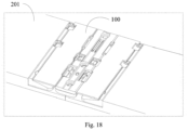
Fig. 18 is a schematic diagram of matching of a shell and a hinge assembly illustrated according to an embodiment of the disclosure. - Examples will be described in detail herein, examples of which are illustrated in the accompanying drawings. When the following description refers to the accompanying drawings, the same numbers in different drawings represent the same or similar elements unless otherwise indicated. The implementations described in the following examples do not represent all implementations consistent with the disclosure. On the contrary, they are merely examples of an apparatus and a method consistent with some aspects of the disclosure as detailed in the appended claims.
- The terms used in the disclosure are for the purpose of describing particular examples only and are not intended to limit the disclosure. As used in the disclosure and the appended claims, the singular forms "a", "the" and "this" are intended to include the plural forms as well, unless the context clearly dictates otherwise. It will also be understood that the term "and/or" as used herein refers to and includes any or all possible combinations of one or more associated listed items.
- It should be understood that although the terms first, second, third, etc. may be used in the disclosure to describe various information, such information should not be limited by these terms. These terms are only used to distinguish the same type of information from each other. For example, first information may also be referred to as second information, and similarly, the second information may also be referred to as first information, without departing from the scope of the disclosure. Depending on the context, the word "if" as used herein may be interpreted as "at the time of" or "when" or "in response to determining".
-
Fig. 1 is a schematic structural diagram of ahinge assembly 100 in an unfolded state illustrated according to an embodiment of the disclosure.Fig. 2 is a schematic diagram of a partial structure of thehinge assembly 100 inFig. 1 .Fig. 3 is an exploded schematic diagram of ahinge assembly 100 illustrated according to an embodiment of the disclosure.Fig. 4 is a schematic structural diagram of ahinge assembly 100 in a folded state illustrated according to an embodiment of the disclosure.Fig. 5 is a partial schematic diagram of ahinge assembly 100 illustrated according to an embodiment of the disclosure.Fig. 6 is an exploded schematic diagram of alocking mechanism 3 illustrated according to an embodiment of the disclosure. As shown inFig. 1-Fig. 6 , thehinge assembly 100 may include fixed supportingpieces 1, arotating assembly 2 andlocking mechanisms 3, the rotatingassembly 2 may include first limitingportions 21 and is movably connected with the fixed supportingpieces 1, and when therotating assembly 2 rotates in an axial direction of the rotating assembly 2 (i.e., a direction shown by an arrow A inFig. 2 ), a state of thehinge assembly 100 may be switched, and the fixed supportingpieces 1 may be pushed to slide relative to therotating assembly 2 in a direction perpendicular to the axial direction of therotating assembly 2, that is, when therotating assembly 2 rotates, the fixed supportingpieces 1 may be pushed to slide in the direction indicated by an arrow B inFig. 2 . - As shown in
Fig. 5 and Fig. 6 , thelocking mechanism 3 may be disposed on the fixed supportingpiece 1, thelocking mechanism 3 may include a limitingpiece 31, and the limitingpiece 31 may include second limitingportions 311. Since thelocking mechanism 3 is disposed on the fixed supportingpiece 1, when therotating assembly 2 rotates, thelocking mechanism 3 may move synchronously with the fixed supportingpiece 1, so that thelocking mechanism 3 may also move relative to therotating assembly 2 in the direction indicated by the arrow BFig. 2 , and in the process of generating relative movement between therotating assembly 2 and thelocking mechanism 3, the first limitingportions 21 and the second limitingportions 311 may be connected or separated. When the first limitingportions 21 and the second limitingportions 311 are connected, the first limitingportions 21 and the second limitingportions 311 may be matched to limit the rotation of therotating assembly 2, so that thehinge assembly 100 may be maintained in a current state, for example, it may be maintained in an unfolded state or a folded state or in any bending state between the unfolded state and the folded state; and when the first limitingportions 21 and the second limitingportions 311 are separated, limiting of therotating assembly 2 is released, and under the action of an external acting force, the rotatingassembly 2 may continue to rotate to switch the current state of thehinge assembly 100. - Based on this, through a movement relation between the
rotating assembly 2, the fixed supportingpieces 1 and the lockingmechanisms 3, the relative movement may be generated between therotating assembly 2 and the lockingmechanisms 3, the first limitingportions 21 and the second limitingportions 311 may be connected or separated, and the rotation of therotating assembly 2 may be limited by matching between the first limitingportions 21 and the second limitingportions 311, so that thehinge assembly 100 is maintained at a target position, and the state of thehinge assembly 100 may be switched when the first limitingportions 21 and the second limitingportions 311 are separated, so that when thehinge assembly 100 is applied to a foldable electronic device, the foldable electronic device may be maintained in a target bending state, and folding methods of the foldable electronic device are enriched. - In the example provided by the disclosure, the first limiting
portions 21 include concave portions disposed side by side in the direction perpendicular to the axial direction of therotating assembly 2, and the second limitingportions 311 include a plurality of convex blocks disposed side by side in an axial direction of firstrotating portions 231. During the rotation of therotating assembly 2, the fixed supportingpieces 1 slide in the direction perpendicular to the axial direction of therotating assembly 2, so that therotating assembly 2 may be limited when the convex blocks are at least partially located in the concave portions. Under the action of the external acting force, fixed supportingpieces 1 are driven to continue to slide, and the convex blocks may slide out from the current concave portions to release the limiting, as the rotatingassembly 2 continues to rotate, the convex blocks may be matched into another concave portion, and at the moment thehinge assembly 100 may be limited to another angle. That is, when the same concave portion is matched with different convex blocks for limiting, the rotatingassembly 2 may be limited to different angles, so that thehinge assembly 100 may be limited at different target bending positions. - The more the quantity of the concave portions and the convex blocks, the more angles that may limit the
rotating assembly 2, the more the hovering states of thehinge assembly 100, and at the same time, a plurality of groups of concave portions and the convex blocks that are matched with each other can improve the stability of limiting the firstrotating portions 231 to the target angle. In some other examples, the first limitingportion 21 may also include a single concave portion, and the second limitingportion 311 includes a plurality of convex blocks, so that the multi-angle limiting of therotating assembly 2 can also be realized; or, the first limitingportion 21 may also include a plurality of concave portions, and the second limitingportion 311 includes a single convex block, so that the multi-angle limiting of therotating assembly 2 can also be realized; or, in some other examples, in the case where the requirements for the limiting angle of therotating assembly 2 are not high, the first limitingportion 21 may also include a single concave portion, and the second limitingportion 311 may include a single convex block, so that single-angle limiting of therotating assembly 2 can be realized. - The specific movement process is described in the disclosure by taking the
hinge assembly 100 switching from the unfolded state to the folded state as an example. As shown inFig. 7 , the hinge assembly 100 is in the unfolded state at this time, two convex blocks of the limiting piece 31 in a direction from left to right inFig. 7 are matched with the corresponding concave portions on the rotating assembly 2, and the hinge assembly 100 is limited in the unfolded state; with the rotation of the rotating assembly 2, the fixed supporting piece 1 and the rotating assembly 2 slide relative to each other in the direction perpendicular to the axial direction of the rotating assembly 2, that is, in the direction indicated by the arrow B, the convex blocks and the concave portions that are matched with each other are disengaged inFig. 7 , the hinge assembly 100 is bent to be in a state shown inFig. 8 , at this time, three convex blocks of the limiting piece 31 in a direction from left to right inFig. 8 are matched with the corresponding concave portions on the rotating assembly 2, and at this time, the hinge assembly 100 may be limited at a position of being by 120°; and as the rotating assembly 2 rotates again, the fixed supporting piece 1 and the rotating assembly 2 slide relative to each other in the direction perpendicular to the axial direction of the rotating assembly 2, that is, in the direction indicated by the arrow B, the convex blocks and the concave portions that are matched with each other are disengaged inFig. 8 , the he hinge assembly 100 is folded to be in a state shown inFig. 9 , four convex blocks of the limiting piece 31 in the direction from left to right inFig. 8 are matched with the corresponding concave portions on the rotating assembly 2, and at this time, the hinge assembly 100 may be limited in the folded state. Similarly, the switching process of thehinge assembly 100 from the folded state to the unfolded state may refer to a relative movement sequence ofFig. 9, Fig. 8 andFig. 7 . - It should be noted that, in the example provided by the disclosure, the first limiting
portions 21 including the concave portions and the second limitingportions 311 including the convex blocks are taken as an example for illustration. In other examples, the first limitingportions 21 may include convex blocks, and the second limitingportions 311 may include concave portions, and the quantity of the concave portions and the convex blocks may refer to the example provided in the disclosure, which is not limited in the disclosure. In still other examples, one of the first limitingportions 21 or the second limitingportions 311 may also include hooks, and the other one includes hook grooves, and limiting is realized through matching of the hooks and the hook grooves. The first limitingportions 21 and the second limitingportions 311 may also include other structures configured to be matched for limiting, which will not be repeated herein. - Specifically, in the example provided by the disclosure, in order to improve the hand feeling in the process of folding or unfolding the
hinge assembly 100, the lockingmechanisms 3 may further includeelastic pieces 32, one ends of theelastic pieces 32 are connected with or abut against the fixed supportingpieces 1, the other ends may be connected with the limitingpieces 31, and a deformation direction of theelastic pieces 32 is parallel to the axial direction of therotating assembly 2, so that during the relative sliding of the fixed supportingpieces 1 and therotating assembly 2, when the convex blocks and the concave portions are in a separated state, a plane of therotating assembly 2 may abut and press the convex blocks of the limitingpieces 31, and theelastic pieces 32 are compressed, Additionally, at the moment when the convex blocks and the concave portions are about to be matched with each other, due to gaps provided by the concave portions, the elastic pieces may be reset, so that the convex blocks are pushed into the concave portions to realize the limiting. - The
elastic pieces 32 may include compression springs, one ends of the compression springs may be connected with the limitingpieces 31, and the other ends may be connected with the fixed supportingpieces 1. Or, the fixed supportingpieces 1 includeaccommodating grooves 11 and firstrotating shafts 12 located in theaccommodating grooves 11. As shown inFig. 6 , theelastic piece 32 may include a firstelastic arm 321, a secondelastic arm 322 and a first connectingportion 323, the first connectingportion 323 connects the firstelastic arm 321 with the secondelastic arm 322, the first connectingportion 323 may be disposed around the firstrotating shaft 12, the firstelastic arm 321 is connected with the limitingpiece 31, the second limitingportions 311 are disposed by protruding through a first inner wall of theaccommodating groove 11, the secondelastic arm 322 abuts against a second inner wall of theaccommodating groove 11 opposite to the first inner wall, and an elastic gap is disposed between the firstelastic arm 321 and the secondelastic arm 322. Based on this, in the sliding process of therotating assembly 2, the firstelastic arms 321 may be deformed and compressed toward the secondelastic arms 322, and at the moment when the concave portions and the convex blocks are about to be matched, the firstelastic arms 321 are reset, and the convex blocks are pushed into the concave portions to realize the limiting of therotating assembly 2. - Further, a
bent portion 324 may be disposed at a connection position between the firstelastic arm 321 and the first connectingportion 323, similarly, abent portion 324 may also be disposed at a connection position between the secondelastic arm 322 and the first connectingportion 323, and thebent portions 324 are recessed inward around a radial direction of firstrotating shafts 12, thereby reducing a diameter between two ends of the first connectingportion 323, preventing the firstrotating shafts 12 from being disengaged from the first connectingportion 323, and improving the stability of the installation of theelastic piece 32. In the example of the disclosure, thebent portions 324 disposed at the connection position between the firstelastic arm 321 and the first connectingportion 323 and the connection position between the secondelastic arm 322 and the first connectingportion 323 are taken as an example for illustration. In other examples, thebent portion 324 may also be disposed at the connection position between the firstelastic arm 321 and the first connectingportion 323 or at the connection position between the secondelastic arm 322 and the first connectingportion 323, which is not limited by the disclosure. One end of the secondelastic arm 322 away from the first connectingportion 323 is bent toward the second inner wall to abut against the second inner wall, so that a certain gap is left while the secondelastic arm 322 is limited, and deformation of theelastic piece 32 is facilitated. - In the above-mentioned example, the limiting
pieces 31 and theelastic pieces 32 being connected and matched with the fixed supportingpieces 1 are taken as an example for illustration. In other some examples, the limitingpieces 31 included in thelocking mechanism 3 may be directly disposed on the fixed supportingpieces 1, for example, may be disposed in regions where the fixed supportingpieces 1 are slidably connected with therotating assembly 2. - Further, in the example provided by the disclosure, the rotating
assembly 2 may include abase body 22,first pull rods 23 andsecond pull rods 24, one ends of thefirst pull rods 23 are rotationally connected with thebase body 22, the other ends of thefirst pull rods 23 are slidably connected with the fixed supportingpieces 1, one ends of thesecond pull rods 24 are movably connected with thebase body 22, the other ends of thesecond pull rods 24 are rotationally connected with the fixed supportingpieces 1, and the first limitingportions 21 of therotating assembly 2 are disposed at ends of thefirst pull rods 23 away from thebase body 22. When thesecond pull rods 24 move relative to thebase body 22, the fixed supportingpieces 1 may be driven to rotate relative to thebase body 22, and the fixed supportingpieces 1 gets close to or moves away from thebase body 22 at the same time. At the same time, relative sliding between thefirst pull rods 23 and the fixed supportingpieces 1 in the direction perpendicular to the axial direction of therotating assembly 2 may be generated, so that the relative position relation between the first limitingportions 21 and the second limitingportions 311 can be switched, and can realize state switching and hovering of thehinge assembly 100 at the same time. The axial direction of therotating assembly 2 may refer to an axial direction when thefirst pull rods 23 are rotationally connected with thebase body 22. - As shown in
Fig. 10 , thefirst pull rod 23 may include the firstrotating portion 231 and afirst matching portion 232 connected with the firstrotating portion 231, the firstrotating portion 231 may be rotationally connected with thebase body 22, thefirst matching portion 232 may be slidably connected with the fixed supportingpiece 1, and the first limitingportions 21 of therotating assembly 2 may be disposed on thefirst matching portion 232. For example, in the example provided by the disclosure, thefirst matching portion 232 may include a first slidingrail 2321, the fixed supportingpiece 1 may include a first slidinggroove 13, and through matching between the first slidingrail 2321 and the first slidinggroove 13, the sliding connection between the fixed supportingpiece 1 and thefirst matching portion 232 is realized. In some examples, the first slidinggroove 13 may be disposed on a surface of the fixed supportingpiece 1. In some other examples, the fixed supportingpiece 1 may include a groove structure recessed in the direction perpendicular to the axial direction of therotating assembly 2, and thefirst matching portion 232 may partially extend into the groove structure and is slidably connected with an inner wall of the groove structure, so as to reduce a thickness of thehinge assembly 100. - For example, in the example provided by the disclosure, in order to reduce the overall thickness of the
hinge assembly 100, thefirst matching portion 232 may include afirst subsection 2322 and asecond subsection 2323, thefirst subsection 2322 and thesecond subsection 2323 are respectively connected with the firstrotating portion 231, in the axial direction of the firstrotating portion 231, a certain distance is set between thefirst subsection 2322 and thesecond subsection 2323, the fixed supportingpiece 1 may include a firstconcave groove 14, a secondconcave groove 15 and a first extendingportion 16, the first extendingportion 16 is located between the firstconcave groove 14 and the secondconcave groove 15, when thefirst matching portion 232 is matched with the fixed supportingpiece 1, thefirst subsection 2322 may extend into the firstconcave groove 14 and is slidably connected with an inner wall of the firstconcave groove 14, thesecond subsection 2323 may extend into the secondconcave groove 15 and is slidably connected with an inner wall of the secondconcave groove 15, and the first extendingportion 16 may be located between thefirst subsection 2322 and thesecond subsection 2323. The sliding connection between thefirst subsection 2322 and the inner wall of the firstconcave groove 14 may be that as shown inFig. 5 , the first slidingrail 2321 or the first slidinggroove 13 is formed in a surface of the first extendingportion 16 forming the inner wall of the firstconcave groove 14. In other examples, the first slidingrail 2321 or the first slidinggroove 13 may be formed in the inner wall of the firstconcave groove 14 opposite to the surface of the first extendingportion 16, which is not limited in the disclosure; and similarly, the sliding connection between thesecond subsection 2323 and the inner wall of the secondconcave groove 15 may refer to thefirst subsection 2322, and a sliding connection mode between thesecond subsection 2323 and the inner wall of the secondconcave groove 15 and a sliding connection mode between thefirst subsection 2322 and the inner wall of the firstconcave groove 14 may be the same or different from each other. - For a structure in which the
first matching portion 232 includes thefirst subsection 2322 and thesecond subsection 2323, theaccommodating groove 11 of the fixed supportingpiece 1 may communicate with the firstconcave groove 14, thelocking mechanism 3 is disposed in theaccommodating groove 11, and the first limitingportions 21 are disposed on a side surface of thefirst subsection 2322, for example, the convex blocks or the concave portions may be formed on the side surface of thefirst subsection 2322 facing theaccommodating groove 11. Based on this, when thefirst subsection 2322 slides relative to the inner wall of the firstconcave groove 14, thefirst subsection 2322, thelocking mechanism 3 and asupport 222 may move relative to each other, so that the position relation between the first limitingportions 21 and the second limitingportions 311 is switched so as to switch the state of thehinge assembly 100. Based on this structural arrangement mode, the integrated arrangement of the overall structure on the fixed supportingpiece 1 is facilitated. - It can be understood that, in accordance with the current development trend, the
hinge assembly 100 may generally be applied to a foldable electronic device, so in order to synchronously fold screens on both sides of the electronic device, the rotatingassembly 2 may include a plurality offirst pull rods 23, at least onefirst pull rod 23 is located on a first side of thebase body 22, at least onefirst pull rod 23 is located on a second side of thebase body 22, and the first side and the second side are oppositely disposed. For example, as shown inFig. 11 and Fig. 12 , assuming that the first side is a left side inFig. 11 and Fig. 12 and the second side is a right side inFig. 11 and Fig. 12 , the plurality offirst pull rods 23 may include a left-side first pull rod and a right-side first pull rod, structures of the left-side first pull rod and the right-side first pull rod may be the same, In other words, the left-side first pull rod and the right-side first pull rod may each include the firstrotating portion 231 and thefirst matching portion 232, and a structure of thefirst matching portion 232 may refer to the structure disclosed in the above example. The firstrotating portion 231 may further includefirst guide grooves 2311 extending obliquely around the axial direction of the firstrotating portion 231. - In order to realize the synchronous movement of the left-side first pull rod and the right-side first pull rod, the rotating
assembly 2 may also include a slidingblock 4, the slidingblock 4 may include first protrudingportions 42 and second protrudingportions 43, the first protrudingportions 42 and the second protrudingportions 43 are disposed on two opposite surfaces of the slidingblock 4, the first protrudingportions 42 face the left-side first pull rod, and the first protrudingportions 42 may extend into thefirst guide grooves 2311 of the left-side first pull rod; and the second protrudingportions 43 may face the right-side first pull rod, and the second protrudingportions 43 may extend into thefirst guide grooves 2311 of the right-side first pull rod. Based on this, when the left-side first pull rod rotates relative to thebase body 22, the slidingblock 4 may be driven to slide along thebase body 22 through the first protrudingportions 42, and then the right-side first pull rod may be driven through the second protrudingportions 43 to rotate relative to thebase body 22. Similarly, when the right-side first pull rod rotates relative to thebase body 22, the slidingblock 4 may be driven to slide along thebase body 22 through the second protrudingportions 43, and then the left-side first pull rod is driven through the first protrudingportions 42 to rotate relative to thebase body 22, so that the synchronous movement of the left-side first pull rod and the right-side first pull rod is realized. Compared with a technical solution of using a gear set to realize synchronous movement in the related art, the thickness of thehinge assembly 100 may be reduced by reducing a shaft diameter of the firstrotating portion 231 and a thickness of the slidingblock 4, which is beneficial to the lightening and thinning of thehinge assembly 100. - The sliding connection between the
base body 22 and the slidingblock 4 may be realized in the following manner: thebase body 22 may include aguide block 221, the slidingblock 4 may include asecond guide groove 41, and theguide block 221 may extend into thesecond guide groove 41, so that with matching of theguide block 221 and thesecond guide groove 41, when anyfirst pull rod 23 rotates relative to thebase body 22, the slidingblock 4 may be driven to slide in the axial direction of the firstrotating portion 231. In other examples, thebase body 22 may also include asecond guide groove 41, and the slidingblock 4 may include aguide block 221, which is not limited in the disclosure. In order to improve the aesthetics of thehinge assembly 100, thebase body 22 may include asupport 222 and acover body 223 assembled with thesupport 222, and the firstrotating portion 231 may be rotationally connected with a shaft hole formed by assembling thesupport 222 and thecover body 223 in a matched mode, so as to reduce the assembling difficulty of thefirst pull rod 23, and theguide block 221 may be disposed between thecover body 223 and thesupport 222, so as to prevent the protrusion of the guide block 221 from interfering with other parts. - The fixed supporting
pieces 1 may include a first fixed supporting piece located on the first side of thebase body 22 and a second fixed supporting piece located on the second side when thehinge assembly 100 is in the unfolded state, the first fixed supporting piece may be rotationally connected with the left-side first pull rod, the second fixed supporting piece may be rotationally connected with the right-side first pull rod, the first fixed supporting piece may be connected with a shell on one side of the electronic device, and the second fixed supporting piece may be connected with a shell on the other side of the electronic device, so that when the first fixed supporting piece and the second fixed supporting piece move relative to thebase body 22, the shells on two sides of the electronic device may be driven to get close to each other or move away from each other, thereby realizing the folding and unfolding of the electronic device. - In the example, the
hinge assembly 100 may include a plurality of lockingmechanisms 3, one of the lockingmechanisms 3 is disposed on the first fixed supporting piece, and thelocking mechanism 3 disposed on the first fixed supporting piece may be matched with the left-side first pull rod for limiting; and onelocking mechanism 3 is disposed on the second fixed supporting piece, and thelocking mechanism 3 disposed on the second fixed supporting piece may be matched with the right-side first pullrod 23 for limiting, and through the simultaneous action of the plurality of lockingmechanisms 3, the stability of thehinge assembly 100 in any state can be improved. The matching between the first fixed supporting piece and the left-side first pull rod may refer to the foregoing examples, and the matching between the second fixed supporting piece and the right-side first pull rod may also refer to the foregoing examples. In the example of the disclosure, the lockingmechanisms 3 respectively disposed on the first fixed supporting piece and the second fixed supporting piece are taken as an example for illustration. In other examples, thelocking mechanism 3 may also be disposed on any one of the first fixed supporting piece and the second fixed supporting piece, which is not limited in the disclosure. - As shown in
Fig. 13 , thesecond pull rod 24 may include amovable portion 241, a secondrotating portion 242 and a second connectingportion 243, the second connectingportion 243 connects themovable portion 241 with the secondrotating portion 242, themovable portion 241 is movably connected with thebase body 22, and the secondrotating portion 242 is rotationally connected with the fixed supportingpiece 1. Based on this, when themovable portion 241 moves relative to thebase body 22, the secondrotating portion 242 may be pushed to move in a length direction of thesecond pull rod 24, and the secondrotating portion 242 may drive the fixed supportingpiece 1 to rotate relative to thebase body 22 and push the fixed supportingpiece 1 to get close to or move away from thebase body 22. Therefore, in the case where the fixed supportingpieces 1 are disposed on both sides of thebase body 22, the first side of thebase body 22 is a left side inFig. 13 , and the second side of thebase body 22 is a right side inFig. 14 , then therotating assembly 2 may include a left-side second pull rod and a right-side second pull rod, one end of the left-side second pull rod may be movably connected with thebase body 22, and the other end may be rotationally connected with the first fixed supporting piece; and one end of the right-side second pull rod may be movably connected with thebase body 22, and the other end may be rotationally connected with the second fixed supporting piece, so that the first fixed supporting piece is pushed to move through the left-side second pull rod, and the second fixed supporting piece is pushed to move through the right-side second pull rod. When thehinge assembly 100 is switched from the folded state to the unfolded state, both the first fixed supporting piece and the second fixed supporting piece may move close to thebase body 22, and the first fixed supporting piece and the second fixed supporting piece may get close to each other at a back surface of thebase body 22 so as to shield thebase body 22, so that the back surface of thehinge assembly 100 is flat and the aesthetics is improved; and when thehinge assembly 100 is switched from the unfolded state to the folded state, both the first fixed supporting piece and the second fixed supporting piece may move away from thebase body 22 until the folded state shown inFig. 4 , so that the first fixed supporting piece and the second fixed supporting piece are prevented from interfering with flexible screens. - For the movable connection between the
movable portion 241 and thebase body 22, specifically, thebase body 22 may include a first arc-shapedtrack 224, themovable portion 241 may include an arc-shaped movable portion, such as a semicircular arc-shaped movable portion, and the arc-shaped movable portion extends from an end portion into the first arc-shapedtrack 224 to be matched with the first arc-shapedtrack 224. Based on this, when the arc-shaped movable portion moves in the first arc-shapedtrack 224, on the one hand, the relative rotation of thesecond pull rod 24 and thebase body 22 may be realized, and at the same time, position change between the arc-shaped movable portion and the first arc-shapedtrack 224 makes the secondrotating portion 242 move away from or get close to thebase body 22, thereby driving the fixed supportingpiece 1 to move away from or get close to thebase body 22. - In order to facilitate the installation, the
support 222 of thebase body 22 may include a first arc-shapedconcave portion 2221, and thecover body 223 of thebase body 22 may include a first arc-shapedconvex portion 2231, for example, the first arc-shapedconcave portion 2221 may be disposed in a semicircular shape, and the first arc-shapedconvex portion 2231 may also be disposed in a semicircular shape, but a radius of the first arc-shapedconvex portion 2231 is smaller than a radius of the first arc-shapedconcave portion 2221, so that when the first arc-shapedconvex portion 2231 is matched with the first arc-shapedconcave portion 2221, the first arc-shapedtrack 224 may be formed due to the difference in radius. The first arc-shapedconvex portion 2231 and the first arc-shapedconcave portion 2221 disposed in the semicircular shape are taken as an example for illustration, in other examples, other forming modes may also be included as long as displacement change may be generated while themovable portion 241 rotates relative to the first arc-shapedtrack 224. - In each of the above-mentioned examples, as shown in
Fig. 14 and Fig. 15 , the rotatingassembly 2 may also include ascreen supporting piece 25 and athird pull rod 26, thescreen supporting piece 25 and the fixed supportingpiece 1 may be disposed in a stacked mode, thescreen supporting piece 25 includes a plate-shapedbody 251, a second extendingportion 252 extending from the plate-shapedbody 251, and an inclined slidinggroove 253 disposed on the second extendingportion 252; and one end of thethird pull rod 26 is rotationally connected with thebase body 22, the other end is slidably connected with the fixed supportingpiece 1, thethird pull rod 26 includes a third protrudingportion 261, and the third protrudingportion 261 may extend into the inclined slidinggroove 253. Based on this, when thethird pull rod 26 rotates relative to thebase body 22, the third protrudingportion 261 slides in the inclined slidinggroove 253 and push thescreen supporting piece 25 to rotate relative to thebase body 22. Therefore, when thehinge assembly 100 is in the folded state, one flexible screen of the electronic device with thehinge assembly 100 may be supported by the screen supporting piece, so that the deformation of the flexible screen is reduced. For example, as shown inFig. 15 , asecond guide rail 262 may be disposed at one end of thethird pull rod 26 close to the fixed supportingpiece 1, a second sliding groove may be disposed in the fixed supportingpiece 1, and sliding connection between thethird pull rod 26 and the fixed supportingpiece 1 is realized through the cooperation of the second sliding groove and thesecond guide rail 262. - In order to guide and limit the movement of the
screen supporting piece 25 relative to thebase body 22, as shown inFig. 3 , thehinge assembly 100 may also include a supportingplate cover body 5, the supportingplate cover body 5 may include a second arc-shapedconvex portion 51, the fixed supportingpiece 1 may include a second arc-shapedconcave portion 17, the second arc-shapedconcave portion 17 is located at an edge of one side of the fixed supportingpiece 1 away from thefirst pull rod 23, and the second arc-shapedconvex portion 51 of the supportingplate cover body 5 may be disposed in the second arc-shapedconcave portion 17 to be matched with the second arc-shapedconcave portion 17 to form a second arc-shaped track. Thescreen supporting piece 25 may include an arc-shapedguide piece 254 disposed on an edge of the plate-shapedbody 251, the plate-shapedbody 251 and the fixed supportingpiece 1 are disposed in a stacked mode, and the arc-shapedguide piece 254 is matched with the second arc-shaped track. Based on this, in the movement process of the fixed supportingpiece 1 relative to thebase body 22, thescreen supporting piece 25 may move adaptively to avoid being stuck. - The second arc-shaped
convex portion 51 may be disposed in a semicircular shape, a cross section of the second arc-shapedconcave portion 17 may be disposed in a semicircular shape, and a radius of the second arc-shapedconvex portion 51 may be smaller than a radius of the second arc-shapedconcave portion 17, so that when the second arc-shapedconvex portion 51 is located in the second arc-shapedconcave portion 17, the second arc-shaped track may be formed. The arc-shapedguide piece 254 of thescreen supporting piece 25 may be an arc-shaped plate with a semicircular cross section. The second arc-shaped track and the arc-shapedguide piece 254 which are both semicircular are taken as an example for illustration. In other examples, the second arc-shaped track and the arc-shapedguide piece 254 may also be disposed in other arc shapes, which is not limited in the disclosure. - In the above-mentioned example, the
third pull rod 26 pushes thescreen supporting piece 25 to move, and it may be avoided that a structure is disposed on thefirst pull rods 23 to push thescreen supporting piece 25, so that the problems of the complex stress and limited space on thefirst pull rods 23 can be solved. In other examples, thescreen supporting piece 25 may also be pushed to move through thefirst pull rods 23, specific implementations may refer to the matching between thethird pull rod 26 and thescreen supporting piece 25, and compared with a solution in which thethird pull rod 26 is adopted to push thescreen supporting piece 25, the structure of thehinge assembly 100 can be simplified. In the example provided by the disclosure, in order to adapt to application objects of the first fixed supporting piece, the second fixed supporting piece and thehinge assembly 100, the rotatingassembly 2 may include a plurality ofscreen supporting pieces 25 and a plurality ofthird pull rods 26, onescreen supporting piece 25 and the first fixed supporting piece are disposed in a matched mode, one end of onethird pull rod 26 is rotationally connected with thebase body 22, and the other end of thethird pull rod 26 is slidably connected with the first fixed supporting piece; and onescreen supporting piece 25 and the second fixed supporting piece are disposed in a matched mode, one end of onethird pull rod 26 is rotationally connected with thebase body 22, and the other end of thethird pull rod 26 is slidably connected with the second fixed supporting piece. - In the example provided by the disclosure, a thickness of the fixed supporting
pieces 1 increases incrementally from one side close to thebase body 22 to one side away from thebase body 22, that is, a thickness of the fixed supportingpiece 1 on the right side inFig. 11 increases incrementally in a direction from left to right, and a thickness of the fixed supportingpiece 1 on the left side increases incrementally in the direction from right to left. Therefore, as shown inFig. 10 , when thehinge assembly 100 is switched in the folded state, a bending radius of thebent portion 324 of the flexible screen is the largest, and the flexible screen away from thebent portion 324 is disposed oppositely, so that by incrementally increasing the thicknesses of the fixed supportingpieces 1, regions with the smaller thickness of the fixed supportingpieces 1 are closer to the bent region of the flexible screen than regions with the larger thickness, so as to adapt to the shape change of the flexible screen from the unfolded state to the folded state, and squeezing of the flexible screen by the fixed supportingpieces 1 is avoided. - Based on the technical solution of the disclosure, as shown in
Fig. 16-Fig. 18 , the disclosure also provides anelectronic device 200. Theelectronic device 200 may include ashell 201,flexible screens 202 and ahinge assembly 100. Theflexible screens 202 may be laid flat on theshell 201, one end of arotating assembly 2 of thehinge assembly 100 away from firstrotating portions 231 is configured to be connected to theshell 201, for example, firstrotating portions 231 may be connected to theshell 201 through fixed supportingpieces 1, so as to drive theshell 201 to rotate, and the switching of theelectronic device 200 between an unfolded state shown inFig. 13 and a folded state shown inFig. 14 is realized. - Specifically, the
shell 201 may include a left shell and a right shell, theflexible screens 202 are laid flat on the left shell and the right shell, the left shell may be connected with the fixed supportingpiece 1 on one side of thehinge assembly 100, and the right shell may be connected with the fixed supportingpiece 1 on the other side of thehinge assembly 100. Based on this, when thehinge assembly 100 is bent, the two fixed supportingpieces 1 of thehinge assembly 100 will get close to or move away from each other, so that the left shell and the right shell are driven to get close to or move away from each other, and theflexible screens 202 are synchronously bent or unfolded. - Other implementation solutions of the disclosure will be apparent to those skilled in the art from consideration of the specification and practice of the disclosure herein. The disclosure is intended to cover any variations, uses, or adaptations of the disclosure following the general principles thereof and including such departures from the disclosure as come within known or customary practice in the art. It is intended that the specification and examples be considered as exemplary only, with a true scope of the disclosure being indicated by the following claims.
- It will be appreciated that the disclosure is not limited to the exact construction that has been described above and illustrated in the accompanying drawings, and that various modifications and changes may be made without departing from the scope thereof. It is intended that the scope of the disclosure only be limited by the appended claims.
Claims (15)
- A hinge assembly, comprising:a fixed supporting piece (1);a rotating assembly (2), movably connected with the fixed supporting piece (1) and comprising a first limiting portion (21); anda locking mechanism (3), the locking mechanism (3) is on the fixed supporting piece (1) and comprising a limiting piece (31) which comprises a second limiting portion (311) matched with the first limiting portion (21);wherein the fixed supporting piece (1) is configured to slide relative to the rotating assembly (2) in a direction perpendicular to an axial direction of the rotating assembly (2) in a rotation process of the rotating assembly (2), so that the first limiting portion (21) is connected with the second limiting portion (311) or the first limiting portion (21) is separated from the second limiting portion (311);, the first limiting portion (21) and the second limiting portion (311) are configured to match with each other to limit rotation of the rotating assembly (2) when the first limiting portion (21) is connected with the second limiting portion (311); and the rotating assembly (2) is configured to release the limit when the first limiting portion (21) is separated from the second limiting portion (311).
- The hinge assembly according to claim 1, wherein the locking mechanism (3) comprises an elastic piece (32), one end of the elastic piece (32) is connected with or abuts against the fixed supporting piece (1), the other end of the elastic piece (32) is connected with the limiting piece (31), and a deformation direction of the elastic piece (32) is parallel with the axial direction of the rotating assembly (2) ;optionally, the fixed supporting piece (1) comprises an accommodating groove (11) and a first rotating shaft (12) located in the accommodating groove (11);the elastic piece (32) comprises a first elastic arm (321), a second elastic arm (322) and a first connecting portion (323) connecting the first elastic arm (321) with the second elastic arm (322), the first connecting portion (323) is around the first rotating shaft (12), the first elastic arm (321) is connected with the limiting piece (31), and an elastic gap is between the first elastic arm (321) and the second elastic arm (322); andthe second limiting portion (311) protrudes through a first inner wall of the accommodating groove (11), and the second elastic arm (322) abuts against a second inner wall of the accommodating groove (11) opposite to the first inner wall ;optionally, a bent portion (324) which is at a connection position between the first elastic arm (321) and the first connecting portion (323) and/or at a connection position between the second elastic arm (322) and the first connecting portion (323); andone end of the second elastic arm (322) away from the first connecting portion (323) is bent toward the second inner wall to abut against the second inner wall.
- The hinge assembly according to claim 1 or claim 2, wherein one of the first limiting portion (21) and the second limiting portion (311) comprises at least one convex block disposed side by side in the direction perpendicular to the axial direction of the rotating assembly (2), and the other one comprises at least one concave portion, wherein the same convex block is configured to be matched with different concave portions, so as to limit the first limiting portion (21) at different angles; and
wherein the fixed supporting piece (1) is configured to slide in the direction perpendicular to the axial direction of the rotating assembly (2) in the rotation process of the rotating assembly (2), so that when the convex block is at least partially located in the concave portion, rotation of the rotating assembly (2) is limited, and the rotating assembly is configured to release the limit when the convex block is separated from the concave portion. - The hinge assembly according to any one of claims 1-3, wherein the rotating assembly (2) comprises:a base body (22);a first pull rod (23), wherein one end of the first pull rod (23) is rotationally connected with the base body (22), the other end is slidably connected with the fixed supporting piece (1), and the first limiting portion (21) is located at an end of the first pull rod (23) away from the base body (22); anda second pull rod (24), wherein one end of the second pull rod (24) is movably connected with the base body (22), and the other end is rotationally connected with the fixed supporting piece (1);wherein the fixed supporting piece (1) is configured to be driven to rotate relative to the base body (22), and get close to or move away from the base body (22), and the fixed supporting piece (1) and the first pull rod (23) are configured to slide relatively so as to switch a relative position relation between the first limiting portion (21) and the second limiting portion (311) when the second pull rod (24) moves relative to the base body (22);optionally, the first pull rod (23) comprises a first rotating portion (231) and a first matching portion (232) connected with the first rotating portion (231), the first rotating portion (231) is rotationally connected with the base body (22), the first matching portion (232) is slidably connected with the fixed supporting piece (1), and the first limiting portion (21) is on the first matching portion (232).
- The hinge assembly according to claim 4, wherein one of the first matching portion (232) and the fixed supporting piece (1) comprises a first sliding groove (13), and the other one comprises a first sliding rail (2321).
- The hinge assembly according to claim 4 or claim 5, wherein the first matching portion (232) comprises a first subsection (2322) and a second subsection (2323) which are respectively connected with the first rotating portion (231) and disposed at an interval in an axial direction of the first rotating portion (231), the fixed supporting piece (1) comprises a first concave groove (14), a second concave groove (15), and a first extending portion (16) located between the first concave groove (14) and the second concave groove (16), the first subsection (2322) is in the first concave groove (14) and slidably connected with an inner wall of the first concave groove (14), and the second subsection (2323) is in the second concave groove (15) and slidably connected with an inner wall of the second concave groove (15);
optionally, the first limiting portion (21) is in the first subsection (2322), the fixed supporting piece (1) comprises an accommodating groove (11), the accommodating groove (11) communicates with the first concave groove (14), and the locking mechanism (3) is in the accommodating groove (11). - The hinge assembly according to any one of claims 4-6, wherein the rotating assembly (2) comprises a plurality of first pull rods (23), each first pull rod (23) is rotationally connected with the base body (22) and comprises the first rotating portion (231) and the first matching portion (232) respectively, the first rotating portion (231) comprises a first guide groove (2311) extending obliquely around an axial direction of the first rotating portion (231), wherein at least one first pull rod (23) is located on a first side of the base body (22), at least one first pull rod (23) is located on a second side of the base body (22) and the first side and the second side are oppositely disposed; andthe rotating assembly (2) further comprises a sliding block (4), the sliding block (4) comprises a first protruding portion (42) and a second protruding portion (43) which are on two opposite surfaces, the first protruding portion (42) extends into the first guide groove (2311) of the first pull rod (321) located on the first side of the base body (22), the second protruding portion (43) extends into the first guide groove (2311) of the first pull rod (23) on the second side of the base body (22), and the sliding block (4) is configured to be driven to slide when any one of the first pull rods (23) rotates relative to the base body (22), so that the other one rotates relative to the base body (22);optionally, one of the base body (22) and the sliding block (4) comprises a guide block (221), and the other one comprises a second guide groove (41) matched with the guide block (221).
- The hinge assembly according to claim 7, wherein the fixed supporting piece (1) comprises a first fixed supporting piece and a second fixed supporting piece, the first fixed supporting piece is slidably connected with the first pull rod (23) located on the first side of the base body (22), and the second fixed supporting piece is slidably connected with the first pull rod (23) located on the second side of the base body (22); and
wherein the locking mechanism (3) is on the first fixed supporting piece and/or the second fixed supporting piece, the locking mechanism (3) on the first fixed supporting piece is matched with the first pull rod (23) located on the first side of the base body (22) for limiting, and the locking mechanism (3) on the second fixed supporting piece is matched with the first pull rod (23) located on the second side of the base body (22) for limiting. - The hinge assembly according to any one of claims 4-8, wherein the second pull rod (24) comprises a movable portion (241), a second rotating portion (242) and a second connecting portion (243), the second connecting portion (243) connects the movable portion (241) with the second rotating portion (242), the movable portion (241) is movably connected with the base body (22), and the second rotating portion (243) is rotationally connected with the fixed supporting piece (1).
- The hinge assembly according to claim 9, wherein the base body (22) comprises a first arc-shaped track (224), the movable portion (241) comprises an arc-shaped movable portion, the arc-shaped movable portion extends into the first arc-shaped track (224), and the fixed supporting piece (1) is configured to gradually move away from or get close to the base body (22) when the movable portion (241) moves along the first arc-shaped track (224), and a first matching portion (232) is configured to slide relative to the fixed supporting piece (1).
- The hinge assembly according to claim 10, wherein the base body (22) comprises a support (222) and a cover body (223), the support (222) comprises a first arc-shaped concave portion (2221), the cover body (223) comprises a first arc-shaped convex portion (2231), and the first arc-shaped convex portion (2231) is in the first arc-shaped concave portion (2221) to form the first arc-shaped track (224) in a matched mode.
- The hinge assembly according to any one of claims 4-11, wherein the rotating assembly further comprises:a screen supporting piece (25), wherein the screen supporting piece (25) and the fixed supporting piece (1) are disposed in a stacked mode, and the screen supporting piece (25) comprises a plate-shaped body (251), a second extending portion (252) extending from the plate-shaped body (251), and an inclined sliding groove (253) on the second extending portion (252); anda third pull rod (26), wherein one end of the third pull rod (26) is rotationally connected with the base body (22), the other end is slidably connected with the fixed supporting piece (1), the third pull rod (26) comprises a third protruding portion (261), the third protruding portion (261) extends into the inclined sliding groove (253), and the third protruding portion (261) is configured to slide in the inclined sliding groove (253) and pushes the screen supporting piece (25) to rotate relative to the base body (22) when the third pull rod (261) rotates relative to the base body (22).
- The hinge assembly according to claim 12, wherein the hinge assembly (100) further comprises a supporting plate cover body (5), the fixed supporting piece (1) comprises a second arc-shaped concave portion, the second arc-shaped concave portion is located at an edge of the fixed supporting piece (1) away from the first pull rod (23), the supporting plate cover body (5) comprises a second arc-shaped convex portion (51), and the second arc-shaped convex portion (51) is in the second arc-shaped concave portion to form a second arc-shaped track in a matched mode; and
the screen supporting piece (25) comprises an arc-shaped guide piece (254) on an edge of the plate-shaped body (251), the plate-shaped body (251) and the fixed supporting piece (1) are in a stacked mode, and the arc-shaped guide piece (254) is matched with the second arc-shaped track. - The hinge assembly according to any one of claims 1-13, wherein a thickness of the fixed supporting piece (1) increases incrementally from one end close to the rotating assembly (2) to one end away from the rotating assembly (2).
- An electronic device, comprising:a shell (201); andthe hinge assembly (100) according to any one of claims 1-14, wherein the fixed supporting piece (1) is connected to the shell (201) so as to drive the shell (201) to rotate.
Priority Applications (1)
| Application Number | Priority Date | Filing Date | Title |
|---|---|---|---|
| EP25201487.3A EP4642016A3 (en) | 2021-08-12 | 2022-02-24 | HINGE ARRANGEMENT AND ELECTRONIC DEVICE |
Applications Claiming Priority (1)
| Application Number | Priority Date | Filing Date | Title |
|---|---|---|---|
| CN202110926287.0A CN115705074A (en) | 2021-08-12 | 2021-08-12 | Hinge components and electronics |
Related Child Applications (2)
| Application Number | Title | Priority Date | Filing Date |
|---|---|---|---|
| EP25201487.3A Division-Into EP4642016A3 (en) | 2021-08-12 | 2022-02-24 | HINGE ARRANGEMENT AND ELECTRONIC DEVICE |
| EP25201487.3A Division EP4642016A3 (en) | 2021-08-12 | 2022-02-24 | HINGE ARRANGEMENT AND ELECTRONIC DEVICE |
Publications (2)
| Publication Number | Publication Date |
|---|---|
| EP4134782A1 true EP4134782A1 (en) | 2023-02-15 |
| EP4134782B1 EP4134782B1 (en) | 2025-10-22 |
Family
ID=80461441
Family Applications (2)
| Application Number | Title | Priority Date | Filing Date |
|---|---|---|---|
| EP25201487.3A Pending EP4642016A3 (en) | 2021-08-12 | 2022-02-24 | HINGE ARRANGEMENT AND ELECTRONIC DEVICE |
| EP22158623.3A Active EP4134782B1 (en) | 2021-08-12 | 2022-02-24 | Hinge assembly and electronic device |
Family Applications Before (1)
| Application Number | Title | Priority Date | Filing Date |
|---|---|---|---|
| EP25201487.3A Pending EP4642016A3 (en) | 2021-08-12 | 2022-02-24 | HINGE ARRANGEMENT AND ELECTRONIC DEVICE |
Country Status (3)
| Country | Link |
|---|---|
| US (1) | US12085123B2 (en) |
| EP (2) | EP4642016A3 (en) |
| CN (1) | CN115705074A (en) |
Families Citing this family (9)
| Publication number | Priority date | Publication date | Assignee | Title |
|---|---|---|---|---|
| USD1043599S1 (en) * | 2020-12-11 | 2024-09-24 | Samsung Display Co., Ltd. | Display device |
| CN113883158B (en) * | 2021-09-26 | 2022-05-20 | 维沃移动通信有限公司 | Electronic device |
| CN116498642B (en) * | 2022-01-18 | 2024-03-29 | 荣耀终端有限公司 | A synchronization mechanism, a rotating shaft mechanism and an electronic device |
| CN117157465B (en) * | 2022-03-31 | 2026-04-07 | 京东方科技集团股份有限公司 | Hinge device and foldable display device |
| WO2023245382A1 (en) * | 2022-06-20 | 2023-12-28 | 北京小米移动软件有限公司 | Hinge structure and electronic device |
| CN117319530B (en) * | 2022-06-22 | 2024-09-06 | 荣耀终端有限公司 | Synchronous rotation mechanism and foldable electronic device |
| CN116255389B (en) * | 2023-03-17 | 2026-01-13 | 北京蜂巢世纪科技有限公司 | Double-rotating-shaft connecting piece and glasses |
| CN117351844B (en) * | 2023-11-21 | 2024-04-09 | 荣耀终端有限公司 | Rotating mechanism and foldable electronic device |
| CN121363583A (en) * | 2024-07-19 | 2026-01-20 | 北京小米移动软件有限公司 | Hinge mechanism and foldable electronic device |
Citations (3)
| Publication number | Priority date | Publication date | Assignee | Title |
|---|---|---|---|---|
| EP3355157A1 (en) * | 2017-01-26 | 2018-08-01 | Guangdong OPPO Mobile Telecommunications Corp., Ltd. | Housing assembly and electronic device |
| CN112128216A (en) * | 2019-06-25 | 2020-12-25 | 深圳市富世达通讯有限公司 | Folding screen device and hinge mechanism |
| WO2021115462A1 (en) * | 2019-12-13 | 2021-06-17 | 华为技术有限公司 | Rotary shaft mechanism and electronic device |
Family Cites Families (13)
| Publication number | Priority date | Publication date | Assignee | Title |
|---|---|---|---|---|
| US10824204B2 (en) * | 2018-02-14 | 2020-11-03 | Compal Electronic, Inc. | Hinge module and foldable electronic device |
| CN113090149B (en) * | 2019-12-23 | 2022-08-09 | 北京小米移动软件有限公司 | Hinge structure and folding electronic device |
| EP4395289B1 (en) * | 2019-12-27 | 2026-02-04 | Huawei Technologies Co., Ltd. | Electronic device |
| CN115695607B (en) * | 2019-12-27 | 2023-05-05 | 华为技术有限公司 | A flexible screen and foldable device |
| CN111588155B (en) * | 2020-05-14 | 2021-12-07 | 湖南万信达科技制品有限公司 | Changeable multi-functional suitcase of volume |
| JP7557334B2 (en) * | 2020-10-16 | 2024-09-27 | 株式会社ハイレックスコーポレーション | Cable connection mechanism |
| WO2022133708A1 (en) * | 2020-12-22 | 2022-06-30 | Intel Corporation | Automatically open laptop hinge |
| CN116568936A (en) * | 2020-12-29 | 2023-08-08 | 泛泰科技株式会社 | Hinge device for portable terminal with foldable structure |
| EP4254917B1 (en) * | 2021-01-29 | 2025-06-11 | Samsung Electronics Co., Ltd. | Electronic device comprising hinge structure |
| CN115370655B (en) * | 2021-05-18 | 2024-06-25 | 北京小米移动软件有限公司 | Rotating modules and electronic devices |
| EP4283433A4 (en) * | 2021-06-29 | 2024-10-02 | Samsung Electronics Co., Ltd. | Hinge assembly and electronic device comprising same |
| EP4332721A4 (en) * | 2021-09-07 | 2024-08-21 | Samsung Electronics Co., Ltd. | Hinge assembly and electronic device comprising same |
| EP4429215A4 (en) * | 2021-12-08 | 2025-02-26 | Samsung Electronics Co., Ltd. | HINGE ASSEMBLY AND ELECTRONIC DEVICE COMPRISING IT |
-
2021
- 2021-08-12 CN CN202110926287.0A patent/CN115705074A/en active Pending
-
2022
- 2022-02-24 EP EP25201487.3A patent/EP4642016A3/en active Pending
- 2022-02-24 EP EP22158623.3A patent/EP4134782B1/en active Active
- 2022-02-25 US US17/681,394 patent/US12085123B2/en active Active
Patent Citations (3)
| Publication number | Priority date | Publication date | Assignee | Title |
|---|---|---|---|---|
| EP3355157A1 (en) * | 2017-01-26 | 2018-08-01 | Guangdong OPPO Mobile Telecommunications Corp., Ltd. | Housing assembly and electronic device |
| CN112128216A (en) * | 2019-06-25 | 2020-12-25 | 深圳市富世达通讯有限公司 | Folding screen device and hinge mechanism |
| WO2021115462A1 (en) * | 2019-12-13 | 2021-06-17 | 华为技术有限公司 | Rotary shaft mechanism and electronic device |
Also Published As
| Publication number | Publication date |
|---|---|
| US20230047119A1 (en) | 2023-02-16 |
| EP4134782B1 (en) | 2025-10-22 |
| EP4642016A2 (en) | 2025-10-29 |
| CN115705074A (en) | 2023-02-17 |
| US12085123B2 (en) | 2024-09-10 |
| EP4642016A3 (en) | 2025-12-31 |
Similar Documents
| Publication | Publication Date | Title |
|---|---|---|
| EP4642016A2 (en) | Hinge assembly and electronic device | |
| CN111614806B (en) | Folding device and electronic equipment | |
| US11336759B2 (en) | Rotating shaft mechanism and mobile terminal | |
| EP4134780B1 (en) | Hinge assembly and electronic device | |
| CN113542457B (en) | Folding device and electronic equipment | |
| JP2023521480A (en) | Folding devices and electronic devices | |
| CN117419098B (en) | Rotating mechanism and foldable electronic device | |
| CN217849479U (en) | Rotating shaft mechanism and foldable equipment | |
| WO2022206276A1 (en) | Rotating assembly, folding mechanism, and foldable terminal | |
| CN116085377B (en) | Hinge parts and electronic devices | |
| CN117515016A (en) | A rotating shaft mechanism and electronic equipment | |
| CN112128221A (en) | Hinge mechanism and mobile terminal | |
| CN217502265U (en) | Rotating mechanism and electronic equipment | |
| JP7709613B2 (en) | Rotating shaft mechanism and electronic device | |
| CN214661469U (en) | Double axis hinge | |
| JP2024533781A (en) | Rotating shaft mechanism and electronic device | |
| WO2023045337A1 (en) | Hinge component and electronic device | |
| CN117351844A (en) | Rotating mechanisms and foldable electronics | |
| JP7775500B2 (en) | Hinge mechanism and electronic device | |
| CN118224173B (en) | Foldable electronic equipment and hinge | |
| CN219317422U (en) | Rotary connecting mechanism, foldable shell assembly and foldable electronic equipment | |
| CN219865869U (en) | Folding mechanism and electronic equipment | |
| WO2025001267A1 (en) | Rotating shaft mechanism and electronic device | |
| WO2025261196A1 (en) | Folding mechanism and electronic device | |
| CN120062227A (en) | Hinge and electronic device |
Legal Events
| Date | Code | Title | Description |
|---|---|---|---|
| PUAI | Public reference made under article 153(3) epc to a published international application that has entered the european phase |
Free format text: ORIGINAL CODE: 0009012 |
|
| STAA | Information on the status of an ep patent application or granted ep patent |
Free format text: STATUS: REQUEST FOR EXAMINATION WAS MADE |
|
| 17P | Request for examination filed |
Effective date: 20220224 |
|
| AK | Designated contracting states |
Kind code of ref document: A1 Designated state(s): AL AT BE BG CH CY CZ DE DK EE ES FI FR GB GR HR HU IE IS IT LI LT LU LV MC MK MT NL NO PL PT RO RS SE SI SK SM TR |
|
| RBV | Designated contracting states (corrected) |
Designated state(s): AL AT BE BG CH CY CZ DE DK EE ES FI FR GB GR HR HU IE IS IT LI LT LU LV MC MK MT NL NO PL PT RO RS SE SI SK SM TR |
|
| GRAP | Despatch of communication of intention to grant a patent |
Free format text: ORIGINAL CODE: EPIDOSNIGR1 |
|
| STAA | Information on the status of an ep patent application or granted ep patent |
Free format text: STATUS: GRANT OF PATENT IS INTENDED |
|
| INTG | Intention to grant announced |
Effective date: 20250514 |
|
| GRAS | Grant fee paid |
Free format text: ORIGINAL CODE: EPIDOSNIGR3 |
|
| GRAA | (expected) grant |
Free format text: ORIGINAL CODE: 0009210 |
|
| STAA | Information on the status of an ep patent application or granted ep patent |
Free format text: STATUS: THE PATENT HAS BEEN GRANTED |
|
| AK | Designated contracting states |
Kind code of ref document: B1 Designated state(s): AL AT BE BG CH CY CZ DE DK EE ES FI FR GB GR HR HU IE IS IT LI LT LU LV MC MK MT NL NO PL PT RO RS SE SI SK SM TR |
|
| P01 | Opt-out of the competence of the unified patent court (upc) registered |
Free format text: CASE NUMBER: UPC_APP_6972_4134782/2025 Effective date: 20250912 |
|
| REG | Reference to a national code |
Ref country code: CH Ref legal event code: F10 Free format text: ST27 STATUS EVENT CODE: U-0-0-F10-F00 (AS PROVIDED BY THE NATIONAL OFFICE) Effective date: 20251022 Ref country code: GB Ref legal event code: FG4D |
|
| REG | Reference to a national code |
Ref country code: DE Ref legal event code: R096 Ref document number: 602022023295 Country of ref document: DE |
|
| REG | Reference to a national code |
Ref country code: IE Ref legal event code: FG4D |
|
| REG | Reference to a national code |
Ref country code: NL Ref legal event code: MP Effective date: 20251022 |
|
| PG25 | Lapsed in a contracting state [announced via postgrant information from national office to epo] |
Ref country code: NL Free format text: LAPSE BECAUSE OF FAILURE TO SUBMIT A TRANSLATION OF THE DESCRIPTION OR TO PAY THE FEE WITHIN THE PRESCRIBED TIME-LIMIT Effective date: 20251022 |
|
| PGFP | Annual fee paid to national office [announced via postgrant information from national office to epo] |
Ref country code: GB Payment date: 20260224 Year of fee payment: 5 |
|
| PG25 | Lapsed in a contracting state [announced via postgrant information from national office to epo] |
Ref country code: ES Free format text: LAPSE BECAUSE OF FAILURE TO SUBMIT A TRANSLATION OF THE DESCRIPTION OR TO PAY THE FEE WITHIN THE PRESCRIBED TIME-LIMIT Effective date: 20251022 |
|
| REG | Reference to a national code |
Ref country code: LT Ref legal event code: MG9D |
|
| PG25 | Lapsed in a contracting state [announced via postgrant information from national office to epo] |
Ref country code: NO Free format text: LAPSE BECAUSE OF FAILURE TO SUBMIT A TRANSLATION OF THE DESCRIPTION OR TO PAY THE FEE WITHIN THE PRESCRIBED TIME-LIMIT Effective date: 20260122 |
|
| PGFP | Annual fee paid to national office [announced via postgrant information from national office to epo] |
Ref country code: DE Payment date: 20260223 Year of fee payment: 5 |
|
| PG25 | Lapsed in a contracting state [announced via postgrant information from national office to epo] |
Ref country code: HR Free format text: LAPSE BECAUSE OF FAILURE TO SUBMIT A TRANSLATION OF THE DESCRIPTION OR TO PAY THE FEE WITHIN THE PRESCRIBED TIME-LIMIT Effective date: 20251022 Ref country code: AT Free format text: LAPSE BECAUSE OF FAILURE TO SUBMIT A TRANSLATION OF THE DESCRIPTION OR TO PAY THE FEE WITHIN THE PRESCRIBED TIME-LIMIT Effective date: 20251022 Ref country code: FI Free format text: LAPSE BECAUSE OF FAILURE TO SUBMIT A TRANSLATION OF THE DESCRIPTION OR TO PAY THE FEE WITHIN THE PRESCRIBED TIME-LIMIT Effective date: 20251022 |
|
| PGFP | Annual fee paid to national office [announced via postgrant information from national office to epo] |
Ref country code: AT Payment date: 20260301 Year of fee payment: 5 |
|
| REG | Reference to a national code |
Ref country code: AT Ref legal event code: MK05 Ref document number: 1849681 Country of ref document: AT Kind code of ref document: T Effective date: 20251022 |
|
| PG25 | Lapsed in a contracting state [announced via postgrant information from national office to epo] |
Ref country code: RS Free format text: LAPSE BECAUSE OF FAILURE TO SUBMIT A TRANSLATION OF THE DESCRIPTION OR TO PAY THE FEE WITHIN THE PRESCRIBED TIME-LIMIT Effective date: 20260122 |
|
| PG25 | Lapsed in a contracting state [announced via postgrant information from national office to epo] |
Ref country code: IS Free format text: LAPSE BECAUSE OF FAILURE TO SUBMIT A TRANSLATION OF THE DESCRIPTION OR TO PAY THE FEE WITHIN THE PRESCRIBED TIME-LIMIT Effective date: 20260222 |
|
| PG25 | Lapsed in a contracting state [announced via postgrant information from national office to epo] |
Ref country code: PT Free format text: LAPSE BECAUSE OF FAILURE TO SUBMIT A TRANSLATION OF THE DESCRIPTION OR TO PAY THE FEE WITHIN THE PRESCRIBED TIME-LIMIT Effective date: 20260223 |
|
| PG25 | Lapsed in a contracting state [announced via postgrant information from national office to epo] |
Ref country code: PL Free format text: LAPSE BECAUSE OF FAILURE TO SUBMIT A TRANSLATION OF THE DESCRIPTION OR TO PAY THE FEE WITHIN THE PRESCRIBED TIME-LIMIT Effective date: 20251022 |
|
| PG25 | Lapsed in a contracting state [announced via postgrant information from national office to epo] |
Ref country code: LV Free format text: LAPSE BECAUSE OF FAILURE TO SUBMIT A TRANSLATION OF THE DESCRIPTION OR TO PAY THE FEE WITHIN THE PRESCRIBED TIME-LIMIT Effective date: 20251022 |
|
| PG25 | Lapsed in a contracting state [announced via postgrant information from national office to epo] |
Ref country code: BG Free format text: LAPSE BECAUSE OF FAILURE TO SUBMIT A TRANSLATION OF THE DESCRIPTION OR TO PAY THE FEE WITHIN THE PRESCRIBED TIME-LIMIT Effective date: 20251022 |