EP4134678A1 - Automatic analysis device - Google Patents
Automatic analysis device Download PDFInfo
- Publication number
- EP4134678A1 EP4134678A1 EP21785093.2A EP21785093A EP4134678A1 EP 4134678 A1 EP4134678 A1 EP 4134678A1 EP 21785093 A EP21785093 A EP 21785093A EP 4134678 A1 EP4134678 A1 EP 4134678A1
- Authority
- EP
- European Patent Office
- Prior art keywords
- flow cell
- board
- automatic analyzer
- recess portion
- protrusion portion
- Prior art date
- Legal status (The legal status is an assumption and is not a legal conclusion. Google has not performed a legal analysis and makes no representation as to the accuracy of the status listed.)
- Granted
Links
Images




Classifications
-
- G—PHYSICS
- G01—MEASURING; TESTING
- G01N—INVESTIGATING OR ANALYSING MATERIALS BY DETERMINING THEIR CHEMICAL OR PHYSICAL PROPERTIES
- G01N35/00—Automatic analysis not limited to methods or materials provided for in any single one of groups G01N1/00 - G01N33/00; Handling materials therefor
- G01N35/00029—Automatic analysis not limited to methods or materials provided for in any single one of groups G01N1/00 - G01N33/00; Handling materials therefor provided with flat sample substrates, e.g. slides
-
- G—PHYSICS
- G01—MEASURING; TESTING
- G01N—INVESTIGATING OR ANALYSING MATERIALS BY DETERMINING THEIR CHEMICAL OR PHYSICAL PROPERTIES
- G01N21/00—Investigating or analysing materials by the use of optical means, i.e. using sub-millimetre waves, infrared, visible or ultraviolet light
- G01N21/01—Arrangements or apparatus for facilitating the optical investigation
- G01N21/03—Cuvette constructions
- G01N21/05—Flow-through cuvettes
-
- G—PHYSICS
- G01—MEASURING; TESTING
- G01N—INVESTIGATING OR ANALYSING MATERIALS BY DETERMINING THEIR CHEMICAL OR PHYSICAL PROPERTIES
- G01N21/00—Investigating or analysing materials by the use of optical means, i.e. using sub-millimetre waves, infrared, visible or ultraviolet light
- G01N21/62—Systems in which the material investigated is excited whereby it emits light or causes a change in wavelength of the incident light
- G01N21/66—Systems in which the material investigated is excited whereby it emits light or causes a change in wavelength of the incident light electrically excited, e.g. electroluminescence
- G01N21/69—Systems in which the material investigated is excited whereby it emits light or causes a change in wavelength of the incident light electrically excited, e.g. electroluminescence specially adapted for fluids, e.g. molten metal
-
- G—PHYSICS
- G01—MEASURING; TESTING
- G01N—INVESTIGATING OR ANALYSING MATERIALS BY DETERMINING THEIR CHEMICAL OR PHYSICAL PROPERTIES
- G01N21/00—Investigating or analysing materials by the use of optical means, i.e. using sub-millimetre waves, infrared, visible or ultraviolet light
- G01N21/75—Systems in which material is subjected to a chemical reaction, the progress or the result of the reaction being investigated
- G01N21/76—Chemiluminescence; Bioluminescence
-
- G—PHYSICS
- G01—MEASURING; TESTING
- G01N—INVESTIGATING OR ANALYSING MATERIALS BY DETERMINING THEIR CHEMICAL OR PHYSICAL PROPERTIES
- G01N35/00—Automatic analysis not limited to methods or materials provided for in any single one of groups G01N1/00 - G01N33/00; Handling materials therefor
- G01N35/10—Devices for transferring samples or any liquids to, in, or from, the analysis apparatus, e.g. suction devices, injection devices
-
- G—PHYSICS
- G01—MEASURING; TESTING
- G01N—INVESTIGATING OR ANALYSING MATERIALS BY DETERMINING THEIR CHEMICAL OR PHYSICAL PROPERTIES
- G01N35/00—Automatic analysis not limited to methods or materials provided for in any single one of groups G01N1/00 - G01N33/00; Handling materials therefor
- G01N35/00029—Automatic analysis not limited to methods or materials provided for in any single one of groups G01N1/00 - G01N33/00; Handling materials therefor provided with flat sample substrates, e.g. slides
- G01N2035/00099—Characterised by type of test elements
- G01N2035/00108—Test strips, e.g. paper
- G01N2035/00128—Test strips, e.g. paper with pressing or squeezing devices
-
- G—PHYSICS
- G01—MEASURING; TESTING
- G01N—INVESTIGATING OR ANALYSING MATERIALS BY DETERMINING THEIR CHEMICAL OR PHYSICAL PROPERTIES
- G01N35/00—Automatic analysis not limited to methods or materials provided for in any single one of groups G01N1/00 - G01N33/00; Handling materials therefor
- G01N2035/00178—Special arrangements of analysers
- G01N2035/00326—Analysers with modular structure
-
- G—PHYSICS
- G01—MEASURING; TESTING
- G01N—INVESTIGATING OR ANALYSING MATERIALS BY DETERMINING THEIR CHEMICAL OR PHYSICAL PROPERTIES
- G01N35/00—Automatic analysis not limited to methods or materials provided for in any single one of groups G01N1/00 - G01N33/00; Handling materials therefor
- G01N35/00584—Control arrangements for automatic analysers
- G01N35/00722—Communications; Identification
- G01N35/00732—Identification of carriers, materials or components in automatic analysers
- G01N2035/00792—Type of components bearing the codes, other than sample carriers
- G01N2035/00811—Type of components bearing the codes, other than sample carriers consumable or exchangeable components other than sample carriers, e.g. detectors, flow cells
Definitions
- the present invention relates to an automatic analyzer.
- the automatic analyzer is a device that automatically analyzes a sample such as blood or urine.
- a sample such as blood or urine.
- an immunoanalytical method for the detection unit of an automatic analyzer the method in which a reaction liquid containing a sample is introduced into a flow cell and emitted light is detected by a light detector is known. This type of detection method that uses a flow cell is disclosed, for example, in Patent Literature 1.
- the flow cell loaded in a conventional detection unit is fixed on the board using screws to prevent it from being out of alignment with a photomultiplier tube.
- Patent Literature 1 Japanese Unexamined Patent Application Publication No. 2014-149305
- the object of the present invention is to provide an automatic analyzer that improves the working efficiency in loading or unloading a flow cell.
- an automatic analyzer includes: a photomultiplier tube; a board disposed vertically below the photomultiplier tube; and a flow cell disposed vertically below the board, in which a lower surface of the board has a protrusion portion and/or a recess portion, and an upper surface of the flow cell has a recess portion and/or a protrusion portion, and the automatic analyzer includes a pressing member configured to press the flow cell vertically upward from below in a state in which the recess portion and/or the protrusion portion of the flow cell is fitted to the protrusion portion and/or the recess portion of the board.
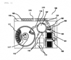
- FIG. 1 is a plan view of the automatic analyzer.
- the automatic analyzer 100 includes a rack 108, a rack transport line 115, a sample dispensing mechanism 116, an incubator (reaction disk) 107, a storage unit 106, a transport mechanism 105, a reaction container stirring mechanism 104, a disposal hole 102, a reagent disk 117, a reagent dispensing mechanism 110, a reaction liquid aspiration nozzle 113, a detection unit 114, and a control unit (not shown).
- a sample container 103 that contains a sample is set in the rack 108.
- the rack transport line 115 moves the sample container 103 set in the rack 108 to a sample dispensing position near the sample dispensing mechanism 116.
- the sample dispensing mechanism 116 has an arm that rotates and moves up and down and a nozzle that aspirates and discharges the sample.
- a sample dispensing tip can be attached to or detached from the tip of the nozzle.
- the sample dispensing mechanism 116 moves its nozzle down to the sample container 103 at the sample dispensing position and aspirates a prescribed amount of sample, then rotates the arm to discharge the sample into a reaction container 109 at a prescribed position over the incubator 107.
- a plurality of container holding holes in which a plurality of reaction containers 109 can be set are formed in a circumferential direction.
- the incubator 107 rotates to move each reaction container 109 to prescribed positions such as a reaction container set position, a reagent discharge position, a sample discharge position, and a reaction container disposal position.
- a plurality of reaction containers 109 and sample dispensing tips that are unused are set in the storage unit 106.
- the transport mechanism 105 can move in three directions, namely X axis, Y axis and Z axis directions, and transports the reaction container 109 and sample dispensing tip.
- the transport mechanism 105 transports an unused reaction container 109 to a container holding hole at a prescribed position of the incubator 107 and transports an unused sample dispensing tip to a sample dispensing tip mounting position 101.
- the transport mechanism 105 transports the reaction container 109 to a reaction container stirring mechanism 104 and transports the reaction container 109 and sample dispensing tip that have been used, to a disposal hole 102.
- the reaction container stirring mechanism 104 is a mechanism that mixes the sample in the reaction container 109 taken out of the incubator 107 and a reagent.
- the disposal hole 102 is a hole to dispose of the container 109 and sample dispensing tip that have been used.
- a plurality of reagent containers 111 are set in the reagent disk 117.
- a reagent disk cover 112 is provided over the reagent disk 117 and the inside of the reagent disk 117 is kept at a prescribed temperature.
- An opening portion is formed in part of the reagent disk cover 112.
- the reagent dispensing mechanism 110 has an arm that rotates and moves up and down and a nozzle that aspirates and discharges a reagent.
- the reagent dispensing mechanism 110 immerses the tip of the nozzle in the reagent in the reagent container 111 to aspirate the reagent and discharges the aspirated reagent into the reaction container 109.
- the reaction liquid aspiration nozzle 113 rotates and moves up and down to aspirate the reaction liquid mixed in the reaction container 109 on the incubator 107 and send it to the detection unit 114.
- the detection unit 114 detects a specific component contained in the reaction liquid aspirated by the reaction liquid aspiration nozzle 113.
- the control unit (not shown) controls operation of the whole automatic analyzer 100.
- the control unit receives input from an operator and outputs a control signal to various mechanisms and so on to control their operation.
- the transport mechanism 105 moves to above the storage unit 106, then moves down, grips an unused reaction container 109 and moves up. After that, the transport mechanism 105 moves to above a prescribed position of the incubator 107, then moves down and sets the reaction container 109 in a container holding hole. Again, the transport mechanism 105 moves to above the storage unit 106, moves down, grips an unused sample dispensing tip and moves up. After that, the transport mechanism 105 moves to above the sample dispensing tip mounting position 101 and moves down to set the sample dispensing tip at the sample dispensing tip mounting position 101. Then, the sample dispensing mechanism 116 moves to above the sample dispensing tip mounting position 101, then moves down and presses the sample dispensing tip into the tip of the nozzle to mount it there.
- the reagent dispensing mechanism 110 rotates and moves to above the opening portion of the reagent disk cover 112, then moves down, immerses the tip of the nozzle in the reagent in the reagent container 111 and aspirates a prescribed amount of reagent. Then, the reagent dispensing mechanism 110 moves up and rotates and moves to above a prescribed position of the incubator 107, and moves down to discharge the reagent into the reaction container 109.
- the sample dispensing mechanism 116 with the sample dispensing tip mounted thereon rotates and moves to above the sample container 103 placed in the rack 108, then moves down and aspirates a prescribed amount of sample in the sample container 103. After that, the sample dispensing mechanism 116 rotates and moves to the sample discharge position of the incubator 107, then moves down and discharges the sample into the reaction container 109 into which the reagent has been dispensed. After that, the sample dispensing mechanism 116 rotates and moves to above the disposal hole 102 and disposes of the used sample dispensing tip into the disposal hole 102.
- reaction container 109 into which the sample and reagent have been discharged is moved to a prescribed position by rotation of the incubator 107 and transported to the reaction container stirring mechanism 104 by the transport mechanism 105.
- the reaction container stirring mechanism 104 stirs and mixes the sample and reagent by applying rotating motion to the reaction container 109. After that, the reaction container 109 is moved back to the prescribed position of the incubator 107 by the transport mechanism 105.
- reaction liquid aspiration nozzle 113 moves to above the reaction container 109, then moves down and aspirates the reaction liquid in the reaction container 109.
- the reaction liquid aspirated by the reaction liquid aspiration nozzle 113 is analyzed by the detection unit 114.
- a fluorescence method, chemiluminescence method and electrochemiluminescence method are used as analysis methods for measuring the presence and concentration of an extremely small amount of the object of measurement in the reaction liquid (10 -14 mol or less) .
- an explanation is given of an example of using the electrochemiluminescence method in which the light emitted from the reaction liquid is detected when a voltage is applied to the reaction liquid.
- a luminescent reagent is bound to the object of measurement such as a hormone by antigen-antibody reaction to determine the quantity of emitted light derived from the luminescent reagent.
- the measurement is performed while the reaction liquid is made to flow in the flow cell.
- the detection unit 114 includes: a flow cell 209 into which the reaction liquid is introduced; a magnetic trap means that captures the magnetic particles contained in the reaction liquid; and a photomultiplier tube 211 that detects the light generated in the flow cell 209.
- the flow path inlet side of the flow cell 209 is connected to the reaction liquid aspiration nozzle 113 through a piping 205 and its flow path outlet side is connected to a syringe 204 that generates a pressure difference to aspirate the reaction liquid, etc. and a drain 203 to discharge the reaction liquid, etc.
- the flow path outlet side of the flow cell 209 is bifurcated midway by a flow path switching valve 201, into one path extending to the syringe 204 and the other path extending to the drain 203.
- the flow cell 209 is housed in a case 202 located under the photomultiplier tube 211 and fixed on a cell frame 210.
- the magnetic trap means includes a magnet for capturing magnetic particles 208, a magnet arm 207, and a magnet drive motor 206. By driving the magnet drive motor 206, the magnetic trap means rotates the magnet arm 207 to change the position of the magnet for capturing magnetic particles 208 to an operating position (position near the flow cell 209) or an escape position (position remoter from the flow cell 209).
- the photomultiplier tube 211 is a light detector that is disposed above the flow cell 209.
- the flow cell 209 is connected to a voltage applying means (not shown). As a voltage is applied by the voltage applying means, a luminous phenomenon occurs in the magnetic particles captured in the flow cell 209.
- the photomultiplier tube 211 measures the intensity of light generated in the flow cell 209.
- the flow path switching valve 201 is switched so that the flow path on the drain 203 side is closed and the flow path on the flow cell 209 side is open. Then, the syringe 204 is activated toward the aspiration side to aspirate the reaction liquid in the reaction container 109, and the reaction liquid in the reaction container 109 passes through the piping 205 and flows into the flow cell 209.
- the reaction liquid is a mixture of the sample containing the object of measurement and the reagent (reagent containing a luminescent label, and a reagent containing magnetic particles), which forms an immune complex.
- the magnet drive motor 206 is driven to rotate the magnet arm 207 90 degrees, so the magnet for capturing magnetic particles 208 at the tip of the magnet arm 207 comes to just below the flow cell 209 (moves to the operating position). Consequently, the magnetic particles in the reaction liquid passing through the flow cell 209 are magnetically captured by the flow cell 209.
- reaction liquid aspiration nozzle 113 moves to a container that contains an auxiliary liquid for luminescent reaction and with the nozzle 113 immersed in the auxiliary liquid for luminescent reaction, the syringe 204 is activated toward the aspiration side. Consequently, the auxiliary liquid for luminescent reaction flows into the flow cell 209 and while the immune complex remains magnetically captured, the residual reaction liquid in the flow cell 209 is substituted by the auxiliary liquid for luminescent reaction.
- the magnet drive motor 206 is driven in the opposite direction and the magnet arm 207 rotates backward 90 degrees, so the magnet for capturing magnetic particles 208 moves away from the flow cell 209 (moves to the escape position).
- the photomultiplier tube 211 measures the dark current output signal in the flow cell 209 through a light transmission window formed in the upper surface of the flow cell 209. After that, a voltage is applied to the inside of the flow cell 209 by the voltage applying means so that electrochemical luminescent reaction of the luminescent label contained in the immune complex is induced. At this time, the photomultiplier tube 211 measures the light intensity through the light transmission window and determines the quantity of the object of measurement contained in the immune complex.
- reaction liquid aspiration nozzle 113 moves to a container containing a cleaning liquid and with the nozzle 113 immersed in the cleaning liquid, the syringe 204 is activated toward the aspiration side. Consequently, the cleaning liquid flows into the piping 205 and flow cell 209, and the reaction liquid and auxiliary liquid for luminescent reaction that are remaining in the piping 205 and flow cell 209 are removed to clean the piping 205 and flow cell 209.
- the flow path switching valve 201 is switched to close the flow path on the flow cell 209 side and open the flow path on the drain 203 side. Then, the syringe is activated toward the discharge side, and the reaction liquid, auxiliary liquid for luminescent reaction and cleaning liquid that are remaining in the syringe 204 are discharged into the drain 203.
- FIG. 3 is a perspective view showing the appearance of the detection unit 114.
- the detection unit 114 incorporates the flow cell 209, photomultiplier tube 211 and so on.
- the photomultiplier tube 211 receives the very weak light generated by luminescent reaction of the luminescent label contained in the immune complex in the flow cell 209 under a low noise condition, and picks it up as an electric signal. Therefore, in order to block the external light as a main reason for the decline in the S/N ratio at the time of signal measurement by the photomultiplier tube 211, the housing 300 of the detection unit 114 and the lid 301 are made of a light-blocking material and has a hermetically sealed structure.
- the lid 301 is connected to the housing 300 by hinges 303, and tightening jigs 304 that fix the lid 301 in the closed state are provided as position fixing members on the lid 301. Therefore, when opening or closing the lid 301, work for installing and removing screws is not needed, so loading and unloading of the flow cell 200 can be carried out easily in a short time.
- a sealing member is provided all along the peripheral edge of the opening portion 302 of the housing 300, namely the front end of the side wall of the housing 300.
- the material of the sealing member is not limited as far as it is a material that has cushioning and heat-insulating properties, such as black soft rubber or soft polyurethane.
- the sealing member may be located on the back side of the lid 301 and at a position facing the front end of the side wall of the housing 300. Since the detection unit 114 has a sealing member like this, the sealability is improved and thus penetration of external light or temperature change due to inflow of external air can be prevented.
- the tightening jig 304 may be another type of fixing member such as a hook, as far as it can press the lid 301 against the sealing member between the housing 300 and lid 301 to fix the position of the lid 301.
- the tightening jig 304 may be located in the housing 300 so that its position changes with respect to the lid 301 from the housing 300 side for locking.
- an immune assay may be given by an immunoanalytical electrochemiluminescence method based on the electrochemiluminescence method that uses the magnetic trap means and photomultiplier tube 211.
- the fixing member should be made of a non-magnetic material and configured to tighten the lid 301 and housing 300 mechanically.
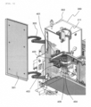
- FIG. 4 is a perspective view showing the internal structure of the detection unit 114 in a state in which the flow cell 209 is mounted.
- the detection unit 114 includes a photomultiplier tube 211, a board 401 disposed vertically below the photomultiplier tube 211, and a flow cell 209 disposed vertically below the board.
- the lower surface of the flow cell 209 is pressed vertically upward from below by a pressing member 402, so the flow cell 209 and photomultiplier tube 211 closely contact each other, thereby improving the light blocking effect in the area surrounded by the flow path in the flow cell 209 and the photomultiplier tube 211.
- the pressing member 402 presses the flow cell 209 at several spots, so the sealability of the flow cell 209 and the photomultiplier tube 211 is further improved. Since the flow cell 209 is fixed on the board 401 by the pressing member 402, the flow cell 209 can be loaded and unloaded more easily than when screws or the like are used to fix it.
- FIG. 5 is a cross-sectional perspective view of the flow cell 209.
- a recess portion 209a is formed in a circular shape on the inner circumferential side and a protrusion portion 209b is formed in a circumferential shape on its outer circumferential side.
- Two positioning holes are formed on the outer circumferential side of the protrusion portion 209b of the flow cell 209 at specific positions in the circumferential direction.
- FIG. 6 is a perspective view of the internal structure of the detection unit 114, showing a state before the flow cell 209 is loaded.
- a protrusion portion 404 is formed in a circular shape on the inner circumferential side and a recess portion 405 is formed in a circumferential shape on its outer circumferential side.
- a positioning pin 403 that extends vertically downward from a specific position in the circumferential direction is provided outside the recess portion 405. The positioning pin 403 is disposed at two target positions with respect to the center of the protrusion portion 404.
- the recess portion 209a of the flow cell 209 is fitted to the protrusion portion 404 of the board 401 and the protrusion portion 209b of the flow cell 209 is fitted to the recess portion 405 of the board 401. Then, the positioning holes of the flow cell 209 are inserted to the positioning pins 403 of the board 401 to fix the position of the flow cell 209 with respect to the board 401. After that, as shown in FIG. 4 , a plurality of pressing members 402 are pressed against the lower surface of the flow cell 209 so that the flow cell 209 is fixed on the board 401 in axial alignment with the photomultiplier tube 211.
- FIG. 7 is a front view showing the configuration of an interlocking mechanism 501 that interlocks operations of the two (left and right) pressing members 402.
- the interlocking mechanism 501 includes an operation knob 502, a connecting plate 503, and an arm 506. As the operator holds and slides the operation knob 502 horizontally in a prescribed direction, the pressing members 402 are moved simultaneously and symmetrically through the connecting plate 503 and arm 506 and the two pressing members 402 press the flow cell 209 simultaneously. Since the two pressing members 402 can be pressed or released simply by moving the operation knob 502, it is easy to load or unload the flow cell 209.
- the pressing member 402 has a pressing portion on the upper surface of its tip and the pressing portion presses the lower surface of the flow cell 209.
- the pressing member 402 should be made of a material excellent in abrasion resistance and slidability, as typified by polyacetal resin.
- the spring force of a pressing pressure spring 508 attached to a SUS shaft 505 that connects the arm 506 and pressing member 402 is used.
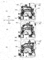
- FIG. 8 is a plan view showing a state in which the two (left and right) pressing members 402 press the flow cell 209 simultaneously.
- FIG. 8(1) shows a state in which the pressing members 402 are in the escape state
- FIG. 8(2) shows a state in which the pressing members 402 are moving for locking
- FIG. 8(3) shows a state in which locking motion by the pressing members 402 is completed.
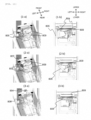
- FIG. 9 is a perspective view showing a state in which the two (left and right) pressing members 402 press the flow cell 209 simultaneously, as viewed from below.
- FIG. 9(1) shows a state in which the pressing members 402 are in the escape state
- FIG. 9(2) shows a state in which the pressing members 402 are moving for locking
- FIG. 9(3) shows a state in which locking motion by the pressing members 402 is completed.
- the flow cell 209 is attached from below the board 401 with the recess and protrusion portions fitted to each other on the contact surface, and the positioning pins 403 are inserted into the positioning holes of the flow cell 209.
- the process proceeds from the state as shown in FIG. 8(2) and FIG. 9(2) in which the movement for locking is under way, to the state as shown in FIG. 8(3) and FIG. 9(3) in which the lower surface of the flow cell 209 is pressed by the two pressing members 402 to lock the flow cell 209 completely.
- the pressing spring 508 pushes up the pressing member 402.
- the left pressing member 402 presses the left side with respect to the center of the flow cell 209 and the right pressing member 402 presses the right side with respect to the center of the flow cell 209.
- the flow cell 209 can be loaded and unloaded without using screws and without taking out the board 401.
- guide members 804 that guide the positioning hole of the flow cell 209 to the position of the positioning pin 403 of the board 401 are provided on the left and right of the detection unit 114. These guide members 804 are curved horizontally along the outer shape of the flow cell 209 to facilitate positioning of the flow cell 209.
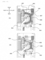
- FIG. 10 is a plan view showing a state in which the two (front and rear) pressing members 809 (leaf springs 805) press the flow cell 209 simultaneously.
- FIG. 10 (1) shows a state in which the pressing members 809 are in the escape state and
- FIG. 10(2) shows a state in which locking motion by the pressing members 809 is completed.
- FIG. 11 is a perspective view showing a state in which the front and rear pressing members 809 press the flow cell 209 simultaneously as viewed from below, and a front view of the pressing members 809 as viewed from the front.
- FIG. 11 (1-a) and FIG. 11 (1-b) show a state in which the pressing members 809 are in the escape state
- FIG. 11 (2-a) and FIG. 11 (2-b) show a state in which the pressing members 809 are moving for locking
- FIG. 11 (3-a) and FIG. 11 (3-b) show a state in which locking motion by the pressing members 809 is completed.
- the flow cell 209 is inserted from the front side of the board 401 below the board 401 along the guide members 804 and the positioning pin 403 of the board 401 is inserted into the positioning hole of the flow cell 209. Since the guide member 804 is to be in contact with the flow cell 209, in order to prevent chipping it is desirable that it should be made of a material excellent in abrasion resistance and slidabililty, as typified by polyacetal.
- the operation lever 803 is connected to the front leaf spring 805 through a rotating shaft 807 and the front leaf spring 805 and the rear leaf spring 805 are connected by a bearing portion 806, so the front and rear pressing members 809 are moved simultaneously by rotation of the operation lever 803.
- the spring force of the leaf spring 805 is used for the pressing force of the pressing member 809. Since the pressing member 809 is to be in contact with the flow cell 209, in order to prevent chipping it is desirable that it should be made of a material excellent in abrasion resistance and slidabililty, as typified by polyacetal.
- the front pressing member 809 presses the front side with respect to the center of the flow cell 209 and the rear pressing member 809 presses the rear side with respect to the center of the flow cell 209.
- the front and rear pressing members 809 press the flow cell 209 simultaneously, the imbalance between the pressing forces is suppressed and a positioning error is prevented, thereby contributing to improvement in the light blocking effect.
- the above embodiment has been described by taking as an example the detection unit 114 that is used for immune assay based on the electrochemiluminescence method.
- the hinge structure in this embodiment can be applied to a detection unit that is used in other types of analysis methods such as the fluorescence method and chemiluminescence method.
- the number of pressing members and their positions given here are merely one example and not limited to the above embodiment.
Landscapes
- Chemical & Material Sciences (AREA)
- Health & Medical Sciences (AREA)
- Physics & Mathematics (AREA)
- General Physics & Mathematics (AREA)
- Life Sciences & Earth Sciences (AREA)
- Analytical Chemistry (AREA)
- Biochemistry (AREA)
- General Health & Medical Sciences (AREA)
- Immunology (AREA)
- Pathology (AREA)
- Nuclear Medicine, Radiotherapy & Molecular Imaging (AREA)
- Engineering & Computer Science (AREA)
- Chemical Kinetics & Catalysis (AREA)
- Plasma & Fusion (AREA)
- Automatic Analysis And Handling Materials Therefor (AREA)
- Investigating Or Analysing Materials By The Use Of Chemical Reactions (AREA)
Abstract
Description
- The present invention relates to an automatic analyzer.
- The automatic analyzer is a device that automatically analyzes a sample such as blood or urine. As an immunoanalytical method for the detection unit of an automatic analyzer, the method in which a reaction liquid containing a sample is introduced into a flow cell and emitted light is detected by a light detector is known. This type of detection method that uses a flow cell is disclosed, for example, in
Patent Literature 1. - Generally, the flow cell loaded in a conventional detection unit is fixed on the board using screws to prevent it from being out of alignment with a photomultiplier tube. By fixing the flow cell on the board using screws in this way, the light blocking effect for the area surrounded by the flow path in the flow cell and the photomultiplier tube is improved, thereby suppressing the decline in the S/N ratio at the time of signal measurement by the photomultiplier tube.
- Patent Literature 1:
Japanese Unexamined Patent Application Publication No. 2014-149305 - However, when the flow cell is fixed on the board with screws, it is necessary to install or remove the screws each time the flow cell is loaded or unloaded. This results in a low working efficiency.
- The object of the present invention is to provide an automatic analyzer that improves the working efficiency in loading or unloading a flow cell.
- In order to solve the above problem, according to the present invention, an automatic analyzer includes: a photomultiplier tube; a board disposed vertically below the photomultiplier tube; and a flow cell disposed vertically below the board, in which a lower surface of the board has a protrusion portion and/or a recess portion, and an upper surface of the flow cell has a recess portion and/or a protrusion portion, and the automatic analyzer includes a pressing member configured to press the flow cell vertically upward from below in a state in which the recess portion and/or the protrusion portion of the flow cell is fitted to the protrusion portion and/or the recess portion of the board.
- According to the present disclosure, it is possible to provide an automatic analyzer that improves the working efficiency in loading or unloading a flow cell.
-
- [
FIG. 1] FIG. 1 is a plan view of an automatic analyzer. - [
FIG. 2] FIG. 2 is a diagram showing a flow path configuration of a detection unit. - [
FIG. 3] FIG. 3 is a perspective view showing an appearance of the detection unit. - [
FIG. 4] FIG. 4 is a perspective view showing an internal structure of the detection unit (a state in which a flow cell is mounted). - [
FIG. 5] FIG. 5 is a cross-sectional perspective view of the flow cell. - [
FIG. 6] FIG. 6 is a perspective view showing an internal structure of the detection unit (a state before mounting the flow cell). - [
FIG. 7] FIG. 7 is a front view showing a configuration of an interlocking mechanism that interlocks operations of a pressing member. - [
FIG. 8] FIG. 8 is a plan view showing a state in which left and right pressing members simultaneously press the flow cell. - [
FIG. 9] FIG. 9 is a perspective view as viewed from below showing a state in which the left and right pressing members simultaneously press the flow cell. - [
FIG. 10] FIG. 10 is a plan view showing a state in which front and rear pressing members simultaneously press the flow cell. - [
FIG. 11] FIG. 11 is a perspective view as viewed from below and a front view as viewed from the front showing a state in which the front and rear pressing members simultaneously press the flow cell. - Hereinafter, an embodiment of the present invention will be described referring to drawings.
- First, the general configuration of an automatic analyzer will be described referring to
FIG. 1. FIG. 1 is a plan view of the automatic analyzer. - The
automatic analyzer 100 includes arack 108, arack transport line 115, asample dispensing mechanism 116, an incubator (reaction disk) 107, astorage unit 106, atransport mechanism 105, a reactioncontainer stirring mechanism 104, adisposal hole 102, areagent disk 117, areagent dispensing mechanism 110, a reactionliquid aspiration nozzle 113, adetection unit 114, and a control unit (not shown). - A
sample container 103 that contains a sample is set in therack 108. - The
rack transport line 115 moves thesample container 103 set in therack 108 to a sample dispensing position near thesample dispensing mechanism 116. - The
sample dispensing mechanism 116 has an arm that rotates and moves up and down and a nozzle that aspirates and discharges the sample. A sample dispensing tip can be attached to or detached from the tip of the nozzle. Thesample dispensing mechanism 116 moves its nozzle down to thesample container 103 at the sample dispensing position and aspirates a prescribed amount of sample, then rotates the arm to discharge the sample into areaction container 109 at a prescribed position over theincubator 107. - In the
incubator 107, a plurality of container holding holes in which a plurality ofreaction containers 109 can be set are formed in a circumferential direction. Theincubator 107 rotates to move eachreaction container 109 to prescribed positions such as a reaction container set position, a reagent discharge position, a sample discharge position, and a reaction container disposal position. - A plurality of
reaction containers 109 and sample dispensing tips that are unused are set in thestorage unit 106. - The
transport mechanism 105 can move in three directions, namely X axis, Y axis and Z axis directions, and transports thereaction container 109 and sample dispensing tip. For example, thetransport mechanism 105 transports anunused reaction container 109 to a container holding hole at a prescribed position of theincubator 107 and transports an unused sample dispensing tip to a sample dispensingtip mounting position 101. Also, for example, thetransport mechanism 105 transports thereaction container 109 to a reactioncontainer stirring mechanism 104 and transports thereaction container 109 and sample dispensing tip that have been used, to adisposal hole 102. - The reaction
container stirring mechanism 104 is a mechanism that mixes the sample in thereaction container 109 taken out of theincubator 107 and a reagent. - The
disposal hole 102 is a hole to dispose of thecontainer 109 and sample dispensing tip that have been used. - A plurality of
reagent containers 111 are set in thereagent disk 117. Areagent disk cover 112 is provided over thereagent disk 117 and the inside of thereagent disk 117 is kept at a prescribed temperature. An opening portion is formed in part of thereagent disk cover 112. - The
reagent dispensing mechanism 110 has an arm that rotates and moves up and down and a nozzle that aspirates and discharges a reagent. Thereagent dispensing mechanism 110 immerses the tip of the nozzle in the reagent in thereagent container 111 to aspirate the reagent and discharges the aspirated reagent into thereaction container 109. - The reaction
liquid aspiration nozzle 113 rotates and moves up and down to aspirate the reaction liquid mixed in thereaction container 109 on theincubator 107 and send it to thedetection unit 114. - The
detection unit 114 detects a specific component contained in the reaction liquid aspirated by the reactionliquid aspiration nozzle 113. - The control unit (not shown) controls operation of the whole
automatic analyzer 100. The control unit receives input from an operator and outputs a control signal to various mechanisms and so on to control their operation. - Next, an explanation will be given of operation of the
automatic analyzer 100. - First, the
transport mechanism 105 moves to above thestorage unit 106, then moves down, grips anunused reaction container 109 and moves up. After that, thetransport mechanism 105 moves to above a prescribed position of theincubator 107, then moves down and sets thereaction container 109 in a container holding hole. Again, thetransport mechanism 105 moves to above thestorage unit 106, moves down, grips an unused sample dispensing tip and moves up. After that, thetransport mechanism 105 moves to above the sample dispensingtip mounting position 101 and moves down to set the sample dispensing tip at the sample dispensingtip mounting position 101. Then, thesample dispensing mechanism 116 moves to above the sample dispensingtip mounting position 101, then moves down and presses the sample dispensing tip into the tip of the nozzle to mount it there. - The
reagent dispensing mechanism 110 rotates and moves to above the opening portion of thereagent disk cover 112, then moves down, immerses the tip of the nozzle in the reagent in thereagent container 111 and aspirates a prescribed amount of reagent. Then, thereagent dispensing mechanism 110 moves up and rotates and moves to above a prescribed position of theincubator 107, and moves down to discharge the reagent into thereaction container 109. - Also, the
sample dispensing mechanism 116 with the sample dispensing tip mounted thereon rotates and moves to above thesample container 103 placed in therack 108, then moves down and aspirates a prescribed amount of sample in thesample container 103. After that, thesample dispensing mechanism 116 rotates and moves to the sample discharge position of theincubator 107, then moves down and discharges the sample into thereaction container 109 into which the reagent has been dispensed. After that, thesample dispensing mechanism 116 rotates and moves to above thedisposal hole 102 and disposes of the used sample dispensing tip into thedisposal hole 102. - After that, the
reaction container 109 into which the sample and reagent have been discharged is moved to a prescribed position by rotation of theincubator 107 and transported to the reactioncontainer stirring mechanism 104 by thetransport mechanism 105. The reactioncontainer stirring mechanism 104 stirs and mixes the sample and reagent by applying rotating motion to thereaction container 109. After that, thereaction container 109 is moved back to the prescribed position of theincubator 107 by thetransport mechanism 105. - Next, when a given reaction time has elapsed at the prescribed position, the reaction
liquid aspiration nozzle 113 moves to above thereaction container 109, then moves down and aspirates the reaction liquid in thereaction container 109. The reaction liquid aspirated by the reactionliquid aspiration nozzle 113 is analyzed by thedetection unit 114. - Hereinafter, the configuration of the
detection unit 114 will be described referring toFIG. 2 . In the immunoanalytical field, a fluorescence method, chemiluminescence method and electrochemiluminescence method are used as analysis methods for measuring the presence and concentration of an extremely small amount of the object of measurement in the reaction liquid (10-14 mol or less) . For this embodiment, an explanation is given of an example of using the electrochemiluminescence method in which the light emitted from the reaction liquid is detected when a voltage is applied to the reaction liquid. - In the electrochemiluminescence method, a luminescent reagent is bound to the object of measurement such as a hormone by antigen-antibody reaction to determine the quantity of emitted light derived from the luminescent reagent. The measurement is performed while the reaction liquid is made to flow in the flow cell.
- The
detection unit 114 includes: aflow cell 209 into which the reaction liquid is introduced; a magnetic trap means that captures the magnetic particles contained in the reaction liquid; and aphotomultiplier tube 211 that detects the light generated in theflow cell 209. - As shown in
FIG. 2 , the flow path inlet side of theflow cell 209 is connected to the reactionliquid aspiration nozzle 113 through apiping 205 and its flow path outlet side is connected to asyringe 204 that generates a pressure difference to aspirate the reaction liquid, etc. and adrain 203 to discharge the reaction liquid, etc. The flow path outlet side of theflow cell 209 is bifurcated midway by a flowpath switching valve 201, into one path extending to thesyringe 204 and the other path extending to thedrain 203. Theflow cell 209 is housed in acase 202 located under thephotomultiplier tube 211 and fixed on acell frame 210. - The magnetic trap means includes a magnet for capturing
magnetic particles 208, amagnet arm 207, and amagnet drive motor 206. By driving themagnet drive motor 206, the magnetic trap means rotates themagnet arm 207 to change the position of the magnet for capturingmagnetic particles 208 to an operating position (position near the flow cell 209) or an escape position (position remoter from the flow cell 209). - The
photomultiplier tube 211 is a light detector that is disposed above theflow cell 209. Theflow cell 209 is connected to a voltage applying means (not shown). As a voltage is applied by the voltage applying means, a luminous phenomenon occurs in the magnetic particles captured in theflow cell 209. Thephotomultiplier tube 211 measures the intensity of light generated in theflow cell 209. - Next, an explanation will be given of the method for measuring the light intensity in the
detection unit 114. - First, with the reaction
liquid aspiration nozzle 113 immersed in the reaction liquid in thereaction container 109, the flowpath switching valve 201 is switched so that the flow path on thedrain 203 side is closed and the flow path on theflow cell 209 side is open. Then, thesyringe 204 is activated toward the aspiration side to aspirate the reaction liquid in thereaction container 109, and the reaction liquid in thereaction container 109 passes through the piping 205 and flows into theflow cell 209. The reaction liquid is a mixture of the sample containing the object of measurement and the reagent (reagent containing a luminescent label, and a reagent containing magnetic particles), which forms an immune complex. - At this time, the
magnet drive motor 206 is driven to rotate themagnet arm 207 90 degrees, so the magnet for capturingmagnetic particles 208 at the tip of themagnet arm 207 comes to just below the flow cell 209 (moves to the operating position). Consequently, the magnetic particles in the reaction liquid passing through theflow cell 209 are magnetically captured by theflow cell 209. - After that, the reaction
liquid aspiration nozzle 113 moves to a container that contains an auxiliary liquid for luminescent reaction and with thenozzle 113 immersed in the auxiliary liquid for luminescent reaction, thesyringe 204 is activated toward the aspiration side. Consequently, the auxiliary liquid for luminescent reaction flows into theflow cell 209 and while the immune complex remains magnetically captured, the residual reaction liquid in theflow cell 209 is substituted by the auxiliary liquid for luminescent reaction. - Then, after the
syringe 204 stops moving, themagnet drive motor 206 is driven in the opposite direction and themagnet arm 207 rotates backward 90 degrees, so the magnet for capturingmagnetic particles 208 moves away from the flow cell 209 (moves to the escape position). - Then, the
photomultiplier tube 211 measures the dark current output signal in theflow cell 209 through a light transmission window formed in the upper surface of theflow cell 209. After that, a voltage is applied to the inside of theflow cell 209 by the voltage applying means so that electrochemical luminescent reaction of the luminescent label contained in the immune complex is induced. At this time, thephotomultiplier tube 211 measures the light intensity through the light transmission window and determines the quantity of the object of measurement contained in the immune complex. - After measurement of the light intensity, the reaction
liquid aspiration nozzle 113 moves to a container containing a cleaning liquid and with thenozzle 113 immersed in the cleaning liquid, thesyringe 204 is activated toward the aspiration side. Consequently, the cleaning liquid flows into the piping 205 and flowcell 209, and the reaction liquid and auxiliary liquid for luminescent reaction that are remaining in thepiping 205 and flowcell 209 are removed to clean the piping 205 and flowcell 209. - Lastly, the flow
path switching valve 201 is switched to close the flow path on theflow cell 209 side and open the flow path on thedrain 203 side. Then, the syringe is activated toward the discharge side, and the reaction liquid, auxiliary liquid for luminescent reaction and cleaning liquid that are remaining in thesyringe 204 are discharged into thedrain 203. - By carrying out the above steps repeatedly, analysis is made on a plurality of samples for a plurality of analysis items.
-
FIG. 3 is a perspective view showing the appearance of thedetection unit 114. Thedetection unit 114 incorporates theflow cell 209,photomultiplier tube 211 and so on. In an immune assay based on the electrochemiluminescence method, thephotomultiplier tube 211 receives the very weak light generated by luminescent reaction of the luminescent label contained in the immune complex in theflow cell 209 under a low noise condition, and picks it up as an electric signal. Therefore, in order to block the external light as a main reason for the decline in the S/N ratio at the time of signal measurement by thephotomultiplier tube 211, thehousing 300 of thedetection unit 114 and thelid 301 are made of a light-blocking material and has a hermetically sealed structure. - The
lid 301 is connected to thehousing 300 byhinges 303, and tighteningjigs 304 that fix thelid 301 in the closed state are provided as position fixing members on thelid 301. Therefore, when opening or closing thelid 301, work for installing and removing screws is not needed, so loading and unloading of the flow cell 200 can be carried out easily in a short time. - In addition, a sealing member is provided all along the peripheral edge of the
opening portion 302 of thehousing 300, namely the front end of the side wall of thehousing 300. The material of the sealing member is not limited as far as it is a material that has cushioning and heat-insulating properties, such as black soft rubber or soft polyurethane. The sealing member may be located on the back side of thelid 301 and at a position facing the front end of the side wall of thehousing 300. Since thedetection unit 114 has a sealing member like this, the sealability is improved and thus penetration of external light or temperature change due to inflow of external air can be prevented. - The tightening
jig 304 may be another type of fixing member such as a hook, as far as it can press thelid 301 against the sealing member between thehousing 300 andlid 301 to fix the position of thelid 301. Also, the tighteningjig 304 may be located in thehousing 300 so that its position changes with respect to thelid 301 from thehousing 300 side for locking. However, if it is structured to fix thelid 301 in the closed state by a magnetic force, an immune assay may be given by an immunoanalytical electrochemiluminescence method based on the electrochemiluminescence method that uses the magnetic trap means andphotomultiplier tube 211. For this reason, it is desirable that the fixing member should be made of a non-magnetic material and configured to tighten thelid 301 andhousing 300 mechanically. -
FIG. 4 is a perspective view showing the internal structure of thedetection unit 114 in a state in which theflow cell 209 is mounted. As shown inFIG. 4 , thedetection unit 114 includes aphotomultiplier tube 211, aboard 401 disposed vertically below thephotomultiplier tube 211, and aflow cell 209 disposed vertically below the board. In addition, the lower surface of theflow cell 209 is pressed vertically upward from below by a pressingmember 402, so theflow cell 209 andphotomultiplier tube 211 closely contact each other, thereby improving the light blocking effect in the area surrounded by the flow path in theflow cell 209 and thephotomultiplier tube 211. Particularly, the pressingmember 402 presses theflow cell 209 at several spots, so the sealability of theflow cell 209 and thephotomultiplier tube 211 is further improved. Since theflow cell 209 is fixed on theboard 401 by the pressingmember 402, theflow cell 209 can be loaded and unloaded more easily than when screws or the like are used to fix it. -
FIG. 5 is a cross-sectional perspective view of theflow cell 209. As shown inFIG. 5 , on the upper surface of theflow cell 209, arecess portion 209a is formed in a circular shape on the inner circumferential side and aprotrusion portion 209b is formed in a circumferential shape on its outer circumferential side. Two positioning holes are formed on the outer circumferential side of theprotrusion portion 209b of theflow cell 209 at specific positions in the circumferential direction. -
FIG. 6 is a perspective view of the internal structure of thedetection unit 114, showing a state before theflow cell 209 is loaded. As shown inFIG. 6 , on the lower surface of theboard 401, aprotrusion portion 404 is formed in a circular shape on the inner circumferential side and arecess portion 405 is formed in a circumferential shape on its outer circumferential side. In addition, on the lower surface of theboard 401, apositioning pin 403 that extends vertically downward from a specific position in the circumferential direction is provided outside therecess portion 405. Thepositioning pin 403 is disposed at two target positions with respect to the center of theprotrusion portion 404. - When attaching the
flow cell 209 to theboard 401, first therecess portion 209a of theflow cell 209 is fitted to theprotrusion portion 404 of theboard 401 and theprotrusion portion 209b of theflow cell 209 is fitted to therecess portion 405 of theboard 401. Then, the positioning holes of theflow cell 209 are inserted to the positioning pins 403 of theboard 401 to fix the position of theflow cell 209 with respect to theboard 401. After that, as shown inFIG. 4 , a plurality of pressingmembers 402 are pressed against the lower surface of theflow cell 209 so that theflow cell 209 is fixed on theboard 401 in axial alignment with thephotomultiplier tube 211. -
FIG. 7 is a front view showing the configuration of aninterlocking mechanism 501 that interlocks operations of the two (left and right) pressingmembers 402. Theinterlocking mechanism 501 includes anoperation knob 502, a connectingplate 503, and anarm 506. As the operator holds and slides theoperation knob 502 horizontally in a prescribed direction, thepressing members 402 are moved simultaneously and symmetrically through the connectingplate 503 andarm 506 and the twopressing members 402 press theflow cell 209 simultaneously. Since the twopressing members 402 can be pressed or released simply by moving theoperation knob 502, it is easy to load or unload theflow cell 209. - The pressing
member 402 has a pressing portion on the upper surface of its tip and the pressing portion presses the lower surface of theflow cell 209. In order to suppress scratching called chipping on theflow cell 209 when it is pressed, it is desirable that thepressing member 402 should be made of a material excellent in abrasion resistance and slidability, as typified by polyacetal resin. For the pressing force of thepressing member 402, the spring force of a pressing pressure spring 508 attached to aSUS shaft 505 that connects thearm 506 and pressingmember 402 is used. - Next, how the pressing
member 402 locks theflow cell 209 will be concretely explained. -
FIG. 8 is a plan view showing a state in which the two (left and right) pressingmembers 402 press theflow cell 209 simultaneously.FIG. 8(1) shows a state in which thepressing members 402 are in the escape state,FIG. 8(2) shows a state in which thepressing members 402 are moving for locking, andFIG. 8(3) shows a state in which locking motion by thepressing members 402 is completed. -
FIG. 9 is a perspective view showing a state in which the two (left and right) pressingmembers 402 press theflow cell 209 simultaneously, as viewed from below.FIG. 9(1) shows a state in which thepressing members 402 are in the escape state,FIG. 9(2) shows a state in which thepressing members 402 are moving for locking, andFIG. 9(3) shows a state in which locking motion by thepressing members 402 is completed. - First, when the
pressing members 402 are in the escape state as shown inFIG. 8(1) andFIG. 9(1) , theflow cell 209 is attached from below theboard 401 with the recess and protrusion portions fitted to each other on the contact surface, and the positioning pins 403 are inserted into the positioning holes of theflow cell 209. - Then, as the
operation knob 502 is slid to the right, the process proceeds from the state as shown inFIG. 8(2) andFIG. 9(2) in which the movement for locking is under way, to the state as shown inFIG. 8(3) andFIG. 9(3) in which the lower surface of theflow cell 209 is pressed by the twopressing members 402 to lock theflow cell 209 completely. As theoperation knob 502 is slid to the right horizontally, the pressing spring 508 pushes up thepressing member 402. At this time, theleft pressing member 402 presses the left side with respect to the center of theflow cell 209 and theright pressing member 402 presses the right side with respect to the center of theflow cell 209. This suppresses the imbalance between the left and right pressing forces on theflow cell 209, thereby improving the light blocking effect for the area surrounded by the flow path in theflow cell 209 and thephotomultiplier tube 211. Furthermore, since the left and right pressingmembers 402 press theflow cell 209 simultaneously, the imbalance between the pressing forces is suppressed and a positioning error is prevented, thereby contributing to improvement in the light blocking effect. - As explained above, according to this embodiment, the
flow cell 209 can be loaded and unloaded without using screws and without taking out theboard 401. - Next, a variation of the embodiment will be described referring to
FIG. 10 andFIG. 11 . In the variation, guidemembers 804 that guide the positioning hole of theflow cell 209 to the position of thepositioning pin 403 of theboard 401 are provided on the left and right of thedetection unit 114. Theseguide members 804 are curved horizontally along the outer shape of theflow cell 209 to facilitate positioning of theflow cell 209. - Next, how
pressing members 809 according to the variation lock theflow cell 209 will be concretely explained. -
FIG. 10 is a plan view showing a state in which the two (front and rear) pressing members 809 (leaf springs 805) press theflow cell 209 simultaneously.FIG. 10 (1) shows a state in which thepressing members 809 are in the escape state andFIG. 10(2) shows a state in which locking motion by thepressing members 809 is completed. -
FIG. 11 is a perspective view showing a state in which the front and rear pressingmembers 809 press theflow cell 209 simultaneously as viewed from below, and a front view of thepressing members 809 as viewed from the front.FIG. 11 (1-a) andFIG. 11 (1-b) show a state in which thepressing members 809 are in the escape state,FIG. 11 (2-a) andFIG. 11 (2-b) show a state in which thepressing members 809 are moving for locking, andFIG. 11 (3-a) andFIG. 11 (3-b) show a state in which locking motion by thepressing members 809 is completed. - First, in the escape state as shown in
FIG. 10(1) ,FIG. 11 (1-a) andFIG. 11 (1-b), theflow cell 209 is inserted from the front side of theboard 401 below theboard 401 along theguide members 804 and thepositioning pin 403 of theboard 401 is inserted into the positioning hole of theflow cell 209. Since theguide member 804 is to be in contact with theflow cell 209, in order to prevent chipping it is desirable that it should be made of a material excellent in abrasion resistance and slidabililty, as typified by polyacetal. - After that, as an
operation lever 803 of the interlocking mechanism to interlock the movements of the two (front and rear) pressingmembers 809 is rotated, the process proceeds from the state as shown inFIG. 11 (2-a) andFIG. 11 (2-b) in which movement for locking is under way, to the state as shown inFIG. 10(2) ,FIG. 11 (3-a) andFIG. 11 (3-b) in which the lower surface of theflow cell 209 is pressed by the twopressing members 809 to lock theflow cell 209 completely. Furthermore, if it is known in advance that theflow cell 209 will remain loaded for a long time, it can be fixed more stably by fixing it at afixed position 904 using a screw after completion of its locking, as shown inFIG. 11 (3-a). - Here, the
operation lever 803 is connected to thefront leaf spring 805 through arotating shaft 807 and thefront leaf spring 805 and therear leaf spring 805 are connected by a bearingportion 806, so the front and rear pressingmembers 809 are moved simultaneously by rotation of theoperation lever 803. The spring force of theleaf spring 805 is used for the pressing force of thepressing member 809. Since thepressing member 809 is to be in contact with theflow cell 209, in order to prevent chipping it is desirable that it should be made of a material excellent in abrasion resistance and slidabililty, as typified by polyacetal. - According to the variation, the
front pressing member 809 presses the front side with respect to the center of theflow cell 209 and the rear pressingmember 809 presses the rear side with respect to the center of theflow cell 209. This suppresses the imbalance between the front and rear pressing forces, thereby improving the light blocking effect for the area surrounded by the flow path in theflow cell 209 and thephotomultiplier tube 211. Furthermore, since the front and rear pressingmembers 809 press theflow cell 209 simultaneously, the imbalance between the pressing forces is suppressed and a positioning error is prevented, thereby contributing to improvement in the light blocking effect. - The above embodiment has been described by taking as an example the
detection unit 114 that is used for immune assay based on the electrochemiluminescence method. The hinge structure in this embodiment can be applied to a detection unit that is used in other types of analysis methods such as the fluorescence method and chemiluminescence method. The number of pressing members and their positions given here are merely one example and not limited to the above embodiment. -
- 100: automatic analyzer
- 101: sample dispensing tip mounting position
- 102: disposal hole
- 103: sample container
- 104: reaction container stirring mechanism
- 105: transport mechanism
- 106: storage unit
- 107: incubator
- 108: rack
- 109: reaction container
- 110: reagent dispensing mechanism
- 111: reagent container
- 112: reagent disk cover
- 113: reaction liquid suction nozzle
- 114: detection unit
- 115: rack transport line
- 116: sample dispensing mechanism
- 117: reagent disk
- 201: flow path switching valve
- 202: case
- 203: drain
- 204: syringe
- 205: piping
- 206: magnet drive motor
- 207: magnet arm
- 208: magnet for capturing magnetic particles
- 209: flow cell
- 209a: recess portion
- 209b: protrusion portion
- 211: photomultiplier tube
- 301: lid
- 302: opening portion
- 303: hinge
- 304: tightening jig
- 401: board
- 402: pressing member
- 403: positioning pin
- 404: protrusion portion
- 405: recess portion
- 501: interlocking mechanism
- 502: operation knob
- 503: connecting plate
- 504: pressing spring
- 505: SUS shaft
- 506: arm
- 803: operation lever
- 804: guide member
- 805: leaf spring
- 806: bearing portion
- 807: rotating shaft
- 809: pressing member
- 904: fixed position
Claims (6)
- An automatic analyzer, comprising:a photomultiplier tube;a board disposed vertically below the photomultiplier tube; anda flow cell disposed vertically below the board, whereina lower surface of the board has a protrusion portion and/or a recess portion, and an upper surface of the flow cell has a recess portion and/or a protrusion portion, andthe automatic analyzer comprises a pressing member configured to press the flow cell vertically upward from below in a state in which the recess portion and/or the protrusion portion of the flow cell is fitted to the protrusion portion and/or the recess portion of the board.
- The automatic analyzer according to claim 1, wherein
the pressing member is configured to press the flow cell at a plurality of places. - The automatic analyzer according to claim 1, wherein
the pressing member is configured to press one side and the other side with respect to a center of the flow cell. - The automatic analyzer according to claim 1, further comprising:a plurality of the pressing members; andan interlocking mechanism configured to interlock operations of the plurality of pressing members, whereinthe plurality of pressing members are configured to simultaneously press the flow cell by the interlocking mechanism.
- The automatic analyzer according to claim 1, whereinthe recess portion and/or the protrusion portion of the flow cell and the protrusion portion and/or the recess portion of the board are formed in circumferential shapes,the board includes a positioning pin extending vertically downward from a specific position in a circumferential direction, andthe flow cell has a positioning hole into which the positioning pin is to be inserted at a specific position in a circumferential direction.
- The automatic analyzer according to claim 5, wherein
a guide member configured to guide the positioning hole of the flow cell to a position of the positioning pin of the board is formed in a horizontal direction.
Applications Claiming Priority (2)
| Application Number | Priority Date | Filing Date | Title |
|---|---|---|---|
| JP2020069652 | 2020-04-08 | ||
| PCT/JP2021/007264 WO2021205771A1 (en) | 2020-04-08 | 2021-02-26 | Automatic analysis device |
Publications (3)
| Publication Number | Publication Date |
|---|---|
| EP4134678A1 true EP4134678A1 (en) | 2023-02-15 |
| EP4134678A4 EP4134678A4 (en) | 2024-05-01 |
| EP4134678B1 EP4134678B1 (en) | 2025-01-08 |
Family
ID=78023331
Family Applications (1)
| Application Number | Title | Priority Date | Filing Date |
|---|---|---|---|
| EP21785093.2A Active EP4134678B1 (en) | 2020-04-08 | 2021-02-26 | Automatic analysis device |
Country Status (5)
| Country | Link |
|---|---|
| US (1) | US12578351B2 (en) |
| EP (1) | EP4134678B1 (en) |
| JP (1) | JP7310013B2 (en) |
| CN (1) | CN115315629B (en) |
| WO (1) | WO2021205771A1 (en) |
Families Citing this family (1)
| Publication number | Priority date | Publication date | Assignee | Title |
|---|---|---|---|---|
| CN115184628B (en) * | 2021-11-29 | 2024-01-23 | 南京诺唯赞医疗科技有限公司 | Automatic card throwing mechanism and fluorescence immunoassay appearance |
Family Cites Families (21)
| Publication number | Priority date | Publication date | Assignee | Title |
|---|---|---|---|---|
| US5089424A (en) * | 1988-06-14 | 1992-02-18 | Abbott Laboratories | Method and apparatus for heterogeneous chemiluminescence assay |
| AT391030B (en) | 1988-12-01 | 1990-08-10 | Avl Verbrennungskraft Messtech | DEVICE FOR MEASURING CHEMICAL AND PHYSICAL PARAMETERS OF A LIQUID OR GASEOUS MEDIUM |
| JP3428746B2 (en) * | 1994-11-11 | 2003-07-22 | ロッシュ ディアグノスティクス ゲゼルシャフト ミット ベシュレンクテル ハフツング | Immunoassay method and analyzer |
| US5993740A (en) * | 1995-01-20 | 1999-11-30 | Hitachi, Ltd. | Immunoassay method and analyzer using magnetic particles |
| US8557598B2 (en) * | 2005-03-17 | 2013-10-15 | Sysmex Corporation | Method for measuring blood sample and apparatus thereof |
| JP5026851B2 (en) * | 2007-04-23 | 2012-09-19 | 株式会社日立製作所 | Chemiluminescence detector |
| US20090139311A1 (en) | 2007-10-05 | 2009-06-04 | Applied Biosystems Inc. | Biological Analysis Systems, Devices, and Methods |
| JP5524698B2 (en) | 2010-04-27 | 2014-06-18 | 株式会社日立ハイテクノロジーズ | Automatic analyzer |
| US20120119101A1 (en) * | 2010-11-12 | 2012-05-17 | Endress + Hauser Conducta Gesellschaft Fur Mess-Und Regeltechnik Mbh + Co. Kg | Miniature UV sensor utilizing a disposable flow cell |
| US8951781B2 (en) * | 2011-01-10 | 2015-02-10 | Illumina, Inc. | Systems, methods, and apparatuses to image a sample for biological or chemical analysis |
| FR2973720B1 (en) * | 2011-04-08 | 2016-02-26 | Commissariat Energie Atomique | DEVICE FOR CONNECTING A MICROFLUIDIC CARD |
| JP6239243B2 (en) | 2013-02-08 | 2017-11-29 | エフ.ホフマン−ラ ロシュ アーゲーF. Hoffmann−La Roche Aktiengesellschaft | Automatic analyzer |
| JP6178161B2 (en) * | 2013-08-21 | 2017-08-09 | 株式会社日立ハイテクノロジーズ | Flow cell fixing device and nucleic acid analyzer |
| JP5805259B2 (en) | 2014-04-10 | 2015-11-04 | 株式会社日立ハイテクノロジーズ | Automatic analyzer |
| CN105806828B (en) | 2015-10-29 | 2019-05-14 | 北京联众泰克科技有限公司 | A kind of Electrogenerated chemiluminescent immunoassay system and its flow cell component |
| JP2019508669A (en) * | 2016-01-11 | 2019-03-28 | イラミーナ インコーポレーテッド | Microfluorometer, fluid system, and detection device having a flow cell latch clamp module |
| US9976946B2 (en) | 2016-04-21 | 2018-05-22 | Instrumentation Laboratory Company | Optical flow cell and test head apparatus |
| CN206292169U (en) | 2016-12-30 | 2017-06-30 | 国家海洋局第二海洋研究所 | A kind of Portable fluorescence detector that can be applied to extra large underwater trace ammonium nitrogen analysis |
| TWI738328B (en) * | 2017-09-28 | 2021-09-01 | 美商伊路米納有限公司 | Fluid dispenser assembly and method for dispensing fluid into a fluid cartridge |
| US11041797B2 (en) * | 2017-12-23 | 2021-06-22 | Lumacyte, LLC | Microfluidic chip device for optical force measurements and cell imaging using microfluidic chip configuration and dynamics |
| CN209946182U (en) * | 2019-05-17 | 2020-01-14 | 吉林欧伊尔环保科技发展有限公司 | Sample cell moving platform structure for analyzer |
-
2021
- 2021-02-26 US US17/915,325 patent/US12578351B2/en active Active
- 2021-02-26 CN CN202180023108.0A patent/CN115315629B/en active Active
- 2021-02-26 EP EP21785093.2A patent/EP4134678B1/en active Active
- 2021-02-26 JP JP2022514331A patent/JP7310013B2/en active Active
- 2021-02-26 WO PCT/JP2021/007264 patent/WO2021205771A1/en not_active Ceased
Also Published As
| Publication number | Publication date |
|---|---|
| US12578351B2 (en) | 2026-03-17 |
| JP7310013B2 (en) | 2023-07-18 |
| JPWO2021205771A1 (en) | 2021-10-14 |
| EP4134678B1 (en) | 2025-01-08 |
| CN115315629B (en) | 2025-11-25 |
| EP4134678A4 (en) | 2024-05-01 |
| CN115315629A (en) | 2022-11-08 |
| WO2021205771A1 (en) | 2021-10-14 |
| US20230184793A1 (en) | 2023-06-15 |
Similar Documents
| Publication | Publication Date | Title |
|---|---|---|
| DK2031406T3 (en) | Automatic analyzer for several purposes for in-vitro diagnostic | |
| CA2392943C (en) | Chemistry system for a clinical analyzer | |
| JP3839349B2 (en) | Chemiluminescent enzyme immunoassay device | |
| JP4081146B2 (en) | Analysis system | |
| CN104597267B (en) | Sample Analysis Device | |
| JP2001343392A (en) | Liquid dispensing apparatus and automatic analyzer using the same | |
| EP1542020A2 (en) | Analyzer having removable holders or a centrifuge | |
| US20040230400A1 (en) | Analyzer having concentric rotors | |
| US12578351B2 (en) | Automatic analyzer | |
| KR20040086767A (en) | Test element holder with a probe guide for an analyzer | |
| US11846632B2 (en) | Sample measurement device and sample measurement method | |
| JPH11316235A (en) | Automatic analyzer | |
| JPH11295321A (en) | Specimen container support device for specimen test equipment | |
| EP1889662B1 (en) | Method of normalizing surface tension of a sample fluid | |
| JP7341312B2 (en) | automatic analyzer | |
| JP2002048803A (en) | Container opening / closing unit and barcode attaching unit | |
| JPH0720132A (en) | Reagent bottle lid structure of reagent supply device | |
| JP5286299B2 (en) | Analysis equipment | |
| JP2023137014A (en) | Reagent container, reagent container kit, reagent container installation method, reagent container frame, reagent container assembling method, and analyzer | |
| CN115248328A (en) | POCT blood cell analyzer and using method thereof | |
| JP2001033462A (en) | Biochemical automatic analyzer | |
| CN113295876A (en) | Automatic analyzer | |
| EP4679100A1 (en) | Specimen analyzer, specimen analysis system, and specimen dispensing method | |
| JP2020012663A (en) | Analyzer and reagent container | |
| CN118731399A (en) | Sample analyzer and control method of sample analyzer |
Legal Events
| Date | Code | Title | Description |
|---|---|---|---|
| STAA | Information on the status of an ep patent application or granted ep patent |
Free format text: STATUS: THE INTERNATIONAL PUBLICATION HAS BEEN MADE |
|
| PUAI | Public reference made under article 153(3) epc to a published international application that has entered the european phase |
Free format text: ORIGINAL CODE: 0009012 |
|
| STAA | Information on the status of an ep patent application or granted ep patent |
Free format text: STATUS: REQUEST FOR EXAMINATION WAS MADE |
|
| 17P | Request for examination filed |
Effective date: 20221108 |
|
| AK | Designated contracting states |
Kind code of ref document: A1 Designated state(s): AL AT BE BG CH CY CZ DE DK EE ES FI FR GB GR HR HU IE IS IT LI LT LU LV MC MK MT NL NO PL PT RO RS SE SI SK SM TR |
|
| DAV | Request for validation of the european patent (deleted) | ||
| DAX | Request for extension of the european patent (deleted) | ||
| REG | Reference to a national code |
Ref country code: DE Ref legal event code: R079 Free format text: PREVIOUS MAIN CLASS: G01N0035040000 Ipc: G01N0035000000 Ref document number: 602021024725 Country of ref document: DE |
|
| A4 | Supplementary search report drawn up and despatched |
Effective date: 20240402 |
|
| RIC1 | Information provided on ipc code assigned before grant |
Ipc: G01N 21/76 20060101ALI20240325BHEP Ipc: G01N 21/69 20060101ALI20240325BHEP Ipc: G01N 21/05 20060101ALI20240325BHEP Ipc: G01N 35/10 20060101ALI20240325BHEP Ipc: G01N 35/00 20060101AFI20240325BHEP |
|
| GRAP | Despatch of communication of intention to grant a patent |
Free format text: ORIGINAL CODE: EPIDOSNIGR1 |
|
| STAA | Information on the status of an ep patent application or granted ep patent |
Free format text: STATUS: GRANT OF PATENT IS INTENDED |
|
| RIC1 | Information provided on ipc code assigned before grant |
Ipc: G01N 21/76 20060101ALI20240717BHEP Ipc: G01N 21/69 20060101ALI20240717BHEP Ipc: G01N 21/05 20060101ALI20240717BHEP Ipc: G01N 35/10 20060101ALI20240717BHEP Ipc: G01N 35/00 20060101AFI20240717BHEP |
|
| INTG | Intention to grant announced |
Effective date: 20240730 |
|
| GRAS | Grant fee paid |
Free format text: ORIGINAL CODE: EPIDOSNIGR3 |
|
| GRAA | (expected) grant |
Free format text: ORIGINAL CODE: 0009210 |
|
| STAA | Information on the status of an ep patent application or granted ep patent |
Free format text: STATUS: THE PATENT HAS BEEN GRANTED |
|
| AK | Designated contracting states |
Kind code of ref document: B1 Designated state(s): AL AT BE BG CH CY CZ DE DK EE ES FI FR GB GR HR HU IE IS IT LI LT LU LV MC MK MT NL NO PL PT RO RS SE SI SK SM TR |
|
| REG | Reference to a national code |
Ref country code: GB Ref legal event code: FG4D |
|
| REG | Reference to a national code |
Ref country code: CH Ref legal event code: EP |
|
| REG | Reference to a national code |
Ref country code: DE Ref legal event code: R096 Ref document number: 602021024725 Country of ref document: DE |
|
| REG | Reference to a national code |
Ref country code: IE Ref legal event code: FG4D |
|
| PGFP | Annual fee paid to national office [announced via postgrant information from national office to epo] |
Ref country code: AT Payment date: 20250417 Year of fee payment: 5 |
|
| REG | Reference to a national code |
Ref country code: LT Ref legal event code: MG9D |
|
| REG | Reference to a national code |
Ref country code: NL Ref legal event code: MP Effective date: 20250108 |
|
| REG | Reference to a national code |
Ref country code: AT Ref legal event code: MK05 Ref document number: 1758645 Country of ref document: AT Kind code of ref document: T Effective date: 20250108 |
|
| PG25 | Lapsed in a contracting state [announced via postgrant information from national office to epo] |
Ref country code: NL Free format text: LAPSE BECAUSE OF FAILURE TO SUBMIT A TRANSLATION OF THE DESCRIPTION OR TO PAY THE FEE WITHIN THE PRESCRIBED TIME-LIMIT Effective date: 20250108 |
|
| PG25 | Lapsed in a contracting state [announced via postgrant information from national office to epo] |
Ref country code: RS Free format text: LAPSE BECAUSE OF FAILURE TO SUBMIT A TRANSLATION OF THE DESCRIPTION OR TO PAY THE FEE WITHIN THE PRESCRIBED TIME-LIMIT Effective date: 20250408 |
|
| PG25 | Lapsed in a contracting state [announced via postgrant information from national office to epo] |
Ref country code: FI Free format text: LAPSE BECAUSE OF FAILURE TO SUBMIT A TRANSLATION OF THE DESCRIPTION OR TO PAY THE FEE WITHIN THE PRESCRIBED TIME-LIMIT Effective date: 20250108 |
|
| PG25 | Lapsed in a contracting state [announced via postgrant information from national office to epo] |
Ref country code: PL Free format text: LAPSE BECAUSE OF FAILURE TO SUBMIT A TRANSLATION OF THE DESCRIPTION OR TO PAY THE FEE WITHIN THE PRESCRIBED TIME-LIMIT Effective date: 20250108 |
|
| PG25 | Lapsed in a contracting state [announced via postgrant information from national office to epo] |
Ref country code: ES Free format text: LAPSE BECAUSE OF FAILURE TO SUBMIT A TRANSLATION OF THE DESCRIPTION OR TO PAY THE FEE WITHIN THE PRESCRIBED TIME-LIMIT Effective date: 20250108 |
|
| PG25 | Lapsed in a contracting state [announced via postgrant information from national office to epo] |
Ref country code: NO Free format text: LAPSE BECAUSE OF FAILURE TO SUBMIT A TRANSLATION OF THE DESCRIPTION OR TO PAY THE FEE WITHIN THE PRESCRIBED TIME-LIMIT Effective date: 20250408 Ref country code: IS Free format text: LAPSE BECAUSE OF FAILURE TO SUBMIT A TRANSLATION OF THE DESCRIPTION OR TO PAY THE FEE WITHIN THE PRESCRIBED TIME-LIMIT Effective date: 20250508 |
|
| PG25 | Lapsed in a contracting state [announced via postgrant information from national office to epo] |
Ref country code: HR Free format text: LAPSE BECAUSE OF FAILURE TO SUBMIT A TRANSLATION OF THE DESCRIPTION OR TO PAY THE FEE WITHIN THE PRESCRIBED TIME-LIMIT Effective date: 20250108 |
|
| PG25 | Lapsed in a contracting state [announced via postgrant information from national office to epo] |
Ref country code: PT Free format text: LAPSE BECAUSE OF FAILURE TO SUBMIT A TRANSLATION OF THE DESCRIPTION OR TO PAY THE FEE WITHIN THE PRESCRIBED TIME-LIMIT Effective date: 20250508 Ref country code: LV Free format text: LAPSE BECAUSE OF FAILURE TO SUBMIT A TRANSLATION OF THE DESCRIPTION OR TO PAY THE FEE WITHIN THE PRESCRIBED TIME-LIMIT Effective date: 20250108 |
|
| PG25 | Lapsed in a contracting state [announced via postgrant information from national office to epo] |
Ref country code: BG Free format text: LAPSE BECAUSE OF FAILURE TO SUBMIT A TRANSLATION OF THE DESCRIPTION OR TO PAY THE FEE WITHIN THE PRESCRIBED TIME-LIMIT Effective date: 20250108 Ref country code: GR Free format text: LAPSE BECAUSE OF FAILURE TO SUBMIT A TRANSLATION OF THE DESCRIPTION OR TO PAY THE FEE WITHIN THE PRESCRIBED TIME-LIMIT Effective date: 20250409 |
|
| PG25 | Lapsed in a contracting state [announced via postgrant information from national office to epo] |
Ref country code: AT Free format text: LAPSE BECAUSE OF FAILURE TO SUBMIT A TRANSLATION OF THE DESCRIPTION OR TO PAY THE FEE WITHIN THE PRESCRIBED TIME-LIMIT Effective date: 20250108 |
|
| PG25 | Lapsed in a contracting state [announced via postgrant information from national office to epo] |
Ref country code: SE Free format text: LAPSE BECAUSE OF FAILURE TO SUBMIT A TRANSLATION OF THE DESCRIPTION OR TO PAY THE FEE WITHIN THE PRESCRIBED TIME-LIMIT Effective date: 20250108 |
|
| REG | Reference to a national code |
Ref country code: CH Ref legal event code: PL |
|
| PG25 | Lapsed in a contracting state [announced via postgrant information from national office to epo] |
Ref country code: SM Free format text: LAPSE BECAUSE OF FAILURE TO SUBMIT A TRANSLATION OF THE DESCRIPTION OR TO PAY THE FEE WITHIN THE PRESCRIBED TIME-LIMIT Effective date: 20250108 |
|
| REG | Reference to a national code |
Ref country code: DE Ref legal event code: R097 Ref document number: 602021024725 Country of ref document: DE |
|
| PG25 | Lapsed in a contracting state [announced via postgrant information from national office to epo] |
Ref country code: DK Free format text: LAPSE BECAUSE OF FAILURE TO SUBMIT A TRANSLATION OF THE DESCRIPTION OR TO PAY THE FEE WITHIN THE PRESCRIBED TIME-LIMIT Effective date: 20250108 |
|
| PG25 | Lapsed in a contracting state [announced via postgrant information from national office to epo] |
Ref country code: MC Free format text: LAPSE BECAUSE OF FAILURE TO SUBMIT A TRANSLATION OF THE DESCRIPTION OR TO PAY THE FEE WITHIN THE PRESCRIBED TIME-LIMIT Effective date: 20250108 |
|
| PG25 | Lapsed in a contracting state [announced via postgrant information from national office to epo] |
Ref country code: LU Free format text: LAPSE BECAUSE OF NON-PAYMENT OF DUE FEES Effective date: 20250226 |
|
| PG25 | Lapsed in a contracting state [announced via postgrant information from national office to epo] |
Ref country code: CH Free format text: LAPSE BECAUSE OF NON-PAYMENT OF DUE FEES Effective date: 20250228 |
|
| PG25 | Lapsed in a contracting state [announced via postgrant information from national office to epo] |
Ref country code: EE Free format text: LAPSE BECAUSE OF FAILURE TO SUBMIT A TRANSLATION OF THE DESCRIPTION OR TO PAY THE FEE WITHIN THE PRESCRIBED TIME-LIMIT Effective date: 20250108 Ref country code: CZ Free format text: LAPSE BECAUSE OF FAILURE TO SUBMIT A TRANSLATION OF THE DESCRIPTION OR TO PAY THE FEE WITHIN THE PRESCRIBED TIME-LIMIT Effective date: 20250108 |
|
| PG25 | Lapsed in a contracting state [announced via postgrant information from national office to epo] |
Ref country code: RO Free format text: LAPSE BECAUSE OF FAILURE TO SUBMIT A TRANSLATION OF THE DESCRIPTION OR TO PAY THE FEE WITHIN THE PRESCRIBED TIME-LIMIT Effective date: 20250108 |
|
| PG25 | Lapsed in a contracting state [announced via postgrant information from national office to epo] |
Ref country code: SK Free format text: LAPSE BECAUSE OF FAILURE TO SUBMIT A TRANSLATION OF THE DESCRIPTION OR TO PAY THE FEE WITHIN THE PRESCRIBED TIME-LIMIT Effective date: 20250108 |
|
| PLBE | No opposition filed within time limit |
Free format text: ORIGINAL CODE: 0009261 |
|
| STAA | Information on the status of an ep patent application or granted ep patent |
Free format text: STATUS: NO OPPOSITION FILED WITHIN TIME LIMIT |
|
| REG | Reference to a national code |
Ref country code: BE Ref legal event code: MM Effective date: 20250228 |
|
| 26N | No opposition filed |
Effective date: 20251009 |
|
| GBPC | Gb: european patent ceased through non-payment of renewal fee |
Effective date: 20250408 |
|
| PG25 | Lapsed in a contracting state [announced via postgrant information from national office to epo] |
Ref country code: GB Free format text: LAPSE BECAUSE OF NON-PAYMENT OF DUE FEES Effective date: 20250408 |
|
| PG25 | Lapsed in a contracting state [announced via postgrant information from national office to epo] |
Ref country code: BE Free format text: LAPSE BECAUSE OF NON-PAYMENT OF DUE FEES Effective date: 20250228 |
|
| PG25 | Lapsed in a contracting state [announced via postgrant information from national office to epo] |
Ref country code: IE Free format text: LAPSE BECAUSE OF NON-PAYMENT OF DUE FEES Effective date: 20250226 |
|
| PG25 | Lapsed in a contracting state [announced via postgrant information from national office to epo] |
Ref country code: IT Free format text: LAPSE BECAUSE OF FAILURE TO SUBMIT A TRANSLATION OF THE DESCRIPTION OR TO PAY THE FEE WITHIN THE PRESCRIBED TIME-LIMIT Effective date: 20250108 |
|
| PGFP | Annual fee paid to national office [announced via postgrant information from national office to epo] |
Ref country code: DE Payment date: 20260228 Year of fee payment: 6 |
|
| PGFP | Annual fee paid to national office [announced via postgrant information from national office to epo] |
Ref country code: FR Payment date: 20260219 Year of fee payment: 6 |
|
| PG25 | Lapsed in a contracting state [announced via postgrant information from national office to epo] |
Ref country code: CY Free format text: LAPSE BECAUSE OF FAILURE TO SUBMIT A TRANSLATION OF THE DESCRIPTION OR TO PAY THE FEE WITHIN THE PRESCRIBED TIME-LIMIT Effective date: 20250108 |
|
| PG25 | Lapsed in a contracting state [announced via postgrant information from national office to epo] |
Ref country code: LT Free format text: LAPSE BECAUSE OF FAILURE TO SUBMIT A TRANSLATION OF THE DESCRIPTION OR TO PAY THE FEE WITHIN THE PRESCRIBED TIME-LIMIT Effective date: 20250108 |
|
| PG25 | Lapsed in a contracting state [announced via postgrant information from national office to epo] |
Ref country code: TR Free format text: LAPSE BECAUSE OF FAILURE TO SUBMIT A TRANSLATION OF THE DESCRIPTION OR TO PAY THE FEE WITHIN THE PRESCRIBED TIME-LIMIT Effective date: 20250108 |