EP4134668B1 - Electrophoresis cell - Google Patents
Electrophoresis cell Download PDFInfo
- Publication number
- EP4134668B1 EP4134668B1 EP22182100.2A EP22182100A EP4134668B1 EP 4134668 B1 EP4134668 B1 EP 4134668B1 EP 22182100 A EP22182100 A EP 22182100A EP 4134668 B1 EP4134668 B1 EP 4134668B1
- Authority
- EP
- European Patent Office
- Prior art keywords
- electrophoresis cell
- cell
- chip
- electrophoresis
- electrode
- Prior art date
- Legal status (The legal status is an assumption and is not a legal conclusion. Google has not performed a legal analysis and makes no representation as to the accuracy of the status listed.)
- Active
Links
Images







Classifications
-
- G—PHYSICS
- G01—MEASURING; TESTING
- G01N—INVESTIGATING OR ANALYSING MATERIALS BY DETERMINING THEIR CHEMICAL OR PHYSICAL PROPERTIES
- G01N27/00—Investigating or analysing materials by the use of electric, electrochemical, or magnetic means
- G01N27/26—Investigating or analysing materials by the use of electric, electrochemical, or magnetic means by investigating electrochemical variables; by using electrolysis or electrophoresis
- G01N27/416—Systems
- G01N27/447—Systems using electrophoresis
- G01N27/44756—Apparatus specially adapted therefor
- G01N27/44782—Apparatus specially adapted therefor of a plurality of samples
-
- G—PHYSICS
- G01—MEASURING; TESTING
- G01N—INVESTIGATING OR ANALYSING MATERIALS BY DETERMINING THEIR CHEMICAL OR PHYSICAL PROPERTIES
- G01N27/00—Investigating or analysing materials by the use of electric, electrochemical, or magnetic means
- G01N27/26—Investigating or analysing materials by the use of electric, electrochemical, or magnetic means by investigating electrochemical variables; by using electrolysis or electrophoresis
- G01N27/416—Systems
- G01N27/447—Systems using electrophoresis
- G01N27/44704—Details; Accessories
-
- G—PHYSICS
- G01—MEASURING; TESTING
- G01N—INVESTIGATING OR ANALYSING MATERIALS BY DETERMINING THEIR CHEMICAL OR PHYSICAL PROPERTIES
- G01N27/00—Investigating or analysing materials by the use of electric, electrochemical, or magnetic means
- G01N27/26—Investigating or analysing materials by the use of electric, electrochemical, or magnetic means by investigating electrochemical variables; by using electrolysis or electrophoresis
- G01N27/416—Systems
- G01N27/447—Systems using electrophoresis
- G01N27/44704—Details; Accessories
- G01N27/44717—Arrangements for investigating the separated zones, e.g. localising zones
- G01N27/44721—Arrangements for investigating the separated zones, e.g. localising zones by optical means
-
- G—PHYSICS
- G01—MEASURING; TESTING
- G01N—INVESTIGATING OR ANALYSING MATERIALS BY DETERMINING THEIR CHEMICAL OR PHYSICAL PROPERTIES
- G01N27/00—Investigating or analysing materials by the use of electric, electrochemical, or magnetic means
- G01N27/26—Investigating or analysing materials by the use of electric, electrochemical, or magnetic means by investigating electrochemical variables; by using electrolysis or electrophoresis
- G01N27/416—Systems
- G01N27/447—Systems using electrophoresis
- G01N27/44704—Details; Accessories
- G01N27/44717—Arrangements for investigating the separated zones, e.g. localising zones
- G01N27/44721—Arrangements for investigating the separated zones, e.g. localising zones by optical means
- G01N27/44726—Arrangements for investigating the separated zones, e.g. localising zones by optical means using specific dyes, markers or binding molecules
-
- G—PHYSICS
- G01—MEASURING; TESTING
- G01N—INVESTIGATING OR ANALYSING MATERIALS BY DETERMINING THEIR CHEMICAL OR PHYSICAL PROPERTIES
- G01N27/00—Investigating or analysing materials by the use of electric, electrochemical, or magnetic means
- G01N27/26—Investigating or analysing materials by the use of electric, electrochemical, or magnetic means by investigating electrochemical variables; by using electrolysis or electrophoresis
- G01N27/416—Systems
- G01N27/447—Systems using electrophoresis
- G01N27/44704—Details; Accessories
- G01N27/44717—Arrangements for investigating the separated zones, e.g. localising zones
- G01N27/4473—Arrangements for investigating the separated zones, e.g. localising zones by electric means
-
- G—PHYSICS
- G01—MEASURING; TESTING
- G01N—INVESTIGATING OR ANALYSING MATERIALS BY DETERMINING THEIR CHEMICAL OR PHYSICAL PROPERTIES
- G01N27/00—Investigating or analysing materials by the use of electric, electrochemical, or magnetic means
- G01N27/26—Investigating or analysing materials by the use of electric, electrochemical, or magnetic means by investigating electrochemical variables; by using electrolysis or electrophoresis
- G01N27/416—Systems
- G01N27/447—Systems using electrophoresis
- G01N27/44704—Details; Accessories
- G01N27/44717—Arrangements for investigating the separated zones, e.g. localising zones
- G01N27/44739—Collecting the separated zones, e.g. blotting to a membrane or punching of gel spots
-
- G—PHYSICS
- G01—MEASURING; TESTING
- G01N—INVESTIGATING OR ANALYSING MATERIALS BY DETERMINING THEIR CHEMICAL OR PHYSICAL PROPERTIES
- G01N27/00—Investigating or analysing materials by the use of electric, electrochemical, or magnetic means
- G01N27/26—Investigating or analysing materials by the use of electric, electrochemical, or magnetic means by investigating electrochemical variables; by using electrolysis or electrophoresis
- G01N27/416—Systems
- G01N27/447—Systems using electrophoresis
- G01N27/44704—Details; Accessories
- G01N27/44752—Controlling the zeta potential, e.g. by wall coatings
-
- G—PHYSICS
- G01—MEASURING; TESTING
- G01N—INVESTIGATING OR ANALYSING MATERIALS BY DETERMINING THEIR CHEMICAL OR PHYSICAL PROPERTIES
- G01N27/00—Investigating or analysing materials by the use of electric, electrochemical, or magnetic means
- G01N27/26—Investigating or analysing materials by the use of electric, electrochemical, or magnetic means by investigating electrochemical variables; by using electrolysis or electrophoresis
- G01N27/416—Systems
- G01N27/447—Systems using electrophoresis
- G01N27/44756—Apparatus specially adapted therefor
Definitions
- the present disclosure concerns devices, systems, and methods for assaying a biological sample for a presence of one or more target analytes, such as target proteins.
- Electrophoresis is a technique that typically applies an electric field to a biological sample in a separation medium, such that individual molecules of the biological sample will disperse throughout the separation medium based on molecular size and charge.
- Cell lysis prior to electrophoresis may reduce the biological sample to a set of individual molecules that can effectively separate throughout the separation medium.
- Cell lysis, electrophoresis, and subsequent probe analysis are typically executed on separate platforms with extensive user manipulation.
- WO 2014/178107 A1 discloses an electrophoresis device comprising a holder defining a recess area containing a cassette with gel such that the top surface of the cassette is flush with a non-recessed surface of the holder, and an electrode for producing an electric field across the recess area.
- US 2006/292649 A1 discloses methods and apparatus for reference lab diagnostics, wherein target analytes are resolved by isoelectric focusing in channels of a microfabricated silicon device which is located in a recess area of a holder provided with electrodes producing an electric field across the recess area.
- US 8,562,802 B1 discloses a transilluminator base and scanner for imaging fluorescent gels, charging devices and portable electrophoresis systems.
- US 4,911,816 A discloses a cartridge for conducting electrophoresis in view of separation and subsequent transfer of macromolecules to a membrane to facilitate detection thereof.
- the electrophoresis cartridge comprises a tray with a bottom surface defining a recess area containing a support covered by a fluid-permeable membrane which binds nucleic acids, an electrode for producing an electric field across the recess area, and a dam disposed at the end of the tray for controlling the flow of solution below the dam and across the recess area.
- analyte refers to any molecule or compound to be detected, as described herein. Suitable analytes can include but are not limited to, small chemical molecules such as, for example, environmental molecules, clinical molecules, chemicals, pollutants, and/or biomolecules.
- such chemical molecules can include but are not limited to pesticides, insecticides, toxins, therapeutic and/or abused drugs, hormones, antibiotics, antibodies, organic materials, proteins (e.g., enzymes, immunoglobulins, and/or glycoproteins), nucleic acids (e.g., DNA and/or RNA), lipids, lectins, carbohydrates, whole cells (e.g., prokaryotic cells such as pathogenic bacteria and/or eukaryotic cells such as mammalian tumor cells), viruses, spores, polysaccharides, glycoproteins, metabolites, cofactors, nucleotides, polynucleotides, transition state analogs, inhibitors, nutrients, electrolytes, growth factors and other biomolecules and/or non-biomolecules, as well as fragments and combinations thereof.
- prokaryotic cells such as pathogenic bacteria and/or eukaryotic cells such as mammalian tumor cells
- viruses spores, polysaccharides, glycoproteins, metabol
- sample refers to a composition that contains an analyte or analytes to be detected.
- a sample can be heterogeneous, containing a variety of components (e.g., different proteins) or homogenous, containing one component.
- a sample can be naturally occurring, a biological material, and/or a man-made material.
- a sample can be in a native or denatured form.
- a sample can be a single cell (or contents of a single cell) or multiple cells (or contents of multiple cells), a blood sample, a tissue sample, a skin sample, a urine sample, a water sample, and/or a soil sample.
- level generally refers to variation from a plane that is orthogonal to the gravitational acceleration vector.
- the benzophenone-methacrylamide co-monomer can covalently immobilize proteins via hydrogen abstraction, which can yield capture efficiencies approaching 100%.
- protein bands can be fixed in position in the gel after the size-based separation and subsequently the gel can be probed with antibodies which can obviate the transfer and blocking steps typically used in traditional western blotting approaches.
- a scWB can be performed without pumps, valves, precise alignment or complex electrical or pneumatic interfaces typically found in scWB systems (e.g., mass spectrometers, mass cytometry, flow cytometers, etc.). Multiplexing of targets can be achieved by size separation, multispectral detection, and/or repeated stripping and re-probing of the captured proteins.
- the system can be controlled by a computer, microprocessor or microcontroller which can either be integrated into the main unit 100 or separate from but in communication with the main instrument body or housing (e.g., through a wired or wireless data connection). Integration of a computer with the instrument body can allow for flexible integration of instrument control and data management in a compact form.
- the tablet computer 110 can have a built-in sensor (e.g., camera) that can be used to read barcodes printed on a chip, for example, a scWB consumable chip.
- the chip can be adapted, configured, or otherwise suitable for use in scWB.
- the sensor can be used to read or identify one or more identification members, such as identification numbers, on the removable electrophoresis cell.
- Electrical connection can be made to the removable electrophoresis cell 120 via spring-loaded pins, i.e., "pogo pins," 114 which can connect to conductive contact pads 122 on the electrophoresis cell 120.
- This interface can allow for dry contact to the HV pogo pins 114.
- the electrical contact pads 122 can be connected to conductors (for example, platinum or carbon conductors) which can contact the liquid (e.g., buffer solution) in the removable electrophoresis cell 120.
- the instrument 100 can control the voltage difference between the pogo pins 114 such that the electric field strength in the removable electrophoresis cell can be programmatically controlled.
- the receptacle 106 and removable electrophoresis cells can be transparent such that an additional UV light source can be included below the receptacle 106.
- the transparent surfaces can include lens elements to help focus light from a UV source.
- the imaging instrumentation e.g., lenses, cameras, photodetectors, etc.
- the imaging instrumentation can enable brightfield or fluorescence imaging of the chip, before, during, or after electrophoresis.
- the surface of the receptacle 106 can be reflective such that UV light from the UV source 108 can be reflected back to the chip to increase the UV flux.
- FIG. 4 shows an example of an electrophoresis cell, such as the removable electrophoresis cell 120.
- the removable electrophoresis cell 120 can have a body 120A that defines the recess area 121 designed to accommodate a chip 140, an example of which can be a scWB consumable chip having outer dimensions equal to a standard microscope slide.
- Conductive contact pads 122 are coupled to the body 120A and can provide an electrical interface to the instrument.
- Platinum wire 127 can connect from the contact pads 122 into the body 120A of the removable electrophoresis cell 120.
- the platinum wire 127 can be inserted into nonconductive tubing such that the portion of the wire 127 outside of the removable electrophoresis cell 120 can be electrically insulated while at least of portion of the tubing can be removed so that the platinum wire 127 inside of the removable electrophoresis cell 120 can be exposed to facilitate contact with the buffer.
- the removable electrophoresis cell 120 can be shallow to minimize the distance between the top of the slide and the source of activation energy, such as a UV source.
- the removable electrophoresis cell 120 can incorporate features to avoid wicking of the electrophoresis buffer outside of a shallow removable electrophoresis cell 120. For example, internal corners 123 may be radiused to reduce wicking.
- the removable electrophoresis cell 120 can include pouring or spout features to aid in emptying the removable electrophoresis cell when the assay is complete.
- Electrical field distortions can be temporal distortions or perturbations, such as bubbles passing over the chip 140.
- Electrical current can be proportional to a fluid height 131 and the fluid can absorb some of the UV light from the UV light source 108.
- the fluid or liquid height e.g., buffer solution height
- Selection of the electrophoresis cell dimensions can minimize liquid height.
- the fluid height 131 may be less than about 50 millimeters (mm), 20 mm, 30 mm, 10 mm, 8 mm, 6 mm, 5 mm, 4 mm, 3 mm, 2 mm, or 1 mm.
- a distance 132 between the chip 140 and the top of the removable electrophoresis cell 120 can be reduced to increase the flux of UV light from the UV light source 108 onto the chip 140.
- the electrophoresis cell dimensions may be selected so as to reduce the fluid height 131 and increase the flux or power of UV light.
- the distance 132 may be less than or equal to about 25 mm, 20 mm, 15 mm, 14 mm, 13 mm, 12 mm, 11 mm, 10 mm, 5 mm, 4 mm, 3 mm, 2 mm, or 1 mm. In some instances, the distance 132 is between about 1 mm and 50 mm, or 5 mm and 20 mm.
- a uniform liquid height 131 can be achieved by leveling the removable electrophoresis cell 120, e.g., using a bubble level or electronic level while adjusting the instrument feet 111, while the fluid height 131 can be controlled by the volume of electrophoresis buffer 130 that is added to the removable electrophoresis cell 120.
- Leveling features can be attached to the modular removable electrophoresis cell 120 or be integrated into the receptacle 106 such that the removable electrophoresis cell 120 can be leveled independent of the main instrument body or housing 100.
- the removable electrophoresis cell 120 can be configured such that the lid 102 defines the fluid height 131 by creating a fixed distance between the lid 102 and surface of the chip 140. Excess liquid (e.g., buffer solution) can be displaced such that the fluid height 131 is no longer a function of the volume of electrophoresis buffer 130 or whether or not the removable electrophoresis cell 120 is level.
- the fluid height 131 can be controlled by spillover features so that once the target fluid level is reached, excess buffer can flow over the spillover feature into a reservoir such that the excess buffer addition does not change the fluid height 131.
- the modular removable electrophoresis cell 120 incorporates one or more weir structures 124. These weir structures 124 can prevent electrolysis bubbles, which can be generated at the electrodes 128, from drifting over the chip 140. Bubbles above the chip 140 can distort or perturb the electric field and may block activation energy (e.g., UV light) from the source of activation energy (e.g., UV light source) 108. When the electrophoresis buffer is poured into the removable electrophoresis cell in the region above the electrodes 128, the weir structures 124 can prevent bubbles already present in the buffer from flowing across the chip 140.
- activation energy e.g., UV light
- the weir structures 124 can help dampen fluid motion after pouring such that the buffer 130 can become quiescent more rapidly than in a removable electrophoresis cell 120 without one or more weir structures. In some instances, the dampening of fluid motion can be important to reduce loss of proteins from the microwells during lysis.
- the removable electrophoresis cell 120 can further incorporate a sieve or one or more other features that filter out bubbles already present in the electrophoresis buffer or generated by electrolysis.
- the modular removable electrophoresis cell 120 can comprise one or more structures (126A, 126B) to capture and restrain the electrode wire 127.
- a hole 125 in the wall of the removable electrophoresis cell 120 can allow the electrode wire 127 to pass through the wall and to connect electrically to the contact pads 122.
- the wire 127 can be sheathed in a nonconductive tube (such as polytetrafluoroethylene (PTFE)).
- PTFE polytetrafluoroethylene
- the wire 127 can be sheathed in a nonconductive tube at the point where it passes through the hole 125 such that the wire 127 can be electrically insulated outside of the cell 120.
- air can be trapped under the chip 140. Air may remain trapped when the electrophoresis buffer is added to the removable electrophoresis cell 120 and can result in the chip 140 floating up or bubbles escaping along the edges of the chip 140 during electrophoresis, which can distort or perturb the electric field.
- a droplet of buffer e.g., 50-300 microliters can be added to the recess area 121.
- a droplet of buffer can be added to one side of the recess area 121 or can be added prior to loading the chip 140 into the recess area 121 after which the chip 140 can be lowered into the recess area 121, allowing the liquid drop to wick underneath the chip 140 to exclude any trapped air.
- the surface tension of the liquid (e.g., buffer solution) under the slide (e.g., chip) can hold the slide in the recess area 121 until the electrophoresis buffer can be added to the cell 120.
- the recess area 121 can be opaque or dark color which can increase the visual contrast between the air and liquid under the chip 140.
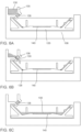
- FIG. 6 shows how a dual-purpose electrophoresis/lysis buffer can be added to an electrophoresis cell, such as the modular removable electrophoresis cell 120.
- the dual-purpose buffer 130 can be added manually wherein the user can pour the buffer 130 into the modular removable electrophoresis cell 120 in the region above the electrode 128, can close the instrument lid 102, and can initiate the assay through the integrated computer 110.
- Cell lysis can occur when the dual-purpose buffer 130 is poured into the removable electrophoresis cell 120. The user can initiate the run after adding the dual-purpose buffer 130.
- the instrument 100 can include a reservoir 135 which can contain the dual-purpose buffer 130 ( FIG. 6A ).
- the reservoir can have an initially closed valve 136 which can prevent the buffer 130 from exiting the reservoir.
- the software can programmatically control the release of the buffer 130 by opening a valve 136 allowing the buffer 130 to drain into the modular removable electrophoresis cell 120 ( FIG. 6B ).
- the computer processor may separately introduce a first solution and a second solution from the source of solution to the chip.
- the first and second solutions may be different, such as a lysis buffer and an electrophoresis buffer. Alternatively, the first and second solutions may be the same, such as washing buffers.
- the computer processor may be programmed to separately introduce two or more sequential solutions from the source of solution to the chip.
- the two or more sequential solutions may be the same.
- the two or more sequential solutions may be different.
- one or more solutions are manually introduced to the chip.
- one or more solutions are manually introduced and one or more solutions are programmatically introduced when the computer processor opens the reservoir valve 136.
- Programmatic control of buffer release can provide consistent timing of the lysis step.
- the buffer 130 can be released rapidly and can fill the removable electrophoresis cell 120 in less than about 1 second. In some instances, the buffer 130 can fill the removable electrophoresis cell 120 in less than about 0.5 seconds. In some instances, the buffer 130 can fill the removable electrophoresis cell 120 in less than about 0.1 seconds.
- the instrument 100 can include one or more active pumps. The instrument 100 can utilize gravity release to fill the reservoir 135 with buffer 130.
- the reservoir 135 can be configured to contain a single aliquot of buffer 130. In some instances, the entire volume of a single aliquot of buffer 130 can be released when the valve 136 is opened.
- the reservoir 135 can contain larger volumes of buffer 130, and a subvolume of the larger volume can be released for one assay.
- the release of a subvolume of buffer 130 can be controlled by the instrument 100.
- the instrument 100 can comprise multiple reservoirs and/or the buffer 130 can be introduced into the removable electrophoresis cell 120 at multiple locations.
- lysis buffers can contain high concentrations of surfactants and salts. These additives can assist in cell lysis. However, such additives can also increase the conductivity of the buffer making such buffers less suitable for electrophoresis as excessive electrical current can lead to joule heating and loss of separation resolution.
- the dual-purpose electrophoresis/lysis buffer 130 can therefore strike a balance between low conductivity for electrophoresis and the ability to lyse cells.
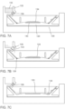
- separately-optimized electrophoresis and lysis buffers can be used. For example, FIG. 7 shows a scWB assay using a separate electrophoresis buffer 133 and lysis buffer 134.
- lysis buffer 134 can be added directly to the top surface of a chip, such as the disposable chip 140, to initiate lysis ( FIG. 7A ).
- a lysis time such as between about 5 to about 15 seconds
- a volume such as about 15 mL
- the electrophoresis buffer 133 can wash over the surface of the chip 140 and can displace the lysis buffer 134 and can wash it to the side of the removable electrophoresis cell 120 ( FIG. 7C ) where it can be diluted by the larger volume of electrophoresis buffer 133.
- This dilution can significantly mitigate the impact of the higher conductivity lysis buffer 134 during electrophoresis.
- the electrical resistance of the removable electrophoresis cell 120 can be largely determined by the thin layer of fluid directly above the chip 140 (defining the liquid height 131), therefore removing the lysis buffer 134 from the region above the chip 140 can greatly reduce the current during electrophoresis, independent of effect of dilution.
- a holding area below the electrode 128 can be created such that the lysis buffer 134 washes into the holding region thereby removing it from the electrical circuit entirely.
- FIGS. 8A-8C depict a device and method for performing antibody probing using a chip, which may be the scWB chip 140.
- the chip 140 may be consumable. In some cases, the chip 140 is disposable or reusable.
- the device can comprise an incubation chamber, such as an antibody probing fixture 150.
- the probing fixture 150 can contain a rectangular region with a defined depth or recession 151 with a length and width slightly smaller than the chip 140, as in FIG. 8A .
- the gel layer 142 containing immobilized proteins see FIG.
- the antibody fixtures can ensure a uniform gap that can be filled with antibody solution 138.
- the fixture 150 can be constructed of a hydrophobic material (such as PTFE) or can incorporate a hydrophobic coating such that the antibody solution cannot spread out from underneath the more hydrophilic gel layer 142. Keeping the antibody solution 138 contained under the chip 140 can reduce evaporation of the antibody solution 138.
- FIG. 8B Loading of the fixture is shown in FIG. 8B .
- a small volume of antibody solution 138 can be placed on the surface of the fixture. In some instances, the small volume can be less than about 100 microliters.
- the chip 140 with gel layer 142 facing down can then be rotated onto the fixture 150 as shown in FIG. 8B . Once the chip 140 has been lowered onto the fixture 150, the gap between the gel layer 142 and the bottom of the rectangular depression (recession) 151 can be filled with antibody solution 138. In some instances, the gap size 152 can be about 50 microns or less.
- the scWB consumable chip 140 can be allowed to incubate with the antibody solution 138 (see e.g., FIG. 8C ).
- the incubation is for about 30 to about 120 minutes. Extended incubation periods can be possible. Incubations may occur at reduced temperatures. During this incubation period, the entire fixture 150 may be covered to reduce evaporative losses. A small portion of wet cloth or paper may also be placed adjacent to the fixture 150 so as to further limit evaporative losses.
- the chip 140 can be removed from the fixture 150 by rotating the chip 140 away from the rectangular depression 151.
- a hydrophobic fixture can facilitate recovery of the used antibody solution 138 as the solution can tend to reform into a contiguous droplet when the chip 140 is rotated away from the fixture 150. Primary antibody solutions 138 may therefore be reused several times to reduce cost.
- FIGS. 8A-8C may be constructed using many common techniques such as machining, injection molding, or hot or cold embossing.
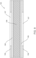
- FIG. 9 depicts a cross-sectional view of one construction for an antibody incubation fixture 155.
- a rectangular gap 157 can be formed on both sides of the fixture 155 using laminated layers.
- the core 156 of the fixture 155 may be constructed of any suitable, flat material such as for example, 0.125 inch thick poly(methyl methacrylate) (PMMA).
- Thin hydrophobic layers 158, such as 0.001 inch thick PTFE layers are then attached to the core layer 156.
- an additional hydrophobic layer having a rectangular region 159 removed can be attached to the first hydrophobic layer 158.
- the advantage of using laminated layers to define the gap size is that the laminated layers can be very flat over distances comparable to the size of the chip.
- the gap size of such a laminated device can be very uniform and can be defined by the thickness of the layer.
- the layers may be attached to each other using many techniques known to one skilled in the art, such as thermal bonding, solvent bonding, or use of intermediate pressure-sensitive adhesive layers.
- the first step of the scWB assay can be to settle cells into the array of the microwells formed into the gel layer 142. Once the cells are settled into wells, the user can gently rinse the chip 140 to remove cells that have not settled into wells substantially without washing cells out of microwells.
- FIG. 10 depicts another fixture 160 included with the system that can aid in rinsing of the chip 140 after cell settling.
- the rinsing fixture 160 can place the chip 140 at a shallow angle 161 which has a typical value of approximately 15 degrees. In other embodiments, the angle 161 can be greater than 15 degrees or less than 15 degrees.
- Wash buffer 139 can be ejected slowly from a pipette tip 162.
- the angle 161 of the rinsing fixture 160 can allow the wash buffer 139 to flow across the gel layer 142 at a controlled velocity thereby minimizing perturbation of cells that are trapped inside microwells while rinsing away cells that remain on the surface of the gel layer 142.
- the present disclosure also presents methods for obtaining molecular weight sizing of endogenous proteins contained in the cells.
- Separately optimized lysis and electrophoresis buffers can allow for the convenient introduction of protein standards.
- Preferential partitioning of proteins to open wells versus gel can allow for facile loading of protein markers that separate with the expected linear log molecular weight (MW) vs. mobility relationship.
- MW linear log molecular weight
- Protein markers can be fluorescently tagged using a distinct wavelength such that they do not interfere with later detection of endogenous proteins.
- the protein markers can be tagged with a cleavable or quenchable fluorophore which can be detected and then removed or quenched prior to detection of endogenous proteins.
- a cleavable or quenchable fluorophore which can be detected and then removed or quenched prior to detection of endogenous proteins.
- protein markers can be added to the lysis buffer such that they can be introduced simultaneously as cell lysis occurs.
- protein markers can be loaded into lysosomes or agarose (or other polymer) beads. The lysosomes and beads can then be settled simultaneously along with the cells resulting in some microwells containing marker proteins. Proteins can leave the lysosomes or beads when an external electric field is supplied to commence electrophoresis. An AC electric field can be applied to release the protein markers in a manner similar to electroporation of cells.
- the lysis buffer can be modified to release the protein markers from the lysosomes or beads.
- Protein sizing standards can be spotted onto a chip at various locations during manufacturing and rehydrated during use of the chip. Separate regions on a chip, such as alternating separate regions, may be designated for protein sizing ladders where the wells for the sizing ladders can be increased in at least one dimension to allow for more convenient loading of sizing markers.
- fluorescence standards such that detected endogenous proteins can be compared to a known fluorescence signal and measurements can more readily be compared between chips.
- the fluorescence standard can be introduced into the chip at discreet locations during manufacturing. Standards can be, for example, incorporated throughout the gel, or can be spotted onto regions of the chip before cross-linking of the gel has completed, or the reactive groups within the gel (e.g., benzophenone) may be activated to covalently bind the fluorescence standards. Fluorescence standards can be introduced in beads which co-settle into the wells along with cells.
- the beads can remain in the wells and the fluorescence signal from these beads can be compared to the signal from labeled, endogenous proteins that separate away from the wells.
- the beads can be commercially available silica beads (or the like), or they may be beads formed from a hydrogel.
- An example of a hydrogel bead includes polyacrylamide beads containing a benzophenone-methacrylamide co-monomer. Fluorescent dyes can be incorporated into the polyacrylamide bead by incubation with a desired dye followed by photo-initiated binding of the dye to benzophenone functional group incorporated into the hydrogel bead.
- Polyacrylamide beads can allow a user to conveniently add a desired marker to the beads. Beads can also incorporate magnetic nanoparticles to assist in manipulation of the beads.
- FIG. 11 shows a computer system 170 that is programmed or otherwise configured to implement systems and methods provided herein.
- the computer system 170 can regulate various aspects of analyte detection of the present disclosure, such as, for example, automated single cell western blogging.
- the computer system 170 can be an electronic device of a user or a computer system that is remotely located with respect to the electronic device.
- the electronic device can be a mobile electronic device.
- the computer system 170 includes a central processing unit (CPU, also "processor” and “computer processor” herein) 171, which can be a single core or multi core processor, or a plurality of processors for parallel processing.
- the computer system 170 also includes memory or memory location 172 (e.g., random-access memory, read-only memory, flash memory), electronic storage unit 173 (e.g., hard disk), communication interface 174 (e.g., network adapter) for communicating with one or more other systems, and peripheral devices 175, such as cache, other memory, data storage and/or electronic display adapters.
- the memory 172, storage unit 173, interface 174, and peripheral devices 175 are in communication with the CPU 171 through a communication bus (solid lines), such as a motherboard.
- the storage unit 173 can be a data storage unit (or data repository) for storing data.
- the computer system 170 can be operatively coupled to a computer network ("network") 176 with the aid of the communication interface 174 via a wired or wireless connection.
- the network 176 can be the Internet, an internet and/or extranet, or an intranet and/or extranet that is in communication with the Internet.
- the network 176 in some cases is a telecommunication and/or data network.
- the network 176 can include one or more computer servers, which can enable distributed computing, such as cloud computing.
- the network 176 in some cases with the aid of the computer system 170, can implement a peer-to-peer network, which may enable devices coupled to the computer system 170 to behave as a client or a server.
- the CPU 171 can execute a sequence of machine-readable instructions, which can be embodied in a program or software.
- the instructions may be stored in a memory location, such as the memory 172.
- the instructions can be directed to the CPU 171, which can subsequently program or otherwise configure the CPU 171 to implement methods of the present disclosure. Examples of operations performed by the CPU 171 can include fetch, decode, execute, and writeback, and/or any other suitable operation.
- the CPU 171 can be part of a circuit, such as an integrated circuit. One or more other components of the computer system 170 can be included in the circuit. In some cases, the circuit is an application specific integrated circuit (ASIC). In some embodiments, the CPU 171 and/or integrated circuit can include and/or can execute one or more modules associated with controlling the systems described herein. As used herein the term "module" refers to any assembly and/or set of operatively-coupled electrical components that can include, for example, a memory, a processor, electrical traces, optical connectors, software (executing in hardware), and/or the like.
- a module executed in the processor can be any combination of hardware-based module (e.g., a field-programmable gate array (FPGA), an ASIC, a digital signal processor (DSP)) and/or software-based module (e.g., a module of computer code stored in memory and/or executed at the processor) capable of performing one or more specific functions associated with that module.
- hardware-based module e.g., a field-programmable gate array (FPGA), an ASIC, a digital signal processor (DSP)
- software-based module e.g., a module of computer code stored in memory and/or executed at the processor
- the storage unit 173 can store files, such as drivers, libraries, profiles, saved programs, etc.
- the storage unit 173 can store user data, e.g., user preferences and user programs.
- the computer system 170 in some cases can include one or more additional data storage units that are external to the computer system 170, such as located on a remote server that is in communication with the computer system 170 through an intranet or the Internet (e.g., network attached storage (NAS) device).
- NAS network attached storage
- the computer system 170 can communicate with one or more remote computer systems through the network 176.
- the computer system 170 can communicate with a remote computer system of a user (e.g., service provider).
- remote computer systems include servers, host devices, personal computers (e.g., portable PC), slate or tablet PC's (e.g., Apple ® iPad, Samsung ® Galaxy Tab), telephones, Smart phones (e.g., Apple ® iPhone, Android-enabled device, Blackberry ® ), or personal digital assistants.
- the user can access the computer system 170 via the network 176.
- Methods as described herein can be implemented by way of machine (e.g., computer processor) executable code stored on an electronic storage location of the computer system 170, such as, for example, on the memory 172 or electronic storage unit 173.
- the machine executable or machine readable code can be provided in the form of software.
- the code can be executed by the processor 171.
- the code can be retrieved from the storage unit 173 and stored on the memory 172 for ready access by the processor 171.
- the electronic storage unit 173 can be precluded, and machine-executable instructions are stored on memory 172.
- the code can be pre-compiled and configured for use with a machine having a processer adapted to execute the code, or can be compiled during runtime.
- the code can be supplied in a programming language that can be selected to enable the code to execute in a pre-compiled or as-compiled fashion.
- aspects of the systems and methods provided herein can be embodied in programming.
- Various aspects of the technology may be thought of as “products” or “articles of manufacture” typically in the form of machine (or processor) executable code and/or associated data that is carried on or embodied in a type of machine readable medium.
- Machine-executable code can be stored on an electronic storage unit, such as memory (e.g., read-only memory, random-access memory, flash memory) or a hard disk.
- “Storage” type media can include any or all of the tangible memory of the computers, processors or the like, or associated modules thereof, such as various semiconductor memories, tape drives, disk drives and the like, which may provide non-transitory storage at any time for the software programming.
- All or portions of the software may at times be communicated through the Internet or various other telecommunication networks. Such communications, for example, may enable loading of the software from one computer or processor into another, for example, from a management server or host computer into the computer platform of an application server.
- another type of media that may bear the software elements includes optical, electrical and electromagnetic waves, such as used across physical interfaces between local devices, through wired and optical landline networks and over various air-links.
- the physical elements that carry such waves, such as wired or wireless links, optical links, or the like, also may be considered as media bearing the software.
- terms such as computer or machine "readable medium” refer to any medium that participates in providing instructions to a processor for execution.
- a machine readable medium such as computer-executable code
- a tangible storage medium such as computer-executable code
- Non-volatile storage media include, for example, optical or magnetic disks, such as any of the storage devices in any computer(s) or the like, such as may be used to implement the databases, etc. shown in the drawings.
- Volatile storage media include dynamic memory, such as main memory of such a computer platform.
- Tangible transmission media include coaxial cables, copper wires, and fiber optics, including the wires that comprise a bus within a computer system.
- Carrier-wave transmission media may take the form of electric or electromagnetic signals, or acoustic or light waves such as those generated during radio frequency (RF) and infrared (IR) data communications.
- Common forms of computer-readable media therefore include for example: a floppy disk, a flexible disk, hard disk, magnetic tape, any other magnetic medium, a compact disc-read only memory (CD-ROM), digital video disc (DVD) or digital video disc-read only memory DVD-ROM, any other optical medium, punch cards paper tape, any other physical storage medium with patterns of holes, a random-access memory (RAM), a read-only memory (ROM), a programmable read-only memory (PROM) and erasable programmable read-only memory (EPROM), a FLASH-EPROM, any other memory chip or cartridge, a carrier wave transporting data or instructions, cables or links transporting such a carrier wave, or any other medium from which a computer may read programming code and/or data.
- Many of these forms of computer readable media may be involved in carrying one or
- the computer system 170 can include or be in communication with an electronic display 177 that comprises a user interface (UI) 178 for providing, for example, an output or readout of the system coupled to the computer processor.
- UI user interface
- Examples of UI's include, without limitation, a graphical user interface (GUI) and web-based user interface.
- Methods and systems of the present disclosure can be implemented by way of one or more algorithms.
- An algorithm can be implemented by way of software upon execution by the central processing unit 171.
- the algorithm can, for example, be used to analyze results, such as the presence of one or more target analytes in a biological sample.
- a final data set can be constructed based on portions of data gathered from each assay of each biological sample.
- FIGS. 12A and 12B illustrate a removable electrophoresis cell 220 according to an embodiment.
- the removable electrophoresis cell 220 has been designed and/or otherwise optimized for manufacturing by injection molding. Portions of the removable electrophoresis cell 220 can be similar in form and/or function to corresponding portions and/or features of the electrophoresis cell 120 described above with reference to FIGS. 2-9 and thus, such portions are not described in further detail herein.
- the removable electrophoresis cell 220 includes wicking breaks 229 to prevent fluid from wicking up the electrodes to one or more contact pad areas 222.
- the electrophoresis cell 220 also includes an integrated chip lifter 265 that facilitates removal of a chip (e.g., the chip 140) from the cell 220.
- a chip e.g., the chip 140
- FIGS. 12A and 12B when the chip lifter 265 is in the down position, it fits flush with the electrophoresis body so as to prevent trapping of air bubbles as well as electric field perturbations that can be caused by changes in fluid height near the edge of the chip (as described in detail above with reference to the electrophoresis cell 120).
- the electrophoresis cell 220 includes weirs 224 that are inserted separately, allowing for the electrophoresis cell 220 to be molded.
- heat staking features 267 are included. The wire can be stretched between the heat staking features 267 which are then melted to permanently hold the wire in place.
- a small ( ⁇ 3 mm) circular recess 266 allows an alternate way of removing the chip from the electrophoresis cell 220 by using a pointed prying tool. The small size of the recess 266 minimizes bubble trapping and electric field perturbations. As shown in FIG.
- the underside of the electrophoresis cell 220 includes stabilization posts 269 which force the electrophoresis cell 220 to contact the receptacle in an instrument (e.g., the instrument 100) at fixed points.
- the electrophoresis cell 220 includes spout features 268 that can assist in pouring used buffer from the electrophoresis cell after use. In this manner, the electrophoresis cell 220 can be used in any suitable scWB process and/or procedure such as any of those described herein.
- An integrated opto-electronic instrument has been built that accurately controls all timed steps and provides uniform, repeatable, safe application of electric field and UV illumination for execution of the scWB assay.
- the integrated instrument minimizes the time between separation and UV photocapture, thus limiting diffusive dispersion and loss of separation resolution.
- mechanical interlocking of the high voltage and UV light has been implemented. Below, details on the optimized system components and demonstrate safe operation and acceptable assay performance of the integrated prototype are presented.
- Removable electrophoresis cell Iterative prototyping and design processes were employed to build, test, and optimize a removable electrophoresis cell for use in the final integrated scWB device.
- the design of the removable electrophoresis cell was configured to, for example, reduce electrolysis bubble formation near the electrodes that spread to cover the liquid surface within the cell, perturbing the electric field and blocking a portion of the UV light during the subsequent UV exposure step. Further, the design was configured to, for example, increase reliable chip adhesion and repeatable buffer addition.
- a chip recess can include finger cut-outs for facile chip removal.
- Such a chip recess can be sufficiently deep to protect the chip from being dislodged during buffer addition obviating the need for a petroleum jelly fixative.
- bubble trapping weir structures can be used to separate the platinum electrodes from the main cell compartment and prevent bubbles from floating over the chip surface.
- finger cut-outs can lead to, for example, electric field distortion observed at the edges of the chip (8° near edge vs. ⁇ 2° near center).
- a removable electrophoresis cell 220 includes a chip recess 221 configured to fully recess the chip such that the gel layer protruded beyond the chip recess 221 and finger cut-outs were removed (see FIG. 13 ).
- Such a removable electrophoresis cell 220 can incorporate the following designs: 1) A relatively large buffer reservoir allowing for the addition of lysis/electrophoresis buffer without spilling, 2) bubble traps (e.g., weirs 224) to prevent electrolysis bubbles from migrating over the surface of the chip and blocking UV light during photocapture while further damping fluid motion above the chip, 3) pogo-pin high-voltage contacts for integration with the instrument lid, and 4) the chip recess 221 without finger cutouts to minimize field distortion near the edges of the chip.
- the removable electrophoresis cell 200 can also include electrical contact pads 222 and a platinum electrode 227, as described above.
- Light source selection Several candidate light sources were tested. Benzophenone capture chemistries are known to be activated in the range of 330-360 nanometers (nm) and the Lightning cure lamp has a broad spectrum output with significant power at 316 nm and 365 nm. Several compact light sources in the 310 to 365 nm wavelength range were evaluated. No capture was observed under high power (1200 microWatts (mW)/cm 2 ) 365 nm LEDs (Hamamatsu). Compact UV fluorescent tube lamps were obtained from UV Systems (Renton, WA) and the performance of bulbs was compared with broad outputs centered at 365nm and 312 nm, respectively. Both bulbs have significant power output in the 330-360 nm range.
- the 312 nm wavelength bulb yielded a significant increase in capture efficiency compared to a 365 nm bulb (69% vs. 10% for a 4 minute exposure). Reducing the exposure time on the 312 nm bulb to 1 min yielded a measured mean capture efficiency of 52% (compared to 69% for a 4 min exposure time) suggesting that the exposure time can be reduced from 4 minutes with a moderate reduction in the capture efficiency.
- An integrated high-voltage electrophoresis and UV exposure unit is used to accurately control all timed steps and provide uniform, repeatable, safe application of electric fields and UV illumination.
- An integrated opto-electronic instrument 300 was built that incorporates the custom-designed removable electrophoresis cell 320, a chip 340 (such as those described above), and a 312 nm UV bulb from UV Systems to enable safe and automated sequential operation of electrophoresis and UV exposure steps (see e.g., FIGS. 14A-14D ).
- a touchscreen 310 with a graphical user interface was developed to allow users to have control over key assay steps: lysis time, electrophoresis run time, voltage, and UV exposure time ( FIGS. 14B and 14C ).
- Preferential partitioning of proteins to open wells versus gel allows for facile loading of protein markers that separate with the expected linear log MW vs. mobility relationship (see FIGS. 16A-16C ).
- the marker-containing buffer was removed to avoid continuous injection and reduced resolution of the protein markers during separation.
- the two-buffer workflow see, e.g., FIG. 7 .
- the ability to introduce molecular weight sizing protein markers in the lysis buffer has been shown.
- Surface tension holds the marker-containing lysis buffer on the surface of the gel, filling the wells, until the electrophoresis buffer is introduced and flows over the chip.
- introduction of the protein markers in the smaller volume of lysis buffer reduces the required mass (and cost) of ladder proteins by an order of magnitude.
- FIGS. 15A-15C illustrate molecular weight sizing on 8%T gel, 10%T gel, and 12%T gel, respectively.
- some embodiments herein relate to a computer storage product with a non-transitory computer-readable medium (also can be referred to as a non-transitory processor-readable medium) having instructions or computer code thereon for performing various computer-implemented operations.
- the computer-readable medium or processor-readable medium
- the media and computer code may be those designed and constructed for the specific purpose or purposes.
- non-transitory computer-readable media include, but are not limited to, magnetic storage media such as hard disks, floppy disks, and magnetic tape; optical storage media such as CDs, DVDs, CD-ROMs, and holographic devices; magneto-optical storage media such as optical disks; carrier wave signal processing modules; and hardware devices that are specially configured to store and execute program code, such as ASICs, Programmable Logic Devices (PLDs), Read-Only Memory (ROM), and Random-Access Memory (RAM) devices.
- PLDs Programmable Logic Devices
- ROM Read-Only Memory
- RAM Random-Access Memory
- Other embodiments described herein relate to a computer program product, which can include, for example, the instructions and/or computer code discussed herein.
- Hardware modules may include, for example, a general-purpose processor, a field programmable gate array (FPGA), and/or an ASIC.
- Software modules (executed on hardware) can be expressed in a variety of software languages (e.g., computer code), including C, C++, Java TM , Ruby, Visual Basic TM , and/or other object-oriented, procedural, or other programming language and development tools.
- Examples of computer code include, but are not limited to, micro-code or micro-instructions, machine instructions, such as produced by a compiler, code used to produce a web service, and files containing higher-level instructions that are executed by a computer using an interpreter.
- embodiments may be implemented using imperative programming languages (e.g., C, FORTRAN, etc.), functional programming languages (Haskell, Erlang, etc.), logical programming languages (e.g., Prolog), object-oriented programming languages (e.g., Java, C++, etc.) or other suitable programming languages and/or development tools.
- Additional examples of computer code include, but are not limited to, control signals, encrypted code, and compressed code.
Landscapes
- Life Sciences & Earth Sciences (AREA)
- Health & Medical Sciences (AREA)
- Molecular Biology (AREA)
- Chemical & Material Sciences (AREA)
- Physics & Mathematics (AREA)
- Biochemistry (AREA)
- Pathology (AREA)
- Analytical Chemistry (AREA)
- Chemical Kinetics & Catalysis (AREA)
- General Health & Medical Sciences (AREA)
- General Physics & Mathematics (AREA)
- Immunology (AREA)
- Electrochemistry (AREA)
- Spectroscopy & Molecular Physics (AREA)
- Apparatus Associated With Microorganisms And Enzymes (AREA)
- Investigating, Analyzing Materials By Fluorescence Or Luminescence (AREA)
- Investigating Or Analysing Biological Materials (AREA)
- Investigating Or Analysing Materials By Optical Means (AREA)
- Peptides Or Proteins (AREA)
Description
- The present disclosure concerns devices, systems, and methods for assaying a biological sample for a presence of one or more target analytes, such as target proteins.
- Understanding cell-to-cell variation in protein expression is a large part of understanding the pathogenesis of tumors, characterizing the differentiation states of stem cells, and developing well-controlled and functionally-validated in vitro human 'disease in a dish' models for drug development, target screening, and toxicity studies. Single-cell analysis is of growing importance, but has been largely limited to transcriptome (e.g., RNA) and genome (e.g., DNA) technologies. Importantly, these measurements do not always correlate with the protein levels that dictate phenotype. Single-cell protein measurements represent an unsurmounted hurdle in stem cell, cancer, and immunology research.
- Methods to determine protein level expression of a biological sample include electrophoresis followed by probe analysis. Electrophoresis is a technique that typically applies an electric field to a biological sample in a separation medium, such that individual molecules of the biological sample will disperse throughout the separation medium based on molecular size and charge. Cell lysis prior to electrophoresis, may reduce the biological sample to a set of individual molecules that can effectively separate throughout the separation medium. Cell lysis, electrophoresis, and subsequent probe analysis are typically executed on separate platforms with extensive user manipulation.
WO 2014/178107 A1 discloses an electrophoresis device comprising a holder defining a recess area containing a cassette with gel such that the top surface of the cassette is flush with a non-recessed surface of the holder, and an electrode for producing an electric field across the recess area. -
US 2006/292649 A1 discloses methods and apparatus for reference lab diagnostics, wherein target analytes are resolved by isoelectric focusing in channels of a microfabricated silicon device which is located in a recess area of a holder provided with electrodes producing an electric field across the recess area. -
US 8,562,802 B1 discloses a transilluminator base and scanner for imaging fluorescent gels, charging devices and portable electrophoresis systems.US 4,911,816 A discloses a cartridge for conducting electrophoresis in view of separation and subsequent transfer of macromolecules to a membrane to facilitate detection thereof. The electrophoresis cartridge comprises a tray with a bottom surface defining a recess area containing a support covered by a fluid-permeable membrane which binds nucleic acids, an electrode for producing an electric field across the recess area, and a dam disposed at the end of the tray for controlling the flow of solution below the dam and across the recess area. - Thus, a need exists for devices, systems, and methods for assaying for a presence of various types of analytes using a single, self-contained system.
- The scope of protection of the present invention is defined in the appended claims.
- The novel features of the present invention are set forth in the appended claims. A better understanding of the features and advantages of the present invention will be obtained by reference to the following detailed description that sets forth illustrative embodiments, in which the principles of the present invention are utilized, and the accompanying drawings (also "figure" and "FIG." herein), of which:
-
FIG. 1 illustrates a single cell Western Blotting (scWB) array image and assay workflow schematic, according to an embodiment. -
FIG. 2 illustrates a main unit of a scWB apparatus, according to an embodiment. -
FIG. 3 illustrates a receptacle of themain unit 100 ofFIG. 2 that holds a modular electrophoresis cell which itself may contain a removable chip. -
FIG. 4 illustrates one embodiment of a modular removable electrophoresis cell configured for use in themain unit 100 of the scWB apparatus ofFIG. 2 . -
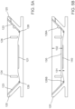
FIGS. 5A and 5B illustrate cross-sectional views of the modular removable electrophoresis cell ofFIG. 4 , containing a removable chip. -
FIGS. 6A-7C illustrate cross-sectional views of the modular removable electrophoresis cell ofFIG. 4 , in fluid communication with a reservoir and valve features for addition of one or more buffer solutions into the reservoir of the modular removable electrophoresis cell ofFIG. 4 . -
FIGS. 8A-8C illustrate a device for performing antibody probing of a removable chip according to an embodiment. - FIGS. 9A-9C illustrates a cross-sectional view of an alternate construction for an antibody incubation fixture according to an embodiment.
-
FIG. 10 illustrates a rinsing fixture according to an embodiment. -
FIG. 11 shows a computer control system that is programmed or otherwise configured to implement any of the methods provided herein. -
FIGS. 12A and 12B illustrate a removable electrophoresis cell according to an embodiment. -
FIG. 13 illustrates a removable electrophoresis cell according to an embodiment. -
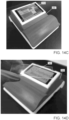
FIG. 14A illustrates a scWB apparatus with an open lid showing the removable electrophoresis cell according to an embodiment. -
FIGS. 14B and14C illustrate an exterior view of the scWB apparatus ofFIG. 14A showing a touchscreen feature. -
FIG. 14D illustrates a scWB removable chip configured for use with the scWB apparatus ofFIG. 14A . -
FIG. 15A-15C illustrate measurements of beta-tubulin in CHO cells performing a scWB assay via, for example, the scWB apparatus ofFIGS. 14A-14D . -
FIGS. 16A-16C illustrate molecular weight sizing on 8%T gel, 10%T gel, and 12%T gel, respectively. - While various embodiments of the present invention have been shown and described herein, it will be obvious to those skilled in the art that such embodiments are provided by way of example only. Numerous variations, changes, and substitutions may occur to those skilled in the art without departing from the present invention. It should be understood that various alternatives to the embodiments described herein may be employed
- As used in this specification, the singular forms "a," "an" and "the" include plural referents unless the context clearly dictates otherwise. Thus, for example, the term "a member" is intended to mean a single member or a combination of members, "a material" is intended to mean one or more materials, or a combination thereof.
- As used herein, the term "protein" refers to proteins, oligopeptides, peptides, and analogs, including proteins containing non-naturally occurring amino acids and amino acid analogs, and peptidomimetic structures.
- As used herein, the term "analyte" refer to any molecule or compound to be detected, as described herein. Suitable analytes can include but are not limited to, small chemical molecules such as, for example, environmental molecules, clinical molecules, chemicals, pollutants, and/or biomolecules. More specifically, such chemical molecules can include but are not limited to pesticides, insecticides, toxins, therapeutic and/or abused drugs, hormones, antibiotics, antibodies, organic materials, proteins (e.g., enzymes, immunoglobulins, and/or glycoproteins), nucleic acids (e.g., DNA and/or RNA), lipids, lectins, carbohydrates, whole cells (e.g., prokaryotic cells such as pathogenic bacteria and/or eukaryotic cells such as mammalian tumor cells), viruses, spores, polysaccharides, glycoproteins, metabolites, cofactors, nucleotides, polynucleotides, transition state analogs, inhibitors, nutrients, electrolytes, growth factors and other biomolecules and/or non-biomolecules, as well as fragments and combinations thereof. Some analytes described herein can be proteins such as enzymes, drugs, cells, antibodies, antigens, cellular membrane antigens, and/or receptors or their ligands (e.g., neural receptors or their ligands, hormonal receptors or their ligands, nutrient receptors or their ligands, and/or cell surface receptors or their ligands).
- As used herein, the term "sample" refers to a composition that contains an analyte or analytes to be detected. A sample can be heterogeneous, containing a variety of components (e.g., different proteins) or homogenous, containing one component. In some instances, a sample can be naturally occurring, a biological material, and/or a man-made material. Furthermore, a sample can be in a native or denatured form. In some instances, a sample can be a single cell (or contents of a single cell) or multiple cells (or contents of multiple cells), a blood sample, a tissue sample, a skin sample, a urine sample, a water sample, and/or a soil sample. In some instances, a sample can be from a living organism, such as a eukaryote, prokaryote, mammal, human, yeast, and/or bacterium or the sample can be from a virus. In some instances, a sample can be one or more stem cells (e.g., any cell that has the ability to divide for indefinite periods of time and to give rise to specialized cells). Suitable examples of stem cells can include but are not limited to embryonic stem cells (e.g., human embryonic stem cells (hES)), and non-embryonic stems cells (e.g., mesenchymal, hematopoietic, induced pluripotent stem cells (iPS cells), or adult stem cells (MSC)).
- The term "level," as used herein, generally refers to variation from a plane that is orthogonal to the gravitational acceleration vector.
- The present disclosure is directed to automated systems for performing analyte detection, such as western blotting. Systems provided herein can be used to detect analytes in samples of substantially low volume, such as single cell analysis. In some examples, such analysis can be performed using single cell western blotting (scWB), which employs microfluidic design to introduce tried-and-true microarray formats that combine: (i) protein molecular weight determination via electrophoresis with (ii) protein identity determination via subsequent antibody-based probing of resolved protein bands. This two-stage assay can include western blotting. This two-stage analysis can offer ultra-high specificity performance at the bench, without the need for costly infrastructure or core facilities. The scWB brings high-specificity protein assays to single-cells, while taking advantage of the vast reagent infrastructure already available for conventional western blotting.
- Widespread implementation of scWB can impact biomedicine through: a) elucidating intratumor cell-to-cell heterogeneity, thus advancing therapeutic efficacy of cancer drugs; b) assessing patient-specific cell-level response for companion diagnostics to targeted therapy drug cocktails; c) quantifying the purity and safety of cell-based therapies before implantation, which may accelerate regulatory approval and lead to the creation of safer, more effective cell-based therapies; d) enabling analysis of rare cell populations from patients (e.g., circulating tumor cells, CTCs) for targeted therapies; and e) enabling characterization of rare cell therapies such as iPSC-derived somatic cells to accelerate creation of functional tissues and in vitro disease models for drug development. Single-cell western-based protein-level information may provide a transformative leap towards realizing personalized and regenerative medicine.
- To achieve microarray-like density of single-cell resolution western blots, the scWB can use a microscope slide coated with a thin photoactive polymer stippled with thousands of microwells having a diameter that is about 100 microns or less. In some embodiments, each microwell can have a diameter in a range of about 15 microns to about 45 microns in diameter (see e.g.,
FIG. 1 ). The chip can be fabricated using soft lithography. The chip can be removable, consumable, disposable, or combinations thereof. The chip can be a scWB chip. The scWB workflow can initiate when a cell suspension is dispensed on top of the microwell array having a gel, with single cells settling into individual microwells passively under the action of gravity. Microwell occupancy can be controlled by limiting dilution and microwell design (e.g., microwells sized to accommodate single cells). After cell lysis and application of an electric field across the gel, the photo-active gel, which can comprise benzophenone-methacrylamide, can act as a sieving matrix that separates molecules (such as proteins) according to their molecular weight over short separation distances (<1 mm). With a brief UV exposure, the benzophenone-methacrylamide co-monomer can covalently immobilize proteins via hydrogen abstraction, which can yield capture efficiencies approaching 100%. Thus, protein bands can be fixed in position in the gel after the size-based separation and subsequently the gel can be probed with antibodies which can obviate the transfer and blocking steps typically used in traditional western blotting approaches. In some instances, a scWB can be performed without pumps, valves, precise alignment or complex electrical or pneumatic interfaces typically found in scWB systems (e.g., mass spectrometers, mass cytometry, flow cytometers, etc.). Multiplexing of targets can be achieved by size separation, multispectral detection, and/or repeated stripping and re-probing of the captured proteins. - On one microscope slide, thousands or more of single cells can be assayed in parallel and as little as about 1-10 femtograms or less of target protein per cell can be detected which, in some instances, can impart higher throughput and analytical sensitivity than mass spectrometry. Given the widespread use of conventional western blotting and less strict antibody specificity requirements, about 10 times more commercially-available antibodies can be validated for western blotting as compared to flow cytometry. Cell lysis can allow for measurement of diverse targets such as intracellular proteins, protein complexes, and post-translational modifications that may not accessible using flow cytometry.
- Flow cytometry is an established single-cell proteomic tool with high throughput. Yet flow cytometry can require high antibody specificity and intracellular proteins can be more challenging to detect. Mass cytometry can make single-cell proteomic measurements but may use custom heavy metal-tagged antibodies, expensive instrumentation (e.g., $600,000 per instrument) and high antibody specificity. Mass spectrometry is emerging as a single-cell analysis tool, yet it may require expert spectra interpretation, and can have low throughput and low analytical sensitivity. Automated western blotting instrumentation exists but is unable to reach single-cell resolution. In some instances, this is attributable in part to capture efficiencies of about 0.01% versus about 100% for the scWB.
- In some embodiments, a system for scWB can include instrumentation that can integrate the electrophoresis and UV capture steps. The present disclosure described here also provides for safety interlocking (to prevent user exposure to hazardous high voltage and UV light) and enables integrated electrophoresis and UV exposure on a microscope slide format. While the initial application of the instrument can perform the scWB assay, the same present disclosure can enable related assays such as small volume (but not single-cell) western blotting or small volume, parallel electrophoresis assays.
- The present disclosure presents a system for performing electrophoretic separations and photocapture of separated molecules within a thin gel attached to a planar substrate. The system can perform single-cell resolution western blotting (scWB) in a thin (<100 micron thick) gel layer on a microscope slide. It can be a system comprising an instrument, software, associated accessories, and assay methods.
- The system is shown in
FIG. 2 . The main unit 100 (also referred to herein as "instrument" and/or "device") can be comprised of abase 101, alid 102, an integrated computer (such as a tablet computer with a touch screen, 110), a high voltage power supply (that can be contained in a compartment 105) and a source of activation energy (e.g., radiation energy) such as an ultraviolet (UV)light source 108. Themain unit 100 is configured to receive anelectrophoresis cell 120 and can be used to perform an assay on a biological sample included in and/or otherwise contained by theelectrophoresis cell 120, as described in further detail herein. The system can be controlled by a computer, microprocessor or microcontroller which can either be integrated into themain unit 100 or separate from but in communication with the main instrument body or housing (e.g., through a wired or wireless data connection). Integration of a computer with the instrument body can allow for flexible integration of instrument control and data management in a compact form. For example, thetablet computer 110 can have a built-in sensor (e.g., camera) that can be used to read barcodes printed on a chip, for example, a scWB consumable chip. The chip can be adapted, configured, or otherwise suitable for use in scWB. The sensor can be used to read or identify one or more identification members, such as identification numbers, on the removable electrophoresis cell. Each of the one or more identification members can be unique. The one or more identification members can include one-dimensional or two-dimensional identification barcodes. The one or more identification members can include radio frequency identification (RFID) units. The sensor can store the one or more identification members, such as identification numbers, in memory coupled to the computer processor. The memory can be part of the system or a remote computer system, such as a remote server in network communication with the system (e.g., the "cloud"). A first identification member of the one or more identification members can determine a first set of assay parameters for the assaying. The computer processor can be programmed to upload the first unique identification member, the first set of assay parameters, or a combination thereof to a computer network. In some cases, the instrument can include detection of the presence of one or more target analytes and the computer processor can be programed to upload the presence of one or more target analytes. The barcode can then be used to determine a set of assay parameters to be used for running the barcoded chip. Once the run is complete, the tablet can upload run information along with the barcode to a computer network, such as a network server. The server can later be accessed by a separate reader instrument so that imaging data and electrophoresis run data can be associated with the same chip through the barcode. - The
main unit 100 can include aframe 109 which can position and hold the touch screen ortablet computer 110 and can hide any cable connections to the tablet computer or screen. The source of activation energy, such as theUV light source 108, can be a fluorescent bulb, LED, an Hg-Xe source, or other common sources. The instrument body can include acurved surface 112 to accommodate a cylindrical-shaped UV source (such as a fluorescent lamp) while maintaining a compact and aesthetically pleasing profile. The exterior face of the UVlight source 108 can be an optical filter or a window that can reduce the light intensity (e.g., a neutral density filter) or that can control the wavelengths of light that pass through such that optimal wavelengths can reach the scWB consumable chip. The filter or window can be heated or treated with a coating to reduce condensation of buffer during electrophoresis. - In some embodiments, sensitive and high voltage components can be sealed within a
separate compartment 105 so that any liquid (e.g., buffer solution) spilled inside theinstrument 100 cannot come in contact with the electronics. In such an example, air cooling and venting can occur from the bottom of the instrument. Thelid 102 can rotate open aboutaxis 103 and can be supported by afriction hinge 104 which can allow thelid 102 to stay open at various angles. Thelid 102 can close if opened less than a threshold angle (e.g., 10 degrees or any other suitable angle). Thelid 102 may include dampening mechanisms to slow thelid 102 closure, and can latch closed using one of various methods known to one skilled in the art (e.g., magnetic or mechanical latches). Levelingfeet 111 can be used to level theinstrument base 101 such that liquid (e.g., buffer solution) in theelectrophoresis cell 120 can be level. Leveling can be accomplished by placing a standard bubble level in theelectrophoresis cell 120 while adjusting the levelingfeet 111 or theinstrument 100 can include a permanently mounted bubble level or an electronic leveler that can interface to thecomputer 110 which in turn can inform the user if theinstrument 100 is level. In some embodiments, theinstrument 100 can include any suitable device and/or mechanism configured to automatically or at least semi-automatically level the instrument. - In an example, a chip 140 (
FIG. 5 ), such as a disposable or consumable chip that is 75 mm long, being 1 degree "off level" can have a fluid height that can vary by 1.3 mm across the top of the chip. If the nominal height of the fluid 404 (FIG. 5 ) is only 3 mm, then being off level can result in about a 40% variation in fluid height which can result in a 40% variation in the electric field. - Interlock switches 107 can ensure that the
lid 102 is closed before hazardous UV and high voltage (HV) are enabled. Theinstrument 100 can be configured to disconnect the HV power supply from the pogo pins 114 when thelid 102 is opened and/or the HV supply can be disabled and the residual charge can be dissipated to ground. The main body of theinstrument 100 may include vents which can prevent accumulation of explosive electrolysis gases inside the instrument body. Light blocking features (such as a raised rim around thebase 101 of the instrument 100) may be included, which can minimize any leakage of UV light when thelid 102 is closed. - As shown in
FIG. 3 , the main instrument body or housing can include areceptacle 106 that can hold anelectrophoresis cell 120. In some instances, theelectrophoresis cell 120 can be modular, removable, or a combination thereof. In an example, an electrophoresis cell, such as the modularremovable electrophoresis cell 120 can be aligned using one or more alignment pins 113 which can interface to corresponding slots and/or holes on the modularremovable electrophoresis cell 120. This modular design can allow for any number of removable electrophoresis cell designs to be used in themain instrument unit 100. Some such designs can accommodate different chips which can fit into arecess area 121 of theelectrophoresis cell 120, different electrode configurations, or electrical resistance that can simulate a filled removable electrophoresis cell to allow for convenient dry testing of the system. In some embodiments, any number of slots can be formed in the main instrument body or housing to accommodate the one or more pins. An electrical connection can be formed when one or more pins are adjacent to the one or more conductive pads of theremovable electrophoresis cell 120. In an example, the slots can be configured to accommodate various removable electrophoresis cell form factors and/or various electrode configurations. In an example, the slots can remain spatially fixed and the pin configuration can be modular. In another example, the slots and pin configuration of the housing can remain spatially fixed and the configuration of the contact pads of the modular removable electrophoresis cell can also remain spatially fixed. In this example, the electrical connections and mechanical features within the modular electrophoresis cell can be reconfigured for different functions, such as a plurality of removable electrophoresis cell designs. - Electrical connection can be made to the
removable electrophoresis cell 120 via spring-loaded pins, i.e., "pogo pins," 114 which can connect toconductive contact pads 122 on theelectrophoresis cell 120. This interface can allow for dry contact to the HV pogo pins 114. Theelectrical contact pads 122 can be connected to conductors (for example, platinum or carbon conductors) which can contact the liquid (e.g., buffer solution) in theremovable electrophoresis cell 120. Theinstrument 100 can control the voltage difference between the pogo pins 114 such that the electric field strength in the removable electrophoresis cell can be programmatically controlled. In an example, theinstrument 100 can programmatically change the polarity of the pogo pin voltages such that the direction of the electric field within the removable electrophoresis cell can also be controlled via software. Additional pins and contact pads may be added to accommodate different removable electrophoresis cell designs, if more than two voltages are needed. Although not shown, in some embodiments, thereceptacle 106 is surrounded by a grounding ring such that any fluid that spills outside of theelectrophoresis cell 120 during operation will be electrically grounded once it crosses over the grounding ring. The grounding ring can be any suitable shape, size, and/or configuration and can be formed from any suitable grounding material. - The
receptacle 106 and removable electrophoresis cells can be transparent such that an additional UV light source can be included below thereceptacle 106. The transparent surfaces can include lens elements to help focus light from a UV source. The imaging instrumentation (e.g., lenses, cameras, photodetectors, etc.) can be included below thereceptacle 106. The imaging instrumentation can enable brightfield or fluorescence imaging of the chip, before, during, or after electrophoresis. In an example, the surface of thereceptacle 106 can be reflective such that UV light from theUV source 108 can be reflected back to the chip to increase the UV flux. In another example, the surface of thereceptacle 106 can include ultrasonic transducers (or the like) which can transmit energy to a chip seated in therecess area 121 and can assist in lysis of cells contained within the chip. In a further example, thereceptacle 106 can incorporate temperature control (heaters and/or coolers) to assist with lysis, to control heating during electrophoresis, or to provide temperature cycling or control for desired chemical reactions (e.g., for melting or annealing of nucleic acid-tagged detection probes). -
FIG. 4 shows an example of an electrophoresis cell, such as theremovable electrophoresis cell 120. Theremovable electrophoresis cell 120 can have a body 120A that defines therecess area 121 designed to accommodate achip 140, an example of which can be a scWB consumable chip having outer dimensions equal to a standard microscope slide.Conductive contact pads 122 are coupled to the body 120A and can provide an electrical interface to the instrument.Platinum wire 127 can connect from thecontact pads 122 into the body 120A of theremovable electrophoresis cell 120. Theplatinum wire 127 can be inserted into nonconductive tubing such that the portion of thewire 127 outside of theremovable electrophoresis cell 120 can be electrically insulated while at least of portion of the tubing can be removed so that theplatinum wire 127 inside of theremovable electrophoresis cell 120 can be exposed to facilitate contact with the buffer. To maximize activation energy flux onto the scWBconsumable chip 140, theremovable electrophoresis cell 120 can be shallow to minimize the distance between the top of the slide and the source of activation energy, such as a UV source. Theremovable electrophoresis cell 120 can incorporate features to avoid wicking of the electrophoresis buffer outside of a shallowremovable electrophoresis cell 120. For example,internal corners 123 may be radiused to reduce wicking. In an example, theremovable electrophoresis cell 120 can include pouring or spout features to aid in emptying the removable electrophoresis cell when the assay is complete. -
FIG. 5 shows a cross-sectional view of an electrophoresis cell, such as a modularremovable electrophoresis cell 120. Thechip 140 can sit flush inside of therecess area 121 such that the thin gel layer on the top surface of thechip 140 can be level with the bottom of theremovable electrophoresis cell 120. In an example, thechip 140 can sit flush within therecess area 121 to minimize or eliminate changes in height that can cause electric field distortions or perturbations near the edge of thechip 140. Electric field distortions or perturbations can cause variations in the migration distance and in the direction of protein bands that are separated in thechip 140. Electrical field distortions can be spatial distortions or perturbations, such as distortions near the edge of thechip 140. Electrical field distortions can be temporal distortions or perturbations, such as bubbles passing over thechip 140. Electrical current can be proportional to afluid height 131 and the fluid can absorb some of the UV light from the UVlight source 108. In some instances, the fluid or liquid height (e.g., buffer solution height) can be minimized. Selection of the electrophoresis cell dimensions can minimize liquid height. Thefluid height 131 may be less than about 50 millimeters (mm), 20 mm, 30 mm, 10 mm, 8 mm, 6 mm, 5 mm, 4 mm, 3 mm, 2 mm, or 1 mm. In some instances, adistance 132 between thechip 140 and the top of theremovable electrophoresis cell 120 can be reduced to increase the flux of UV light from the UVlight source 108 onto thechip 140. The electrophoresis cell dimensions may be selected so as to reduce thefluid height 131 and increase the flux or power of UV light. - The
distance 132 may be less than or equal to about 25 mm, 20 mm, 15 mm, 14 mm, 13 mm, 12 mm, 11 mm, 10 mm, 5 mm, 4 mm, 3 mm, 2 mm, or 1 mm. In some instances, thedistance 132 is between about 1 mm and 50 mm, or 5 mm and 20 mm. - The
removable electrophoresis cell 120 can be designed so that the depth of theelectrophoresis buffer 130 is deeper near theelectrodes 128 such that the electrodes can be covered by the electrophoresis buffer while allowing for asmaller fluid height 131 above thechip 140. In some instances, the electric field strength and migration distances can vary across thechip 140 unless the liquid (e.g., buffer solution)height 131 is uniform across thechip 140. In the example shown inFIG. 5 , a uniformliquid height 131 can be achieved by leveling theremovable electrophoresis cell 120, e.g., using a bubble level or electronic level while adjusting theinstrument feet 111, while thefluid height 131 can be controlled by the volume ofelectrophoresis buffer 130 that is added to theremovable electrophoresis cell 120. Leveling features can be attached to the modularremovable electrophoresis cell 120 or be integrated into thereceptacle 106 such that theremovable electrophoresis cell 120 can be leveled independent of the main instrument body orhousing 100. - In an example, the
removable electrophoresis cell 120 can be configured such that thelid 102 defines thefluid height 131 by creating a fixed distance between thelid 102 and surface of thechip 140. Excess liquid (e.g., buffer solution) can be displaced such that thefluid height 131 is no longer a function of the volume ofelectrophoresis buffer 130 or whether or not theremovable electrophoresis cell 120 is level. Thefluid height 131 can be controlled by spillover features so that once the target fluid level is reached, excess buffer can flow over the spillover feature into a reservoir such that the excess buffer addition does not change thefluid height 131. - The modular
removable electrophoresis cell 120 incorporates one ormore weir structures 124. Theseweir structures 124 can prevent electrolysis bubbles, which can be generated at theelectrodes 128, from drifting over thechip 140. Bubbles above thechip 140 can distort or perturb the electric field and may block activation energy (e.g., UV light) from the source of activation energy (e.g., UV light source) 108. When the electrophoresis buffer is poured into the removable electrophoresis cell in the region above theelectrodes 128, theweir structures 124 can prevent bubbles already present in the buffer from flowing across thechip 140. Theweir structures 124 can help dampen fluid motion after pouring such that thebuffer 130 can become quiescent more rapidly than in aremovable electrophoresis cell 120 without one or more weir structures. In some instances, the dampening of fluid motion can be important to reduce loss of proteins from the microwells during lysis. Theremovable electrophoresis cell 120 can further incorporate a sieve or one or more other features that filter out bubbles already present in the electrophoresis buffer or generated by electrolysis. - The modular
removable electrophoresis cell 120 can comprise one or more structures (126A, 126B) to capture and restrain theelectrode wire 127. Ahole 125 in the wall of theremovable electrophoresis cell 120 can allow theelectrode wire 127 to pass through the wall and to connect electrically to thecontact pads 122. Thewire 127 can be sheathed in a nonconductive tube (such as polytetrafluoroethylene (PTFE)). Thewire 127 can be sheathed in a nonconductive tube at the point where it passes through thehole 125 such that thewire 127 can be electrically insulated outside of thecell 120. - In some instances, when loading the
chip 140, such as a disposable chip, into the modularremovable electrophoresis cell 120, air can be trapped under thechip 140. Air may remain trapped when the electrophoresis buffer is added to theremovable electrophoresis cell 120 and can result in thechip 140 floating up or bubbles escaping along the edges of thechip 140 during electrophoresis, which can distort or perturb the electric field. A droplet of buffer (e.g., 50-300 microliters) can be added to therecess area 121. In some instances, a droplet of buffer can be added to one side of therecess area 121 or can be added prior to loading thechip 140 into therecess area 121 after which thechip 140 can be lowered into therecess area 121, allowing the liquid drop to wick underneath thechip 140 to exclude any trapped air. The surface tension of the liquid (e.g., buffer solution) under the slide (e.g., chip) can hold the slide in therecess area 121 until the electrophoresis buffer can be added to thecell 120. Therecess area 121 can be opaque or dark color which can increase the visual contrast between the air and liquid under thechip 140. -
FIG. 6 shows how a dual-purpose electrophoresis/lysis buffer can be added to an electrophoresis cell, such as the modularremovable electrophoresis cell 120. In some examples, the dual-purpose buffer 130 can be added manually wherein the user can pour thebuffer 130 into the modularremovable electrophoresis cell 120 in the region above theelectrode 128, can close theinstrument lid 102, and can initiate the assay through theintegrated computer 110. Cell lysis can occur when the dual-purpose buffer 130 is poured into theremovable electrophoresis cell 120. The user can initiate the run after adding the dual-purpose buffer 130. - The
instrument 100 can include areservoir 135 which can contain the dual-purpose buffer 130 (FIG. 6A ). The reservoir can have an initiallyclosed valve 136 which can prevent thebuffer 130 from exiting the reservoir. The software can programmatically control the release of thebuffer 130 by opening avalve 136 allowing thebuffer 130 to drain into the modular removable electrophoresis cell 120 (FIG. 6B ). The computer processor may separately introduce a first solution and a second solution from the source of solution to the chip. The first and second solutions may be different, such as a lysis buffer and an electrophoresis buffer. Alternatively, the first and second solutions may be the same, such as washing buffers. - The computer processor may be programmed to separately introduce two or more sequential solutions from the source of solution to the chip. The two or more sequential solutions may be the same. As an alternative, the two or more sequential solutions may be different. In some instances, one or more solutions are manually introduced to the chip. As an alternative, one or more solutions are manually introduced and one or more solutions are programmatically introduced when the computer processor opens the
reservoir valve 136. - Programmatic control of buffer release can provide consistent timing of the lysis step. The
buffer 130 can be released rapidly and can fill theremovable electrophoresis cell 120 in less than about 1 second. In some instances, thebuffer 130 can fill theremovable electrophoresis cell 120 in less than about 0.5 seconds. In some instances, thebuffer 130 can fill theremovable electrophoresis cell 120 in less than about 0.1 seconds. Theinstrument 100 can include one or more active pumps. Theinstrument 100 can utilize gravity release to fill thereservoir 135 withbuffer 130. Thereservoir 135 can be configured to contain a single aliquot ofbuffer 130. In some instances, the entire volume of a single aliquot ofbuffer 130 can be released when thevalve 136 is opened. In some instances, thereservoir 135 can contain larger volumes ofbuffer 130, and a subvolume of the larger volume can be released for one assay. The release of a subvolume ofbuffer 130 can be controlled by theinstrument 100. In some instances, theinstrument 100 can comprise multiple reservoirs and/or thebuffer 130 can be introduced into theremovable electrophoresis cell 120 at multiple locations. - Many lysis buffers can contain high concentrations of surfactants and salts. These additives can assist in cell lysis. However, such additives can also increase the conductivity of the buffer making such buffers less suitable for electrophoresis as excessive electrical current can lead to joule heating and loss of separation resolution. The dual-purpose electrophoresis/
lysis buffer 130 can therefore strike a balance between low conductivity for electrophoresis and the ability to lyse cells. In some instances, separately-optimized electrophoresis and lysis buffers can be used. For example,FIG. 7 shows a scWB assay using aseparate electrophoresis buffer 133 andlysis buffer 134. Approximately 1 mL oflysis buffer 134 can be added directly to the top surface of a chip, such as thedisposable chip 140, to initiate lysis (FIG. 7A ). After a lysis time (such as between about 5 to about 15 seconds), a volume (such as about 15 mL) ofelectrophoresis buffer 133 can be released from areservoir 135, as inFIG. 7B . Theelectrophoresis buffer 133 can wash over the surface of thechip 140 and can displace thelysis buffer 134 and can wash it to the side of the removable electrophoresis cell 120 (FIG. 7C ) where it can be diluted by the larger volume ofelectrophoresis buffer 133. This dilution can significantly mitigate the impact of the higherconductivity lysis buffer 134 during electrophoresis. In addition, the electrical resistance of theremovable electrophoresis cell 120 can be largely determined by the thin layer of fluid directly above the chip 140 (defining the liquid height 131), therefore removing thelysis buffer 134 from the region above thechip 140 can greatly reduce the current during electrophoresis, independent of effect of dilution. A holding area below theelectrode 128 can be created such that thelysis buffer 134 washes into the holding region thereby removing it from the electrical circuit entirely. - The system can also include tools and fixtures for conducting a scWB assay.
FIGS. 8A-8C depict a device and method for performing antibody probing using a chip, which may be thescWB chip 140. Thechip 140 may be consumable. In some cases, thechip 140 is disposable or reusable. To ensure uniform antibody staining and facilitate the recovery and reuse of primary antibodies, the device can comprise an incubation chamber, such as anantibody probing fixture 150. The probingfixture 150 can contain a rectangular region with a defined depth orrecession 151 with a length and width slightly smaller than thechip 140, as inFIG. 8A . During the antibody probing step, thegel layer 142 containing immobilized proteins (seeFIG. 1 ) can be exposed to a uniform concentration of detection antibodies, such as a) labeled primary antibodies or b) unlabeled primary antibodies followed by incubation with labeled secondary antibodies. Anon-uniform gap size 152 may create a non-uniform concentration of antibody across thechip 140 during the incubation. The antibody fixtures can ensure a uniform gap that can be filled withantibody solution 138. Thefixture 150 can be constructed of a hydrophobic material (such as PTFE) or can incorporate a hydrophobic coating such that the antibody solution cannot spread out from underneath the morehydrophilic gel layer 142. Keeping theantibody solution 138 contained under thechip 140 can reduce evaporation of theantibody solution 138. - Loading of the fixture is shown in
FIG. 8B . A small volume ofantibody solution 138 can be placed on the surface of the fixture. In some instances, the small volume can be less than about 100 microliters. Thechip 140 withgel layer 142 facing down, can then be rotated onto thefixture 150 as shown inFIG. 8B . Once thechip 140 has been lowered onto thefixture 150, the gap between thegel layer 142 and the bottom of the rectangular depression (recession) 151 can be filled withantibody solution 138. In some instances, thegap size 152 can be about 50 microns or less. Once in place, the scWBconsumable chip 140 can be allowed to incubate with the antibody solution 138 (see e.g.,FIG. 8C ). In some instances, the incubation is for about 30 to about 120 minutes. Extended incubation periods can be possible. Incubations may occur at reduced temperatures. During this incubation period, theentire fixture 150 may be covered to reduce evaporative losses. A small portion of wet cloth or paper may also be placed adjacent to thefixture 150 so as to further limit evaporative losses. At the end of the incubation step, thechip 140 can be removed from thefixture 150 by rotating thechip 140 away from therectangular depression 151. In addition to helping to contain theantibody solution 138 under thechip 140 during incubation, a hydrophobic fixture can facilitate recovery of the usedantibody solution 138 as the solution can tend to reform into a contiguous droplet when thechip 140 is rotated away from thefixture 150.Primary antibody solutions 138 may therefore be reused several times to reduce cost. - The
fixture 150 shown inFIGS. 8A-8C may be constructed using many common techniques such as machining, injection molding, or hot or cold embossing.FIG. 9 depicts a cross-sectional view of one construction for anantibody incubation fixture 155. In this example construction, arectangular gap 157 can be formed on both sides of thefixture 155 using laminated layers. Thecore 156 of thefixture 155 may be constructed of any suitable, flat material such as for example, 0.125 inch thick poly(methyl methacrylate) (PMMA). Thinhydrophobic layers 158, such as 0.001 inch thick PTFE layers are then attached to thecore layer 156. Finally, an additional hydrophobic layer having arectangular region 159 removed can be attached to the firsthydrophobic layer 158. The advantage of using laminated layers to define the gap size is that the laminated layers can be very flat over distances comparable to the size of the chip. The gap size of such a laminated device can be very uniform and can be defined by the thickness of the layer. The layers may be attached to each other using many techniques known to one skilled in the art, such as thermal bonding, solvent bonding, or use of intermediate pressure-sensitive adhesive layers. - As described with reference to
FIG. 1 , the first step of the scWB assay can be to settle cells into the array of the microwells formed into thegel layer 142. Once the cells are settled into wells, the user can gently rinse thechip 140 to remove cells that have not settled into wells substantially without washing cells out of microwells.FIG. 10 depicts anotherfixture 160 included with the system that can aid in rinsing of thechip 140 after cell settling. Therinsing fixture 160 can place thechip 140 at ashallow angle 161 which has a typical value of approximately 15 degrees. In other embodiments, theangle 161 can be greater than 15 degrees or less than 15 degrees. Wash buffer 139 can be ejected slowly from apipette tip 162. Theangle 161 of therinsing fixture 160 can allow thewash buffer 139 to flow across thegel layer 142 at a controlled velocity thereby minimizing perturbation of cells that are trapped inside microwells while rinsing away cells that remain on the surface of thegel layer 142. - The present disclosure also presents methods for obtaining molecular weight sizing of endogenous proteins contained in the cells. Separately optimized lysis and electrophoresis buffers can allow for the convenient introduction of protein standards. Preferential partitioning of proteins to open wells versus gel can allow for facile loading of protein markers that separate with the expected linear log molecular weight (MW) vs. mobility relationship. Thus, it may be not necessary to load distinct sub-nanoliter volumes of protein marker solutions into the thousands of microwells contained within the chip. Protein markers can be fluorescently tagged using a distinct wavelength such that they do not interfere with later detection of endogenous proteins. The protein markers can be tagged with a cleavable or quenchable fluorophore which can be detected and then removed or quenched prior to detection of endogenous proteins. Using the two-buffer method described with reference to
FIG. 7 , one can add protein markers to the lysis buffer such that they can be introduced simultaneously as cell lysis occurs. Alternately, protein markers can be loaded into lysosomes or agarose (or other polymer) beads. The lysosomes and beads can then be settled simultaneously along with the cells resulting in some microwells containing marker proteins. Proteins can leave the lysosomes or beads when an external electric field is supplied to commence electrophoresis. An AC electric field can be applied to release the protein markers in a manner similar to electroporation of cells. The lysis buffer can be modified to release the protein markers from the lysosomes or beads. - Protein sizing standards can be spotted onto a chip at various locations during manufacturing and rehydrated during use of the chip. Separate regions on a chip, such as alternating separate regions, may be designated for protein sizing ladders where the wells for the sizing ladders can be increased in at least one dimension to allow for more convenient loading of sizing markers.
- Another aspect of the present disclosure refers to the introduction of fluorescence standards such that detected endogenous proteins can be compared to a known fluorescence signal and measurements can more readily be compared between chips. In an example, the fluorescence standard can be introduced into the chip at discreet locations during manufacturing. Standards can be, for example, incorporated throughout the gel, or can be spotted onto regions of the chip before cross-linking of the gel has completed, or the reactive groups within the gel (e.g., benzophenone) may be activated to covalently bind the fluorescence standards. Fluorescence standards can be introduced in beads which co-settle into the wells along with cells. The beads can remain in the wells and the fluorescence signal from these beads can be compared to the signal from labeled, endogenous proteins that separate away from the wells. The beads can be commercially available silica beads (or the like), or they may be beads formed from a hydrogel. An example of a hydrogel bead includes polyacrylamide beads containing a benzophenone-methacrylamide co-monomer. Fluorescent dyes can be incorporated into the polyacrylamide bead by incubation with a desired dye followed by photo-initiated binding of the dye to benzophenone functional group incorporated into the hydrogel bead. Polyacrylamide beads can allow a user to conveniently add a desired marker to the beads. Beads can also incorporate magnetic nanoparticles to assist in manipulation of the beads.
- The present disclosure presents computer control systems that are programmed to implement methods of the disclosure.
FIG. 11 shows acomputer system 170 that is programmed or otherwise configured to implement systems and methods provided herein. Thecomputer system 170 can regulate various aspects of analyte detection of the present disclosure, such as, for example, automated single cell western blogging. Thecomputer system 170 can be an electronic device of a user or a computer system that is remotely located with respect to the electronic device. The electronic device can be a mobile electronic device. - The
computer system 170 includes a central processing unit (CPU, also "processor" and "computer processor" herein) 171, which can be a single core or multi core processor, or a plurality of processors for parallel processing. Thecomputer system 170 also includes memory or memory location 172 (e.g., random-access memory, read-only memory, flash memory), electronic storage unit 173 (e.g., hard disk), communication interface 174 (e.g., network adapter) for communicating with one or more other systems, andperipheral devices 175, such as cache, other memory, data storage and/or electronic display adapters. Thememory 172,storage unit 173,interface 174, andperipheral devices 175 are in communication with theCPU 171 through a communication bus (solid lines), such as a motherboard. Thestorage unit 173 can be a data storage unit (or data repository) for storing data. Thecomputer system 170 can be operatively coupled to a computer network ("network") 176 with the aid of thecommunication interface 174 via a wired or wireless connection. Thenetwork 176 can be the Internet, an internet and/or extranet, or an intranet and/or extranet that is in communication with the Internet. Thenetwork 176 in some cases is a telecommunication and/or data network. Thenetwork 176 can include one or more computer servers, which can enable distributed computing, such as cloud computing. Thenetwork 176, in some cases with the aid of thecomputer system 170, can implement a peer-to-peer network, which may enable devices coupled to thecomputer system 170 to behave as a client or a server. - The
CPU 171 can execute a sequence of machine-readable instructions, which can be embodied in a program or software. The instructions may be stored in a memory location, such as thememory 172. The instructions can be directed to theCPU 171, which can subsequently program or otherwise configure theCPU 171 to implement methods of the present disclosure. Examples of operations performed by theCPU 171 can include fetch, decode, execute, and writeback, and/or any other suitable operation. - The
CPU 171 can be part of a circuit, such as an integrated circuit. One or more other components of thecomputer system 170 can be included in the circuit. In some cases, the circuit is an application specific integrated circuit (ASIC). In some embodiments, theCPU 171 and/or integrated circuit can include and/or can execute one or more modules associated with controlling the systems described herein. As used herein the term "module" refers to any assembly and/or set of operatively-coupled electrical components that can include, for example, a memory, a processor, electrical traces, optical connectors, software (executing in hardware), and/or the like. For example, a module executed in the processor can be any combination of hardware-based module (e.g., a field-programmable gate array (FPGA), an ASIC, a digital signal processor (DSP)) and/or software-based module (e.g., a module of computer code stored in memory and/or executed at the processor) capable of performing one or more specific functions associated with that module. - The
storage unit 173 can store files, such as drivers, libraries, profiles, saved programs, etc. Thestorage unit 173 can store user data, e.g., user preferences and user programs. Thecomputer system 170 in some cases can include one or more additional data storage units that are external to thecomputer system 170, such as located on a remote server that is in communication with thecomputer system 170 through an intranet or the Internet (e.g., network attached storage (NAS) device). - The
computer system 170 can communicate with one or more remote computer systems through thenetwork 176. For instance, thecomputer system 170 can communicate with a remote computer system of a user (e.g., service provider). Examples of remote computer systems include servers, host devices, personal computers (e.g., portable PC), slate or tablet PC's (e.g., Apple® iPad, Samsung® Galaxy Tab), telephones, Smart phones (e.g., Apple® iPhone, Android-enabled device, Blackberry®), or personal digital assistants. The user can access thecomputer system 170 via thenetwork 176. - Methods as described herein can be implemented by way of machine (e.g., computer processor) executable code stored on an electronic storage location of the
computer system 170, such as, for example, on thememory 172 orelectronic storage unit 173. The machine executable or machine readable code can be provided in the form of software. During use, the code can be executed by theprocessor 171. In some cases, the code can be retrieved from thestorage unit 173 and stored on thememory 172 for ready access by theprocessor 171. In some situations, theelectronic storage unit 173 can be precluded, and machine-executable instructions are stored onmemory 172. - The code can be pre-compiled and configured for use with a machine having a processer adapted to execute the code, or can be compiled during runtime. The code can be supplied in a programming language that can be selected to enable the code to execute in a pre-compiled or as-compiled fashion.
- Aspects of the systems and methods provided herein, such as the
computer system 170, can be embodied in programming. Various aspects of the technology may be thought of as "products" or "articles of manufacture" typically in the form of machine (or processor) executable code and/or associated data that is carried on or embodied in a type of machine readable medium. Machine-executable code can be stored on an electronic storage unit, such as memory (e.g., read-only memory, random-access memory, flash memory) or a hard disk. "Storage" type media can include any or all of the tangible memory of the computers, processors or the like, or associated modules thereof, such as various semiconductor memories, tape drives, disk drives and the like, which may provide non-transitory storage at any time for the software programming. All or portions of the software may at times be communicated through the Internet or various other telecommunication networks. Such communications, for example, may enable loading of the software from one computer or processor into another, for example, from a management server or host computer into the computer platform of an application server. Thus, another type of media that may bear the software elements includes optical, electrical and electromagnetic waves, such as used across physical interfaces between local devices, through wired and optical landline networks and over various air-links. The physical elements that carry such waves, such as wired or wireless links, optical links, or the like, also may be considered as media bearing the software. As used herein, unless restricted to non-transitory, tangible "storage" media, terms such as computer or machine "readable medium" refer to any medium that participates in providing instructions to a processor for execution. - Hence, a machine readable medium, such as computer-executable code, may take many forms, including but not limited to, a tangible storage medium, a carrier wave medium, or physical transmission medium. Non-volatile storage media include, for example, optical or magnetic disks, such as any of the storage devices in any computer(s) or the like, such as may be used to implement the databases, etc. shown in the drawings. Volatile storage media include dynamic memory, such as main memory of such a computer platform. Tangible transmission media include coaxial cables, copper wires, and fiber optics, including the wires that comprise a bus within a computer system. Carrier-wave transmission media may take the form of electric or electromagnetic signals, or acoustic or light waves such as those generated during radio frequency (RF) and infrared (IR) data communications. Common forms of computer-readable media therefore include for example: a floppy disk, a flexible disk, hard disk, magnetic tape, any other magnetic medium, a compact disc-read only memory (CD-ROM), digital video disc (DVD) or digital video disc-read only memory DVD-ROM, any other optical medium, punch cards paper tape, any other physical storage medium with patterns of holes, a random-access memory (RAM), a read-only memory (ROM), a programmable read-only memory (PROM) and erasable programmable read-only memory (EPROM), a FLASH-EPROM, any other memory chip or cartridge, a carrier wave transporting data or instructions, cables or links transporting such a carrier wave, or any other medium from which a computer may read programming code and/or data. Many of these forms of computer readable media may be involved in carrying one or more sequences of one or more instructions to a processor for execution.
- The
computer system 170 can include or be in communication with an electronic display 177 that comprises a user interface (UI) 178 for providing, for example, an output or readout of the system coupled to the computer processor. Examples of UI's include, without limitation, a graphical user interface (GUI) and web-based user interface. - Methods and systems of the present disclosure can be implemented by way of one or more algorithms. An algorithm can be implemented by way of software upon execution by the
central processing unit 171. The algorithm can, for example, be used to analyze results, such as the presence of one or more target analytes in a biological sample. A final data set can be constructed based on portions of data gathered from each assay of each biological sample. - The
removable electrophoresis cell 120 is particularly described above with reference toFIGS. 2-9 . For example,FIGS. 12A and 12B illustrate a removable electrophoresis cell 220 according to an embodiment. In some embodiments, the removable electrophoresis cell 220 has been designed and/or otherwise optimized for manufacturing by injection molding. Portions of the removable electrophoresis cell 220 can be similar in form and/or function to corresponding portions and/or features of theelectrophoresis cell 120 described above with reference toFIGS. 2-9 and thus, such portions are not described in further detail herein. - As shown, the removable electrophoresis cell 220 includes wicking breaks 229 to prevent fluid from wicking up the electrodes to one or more
contact pad areas 222. The electrophoresis cell 220 also includes anintegrated chip lifter 265 that facilitates removal of a chip (e.g., the chip 140) from the cell 220. In the embodiment shown inFIGS. 12A and 12B , when thechip lifter 265 is in the down position, it fits flush with the electrophoresis body so as to prevent trapping of air bubbles as well as electric field perturbations that can be caused by changes in fluid height near the edge of the chip (as described in detail above with reference to the electrophoresis cell 120). The electrophoresis cell 220 includesweirs 224 that are inserted separately, allowing for the electrophoresis cell 220 to be molded. To attach the electrode wire (not shown), heat staking features 267 are included. The wire can be stretched between the heat staking features 267 which are then melted to permanently hold the wire in place. A small (<3 mm)circular recess 266 allows an alternate way of removing the chip from the electrophoresis cell 220 by using a pointed prying tool. The small size of therecess 266 minimizes bubble trapping and electric field perturbations. As shown inFIG. 12B , the underside of the electrophoresis cell 220 includes stabilization posts 269 which force the electrophoresis cell 220 to contact the receptacle in an instrument (e.g., the instrument 100) at fixed points. As shown, the electrophoresis cell 220 includes spout features 268 that can assist in pouring used buffer from the electrophoresis cell after use. In this manner, the electrophoresis cell 220 can be used in any suitable scWB process and/or procedure such as any of those described herein. - An integrated opto-electronic instrument has been built that accurately controls all timed steps and provides uniform, repeatable, safe application of electric field and UV illumination for execution of the scWB assay. The integrated instrument minimizes the time between separation and UV photocapture, thus limiting diffusive dispersion and loss of separation resolution. For safe deployment to external users, mechanical interlocking of the high voltage and UV light has been implemented. Below, details on the optimized system components and demonstrate safe operation and acceptable assay performance of the integrated prototype are presented.
- Removable electrophoresis cell. Iterative prototyping and design processes were employed to build, test, and optimize a removable electrophoresis cell for use in the final integrated scWB device. The design of the removable electrophoresis cell was configured to, for example, reduce electrolysis bubble formation near the electrodes that spread to cover the liquid surface within the cell, perturbing the electric field and blocking a portion of the UV light during the subsequent UV exposure step. Further, the design was configured to, for example, increase reliable chip adhesion and repeatable buffer addition.
- In some embodiments, a chip recess can include finger cut-outs for facile chip removal. Such a chip recess can be sufficiently deep to protect the chip from being dislodged during buffer addition obviating the need for a petroleum jelly fixative. Further, bubble trapping weir structures can be used to separate the platinum electrodes from the main cell compartment and prevent bubbles from floating over the chip surface. In some instances, however, such finger cut-outs can lead to, for example, electric field distortion observed at the edges of the chip (8° near edge vs. <2° near center). Numerical simulations confirm that, in some instances, this nonuniformity can be caused by liquid (e.g., buffer solution) height discontinuities due to finger cutouts and the chip not being flush with the bottom surface of the cell. Changes in the liquid height at the edge of the chip can cause the electric field lines to diverge, leading to electric field distortion near the edges of the chip.
- To increase field uniformity, changes in the liquid height were avoided. For example, in some embodiments, a removable electrophoresis cell 220 includes a chip recess 221 configured to fully recess the chip such that the gel layer protruded beyond the chip recess 221 and finger cut-outs were removed (see
FIG. 13 ). Such a removable electrophoresis cell 220 can incorporate the following designs: 1) A relatively large buffer reservoir allowing for the addition of lysis/electrophoresis buffer without spilling, 2) bubble traps (e.g., weirs 224) to prevent electrolysis bubbles from migrating over the surface of the chip and blocking UV light during photocapture while further damping fluid motion above the chip, 3) pogo-pin high-voltage contacts for integration with the instrument lid, and 4) the chip recess 221 without finger cutouts to minimize field distortion near the edges of the chip. Theremovable electrophoresis cell 200 can also includeelectrical contact pads 222 and a platinum electrode 227, as described above. - Light source selection. Several candidate light sources were tested. Benzophenone capture chemistries are known to be activated in the range of 330-360 nanometers (nm) and the Lightning cure lamp has a broad spectrum output with significant power at 316 nm and 365 nm. Several compact light sources in the 310 to 365 nm wavelength range were evaluated. No capture was observed under high power (1200 microWatts (mW)/cm2) 365 nm LEDs (Hamamatsu). Compact UV fluorescent tube lamps were obtained from UV Systems (Renton, WA) and the performance of bulbs was compared with broad outputs centered at 365nm and 312 nm, respectively. Both bulbs have significant power output in the 330-360 nm range. The 312 nm wavelength bulb yielded a significant increase in capture efficiency compared to a 365 nm bulb (69% vs. 10% for a 4 minute exposure). Reducing the exposure time on the 312 nm bulb to 1 min yielded a measured mean capture efficiency of 52% (compared to 69% for a 4 min exposure time) suggesting that the exposure time can be reduced from 4 minutes with a moderate reduction in the capture efficiency.
- Integrated Prototype. An integrated high-voltage electrophoresis and UV exposure unit is used to accurately control all timed steps and provide uniform, repeatable, safe application of electric fields and UV illumination. An integrated opto-
electronic instrument 300 was built that incorporates the custom-designedremovable electrophoresis cell 320, a chip 340 (such as those described above), and a 312 nm UV bulb from UV Systems to enable safe and automated sequential operation of electrophoresis and UV exposure steps (see e.g.,FIGS. 14A-14D ). Atouchscreen 310 with a graphical user interface was developed to allow users to have control over key assay steps: lysis time, electrophoresis run time, voltage, and UV exposure time (FIGS. 14B and14C ). - Safety interlocking features were successfully incorporated and the UV light was visually observed to cease upon opening of the lid. The electrical current was measured with a multimeter and found to cease upon opening the lid. The instrument was additionally fitted with a drain circuit to drain any residual charge from the high voltage pin when the lid is opened. Light-blocking features were incorporated to limit any leakage of UV light to negligible levels.
- Methods and Analysis: The ability to lyse cells settled in a scWB chip by covering the chip with ~1 mL of lysis buffer for 10-15 seconds and then quickly replacing the lysis buffer with electrophoresis buffer was demonstrated. Loss of lysed proteins inside the microwells can be minimized by rapidly replacing the buffer above the chip without excessive fluid perturbation using the removable electrophoresis cell and instrumentation described with reference to
FIG. 4 ,FIG. 5 , andFIG. 7 . - Preferential partitioning of proteins to open wells versus gel allows for facile loading of protein markers that separate with the expected linear log MW vs. mobility relationship (see
FIGS. 16A-16C ). - Once incubated with the chip, the marker-containing buffer was removed to avoid continuous injection and reduced resolution of the protein markers during separation. Using the two-buffer workflow (see, e.g.,
FIG. 7 ), the ability to introduce molecular weight sizing protein markers in the lysis buffer has been shown. Surface tension holds the marker-containing lysis buffer on the surface of the gel, filling the wells, until the electrophoresis buffer is introduced and flows over the chip. Separate from the need to avoid continuous injection, introduction of the protein markers in the smaller volume of lysis buffer (versus the electrophoresis buffer) reduces the required mass (and cost) of ladder proteins by an order of magnitude. Preliminary results for sizing of endogenous beta-tubulin in a Chinese hamster ovary (CHO) cell line using ovalbumin and immunoglobulin G (IgG) markers reduced variability from field perturbations across the chip (raw migration distance had a 7.9% CV while a sizing correction using ovalbumin and IgG reduced the CV to 3.4%) (see e.g.,FIGS. 15A-15C ).FIGS. 16A-16C illustrate molecular weight sizing on 8%T gel, 10%T gel, and 12%T gel, respectively. - As described above, some embodiments herein relate to a computer storage product with a non-transitory computer-readable medium (also can be referred to as a non-transitory processor-readable medium) having instructions or computer code thereon for performing various computer-implemented operations. The computer-readable medium (or processor-readable medium) is non-transitory in the sense that it does not include transitory propagating signals per se (e.g., a propagating electromagnetic wave carrying information on a transmission medium such as space or a cable). The media and computer code (also can be referred to as code) may be those designed and constructed for the specific purpose or purposes. Examples of non-transitory computer-readable media include, but are not limited to, magnetic storage media such as hard disks, floppy disks, and magnetic tape; optical storage media such as CDs, DVDs, CD-ROMs, and holographic devices; magneto-optical storage media such as optical disks; carrier wave signal processing modules; and hardware devices that are specially configured to store and execute program code, such as ASICs, Programmable Logic Devices (PLDs), Read-Only Memory (ROM), and Random-Access Memory (RAM) devices. Other embodiments described herein relate to a computer program product, which can include, for example, the instructions and/or computer code discussed herein.
- Some embodiments and/or methods described herein can be performed by software (executed on hardware), hardware, or a combination thereof. Hardware modules may include, for example, a general-purpose processor, a field programmable gate array (FPGA), and/or an ASIC. Software modules (executed on hardware) can be expressed in a variety of software languages (e.g., computer code), including C, C++, Java™, Ruby, Visual Basic™, and/or other object-oriented, procedural, or other programming language and development tools. Examples of computer code include, but are not limited to, micro-code or micro-instructions, machine instructions, such as produced by a compiler, code used to produce a web service, and files containing higher-level instructions that are executed by a computer using an interpreter. For example, embodiments may be implemented using imperative programming languages (e.g., C, FORTRAN, etc.), functional programming languages (Haskell, Erlang, etc.), logical programming languages (e.g., Prolog), object-oriented programming languages (e.g., Java, C++, etc.) or other suitable programming languages and/or development tools. Additional examples of computer code include, but are not limited to, control signals, encrypted code, and compressed code.
- While preferred embodiments of the present invention have been shown and described herein, it will be obvious to those skilled in the art that such embodiments are provided by way of example only. It is not intended that the invention be limited by the specific examples provided within the specification. While the invention has been described with reference to the aforementioned specification, the descriptions and illustrations of the embodiments herein are not meant to be construed in a limiting sense. Numerous variations, changes, and substitutions will now occur to those skilled in the art without departing from the invention. Furthermore, it shall be understood that all aspects of the invention are not limited to the specific depictions, configurations or relative proportions set forth herein which depend upon a variety of conditions and variables. It should be understood that various alternatives to the embodiments of the invention described herein may be employed in practicing the invention. It is therefore contemplated that the invention shall also cover any such alternatives, modifications, variations, or equivalents. It is intended that the following claims define the scope of the invention and that structures within the scope of these claims be covered thereby
- Where methods and/or events described above indicate certain events and/or procedures occurring in certain order, the ordering of certain events and/or procedures may be modified. Additionally, certain events and/or procedures may be performed concurrently in a parallel process when possible, as well as performed sequentially as described above.
Claims (8)
- An electrophoresis cell (120) configured to be disposed within a receptacle (130) of an assay device for assaying a biological sample for a presence of a target analyte, the electrophoresis cell comprising:a bottom surface defining a recess area (121) containing a chip (140) such that a surface of a polymeric medium of the chip is flush with a non-recessed area of the bottom surface of the electrophoresis cell, the polymeric medium configured for separation of analytes within the biological sample and having activatable functional groups that covalently bond to one or more target analytes when activated; andan electrode (128) disposed in the electrophoresis cell and configured to produce an electric field across the recess area in response to a flow of electric current from a power supply;the electrophoresis cell being characterised by a weir structure (124) disposed above and on at least one side of the recess area such that the weir structure is spaced apart from the electrode and is between the electrode and the at least one side of the recess area, the weir structure configured to control a flow of a solution below the weir structure and across the chip.
- The electrophoresis cell of claim 1, further comprising:
a conductive contact pad on the electrophoresis cell electrically coupled to the electrode and configured to be electrically coupled to a power supply of an assay device. - The electrophoresis cell of claim 1, wherein the electrode is a first electrode disposed on a first side of the recess area, the electrophoresis cell further comprising:
a second electrode disposed on a second side of the recess area, the first electrode and the second electrode collectively configured to produce the electric field across the recess. - The electrophoresis cell of claim 1, wherein the polymeric separation medium includes a plurality of microwells formed therein, each microwell from the plurality of microwells configured to accommodate a single cell from the biological sample, each microwell from the plurality of microwells having a diameter of less than 100 microns
- The electrophoresis cell of claim 1, wherein the electrophoresis cell includes at least one of a pouring feature or a spout feature (268) configured to allow for removal of a solution from the electrophoresis cell.
- The electrophoresis cell of claim 1, wherein the electrophoresis cell defines a reservoir (135) configured to contain a buffer (130), the weir structure disposed between the recess area and the reservoir.
- The electrophoresis cell of claim 1, wherein the electrophoresis cell is configured to be placed in fluid communication with a reservoir configured to contain a buffer such that the weir structure is disposed between the recess area and an outlet of the reservoir.
- The electrophoresis cell of claim 1, wherein the electrode is a first electrode disposed on a first side of the recess area and the weir structure is a first weir structure disposed at a height above the recess area between the first side thereof and the first electrode, the electrophoresis cell further comprising:a second weir structure disposed at a height above the recess area and on a second side thereof; anda second electrode disposed on the second side of the recess area, the second weir structure spaced apart from the second electrode and disposed between the second electrode and the second side of the recess area.
Applications Claiming Priority (4)
| Application Number | Priority Date | Filing Date | Title |
|---|---|---|---|
| US201562164495P | 2015-05-20 | 2015-05-20 | |
| EP16797377.5A EP3298395B1 (en) | 2015-05-20 | 2016-05-20 | System and methods for electrophoretic separation and analysis of analytes |
| PCT/US2016/033524 WO2016187535A2 (en) | 2015-05-20 | 2016-05-20 | System and methods for electrophoretic separation and analysis of analytes |
| EP20187850.1A EP3764093B1 (en) | 2015-05-20 | 2016-05-20 | System and methods for electrophoretic separation and analysis of analytes |
Related Parent Applications (2)
| Application Number | Title | Priority Date | Filing Date |
|---|---|---|---|
| EP20187850.1A Division EP3764093B1 (en) | 2015-05-20 | 2016-05-20 | System and methods for electrophoretic separation and analysis of analytes |
| EP16797377.5A Division EP3298395B1 (en) | 2015-05-20 | 2016-05-20 | System and methods for electrophoretic separation and analysis of analytes |
Publications (3)
| Publication Number | Publication Date |
|---|---|
| EP4134668A1 EP4134668A1 (en) | 2023-02-15 |
| EP4134668C0 EP4134668C0 (en) | 2025-03-12 |
| EP4134668B1 true EP4134668B1 (en) | 2025-03-12 |
Family
ID=57320920
Family Applications (3)
| Application Number | Title | Priority Date | Filing Date |
|---|---|---|---|
| EP22182100.2A Active EP4134668B1 (en) | 2015-05-20 | 2016-05-20 | Electrophoresis cell |
| EP20187850.1A Active EP3764093B1 (en) | 2015-05-20 | 2016-05-20 | System and methods for electrophoretic separation and analysis of analytes |
| EP16797377.5A Active EP3298395B1 (en) | 2015-05-20 | 2016-05-20 | System and methods for electrophoretic separation and analysis of analytes |
Family Applications After (2)
| Application Number | Title | Priority Date | Filing Date |
|---|---|---|---|
| EP20187850.1A Active EP3764093B1 (en) | 2015-05-20 | 2016-05-20 | System and methods for electrophoretic separation and analysis of analytes |
| EP16797377.5A Active EP3298395B1 (en) | 2015-05-20 | 2016-05-20 | System and methods for electrophoretic separation and analysis of analytes |
Country Status (5)
| Country | Link |
|---|---|
| US (2) | US11237131B2 (en) |
| EP (3) | EP4134668B1 (en) |
| JP (2) | JP6864634B2 (en) |
| CN (2) | CN107636455B (en) |
| WO (1) | WO2016187535A2 (en) |
Families Citing this family (18)
| Publication number | Priority date | Publication date | Assignee | Title |
|---|---|---|---|---|
| WO2016187535A2 (en) | 2015-05-20 | 2016-11-24 | Zephyrus Biosciences, Inc. | System and methods for electrophoretic separation and analysis of analytes |
| CN121253411A (en) | 2015-11-30 | 2026-01-02 | 因塔生物有限责任公司 | Apparatus and method for sample characterization |
| JP2020530554A (en) | 2017-07-20 | 2020-10-22 | シートムエックス セラピューティクス,インコーポレイテッド | Methods and Uses for Qualitative and / or Quantitative Analysis of Activating Antibody Properties |
| CA3089842A1 (en) | 2018-01-29 | 2019-08-01 | Intabio, Inc. | Devices, methods and kits for sample characterization |
| EP3811397B1 (en) | 2018-05-31 | 2024-09-18 | Intabio, Llc | Methods for interfacing microfluidic systems with mass spectrometry |
| WO2020047504A2 (en) * | 2018-08-31 | 2020-03-05 | The Charles Stark Draper Laboratory, Inc. | Method and apparatus for high throughput high efficiency transfection of cells |
| TWI873119B (en) | 2019-01-29 | 2025-02-21 | 美商伊路米納有限公司 | Flow cells and methods of making the same |
| WO2020185200A1 (en) | 2019-03-08 | 2020-09-17 | Hewlett-Packard Development Company, L.P. | Disposable microfluidic cassettes |
| US12594557B2 (en) | 2019-08-12 | 2026-04-07 | Intabio, Llc | Isoelectric focusing devices and fixtures |
| US11285484B2 (en) | 2019-08-12 | 2022-03-29 | Intabio, Llc | Multichannel isoelectric focusing devices and high voltage power supplies |
| CN110988094A (en) * | 2019-12-24 | 2020-04-10 | 武汉启程嘉辉科技有限公司 | Mini double-vertical electrophoresis apparatus |
| CN112904033A (en) * | 2021-03-29 | 2021-06-04 | 水熊健康科技(南通)有限公司 | Full-automatic high-throughput single-cell immunoblotting instrument device |
| JP7518976B2 (en) | 2021-06-28 | 2024-07-18 | 株式会社日立ハイテク | Electrophoresis device and electrophoresis method |
| TWI883261B (en) * | 2021-09-14 | 2025-05-11 | 先勁智能有限公司 | Method and non-transitory computer readable medium for automated classification of immunophenotypes represented in flow cytometry data |
| CN116482064A (en) * | 2022-10-31 | 2023-07-25 | 上海交通大学 | Endogenous fluorescence imaging detection system and method for protein gel electrophoresis |
| CN115754302B (en) * | 2022-11-17 | 2026-02-03 | 上海交通大学 | Single-cell immunoblotting method based on quenched aptamer probe and application thereof |
| US12098833B1 (en) | 2023-12-07 | 2024-09-24 | Prostar Technologies Inc. | Pogo pin slot for rapid UV light module replacement |
| WO2026044035A1 (en) * | 2024-08-20 | 2026-02-26 | Bio-Rad Laboratories, Inc. | Automated protein blotting components and systems |
Family Cites Families (53)
| Publication number | Priority date | Publication date | Assignee | Title |
|---|---|---|---|---|
| US3951776A (en) * | 1971-10-15 | 1976-04-20 | Medizinische Produkte Immuno Aktiengesellschaft Fur Chemish | Low-voltage cross migration electrophoresis apparatus |
| US4391689A (en) * | 1981-06-12 | 1983-07-05 | Helena Laboratories Corporation | Automated electrophoresis and staining apparatus and method |
| US4790919A (en) * | 1984-06-28 | 1988-12-13 | E. I. Du Pont De Nemours And Company | Process for preparation of electrophoresis gel material |
| US4622124A (en) * | 1985-01-11 | 1986-11-11 | International Biotechnologies, Inc. | Device for horizontal electroblotting |
| US5112957A (en) * | 1985-12-19 | 1992-05-12 | Pollard Harvey B | Method and apparatus for washing solid media |
| US4911816A (en) * | 1986-02-04 | 1990-03-27 | Oncor, Inc. | Process for conducting electrophoresis and transfer |
| US4685218A (en) * | 1986-08-28 | 1987-08-11 | Wolf Kenneth E | Level sensing unit and a level indicating device based thereon |
| US4954237A (en) * | 1987-03-16 | 1990-09-04 | Helena Laboratories | Automatic electrophoresis apparatus |
| CA1330966C (en) * | 1987-07-24 | 1994-07-26 | Leo G. Woerner | Process and apparatus for conducting electrophoresis and transfer |
| GB9024428D0 (en) * | 1990-11-09 | 1991-01-02 | Elchrom Ltd | Apparatus and method for submerged gel electrophoresis |
| US5443704A (en) * | 1991-12-31 | 1995-08-22 | Fmc Corporation | Electrophoresis gel container assemblies |
| EP0684468A3 (en) * | 1994-05-27 | 1997-03-26 | Eastman Kodak Co | Fog-free electrophoresis device. |
| US6379516B1 (en) * | 1995-04-26 | 2002-04-30 | Ethrog Biotechnology Ltd. | Apparatus and method for electrophoresis |
| AUPP108697A0 (en) * | 1997-12-23 | 1998-01-22 | Macquarie Research Limited | Apparatus for electrophoresis |
| US6301359B1 (en) * | 1999-01-11 | 2001-10-09 | Jon L. Roberts | Telephone handset sterilizer method and apparatus |
| US6818437B1 (en) * | 1998-05-16 | 2004-11-16 | Applera Corporation | Instrument for monitoring polymerase chain reaction of DNA |
| US6664047B1 (en) * | 1999-04-30 | 2003-12-16 | Molecular Probes, Inc. | Aza-benzazolium containing cyanine dyes |
| US6495104B1 (en) * | 1999-08-19 | 2002-12-17 | Caliper Technologies Corp. | Indicator components for microfluidic systems |
| AUPQ276099A0 (en) * | 1999-09-10 | 1999-10-07 | Proteome Systems Ltd | Electrophoresis apparatus and a method of using the same |
| US20030138774A1 (en) * | 2000-01-19 | 2003-07-24 | Jones Chris L. | Methods and apparatus for separating and detecting nucleic acid |
| US6521111B1 (en) * | 2000-04-10 | 2003-02-18 | Invitrogen Corporation | Methods and articles for labeling polymer gels |
| MXPA02002259A (en) | 2000-06-07 | 2003-08-20 | Cnic Ct Nac Investigaciones | Pulsed field electrophoresis chambers, accessories and method of utilization for separation of dna molecules. |
| AU2001283204A1 (en) | 2000-08-09 | 2002-04-29 | Large Scale Proteomics Corporation | Electrophoresis tank |
| WO2002014851A2 (en) * | 2000-08-10 | 2002-02-21 | Lynx Therapeutics, Inc. | Electrophoresis apparatus and method |
| EP1328342A4 (en) * | 2000-10-10 | 2006-03-15 | Aviva Biosciences Corp | An integrated biochip system for sample preparation and analysis |
| JP2004513494A (en) | 2000-11-02 | 2004-04-30 | コーニンクレッカ フィリップス エレクトロニクス エヌ ヴィ | Digital ballast |
| WO2002037093A2 (en) * | 2000-11-02 | 2002-05-10 | Gene Bio-Application Ltd. | Gel trap for electrophoresis |
| JP3537802B2 (en) | 2001-12-18 | 2004-06-14 | 株式会社日立製作所 | Electrophoresis chip |
| US6689267B2 (en) * | 2002-03-11 | 2004-02-10 | Center For Blood Research | Multi-plate electrophoresis system having non-mechanical buffer circulation |
| JP4554365B2 (en) | 2002-09-11 | 2010-09-29 | テンプル・ユニバーシティ−オブ・ザ・コモンウェルス・システム・オブ・ハイアー・エデュケイション | An automated system for high-throughput electrophoretic separations. |
| US20100075858A1 (en) | 2003-04-29 | 2010-03-25 | Genvault Corporation | Biological bar code |
| US20050121325A1 (en) * | 2003-09-19 | 2005-06-09 | Timothy Updyke | Composite compositions for electrophoresis |
| US7187286B2 (en) | 2004-03-19 | 2007-03-06 | Applera Corporation | Methods and systems for using RFID in biological field |
| US7935479B2 (en) | 2004-07-19 | 2011-05-03 | Cell Biosciences, Inc. | Methods and devices for analyte detection |
| US20060292649A1 (en) * | 2004-07-19 | 2006-12-28 | Cell Biosciences Inc. | Methods and apparatus for reference lab diagnostics |
| WO2006014680A1 (en) | 2004-07-19 | 2006-02-09 | Cell Biosciences, Inc. | Methods and devices for analyte detection |
| JP4712364B2 (en) | 2004-12-07 | 2011-06-29 | 株式会社アドバンス | Electrophoresis device electrophoresis tank |
| IL166716A0 (en) | 2005-02-07 | 2006-01-15 | Gene Bio Applic Ltd | Double chamber tank for electrophoresis |
| US8206974B2 (en) * | 2005-05-19 | 2012-06-26 | Netbio, Inc. | Ruggedized apparatus for analysis of nucleic acid and proteins |
| EP1672552A1 (en) | 2005-08-02 | 2006-06-21 | Agilent Technologies Inc | Independently installable component for measurement device |
| US8562802B1 (en) * | 2006-02-13 | 2013-10-22 | Life Technologies Corporation | Transilluminator base and scanner for imaging fluorescent gels, charging devices and portable electrophoresis systems |
| US20080110758A1 (en) | 2006-08-29 | 2008-05-15 | Becton, Dickinson And Company | Methods and apparatus for carrier-free deflection electrophoresis |
| EP3626345A1 (en) | 2007-04-04 | 2020-03-25 | ANDE Corporation | Systems for rapid multiplexed amplification of target nucleic acids |
| JP5479009B2 (en) | 2009-09-24 | 2014-04-23 | キヤノン株式会社 | Organic light emitting device |
| JP2012202809A (en) * | 2011-03-25 | 2012-10-22 | Toppan Printing Co Ltd | Isoelectric point electrophoresis gel chip and method of using the same |
| CN103502808B (en) * | 2011-05-11 | 2016-11-09 | Emd密理博公司 | Immunoassay Products and Processes |
| WO2012168737A1 (en) | 2011-06-10 | 2012-12-13 | Forensic Science Service Limited | Electrophoresis system |
| US10267795B2 (en) * | 2013-03-07 | 2019-04-23 | The Regents Of The University Of California | Electrophoretic separation devices and methods for using the same |
| US9702850B2 (en) * | 2013-04-30 | 2017-07-11 | System Instruments Co., Ltd. | Electrophoresis method and electrophoresis device |
| US9766206B2 (en) | 2013-09-27 | 2017-09-19 | ProteinSimple | Apparatus, systems, and methods for capillary electrophoresis |
| US9835587B2 (en) * | 2014-04-01 | 2017-12-05 | C.C. Imex | Electrophoresis running tank assembly |
| EP3149476B1 (en) * | 2014-05-30 | 2022-02-16 | The Regents of The University of California | Subcellular western blotting of single cells |
| WO2016187535A2 (en) | 2015-05-20 | 2016-11-24 | Zephyrus Biosciences, Inc. | System and methods for electrophoretic separation and analysis of analytes |
-
2016
- 2016-05-20 WO PCT/US2016/033524 patent/WO2016187535A2/en not_active Ceased
- 2016-05-20 CN CN201680028953.6A patent/CN107636455B/en active Active
- 2016-05-20 EP EP22182100.2A patent/EP4134668B1/en active Active
- 2016-05-20 EP EP20187850.1A patent/EP3764093B1/en active Active
- 2016-05-20 JP JP2017558412A patent/JP6864634B2/en active Active
- 2016-05-20 US US15/160,636 patent/US11237131B2/en active Active
- 2016-05-20 EP EP16797377.5A patent/EP3298395B1/en active Active
- 2016-05-20 CN CN202110052421.9A patent/CN113155936B/en active Active
-
2021
- 2021-04-02 JP JP2021063545A patent/JP7222015B2/en active Active
- 2021-12-23 US US17/560,837 patent/US12216080B2/en active Active
Also Published As
| Publication number | Publication date |
|---|---|
| US20220260525A1 (en) | 2022-08-18 |
| US12216080B2 (en) | 2025-02-04 |
| WO2016187535A3 (en) | 2017-02-23 |
| WO2016187535A8 (en) | 2017-01-12 |
| JP2018523094A (en) | 2018-08-16 |
| EP3298395B1 (en) | 2020-07-29 |
| WO2016187535A2 (en) | 2016-11-24 |
| EP3298395A4 (en) | 2019-03-27 |
| US20160370319A1 (en) | 2016-12-22 |
| JP6864634B2 (en) | 2021-04-28 |
| EP4134668A1 (en) | 2023-02-15 |
| US11237131B2 (en) | 2022-02-01 |
| CN113155936B (en) | 2024-02-20 |
| EP3764093A1 (en) | 2021-01-13 |
| JP7222015B2 (en) | 2023-02-14 |
| EP3298395A2 (en) | 2018-03-28 |
| EP4134668C0 (en) | 2025-03-12 |
| CN113155936A (en) | 2021-07-23 |
| CN107636455B (en) | 2021-01-22 |
| JP2021113815A (en) | 2021-08-05 |
| CN107636455A (en) | 2018-01-26 |
| EP3764093B1 (en) | 2022-07-06 |
Similar Documents
| Publication | Publication Date | Title |
|---|---|---|
| US12216080B2 (en) | Systems and methods for electrophoretic separation and analysis of analytes | |
| Kang et al. | Single cell–resolution western blotting | |
| US10768141B2 (en) | Isoelectric focusing arrays and methods of use thereof | |
| US10408842B2 (en) | Subcellular western blotting of single cells | |
| JP2022145696A (en) | Systems and methods for capillary electrophoresis, isoelectric point and molecular weight analysis | |
| Grist et al. | 3D projection electrophoresis for single-cell immunoblotting | |
| CN105473996B (en) | Automated blotting using slides | |
| JP6317771B2 (en) | Electrophoretic separation device and method for using the same | |
| Zhang et al. | Microfluidics coupled mass spectrometry for single cell multi‐omics | |
| CN113866425A (en) | Single cell protein digital imaging detection method | |
| Pan et al. | Controlling dispersion during single-cell polyacrylamide-gel electrophoresis in open microfluidic devices | |
| Niu et al. | Liquid plasticine integrated with isoelectric focusing for miniaturized protein analysis | |
| Liu et al. | DropBlot: single-cell western blotting of chemically fixed cancer cells | |
| Lan et al. | Small Extracellular Vesicles Detection by Dielectrophoresis-Based Microfluidic Chip Filled with Transparent Antibody-Conjugated Microbeads for Breast Cancer Diagnosis | |
| WO2007026731A1 (en) | Biochip and immunological analysis method | |
| US7828949B2 (en) | Biomolecule detection device, mobile phone for biomolecule detection, and biomolecule detection method | |
| Mourdoukoutas | Microscale tools for improved analytical sensitivity and throughput in single-cell immunoblotting | |
| CN121612965A (en) | Apparatus and method for isoelectric focusing with pH measurement | |
| JP2014178240A (en) | Protein-protein interaction analysis apparatus and protein-protein interaction analysis method | |
| Kim | Bridging the gap between protein microfluidic assay and precision oncology: developing sample preparation and assay standards for robust protein measurement | |
| Kohlheyer | Microfluidic Free-Flow Electrophoresis for Proteomics-on-a-Chip | |
| Su et al. | A prototypic system of parallel electrophoresis in multiple capillaries coupled with microwell arrays | |
| Yamauchi | Microfluidic tools for single-cell protein analysis | |
| Duncombe et al. | Photo-patterned free-standing hydrogel microarrays for massively parallel protein analysis |
Legal Events
| Date | Code | Title | Description |
|---|---|---|---|
| PUAI | Public reference made under article 153(3) epc to a published international application that has entered the european phase |
Free format text: ORIGINAL CODE: 0009012 |
|
| STAA | Information on the status of an ep patent application or granted ep patent |
Free format text: STATUS: THE APPLICATION HAS BEEN PUBLISHED |
|
| AC | Divisional application: reference to earlier application |
Ref document number: 3298395 Country of ref document: EP Kind code of ref document: P Ref document number: 3764093 Country of ref document: EP Kind code of ref document: P |
|
| AK | Designated contracting states |
Kind code of ref document: A1 Designated state(s): AL AT BE BG CH CY CZ DE DK EE ES FI FR GB GR HR HU IE IS IT LI LT LU LV MC MK MT NL NO PL PT RO RS SE SI SK SM TR |
|
| P01 | Opt-out of the competence of the unified patent court (upc) registered |
Effective date: 20230513 |
|
| STAA | Information on the status of an ep patent application or granted ep patent |
Free format text: STATUS: REQUEST FOR EXAMINATION WAS MADE |
|
| 17P | Request for examination filed |
Effective date: 20230815 |
|
| RBV | Designated contracting states (corrected) |
Designated state(s): AL AT BE BG CH CY CZ DE DK EE ES FI FR GB GR HR HU IE IS IT LI LT LU LV MC MK MT NL NO PL PT RO RS SE SI SK SM TR |
|
| GRAP | Despatch of communication of intention to grant a patent |
Free format text: ORIGINAL CODE: EPIDOSNIGR1 |
|
| STAA | Information on the status of an ep patent application or granted ep patent |
Free format text: STATUS: GRANT OF PATENT IS INTENDED |
|
| INTG | Intention to grant announced |
Effective date: 20241010 |
|
| GRAS | Grant fee paid |
Free format text: ORIGINAL CODE: EPIDOSNIGR3 |
|
| GRAA | (expected) grant |
Free format text: ORIGINAL CODE: 0009210 |
|
| STAA | Information on the status of an ep patent application or granted ep patent |
Free format text: STATUS: THE PATENT HAS BEEN GRANTED |
|
| AC | Divisional application: reference to earlier application |
Ref document number: 3298395 Country of ref document: EP Kind code of ref document: P Ref document number: 3764093 Country of ref document: EP Kind code of ref document: P |
|
| AK | Designated contracting states |
Kind code of ref document: B1 Designated state(s): AL AT BE BG CH CY CZ DE DK EE ES FI FR GB GR HR HU IE IS IT LI LT LU LV MC MK MT NL NO PL PT RO RS SE SI SK SM TR |
|
| REG | Reference to a national code |
Ref country code: GB Ref legal event code: FG4D |
|
| REG | Reference to a national code |
Ref country code: CH Ref legal event code: EP |
|
| REG | Reference to a national code |
Ref country code: DE Ref legal event code: R096 Ref document number: 602016091579 Country of ref document: DE |
|
| REG | Reference to a national code |
Ref country code: IE Ref legal event code: FG4D |
|
| U01 | Request for unitary effect filed |
Effective date: 20250401 |
|
| U07 | Unitary effect registered |
Designated state(s): AT BE BG DE DK EE FI FR IT LT LU LV MT NL PT RO SE SI Effective date: 20250407 |
|
| P04 | Withdrawal of opt-out of the competence of the unified patent court (upc) registered |
Free format text: CASE NUMBER: APP_16199/2025 Effective date: 20250402 |
|
| U20 | Renewal fee for the european patent with unitary effect paid |
Year of fee payment: 10 Effective date: 20250527 |
|
| PG25 | Lapsed in a contracting state [announced via postgrant information from national office to epo] |
Ref country code: RS Free format text: LAPSE BECAUSE OF FAILURE TO SUBMIT A TRANSLATION OF THE DESCRIPTION OR TO PAY THE FEE WITHIN THE PRESCRIBED TIME-LIMIT Effective date: 20250612 |
|
| PG25 | Lapsed in a contracting state [announced via postgrant information from national office to epo] |
Ref country code: ES Free format text: LAPSE BECAUSE OF FAILURE TO SUBMIT A TRANSLATION OF THE DESCRIPTION OR TO PAY THE FEE WITHIN THE PRESCRIBED TIME-LIMIT Effective date: 20250312 |
|
| PG25 | Lapsed in a contracting state [announced via postgrant information from national office to epo] |
Ref country code: NO Free format text: LAPSE BECAUSE OF FAILURE TO SUBMIT A TRANSLATION OF THE DESCRIPTION OR TO PAY THE FEE WITHIN THE PRESCRIBED TIME-LIMIT Effective date: 20250612 |
|
| PG25 | Lapsed in a contracting state [announced via postgrant information from national office to epo] |
Ref country code: HR Free format text: LAPSE BECAUSE OF FAILURE TO SUBMIT A TRANSLATION OF THE DESCRIPTION OR TO PAY THE FEE WITHIN THE PRESCRIBED TIME-LIMIT Effective date: 20250312 |
|
| PG25 | Lapsed in a contracting state [announced via postgrant information from national office to epo] |
Ref country code: GR Free format text: LAPSE BECAUSE OF FAILURE TO SUBMIT A TRANSLATION OF THE DESCRIPTION OR TO PAY THE FEE WITHIN THE PRESCRIBED TIME-LIMIT Effective date: 20250613 |
|
| PG25 | Lapsed in a contracting state [announced via postgrant information from national office to epo] |
Ref country code: SM Free format text: LAPSE BECAUSE OF FAILURE TO SUBMIT A TRANSLATION OF THE DESCRIPTION OR TO PAY THE FEE WITHIN THE PRESCRIBED TIME-LIMIT Effective date: 20250312 |
|
| PG25 | Lapsed in a contracting state [announced via postgrant information from national office to epo] |
Ref country code: PL Free format text: LAPSE BECAUSE OF FAILURE TO SUBMIT A TRANSLATION OF THE DESCRIPTION OR TO PAY THE FEE WITHIN THE PRESCRIBED TIME-LIMIT Effective date: 20250312 |
|
| PG25 | Lapsed in a contracting state [announced via postgrant information from national office to epo] |
Ref country code: CZ Free format text: LAPSE BECAUSE OF FAILURE TO SUBMIT A TRANSLATION OF THE DESCRIPTION OR TO PAY THE FEE WITHIN THE PRESCRIBED TIME-LIMIT Effective date: 20250312 |
|
| PG25 | Lapsed in a contracting state [announced via postgrant information from national office to epo] |
Ref country code: SK Free format text: LAPSE BECAUSE OF FAILURE TO SUBMIT A TRANSLATION OF THE DESCRIPTION OR TO PAY THE FEE WITHIN THE PRESCRIBED TIME-LIMIT Effective date: 20250312 |
|
| PG25 | Lapsed in a contracting state [announced via postgrant information from national office to epo] |
Ref country code: IS Free format text: LAPSE BECAUSE OF FAILURE TO SUBMIT A TRANSLATION OF THE DESCRIPTION OR TO PAY THE FEE WITHIN THE PRESCRIBED TIME-LIMIT Effective date: 20250712 |
|
| PLBE | No opposition filed within time limit |
Free format text: ORIGINAL CODE: 0009261 |
|
| STAA | Information on the status of an ep patent application or granted ep patent |
Free format text: STATUS: NO OPPOSITION FILED WITHIN TIME LIMIT |
|
| REG | Reference to a national code |
Ref country code: CH Ref legal event code: L10 Free format text: ST27 STATUS EVENT CODE: U-0-0-L10-L00 (AS PROVIDED BY THE NATIONAL OFFICE) Effective date: 20260121 |
|
| PG25 | Lapsed in a contracting state [announced via postgrant information from national office to epo] |
Ref country code: MC Free format text: LAPSE BECAUSE OF FAILURE TO SUBMIT A TRANSLATION OF THE DESCRIPTION OR TO PAY THE FEE WITHIN THE PRESCRIBED TIME-LIMIT Effective date: 20250312 |
|
| 26N | No opposition filed |
Effective date: 20251215 |
|
| PG25 | Lapsed in a contracting state [announced via postgrant information from national office to epo] |
Ref country code: IE Free format text: LAPSE BECAUSE OF NON-PAYMENT OF DUE FEES Effective date: 20250520 |
|
| REG | Reference to a national code |
Ref country code: CH Ref legal event code: U11 Free format text: ST27 STATUS EVENT CODE: U-0-0-U10-U11 (AS PROVIDED BY THE NATIONAL OFFICE) Effective date: 20260601 |
|
| U20 | Renewal fee for the european patent with unitary effect paid |
Year of fee payment: 11 Effective date: 20260527 |
|
| PGFP | Annual fee paid to national office [announced via postgrant information from national office to epo] |
Ref country code: GB Payment date: 20260527 Year of fee payment: 11 |
|
| PGFP | Annual fee paid to national office [announced via postgrant information from national office to epo] |
Ref country code: CH Payment date: 20260601 Year of fee payment: 11 |
|
| PG25 | Lapsed in a contracting state [announced via postgrant information from national office to epo] |
Ref country code: CY Free format text: LAPSE BECAUSE OF FAILURE TO SUBMIT A TRANSLATION OF THE DESCRIPTION OR TO PAY THE FEE WITHIN THE PRESCRIBED TIME-LIMIT Effective date: 20250312 |