EP4134605A1 - Refrigeration appliance having ice making and distribution system - Google Patents
Refrigeration appliance having ice making and distribution system Download PDFInfo
- Publication number
- EP4134605A1 EP4134605A1 EP21784266.5A EP21784266A EP4134605A1 EP 4134605 A1 EP4134605 A1 EP 4134605A1 EP 21784266 A EP21784266 A EP 21784266A EP 4134605 A1 EP4134605 A1 EP 4134605A1
- Authority
- EP
- European Patent Office
- Prior art keywords
- ice
- icemaker
- refrigerant
- compartment
- storage compartment
- Prior art date
- Legal status (The legal status is an assumption and is not a legal conclusion. Google has not performed a legal analysis and makes no representation as to the accuracy of the status listed.)
- Granted
Links
Images



Classifications
-
- F—MECHANICAL ENGINEERING; LIGHTING; HEATING; WEAPONS; BLASTING
- F25—REFRIGERATION OR COOLING; COMBINED HEATING AND REFRIGERATION SYSTEMS; HEAT PUMP SYSTEMS; MANUFACTURE OR STORAGE OF ICE; LIQUEFACTION SOLIDIFICATION OF GASES
- F25C—PRODUCING, WORKING OR HANDLING ICE
- F25C1/00—Producing ice
- F25C1/22—Construction of moulds; Filling devices for moulds
- F25C1/24—Construction of moulds; Filling devices for moulds for refrigerators, e.g. freezing trays
-
- F—MECHANICAL ENGINEERING; LIGHTING; HEATING; WEAPONS; BLASTING
- F25—REFRIGERATION OR COOLING; COMBINED HEATING AND REFRIGERATION SYSTEMS; HEAT PUMP SYSTEMS; MANUFACTURE OR STORAGE OF ICE; LIQUEFACTION SOLIDIFICATION OF GASES
- F25D—REFRIGERATORS; COLD ROOMS; ICE-BOXES; COOLING OR FREEZING APPARATUS NOT OTHERWISE PROVIDED FOR
- F25D23/00—General constructional features
- F25D23/12—Arrangements of compartments additional to cooling compartments; Combinations of refrigerators with other equipment, e.g. stove
- F25D23/126—Water cooler
-
- F—MECHANICAL ENGINEERING; LIGHTING; HEATING; WEAPONS; BLASTING
- F25—REFRIGERATION OR COOLING; COMBINED HEATING AND REFRIGERATION SYSTEMS; HEAT PUMP SYSTEMS; MANUFACTURE OR STORAGE OF ICE; LIQUEFACTION SOLIDIFICATION OF GASES
- F25C—PRODUCING, WORKING OR HANDLING ICE
- F25C1/00—Producing ice
- F25C1/04—Producing ice by using stationary moulds
-
- F—MECHANICAL ENGINEERING; LIGHTING; HEATING; WEAPONS; BLASTING
- F25—REFRIGERATION OR COOLING; COMBINED HEATING AND REFRIGERATION SYSTEMS; HEAT PUMP SYSTEMS; MANUFACTURE OR STORAGE OF ICE; LIQUEFACTION SOLIDIFICATION OF GASES
- F25C—PRODUCING, WORKING OR HANDLING ICE
- F25C5/00—Working or handling ice
- F25C5/02—Apparatus for disintegrating, removing or harvesting ice
- F25C5/04—Apparatus for disintegrating, removing or harvesting ice without the use of saws
- F25C5/08—Apparatus for disintegrating, removing or harvesting ice without the use of saws by heating bodies in contact with the ice
-
- F—MECHANICAL ENGINEERING; LIGHTING; HEATING; WEAPONS; BLASTING
- F25—REFRIGERATION OR COOLING; COMBINED HEATING AND REFRIGERATION SYSTEMS; HEAT PUMP SYSTEMS; MANUFACTURE OR STORAGE OF ICE; LIQUEFACTION SOLIDIFICATION OF GASES
- F25C—PRODUCING, WORKING OR HANDLING ICE
- F25C5/00—Working or handling ice
- F25C5/18—Storing ice
- F25C5/182—Ice bins therefor
-
- F—MECHANICAL ENGINEERING; LIGHTING; HEATING; WEAPONS; BLASTING
- F25—REFRIGERATION OR COOLING; COMBINED HEATING AND REFRIGERATION SYSTEMS; HEAT PUMP SYSTEMS; MANUFACTURE OR STORAGE OF ICE; LIQUEFACTION SOLIDIFICATION OF GASES
- F25C—PRODUCING, WORKING OR HANDLING ICE
- F25C5/00—Working or handling ice
- F25C5/20—Distributing ice
- F25C5/22—Distributing ice particularly adapted for household refrigerators
-
- F—MECHANICAL ENGINEERING; LIGHTING; HEATING; WEAPONS; BLASTING
- F25—REFRIGERATION OR COOLING; COMBINED HEATING AND REFRIGERATION SYSTEMS; HEAT PUMP SYSTEMS; MANUFACTURE OR STORAGE OF ICE; LIQUEFACTION SOLIDIFICATION OF GASES
- F25D—REFRIGERATORS; COLD ROOMS; ICE-BOXES; COOLING OR FREEZING APPARATUS NOT OTHERWISE PROVIDED FOR
- F25D17/00—Arrangements for circulating cooling fluids; Arrangements for circulating gas, e.g. air, within refrigerated spaces
- F25D17/04—Arrangements for circulating cooling fluids; Arrangements for circulating gas, e.g. air, within refrigerated spaces for circulating air, e.g. by convection
- F25D17/06—Arrangements for circulating cooling fluids; Arrangements for circulating gas, e.g. air, within refrigerated spaces for circulating air, e.g. by convection by forced circulation
- F25D17/062—Arrangements for circulating cooling fluids; Arrangements for circulating gas, e.g. air, within refrigerated spaces for circulating air, e.g. by convection by forced circulation in household refrigerators
- F25D17/065—Arrangements for circulating cooling fluids; Arrangements for circulating gas, e.g. air, within refrigerated spaces for circulating air, e.g. by convection by forced circulation in household refrigerators with compartments at different temperatures
-
- F—MECHANICAL ENGINEERING; LIGHTING; HEATING; WEAPONS; BLASTING
- F25—REFRIGERATION OR COOLING; COMBINED HEATING AND REFRIGERATION SYSTEMS; HEAT PUMP SYSTEMS; MANUFACTURE OR STORAGE OF ICE; LIQUEFACTION SOLIDIFICATION OF GASES
- F25D—REFRIGERATORS; COLD ROOMS; ICE-BOXES; COOLING OR FREEZING APPARATUS NOT OTHERWISE PROVIDED FOR
- F25D21/00—Defrosting; Preventing frosting; Removing condensed or defrost water
- F25D21/14—Collecting or removing condensed and defrost water; Drip trays
-
- F—MECHANICAL ENGINEERING; LIGHTING; HEATING; WEAPONS; BLASTING
- F25—REFRIGERATION OR COOLING; COMBINED HEATING AND REFRIGERATION SYSTEMS; HEAT PUMP SYSTEMS; MANUFACTURE OR STORAGE OF ICE; LIQUEFACTION SOLIDIFICATION OF GASES
- F25D—REFRIGERATORS; COLD ROOMS; ICE-BOXES; COOLING OR FREEZING APPARATUS NOT OTHERWISE PROVIDED FOR
- F25D29/00—Arrangement or mounting of control or safety devices
-
- F—MECHANICAL ENGINEERING; LIGHTING; HEATING; WEAPONS; BLASTING
- F25—REFRIGERATION OR COOLING; COMBINED HEATING AND REFRIGERATION SYSTEMS; HEAT PUMP SYSTEMS; MANUFACTURE OR STORAGE OF ICE; LIQUEFACTION SOLIDIFICATION OF GASES
- F25B—REFRIGERATION MACHINES, PLANTS OR SYSTEMS; COMBINED HEATING AND REFRIGERATION SYSTEMS; HEAT PUMP SYSTEMS
- F25B2600/00—Control issues
- F25B2600/25—Control of valves
- F25B2600/2511—Evaporator distribution valves
-
- F—MECHANICAL ENGINEERING; LIGHTING; HEATING; WEAPONS; BLASTING
- F25—REFRIGERATION OR COOLING; COMBINED HEATING AND REFRIGERATION SYSTEMS; HEAT PUMP SYSTEMS; MANUFACTURE OR STORAGE OF ICE; LIQUEFACTION SOLIDIFICATION OF GASES
- F25C—PRODUCING, WORKING OR HANDLING ICE
- F25C2305/00—Special arrangements or features for working or handling ice
- F25C2305/024—Rotating rake
-
- F—MECHANICAL ENGINEERING; LIGHTING; HEATING; WEAPONS; BLASTING
- F25—REFRIGERATION OR COOLING; COMBINED HEATING AND REFRIGERATION SYSTEMS; HEAT PUMP SYSTEMS; MANUFACTURE OR STORAGE OF ICE; LIQUEFACTION SOLIDIFICATION OF GASES
- F25C—PRODUCING, WORKING OR HANDLING ICE
- F25C2400/00—Auxiliary features or devices for producing, working or handling ice
- F25C2400/10—Refrigerator units
-
- F—MECHANICAL ENGINEERING; LIGHTING; HEATING; WEAPONS; BLASTING
- F25—REFRIGERATION OR COOLING; COMBINED HEATING AND REFRIGERATION SYSTEMS; HEAT PUMP SYSTEMS; MANUFACTURE OR STORAGE OF ICE; LIQUEFACTION SOLIDIFICATION OF GASES
- F25C—PRODUCING, WORKING OR HANDLING ICE
- F25C2600/00—Control issues
- F25C2600/04—Control means
-
- F—MECHANICAL ENGINEERING; LIGHTING; HEATING; WEAPONS; BLASTING
- F25—REFRIGERATION OR COOLING; COMBINED HEATING AND REFRIGERATION SYSTEMS; HEAT PUMP SYSTEMS; MANUFACTURE OR STORAGE OF ICE; LIQUEFACTION SOLIDIFICATION OF GASES
- F25C—PRODUCING, WORKING OR HANDLING ICE
- F25C2700/00—Sensing or detecting of parameters; Sensors therefor
- F25C2700/02—Level of ice
-
- F—MECHANICAL ENGINEERING; LIGHTING; HEATING; WEAPONS; BLASTING
- F25—REFRIGERATION OR COOLING; COMBINED HEATING AND REFRIGERATION SYSTEMS; HEAT PUMP SYSTEMS; MANUFACTURE OR STORAGE OF ICE; LIQUEFACTION SOLIDIFICATION OF GASES
- F25D—REFRIGERATORS; COLD ROOMS; ICE-BOXES; COOLING OR FREEZING APPARATUS NOT OTHERWISE PROVIDED FOR
- F25D2317/00—Details or arrangements for circulating cooling fluids; Details or arrangements for circulating gas, e.g. air, within refrigerated spaces, not provided for in other groups of this subclass
- F25D2317/06—Details or arrangements for circulating cooling fluids; Details or arrangements for circulating gas, e.g. air, within refrigerated spaces, not provided for in other groups of this subclass with forced air circulation
- F25D2317/061—Details or arrangements for circulating cooling fluids; Details or arrangements for circulating gas, e.g. air, within refrigerated spaces, not provided for in other groups of this subclass with forced air circulation through special compartments
-
- F—MECHANICAL ENGINEERING; LIGHTING; HEATING; WEAPONS; BLASTING
- F25—REFRIGERATION OR COOLING; COMBINED HEATING AND REFRIGERATION SYSTEMS; HEAT PUMP SYSTEMS; MANUFACTURE OR STORAGE OF ICE; LIQUEFACTION SOLIDIFICATION OF GASES
- F25D—REFRIGERATORS; COLD ROOMS; ICE-BOXES; COOLING OR FREEZING APPARATUS NOT OTHERWISE PROVIDED FOR
- F25D2317/00—Details or arrangements for circulating cooling fluids; Details or arrangements for circulating gas, e.g. air, within refrigerated spaces, not provided for in other groups of this subclass
- F25D2317/06—Details or arrangements for circulating cooling fluids; Details or arrangements for circulating gas, e.g. air, within refrigerated spaces, not provided for in other groups of this subclass with forced air circulation
- F25D2317/066—Details or arrangements for circulating cooling fluids; Details or arrangements for circulating gas, e.g. air, within refrigerated spaces, not provided for in other groups of this subclass with forced air circulation characterised by the air supply
- F25D2317/0666—Details or arrangements for circulating cooling fluids; Details or arrangements for circulating gas, e.g. air, within refrigerated spaces, not provided for in other groups of this subclass with forced air circulation characterised by the air supply from the freezer
-
- F—MECHANICAL ENGINEERING; LIGHTING; HEATING; WEAPONS; BLASTING
- F25—REFRIGERATION OR COOLING; COMBINED HEATING AND REFRIGERATION SYSTEMS; HEAT PUMP SYSTEMS; MANUFACTURE OR STORAGE OF ICE; LIQUEFACTION SOLIDIFICATION OF GASES
- F25D—REFRIGERATORS; COLD ROOMS; ICE-BOXES; COOLING OR FREEZING APPARATUS NOT OTHERWISE PROVIDED FOR
- F25D2321/00—Details or arrangements for defrosting; Preventing frosting; Removing condensed or defrost water, not provided for in other groups of this subclass
- F25D2321/14—Collecting condense or defrost water; Removing condense or defrost water
- F25D2321/144—Collecting condense or defrost water; Removing condense or defrost water characterised by the construction of drip water collection pans
- F25D2321/1441—Collecting condense or defrost water; Removing condense or defrost water characterised by the construction of drip water collection pans inside a refrigerator
Definitions
- the present subject matter relates generally to refrigerator appliances, and more particularly to refrigerator appliances having ice makers and ice storage bins.
- Refrigerator appliances generally include a cabinet that defines one or more chilled chambers for receipt of food articles for storage.
- refrigerator appliances also generally include a door rotatably hinged to the cabinet to permit selective access to food items stored in chilled chamber(s).
- Certain refrigerator appliances include an icemaker. In order to produce ice, liquid water is directed to the icemaker and frozen. After being frozen, ice may be directed to a separate ice storage bin. In order to maintain ice in a frozen state, the icemaker and the ice storage bin may be positioned within a chilled chambers maintained at a temperature below the freezing point of water, e.g., such as in the freezer chamber or in a separate compartment behind one of the doors.
- Conventional icemakers are positioned within a freezer chamber that has a temperature below the freezing point of water, e.g., such that cool air within the freezer chamber can freeze water dispensed into a plurality of ice molds and facilitate the ice making process.
- a common problem with such icemakers is ice buildup. For example, since the icemaker is much colder than the ice, moisture commonly sublimates from the ice and transfers to the icemaker mold. This develops ice buildup or frost on the icemaker. Ice buildup may require costly heating systems required to remove the ice buildup and may result in dispensing failures.
- conventional icemakers require a water fill tube heater in order to prevent water within the water fill tube from freezing and clogging, potentially damaging the water fill tube or water supply system.
- a refrigerator appliance may include a fresh food compartment.
- An ice storage bucket may be positioned within the fresh food compartment and may be insulated from the fresh food compartment.
- a sealed system including a condenser, an expansion device, and an evaporator may be fluidly coupled through a refrigerant conduit, and a compressor may be operably coupled to the refrigerant conduit for circulating a flow of refrigerant through the refrigerant conduit.
- An icemaker may be positioned within the fresh food compartment above the ice storage bucket and may include an ice mold for receiving water to freeze into ice cubes.
- the sealed system may be in direct thermal communication with the ice mold.
- An insulated door may be positioned over an opening in the ice storage compartment, and the insulated door may be movable between an opened and closed position to permit ice to pass into the ice storage compartment.
- a refrigerator appliance may include a fresh food compartment and a freezing compartment adjacent to the fresh food compartment.
- a first sealed refrigerant system may include a compressor, a condenser, an evaporator, an expansion device, and a first liquid-to-liquid heat exchanger on a first refrigerant line and may circulate a first refrigerant through the first refrigerant line.
- a second sealed refrigerant system may include a second liquid-to-liquid heat exchanger and a pump on a second refrigerant line and heat may be transferred between the first and second liquid-to-liquid heat exchangers to directly cool the ice maker.
- An icemaker may be positioned within the fresh food compartment and may include an ice mold for receiving water to freeze into ice cubes.
- the second refrigerant line may pass through the icemaker.
- An ice storage compartment may be positioned below the icemaker and may be insulated from the fresh food compartment.
- An insulated door may be positioned over an opening in the ice storage compartment and may be movable between an open and a closed position to permit ice to pass from the icemaker into the ice storage compartment.
- a controller may control the icemaker, the first sealed refrigerant system, the second sealed refrigerant system, and the insulated door.
- a method of operating a refrigerator appliance may include operating a sealed system to cool an icemaker and form ice, determining that ice is ready to be harvested from the icemaker, opening an insulated door of an ice storage compartment, and ejecting the ice from the icemaker such that the ice passes from the icemaker to the ice storage compartment.
- upstream and downstream refer to the relative flow direction with respect to fluid flow in a fluid pathway.
- upstream refers to the flow direction from which the fluid flows
- downstream refers to the flow direction to which the fluid flows.
- FIG. 1 provides a pair of refrigerator doors 128 in a closed position.
- Refrigerator appliance 100 includes a cabinet or housing 120 that extends between a top 101 and a bottom 102 along a vertical direction V.
- Cabinet 120 also extends along a lateral direction L and a transverse direction T, each of the vertical direction V, lateral direction L, and transverse direction T being mutually perpendicular to one another.
- Cabinet 120 defines one or more chilled chambers for receipt of food items for storage.
- cabinet 120 defines a fresh food chamber or compartment 122 positioned at or adjacent top 101 of cabinet 120 and a freezer chamber or compartment 124 arranged at or adjacent bottom 102 of cabinet 120.
- refrigerator appliance 100 is generally referred to as a bottom mount refrigerator.
- Refrigerator doors 128 are rotatably hinged to an edge of cabinet 120 for selectively accessing fresh food chamber 122.
- a freezer door 130 is arranged below refrigerator doors 128 for selectively accessing freezer compartment 124.
- Freezer door 130 may be coupled to a freezer drawer (not shown) slidably mounted within freezer compartment 124. Refrigerator doors 128 and freezer door 130 are shown in the closed configuration in FIG. 1 .
- refrigerator appliance 100 includes a dispensing assembly 140 for dispensing liquid water or ice.
- Dispensing assembly 140 includes a dispenser 142 positioned on or mounted to an exterior portion of refrigerator appliance 100 (e.g., on one of doors 128).
- Dispenser 142 includes a discharging outlet 144 for accessing ice and liquid water.
- An actuating mechanism 146 shown as a paddle, is mounted below discharging outlet 144 for operating dispenser 142.
- another suitable actuator may be used to operate dispenser 142.
- dispenser 142 can include a sensor (such as an ultrasonic sensor) or a button rather than the paddle.
- a user interface panel 148 is provided for controlling the mode of operation.
- user interface panel 148 includes a plurality of user inputs (not labeled), such as a water dispensing button and an ice-dispensing button, for selecting a desired mode of operation such as crushed or non-crushed ice.
- Discharging outlet 144 and actuating mechanism 146 are an external part of dispenser 142 and are mounted in a dispenser recess 150, as will be described in greater detail below.
- dispenser recess 150 defines a transverse opening 151 that extends in the vertical direction V from a top recess end 152 to a bottom recess end 154, as well as in the lateral direction L from a first recess side 156 to a second recess side 158.
- dispenser recess 150 is positioned at a predetermined elevation convenient for a user to access ice or water and enabling the user to access ice without the need to bend-over and without the need to open doors 128.
- dispenser recess 150 is positioned at a level that approximates the chest level of a user.
- controller 190 that is operatively coupled to user interface panel 148 or various other components, as will be described below.
- User interface panel 148 provides selections for user manipulation of the operation of refrigerator appliance 100, such as selections between whole or crushed ice, chilled water, or other various options.
- controller 190 may operate various components of the refrigerator appliance 100.
- Controller 190 may include a memory and one or more microprocessors, CPUs or the like, such as general or special purpose microprocessors operable to execute programming instructions or micro-control code associated with operation of refrigerator appliance 100.
- the memory may represent random access memory such as DRAM, or read only memory such as ROM or FLASH.
- the processor executes programming instructions stored in memory.
- the memory may be a separate component from the processor or may be included onboard within the processor.
- controller 190 may be constructed without using a microprocessor (e.g., using a combination of discrete analog or digital logic circuitry-such as switches, amplifiers, integrators, comparators, flip-flops, AND gates, and the like) to perform control functionality instead of relying upon software.
- Controller 190 may be positioned in a variety of locations throughout refrigerator appliance 100. In the illustrated embodiment, controller 190 is located adjacent to or on user interface panel 148. In other embodiments, controller 190 may be positioned at another suitable location within refrigerator appliance 100, such as for example within a fresh food chamber, a freezer door, etc. Input/output ("I/O") signals may be routed between controller 190 and various operational components of refrigerator appliance 100. For example, user interface panel 148 may be in operable communication (e.g., electrical communication) with controller 190 via one or more signal lines or shared communication busses.
- I/O Input/output
- Controller 190 may be operatively coupled with the various components of dispensing assembly 140 and may control operation of the various components.
- the various valves, switches, etc. may be actuatable based on commands from controller 190.
- interface panel 148 may additionally be operatively coupled (e.g., via electrical or wireless communication) with controller 190.
- the various operations may occur based on user input or automatically through controller 190 instruction.
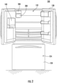
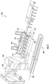
- FIG. 2 is a perspective view of refrigerator appliance 100 having refrigerator doors 128 in an open position to reveal the interior of the fresh food chamber 122 and FIG. 3 provides an exploded perspective view of an exemplary ice maker 200 of the refrigerator appliance 100.
- refrigerator appliance 100 may include an ice making assembly or icemaker 200, and an ice storage compartment 300.
- Icemaker 200 may be provided within the fresh food chamber 122 and may be ambiently exposed within the fresh food chamber. In other words, icemaker 200 is not insulated from ambient air within the fresh food chamber 122. More specifically, individual parts of icemaker 200 (which will be described below with reference to FIG. 3 ), such as a mold body 210, may be exposed within the fresh food compartment 122.
- Icemaker 200 may be in any suitable location within fresh food compartment 122 such that ice may be formed and moved into ice storage compartment 300.
- icemaker 200 is located in an upper left corner of fresh food compartment 122 when viewed from a front of refrigerator appliance 100.
- icemaker 200 may be used within any suitable refrigerator appliance, such as refrigerator appliance 100.
- icemaker 200 includes an ice mold or mold body 210 that extends between a first end portion 212 and a second end portion 214 (e.g., along a rotation axis A R ).
- Mold body 210 defines multiple compartments (e.g., one or more first compartments 216 and one or more second compartments 218) separated by one or more partitions walls for receipt of liquid water for freezing.
- the compartments 216, 218 may be spaced apart from one another or distributed (e.g., along the rotation axis A R between first end portion 212 and second end portion 214).
- a partition wall may be axially positioned between a first compartment 216 and a second compartment 218.
- icemaker 200 can receive liquid water (e.g., from a water connection to plumbing within a residence or business housing refrigerator appliance 100) and direct such liquid water into mold body 210 (e.g., into compartments 216, 218 of mold body 210). Within compartments 216, 218 of mold body 210, liquid can freeze to form ice cubes. It is understood that the term "ice cube,” as used herein, does not require a cubic geometry (i.e., six bounded square faces), but indicates a discrete unit of solid frozen ice generally having a predetermined three-dimensional shape.
- a refrigerant line or refrigerant conduit 228 may run through icemaker 200.
- refrigerant line 228 is part of a sealed system or sealed refrigerant system to be described below. Accordingly, refrigerant cooled to a temperature below freezing may be cycled through icemaker 200 to produce the ice cubes (e.g., as illustrated schematically in FIGS. 4 through 7 ).
- Icemaker 200 may further include a heating element or heater 260 mounted to a lower portion 230 of mold body 210.
- the heater 260 can be press-fit, stacked, or clamped into the lower portion 230 of the mold body 210.
- the heater 260 may heat the icemaker 200 after a harvest cycle is performed.
- the heater 260 may heat the icemaker 200 when frost is detected on the icemaker 200. In some embodiments, the heater 260 may heat the icemaker 200 during periods of non-use (e.g., when the ice storage compartment 300 is full). In some embodiments, the heater 160 may heat the icemaker 200 to assist in releasing ice cubes from the compartments 216, 218 of the mold body 210.
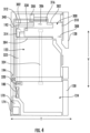
- FIG. 4 is a cut away side view of an exemplary refrigerator appliance 100.
- icemaker 200 and ice storage compartment 300 may be provided at or near a top of fresh food compartment 122 in the vertical direction V.
- icemaker 200 may be provided above ice storage compartment 300.
- ice formed in icemaker 200 may be dropped downward in the vertical direction V into ice storage compartment 300.
- the ice storage compartment 300 is provided proximal to the icemaker 200 in either or both of the transverse direction T and the lateral direction L.
- the disclosure is not limited, however, and the ice storage compartment 300 and the icemaker 200 may be located in any suitable positions.
- the ice storage compartment 300 may include a top or upper wall 302.
- the upper wall 302 may be below the icemaker 200.
- a supply opening 306 may be defined in the upper wall 302.
- the supply opening 306 is located beneath the icemaker 200.
- ice formed in the icemaker 200 may be dropped by gravity into the ice storage compartment 300.
- icemaker 200 may be positioned at other suitable locations relative to the supply opening 306 and may include additional features for dispensing ice through the supply opening, e.g., such as an auger mechanism, an ice chute, or another suitable ice transfer or conveying mechanism.
- the ice storage compartment 300 may include a bottom or lower wall 304, provided beneath the upper wall 302. Lower wall 304 may define a lower boundary of the ice storage compartment 300.
- a dispenser opening 308 may be formed in the lower wall 304 of the ice storage compartment 300. Ice cubes that are stored in the ice storage compartment 300 may be selectively released to dispenser 142 through the dispenser opening 308 according to a user input.
- a rear of the ice storage compartment 300 may be defined by a rear or side wall of the fresh food compartment 122.
- a front of the ice storage compartment 300 may be defined by one of the refrigerator doors 128. Alternatively, a separate front wall may be provided and attached to each of the upper wall 302 and the lower wall 304.
- the ice storage compartment 300 may include an insulated door 312.
- the insulated door 312 may selectively open and close the supply opening 306 in the upper wall 302.
- the insulated door 312 is attached to the ice storage compartment 300 in a sliding manner. In other words, the insulated door 312 slides in the transverse direction T to selectively open and close the supply opening 306. Alternatively, the insulated door 312 may slide in the lateral direction L to selectively open and close the supply opening 306.
- the insulated door 312 may be rotatably attached to the ice storage compartment to selectively open and close the supply opening 306.
- the insulated door 312 may be attached to the ice storage compartment 300 via a rotatable hinge.
- insulated door 312 may include one or more resilient flaps that deflect as ice is dispensed and then spring back to insulate the ice storage compartment 300 from the fresh food compartment 122.
- Other suitable means for insulating ice storage compartment 300 while also selectively permitting ice to enter ice storage compartment 300 are possible and within the scope of the present subject matter.
- the insulated door 312 may be configured to slide along an interior of the ice storage compartment 300.
- the insulated door 312 may be slidably attached to an under surface of the upper wall 302. Accordingly, when a harvest cycle is executed (e.g., when ice cubes are moved from the icemaker 200 into the ice storage compartment 300), the insulated door 312 may be slid in the transverse direction T along an interior of the ice storage compartment 300.
- the insulated door 312 may be slid in the lateral direction L when a harvest cycle is executed.
- the insulated door may be slidably provided on a top surface of upper wall 302. In other words, when a harvest cycle is executed, the insulated door 312 may be slid in the transverse direction T along a top surface of upper wall 302 to open the supply opening 306.
- the refrigerator appliance 100 may include a drive mechanism 340 configured to selectively move the insulated door 312 between an opened position and a closed position.
- the drive mechanism 340 may include a motor.
- the motor may be any suitable motor.
- the motor is a servo motor.
- the drive mechanism 340 may further include a transmission.
- the transmission may convert power generated by the motor into linear movement of the door.
- the transmission is a slide and roller combination.
- An ice storage bucket 310 may be provided in the ice storage compartment 300.
- the ice storage bucket 310 may be a separate bucket or container configured to hold the ice cubes that are formed in the icemaker 200 and dropped into ice storage compartment 300.
- the ice storage bucket 310 may be a conventional ice storage bucket.
- the ice storage bucket includes a dispenser motor 314.
- the dispenser motor 314 may drive an auger configured to selectively release ice cubes from the ice storage bucket 310 to the dispenser 142.
- Refrigerator appliance 100 may include a cooling system for maintaining a suitable temperature within ice storage compartment.
- the freezer compartment 124 may be provided below the fresh food compartment 122.
- the refrigerator appliance 100 may include a fan 320 for circulating chilled air from the freezer compartment 124 to the ice storage compartment 300.
- the fan 320 is a centrifugal fan.
- the fan 320 may be any suitable fan capable of circulating air.
- the refrigerator appliance 100 may include an air supply duct 322.
- the air supply duct 322 may fluidly connect the freezer compartment 124 with the ice storage compartment 300.
- the air supply duct 322 passes through a side wall of the cabinet 120.
- the air supply duct 322 passes through an interior of fresh food compartment 122.
- the fan 320 may be located at an inlet of the air supply duct 322 in the freezer compartment 124.
- An outlet of the air supply duct 322 may be provided at a top of the air supply duct 322.
- the outlet of the air supply duct 322 may be in fluid communication with the ice storage compartment 300. Chilled air from the freezer compartment 124 may be exhausted into the ice storage compartment 300 via the outlet of the air supply duct 322.
- the refrigerator appliance 100 may further include an air return duct 324.
- the air return duct 324 may fluidly connect the freezer compartment 124 with the ice storage compartment 300.
- the air return duct 324 passes through a side wall of the cabinet 120.
- the air return duct 324 passes through an interior of fresh food compartment 122.
- An inlet of the air return duct 324 may be provided at a top of the air return duct 324.
- the inlet of the air return duct 324 may be in fluid communication with the ice storage compartment 300.
- An outlet of the air return duct 324 may be provided at a bottom of the air return duct 324.
- the outlet of the air return duct 324 may be in fluid communication with the freezer compartment 124.
- chilled air may be circulated from the freezer compartment 124 through the air supply duct 322, into the ice storage compartment 300, through the air return duct 324, and back into the freezer compartment 124 by operation of the fan 320.
- the cooling system described above relies on forced convection through ducts that fluidly couple the ice storage compartment 300 and the freezer compartment, it should be appreciated that any other suitable system for cooling ice storage compartment may be used according to alternative embodiments.
- Refrigerator appliance 100 may further include systems for detecting a level of ice, e.g., to help determine when ice production may stop, when ice harvest may occur, etc.
- the refrigerator appliance 100 may further include a sensor 330 configured to sense a level of ice stored in the ice storage compartment 300.
- the sensor 330 may be any suitable sensor able to detect an amount of ice stored in the ice storage compartment 300, such as an optical sensor, an infrared sensor, an acoustic sensor, etc.
- the sensor 330 may be an infrared sensor.
- the sensor 330 may be provided in the ice storage compartment 300. In one example, the sensor is provided in the ice storage bucket 310 within the ice storage compartment 300.
- the sensor 330 may be operably connected to the controller 190.
- the sensor 330 may send signals relating to a level of ice within the ice storage compartment 300 to the controller 190.
- the ice level detection system is described herein as a sensor, it should be appreciated that any other suitable means for detecting ice level may be used according to alternative embodiments, such as a mechanical ice level arm.
- FIG. 5 illustrates a schematic view of a sealed refrigerant system 400 that is generally configured for executing a vapor compression cycle.
- a sealed refrigerant system, or sealed system 400 may circulate a refrigerant via a refrigerating conduit 192.
- the sealed system may include a compressor 174, a condenser 182, an expansion device 184, and an evaporator 180.
- Each of the compressor 174, condenser 182, expansion device 184, and evaporator 180 may be fluidly connected to one another by the refrigerating conduit or first refrigerating conduit 192.
- the evaporator 180 may be provided in the freezer compartment 124 and may be configured to cool air within the freezer compartment 124.
- gaseous refrigerant flows into compressor 174, which operates to increase the pressure of the refrigerant.
- This compression of the refrigerant raises its temperature, which is lowered by passing the gaseous refrigerant through condenser 182.
- condenser 182 heat exchange with ambient air takes place so as to cool the refrigerant and cause the refrigerant to condense to a liquid state.
- Expansion device 184 receives liquid refrigerant from condenser 182. From expansion device 184, the liquid refrigerant enters evaporator 180. Upon exiting expansion device 184 and entering evaporator 180, the liquid refrigerant drops in pressure and vaporizes. Due to the pressure drop and phase change of the refrigerant, evaporator 180 is cool relative to freezer compartment 124. As such, cooled water and ice or air is produced and refrigerates icemaker 200 or freezer compartment 124. Thus, evaporator 180 is a heat exchanger which transfers heat from water or air in thermal communication with evaporator 180 to refrigerant flowing through evaporator 180.
- evaporator 180 is a heat exchanger which transfers heat from water or air in thermal communication with evaporator 180 to refrigerant flowing through evaporator 180.
- the sealed refrigerant system 400 may include a three-way valve 194 operably coupled to the refrigerant conduit 192 between the evaporator 180 and the icemaker 200.
- the three-way valve 194 may be selectively opened to allow refrigerant to circulate through the icemaker 200.
- the controller 190 may control an opening and closing of the three-way valve 194 to allow the refrigerant to circulate through the icemaker 200.
- the three-way valve 194 may be any suitable valve capable of selectively opening and closing a bypass passageway 196.
- the three-way valve 194 may have one inlet and two outlets, and the controller 190 may control one outlet to be open at a time. As such, refrigerant may either circulate through the refrigerant conduit 192 or through the bypass passageway 196.
- the controller 190 may control the three-way valve 194 to close the bypass passageway 196 to allow refrigerant to circulate through the icemaker 200. In this manner, icemaker 200 is supplied with refrigerant to form ice cubes.
- the controller 190 may control the three-way valve 194 to open the bypass passageway 196 to restrict refrigerant from circulating through the icemaker 200. In this manner, no refrigerant is supplied to the icemaker 200. Consequently, because the icemaker 200 is provided in the fresh food compartment 122, which is maintained at a temperature above freezing, frost formed on an outside of the icemaker 200 may melt off, preventing malfunction or failure of the icemaker 200.
- the refrigerator appliance 100 may further include a drain pan or drain conduit 316.
- the drain conduit 316 may be provided beneath the icemaker 200 and may collect condensate or melt water from the icemaker 200. Melt water may be formed as frost on the icemaker 200 melts when the icemaker 200 is in an inactive state (e.g., no refrigerant is being cycled to the icemaker 200). In other words, when the three-way valve 194 is closed (i.e., refrigerant is circulated through the bypass passageway 196), frost on the icemaker 200 melts due to exposure to air that is above freezing within the fresh food compartment 122.
- the drain conduit 316 may be a pan located beneath the icemaker 200. The drain conduit 316 may then guide melt water to an outside of the refrigerator appliance 100 or to any other suitable collection container or reservoir.
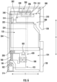
- FIG. 6 illustrates another exemplary embodiment of the refrigerator appliance 100. Due to the similarities between embodiments described herein, like reference numerals may be used to refer to the same or similar features.
- the sealed system 400 includes a first sealed system 410 and a second sealed system 420.
- the first sealed system 410 may include the compressor 174, the condenser 182, the expansion device 184, and the evaporator 180, all in fluid communication with each other through the refrigerant conduit 192.
- the operation of these elements is described above; thus, a repeat detailed description is omitted.
- the refrigerant conduit 192 may also pass through a heat exchanger 188.
- the heat exchanger 188 may be a heat exchanger configured to exchange heat between two sealed systems.
- the heat exchanger 188 is a liquid-to-liquid heat exchanger.
- the second sealed system 420 may include a pump 502 and a second refrigerant conduit 504.
- the pump 502 may be a fluid pump configured to circulate a refrigerant through the second refrigerant conduit 504.
- the second refrigerant conduit 504 may pass through the heat exchanger 188.
- the second refrigerant conduit 504 may pass through the icemaker 200.
- the second refrigerant conduit 504 may exchange heat with the first refrigerant conduit 192 within the heat exchanger 188.
- the cooled refrigerant may then be circulated through the icemaker 200 by the pump 502.
- the refrigerant circulated through second refrigerant conduit 192 may be any suitable refrigerant capable of retaining and distributing heat.
- the refrigerant circulated through the second refrigerant conduit 192 may be a water/glycol brine solution. Additionally, or alternatively, a propylene glycol, ethylene glycol, or antifreeze solution may be used.
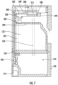
- FIG. 7 illustrates the various insulated walls, mullions, partitions, or other insulated structures within cabinet 102 of refrigerator appliance 100.
- the insulated structures are illustrated here using cross hatching.
- the ice storage compartment 300 may be located in the fresh food compartment 122 of the exemplary refrigerator appliance 100.
- the ice storage compartment 300 may be insulated from the fresh food compartment 122.
- upper wall 302 may have a first insulation 390.
- First insulation 390 may be an insulated coating provided over the upper wall 302.
- the upper wall 302 may be coated in a foam insulation spray.
- the upper wall 302 may define an inner volume filled with insulation.
- Second insulation 392 may be an insulated coating provided over the lower wall 304.
- the lower wall 304 may be coated in a foam insulation spray.
- the lower wall 304 may define an inner volume filled with insulation.
- the insulated door 312 may have a third insulation 394.
- Third insulation 394 may be an insulated coating provided over the insulated door 312.
- the insulated door 312 may be coated in a foam insulation spray.
- the insulated door 312 may define an inner volume filled with insulation.
- the sealed system 400 may be operated by driving the compressor 174 to circulate a refrigerant through the icemaker 200.
- the three-way valve 194 is in an open position (e.g., the bypass passageway 196 is closed).
- the controller 190 may activate the drive mechanism 340 to open the insulated door 312. Once the insulated door 312 is in the opened position, the ice cubes may be harvested from the icemaker 200 (e.g., the ice cubes are dropped into the ice storage compartment 300 through the supply opening 306).
- the controller 190 may turn off the fan 320. Accordingly, cool air from the freezer compartment 124 may not be supplied to the ice storage compartment 300 during a harvesting of the ice cubes. This prevents an unwanted cooling of the fresh food compartment 122 when the insulated door 312 is in the opened position. Simultaneously, the controller 190 may switch the three-way valve 194 to a closed position (e.g., the bypass passageway 196 is opened). Thus, the refrigerant may not be circulated through the icemaker 200 during a harvesting of the ice cubes. This prevents frost from forming on the icemaker 200 due to sublimation of moisture from the ice cubes and/or cool air within the ice storage compartment 300.
- the controller 190 may activate the drive mechanism to move the insulated door 312 to the closed position (e.g., close the supply opening 306).
- the controller 190 may then switch the three-way valve 194 to the open position (e.g., close the bypass passageway 196). Accordingly, refrigerant may flow through the icemaker 200 to reinstitute an icemaking operation.
- Sensor 330 may then sense an amount of ice in the ice storage compartment 300.
- the controller 190 may switch the three-way valve to the closed position (e.g., open the bypass passageway 196).
- the first predetermined amount may signify that the ice storage compartment 300 is substantially full.
- refrigerant is not circulated through the icemaker 200. Accordingly, frost accumulated on the icemaker 200 may be melted due to a position of the icemaker 200 in the fresh food compartment 122 and subsequent exposure to an above freezing atmosphere.
- the controller 190 may switch the pump 502 to an off position.
- refrigerant in the second refrigerant conduit 504 may be prevented from circulating through icemaker 200. Accordingly, frost accumulated on the icemaker 200 may be melted due to a position of the icemaker 200 in the fresh food compartment 122 and subsequent exposure to an above freezing atmosphere.
- the sensor 330 may continue to sense an amount of ice in the ice storage compartment 300.
- the controller 190 may switch the three-way valve 194 to the open position (e.g., close the bypass passageway 196).
- the second predetermined level may signify that the ice storage compartment 300 is approximately half full.
- the first predetermined level and the second predetermined level may be the same.
- refrigerant may be circulated through the icemaker 200 to again reinstitute the icemaking operation. The method may be repeated as necessary to maintain a usable amount of ice in the ice storage compartment 300.
- the controller 190 may switch the pump 502 to an on position.
- refrigerant in the second refrigerant conduit 504 may be circulated through the icemaker 200 to again reinstitute the icemaking operation. The method may be repeated as necessary to maintain a usable amount of ice in the ice storage compartment 300.
- the refrigerator appliance 100 may be one of the exemplary refrigerator appliances described above, and as such, a detailed description will be omitted.
- the method 500 includes operating the sealed refrigerant system 400 to cool the icemaker 200 and form ice.
- the operation of the sealed refrigerant system 400 includes operating the compressor 174 to circulate a refrigerant.
- three-way valve 194 is in the open position (e.g., refrigerant is circulating through icemaker 200).
- the method 500 includes determining that ice is ready to be harvested from the icemaker 200.
- the controller 190 may determine that ice cubes have been formed and sufficiently frozen within icemaker 200 such that they may be moved or dropped into the ice storage compartment 300.
- the controller 190 may use a variety of means to determine that the ice is ready to be harvested, such as a timer or a sensor.
- the method 500 may proceed to 530.
- the method 500 turns off the fan 320 and closes the three-way valve 194 (e.g., refrigerant is not circulating through icemaker 200).
- the controller 190 may send a signal to stop the fan 320 from circulating air from freezing compartment 124 into ice storage compartment 300.
- cool air from freezing compartment 124 is not supplied to ice storage compartment 300.
- the controller 190 may activate the three-way valve 194 to stop a flow of the refrigerant to the icemaker 200.
- icemaker 200 is not cooled while the ice is ejected from the icemaker 200 into the ice storage compartment 300.
- the method 500 opens the insulated door 312.
- the controller 190 may send a signal to drive mechanism 340 to move the insulated door 312 from a closed position to an open position.
- an interior of ice storage compartment 300 is exposed to the fresh food compartment 122 such that the ice cubes may be dropped into the ice storage compartment 300.
- ice is then harvested from icemaker 200 and dropped into ice storage compartment 300.
- the method 500 includes determining whether the harvesting is complete.
- the refrigerator appliance 100 may include sensors configured to detect whether the harvesting is complete, such as rotation sensors or infrared sensors on the icemaker 200. Is the harvesting is determined to be complete, the method 500 moves to 570.
- the method 500 includes determining if an amount of ice in the ice storage compartment 300 is above a predetermined amount.
- the method 500 may refer to sensor 330 described above to determine an amount of ice in the ice storage compartment 300. If the amount is above the predetermined amount, the method 500 proceeds to 580.
- the method 500 includes closing the insulated door 312, switching the fan 320 to the on state, and maintaining the three-way valve 194 in the closed state. As such, the icemaker 200 is not supplied with refrigerant and thus may defrost. Further, cool air is supplied to the ice storage compartment 300 to maintain the ice in a frozen state. If the amount is below the predetermined amount, the method 500 proceeds to 590.
- the method 500 includes closing insulated door 312 and opening three-way valve 194. Once insulated door 312 is closed and three-way valve 194 is opened, an icemaking operation may begin again. The method 500 may be repeated as necessary to continually make and harvest ice up to the predetermined amount. Further, sensor 330 may continually determine an amount of ice in ice storage compartment 300 to determine whether or not to open three-way valve 194 to circulate refrigerant to icemaker 200 and perform the icemaking operation.
- the placement of icemaker 200 within the fresh food compartment may eliminate the need for a water fill tube heater to heat a water fill tube that supplies water to mold body 210. Accordingly, energy and electricity use may be reduced, as well as complexity of manufacturing and amount of parts.
Landscapes
- Engineering & Computer Science (AREA)
- Physics & Mathematics (AREA)
- Mechanical Engineering (AREA)
- Thermal Sciences (AREA)
- General Engineering & Computer Science (AREA)
- Chemical & Material Sciences (AREA)
- Combustion & Propulsion (AREA)
- Devices That Are Associated With Refrigeration Equipment (AREA)
- Production, Working, Storing, Or Distribution Of Ice (AREA)
- Confectionery (AREA)
Abstract
Description
- The present subject matter relates generally to refrigerator appliances, and more particularly to refrigerator appliances having ice makers and ice storage bins.
- Refrigerator appliances generally include a cabinet that defines one or more chilled chambers for receipt of food articles for storage. In addition, refrigerator appliances also generally include a door rotatably hinged to the cabinet to permit selective access to food items stored in chilled chamber(s). Certain refrigerator appliances include an icemaker. In order to produce ice, liquid water is directed to the icemaker and frozen. After being frozen, ice may be directed to a separate ice storage bin. In order to maintain ice in a frozen state, the icemaker and the ice storage bin may be positioned within a chilled chambers maintained at a temperature below the freezing point of water, e.g., such as in the freezer chamber or in a separate compartment behind one of the doors.
- Conventional icemakers are positioned within a freezer chamber that has a temperature below the freezing point of water, e.g., such that cool air within the freezer chamber can freeze water dispensed into a plurality of ice molds and facilitate the ice making process. However, a common problem with such icemakers is ice buildup. For example, since the icemaker is much colder than the ice, moisture commonly sublimates from the ice and transfers to the icemaker mold. This develops ice buildup or frost on the icemaker. Ice buildup may require costly heating systems required to remove the ice buildup and may result in dispensing failures. Further, conventional icemakers require a water fill tube heater in order to prevent water within the water fill tube from freezing and clogging, potentially damaging the water fill tube or water supply system.
- Accordingly, it would be advantageous to provide a refrigerator appliance with an improved ice making assembly that reduces frost buildup and includes feature(s) addressing one or more of the above identified issues.
- Aspects and advantages of the invention will be set forth in part in the following description, or may be obvious from the description, or may be learned through practice of the invention.
- In one exemplary aspect of the present disclosure, a refrigerator appliance is provided. The refrigerator may include a fresh food compartment. An ice storage bucket may be positioned within the fresh food compartment and may be insulated from the fresh food compartment. A sealed system including a condenser, an expansion device, and an evaporator may be fluidly coupled through a refrigerant conduit, and a compressor may be operably coupled to the refrigerant conduit for circulating a flow of refrigerant through the refrigerant conduit. An icemaker may be positioned within the fresh food compartment above the ice storage bucket and may include an ice mold for receiving water to freeze into ice cubes. The sealed system may be in direct thermal communication with the ice mold. An insulated door may be positioned over an opening in the ice storage compartment, and the insulated door may be movable between an opened and closed position to permit ice to pass into the ice storage compartment.
- In another exemplary aspect of the present disclosure, a refrigerator appliance is provided. The refrigerator may include a fresh food compartment and a freezing compartment adjacent to the fresh food compartment. A first sealed refrigerant system may include a compressor, a condenser, an evaporator, an expansion device, and a first liquid-to-liquid heat exchanger on a first refrigerant line and may circulate a first refrigerant through the first refrigerant line. A second sealed refrigerant system may include a second liquid-to-liquid heat exchanger and a pump on a second refrigerant line and heat may be transferred between the first and second liquid-to-liquid heat exchangers to directly cool the ice maker. An icemaker may be positioned within the fresh food compartment and may include an ice mold for receiving water to freeze into ice cubes. The second refrigerant line may pass through the icemaker. An ice storage compartment may be positioned below the icemaker and may be insulated from the fresh food compartment. An insulated door may be positioned over an opening in the ice storage compartment and may be movable between an open and a closed position to permit ice to pass from the icemaker into the ice storage compartment. A controller may control the icemaker, the first sealed refrigerant system, the second sealed refrigerant system, and the insulated door.
- In still another exemplary aspect of the present disclosure, a method of operating a refrigerator appliance is provided. The method may include operating a sealed system to cool an icemaker and form ice, determining that ice is ready to be harvested from the icemaker, opening an insulated door of an ice storage compartment, and ejecting the ice from the icemaker such that the ice passes from the icemaker to the ice storage compartment.
- These and other features, aspects and advantages of the present invention will become better understood with reference to the following description and appended claims. The accompanying drawings, which are incorporated in and constitute a part of this specification, illustrate embodiments of the invention and, together with the description, serve to explain the principles of the invention.
- A full and enabling disclosure of the present invention, including the best mode thereof, directed to one of ordinary skill in the art, is set forth in the specification, which makes reference to the appended figures.
-
FIG. 1 provides a perspective view of a refrigerator appliance according to an exemplary embodiment of the present disclosure, wherein refrigerator doors are shown in a closed position. -
FIG. 2 provides a front view of the exemplary refrigerator appliance ofFIG. 1 , where in refrigerator doors are shown in an open position. -
FIG. 3 provides an exploded perspective view of an icemaker of the exemplary refrigerator appliance ofFIG. 1 . -
FIG. 4 provides a side cross-sectional view of the exemplary refrigerator appliance ofFIG. 1 . -
FIG. 5 provides a schematic view of a sealed refrigerant system according to the exemplary refrigerator appliance ofFIG. 1 . -
FIG. 6 provides a side cross-sectional view of another exemplary embodiment of the refrigerator appliance. -
FIG. 7 provides a side cross-sectional view of an exemplary refrigerator appliance with an insulated door in a closed position. - Reference now will be made in detail to embodiments of the invention, one or more examples of which are illustrated in the drawings. Each example is provided by way of explanation of the invention, not limitation of the invention. In fact, it will be apparent to those skilled in the art that various modifications and variations can be made in the present invention without departing from the scope of the invention. For instance, features illustrated or described as part of one embodiment can be used with another embodiment to yield a still further embodiment. Thus, it is intended that the present invention covers such modifications and variations as come within the scope of the appended claims and their equivalents.
- As used herein, the term "or" is generally intended to be inclusive (i.e., "A or B" is intended to mean "A or B or both"). The terms "first," "second," and "third" may be used interchangeably to distinguish one component from another and are not intended to signify location or importance of the individual components. The terms "upstream" and "downstream" refer to the relative flow direction with respect to fluid flow in a fluid pathway. For example, "upstream" refers to the flow direction from which the fluid flows, and "downstream" refers to the flow direction to which the fluid flows.
- Referring now to the drawings,
FIG. 1 provides a pair ofrefrigerator doors 128 in a closed position.Refrigerator appliance 100 includes a cabinet orhousing 120 that extends between atop 101 and abottom 102 along a verticaldirection V. Cabinet 120 also extends along a lateral direction L and a transverse direction T, each of the vertical direction V, lateral direction L, and transverse direction T being mutually perpendicular to one another.Cabinet 120 defines one or more chilled chambers for receipt of food items for storage. In some embodiments,cabinet 120 defines a fresh food chamber orcompartment 122 positioned at oradjacent top 101 ofcabinet 120 and a freezer chamber orcompartment 124 arranged at oradjacent bottom 102 ofcabinet 120. As such,refrigerator appliance 100 is generally referred to as a bottom mount refrigerator. It is recognized, however, that the benefits of the present disclosure apply to other types and styles of refrigerator appliances such as, for example, a top mount refrigerator appliance or a side-by-side style refrigerator appliance. Consequently, the description set forth herein is for illustrative purposes only and is not intended to be limiting in any aspect to any particular refrigerator chamber configuration. -
Refrigerator doors 128 are rotatably hinged to an edge ofcabinet 120 for selectively accessingfresh food chamber 122. In some embodiments, afreezer door 130 is arranged belowrefrigerator doors 128 for selectively accessingfreezer compartment 124.Freezer door 130 may be coupled to a freezer drawer (not shown) slidably mounted withinfreezer compartment 124.Refrigerator doors 128 andfreezer door 130 are shown in the closed configuration inFIG. 1 . - In some embodiments,
refrigerator appliance 100 includes a dispensingassembly 140 for dispensing liquid water or ice.Dispensing assembly 140 includes adispenser 142 positioned on or mounted to an exterior portion of refrigerator appliance 100 (e.g., on one of doors 128).Dispenser 142 includes a dischargingoutlet 144 for accessing ice and liquid water. Anactuating mechanism 146, shown as a paddle, is mounted below dischargingoutlet 144 for operatingdispenser 142. In alternative exemplary embodiments, another suitable actuator may be used to operatedispenser 142. For example,dispenser 142 can include a sensor (such as an ultrasonic sensor) or a button rather than the paddle. Auser interface panel 148 is provided for controlling the mode of operation. For example,user interface panel 148 includes a plurality of user inputs (not labeled), such as a water dispensing button and an ice-dispensing button, for selecting a desired mode of operation such as crushed or non-crushed ice. - Discharging
outlet 144 andactuating mechanism 146 are an external part ofdispenser 142 and are mounted in adispenser recess 150, as will be described in greater detail below. Generally,dispenser recess 150 defines atransverse opening 151 that extends in the vertical direction V from atop recess end 152 to abottom recess end 154, as well as in the lateral direction L from afirst recess side 156 to asecond recess side 158. In certain embodiments,dispenser recess 150 is positioned at a predetermined elevation convenient for a user to access ice or water and enabling the user to access ice without the need to bend-over and without the need to opendoors 128. In optional embodiments,dispenser recess 150 is positioned at a level that approximates the chest level of a user. - Generally, operation of the
refrigerator appliance 100 can be regulated by acontroller 190 that is operatively coupled touser interface panel 148 or various other components, as will be described below.User interface panel 148 provides selections for user manipulation of the operation ofrefrigerator appliance 100, such as selections between whole or crushed ice, chilled water, or other various options. In response to user manipulation ofuser interface panel 148 or one or more sensor signals,controller 190 may operate various components of therefrigerator appliance 100.Controller 190 may include a memory and one or more microprocessors, CPUs or the like, such as general or special purpose microprocessors operable to execute programming instructions or micro-control code associated with operation ofrefrigerator appliance 100. The memory may represent random access memory such as DRAM, or read only memory such as ROM or FLASH. In one embodiment, the processor executes programming instructions stored in memory. The memory may be a separate component from the processor or may be included onboard within the processor. Alternatively,controller 190 may be constructed without using a microprocessor (e.g., using a combination of discrete analog or digital logic circuitry-such as switches, amplifiers, integrators, comparators, flip-flops, AND gates, and the like) to perform control functionality instead of relying upon software. -
Controller 190 may be positioned in a variety of locations throughoutrefrigerator appliance 100. In the illustrated embodiment,controller 190 is located adjacent to or onuser interface panel 148. In other embodiments,controller 190 may be positioned at another suitable location withinrefrigerator appliance 100, such as for example within a fresh food chamber, a freezer door, etc. Input/output ("I/O") signals may be routed betweencontroller 190 and various operational components ofrefrigerator appliance 100. For example,user interface panel 148 may be in operable communication (e.g., electrical communication) withcontroller 190 via one or more signal lines or shared communication busses. -
Controller 190 may be operatively coupled with the various components of dispensingassembly 140 and may control operation of the various components. For example, the various valves, switches, etc. may be actuatable based on commands fromcontroller 190. As discussed,interface panel 148 may additionally be operatively coupled (e.g., via electrical or wireless communication) withcontroller 190. Thus, the various operations may occur based on user input or automatically throughcontroller 190 instruction. -
FIG. 2 is a perspective view ofrefrigerator appliance 100 havingrefrigerator doors 128 in an open position to reveal the interior of thefresh food chamber 122 andFIG. 3 provides an exploded perspective view of anexemplary ice maker 200 of therefrigerator appliance 100. As illustrated,refrigerator appliance 100 may include an ice making assembly oricemaker 200, and anice storage compartment 300.Icemaker 200 may be provided within thefresh food chamber 122 and may be ambiently exposed within the fresh food chamber. In other words,icemaker 200 is not insulated from ambient air within thefresh food chamber 122. More specifically, individual parts of icemaker 200 (which will be described below with reference toFIG. 3 ), such as amold body 210, may be exposed within thefresh food compartment 122.Icemaker 200 may be in any suitable location withinfresh food compartment 122 such that ice may be formed and moved intoice storage compartment 300. In one example,icemaker 200 is located in an upper left corner offresh food compartment 122 when viewed from a front ofrefrigerator appliance 100. As is understood,icemaker 200 may be used within any suitable refrigerator appliance, such asrefrigerator appliance 100. - Generally,
icemaker 200 includes an ice mold ormold body 210 that extends between afirst end portion 212 and a second end portion 214 (e.g., along a rotation axis AR).Mold body 210 defines multiple compartments (e.g., one or morefirst compartments 216 and one or more second compartments 218) separated by one or more partitions walls for receipt of liquid water for freezing. Thecompartments first end portion 212 and second end portion 214). Thus, a partition wall may be axially positioned between afirst compartment 216 and asecond compartment 218. - Generally,
icemaker 200 can receive liquid water (e.g., from a water connection to plumbing within a residence or business housing refrigerator appliance 100) and direct such liquid water into mold body 210 (e.g., intocompartments compartments mold body 210, liquid can freeze to form ice cubes. It is understood that the term "ice cube," as used herein, does not require a cubic geometry (i.e., six bounded square faces), but indicates a discrete unit of solid frozen ice generally having a predetermined three-dimensional shape. - As shown, a refrigerant line or
refrigerant conduit 228 may run throughicemaker 200. For example,refrigerant line 228 is part of a sealed system or sealed refrigerant system to be described below. Accordingly, refrigerant cooled to a temperature below freezing may be cycled throughicemaker 200 to produce the ice cubes (e.g., as illustrated schematically inFIGS. 4 through 7 ).Icemaker 200 may further include a heating element orheater 260 mounted to alower portion 230 ofmold body 210. Theheater 260 can be press-fit, stacked, or clamped into thelower portion 230 of themold body 210. Theheater 260 may heat theicemaker 200 after a harvest cycle is performed. Alternatively, theheater 260 may heat theicemaker 200 when frost is detected on theicemaker 200. In some embodiments, theheater 260 may heat theicemaker 200 during periods of non-use (e.g., when theice storage compartment 300 is full). In some embodiments, the heater 160 may heat theicemaker 200 to assist in releasing ice cubes from thecompartments mold body 210. -
FIG. 4 is a cut away side view of anexemplary refrigerator appliance 100. As seen inFIG. 4 ,icemaker 200 andice storage compartment 300 may be provided at or near a top offresh food compartment 122 in the vertical direction V. Specifically,icemaker 200 may be provided aboveice storage compartment 300. As such, ice formed inicemaker 200 may be dropped downward in the vertical direction V intoice storage compartment 300. In some embodiments, theice storage compartment 300 is provided proximal to theicemaker 200 in either or both of the transverse direction T and the lateral direction L. The disclosure is not limited, however, and theice storage compartment 300 and theicemaker 200 may be located in any suitable positions. - The
ice storage compartment 300 may include a top orupper wall 302. Theupper wall 302 may be below theicemaker 200. Asupply opening 306 may be defined in theupper wall 302. In some embodiments, thesupply opening 306 is located beneath theicemaker 200. As such, ice formed in theicemaker 200 may be dropped by gravity into theice storage compartment 300. According to alternative exemplary embodiments,icemaker 200 may be positioned at other suitable locations relative to thesupply opening 306 and may include additional features for dispensing ice through the supply opening, e.g., such as an auger mechanism, an ice chute, or another suitable ice transfer or conveying mechanism. - The
ice storage compartment 300 may include a bottom orlower wall 304, provided beneath theupper wall 302.Lower wall 304 may define a lower boundary of theice storage compartment 300. Adispenser opening 308 may be formed in thelower wall 304 of theice storage compartment 300. Ice cubes that are stored in theice storage compartment 300 may be selectively released todispenser 142 through thedispenser opening 308 according to a user input. A rear of theice storage compartment 300 may be defined by a rear or side wall of thefresh food compartment 122. A front of theice storage compartment 300 may be defined by one of therefrigerator doors 128. Alternatively, a separate front wall may be provided and attached to each of theupper wall 302 and thelower wall 304. - The
ice storage compartment 300 may include aninsulated door 312. Theinsulated door 312 may selectively open and close thesupply opening 306 in theupper wall 302. In some embodiments, theinsulated door 312 is attached to theice storage compartment 300 in a sliding manner. In other words, theinsulated door 312 slides in the transverse direction T to selectively open and close thesupply opening 306. Alternatively, theinsulated door 312 may slide in the lateral direction L to selectively open and close thesupply opening 306. In alternate embodiments, theinsulated door 312 may be rotatably attached to the ice storage compartment to selectively open and close thesupply opening 306. For example, theinsulated door 312 may be attached to theice storage compartment 300 via a rotatable hinge. According to still other exemplary embodiments, insulateddoor 312 may include one or more resilient flaps that deflect as ice is dispensed and then spring back to insulate theice storage compartment 300 from thefresh food compartment 122. Other suitable means for insulatingice storage compartment 300 while also selectively permitting ice to enterice storage compartment 300 are possible and within the scope of the present subject matter. - The
insulated door 312 may be configured to slide along an interior of theice storage compartment 300. In other words, theinsulated door 312 may be slidably attached to an under surface of theupper wall 302. Accordingly, when a harvest cycle is executed (e.g., when ice cubes are moved from theicemaker 200 into the ice storage compartment 300), theinsulated door 312 may be slid in the transverse direction T along an interior of theice storage compartment 300. In some embodiments, theinsulated door 312 may be slid in the lateral direction L when a harvest cycle is executed. In still other embodiments, the insulated door may be slidably provided on a top surface ofupper wall 302. In other words, when a harvest cycle is executed, theinsulated door 312 may be slid in the transverse direction T along a top surface ofupper wall 302 to open thesupply opening 306. - The
refrigerator appliance 100 may include adrive mechanism 340 configured to selectively move theinsulated door 312 between an opened position and a closed position. Thedrive mechanism 340 may include a motor. The motor may be any suitable motor. In one example, the motor is a servo motor. Thedrive mechanism 340 may further include a transmission. The transmission may convert power generated by the motor into linear movement of the door. In one example, the transmission is a slide and roller combination. - An
ice storage bucket 310 may be provided in theice storage compartment 300. Theice storage bucket 310 may be a separate bucket or container configured to hold the ice cubes that are formed in theicemaker 200 and dropped intoice storage compartment 300. Theice storage bucket 310 may be a conventional ice storage bucket. For example, the ice storage bucket includes adispenser motor 314. Thedispenser motor 314 may drive an auger configured to selectively release ice cubes from theice storage bucket 310 to thedispenser 142. -
Refrigerator appliance 100 may include a cooling system for maintaining a suitable temperature within ice storage compartment. For example, according to an exemplary embodiment of therefrigerator appliance 100, thefreezer compartment 124 may be provided below thefresh food compartment 122. In order to supply chilled air to theice storage compartment 300, therefrigerator appliance 100 according to the exemplary embodiment may include afan 320 for circulating chilled air from thefreezer compartment 124 to theice storage compartment 300. In one example, thefan 320 is a centrifugal fan. However, thefan 320 may be any suitable fan capable of circulating air. Therefrigerator appliance 100 may include anair supply duct 322. Theair supply duct 322 may fluidly connect thefreezer compartment 124 with theice storage compartment 300. For example, theair supply duct 322 passes through a side wall of thecabinet 120. In alternative embodiments, theair supply duct 322 passes through an interior offresh food compartment 122. Thefan 320 may be located at an inlet of theair supply duct 322 in thefreezer compartment 124. An outlet of theair supply duct 322 may be provided at a top of theair supply duct 322. The outlet of theair supply duct 322 may be in fluid communication with theice storage compartment 300. Chilled air from thefreezer compartment 124 may be exhausted into theice storage compartment 300 via the outlet of theair supply duct 322. - The
refrigerator appliance 100 according to an exemplary embodiment may further include anair return duct 324. Theair return duct 324 may fluidly connect thefreezer compartment 124 with theice storage compartment 300. For example, theair return duct 324 passes through a side wall of thecabinet 120. In alternative embodiments, theair return duct 324 passes through an interior offresh food compartment 122. An inlet of theair return duct 324 may be provided at a top of theair return duct 324. The inlet of theair return duct 324 may be in fluid communication with theice storage compartment 300. An outlet of theair return duct 324 may be provided at a bottom of theair return duct 324. The outlet of theair return duct 324 may be in fluid communication with thefreezer compartment 124. Thus, chilled air may be circulated from thefreezer compartment 124 through theair supply duct 322, into theice storage compartment 300, through theair return duct 324, and back into thefreezer compartment 124 by operation of thefan 320. Although the cooling system described above relies on forced convection through ducts that fluidly couple theice storage compartment 300 and the freezer compartment, it should be appreciated that any other suitable system for cooling ice storage compartment may be used according to alternative embodiments. -
Refrigerator appliance 100 may further include systems for detecting a level of ice, e.g., to help determine when ice production may stop, when ice harvest may occur, etc. For example, therefrigerator appliance 100 according to an exemplary embodiment may further include asensor 330 configured to sense a level of ice stored in theice storage compartment 300. Thesensor 330 may be any suitable sensor able to detect an amount of ice stored in theice storage compartment 300, such as an optical sensor, an infrared sensor, an acoustic sensor, etc. For example, thesensor 330 may be an infrared sensor. Thesensor 330 may be provided in theice storage compartment 300. In one example, the sensor is provided in theice storage bucket 310 within theice storage compartment 300. Thesensor 330 may be operably connected to thecontroller 190. Thesensor 330 may send signals relating to a level of ice within theice storage compartment 300 to thecontroller 190. Although the ice level detection system is described herein as a sensor, it should be appreciated that any other suitable means for detecting ice level may be used according to alternative embodiments, such as a mechanical ice level arm. -
FIG. 5 illustrates a schematic view of a sealedrefrigerant system 400 that is generally configured for executing a vapor compression cycle. According toFIG. 5 , a sealed refrigerant system, or sealedsystem 400 may circulate a refrigerant via a refrigeratingconduit 192. The sealed system may include acompressor 174, acondenser 182, anexpansion device 184, and anevaporator 180. Each of thecompressor 174,condenser 182,expansion device 184, andevaporator 180 may be fluidly connected to one another by the refrigerating conduit or first refrigeratingconduit 192. Theevaporator 180 may be provided in thefreezer compartment 124 and may be configured to cool air within thefreezer compartment 124. - Within sealed
system 400, gaseous refrigerant flows intocompressor 174, which operates to increase the pressure of the refrigerant. This compression of the refrigerant raises its temperature, which is lowered by passing the gaseous refrigerant throughcondenser 182. Withincondenser 182, heat exchange with ambient air takes place so as to cool the refrigerant and cause the refrigerant to condense to a liquid state. - Expansion device 184 (e.g., a mechanical valve, capillary tube, electronic expansion valve, or other restriction device) receives liquid refrigerant from
condenser 182. Fromexpansion device 184, the liquid refrigerant entersevaporator 180. Upon exitingexpansion device 184 and enteringevaporator 180, the liquid refrigerant drops in pressure and vaporizes. Due to the pressure drop and phase change of the refrigerant,evaporator 180 is cool relative tofreezer compartment 124. As such, cooled water and ice or air is produced and refrigeratesicemaker 200 orfreezer compartment 124. Thus,evaporator 180 is a heat exchanger which transfers heat from water or air in thermal communication withevaporator 180 to refrigerant flowing throughevaporator 180. - The sealed
refrigerant system 400 may include a three-way valve 194 operably coupled to therefrigerant conduit 192 between theevaporator 180 and theicemaker 200. The three-way valve 194 may be selectively opened to allow refrigerant to circulate through theicemaker 200. Thecontroller 190 may control an opening and closing of the three-way valve 194 to allow the refrigerant to circulate through theicemaker 200. The three-way valve 194 may be any suitable valve capable of selectively opening and closing abypass passageway 196. For example, the three-way valve 194 may have one inlet and two outlets, and thecontroller 190 may control one outlet to be open at a time. As such, refrigerant may either circulate through therefrigerant conduit 192 or through thebypass passageway 196. - According to one example, the
controller 190 may control the three-way valve 194 to close thebypass passageway 196 to allow refrigerant to circulate through theicemaker 200. In this manner,icemaker 200 is supplied with refrigerant to form ice cubes. According to another example, thecontroller 190 may control the three-way valve 194 to open thebypass passageway 196 to restrict refrigerant from circulating through theicemaker 200. In this manner, no refrigerant is supplied to theicemaker 200. Consequently, because theicemaker 200 is provided in thefresh food compartment 122, which is maintained at a temperature above freezing, frost formed on an outside of theicemaker 200 may melt off, preventing malfunction or failure of theicemaker 200. - The
refrigerator appliance 100 according to an exemplary embodiment may further include a drain pan ordrain conduit 316. Thedrain conduit 316 may be provided beneath theicemaker 200 and may collect condensate or melt water from theicemaker 200. Melt water may be formed as frost on theicemaker 200 melts when theicemaker 200 is in an inactive state (e.g., no refrigerant is being cycled to the icemaker 200). In other words, when the three-way valve 194 is closed (i.e., refrigerant is circulated through the bypass passageway 196), frost on theicemaker 200 melts due to exposure to air that is above freezing within thefresh food compartment 122. Thedrain conduit 316 may be a pan located beneath theicemaker 200. Thedrain conduit 316 may then guide melt water to an outside of therefrigerator appliance 100 or to any other suitable collection container or reservoir. -
FIG. 6 illustrates another exemplary embodiment of therefrigerator appliance 100. Due to the similarities between embodiments described herein, like reference numerals may be used to refer to the same or similar features. According to this embodiment, the sealedsystem 400 includes a first sealedsystem 410 and a second sealedsystem 420. The first sealedsystem 410 may include thecompressor 174, thecondenser 182, theexpansion device 184, and theevaporator 180, all in fluid communication with each other through therefrigerant conduit 192. The operation of these elements is described above; thus, a repeat detailed description is omitted. Therefrigerant conduit 192 may also pass through aheat exchanger 188. Theheat exchanger 188 may be a heat exchanger configured to exchange heat between two sealed systems. For example, theheat exchanger 188 is a liquid-to-liquid heat exchanger. - The second sealed
system 420 may include apump 502 and a secondrefrigerant conduit 504. Thepump 502 may be a fluid pump configured to circulate a refrigerant through the secondrefrigerant conduit 504. The secondrefrigerant conduit 504 may pass through theheat exchanger 188. The secondrefrigerant conduit 504 may pass through theicemaker 200. The secondrefrigerant conduit 504 may exchange heat with the firstrefrigerant conduit 192 within theheat exchanger 188. The cooled refrigerant may then be circulated through theicemaker 200 by thepump 502. The refrigerant circulated through secondrefrigerant conduit 192 may be any suitable refrigerant capable of retaining and distributing heat. For example, the refrigerant circulated through the secondrefrigerant conduit 192 may be a water/glycol brine solution. Additionally, or alternatively, a propylene glycol, ethylene glycol, or antifreeze solution may be used. -
FIG. 7 illustrates the various insulated walls, mullions, partitions, or other insulated structures withincabinet 102 ofrefrigerator appliance 100. For clarity, the insulated structures are illustrated here using cross hatching. Specifically, as illustrated, theice storage compartment 300 may be located in thefresh food compartment 122 of theexemplary refrigerator appliance 100. Theice storage compartment 300 may be insulated from thefresh food compartment 122. For instance,upper wall 302 may have afirst insulation 390.First insulation 390 may be an insulated coating provided over theupper wall 302. In one example, theupper wall 302 may be coated in a foam insulation spray. In another example, theupper wall 302 may define an inner volume filled with insulation. - Similarly, the
lower wall 304 may have asecond insulation 392.Second insulation 392 may be an insulated coating provided over thelower wall 304. In one example, thelower wall 304 may be coated in a foam insulation spray. In another example, thelower wall 304 may define an inner volume filled with insulation. Theinsulated door 312 may have athird insulation 394.Third insulation 394 may be an insulated coating provided over theinsulated door 312. In one example, theinsulated door 312 may be coated in a foam insulation spray. In another example, theinsulated door 312 may define an inner volume filled with insulation. - Referring to
FIGS. 1 through 7 , a method of operating anexemplary refrigerator appliance 100 will be described. The sealedsystem 400 may be operated by driving thecompressor 174 to circulate a refrigerant through theicemaker 200. At this time, the three-way valve 194 is in an open position (e.g., thebypass passageway 196 is closed). As the chilled refrigerant is circulated through theicemaker 200, ice cubes may be formed inicemaker 200. Once thecontroller 190 determines that the ice cubes have been formed and that a harvest cycle is ready to be performed, thecontroller 190 may activate thedrive mechanism 340 to open theinsulated door 312. Once theinsulated door 312 is in the opened position, the ice cubes may be harvested from the icemaker 200 (e.g., the ice cubes are dropped into theice storage compartment 300 through the supply opening 306). - While the ice cubes are being harvested from the
icemaker 200, thecontroller 190 may turn off thefan 320. Accordingly, cool air from thefreezer compartment 124 may not be supplied to theice storage compartment 300 during a harvesting of the ice cubes. This prevents an unwanted cooling of thefresh food compartment 122 when theinsulated door 312 is in the opened position. Simultaneously, thecontroller 190 may switch the three-way valve 194 to a closed position (e.g., thebypass passageway 196 is opened). Thus, the refrigerant may not be circulated through theicemaker 200 during a harvesting of the ice cubes. This prevents frost from forming on theicemaker 200 due to sublimation of moisture from the ice cubes and/or cool air within theice storage compartment 300. - After the ice cubes have been harvested (e.g., moved from the
icemaker 200 to the ice storage compartment 300), thecontroller 190 may activate the drive mechanism to move theinsulated door 312 to the closed position (e.g., close the supply opening 306). Thecontroller 190 may then switch the three-way valve 194 to the open position (e.g., close the bypass passageway 196). Accordingly, refrigerant may flow through theicemaker 200 to reinstitute an icemaking operation.Sensor 330 may then sense an amount of ice in theice storage compartment 300. When thesensor 330 senses that an amount of ice is above a first predetermined amount, thecontroller 190 may switch the three-way valve to the closed position (e.g., open the bypass passageway 196). The first predetermined amount may signify that theice storage compartment 300 is substantially full. Thus, refrigerant is not circulated through theicemaker 200. Accordingly, frost accumulated on theicemaker 200 may be melted due to a position of theicemaker 200 in thefresh food compartment 122 and subsequent exposure to an above freezing atmosphere. - According to some embodiments, when the
sensor 330 senses that an amount of ice is above the first predetermined amount, thecontroller 190 may switch thepump 502 to an off position. Thus, refrigerant in the secondrefrigerant conduit 504 may be prevented from circulating throughicemaker 200. Accordingly, frost accumulated on theicemaker 200 may be melted due to a position of theicemaker 200 in thefresh food compartment 122 and subsequent exposure to an above freezing atmosphere. - The
sensor 330 may continue to sense an amount of ice in theice storage compartment 300. When the level of ice sensed by thesensor 330 drops below a second predetermined level lower than the first predetermined level, thecontroller 190 may switch the three-way valve 194 to the open position (e.g., close the bypass passageway 196). For example, the second predetermined level may signify that theice storage compartment 300 is approximately half full. In some embodiments, the first predetermined level and the second predetermined level may be the same. Thus, refrigerant may be circulated through theicemaker 200 to again reinstitute the icemaking operation. The method may be repeated as necessary to maintain a usable amount of ice in theice storage compartment 300. - In an alternate embodiment, when the level of ice sensed by the
sensor 330 drops below a second predetermined level lower than the first predetermined level, thecontroller 190 may switch thepump 502 to an on position. Thus, refrigerant in the secondrefrigerant conduit 504 may be circulated through theicemaker 200 to again reinstitute the icemaking operation. The method may be repeated as necessary to maintain a usable amount of ice in theice storage compartment 300. - Turning now to
FIG. 8 , amethod 500 of operating a refrigerator appliance according to an embodiment of the present disclosure will be described (e.g., as or as part of a harvesting and/or storing operation). Therefrigerator appliance 100 may be one of the exemplary refrigerator appliances described above, and as such, a detailed description will be omitted. - As shown at 510, the
method 500 includes operating the sealedrefrigerant system 400 to cool theicemaker 200 and form ice. As described above, the operation of the sealedrefrigerant system 400 includes operating thecompressor 174 to circulate a refrigerant. At this time, three-way valve 194 is in the open position (e.g., refrigerant is circulating through icemaker 200). - At 520, the
method 500 includes determining that ice is ready to be harvested from theicemaker 200. Thecontroller 190 may determine that ice cubes have been formed and sufficiently frozen withinicemaker 200 such that they may be moved or dropped into theice storage compartment 300. Thecontroller 190 may use a variety of means to determine that the ice is ready to be harvested, such as a timer or a sensor. Upon detection that ice is ready to be harvested, themethod 500 may proceed to 530. - At 530, the
method 500 turns off thefan 320 and closes the three-way valve 194 (e.g., refrigerant is not circulating through icemaker 200). Thecontroller 190 may send a signal to stop thefan 320 from circulating air from freezingcompartment 124 intoice storage compartment 300. Thus, cool air from freezingcompartment 124 is not supplied toice storage compartment 300. This may prevent unwanted cooling offresh food compartment 122 and may limit sublimation of moisture from the ice cubes inice storage compartment 300 toicemaker 300. Likewise, thecontroller 190 may activate the three-way valve 194 to stop a flow of the refrigerant to theicemaker 200. Thus,icemaker 200 is not cooled while the ice is ejected from theicemaker 200 into theice storage compartment 300. - At 540, the
method 500 opens theinsulated door 312. Thecontroller 190 may send a signal to drivemechanism 340 to move theinsulated door 312 from a closed position to an open position. As such, an interior ofice storage compartment 300 is exposed to thefresh food compartment 122 such that the ice cubes may be dropped into theice storage compartment 300. At 550, ice is then harvested fromicemaker 200 and dropped intoice storage compartment 300. - At 560, the
method 500 includes determining whether the harvesting is complete. Therefrigerator appliance 100 may include sensors configured to detect whether the harvesting is complete, such as rotation sensors or infrared sensors on theicemaker 200. Is the harvesting is determined to be complete, themethod 500 moves to 570. - At 570, the
method 500 includes determining if an amount of ice in theice storage compartment 300 is above a predetermined amount. Themethod 500 may refer tosensor 330 described above to determine an amount of ice in theice storage compartment 300. If the amount is above the predetermined amount, themethod 500 proceeds to 580. At 580, themethod 500 includes closing theinsulated door 312, switching thefan 320 to the on state, and maintaining the three-way valve 194 in the closed state. As such, theicemaker 200 is not supplied with refrigerant and thus may defrost. Further, cool air is supplied to theice storage compartment 300 to maintain the ice in a frozen state. If the amount is below the predetermined amount, themethod 500 proceeds to 590. - At 590, the
method 500 includes closinginsulated door 312 and opening three-way valve 194. Once insulateddoor 312 is closed and three-way valve 194 is opened, an icemaking operation may begin again. Themethod 500 may be repeated as necessary to continually make and harvest ice up to the predetermined amount. Further,sensor 330 may continually determine an amount of ice inice storage compartment 300 to determine whether or not to open three-way valve 194 to circulate refrigerant toicemaker 200 and perform the icemaking operation. - Additional benefits and advantages of embodiments of the present disclosure may be apparent to one having ordinary skill in the art. For example, the placement of
icemaker 200 within the fresh food compartment may eliminate the need for a water fill tube heater to heat a water fill tube that supplies water to moldbody 210. Accordingly, energy and electricity use may be reduced, as well as complexity of manufacturing and amount of parts. - This written description uses examples to disclose the invention, including the best mode, and also to enable any person skilled in the art to practice the invention, including making and using any devices or systems and performing any incorporated methods. The patentable scope of the invention is defined by the claims, and may include other examples that occur to those skilled in the art. Such other examples are intended to be within the scope of the claims if they include structural elements that do not differ from the literal language of the claims, or if they include equivalent structural elements with insubstantial differences from the literal languages of the claims.
Claims (20)
- A refrigerator appliance, comprising:a fresh food compartment;an ice storage compartment positioned within the fresh food compartment and being insulated from the fresh food compartment;a sealed system comprising a condenser, an expansion device, and an evaporator fluidly coupled through a refrigerant conduit, and a compressor operably coupled to the refrigerant conduit for circulating a flow of refrigerant through the refrigerant conduit;an icemaker positioned in the fresh food compartment above the ice storage compartment and comprising an ice mold for receiving water, wherein the sealed system is in direct thermal communication with the ice mold for cooling the ice mold to form ice from the water; andan insulated door positioned over an opening in the ice storage compartment, the insulated door being movable between an open position and a closed position to permit the ice to pass into the ice storage compartment from the icemaker.
- The refrigerator appliance of claim 1, wherein the refrigerator appliance further comprises:a three-way valve operably coupled to the refrigerant conduit between the evaporator and the icemaker and configured to selectively open to allow refrigerant to circulate through the icemaker; anda controller configured to control the icemaker, the sealed system, and the three-way valve.
- The refrigerator appliance of claim 1, further comprising:a freezer compartment; andan air supply duct through which air is supplied from the freezer compartment to the ice storage compartment, and an air return duct through which air is returned from the ice storage compartment to the freezer compartment.
- The refrigerator appliance of claim 3, wherein the ice storage compartment is defined at least in part by an upper wall and a lower wall, and wherein the opening is defined in the upper wall.
- The refrigerator appliance of claim 4, further comprising a fan configured to blow air from the freezer compartment through the air supply duct to the ice storage compartment.
- The refrigerator appliance of claim 5, wherein the fan is a centrifugal fan and is provided in the freezer compartment.
- The refrigerator appliance of claim 5, further comprising a sensor configured to measure an amount of ice stored in the ice storage compartment, wherein the controller is configured to close the three-way valve to allow the refrigerant to bypass the icemaker when the amount of ice measured in the ice storage compartment is above a predetermined amount.
- The refrigerator appliance of claim 7, wherein when the icemaker has completed an ice making operation, the controller is configured to:activate the three-way valve to allow the refrigerant to bypass the icemaker;stop the fan;open the insulated door; andcontrol the icemaker to drop the ice into the ice storage compartment.
- The refrigerator appliance of claim 4, wherein the lower wall defines a dispensing outlet, the refrigerator appliance further comprising:a dispensing mechanism for selectively opening and closing the dispensing outlet to dispense the ice in a dispenser recess;a heater for selectively heating the ice mold to melt frost formed on the ice mold;a drain conduit fluidly coupled to the icemaker for collecting condensate or melt water from the melted frost; anda drive mechanism operably coupled to the insulated door and configured for selectively moving the insulated door between the opened position and the closed position.
- The refrigerator appliance of claim 1, wherein the refrigerant conduit passes through the ice mold to directly cool the icemaker.
- A refrigerator appliance, comprising:a fresh food compartment;a freezer compartment adjacent to the fresh food compartment;a first sealed refrigerant system to circulate a first refrigerant and including a compressor, a condenser, an expansion device, an evaporator, and a first refrigerant conduit;a second sealed refrigerant system to circulate a second refrigerant and provided adjacent to the first sealed refrigerant system, the second sealed refrigerant system including a coolant pump and a second refrigerant conduit;a liquid-to-liquid heat exchanger through which the first refrigerant conduit and the second refrigerant conduit pass;an icemaker provided in the fresh food compartment, the second refrigerant conduit being configured to pass through the icemaker to directly cool the icemaker to make ice;an ice storage compartment provided below the icemaker and insulated from the fresh food compartment;an insulated door positioned over an opening in the ice storage compartment, the insulated door being movable between an open position and a closed position to permit the ice to pass into the ice storage compartment from the icemaker; anda controller configured to control the icemaker, the first sealed refrigerant system, the second sealed refrigerant system, and the insulated door.
- The refrigerator appliance of claim 11, wherein the first refrigerant conduit is directly adjacent to the second refrigerant conduit within the liquid-to-liquid heat exchanger such that heat is transferred between the first refrigerant system and the second refrigerant system.
- The refrigerator appliance of claim 12, further comprising a sensor configured to measure an amount of ice stored in the ice storage compartment, wherein the controller is configured to activate the coolant pump when the amount of ice in the ice storage compartment is below a predetermined amount and deactivate the coolant pump when the amount of ice in the ice storage compartment is at or above the predetermined amount.
- The refrigerator appliance of claim 11, further comprising an air supply duct through which air is supplied from the freezer compartment to the ice storage compartment, and an air return duct through which air is returned from the ice storage compartment to the freezer compartment.
- The refrigerator appliance of claim 14, wherein the ice storage compartment is provided within the fresh food compartment.
- The refrigerator appliance of claim 15, further comprising a fan configured to blow air from the freezer compartment through the air supply duct to the ice storage compartment.
- The refrigerator appliance of claim 16, wherein the fan is a centrifugal fan and is provided in the freezer compartment.
- A method of operating a refrigerator appliance including a fresh food compartment, an ice storage compartment positioned within the fresh food compartment and including an insulated door, an icemaker positioned above the ice storage compartment, and a sealed refrigerant system configured for selectively cooling the icemaker, the method comprising:operating the sealed refrigerant system to cool the icemaker and form ice;determining that ice is ready to be harvested from the icemaker;opening the insulated door; andejecting the ice from the icemaker such that the ice passes from the icemaker to the ice storage compartment.
- The method of claim 18, further comprising:a freezing compartment adjacent to the fresh food compartment;a fan configured to circulate air from the freezing compartment to the ice storage compartment; anda three-way valve configured to selectively allow refrigerant in the sealed refrigerant system to bypass the icemaker, wherein when the ice is ready to be harvested from the icemaker, the method further comprises:turning off the fan; andclosing the three-way valve to stop a flow of the refrigerant to the icemaker.
- The method of claim 19, wherein after the ice is harvested from the icemaker, the method further comprises:closing the insulated door;opening the three-way valve to supply the refrigerant to the icemaker;sensing an amount of ice in the ice storage compartment is above a first predetermined amount; andreclosing the three-way valve to stop the flow of the refrigerant to the icemaker until the amount of ice sensed in the ice storage compartment drops below a second predetermined amount less than the first predetermined amount.
Applications Claiming Priority (2)
| Application Number | Priority Date | Filing Date | Title |
|---|---|---|---|
| US16/843,158 US11421927B2 (en) | 2020-04-08 | 2020-04-08 | Refrigerator appliance ice making and dispensing system |
| PCT/CN2021/082068 WO2021203953A1 (en) | 2020-04-08 | 2021-03-22 | Refrigeration appliance having ice making and distribution system |
Publications (3)
| Publication Number | Publication Date |
|---|---|
| EP4134605A1 true EP4134605A1 (en) | 2023-02-15 |
| EP4134605A4 EP4134605A4 (en) | 2023-09-06 |
| EP4134605B1 EP4134605B1 (en) | 2025-04-09 |
Family
ID=78006151
Family Applications (1)
| Application Number | Title | Priority Date | Filing Date |
|---|---|---|---|
| EP21784266.5A Active EP4134605B1 (en) | 2020-04-08 | 2021-03-22 | Refrigeration appliance having ice making and distribution system |
Country Status (5)
| Country | Link |
|---|---|
| US (1) | US11421927B2 (en) |
| EP (1) | EP4134605B1 (en) |
| CN (1) | CN115335651B (en) |
| AU (1) | AU2021252970B2 (en) |
| WO (1) | WO2021203953A1 (en) |
Families Citing this family (3)
| Publication number | Priority date | Publication date | Assignee | Title |
|---|---|---|---|---|
| US12480697B2 (en) | 2023-03-14 | 2025-11-25 | Haier Us Appliance Solutions, Inc. | Ice maker appliance control methods |
| US20250283649A1 (en) * | 2024-03-11 | 2025-09-11 | Haier Us Appliance Solutions, Inc. | Icemaker and ice storage system for a refrigerator appliance |
| US20250377149A1 (en) * | 2024-06-05 | 2025-12-11 | Kelvin Bell | Solar Powered Refrigerator Device |
Family Cites Families (18)
| Publication number | Priority date | Publication date | Assignee | Title |
|---|---|---|---|---|
| US3561231A (en) * | 1969-04-03 | 1971-02-09 | Gen Electric | Combination refrigerator with ice service in fresh compartment door |
| CN1229904A (en) * | 1998-03-23 | 1999-09-29 | 张声凯 | Dual-purpose refrigerator having ice for refrigerating and supplying drinking water |
| US7210307B2 (en) * | 2005-02-08 | 2007-05-01 | Whirlpool Corporation | Refrigerator ice storage bin with lid |
| US7469553B2 (en) * | 2005-11-21 | 2008-12-30 | Whirlpool Corporation | Tilt-out ice bin for a refrigerator |
| KR101332018B1 (en) * | 2006-08-11 | 2013-11-25 | 삼성전자주식회사 | Refrigerator |
| US7614244B2 (en) | 2006-12-21 | 2009-11-10 | General Electric Company | Ice producing apparatus and method |
| US20090293508A1 (en) | 2008-06-03 | 2009-12-03 | Alexander Pinkus Rafalovich | Refrigerator including high capacity ice maker |
| US8171744B2 (en) * | 2009-06-30 | 2012-05-08 | General Electric Company | Method and apparatus for controlling temperature for forming ice within an icemaker compartment of a refrigerator |
| KR101741084B1 (en) * | 2010-01-04 | 2017-05-30 | 삼성전자주식회사 | Control method of refrigerator |
| KR101613415B1 (en) | 2010-01-04 | 2016-04-20 | 삼성전자 주식회사 | Ice maker and refrigerator having the same |
| KR101239326B1 (en) * | 2011-03-30 | 2013-03-05 | 정휘동 | Opening and closing device for ice container, and ice making water purifier and ice making hot and cold water dispenser having the same |
| CN103851877B (en) * | 2014-02-28 | 2016-01-20 | 海信容声(广东)冰箱有限公司 | A kind of control method of automatic ice maker of refrigerator system |
| US9733004B2 (en) | 2015-01-14 | 2017-08-15 | Haier Us Appliance Solutions, Inc. | Refrigerator appliances |
| US9976788B2 (en) | 2016-01-06 | 2018-05-22 | Electrolux Home Products, Inc. | Ice maker with rotating ice tray |
| KR101798553B1 (en) * | 2016-04-22 | 2017-12-12 | 동부대우전자 주식회사 | Ice maker for refrigerator and refrigerator comprising the same |
| KR102758884B1 (en) * | 2017-02-14 | 2025-01-24 | 삼성전자주식회사 | Refrigerator and controlling method thereof |
| KR102432022B1 (en) * | 2018-01-16 | 2022-08-12 | 삼성전자주식회사 | Ice making device |
| CN209569941U (en) * | 2018-12-21 | 2019-11-01 | 合肥美的电冰箱有限公司 | Refrigerator with ice machine |
-
2020
- 2020-04-08 US US16/843,158 patent/US11421927B2/en active Active
-
2021
- 2021-03-22 EP EP21784266.5A patent/EP4134605B1/en active Active
- 2021-03-22 WO PCT/CN2021/082068 patent/WO2021203953A1/en not_active Ceased
- 2021-03-22 AU AU2021252970A patent/AU2021252970B2/en active Active
- 2021-03-22 CN CN202180024687.0A patent/CN115335651B/en active Active
Also Published As
| Publication number | Publication date |
|---|---|
| CN115335651A (en) | 2022-11-11 |
| US11421927B2 (en) | 2022-08-23 |
| AU2021252970B2 (en) | 2024-03-14 |
| WO2021203953A1 (en) | 2021-10-14 |
| CN115335651B (en) | 2023-11-07 |
| EP4134605B1 (en) | 2025-04-09 |
| US20210318050A1 (en) | 2021-10-14 |
| EP4134605A4 (en) | 2023-09-06 |
| AU2021252970A1 (en) | 2022-10-20 |
Similar Documents
| Publication | Publication Date | Title |
|---|---|---|
| KR101476452B1 (en) | Ice-making system for refrigeration appliance | |
| AU2018388901B2 (en) | Direct cooling ice maker | |
| US7707847B2 (en) | Ice-dispensing assembly mounted within a refrigerator compartment | |
| RU2552044C2 (en) | Ice generator and refrigerator with ice generator | |
| CN105042984B (en) | Control system of ice machine and method | |
| EP2589902B1 (en) | Apparatus for storing ice and method for controlling same | |
| US10352610B2 (en) | Refrigerator appliance | |
| US10982892B2 (en) | Refrigerator having ice maker and refrigeration circuit therefor | |
| US20090293508A1 (en) | Refrigerator including high capacity ice maker | |
| AU2021252970B2 (en) | Refrigeration appliance having ice making and distribution system | |
| CN103062969A (en) | High performance refrigerator having dual evaporators | |
| EP4019865A1 (en) | Cooling appliance having multiple cooling compartments in fluid communication with each other | |
| KR20060007245A (en) | Control apparatus for ice manufacture of the refrigerator | |
| US9377235B2 (en) | Refrigerator and control method for the same | |
| US10527339B2 (en) | Refrigerator appliance | |
| CN214537003U (en) | Refrigerator with a door | |
| US11644228B2 (en) | Ice making system for creating clear ice and associated method | |
| CN111656110B (en) | Ice making machine | |
| US11713913B2 (en) | Automatic ice maker including a secondary water supply for an exterior of an ice mold | |
| KR200306932Y1 (en) | The icing apparatus of a refrigerator |
Legal Events
| Date | Code | Title | Description |
|---|---|---|---|
| STAA | Information on the status of an ep patent application or granted ep patent |
Free format text: STATUS: THE INTERNATIONAL PUBLICATION HAS BEEN MADE |
|
| PUAI | Public reference made under article 153(3) epc to a published international application that has entered the european phase |
Free format text: ORIGINAL CODE: 0009012 |
|
| STAA | Information on the status of an ep patent application or granted ep patent |
Free format text: STATUS: REQUEST FOR EXAMINATION WAS MADE |
|
| 17P | Request for examination filed |
Effective date: 20220328 |
|
| AK | Designated contracting states |
Kind code of ref document: A1 Designated state(s): AL AT BE BG CH CY CZ DE DK EE ES FI FR GB GR HR HU IE IS IT LI LT LU LV MC MK MT NL NO PL PT RO RS SE SI SK SM TR |
|
| DAV | Request for validation of the european patent (deleted) | ||
| DAX | Request for extension of the european patent (deleted) | ||
| A4 | Supplementary search report drawn up and despatched |
Effective date: 20230807 |
|
| RIC1 | Information provided on ipc code assigned before grant |
Ipc: F25C 5/20 20180101ALI20230801BHEP Ipc: F25D 11/02 20060101AFI20230801BHEP |
|
| GRAP | Despatch of communication of intention to grant a patent |
Free format text: ORIGINAL CODE: EPIDOSNIGR1 |
|
| STAA | Information on the status of an ep patent application or granted ep patent |
Free format text: STATUS: GRANT OF PATENT IS INTENDED |
|
| INTG | Intention to grant announced |
Effective date: 20241129 |
|
| GRAS | Grant fee paid |
Free format text: ORIGINAL CODE: EPIDOSNIGR3 |
|
| GRAA | (expected) grant |
Free format text: ORIGINAL CODE: 0009210 |
|
| STAA | Information on the status of an ep patent application or granted ep patent |
Free format text: STATUS: THE PATENT HAS BEEN GRANTED |
|
| AK | Designated contracting states |
Kind code of ref document: B1 Designated state(s): AL AT BE BG CH CY CZ DE DK EE ES FI FR GB GR HR HU IE IS IT LI LT LU LV MC MK MT NL NO PL PT RO RS SE SI SK SM TR |
|
| REG | Reference to a national code |
Ref country code: GB Ref legal event code: FG4D |
|
| REG | Reference to a national code |
Ref country code: CH Ref legal event code: EP |
|
| REG | Reference to a national code |
Ref country code: DE Ref legal event code: R096 Ref document number: 602021028985 Country of ref document: DE |
|
| REG | Reference to a national code |
Ref country code: IE Ref legal event code: FG4D |
|
| REG | Reference to a national code |
Ref country code: NL Ref legal event code: MP Effective date: 20250409 |
|
| PG25 | Lapsed in a contracting state [announced via postgrant information from national office to epo] |
Ref country code: NL Free format text: LAPSE BECAUSE OF FAILURE TO SUBMIT A TRANSLATION OF THE DESCRIPTION OR TO PAY THE FEE WITHIN THE PRESCRIBED TIME-LIMIT Effective date: 20250409 |
|
| REG | Reference to a national code |
Ref country code: AT Ref legal event code: MK05 Ref document number: 1783836 Country of ref document: AT Kind code of ref document: T Effective date: 20250409 |
|
| PG25 | Lapsed in a contracting state [announced via postgrant information from national office to epo] |
Ref country code: FI Free format text: LAPSE BECAUSE OF FAILURE TO SUBMIT A TRANSLATION OF THE DESCRIPTION OR TO PAY THE FEE WITHIN THE PRESCRIBED TIME-LIMIT Effective date: 20250409 Ref country code: PT Free format text: LAPSE BECAUSE OF FAILURE TO SUBMIT A TRANSLATION OF THE DESCRIPTION OR TO PAY THE FEE WITHIN THE PRESCRIBED TIME-LIMIT Effective date: 20250811 Ref country code: ES Free format text: LAPSE BECAUSE OF FAILURE TO SUBMIT A TRANSLATION OF THE DESCRIPTION OR TO PAY THE FEE WITHIN THE PRESCRIBED TIME-LIMIT Effective date: 20250409 |
|
| REG | Reference to a national code |
Ref country code: LT Ref legal event code: MG9D |
|
| PG25 | Lapsed in a contracting state [announced via postgrant information from national office to epo] |
Ref country code: NO Free format text: LAPSE BECAUSE OF FAILURE TO SUBMIT A TRANSLATION OF THE DESCRIPTION OR TO PAY THE FEE WITHIN THE PRESCRIBED TIME-LIMIT Effective date: 20250709 Ref country code: GR Free format text: LAPSE BECAUSE OF FAILURE TO SUBMIT A TRANSLATION OF THE DESCRIPTION OR TO PAY THE FEE WITHIN THE PRESCRIBED TIME-LIMIT Effective date: 20250710 |
|
| PG25 | Lapsed in a contracting state [announced via postgrant information from national office to epo] |
Ref country code: PL Free format text: LAPSE BECAUSE OF FAILURE TO SUBMIT A TRANSLATION OF THE DESCRIPTION OR TO PAY THE FEE WITHIN THE PRESCRIBED TIME-LIMIT Effective date: 20250409 |
|
| PG25 | Lapsed in a contracting state [announced via postgrant information from national office to epo] |
Ref country code: BG Free format text: LAPSE BECAUSE OF FAILURE TO SUBMIT A TRANSLATION OF THE DESCRIPTION OR TO PAY THE FEE WITHIN THE PRESCRIBED TIME-LIMIT Effective date: 20250409 |
|
| PG25 | Lapsed in a contracting state [announced via postgrant information from national office to epo] |
Ref country code: HR Free format text: LAPSE BECAUSE OF FAILURE TO SUBMIT A TRANSLATION OF THE DESCRIPTION OR TO PAY THE FEE WITHIN THE PRESCRIBED TIME-LIMIT Effective date: 20250409 |
|
| PG25 | Lapsed in a contracting state [announced via postgrant information from national office to epo] |
Ref country code: AT Free format text: LAPSE BECAUSE OF FAILURE TO SUBMIT A TRANSLATION OF THE DESCRIPTION OR TO PAY THE FEE WITHIN THE PRESCRIBED TIME-LIMIT Effective date: 20250409 |
|
| PG25 | Lapsed in a contracting state [announced via postgrant information from national office to epo] |
Ref country code: RS Free format text: LAPSE BECAUSE OF FAILURE TO SUBMIT A TRANSLATION OF THE DESCRIPTION OR TO PAY THE FEE WITHIN THE PRESCRIBED TIME-LIMIT Effective date: 20250709 |
|
| PG25 | Lapsed in a contracting state [announced via postgrant information from national office to epo] |
Ref country code: IS Free format text: LAPSE BECAUSE OF FAILURE TO SUBMIT A TRANSLATION OF THE DESCRIPTION OR TO PAY THE FEE WITHIN THE PRESCRIBED TIME-LIMIT Effective date: 20250809 |
|
| PG25 | Lapsed in a contracting state [announced via postgrant information from national office to epo] |
Ref country code: LV Free format text: LAPSE BECAUSE OF FAILURE TO SUBMIT A TRANSLATION OF THE DESCRIPTION OR TO PAY THE FEE WITHIN THE PRESCRIBED TIME-LIMIT Effective date: 20250409 |
|
| REG | Reference to a national code |
Ref country code: DE Ref legal event code: R097 Ref document number: 602021028985 Country of ref document: DE |
|
| PG25 | Lapsed in a contracting state [announced via postgrant information from national office to epo] |
Ref country code: DK Free format text: LAPSE BECAUSE OF FAILURE TO SUBMIT A TRANSLATION OF THE DESCRIPTION OR TO PAY THE FEE WITHIN THE PRESCRIBED TIME-LIMIT Effective date: 20250409 Ref country code: SM Free format text: LAPSE BECAUSE OF FAILURE TO SUBMIT A TRANSLATION OF THE DESCRIPTION OR TO PAY THE FEE WITHIN THE PRESCRIBED TIME-LIMIT Effective date: 20250409 |
|
| PG25 | Lapsed in a contracting state [announced via postgrant information from national office to epo] |
Ref country code: CZ Free format text: LAPSE BECAUSE OF FAILURE TO SUBMIT A TRANSLATION OF THE DESCRIPTION OR TO PAY THE FEE WITHIN THE PRESCRIBED TIME-LIMIT Effective date: 20250409 |
|
| PG25 | Lapsed in a contracting state [announced via postgrant information from national office to epo] |
Ref country code: EE Free format text: LAPSE BECAUSE OF FAILURE TO SUBMIT A TRANSLATION OF THE DESCRIPTION OR TO PAY THE FEE WITHIN THE PRESCRIBED TIME-LIMIT Effective date: 20250409 |
|
| PG25 | Lapsed in a contracting state [announced via postgrant information from national office to epo] |
Ref country code: SK Free format text: LAPSE BECAUSE OF FAILURE TO SUBMIT A TRANSLATION OF THE DESCRIPTION OR TO PAY THE FEE WITHIN THE PRESCRIBED TIME-LIMIT Effective date: 20250409 |
|
| PG25 | Lapsed in a contracting state [announced via postgrant information from national office to epo] |
Ref country code: IT Free format text: LAPSE BECAUSE OF FAILURE TO SUBMIT A TRANSLATION OF THE DESCRIPTION OR TO PAY THE FEE WITHIN THE PRESCRIBED TIME-LIMIT Effective date: 20250409 |
|
| PLBE | No opposition filed within time limit |
Free format text: ORIGINAL CODE: 0009261 |
|
| STAA | Information on the status of an ep patent application or granted ep patent |
Free format text: STATUS: NO OPPOSITION FILED WITHIN TIME LIMIT |
|
| REG | Reference to a national code |
Ref country code: CH Ref legal event code: L10 Free format text: ST27 STATUS EVENT CODE: U-0-0-L10-L00 (AS PROVIDED BY THE NATIONAL OFFICE) Effective date: 20260218 |
|
| 26N | No opposition filed |
Effective date: 20260112 |
|
| PGFP | Annual fee paid to national office [announced via postgrant information from national office to epo] |
Ref country code: GB Payment date: 20260323 Year of fee payment: 6 |
|
| PGFP | Annual fee paid to national office [announced via postgrant information from national office to epo] |
Ref country code: DE Payment date: 20260313 Year of fee payment: 6 |
|
| PGFP | Annual fee paid to national office [announced via postgrant information from national office to epo] |
Ref country code: FR Payment date: 20260330 Year of fee payment: 6 |