EP4134538B1 - Methods and systems for operating an engine to generate additional thrust - Google Patents
Methods and systems for operating an engine to generate additional thrust Download PDFInfo
- Publication number
- EP4134538B1 EP4134538B1 EP22189972.7A EP22189972A EP4134538B1 EP 4134538 B1 EP4134538 B1 EP 4134538B1 EP 22189972 A EP22189972 A EP 22189972A EP 4134538 B1 EP4134538 B1 EP 4134538B1
- Authority
- EP
- European Patent Office
- Prior art keywords
- engine
- heat source
- heat
- bypass
- applying
- Prior art date
- Legal status (The legal status is an assumption and is not a legal conclusion. Google has not performed a legal analysis and makes no representation as to the accuracy of the status listed.)
- Active
Links
Images


Classifications
-
- F—MECHANICAL ENGINEERING; LIGHTING; HEATING; WEAPONS; BLASTING
- F02—COMBUSTION ENGINES; HOT-GAS OR COMBUSTION-PRODUCT ENGINE PLANTS
- F02K—JET-PROPULSION PLANTS
- F02K3/00—Plants including a gas turbine driving a compressor or a ducted fan
- F02K3/08—Plants including a gas turbine driving a compressor or a ducted fan with supplementary heating of the working fluid; Control thereof
- F02K3/105—Heating the by-pass flow
- F02K3/115—Heating the by-pass flow by means of indirect heat exchange
-
- F—MECHANICAL ENGINEERING; LIGHTING; HEATING; WEAPONS; BLASTING
- F05—INDEXING SCHEMES RELATING TO ENGINES OR PUMPS IN VARIOUS SUBCLASSES OF CLASSES F01-F04
- F05D—INDEXING SCHEME FOR ASPECTS RELATING TO NON-POSITIVE-DISPLACEMENT MACHINES OR ENGINES, GAS-TURBINES OR JET-PROPULSION PLANTS
- F05D2220/00—Application
- F05D2220/30—Application in turbines
- F05D2220/32—Application in turbines in gas turbines
-
- F—MECHANICAL ENGINEERING; LIGHTING; HEATING; WEAPONS; BLASTING
- F05—INDEXING SCHEMES RELATING TO ENGINES OR PUMPS IN VARIOUS SUBCLASSES OF CLASSES F01-F04
- F05D—INDEXING SCHEME FOR ASPECTS RELATING TO NON-POSITIVE-DISPLACEMENT MACHINES OR ENGINES, GAS-TURBINES OR JET-PROPULSION PLANTS
- F05D2270/00—Control
- F05D2270/01—Purpose of the control system
- F05D2270/05—Purpose of the control system to affect the output of the engine
- F05D2270/051—Thrust
-
- F—MECHANICAL ENGINEERING; LIGHTING; HEATING; WEAPONS; BLASTING
- F05—INDEXING SCHEMES RELATING TO ENGINES OR PUMPS IN VARIOUS SUBCLASSES OF CLASSES F01-F04
- F05D—INDEXING SCHEME FOR ASPECTS RELATING TO NON-POSITIVE-DISPLACEMENT MACHINES OR ENGINES, GAS-TURBINES OR JET-PROPULSION PLANTS
- F05D2270/00—Control
- F05D2270/30—Control parameters, e.g. input parameters
- F05D2270/303—Temperature
-
- Y—GENERAL TAGGING OF NEW TECHNOLOGICAL DEVELOPMENTS; GENERAL TAGGING OF CROSS-SECTIONAL TECHNOLOGIES SPANNING OVER SEVERAL SECTIONS OF THE IPC; TECHNICAL SUBJECTS COVERED BY FORMER USPC CROSS-REFERENCE ART COLLECTIONS [XRACs] AND DIGESTS
- Y02—TECHNOLOGIES OR APPLICATIONS FOR MITIGATION OR ADAPTATION AGAINST CLIMATE CHANGE
- Y02T—CLIMATE CHANGE MITIGATION TECHNOLOGIES RELATED TO TRANSPORTATION
- Y02T50/00—Aeronautics or air transport
- Y02T50/60—Efficient propulsion technologies, e.g. for aircraft
Definitions
- the present disclosure relates generally to aircraft engines and, more particularly, to systems and methods for generating additional thrust in aircraft engines.
- Aircraft engines for instance turbofan-type gas turbine engines, may be provided with high bypass ratios for increased propulsive efficiency and reduced fuel consumption.
- an aircraft when an aircraft is provided with an engine with a high bypass ratio, there may be a measurable difference between the thrust provided at take-off and the thrust provided while climbing and at higher altitudes.
- the flow of gases through the exhaust nozzle may be choked (i.e. flowing at the speed of sound), preventing further thrust from being provided. If the aerodynamic or mechanical limit of the fan has been reached, for instance while the aircraft is climbing or has reached a high altitude, it cannot rotate any faster to provide a desired increase in thrust.
- US2007/101696A1 , US2019/257247A1 , US2019/249599A1 and US2018/127103A1 disclose arrangements of the prior art.
- the at least one condition for heat application-based thrust may comprise at least one of an aircraft altitude, a Mach number, a rotational speed of the engine, and a flight phase.
- Applying the heat source may comprise applying the heat source to at least one conductive surface in the engine and heating the bypass air through convection heat-transfer from the at least one conductive surface to the bypass air.
- the heat source may be an induction heater and applying the heat source to the at least one conductive surface may comprise inductively heating the at least one conductive surface.
- Applying the heat source (e.g., applying heat) to the at least one conductive surface of the engine may comprise applying the heat source to at least one existing engine surface (e.g., a common, conventional or structural surface of the engine).
- Applying the heat source to at least one existing engine surface may comprise applying the heat source to at least one of a radially outer surface of a mixer nozzle, a radially outer surface of the engine core, a radially inner surface of an engine casing surrounding the engine core and an engine bypass strut.
- Applying the heat source to the at least one conductive surface of the engine may comprise applying the heat source to at least one engine surface (e.g., an additional, non-structural or dedicated heating surface) dedicated to heating the bypass air.
- Applying the heat source may comprise powering the heat source with at least one of a battery, a hydrogen fuel cell, and an auxiliary power unit. Powering the heat source may comprise drawing power from an existing power source in the engine (e.g., a common power source for powering engine components, an aircraft or aircraft components).
- FIG. 1 illustrates an example engine 100 of a type provided for use by an aircraft in subsonic flight.
- the engine 100 of FIG. 1 is a turbofan engine that generally comprises, in serial flow communication, a fan 12 through which ambient air is propelled toward an inlet 32, a compressor section 14 for pressurizing the air, a combustor 16 in which the compressed air is mixed with fuel and ignited for generating an annular stream of hot combustion gases, and a turbine section 18 for extracting energy from the combustion gases, which are mixed by a mixer 34 and exit via an exhaust nozzle 47.
- High-pressure rotor(s) of the turbine section 18 (referred to as "HP turbine 20") are mechanically linked to high-pressure rotor(s) of the compressor section 14 (referred to as "HP compressor 22”) through a high-pressure shaft 24.
- the engine 100 is provided in the form of a multi-spool engine having a high pressure (HP) spool and a low pressure (LP) spool independently rotatable about axis 11.
- HP high pressure
- LP low pressure
- a multi-spool engine could have more than two spools.
- the embodiments described herein also consider the use of single-spool engines.
- Low-pressure rotor(s) of the turbine section 18 are mechanically linked to the low-pressure rotor(s) of the compressor section 14 (referred to as “LP compressor 30") and/or the fan 12 through a concentric low-pressure shaft 28 (referred to as an "LP shaft 28") extending within the high-pressure shaft 24 and rotating independently therefrom.
- the high pressure components HP turbine 20, HP compressor 22, HP shaft 24
- HP spool high pressure spool
- the low pressure components LP turbine 26, LP shaft 28, LP compressor 30
- LP spool low pressure spool
- the fan 12 extends forwardly from the LP shaft 28 and is mechanically coupled thereto to be driven by the LP turbine 26.
- the rotational speed of the fan 12, generally referred to as N1 is thus limited by the rotational speed of the LP spool, while the HP spool rotates at a second rotational speed generally referred to as N2.
- the compressor section 14, combustor 16 and turbine section 18 are contained within an engine core 40 surrounded by a bypass duct 42 carrying bypass air generated by the fan 12.
- An engine casing 44 surrounds the engine core 40, with the bypass duct 42 radially defined between the engine casing 44 and engine core 40.
- a plurality of engine bypass struts 46 support the engine core 40 within the engine casing 44.
- Control of the operation of the engine 100 can be effected by one or more control systems, for example a controller 110, which is communicatively coupled to the engine 100.
- the operation of the engine 100 can be controlled by way of one or more actuators, mechanical linkages, hydraulic systems, and the like.
- the controller 110 can be coupled to the actuators, mechanical linkages, hydraulic systems, and the like, in any suitable fashion for effecting control of the engine 100.
- the controller 110 can modulate the position and orientation of variable geometry mechanisms within the engine 100, the bleed level of the engine 100, and fuel flow, based on predetermined schedules or algorithms.
- the controller 110 includes one or more FADEC(s), electronic engine controller(s) (EEC(s)), or the like, that are programmed to control the operation of the engine 100.
- Engine 100 may operate with a high bypass ratio, i.e. a ratio of the mass flow rate through the bypass duct 42 to the mass flow rate entering the engine core 40, for instance to increase propulsive efficiency and thus reduce fuel consumption.
- a high bypass ratio i.e. a ratio of the mass flow rate through the bypass duct 42 to the mass flow rate entering the engine core 40, for instance to increase propulsive efficiency and thus reduce fuel consumption.
- One of the drawbacks of increasing the engine bypass ratio is it suffers from a greater difference between the maximum thrust available at take-off and the maximum thrust available at maximum climb due to the reduced jet velocity. This may result in a choked flow at the exhaust nozzle 47, whereby the flow is travelling at the speed of sound (Mach 1).
- the fan 12 may have reached its aerodynamic or mechanical limit (rotating at a maximum rotational speed of the LP spool), for instance while the aircraft is climbing or flying at high altitudes, and may not be able to rotate any faster to increase thrust. It will be understood that the actual location of choked flow may vary in the exhaust nozzle 47 and is represented conceptually as occurring at a plane defining the exhaust nozzle 47.
- a heat source comprises one or more components capable of transferring heat to the bypass air, directly or indirectly.
- the heat source comprises a power source of the engine 100 such as, but not limited, to a battery, a hydrogen fuel cell, an auxiliary power unit, and combinations thereof.
- the heat source is an electrical device that converts alternating current (AC) into heat.
- the heat source is an electrical device that converts direct current (DC) into heat.
- the heat source is operable to directly heat the bypass air.
- the heat source is operable to apply heat to one or more conductive surfaces of the engine 100 by electromagnetic induction, and the bypass air is heated by convection heating as the bypass air comes in contact with the one or more conductive surface. Other means for heating the bypass air may be contemplated as well.
- FIGS. 2A-2C there are shown three graphs depicting the effects of applying a heat source to heat bypass air flowing through the bypass duct 42 towards the exhaust nozzle 47, at a constant rotational speed (N1) of the fan 12, to increase exhaust gas temperature and thus provide additional thrust.
- Exhaust gas temperature as defined herein refers to the temperature of the gas leaving the engine at the exhaust nozzle 47.
- FIG. 2A illustrates N1 relative to ambient temperature.
- FIG. 2B illustrates net thrust relative to ambient temperature.
- FIG. 2C illustrates inter-turbine temperature (ITT - also called inter-stage turbine temperature) relative to ambient temperature.
- ITT refers to the temperature of the gases in the engine core 40 between the high pressure turbine 20 and the low pressure turbine 26, as illustrated in FIG.
- ITT in this example is merely to indicate a temperature for which a thermal limit of the engine is reached.
- ITT may be replaced with a surrogate or adjacent temperature, such as T4 (found at the exit of the combustor 16) or T41 (the first stator outlet temperature).
- T4 found at the exit of the combustor 16
- T41 the first stator outlet temperature
- net thrust can be increased to line 203B.
- this increase in net thrust may be extended over a wider range of ambient temperatures, thus increasing the range of the thrust limit over a wider range of ambient temperatures for certain circumstances, such as when the aircraft is in max climb.
- N1 and ITT do not change after the heat source is applied to the bypass air. Thus, additional thrust is generated for a same N1 and ITT.
- a heat source 300 is shown to include a current source 302 and a heating element 304. It will be understood that this is for illustrative purposes only and other heat sources may be used instead or in combination therewith.
- heating element(s) 304 may be applied to a radially outer surface 34a of the mixer nozzle 34, a radially outer surface 40a of the engine core 40 and/or a radially inner surface 44a of the engine casing 44. While FIG. 3A depicts positioning the heating element 304 at the intersection between surfaces 40a and 34a, in other embodiments, such surfaces 34a, 40a may individually or concurrently be heated with separate heating elements 304. In some embodiments, two or more heating elements 304 are operatively connected to a same current source 302.
- each heating element 304 may be operatively connected to its own current source 302. in some embodiments, heat may be applied to an outer surface 46a of one or more bypass struts 46 . Any of the surfaces highlighted in bold in Fig. 3A may be heated so as to transfer heat convectively to bypass air flowing thereby. Other existing surfaces within the engine 100 may be contemplated as well.
- the conductive surfaces heated by the one or more heat source 300 may be one or more new surface 308, i.e. additional geometries, introduced within the engine 100.
- a new surface 308 may comprise a plurality of fins positioned in the bypass duct 42, upstream from the exhaust nozzle.
- the new surface 308 may also be positioned elsewhere along the bypass duct 42, such as locations 310, 312, and/or 314, for example.
- the new surface 308 may be attached to the inner surface 44a of the engine casing 44, the bypass struts 46, the outer surface 40a of the engine core 40, or any other location suitable for coming into contact with the bypass air without significantly affecting the performance of the engine 100.
- Other examples of a new surface 308 include arrays of fins, tubes, heated wires and the like.
- Such additional surfaces 308 should be designed to be substantially aerodynamic so as to minimize pressure loss, and noise created by their addition and avoid vortex-shedding to the extent possible.
- the additional surface 308 may be heated by a dedicated or existing power source 300, for instance an induction heater or other heater type. All of the embodiments for the power source 300 described with reference to Fig. 3A are also applicable to the new surface 308.
- a combination of existing and new conductive surfaces may be provided to heat the bypass air flowing through the bypass duct 42 towards the mixer nozzle 34.
- the same heat source 300 may be used to heat more than one conductive surface, while in other cases a plurality of heat sources 300 with respective current sources 302 and heating elements 304 may be provided.
- a single current source 302 may be used to power multiple heating elements 304 for multiple surfaces. Other combinations may be contemplated as well. As the number and size of conductive surfaces increases, the potential for providing a greater amount of heat to the bypass air increases as well due to the greater heat transfer surface area provided by such conductive surfaces.
- the energy required is inversely proportional to the surface area of such conductive surfaces, so an increase in surface area may result in more efficient heating of the bypass air.
- 0.3 MW to 0.9 MW of electrical power may be used to provide an increase of 5 to 15 Rankine (or 3 to 8 Kelvin) of the EGT, thus providing between 1% and 3% additional thrust.
- FIG. 4 there is shown an exemplary method 400 for operating an engine 100 to provide additional thrust in certain circumstances, the engine having an engine core 40, a bypass duct 42, and an exhaust nozzle 47 as described above. Such method 400 may be performed by the controller 110 in part or in whole.
- a request is received for an increase in thrust generated by the engine 100.
- the engine 100 is currently producing a given amount of thrust and the request is for more than the given amount of thrust.
- the request may come from a power lever of an aircraft, a thrust lever of the aircraft, a combined lever of the aircraft, or any other control mechanism operated by a pilot of the aircraft.
- the request is generated by the controller 110 or another controller or computing device, such as an aircraft computer, in response to a detected state of the engine 100 or detected operating conditions of the aircraft.
- heat application-based thrust refers to providing additional thrust by applying a heat source to heat bypass air flowing through the bypass duct towards the exhaust nozzle 47, as described herein. It will be understood that heat application-based thrust differs from other techniques for increasing thrust, such as increasing the speed of the fan 12 or the use of an afterburner. In some embodiments, heat application-based thrust may be used in combination with other techniques for increasing engine thrust.
- the operating condition for heat application-based thrust is a choked state of the exhaust nozzle 47.
- the operating conditions for heat application-based thrust are a choked state of the exhaust nozzle 47 and the fan 12 operating at a mechanical limit.
- a choked state of the exhaust nozzle 47 is approximated using on-board engine model(s) and based on available inputs from aircraft and/or engine sensors.
- a choked state of the exhaust nozzle 47 is predetermined and step 404 comprises confirming the choked state of the exhaust nozzle 47 by reading a flag or field having been set as a result of the predetermined choked state of the exhaust nozzle 47.
- the operating conditions for heat application-based thrust are independent of the choked state of the exhaust nozzle and instead relate to other engine and/or aircraft parameters, for example an available ITT margin as determined from an ITT measurement.
- the controller 110 may consider one or more of an aircraft attitude, a Mach number, a rotational speed of the fan 12, an inlet total pressure, an ITT measurement, temperatures and/or pressures in the gas path, and a flight phase to determine whether at least one operating condition for heat application-based thrust is met.
- step 406 when the one or more operating condition is met, a heat source 300 is applied to heat bypass air flowing through the bypass duct 42 flowing towards the exhaust nozzle 47.
- step 406 comprises applying the heat source 300 to at least one conductive surface of the engine 100 and heating the bypass air through convection heat-transfer from the at least one conductive surface to the bypass air, as discussed above.
- the bypass air is heated directly by the heat source 300.
- the amount of energy/heat applied can be modulated from minimum to maximum capacity based on the desired thrust increase.
- the increase in thrust is generated from an increase in temperature of the bypass air flowing through the bypass duct 42 and into the exhaust nozzle 47.
- method 400 has been herein described for use when engine thrust is limited by, for instance, the mechanical and thermal limits of the fan 12, it is understood that the method may be used to provide additional thrust under other choked exhaust nozzle 47 conditions, pending available energy from the applicable heat source 300.
- FIG. 5 there is illustrated an engine system 500, which is composed of the engine 100, a plurality of sensors 510 and a heat source controller 520. It should be understood that certain elements of the engine 100, as shown in FIG. 5 , are omitted to facilitate understanding. It is also understood that while only one heat source 300 is depicted in FIG. 5 , a plurality of heat sources 300 may be provided, as discussed above.
- the sensors 510 are configured for detecting various parameters for the engine 100 and/or aircraft. While the sensors 510 are shown as being external to the engine 100, it should be understood that one or more of the sensors 510 may form part of the engine 100. In various embodiments, the number, type and positioning of the sensors 510 may vary.
- the sensors 510 may be operable to determine that one or more operating condition for a choked state of the exhaust nozzle 47 are met, for instance by detecting one or more of an aircraft altitude, a Mach number, a rotational speed, temperatures or pressures of the engine 100, or a flight phase. As such, the sensors 510 may include altimeters, speed sensors, temperature sensors, pressure sensors, gyroscopes, as well as others types of sensors.
- one or more of the sensors 510 can be virtual sensors, that is to say, instruments which make use of measurements from other sensors (physical or virtual) to derive a desired parameter (for example using on-board engine models).
- the heat source controller 520 may form part of the controller 110 and be operable to control the one or more heat sources 300 based on, inter alia, information acquired from the sensors 510, which can include applying heat to one or more surfaces in the bypass duct 42. More particularly, applying heat may include diverting power from one or more power sources to one or more heaters, for instance induction heaters, which are positioned proximal to said conductive surfaces to be heated. As discussed above, applying heat to the bypass air in the bypass duct 42 may increase the exhaust gas temperature and thus the gas velocity at the exhaust nozzle 47, allowing for more engine thrust to be produced. The heat source controller 520 may thus be configured for operating the one or more heats sources 300 to selectively increase the thrust of the engine 100. In some embodiments, the engine thrust may be increased by approximately one to three percent, although other percent increases may be contemplated as well.
- the heat source controller 520 may be implemented with one or more computing devices 600. Note that the heat source controller 520 can be implemented as part of a full-authority digital engine controls (FADEC) or other similar device, including electronic engine control (EEC), engine control unit (ECU), and the like.
- FADEC full-authority digital engine controls
- EEC electronic engine control
- ECU engine control unit
- the computing device 600 comprises a processing unit 602 and a memory 604 which has stored therein computer-executable instructions 606.
- the processing unit 602 may comprise any suitable devices configured to implement the method 400 such that instructions 606, when executed by the computing device 600 or other programmable apparatus, may cause the functions/acts/steps performed as part of the method 400 as described herein to be executed.
- the processing unit 602 may comprise, for example, any type of general-purpose microprocessor or microcontroller, a digital signal processing (DSP) processor, a central processing unit (CPU), an integrated circuit, a field programmable gate array (FPGA), a reconfigurable processor, other suitably programmed or programmable logic circuits, or any combination thereof.
- DSP digital signal processing
- CPU central processing unit
- FPGA field programmable gate array
- reconfigurable processor other suitably programmed or programmable logic circuits, or any combination thereof.
- the memory 604 may comprise any suitable known or other machine-readable storage medium.
- the memory 604 may comprise non-transitory computer readable storage medium, for example, but not limited to, an electronic, magnetic, optical, electromagnetic, infrared, or semiconductor system, apparatus, or device, or any suitable combination of the foregoing.
- the memory 604 may include a suitable combination of any type of computer memory that is located either internally or externally to device, for example random-access memory (RAM), read-only memory (ROM), compact disc read-only memory (CDROM), electro-optical memory, magnetooptical memory, erasable programmable read-only memory (EPROM), and electrically-erasable programmable read-only memory (EEPROM), Ferroelectric RAM (FRAM) or the like.
- Memory 604 may comprise any storage means (e.g., devices) suitable for retrievably storing machine-readable instructions 606 executable by processing unit 602.
- the methods and systems for operating an engine described herein may be implemented in a high level procedural or object oriented programming or scripting language, or a combination thereof, to communicate with or assist in the operation of a computer system, for example the computing device 600.
- the methods and systems for operating an engine may be implemented in assembly or machine language.
- the language may be a compiled or interpreted language.
- Program code for implementing the methods and systems for operating an engine may be stored on a storage media or a device, for example a ROM, a magnetic disk, an optical disc, a flash drive, or any other suitable storage media or device.
- the program code may be readable by a general or special-purpose programmable computer for configuring and operating the computer when the storage media or device is read by the computer to perform the procedures described herein.
- Embodiments of the methods and systems for operating an engine may also be considered to be implemented by way of a non-transitory computer-readable storage medium having a computer program stored thereon.
- the computer program may comprise computer-readable instructions which cause a computer, or more specifically the processing unit 602 of the computing device 600, to operate in a specific and predefined manner to perform the functions described herein, for example those described in the method 400.
- Computer-executable instructions may be in many forms, including program modules, executed by one or more computers or other devices.
- program modules include routines, programs, objects, components, data structures, etc., that perform particular tasks or implement particular abstract data types.
- functionality of the program modules may be combined or distributed as desired in various embodiments.
- the embodiments described herein are implemented by physical computer hardware, including computing devices, servers, receivers, transmitters, processors, memory, displays, and networks.
- the embodiments described herein provide useful physical machines and particularly configured computer hardware arrangements.
- the embodiments described herein are directed to electronic machines and methods implemented by electronic machines adapted for processing and transforming electromagnetic signals which represent various types of information.
- the embodiments described herein pervasively and integrally relate to machines, and their uses; and the embodiments described herein have no meaning or practical applicability outside their use with computer hardware, machines, and various hardware components. Substituting the physical hardware particularly configured to implement various acts for non-physical hardware, using mental steps for example, may substantially affect the way the embodiments work.
- connection or “coupled to” may include both direct coupling (in which two elements that are coupled to each other contact each other) and indirect coupling (in which at least one additional element is located between the two elements).
- the technical solution of embodiments may be in the form of a software product.
- the software product may be stored in a non-volatile or non-transitory storage medium, which can be a compact disk read-only memory (CD-ROM), a USB flash disk, or a removable hard disk.
- the software product includes a number of instructions that enable a computer device (personal computer, server, or network device) to execute the methods provided by the embodiments.
Landscapes
- Engineering & Computer Science (AREA)
- Chemical & Material Sciences (AREA)
- Combustion & Propulsion (AREA)
- Mechanical Engineering (AREA)
- General Engineering & Computer Science (AREA)
- Control Of Turbines (AREA)
- Physics & Mathematics (AREA)
- Fluid Mechanics (AREA)
Description
- The present disclosure relates generally to aircraft engines and, more particularly, to systems and methods for generating additional thrust in aircraft engines.
- Aircraft engines, for instance turbofan-type gas turbine engines, may be provided with high bypass ratios for increased propulsive efficiency and reduced fuel consumption. However, when an aircraft is provided with an engine with a high bypass ratio, there may be a measurable difference between the thrust provided at take-off and the thrust provided while climbing and at higher altitudes. For instance, the flow of gases through the exhaust nozzle may be choked (i.e. flowing at the speed of sound), preventing further thrust from being provided. If the aerodynamic or mechanical limit of the fan has been reached, for instance while the aircraft is climbing or has reached a high altitude, it cannot rotate any faster to provide a desired increase in thrust.
US2007/101696A1 ,US2019/257247A1 ,US2019/249599A1 andUS2018/127103A1 disclose arrangements of the prior art. - In one aspect of the invention, there is provided a method for operating an engine according to claim 1.
- In another aspect of the invention, there is provided a system for operating an engine according to claim 2.
- In a further aspect of the invention, there is provided an engine system according to
claim 12. - The following optional features may be applied to any of the above aspects.
- The at least one condition for heat application-based thrust may comprise at least one of an aircraft altitude, a Mach number, a rotational speed of the engine, and a flight phase. Applying the heat source (e.g., applying heat) may comprise applying the heat source to at least one conductive surface in the engine and heating the bypass air through convection heat-transfer from the at least one conductive surface to the bypass air. The heat source may be an induction heater and applying the heat source to the at least one conductive surface may comprise inductively heating the at least one conductive surface. Applying the heat source (e.g., applying heat) to the at least one conductive surface of the engine may comprise applying the heat source to at least one existing engine surface (e.g., a common, conventional or structural surface of the engine). Applying the heat source to at least one existing engine surface may comprise applying the heat source to at least one of a radially outer surface of a mixer nozzle, a radially outer surface of the engine core, a radially inner surface of an engine casing surrounding the engine core and an engine bypass strut. Applying the heat source to the at least one conductive surface of the engine may comprise applying the heat source to at least one engine surface (e.g., an additional, non-structural or dedicated heating surface) dedicated to heating the bypass air. Applying the heat source may comprise powering the heat source with at least one of a battery, a hydrogen fuel cell, and an auxiliary power unit. Powering the heat source may comprise drawing power from an existing power source in the engine (e.g., a common power source for powering engine components, an aircraft or aircraft components).
- Reference is now made to the accompanying figures in which:
-
FIG. 1 is a schematic cross sectional view of an aircraft engine; -
FIGS. 2A-2C are graphical representations of various engine parameters; -
FIGS. 3A-3C are schematic cross sectional views of aircraft engines with example heat sources for the bypass duct; -
FIG. 4 is a flowchart illustrating an example method for operating the engines ofFIGS. 3A-3C ; -
FIG. 5 is a block diagram of an example engine system for controlling one or more bypass duct heat sources; and -
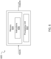
Fig. 6 is a block diagram of an example computing device. - The present disclosure is directed to methods and systems for operating an engine.
FIG. 1 illustrates anexample engine 100 of a type provided for use by an aircraft in subsonic flight. Theengine 100 ofFIG. 1 is a turbofan engine that generally comprises, in serial flow communication, afan 12 through which ambient air is propelled toward aninlet 32, acompressor section 14 for pressurizing the air, acombustor 16 in which the compressed air is mixed with fuel and ignited for generating an annular stream of hot combustion gases, and aturbine section 18 for extracting energy from the combustion gases, which are mixed by amixer 34 and exit via anexhaust nozzle 47. High-pressure rotor(s) of the turbine section 18 (referred to as "HPturbine 20") are mechanically linked to high-pressure rotor(s) of the compressor section 14 (referred to as "HPcompressor 22") through a high-pressure shaft 24. - According to the illustrated example, the
engine 100 is provided in the form of a multi-spool engine having a high pressure (HP) spool and a low pressure (LP) spool independently rotatable aboutaxis 11. However, it is understood that a multi-spool engine could have more than two spools. It should also be noted that the embodiments described herein also consider the use of single-spool engines. - Low-pressure rotor(s) of the turbine section 18 (referred to as "
LP turbine 26") are mechanically linked to the low-pressure rotor(s) of the compressor section 14 (referred to as "LP compressor 30") and/or thefan 12 through a concentric low-pressure shaft 28 (referred to as an "LP shaft 28") extending within the high-pressure shaft 24 and rotating independently therefrom. The high pressure components (HPturbine 20, HPcompressor 22, HP shaft 24) form the high pressure spool (referred to as "HP spool"), while the low pressure components (LP turbine 26,LP shaft 28, LP compressor 30) form the low pressure spool (referred to as "LP spool"). In the shown embodiment, thefan 12 extends forwardly from theLP shaft 28 and is mechanically coupled thereto to be driven by theLP turbine 26. The rotational speed of thefan 12, generally referred to as N1, is thus limited by the rotational speed of the LP spool, while the HP spool rotates at a second rotational speed generally referred to as N2. - The
compressor section 14,combustor 16 andturbine section 18 are contained within anengine core 40 surrounded by abypass duct 42 carrying bypass air generated by thefan 12. Anengine casing 44 surrounds theengine core 40, with thebypass duct 42 radially defined between theengine casing 44 andengine core 40. Illustratively, a plurality ofengine bypass struts 46 support theengine core 40 within theengine casing 44. - Control of the operation of the
engine 100 can be effected by one or more control systems, for example acontroller 110, which is communicatively coupled to theengine 100. The operation of theengine 100 can be controlled by way of one or more actuators, mechanical linkages, hydraulic systems, and the like. Thecontroller 110 can be coupled to the actuators, mechanical linkages, hydraulic systems, and the like, in any suitable fashion for effecting control of theengine 100. Thecontroller 110 can modulate the position and orientation of variable geometry mechanisms within theengine 100, the bleed level of theengine 100, and fuel flow, based on predetermined schedules or algorithms. In some embodiments, thecontroller 110 includes one or more FADEC(s), electronic engine controller(s) (EEC(s)), or the like, that are programmed to control the operation of theengine 100. -
Engine 100 may operate with a high bypass ratio, i.e. a ratio of the mass flow rate through thebypass duct 42 to the mass flow rate entering theengine core 40, for instance to increase propulsive efficiency and thus reduce fuel consumption. One of the drawbacks of increasing the engine bypass ratio is it suffers from a greater difference between the maximum thrust available at take-off and the maximum thrust available at maximum climb due to the reduced jet velocity. This may result in a choked flow at theexhaust nozzle 47, whereby the flow is travelling at the speed of sound (Mach 1). At such speeds, thefan 12 may have reached its aerodynamic or mechanical limit (rotating at a maximum rotational speed of the LP spool), for instance while the aircraft is climbing or flying at high altitudes, and may not be able to rotate any faster to increase thrust. It will be understood that the actual location of choked flow may vary in theexhaust nozzle 47 and is represented conceptually as occurring at a plane defining theexhaust nozzle 47. - As such, the present disclosure describes systems and methods for providing additional thrust to the
engine 100 in certain circumstances, by using one or more heat source to increase a temperature of bypass air flowing through theexhaust nozzle 47. The bypass air may be heated at various stages of theengine 100, such as in thebypass duct 42 and/or at or near theexhaust nozzle 47. As used herein, a heat source comprises one or more components capable of transferring heat to the bypass air, directly or indirectly. In some embodiments, the heat source comprises a power source of theengine 100 such as, but not limited, to a battery, a hydrogen fuel cell, an auxiliary power unit, and combinations thereof. Existing power sources for theengine 100, for instance in engines employing a hybrid powertrain, existing power sources for an aircraft, as well as dedicated power sources for the purposes of acting as a heat source, may be used. In some embodiments, the heat source is an electrical device that converts alternating current (AC) into heat. In some embodiments, the heat source is an electrical device that converts direct current (DC) into heat. In some embodiments, the heat source is operable to directly heat the bypass air. In some embodiments, the heat source is operable to apply heat to one or more conductive surfaces of theengine 100 by electromagnetic induction, and the bypass air is heated by convection heating as the bypass air comes in contact with the one or more conductive surface. Other means for heating the bypass air may be contemplated as well. - Referring to
FIGS. 2A-2C , there are shown three graphs depicting the effects of applying a heat source to heat bypass air flowing through thebypass duct 42 towards theexhaust nozzle 47, at a constant rotational speed (N1) of thefan 12, to increase exhaust gas temperature and thus provide additional thrust. Exhaust gas temperature as defined herein refers to the temperature of the gas leaving the engine at theexhaust nozzle 47.FIG. 2A illustrates N1 relative to ambient temperature.FIG. 2B illustrates net thrust relative to ambient temperature.FIG. 2C illustrates inter-turbine temperature (ITT - also called inter-stage turbine temperature) relative to ambient temperature. As used herein, ITT refers to the temperature of the gases in theengine core 40 between thehigh pressure turbine 20 and thelow pressure turbine 26, as illustrated inFIG. 1 . It will be understood that the use of ITT in this example is merely to indicate a temperature for which a thermal limit of the engine is reached. In some embodiments, ITT may be replaced with a surrogate or adjacent temperature, such as T4 (found at the exit of the combustor 16) or T41 (the first stator outlet temperature). In each ofFIGS. 2A-2C , the values for N1, net thrust and ITT, respectively, in an ideal scenario are represented by respectivedotted lines FIGS. 2A-2C , these values are each limited by the mechanical N1 limit, represented bylines bypass duct 42 towards theexhaust nozzle 47, thereby increasing the temperature of the mixed air at theexhaust nozzle 47, net thrust can be increased toline 203B. In addition, as shown inFIG. 2B , this increase in net thrust may be extended over a wider range of ambient temperatures, thus increasing the range of the thrust limit over a wider range of ambient temperatures for certain circumstances, such as when the aircraft is in max climb. As shown inFIG. 2A and 2C , N1 and ITT do not change after the heat source is applied to the bypass air. Thus, additional thrust is generated for a same N1 and ITT. - Referring to
FIGS. 3A-3C , various configurations are shown to heat bypass air flowing through thebypass duct 42 towards theexhaust nozzle 47. In these examples, aheat source 300 is shown to include acurrent source 302 and aheating element 304. It will be understood that this is for illustrative purposes only and other heat sources may be used instead or in combination therewith. - In some embodiments, and as shown in
FIG. 3A , existing engine surfaces are heated through conduction/induction heating. For instance, heating element(s) 304 may be applied to a radiallyouter surface 34a of themixer nozzle 34, a radiallyouter surface 40a of theengine core 40 and/or a radiallyinner surface 44a of theengine casing 44. WhileFIG. 3A depicts positioning theheating element 304 at the intersection betweensurfaces such surfaces separate heating elements 304. In some embodiments, two ormore heating elements 304 are operatively connected to a samecurrent source 302. Alternatively, or in combination therewith, eachheating element 304 may be operatively connected to its owncurrent source 302. in some embodiments, heat may be applied to anouter surface 46a of one or more bypass struts 46 . Any of the surfaces highlighted in bold inFig. 3A may be heated so as to transfer heat convectively to bypass air flowing thereby. Other existing surfaces within theengine 100 may be contemplated as well. In some embodiments, and as shown inFIG. 3B , the conductive surfaces heated by the one ormore heat source 300 may be one or morenew surface 308, i.e. additional geometries, introduced within theengine 100. For instance, anew surface 308 may comprise a plurality of fins positioned in thebypass duct 42, upstream from the exhaust nozzle. Thenew surface 308 may also be positioned elsewhere along thebypass duct 42, such aslocations new surface 308 may be attached to theinner surface 44a of theengine casing 44, the bypass struts 46, theouter surface 40a of theengine core 40, or any other location suitable for coming into contact with the bypass air without significantly affecting the performance of theengine 100. Other examples of anew surface 308 include arrays of fins, tubes, heated wires and the like. Suchadditional surfaces 308 should be designed to be substantially aerodynamic so as to minimize pressure loss, and noise created by their addition and avoid vortex-shedding to the extent possible. Theadditional surface 308 may be heated by a dedicated or existingpower source 300, for instance an induction heater or other heater type. All of the embodiments for thepower source 300 described with reference toFig. 3A are also applicable to thenew surface 308. - In other embodiments, and as shown in
FIG. 3C , a combination of existing and new conductive surfaces may be provided to heat the bypass air flowing through thebypass duct 42 towards themixer nozzle 34. In some cases, thesame heat source 300 may be used to heat more than one conductive surface, while in other cases a plurality ofheat sources 300 with respectivecurrent sources 302 andheating elements 304 may be provided. In some embodiments, a singlecurrent source 302 may be used to powermultiple heating elements 304 for multiple surfaces. Other combinations may be contemplated as well. As the number and size of conductive surfaces increases, the potential for providing a greater amount of heat to the bypass air increases as well due to the greater heat transfer surface area provided by such conductive surfaces. In addition, the energy required is inversely proportional to the surface area of such conductive surfaces, so an increase in surface area may result in more efficient heating of the bypass air. For example, in ideal heat transfer conditions for a typical medium by-pass turbofan in the 10,000-20,000 lbf thrust class range, 0.3 MW to 0.9 MW of electrical power may be used to provide an increase of 5 to 15 Rankine (or 3 to 8 Kelvin) of the EGT, thus providing between 1% and 3% additional thrust. Referring toFIG. 4 , there is shown anexemplary method 400 for operating anengine 100 to provide additional thrust in certain circumstances, the engine having anengine core 40, abypass duct 42, and anexhaust nozzle 47 as described above.Such method 400 may be performed by thecontroller 110 in part or in whole. - At
step 402, a request is received for an increase in thrust generated by theengine 100. In other words, theengine 100 is currently producing a given amount of thrust and the request is for more than the given amount of thrust. The request may come from a power lever of an aircraft, a thrust lever of the aircraft, a combined lever of the aircraft, or any other control mechanism operated by a pilot of the aircraft. In some embodiments, the request is generated by thecontroller 110 or another controller or computing device, such as an aircraft computer, in response to a detected state of theengine 100 or detected operating conditions of the aircraft. - At
step 404, in response to the receipt of the request atstep 402, it is determined if at least one operating condition for heat application-based thrust is met. As used herein heat application-based thrust refers to providing additional thrust by applying a heat source to heat bypass air flowing through the bypass duct towards theexhaust nozzle 47, as described herein. It will be understood that heat application-based thrust differs from other techniques for increasing thrust, such as increasing the speed of thefan 12 or the use of an afterburner. In some embodiments, heat application-based thrust may be used in combination with other techniques for increasing engine thrust. According to the invention, the operating condition for heat application-based thrust is a choked state of theexhaust nozzle 47. In some embodiments, the operating conditions for heat application-based thrust are a choked state of theexhaust nozzle 47 and thefan 12 operating at a mechanical limit. In some embodiments, a choked state of theexhaust nozzle 47 is approximated using on-board engine model(s) and based on available inputs from aircraft and/or engine sensors. In some embodiments, a choked state of theexhaust nozzle 47 is predetermined and step 404 comprises confirming the choked state of theexhaust nozzle 47 by reading a flag or field having been set as a result of the predetermined choked state of theexhaust nozzle 47. In some embodiments not being part of the claimed invention, the operating conditions for heat application-based thrust are independent of the choked state of the exhaust nozzle and instead relate to other engine and/or aircraft parameters, for example an available ITT margin as determined from an ITT measurement. Thecontroller 110 may consider one or more of an aircraft attitude, a Mach number, a rotational speed of thefan 12, an inlet total pressure, an ITT measurement, temperatures and/or pressures in the gas path, and a flight phase to determine whether at least one operating condition for heat application-based thrust is met. - At
step 406, when the one or more operating condition is met, aheat source 300 is applied to heat bypass air flowing through thebypass duct 42 flowing towards theexhaust nozzle 47. In some embodiments,step 406 comprises applying theheat source 300 to at least one conductive surface of theengine 100 and heating the bypass air through convection heat-transfer from the at least one conductive surface to the bypass air, as discussed above. Alternatively, the bypass air is heated directly by theheat source 300. The amount of energy/heat applied can be modulated from minimum to maximum capacity based on the desired thrust increase. - At
step 408, the increase in thrust is generated from an increase in temperature of the bypass air flowing through thebypass duct 42 and into theexhaust nozzle 47. - While
method 400 has been herein described for use when engine thrust is limited by, for instance, the mechanical and thermal limits of thefan 12, it is understood that the method may be used to provide additional thrust under other chokedexhaust nozzle 47 conditions, pending available energy from theapplicable heat source 300. - Referring to
FIG. 5 , there is illustrated anengine system 500, which is composed of theengine 100, a plurality ofsensors 510 and aheat source controller 520. It should be understood that certain elements of theengine 100, as shown inFIG. 5 , are omitted to facilitate understanding. It is also understood that while only oneheat source 300 is depicted inFIG. 5 , a plurality ofheat sources 300 may be provided, as discussed above. - The
sensors 510 are configured for detecting various parameters for theengine 100 and/or aircraft. While thesensors 510 are shown as being external to theengine 100, it should be understood that one or more of thesensors 510 may form part of theengine 100. In various embodiments, the number, type and positioning of thesensors 510 may vary. Thesensors 510 may be operable to determine that one or more operating condition for a choked state of theexhaust nozzle 47 are met, for instance by detecting one or more of an aircraft altitude, a Mach number, a rotational speed, temperatures or pressures of theengine 100, or a flight phase. As such, thesensors 510 may include altimeters, speed sensors, temperature sensors, pressure sensors, gyroscopes, as well as others types of sensors. Additionally, although illustrated here as physical sensors that are located at particular locations, it should be understood that in some cases, one or more of thesensors 510 can be virtual sensors, that is to say, instruments which make use of measurements from other sensors (physical or virtual) to derive a desired parameter (for example using on-board engine models). - The
heat source controller 520 may form part of thecontroller 110 and be operable to control the one ormore heat sources 300 based on, inter alia, information acquired from thesensors 510, which can include applying heat to one or more surfaces in thebypass duct 42. More particularly, applying heat may include diverting power from one or more power sources to one or more heaters, for instance induction heaters, which are positioned proximal to said conductive surfaces to be heated. As discussed above, applying heat to the bypass air in thebypass duct 42 may increase the exhaust gas temperature and thus the gas velocity at theexhaust nozzle 47, allowing for more engine thrust to be produced. Theheat source controller 520 may thus be configured for operating the one ormore heats sources 300 to selectively increase the thrust of theengine 100. In some embodiments, the engine thrust may be increased by approximately one to three percent, although other percent increases may be contemplated as well. - With reference to
Fig. 6 , an example of acomputing device 600 is illustrated. For simplicity only onecomputing device 600 is shown but the system may includemore computing devices 600 operable to exchange data. Thecomputing devices 600 may be the same or different types of devices. Theheat source controller 520 may be implemented with one ormore computing devices 600. Note that theheat source controller 520 can be implemented as part of a full-authority digital engine controls (FADEC) or other similar device, including electronic engine control (EEC), engine control unit (ECU), and the like. - The
computing device 600 comprises aprocessing unit 602 and amemory 604 which has stored therein computer-executable instructions 606. Theprocessing unit 602 may comprise any suitable devices configured to implement themethod 400 such thatinstructions 606, when executed by thecomputing device 600 or other programmable apparatus, may cause the functions/acts/steps performed as part of themethod 400 as described herein to be executed. Theprocessing unit 602 may comprise, for example, any type of general-purpose microprocessor or microcontroller, a digital signal processing (DSP) processor, a central processing unit (CPU), an integrated circuit, a field programmable gate array (FPGA), a reconfigurable processor, other suitably programmed or programmable logic circuits, or any combination thereof. - The
memory 604 may comprise any suitable known or other machine-readable storage medium. Thememory 604 may comprise non-transitory computer readable storage medium, for example, but not limited to, an electronic, magnetic, optical, electromagnetic, infrared, or semiconductor system, apparatus, or device, or any suitable combination of the foregoing. Thememory 604 may include a suitable combination of any type of computer memory that is located either internally or externally to device, for example random-access memory (RAM), read-only memory (ROM), compact disc read-only memory (CDROM), electro-optical memory, magnetooptical memory, erasable programmable read-only memory (EPROM), and electrically-erasable programmable read-only memory (EEPROM), Ferroelectric RAM (FRAM) or the like.Memory 604 may comprise any storage means (e.g., devices) suitable for retrievably storing machine-readable instructions 606 executable by processingunit 602. - The methods and systems for operating an engine described herein may be implemented in a high level procedural or object oriented programming or scripting language, or a combination thereof, to communicate with or assist in the operation of a computer system, for example the
computing device 600. Alternatively, the methods and systems for operating an engine may be implemented in assembly or machine language. The language may be a compiled or interpreted language. Program code for implementing the methods and systems for operating an engine may be stored on a storage media or a device, for example a ROM, a magnetic disk, an optical disc, a flash drive, or any other suitable storage media or device. The program code may be readable by a general or special-purpose programmable computer for configuring and operating the computer when the storage media or device is read by the computer to perform the procedures described herein. Embodiments of the methods and systems for operating an engine may also be considered to be implemented by way of a non-transitory computer-readable storage medium having a computer program stored thereon. The computer program may comprise computer-readable instructions which cause a computer, or more specifically theprocessing unit 602 of thecomputing device 600, to operate in a specific and predefined manner to perform the functions described herein, for example those described in themethod 400. - Computer-executable instructions may be in many forms, including program modules, executed by one or more computers or other devices. Generally, program modules include routines, programs, objects, components, data structures, etc., that perform particular tasks or implement particular abstract data types. Typically the functionality of the program modules may be combined or distributed as desired in various embodiments.
- The embodiments described herein are implemented by physical computer hardware, including computing devices, servers, receivers, transmitters, processors, memory, displays, and networks. The embodiments described herein provide useful physical machines and particularly configured computer hardware arrangements. The embodiments described herein are directed to electronic machines and methods implemented by electronic machines adapted for processing and transforming electromagnetic signals which represent various types of information. The embodiments described herein pervasively and integrally relate to machines, and their uses; and the embodiments described herein have no meaning or practical applicability outside their use with computer hardware, machines, and various hardware components. Substituting the physical hardware particularly configured to implement various acts for non-physical hardware, using mental steps for example, may substantially affect the way the embodiments work. Such computer hardware limitations are clearly essential elements of the embodiments described herein, and they cannot be omitted or substituted for mental means without having a material effect on the operation and structure of the embodiments described herein. The computer hardware is essential to implement the various embodiments described herein and is not merely used to perform steps expeditiously and in an efficient manner.
- The term "connected" or "coupled to" may include both direct coupling (in which two elements that are coupled to each other contact each other) and indirect coupling (in which at least one additional element is located between the two elements).
- The technical solution of embodiments may be in the form of a software product. The software product may be stored in a non-volatile or non-transitory storage medium, which can be a compact disk read-only memory (CD-ROM), a USB flash disk, or a removable hard disk. The software product includes a number of instructions that enable a computer device (personal computer, server, or network device) to execute the methods provided by the embodiments.
- The embodiments described in this document provide non-limiting examples of possible implementations of the present technology. Upon review of the present disclosure, a person of ordinary skill in the art will recognize that changes may be made to the embodiments described herein without departing from the scope of the appended claims.
Claims (15)
- A method for operating an engine (100), the engine having an engine core (40), a bypass duct (42), and an exhaust nozzle (47), the method comprising:receiving (402) a request for an increase in thrust generated by the engine (100);in response to receipt of the request, determining (404) that at least one operating condition for heat application-based thrust is met;in response to the determining, applying (406) a heat source (300) to heat bypass air flowing through the bypass duct (42) towards the exhaust nozzle (47); andgenerating the increase in thrust from an increased temperature of mixed bypass and core air at the exhaust nozzle (47); characterised in that the at least one operating condition for heat application-based thrust comprises a choked state of the exhaust nozzle (47).
- A system for operating an engine, the engine (100) having an engine core (40), a bypass duct (42), and an exhaust nozzle (47), the system comprising: a heat source (300) to heat bypass air flowing trough the bypass duct (42) towards the exhaust nozzle (47);a processor (602); anda non-transitory computer-readable medium (604) having stored thereon program instructions (606) executable by the processor for:receiving a request for an increase in thrust generated by the engine (100);in response to receipt of the request, determining that at least one operating condition for heat application-based thrust is met;in response to the determining, controlling the heat source (300) to generate the increase in thrust from an increased temperature of mixed bypass and core air at the exhaust nozzle (47); characterised in that the at least one operating condition for heat application-based thrust comprises a choked state of the exhaust nozzle (47).
- The method of claim 1, or the system of claim 2, wherein:the heat source (300) is an electrical device that converts alternating current (AC) or direct current (DC) into heat; andapplying the heat source (300) to heat bypass air includes applying the heat source to a radially outer surface of a mixer.
- The method of claim 1 or 3, or the system of claim 2 or 3, wherein the at least one operating condition for heat application-based thrust comprises at least one of an aircraft altitude, a Mach number, a rotational speed of the engine (100), and a flight phase.
- The method of claim 1, 3 or 4, or the system of any of claims 2-4, wherein applying the heat source (300) comprises applying the heat source to at least one conductive surface (34a, 40a, 44a, 308) in the engine and heating the bypass air through convection heat-transfer from the at least one conductive surface to the bypass air.
- The method of claim 5, or the system of claim 5, wherein the heat source (300) is an induction heater and applying the heat source to the at least one conductive surface (34a, 40a, 44a, 308) comprises inductively heating the at least one conductive surface (34a, 40a, 44a, 308).
- The method of claim 5 or 6, or the system of claim 5 or 6, wherein applying the heat source (300) to the at least one conductive surface (34a, 40a, 44a) of the engine comprises applying the heat source to at least one existing engine surface (34a, 40a, 44a).
- The method of claim 7, or the system of claim 7, wherein applying the heat source to at least one existing engine surface (34a, 40a, 44a) comprises applying the heat source to at least one of a radially outer surface of a mixer nozzle (34a), a radially outer surface of the engine core (40a), a radially inner surface of an engine casing (44a) surrounding the engine core (40) and an engine bypass strut (46).
- The method of any of claims 5-8, or the system of any of claims 5-8, wherein applying the heat source (300) to the at least one conductive surface of the engine comprises applying the heat source to at least one additional engine surface (308) dedicated to heating the bypass air.
- The method of any of claims 1 or 3-9, or the system of any of claims 2-9, wherein applying the heat source comprises powering the heat source (300) with at least one of a battery, a hydrogen fuel cell, and an auxiliary power unit.
- The method of claim 10, or the system of claim 10, wherein powering the heat source comprises drawing power from an existing power source in the engine (100).
- An engine system comprising:the system defined in claim 2;an engine (100) having an engine core (40), a bypass duct (42), and an engine nozzle (47);wherein:the heat source (300) is positioned relatively to at least one conductive surface (34a, 40a, 44a, 308) of the engine; andheat from the heat source (300) is applied to the at least one conductive surface (34a, 40a, 44a, 308) of the engine when the at least one operating condition is met to generate an increase in thrust from an increased temperature of mixed bypass and core air at the exhaust nozzle (47) through convection heating of the bypass air from the at least one conductive surface.
- The engine system of claim 12, wherein the heat source (300) is an induction heater configured to inductively heat the at least one conductive surface (34a, 40a, 44a, 308).
- The engine system of claim 12 or 13, wherein the at least one conductive surface (34a, 40a, 44a, 308) comprises a radially outer surface of a mixer nozzle (34a), a radially outer surface of the engine core (40a), a radially inner surface of an engine casing (44a) surrounding the engine core (40) and an engine bypass strut (46).
- The engine system of claim 12, 13 or 14, wherein the at least one conductive surface (34a, 40a, 44a, 308) comprises at least one engine surface (308) dedicated to heating the bypass air.
Applications Claiming Priority (1)
| Application Number | Priority Date | Filing Date | Title |
|---|---|---|---|
| US17/402,352 US11713733B2 (en) | 2021-08-13 | 2021-08-13 | Methods and systems for operating an engine to generate additional thrust |
Publications (2)
| Publication Number | Publication Date |
|---|---|
| EP4134538A1 EP4134538A1 (en) | 2023-02-15 |
| EP4134538B1 true EP4134538B1 (en) | 2025-05-28 |
Family
ID=82899028
Family Applications (1)
| Application Number | Title | Priority Date | Filing Date |
|---|---|---|---|
| EP22189972.7A Active EP4134538B1 (en) | 2021-08-13 | 2022-08-11 | Methods and systems for operating an engine to generate additional thrust |
Country Status (3)
| Country | Link |
|---|---|
| US (1) | US11713733B2 (en) |
| EP (1) | EP4134538B1 (en) |
| CA (1) | CA3169844A1 (en) |
Family Cites Families (9)
| Publication number | Priority date | Publication date | Assignee | Title |
|---|---|---|---|---|
| US6837225B1 (en) * | 2003-07-29 | 2005-01-04 | Toyota Jidosha Kabushiki Kaisha | Fuel supply control device for a turbo-charged diesel aircraft engine |
| US7690186B2 (en) | 2005-11-09 | 2010-04-06 | Pratt & Whitney Canada Corp. | Gas turbine engine including apparatus to transfer power between multiple shafts |
| US7770381B2 (en) * | 2006-12-18 | 2010-08-10 | General Electric Company | Duct burning mixed flow turbofan and method of operation |
| US8397487B2 (en) * | 2011-02-28 | 2013-03-19 | General Electric Company | Environmental control system supply precooler bypass |
| US10308365B2 (en) | 2015-10-12 | 2019-06-04 | Codrin-Gruie (CG) Cantemir | Fully integrated hybrid electric jet engine |
| US11131208B2 (en) | 2016-09-01 | 2021-09-28 | Rolls-Royce North American Technologies, Inc. | Embedded electric generator in turbine engine |
| US10941706B2 (en) | 2018-02-13 | 2021-03-09 | General Electric Company | Closed cycle heat engine for a gas turbine engine |
| US11143104B2 (en) | 2018-02-20 | 2021-10-12 | General Electric Company | Thermal management system |
| FR3088961A1 (en) * | 2018-11-22 | 2020-05-29 | Airbus Operations (S.A.S.) | Turbomachine equipped with an air intake defrosting system. |
-
2021
- 2021-08-13 US US17/402,352 patent/US11713733B2/en active Active
-
2022
- 2022-08-04 CA CA3169844A patent/CA3169844A1/en active Pending
- 2022-08-11 EP EP22189972.7A patent/EP4134538B1/en active Active
Also Published As
| Publication number | Publication date |
|---|---|
| CA3169844A1 (en) | 2023-02-13 |
| US20230050939A1 (en) | 2023-02-16 |
| US11713733B2 (en) | 2023-08-01 |
| EP4134538A1 (en) | 2023-02-15 |
Similar Documents
| Publication | Publication Date | Title |
|---|---|---|
| US10752375B2 (en) | Aircraft system | |
| EP3712074B1 (en) | Method and system for setting power of an aircraft engine | |
| EP3444464B1 (en) | System and method for rotating a gas turbine engine during a motoring cycle | |
| EP3315743B1 (en) | Power plant thrust management system for turboprop engines | |
| CA2975356C (en) | System and method for an engine controller based on acceleration power | |
| EP3450729B1 (en) | Variable geometries transient control logic | |
| EP4119775A1 (en) | Active clearance control system and method for an aircraft engine | |
| EP4134538B1 (en) | Methods and systems for operating an engine to generate additional thrust | |
| EP4141241A1 (en) | Method and system for operating an engine to generate additional thrust | |
| CA2901735C (en) | Gas turbine engine configuration interface | |
| EP2805025B1 (en) | Gas turbine engine tip clearance control | |
| EP4148256B1 (en) | Output power management for engines | |
| EP3633167A1 (en) | Corrected fuel-flow-rate-based control for variable geometry mechanisms | |
| CA3073692C (en) | Systems and methods for control of engine variable geometry mechanism | |
| US20250341190A1 (en) | Partial-admission turbine assembly for an aircraft and method for controlling same | |
| Kong et al. | Steady-state/transient performance simulation of the propulsion system for the canard rotor wing uav during flight mode transition | |
| Bose | Off-Design Running of Aircraft Gas Turbines |
Legal Events
| Date | Code | Title | Description |
|---|---|---|---|
| PUAI | Public reference made under article 153(3) epc to a published international application that has entered the european phase |
Free format text: ORIGINAL CODE: 0009012 |
|
| STAA | Information on the status of an ep patent application or granted ep patent |
Free format text: STATUS: THE APPLICATION HAS BEEN PUBLISHED |
|
| AK | Designated contracting states |
Kind code of ref document: A1 Designated state(s): AL AT BE BG CH CY CZ DE DK EE ES FI FR GB GR HR HU IE IS IT LI LT LU LV MC MK MT NL NO PL PT RO RS SE SI SK SM TR |
|
| STAA | Information on the status of an ep patent application or granted ep patent |
Free format text: STATUS: REQUEST FOR EXAMINATION WAS MADE |
|
| 17P | Request for examination filed |
Effective date: 20230814 |
|
| RBV | Designated contracting states (corrected) |
Designated state(s): AL AT BE BG CH CY CZ DE DK EE ES FI FR GB GR HR HU IE IS IT LI LT LU LV MC MK MT NL NO PL PT RO RS SE SI SK SM TR |
|
| GRAP | Despatch of communication of intention to grant a patent |
Free format text: ORIGINAL CODE: EPIDOSNIGR1 |
|
| STAA | Information on the status of an ep patent application or granted ep patent |
Free format text: STATUS: GRANT OF PATENT IS INTENDED |
|
| INTG | Intention to grant announced |
Effective date: 20250116 |
|
| GRAS | Grant fee paid |
Free format text: ORIGINAL CODE: EPIDOSNIGR3 |
|
| GRAA | (expected) grant |
Free format text: ORIGINAL CODE: 0009210 |
|
| STAA | Information on the status of an ep patent application or granted ep patent |
Free format text: STATUS: THE PATENT HAS BEEN GRANTED |
|
| AK | Designated contracting states |
Kind code of ref document: B1 Designated state(s): AL AT BE BG CH CY CZ DE DK EE ES FI FR GB GR HR HU IE IS IT LI LT LU LV MC MK MT NL NO PL PT RO RS SE SI SK SM TR |
|
| REG | Reference to a national code |
Ref country code: GB Ref legal event code: FG4D |
|
| REG | Reference to a national code |
Ref country code: CH Ref legal event code: EP |
|
| REG | Reference to a national code |
Ref country code: DE Ref legal event code: R096 Ref document number: 602022015154 Country of ref document: DE |
|
| REG | Reference to a national code |
Ref country code: IE Ref legal event code: FG4D |
|
| REG | Reference to a national code |
Ref country code: NL Ref legal event code: MP Effective date: 20250528 |
|
| PG25 | Lapsed in a contracting state [announced via postgrant information from national office to epo] |
Ref country code: ES Free format text: LAPSE BECAUSE OF FAILURE TO SUBMIT A TRANSLATION OF THE DESCRIPTION OR TO PAY THE FEE WITHIN THE PRESCRIBED TIME-LIMIT Effective date: 20250528 Ref country code: FI Free format text: LAPSE BECAUSE OF FAILURE TO SUBMIT A TRANSLATION OF THE DESCRIPTION OR TO PAY THE FEE WITHIN THE PRESCRIBED TIME-LIMIT Effective date: 20250528 |
|
| PGFP | Annual fee paid to national office [announced via postgrant information from national office to epo] |
Ref country code: DE Payment date: 20250724 Year of fee payment: 4 |
|
| REG | Reference to a national code |
Ref country code: LT Ref legal event code: MG9D |
|
| PG25 | Lapsed in a contracting state [announced via postgrant information from national office to epo] |
Ref country code: NO Free format text: LAPSE BECAUSE OF FAILURE TO SUBMIT A TRANSLATION OF THE DESCRIPTION OR TO PAY THE FEE WITHIN THE PRESCRIBED TIME-LIMIT Effective date: 20250828 Ref country code: GR Free format text: LAPSE BECAUSE OF FAILURE TO SUBMIT A TRANSLATION OF THE DESCRIPTION OR TO PAY THE FEE WITHIN THE PRESCRIBED TIME-LIMIT Effective date: 20250829 |
|
| PG25 | Lapsed in a contracting state [announced via postgrant information from national office to epo] |
Ref country code: NL Free format text: LAPSE BECAUSE OF FAILURE TO SUBMIT A TRANSLATION OF THE DESCRIPTION OR TO PAY THE FEE WITHIN THE PRESCRIBED TIME-LIMIT Effective date: 20250528 Ref country code: PL Free format text: LAPSE BECAUSE OF FAILURE TO SUBMIT A TRANSLATION OF THE DESCRIPTION OR TO PAY THE FEE WITHIN THE PRESCRIBED TIME-LIMIT Effective date: 20250528 |
|
| PG25 | Lapsed in a contracting state [announced via postgrant information from national office to epo] |
Ref country code: BG Free format text: LAPSE BECAUSE OF FAILURE TO SUBMIT A TRANSLATION OF THE DESCRIPTION OR TO PAY THE FEE WITHIN THE PRESCRIBED TIME-LIMIT Effective date: 20250528 |
|
| PG25 | Lapsed in a contracting state [announced via postgrant information from national office to epo] |
Ref country code: HR Free format text: LAPSE BECAUSE OF FAILURE TO SUBMIT A TRANSLATION OF THE DESCRIPTION OR TO PAY THE FEE WITHIN THE PRESCRIBED TIME-LIMIT Effective date: 20250528 |
|
| PGFP | Annual fee paid to national office [announced via postgrant information from national office to epo] |
Ref country code: FR Payment date: 20250723 Year of fee payment: 4 Ref country code: AT Payment date: 20251020 Year of fee payment: 4 |
|
| PG25 | Lapsed in a contracting state [announced via postgrant information from national office to epo] |
Ref country code: RS Free format text: LAPSE BECAUSE OF FAILURE TO SUBMIT A TRANSLATION OF THE DESCRIPTION OR TO PAY THE FEE WITHIN THE PRESCRIBED TIME-LIMIT Effective date: 20250828 |
|
| PG25 | Lapsed in a contracting state [announced via postgrant information from national office to epo] |
Ref country code: IS Free format text: LAPSE BECAUSE OF FAILURE TO SUBMIT A TRANSLATION OF THE DESCRIPTION OR TO PAY THE FEE WITHIN THE PRESCRIBED TIME-LIMIT Effective date: 20250928 |
|
| PG25 | Lapsed in a contracting state [announced via postgrant information from national office to epo] |
Ref country code: LV Free format text: LAPSE BECAUSE OF FAILURE TO SUBMIT A TRANSLATION OF THE DESCRIPTION OR TO PAY THE FEE WITHIN THE PRESCRIBED TIME-LIMIT Effective date: 20250528 |
|
| REG | Reference to a national code |
Ref country code: AT Ref legal event code: MK05 Ref document number: 1798716 Country of ref document: AT Kind code of ref document: T Effective date: 20250528 |
|
| PG25 | Lapsed in a contracting state [announced via postgrant information from national office to epo] |
Ref country code: SM Free format text: LAPSE BECAUSE OF FAILURE TO SUBMIT A TRANSLATION OF THE DESCRIPTION OR TO PAY THE FEE WITHIN THE PRESCRIBED TIME-LIMIT Effective date: 20250528 Ref country code: AT Free format text: LAPSE BECAUSE OF FAILURE TO SUBMIT A TRANSLATION OF THE DESCRIPTION OR TO PAY THE FEE WITHIN THE PRESCRIBED TIME-LIMIT Effective date: 20250528 Ref country code: DK Free format text: LAPSE BECAUSE OF FAILURE TO SUBMIT A TRANSLATION OF THE DESCRIPTION OR TO PAY THE FEE WITHIN THE PRESCRIBED TIME-LIMIT Effective date: 20250528 |
|
| PG25 | Lapsed in a contracting state [announced via postgrant information from national office to epo] |
Ref country code: CZ Free format text: LAPSE BECAUSE OF FAILURE TO SUBMIT A TRANSLATION OF THE DESCRIPTION OR TO PAY THE FEE WITHIN THE PRESCRIBED TIME-LIMIT Effective date: 20250528 |
|
| PG25 | Lapsed in a contracting state [announced via postgrant information from national office to epo] |
Ref country code: EE Free format text: LAPSE BECAUSE OF FAILURE TO SUBMIT A TRANSLATION OF THE DESCRIPTION OR TO PAY THE FEE WITHIN THE PRESCRIBED TIME-LIMIT Effective date: 20250528 |
|
| PG25 | Lapsed in a contracting state [announced via postgrant information from national office to epo] |
Ref country code: SK Free format text: LAPSE BECAUSE OF FAILURE TO SUBMIT A TRANSLATION OF THE DESCRIPTION OR TO PAY THE FEE WITHIN THE PRESCRIBED TIME-LIMIT Effective date: 20250528 |
|
| PG25 | Lapsed in a contracting state [announced via postgrant information from national office to epo] |
Ref country code: IT Free format text: LAPSE BECAUSE OF FAILURE TO SUBMIT A TRANSLATION OF THE DESCRIPTION OR TO PAY THE FEE WITHIN THE PRESCRIBED TIME-LIMIT Effective date: 20250528 |
|
| REG | Reference to a national code |
Ref country code: DE Ref legal event code: R097 Ref document number: 602022015154 Country of ref document: DE |
|
| PG25 | Lapsed in a contracting state [announced via postgrant information from national office to epo] |
Ref country code: RO Free format text: LAPSE BECAUSE OF FAILURE TO SUBMIT A TRANSLATION OF THE DESCRIPTION OR TO PAY THE FEE WITHIN THE PRESCRIBED TIME-LIMIT Effective date: 20250528 |
|
| REG | Reference to a national code |
Ref country code: CH Ref legal event code: H13 Free format text: ST27 STATUS EVENT CODE: U-0-0-H10-H13 (AS PROVIDED BY THE NATIONAL OFFICE) Effective date: 20260324 |
|
| PG25 | Lapsed in a contracting state [announced via postgrant information from national office to epo] |
Ref country code: MC Free format text: LAPSE BECAUSE OF FAILURE TO SUBMIT A TRANSLATION OF THE DESCRIPTION OR TO PAY THE FEE WITHIN THE PRESCRIBED TIME-LIMIT Effective date: 20250528 |
|
| PLBE | No opposition filed within time limit |
Free format text: ORIGINAL CODE: 0009261 |
|
| STAA | Information on the status of an ep patent application or granted ep patent |
Free format text: STATUS: NO OPPOSITION FILED WITHIN TIME LIMIT |
|
| REG | Reference to a national code |
Ref country code: CH Ref legal event code: L10 Free format text: ST27 STATUS EVENT CODE: U-0-0-L10-L00 (AS PROVIDED BY THE NATIONAL OFFICE) Effective date: 20260409 |
|
| PG25 | Lapsed in a contracting state [announced via postgrant information from national office to epo] |
Ref country code: LU Free format text: LAPSE BECAUSE OF NON-PAYMENT OF DUE FEES Effective date: 20250811 |
|
| PG25 | Lapsed in a contracting state [announced via postgrant information from national office to epo] |
Ref country code: CH Free format text: LAPSE BECAUSE OF NON-PAYMENT OF DUE FEES Effective date: 20250831 |