EP4134536A1 - Vehicle control method and vehicle control device - Google Patents
Vehicle control method and vehicle control device Download PDFInfo
- Publication number
- EP4134536A1 EP4134536A1 EP20930356.9A EP20930356A EP4134536A1 EP 4134536 A1 EP4134536 A1 EP 4134536A1 EP 20930356 A EP20930356 A EP 20930356A EP 4134536 A1 EP4134536 A1 EP 4134536A1
- Authority
- EP
- European Patent Office
- Prior art keywords
- temperature
- lower limit
- predetermined
- engine
- accelerator
- Prior art date
- Legal status (The legal status is an assumption and is not a legal conclusion. Google has not performed a legal analysis and makes no representation as to the accuracy of the status listed.)
- Withdrawn
Links
Images




Classifications
-
- F—MECHANICAL ENGINEERING; LIGHTING; HEATING; WEAPONS; BLASTING
- F01—MACHINES OR ENGINES IN GENERAL; ENGINE PLANTS IN GENERAL; STEAM ENGINES
- F01N—GAS-FLOW SILENCERS OR EXHAUST APPARATUS FOR MACHINES OR ENGINES IN GENERAL; GAS-FLOW SILENCERS OR EXHAUST APPARATUS FOR INTERNAL-COMBUSTION ENGINES
- F01N3/00—Exhaust or silencing apparatus having means for purifying, rendering innocuous, or otherwise treating exhaust
- F01N3/02—Exhaust or silencing apparatus having means for purifying, rendering innocuous, or otherwise treating exhaust for cooling, or for removing solid constituents of, exhaust
- F01N3/021—Exhaust or silencing apparatus having means for purifying, rendering innocuous, or otherwise treating exhaust for cooling, or for removing solid constituents of, exhaust by means of filters
- F01N3/023—Exhaust or silencing apparatus having means for purifying, rendering innocuous, or otherwise treating exhaust for cooling, or for removing solid constituents of, exhaust by means of filters using means for regenerating the filters, e.g. by burning trapped particles
-
- B—PERFORMING OPERATIONS; TRANSPORTING
- B60—VEHICLES IN GENERAL
- B60W—CONJOINT CONTROL OF VEHICLE SUB-UNITS OF DIFFERENT TYPE OR DIFFERENT FUNCTION; CONTROL SYSTEMS SPECIALLY ADAPTED FOR HYBRID VEHICLES; ROAD VEHICLE DRIVE CONTROL SYSTEMS FOR PURPOSES NOT RELATED TO THE CONTROL OF A PARTICULAR SUB-UNIT
- B60W50/00—Details of control systems for road vehicle drive control not related to the control of a particular sub-unit, e.g. process diagnostic or vehicle driver interfaces
- B60W50/08—Interaction between the driver and the control system
- B60W50/12—Limiting control by the driver depending on vehicle state, e.g. interlocking means for the control input for preventing unsafe operation
-
- F—MECHANICAL ENGINEERING; LIGHTING; HEATING; WEAPONS; BLASTING
- F01—MACHINES OR ENGINES IN GENERAL; ENGINE PLANTS IN GENERAL; STEAM ENGINES
- F01N—GAS-FLOW SILENCERS OR EXHAUST APPARATUS FOR MACHINES OR ENGINES IN GENERAL; GAS-FLOW SILENCERS OR EXHAUST APPARATUS FOR INTERNAL-COMBUSTION ENGINES
- F01N3/00—Exhaust or silencing apparatus having means for purifying, rendering innocuous, or otherwise treating exhaust
- F01N3/02—Exhaust or silencing apparatus having means for purifying, rendering innocuous, or otherwise treating exhaust for cooling, or for removing solid constituents of, exhaust
- F01N3/021—Exhaust or silencing apparatus having means for purifying, rendering innocuous, or otherwise treating exhaust for cooling, or for removing solid constituents of, exhaust by means of filters
-
- F—MECHANICAL ENGINEERING; LIGHTING; HEATING; WEAPONS; BLASTING
- F01—MACHINES OR ENGINES IN GENERAL; ENGINE PLANTS IN GENERAL; STEAM ENGINES
- F01N—GAS-FLOW SILENCERS OR EXHAUST APPARATUS FOR MACHINES OR ENGINES IN GENERAL; GAS-FLOW SILENCERS OR EXHAUST APPARATUS FOR INTERNAL-COMBUSTION ENGINES
- F01N3/00—Exhaust or silencing apparatus having means for purifying, rendering innocuous, or otherwise treating exhaust
- F01N3/08—Exhaust or silencing apparatus having means for purifying, rendering innocuous, or otherwise treating exhaust for rendering innocuous
- F01N3/10—Exhaust or silencing apparatus having means for purifying, rendering innocuous, or otherwise treating exhaust for rendering innocuous by thermal or catalytic conversion of noxious components of exhaust
- F01N3/101—Three-way catalysts
-
- F—MECHANICAL ENGINEERING; LIGHTING; HEATING; WEAPONS; BLASTING
- F01—MACHINES OR ENGINES IN GENERAL; ENGINE PLANTS IN GENERAL; STEAM ENGINES
- F01N—GAS-FLOW SILENCERS OR EXHAUST APPARATUS FOR MACHINES OR ENGINES IN GENERAL; GAS-FLOW SILENCERS OR EXHAUST APPARATUS FOR INTERNAL-COMBUSTION ENGINES
- F01N9/00—Electrical control of exhaust gas treating apparatus
- F01N9/002—Electrical control of exhaust gas treating apparatus of filter regeneration
-
- F—MECHANICAL ENGINEERING; LIGHTING; HEATING; WEAPONS; BLASTING
- F02—COMBUSTION ENGINES; HOT-GAS OR COMBUSTION-PRODUCT ENGINE PLANTS
- F02D—CONTROLLING COMBUSTION ENGINES
- F02D41/00—Electrical control of supply of combustible mixture or its constituents
- F02D41/0002—Controlling intake air
- F02D41/0005—Controlling intake air during deceleration
-
- F—MECHANICAL ENGINEERING; LIGHTING; HEATING; WEAPONS; BLASTING
- F02—COMBUSTION ENGINES; HOT-GAS OR COMBUSTION-PRODUCT ENGINE PLANTS
- F02D—CONTROLLING COMBUSTION ENGINES
- F02D41/00—Electrical control of supply of combustible mixture or its constituents
- F02D41/02—Circuit arrangements for generating control signals
- F02D41/021—Introducing corrections for particular conditions exterior to the engine
- F02D41/0235—Introducing corrections for particular conditions exterior to the engine in relation with the state of the exhaust gas treating apparatus
- F02D41/027—Introducing corrections for particular conditions exterior to the engine in relation with the state of the exhaust gas treating apparatus to purge or regenerate the exhaust gas treating apparatus
- F02D41/029—Introducing corrections for particular conditions exterior to the engine in relation with the state of the exhaust gas treating apparatus to purge or regenerate the exhaust gas treating apparatus the exhaust gas treating apparatus being a particulate filter
-
- F—MECHANICAL ENGINEERING; LIGHTING; HEATING; WEAPONS; BLASTING
- F02—COMBUSTION ENGINES; HOT-GAS OR COMBUSTION-PRODUCT ENGINE PLANTS
- F02D—CONTROLLING COMBUSTION ENGINES
- F02D41/00—Electrical control of supply of combustible mixture or its constituents
- F02D41/02—Circuit arrangements for generating control signals
- F02D41/04—Introducing corrections for particular operating conditions
- F02D41/12—Introducing corrections for particular operating conditions for deceleration
- F02D41/123—Introducing corrections for particular operating conditions for deceleration the fuel injection being cut-off
-
- F—MECHANICAL ENGINEERING; LIGHTING; HEATING; WEAPONS; BLASTING
- F02—COMBUSTION ENGINES; HOT-GAS OR COMBUSTION-PRODUCT ENGINE PLANTS
- F02D—CONTROLLING COMBUSTION ENGINES
- F02D43/00—Conjoint electrical control of two or more functions, e.g. ignition, fuel-air mixture, recirculation, supercharging or exhaust-gas treatment
-
- B—PERFORMING OPERATIONS; TRANSPORTING
- B60—VEHICLES IN GENERAL
- B60W—CONJOINT CONTROL OF VEHICLE SUB-UNITS OF DIFFERENT TYPE OR DIFFERENT FUNCTION; CONTROL SYSTEMS SPECIALLY ADAPTED FOR HYBRID VEHICLES; ROAD VEHICLE DRIVE CONTROL SYSTEMS FOR PURPOSES NOT RELATED TO THE CONTROL OF A PARTICULAR SUB-UNIT
- B60W2510/00—Input parameters relating to a particular sub-units
- B60W2510/06—Combustion engines, Gas turbines
- B60W2510/0638—Engine speed
-
- B—PERFORMING OPERATIONS; TRANSPORTING
- B60—VEHICLES IN GENERAL
- B60W—CONJOINT CONTROL OF VEHICLE SUB-UNITS OF DIFFERENT TYPE OR DIFFERENT FUNCTION; CONTROL SYSTEMS SPECIALLY ADAPTED FOR HYBRID VEHICLES; ROAD VEHICLE DRIVE CONTROL SYSTEMS FOR PURPOSES NOT RELATED TO THE CONTROL OF A PARTICULAR SUB-UNIT
- B60W2510/00—Input parameters relating to a particular sub-units
- B60W2510/06—Combustion engines, Gas turbines
- B60W2510/068—Engine exhaust temperature
-
- F—MECHANICAL ENGINEERING; LIGHTING; HEATING; WEAPONS; BLASTING
- F01—MACHINES OR ENGINES IN GENERAL; ENGINE PLANTS IN GENERAL; STEAM ENGINES
- F01N—GAS-FLOW SILENCERS OR EXHAUST APPARATUS FOR MACHINES OR ENGINES IN GENERAL; GAS-FLOW SILENCERS OR EXHAUST APPARATUS FOR INTERNAL-COMBUSTION ENGINES
- F01N2430/00—Influencing exhaust purification, e.g. starting of catalytic reaction, filter regeneration, or the like, by controlling engine operating characteristics
- F01N2430/08—Influencing exhaust purification, e.g. starting of catalytic reaction, filter regeneration, or the like, by controlling engine operating characteristics by modifying ignition or injection timing
- F01N2430/085—Influencing exhaust purification, e.g. starting of catalytic reaction, filter regeneration, or the like, by controlling engine operating characteristics by modifying ignition or injection timing at least a part of the injection taking place during expansion or exhaust stroke
-
- F—MECHANICAL ENGINEERING; LIGHTING; HEATING; WEAPONS; BLASTING
- F01—MACHINES OR ENGINES IN GENERAL; ENGINE PLANTS IN GENERAL; STEAM ENGINES
- F01N—GAS-FLOW SILENCERS OR EXHAUST APPARATUS FOR MACHINES OR ENGINES IN GENERAL; GAS-FLOW SILENCERS OR EXHAUST APPARATUS FOR INTERNAL-COMBUSTION ENGINES
- F01N2590/00—Exhaust or silencing apparatus adapted to particular use, e.g. for military applications, airplanes, submarines
- F01N2590/11—Exhaust or silencing apparatus adapted to particular use, e.g. for military applications, airplanes, submarines for hybrid vehicles
-
- F—MECHANICAL ENGINEERING; LIGHTING; HEATING; WEAPONS; BLASTING
- F01—MACHINES OR ENGINES IN GENERAL; ENGINE PLANTS IN GENERAL; STEAM ENGINES
- F01N—GAS-FLOW SILENCERS OR EXHAUST APPARATUS FOR MACHINES OR ENGINES IN GENERAL; GAS-FLOW SILENCERS OR EXHAUST APPARATUS FOR INTERNAL-COMBUSTION ENGINES
- F01N2900/00—Details of electrical control or of the monitoring of the exhaust gas treating apparatus
- F01N2900/06—Parameters used for exhaust control or diagnosing
- F01N2900/08—Parameters used for exhaust control or diagnosing said parameters being related to the engine
-
- F—MECHANICAL ENGINEERING; LIGHTING; HEATING; WEAPONS; BLASTING
- F01—MACHINES OR ENGINES IN GENERAL; ENGINE PLANTS IN GENERAL; STEAM ENGINES
- F01N—GAS-FLOW SILENCERS OR EXHAUST APPARATUS FOR MACHINES OR ENGINES IN GENERAL; GAS-FLOW SILENCERS OR EXHAUST APPARATUS FOR INTERNAL-COMBUSTION ENGINES
- F01N2900/00—Details of electrical control or of the monitoring of the exhaust gas treating apparatus
- F01N2900/06—Parameters used for exhaust control or diagnosing
- F01N2900/14—Parameters used for exhaust control or diagnosing said parameters being related to the exhaust gas
- F01N2900/1404—Exhaust gas temperature
-
- F—MECHANICAL ENGINEERING; LIGHTING; HEATING; WEAPONS; BLASTING
- F01—MACHINES OR ENGINES IN GENERAL; ENGINE PLANTS IN GENERAL; STEAM ENGINES
- F01N—GAS-FLOW SILENCERS OR EXHAUST APPARATUS FOR MACHINES OR ENGINES IN GENERAL; GAS-FLOW SILENCERS OR EXHAUST APPARATUS FOR INTERNAL-COMBUSTION ENGINES
- F01N2900/00—Details of electrical control or of the monitoring of the exhaust gas treating apparatus
- F01N2900/06—Parameters used for exhaust control or diagnosing
- F01N2900/16—Parameters used for exhaust control or diagnosing said parameters being related to the exhaust apparatus, e.g. particulate filter or catalyst
- F01N2900/1606—Particle filter loading or soot amount
-
- F—MECHANICAL ENGINEERING; LIGHTING; HEATING; WEAPONS; BLASTING
- F02—COMBUSTION ENGINES; HOT-GAS OR COMBUSTION-PRODUCT ENGINE PLANTS
- F02D—CONTROLLING COMBUSTION ENGINES
- F02D2200/00—Input parameters for engine control
- F02D2200/02—Input parameters for engine control the parameters being related to the engine
- F02D2200/08—Exhaust gas treatment apparatus parameters
- F02D2200/0802—Temperature of the exhaust gas treatment apparatus
-
- F—MECHANICAL ENGINEERING; LIGHTING; HEATING; WEAPONS; BLASTING
- F02—COMBUSTION ENGINES; HOT-GAS OR COMBUSTION-PRODUCT ENGINE PLANTS
- F02D—CONTROLLING COMBUSTION ENGINES
- F02D2200/00—Input parameters for engine control
- F02D2200/02—Input parameters for engine control the parameters being related to the engine
- F02D2200/10—Parameters related to the engine output, e.g. engine torque or engine speed
- F02D2200/101—Engine speed
-
- Y—GENERAL TAGGING OF NEW TECHNOLOGICAL DEVELOPMENTS; GENERAL TAGGING OF CROSS-SECTIONAL TECHNOLOGIES SPANNING OVER SEVERAL SECTIONS OF THE IPC; TECHNICAL SUBJECTS COVERED BY FORMER USPC CROSS-REFERENCE ART COLLECTIONS [XRACs] AND DIGESTS
- Y02—TECHNOLOGIES OR APPLICATIONS FOR MITIGATION OR ADAPTATION AGAINST CLIMATE CHANGE
- Y02T—CLIMATE CHANGE MITIGATION TECHNOLOGIES RELATED TO TRANSPORTATION
- Y02T10/00—Road transport of goods or passengers
- Y02T10/10—Internal combustion engine [ICE] based vehicles
- Y02T10/40—Engine management systems
Definitions
- the present invention relates to a vehicle control method and a vehicle control device.
- JP2020-12404A discloses a vehicle provided with a gasoline particulate filter (GPF) in which a fuel cut is prohibited when a temperature of the GPF is higher than a predetermined temperature.
- GPF gasoline particulate filter
- the engine revolution speed may abruptly change and affect operability of the vehicle.
- a vehicle control method for a vehicle provided with a gasoline particulate filter that collects particulate matter contained in an exhaust gas from an engine includes: setting a lower limit for an engine revolution speed when an accelerator is off while a temperature of the gasoline particulate filter is equal to or lower than a predetermined first temperature or equal to or higher than a predetermined second temperature, the predetermined second temperature being higher than the predetermined first temperature; and continuing the lower limit setting for the engine revolution speed until the accelerator becomes on when the temperature of the gasoline particulate filter increases over the predetermined first temperature from the predetermined first temperature or lower or decreases below the predetermined second temperature from the predetermined second temperature or higher after the lower limit for the engine revolution speed is set.
- FIG. 1 is a schematic configuration diagram illustrating a main configuration of a vehicle 100 according to an embodiment of the present invention.
- the vehicle 100 has an engine 1, an automatic transmission 2, a reduction gear train 3, a differential unit 4, drive wheels 5, an engine controller (control device) 20 that controls the engine 1, and a transmission controller 30 that controls the automatic transmission 2.
- the engine 1 is an internal combustion engine that uses gasoline as fuel.
- the automatic transmission 2 has a torque converter 6, a forward clutch 7, a variator 8, and a hydraulic pressure control circuit 9.
- the torque converter 6 has a lockup clutch 6a.
- the torque converter 6 amplifies and outputs the torque input from the engine 1 by virtue of a torque amplification action in a disengaged state of the lockup clutch 6a, and transmits rotation of the engine 1 without a loss in an engaged state of the lockup clutch 6a.
- the forward clutch 7 is a hydraulic multi-plate clutch that connects or disconnects a power transmission path between the engine 1 and the drive wheels 5, and is engaged when the vehicle 100 moves forward.
- the forward clutch 7 can adjust a torque capacity (the maximum value of the torque that can be transmitted) by adjusting the hydraulic pressure supplied from the hydraulic pressure control circuit 9. Note that, although only the forward clutch 7 is illustrated in FIG. 1 , the automatic transmission 2 also has a backward brake that is engaged when the vehicle moves backward. When the backward brake is engaged, the rotation of the engine 1 is reversed and input to the variator 8.
- the variator 8 is a continuously variable transmission mechanism including a primary pulley 8a, a secondary pulley 8b, and a belt 8c hung therebetween.
- the variator 8 can change groove widths of each of the pulleys 8a and 8b by adjusting the hydraulic pressure supplied from the hydraulic pressure control circuit 9. This makes it possible to change a speed ratio (input rotation speed/output rotation speed) in a stepless manner.
- the rotation of the engine 1 is changed by the variator 8, and is transmitted to the left and right drive wheels 5 via the reduction gear train 3 and the differential unit 4.
- the hydraulic pressure control circuit 9 uses the hydraulic pressure of the hydraulic oil supplied from an oil pump (not shown) as a main pressure to regulate the hydraulic pressures supplied to the lockup clutch 6a, the forward clutch 7, the backward brake, the primary pulley 8a, the secondary pulley 8b, and the like and supply the regulated hydraulic pressure to each part. As a result, the engagement state of the lockup clutch 6a, the engagement state of the forward clutch 7, the engagement state of the backward brake, and the speed ratio of the variator 8 are changed.
- the engine controller 20 includes a microcomputer provided with a CPU, a RAM, a ROM, an input/output interface, and the like.
- the engine controller 20 performs various processes by reading and executing the program stored in the ROM by the CPU.
- the engine controller 20 may also include a plurality of microcomputers.
- the engine controller 20 controls an ignition timing of a spark plug, a fuel injection amount from an injector, and the like on the basis of the input signals.
- the engine controller 20 will be described in more details below.
- the transmission controller 30 includes a microcomputer provided with a CPU, a RAM, a ROM, an input/output interface, and the like, and is communicatably connected to the engine controller 20.
- the transmission controller 30 performs various processes by reading and executing the program stored in the ROM by the CPU.
- the transmission controller 30 may also include a plurality of microcomputers.
- the transmission controller 30 controls the engagement state of the lockup clutch 6a, the engagement state of the forward clutch 7, the engagement state of the backward brake, and the speed ratio of the variator 8 via the hydraulic pressure control circuit 9.
- FIG. 2 is a schematic configuration diagram illustrating a main configuration of the exhaust system of the engine 1.
- an exhaust passage 10 is connected to the engine 1.
- the exhaust passage 10 includes a catalyst converter 11, a gasoline particulate filter (GPF) 12, a muffler 13, a differential pressure sensor 44 that detects a differential pressure Pd between the upstream side and the downstream side of the GPF 12, a temperature sensor 45 that detects an exhaust temperature Ti at the inlet of the GPF 12, and a temperature sensor 46 that detects an exhaust temperature To at the outlet of the GPF 12.
- GPF gasoline particulate filter
- the catalyst converter 11 internally has an exhaust gas purification catalyst such as a three-way catalyst and is arranged on the upstream side of the GPF 12.
- the catalytic converter 11 purifies the exhaust gas by oxidizing unburned components such as HC and CO contained in the exhaust gas of the engine 1 or reducing oxidizing components such as NOx.
- the catalyst converter may also be arranged in the downstream side of the GPF 12.
- the GPF 12 is a filter that collects particulate matter (PM) in the exhaust gas of the engine 1.
- the muffler 13 is provided in the downstream side of the GPF 12 to reduce the exhaust noise of the passing exhaust gas.
- the exhaust gas from the engine 1 flows through the exhaust passage 10, and is purified by the catalyst converter 11.
- the PM is removed by the GPF 12, and the exhaust gas is then discharged to the outside from the muffler 13.
- the GPF 12 may be clogged as the PM is accumulated, it is necessary to burn the PM accumulated in the GPF 12 at an appropriate timing to regenerate the GPF 12.
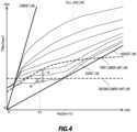
- FIG. 3 is a diagram illustrating a relationship between the state of GPF 12 and the operation mode of the engine 1.
- FIG. 4 is a shift map of the automatic transmission 2.
- the operation mode of the engine 1 is the normal mode.
- the region B of FIG. 3 is a region where the density of the PM deposited on the GPF 12 (hereinafter, referred to as "PM deposition density") is equal to or higher than a predetermined density D1, and the GPF temperature is equal to or lower than a predetermined first temperature T1.
- the operation mode of the engine 1 is set to a warming mode in which ignition retardation of the engine 1 is executed, and the lower limit (first lower limit) is set for the engine revolution speed to increase the GPF temperature.
- the fuel cut of the engine 1 is executed when the accelerator is off.
- the shift control of the variator 8 is performed such that the target rotation speed TNpri of the primary pulley 8a does not fall below the first lower limit line of FIG. 4 .
- the PM deposition density is equal to or higher than the density D1
- the exhaust temperature of the engine 1 increases, and the GPF temperature actively increases up to the PM combustion temperature or higher by executing ignition retardation and setting the lower limit (first lower limit) for the engine revolution speed to increase a workload of the engine 1.
- the specific density D1 is set depending on the specification of the vehicle. Note that it is also possible to increase the GPF temperature by setting only one of the ignition retardation and the lower limit setting of the engine revolution speed.
- the region C in FIG. 3 is a region where the GPF temperature is equal to or higher than a predetermined second temperature T2.
- the operation mode of the engine 1 is a fuel cut prohibition mode in which the fuel cut of the engine 1 is not executed even when the accelerator is off.
- a lower limit (second lower limit) is set for the engine revolution speed.
- the shift control of the variator 8 is performed such that the target rotation speed TNpri of the primary pulley 8a does not fall below the second lower limit line of FIG. 4 .
- the GPF temperature is equal to or higher than the second temperature T2
- the fuel cut is executed
- the GPF temperature increases due to the combustion of the PM, which may cause thermal deterioration of the GPF 12.
- the fuel cut prohibition mode even when the accelerator is off, the fuel cut of the engine 1 is not executed, so that the combustion of the PM is suppressed.
- the second temperature T2 decreases. This is because the higher PM deposition density further promotes combustion of the PM, which increases the GPF temperature.
- the second temperature T2 may be constant regardless of the PM deposition density.
- the second lower limit is set such that the engine revolution speed becomes higher than the specific low rotation speed region. As a result, it is possible to suppress the rattling noise from the drive system.
- the lower limit of the engine revolution speed even in the accelerator on state, it is possible to smoothly advance to the fuel cut prohibition state when the accelerator becomes off.
- FIG. 5 is a functional block diagram illustrating the engine controller 20.
- the engine controller 20 includes a density estimation unit 21 that estimates the PM deposition density, a temperature estimation unit 22 that estimates the GPF temperature, a mode setting unit 23 that sets the operation mode of the engine 1, an engine control unit 24 that controls an ignition timing of a spark plug, a fuel injection amount from the injector, and the like, and a lower limit setting unit 25 that sets the lower limit of the engine revolution speed (including the first lower limit and the second lower limit).
- each function of the engine controller 20 is illustrated as a virtual unit, which does not mean a physical existence.
- the microcomputer corresponding to each function may also exist physically.
- the engine controller 20 may include a first microcomputer having the functions of the density estimation unit 21, the temperature estimation unit 22, and the mode setting unit 23, a second microcomputer having the function of the engine control unit 24, and a third microcomputer having the function of the lower limit setting unit 25.
- the engine controller 20 receives signals input from the accelerator position sensor 41, the rotation speed sensor 42, the vehicle speed sensor 43, the differential sensor 44, the temperature sensor 45, the temperature sensor 46, and the like.
- the density estimation unit 21 estimates the PM deposition density on the basis of, for example, the differential pressure Pd detected by the differential sensor 44. Without limiting thereto, the estimation of PM deposition density may be performed by various methods known in the art.
- the temperature estimation unit 22 estimates the GPF temperature on the basis of, for example, the exhaust temperature Ti detected by the temperature sensor 45 and the exhaust temperature To detected by the temperature sensor 46. Without limiting thereto, the GPF temperature may be estimated by various methods known in the art.
- the mode setting unit 23 sets the operation mode of the engine 1 by executing the mode setting process.
- FIG. 6 is a flowchart illustrating the mode setting process in details.
- the mode setting process is executed at regular intervals.
- step S11 the mode setting unit 23 determines whether or not the GPF temperature estimated by the temperature estimation unit 22 is equal to or higher than the second temperature T2.
- the second temperature T2 used in the determination of step S11 is set depending on the PM deposition density estimated by the density estimation unit 21.
- step S12 If the mode setting unit 23 determines that the GPF temperature is equal to or higher than the second temperature T2, the process advances to step S12. Otherwise, if the mode setting unit 23 determines that the GPF temperature is lower than the second temperature T2, the process advances to step S13.
- step S12 the mode setting unit 23 sets the operation mode of the engine 1 to the fuel cut prohibition mode.
- step S14 If the mode setting unit 23 determines that the accelerator is off, the process advances to step S14. Otherwise, if the mode setting unit 23 determines that the accelerator is on, the process advances to step S15.
- step S14 the mode setting unit 23 determines whether or not the current operation mode of the engine 1 is the fuel cut prohibition mode.
- step S12 determines that the current operation mode of the engine 1 is the fuel cut prohibition mode
- step S15 determines that the current operation mode of the engine 1 is not the fuel cut prohibition mode
- step S11 YES
- step S13 YES
- step S12 YES
- steps S13 and S14 may not be processed. If steps S13 and S14 are not processed, and the mode setting unit 23 determines in step S11 that the GPF temperature is lower than the second temperature T2, the process advances to step S15.
- step S15 the mode setting unit 23 determines whether or not the GPF temperature estimated by the temperature estimation unit 22 is equal to or lower than the first temperature T1.
- step S16 If the mode setting unit 23 determines that the GPF temperature is equal to or lower than the first temperature T1, the process advances to step S16. Otherwise, if the mode setting unit 23 determines that the GPF temperature is higher than the first temperature T1, the process advances to step S18.
- step S16 the mode setting unit 23 determines whether or not the PM deposition density estimated by the density estimation unit 21 is equal to or higher than the density D1.
- step S17 If the mode setting unit 23 determines that the PM deposition density is equal to or higher than the density D 1, the process advances to step S17. Otherwise, if the mode setting unit 23 determines that the PM deposition density is lower than the density D1, the process advances to step S18.
- step S17 the mode setting unit 23 sets the operation mode of the engine 1 to the warming mode.
- step S18 the mode setting unit 23 sets the operation mode of the engine 1 to the normal mode.
- the mode setting unit 23 executes the mode setting process and sets the operation mode of the engine 1 to any of the normal mode, the warming mode, and the fuel cut prohibition mode.
- the engine control unit 24 controls the ignition timing of the spark plug, the fuel injection amount from the injector, and the like on the basis of the operation mode of the engine 1 set by the mode setting unit 23.
- the lower limit setting unit 25 executes the lower limit setting process to set the lower limit (including the first lower limit and the second lower limit) of the engine revolution speed.
- FIG. 7 is a flowchart illustrating the lower limit setting process in details.
- the lower limit setting process is executed at regular intervals.
- step S23 If the lower limit setting unit 25 determines that the accelerator is off, the process advances to step S23. Otherwise, if the lower limit setting unit 25 determines that the accelerator is on, the process advances to step S22.
- step S22 the lower limit setting unit 25 updates the operation mode of the engine 1 stored in the RAM. Specifically, the lower limit setting unit 25 reads the operation mode set in the mode setting unit 23 and stores it in the RAM.
- step S23 the lower limit setting unit 25 determines whether or not the operation mode stored in the RAM is the fuel cut prohibition mode.
- step S24 If the lower limit setting unit 25 determines that the operation mode stored in the RAM is the fuel cut prohibition mode, the process advances to step S24. Otherwise, if the lower limit setting unit 25 determines that the operation mode stored in the RAM is not the fuel cut prohibition mode, the process advances to step S25.
- step S24 the lower limit setting unit 25 sets the second lower limit as the lower limit of the engine revolution speed.
- step S25 the lower limit setting unit 25 determines whether or not the operation mode stored in the RAM is the warming mode.
- step S26 If the lower limit setting unit 25 determines that the operation mode stored in the RAM is the warming mode, the process advances to step S26. Otherwise, if the lower limit setting unit 25 determines that the operation mode stored in the RAM is not the warming mode, the process advances to step S27.
- step S26 the lower limit setting unit 25 sets the first lower limit as the lower limit of the engine revolution speed.
- step S27 the lower limit setting unit 25 sets a normal control. Under the normal control, the engine revolution speed is not limited. When the lower limit of the engine revolution speed has already been set, the lower limit setting is canceled by the process of step S27.
- the lower limit setting unit 25 sets the lower limit of the engine revolution speed by executing the lower limit setting process.
- the transmission controller 30 controls the shift of the variator 8 such that the target rotation speed TNpri of the primary pulley 8a does not fall below the first lower limit line of FIG. 4 .
- the transmission controller 30 controls the shift of the variator 8 such that the target rotation speed TNpri of the primary pulley 8a does not fall below the second lower limit line of FIG. 4 .
- the transmission controller 30 When the normal control is set by the lower limit setting unit 25, the transmission controller 30 performs the shift control of the variator 8 on the basis of the shift map of FIG. 4 .
- the operation mode update process (step S22) is not performed. Therefore, the lower limit setting of the engine revolution speed set for the accelerator off state continues until the accelerator becomes on.
- the first lower limit setting continues in the lower limit setting process.
- the second lower limit setting continues in the lower limit setting process.
- the target rotation speed TNpri is changed to the rotation speed determined by the coast line from the rotation speed determined by the first lower limit line. Therefore, the engine revolution speed may change abruptly, which may affect the operability of the vehicle 100.
- the target rotation speed TNpri is changed from the rotation speed determined by the second lower limit line to the rotation speed determined by the coast line as indicated by the arrow B. Therefore, the engine revolution speed may change abruptly, which may affect the operability of the vehicle 100.
- the lower limit setting set in the accelerator off state continues until the accelerator becomes on. Then, when the accelerator becomes on, the setting is changed depending on the operation mode of the engine 1 at that time.
- the accelerator becomes on, the target rotation speed TNpri subsequent to cancellation of the lower limit setting becomes a rotation speed higher than that determined by the coast line. Therefore, as compared with the case where the lower limit setting is canceled in the accelerator off state, an abrupt change of the engine revolution speed is suppressed, and it is possible to reduce influence on the operability of the vehicle 100 caused by the cancellation of the lower limit setting.
- the accelerator since the accelerator is on, it can be said that the driver expects a change in mobility of the vehicle 100. Therefore, even when the engine revolution speed changes abruptly, it is unlikely that the driver feels uncomfortable as long as it is not significant.
- the engine controller 20 of the vehicle 100 provided with the GPF 12 that collects the PM contained in the exhaust gas from the engine 1 sets the lower limit (including the first lower limit and the second lower limit) for the engine revolution speed.
- the lower limit of the engine revolution speed is set, and then, the GPF temperature increases over the first temperature T1 from the first temperature T1 or lower or decreases below the second temperature T2 from the second temperature T2 or higher, the lower limit setting of the engine revolution speed continues until the accelerator becomes on.
- the engine controller 20 executes the fuel cut of the engine 1. If the GPF temperature is equal to or higher than the second temperature T2, the fuel cut is prohibited even when the accelerator is off.
- the engine controller 20 continues to prohibit the fuel cut even when the GPF temperature falls below the second temperature T2 while the fuel cut is prohibited in the accelerator off state.
- the engine controller 20 sets the first lower limit for the engine revolution speed and executes ignition retardation of the engine 1 when the density of PM in the GPF 12 is equal to or higher than the density D 1, and the GPF temperature is equal to or lower than the first temperature T1.
- the first temperature T1 and the second temperature T2 are set such that the region B and the region C do not overlap with each other.
- the first temperature T1 may be set such that the region B and the region C overlap with each other.
- the mode setting unit 23 may determine whether or not the state of the GPF 12 is in the overlapping region between the region B and the region C, and the operation mode of the engine 1 may be selected and set such that any higher one of the first lower limit and the second lower limit of the engine revolution speed is set depending on the vehicle speed Vsp.
- the lower limit setting of the engine revolution speed set in the accelerator off state continues until the accelerator becomes on.
- the lower limit setting may be canceled when the operation mode of the engine 1 becomes the normal mode even in the accelerator off state.
- a predetermined condition for example, a condition that the differential rotation of the target rotation speed TNpri before and after cancellation of the lower limit setting is equal to or lower than a predetermined value may be employed.
- the engine controller 20 and the transmission controller 30 are individually provided. However, instead of providing the engine controller 20 and the transmission controller 30 individually, an integrated controller having both functions may be provided. Furthermore, the function of the engine controller 20 may be distributed to the transmission controller 30 or another controller (not shown). This similarly applies to the transmission controller 30.
Landscapes
- Engineering & Computer Science (AREA)
- Chemical & Material Sciences (AREA)
- Mechanical Engineering (AREA)
- Combustion & Propulsion (AREA)
- General Engineering & Computer Science (AREA)
- Automation & Control Theory (AREA)
- Transportation (AREA)
- Human Computer Interaction (AREA)
- Toxicology (AREA)
- Chemical Kinetics & Catalysis (AREA)
- Health & Medical Sciences (AREA)
- Materials Engineering (AREA)
- Electrical Control Of Air Or Fuel Supplied To Internal-Combustion Engine (AREA)
- Combined Controls Of Internal Combustion Engines (AREA)
- Processes For Solid Components From Exhaust (AREA)
- Control Of Vehicle Engines Or Engines For Specific Uses (AREA)
Abstract
Description
- The present invention relates to a vehicle control method and a vehicle control device.
-
JP2020-12404A - In the vehicle provided with the GPF, for example, for the purpose of suppressing generation of a rattling noise from a drive system by prohibiting the fuel cut as described above, raising the GPF temperature to promote a regeneration process of the GPF, and the like, it is conceivable to set a lower limit for an engine revolution speed on the basis of the GPF temperature.
- However, when the lower limit is set for the engine revolution speed, and the lower limit setting is canceled depending on a temperature change of the GPF, the engine revolution speed may abruptly change and affect operability of the vehicle.
- In view of such technical problems, it is therefore an object of the present invention to reduce influence on the operability of the vehicle caused by cancellation of the lower limit setting while the lower limit for the engine revolution speed is set on the basis of the GPF temperature.
- According to one aspect of the present invention, a vehicle control method for a vehicle provided with a gasoline particulate filter that collects particulate matter contained in an exhaust gas from an engine is provided. The vehicle control method includes: setting a lower limit for an engine revolution speed when an accelerator is off while a temperature of the gasoline particulate filter is equal to or lower than a predetermined first temperature or equal to or higher than a predetermined second temperature, the predetermined second temperature being higher than the predetermined first temperature; and continuing the lower limit setting for the engine revolution speed until the accelerator becomes on when the temperature of the gasoline particulate filter increases over the predetermined first temperature from the predetermined first temperature or lower or decreases below the predetermined second temperature from the predetermined second temperature or higher after the lower limit for the engine revolution speed is set.
-
-
FIG. 1 is a schematic configuration diagram illustrating a main configuration of a vehicle according to an embodiment of the present invention. -
FIG. 2 is a schematic configuration diagram illustrating a main configuration of an engine exhaust system. -
FIG. 3 is a diagram illustrating a relationship between a GPF state and an engine operation mode. -
FIG. 4 is a shift map of an automatic transmission. -
Fig. 5 is a functional block diagram illustrating an engine controller. -
FIG. 6 is a flowchart illustrating a mode setting process. -
FIG. 7 is a flowchart illustrating a lower limit setting process. - Embodiments of the present invention will now be described with reference to the accompanying drawings.
-
FIG. 1 is a schematic configuration diagram illustrating a main configuration of avehicle 100 according to an embodiment of the present invention. - As shown in
FIG. 1 , thevehicle 100 has anengine 1, anautomatic transmission 2, areduction gear train 3, a differential unit 4,drive wheels 5, an engine controller (control device) 20 that controls theengine 1, and atransmission controller 30 that controls theautomatic transmission 2. - The
engine 1 is an internal combustion engine that uses gasoline as fuel. - The
automatic transmission 2 has atorque converter 6, aforward clutch 7, avariator 8, and a hydraulicpressure control circuit 9. - The
torque converter 6 has alockup clutch 6a. Thetorque converter 6 amplifies and outputs the torque input from theengine 1 by virtue of a torque amplification action in a disengaged state of thelockup clutch 6a, and transmits rotation of theengine 1 without a loss in an engaged state of thelockup clutch 6a. - The
forward clutch 7 is a hydraulic multi-plate clutch that connects or disconnects a power transmission path between theengine 1 and thedrive wheels 5, and is engaged when thevehicle 100 moves forward. Theforward clutch 7 can adjust a torque capacity (the maximum value of the torque that can be transmitted) by adjusting the hydraulic pressure supplied from the hydraulicpressure control circuit 9. Note that, although only theforward clutch 7 is illustrated inFIG. 1 , theautomatic transmission 2 also has a backward brake that is engaged when the vehicle moves backward. When the backward brake is engaged, the rotation of theengine 1 is reversed and input to thevariator 8. - The
variator 8 is a continuously variable transmission mechanism including aprimary pulley 8a, asecondary pulley 8b, and abelt 8c hung therebetween. Thevariator 8 can change groove widths of each of thepulleys pressure control circuit 9. This makes it possible to change a speed ratio (input rotation speed/output rotation speed) in a stepless manner. - The rotation of the
engine 1 is changed by thevariator 8, and is transmitted to the left andright drive wheels 5 via thereduction gear train 3 and the differential unit 4. - The hydraulic
pressure control circuit 9 uses the hydraulic pressure of the hydraulic oil supplied from an oil pump (not shown) as a main pressure to regulate the hydraulic pressures supplied to thelockup clutch 6a, theforward clutch 7, the backward brake, theprimary pulley 8a, thesecondary pulley 8b, and the like and supply the regulated hydraulic pressure to each part. As a result, the engagement state of thelockup clutch 6a, the engagement state of theforward clutch 7, the engagement state of the backward brake, and the speed ratio of thevariator 8 are changed. - The
engine controller 20 includes a microcomputer provided with a CPU, a RAM, a ROM, an input/output interface, and the like. Theengine controller 20 performs various processes by reading and executing the program stored in the ROM by the CPU. Theengine controller 20 may also include a plurality of microcomputers. - The
engine controller 20 receives signals input from anaccelerator position sensor 41 that detects an accelerator position APO, arotation speed sensor 42 that detects a rotation speed Npri (= engine revolution speed) of theprimary pulley 8a, avehicle speed sensor 43 that detects a vehicle speed Vsp, and the like. Theengine controller 20 controls an ignition timing of a spark plug, a fuel injection amount from an injector, and the like on the basis of the input signals. Theengine controller 20 will be described in more details below. - The
transmission controller 30 includes a microcomputer provided with a CPU, a RAM, a ROM, an input/output interface, and the like, and is communicatably connected to theengine controller 20. Thetransmission controller 30 performs various processes by reading and executing the program stored in the ROM by the CPU. Thetransmission controller 30 may also include a plurality of microcomputers. - The
transmission controller 30 controls the engagement state of thelockup clutch 6a, the engagement state of theforward clutch 7, the engagement state of the backward brake, and the speed ratio of thevariator 8 via the hydraulicpressure control circuit 9. - Next, an exhaust system of the
engine 1 will be described with reference toFIG. 2. FIG. 2 is a schematic configuration diagram illustrating a main configuration of the exhaust system of theengine 1. - As shown in
FIG. 2 , anexhaust passage 10 is connected to theengine 1. Theexhaust passage 10 includes acatalyst converter 11, a gasoline particulate filter (GPF) 12, amuffler 13, adifferential pressure sensor 44 that detects a differential pressure Pd between the upstream side and the downstream side of theGPF 12, atemperature sensor 45 that detects an exhaust temperature Ti at the inlet of theGPF 12, and atemperature sensor 46 that detects an exhaust temperature To at the outlet of theGPF 12. - The
catalyst converter 11 internally has an exhaust gas purification catalyst such as a three-way catalyst and is arranged on the upstream side of theGPF 12. Thecatalytic converter 11 purifies the exhaust gas by oxidizing unburned components such as HC and CO contained in the exhaust gas of theengine 1 or reducing oxidizing components such as NOx. The catalyst converter may also be arranged in the downstream side of theGPF 12. - The
GPF 12 is a filter that collects particulate matter (PM) in the exhaust gas of theengine 1. - The
muffler 13 is provided in the downstream side of theGPF 12 to reduce the exhaust noise of the passing exhaust gas. - In the configuration described above, the exhaust gas from the
engine 1 flows through theexhaust passage 10, and is purified by thecatalyst converter 11. In addition, the PM is removed by theGPF 12, and the exhaust gas is then discharged to the outside from themuffler 13. - Meanwhile, since the
GPF 12 may be clogged as the PM is accumulated, it is necessary to burn the PM accumulated in theGPF 12 at an appropriate timing to regenerate theGPF 12. - The regeneration process of the
GPF 12 will now be described with reference toFIGS. 3 and4 . -
FIG. 3 is a diagram illustrating a relationship between the state ofGPF 12 and the operation mode of theengine 1.FIG. 4 is a shift map of theautomatic transmission 2. - In the region A of
FIG. 3 , the operation mode of theengine 1 is the normal mode. - In the normal mode, when the accelerator is off (APO=0), the fuel cut of the
engine 1 is executed. As a result, the air is sent to theGPF 12, so that when the floor temperature of the GPF 12 (hereinafter, referred to as "GPF temperature") rises over the PM combustion temperature at which the PM begins to burn, the combustion of the PM is promoted by the heat of theGPF 12 and the supplied oxygen. - The region B of
FIG. 3 is a region where the density of the PM deposited on the GPF 12 (hereinafter, referred to as "PM deposition density") is equal to or higher than a predetermined density D1, and the GPF temperature is equal to or lower than a predetermined first temperature T1. In the region B, the operation mode of theengine 1 is set to a warming mode in which ignition retardation of theengine 1 is executed, and the lower limit (first lower limit) is set for the engine revolution speed to increase the GPF temperature. In the warming mode, the fuel cut of theengine 1 is executed when the accelerator is off. - When the first lower limit is set as a lower limit of the engine revolution speed, the shift control of the
variator 8 is performed such that the target rotation speed TNpri of theprimary pulley 8a does not fall below the first lower limit line ofFIG. 4 . - If the PM deposition density is equal to or higher than the density D1, it is necessary to burn the PM deposited before the PM deposition density reaches the upper limit Dmax to prevent clogging of the
GPF 12. For this reason, in the warming mode, the exhaust temperature of theengine 1 increases, and the GPF temperature actively increases up to the PM combustion temperature or higher by executing ignition retardation and setting the lower limit (first lower limit) for the engine revolution speed to increase a workload of theengine 1. The specific density D1 is set depending on the specification of the vehicle. Note that it is also possible to increase the GPF temperature by setting only one of the ignition retardation and the lower limit setting of the engine revolution speed. - The region C in
FIG. 3 is a region where the GPF temperature is equal to or higher than a predetermined second temperature T2. In the region C, the operation mode of theengine 1 is a fuel cut prohibition mode in which the fuel cut of theengine 1 is not executed even when the accelerator is off. In the fuel cut prohibition mode, a lower limit (second lower limit) is set for the engine revolution speed. - When the second lower limit is set as a lower limit of the engine revolution speed, the shift control of the
variator 8 is performed such that the target rotation speed TNpri of theprimary pulley 8a does not fall below the second lower limit line ofFIG. 4 . - When the GPF temperature is equal to or higher than the second temperature T2, and the fuel cut is executed, the GPF temperature increases due to the combustion of the PM, which may cause thermal deterioration of the
GPF 12. In comparison, in the fuel cut prohibition mode, even when the accelerator is off, the fuel cut of theengine 1 is not executed, so that the combustion of the PM is suppressed. - As the PM deposition density increases, the second temperature T2 decreases. This is because the higher PM deposition density further promotes combustion of the PM, which increases the GPF temperature. Alternatively, the second temperature T2 may be constant regardless of the PM deposition density.
- When the fuel cut is prohibited in the accelerator off state, and the engine revolution speed is in a specific low rotation speed region, a rattling noise may occur from the drive system. Therefore, in the fuel cut prohibition mode, the second lower limit is set such that the engine revolution speed becomes higher than the specific low rotation speed region. As a result, it is possible to suppress the rattling noise from the drive system. In addition, by limiting the lower limit of the engine revolution speed even in the accelerator on state, it is possible to smoothly advance to the fuel cut prohibition state when the accelerator becomes off.
- Next, the
engine controller 20 will be described with reference toFIG. 5. FIG. 5 is a functional block diagram illustrating theengine controller 20. - As shown in
FIG. 5 , theengine controller 20 includes adensity estimation unit 21 that estimates the PM deposition density, atemperature estimation unit 22 that estimates the GPF temperature, amode setting unit 23 that sets the operation mode of theengine 1, anengine control unit 24 that controls an ignition timing of a spark plug, a fuel injection amount from the injector, and the like, and a lowerlimit setting unit 25 that sets the lower limit of the engine revolution speed (including the first lower limit and the second lower limit). - In
FIG. 5 , each function of theengine controller 20 is illustrated as a virtual unit, which does not mean a physical existence. Alternatively, the microcomputer corresponding to each function may also exist physically. For example, theengine controller 20 may include a first microcomputer having the functions of thedensity estimation unit 21, thetemperature estimation unit 22, and themode setting unit 23, a second microcomputer having the function of theengine control unit 24, and a third microcomputer having the function of the lowerlimit setting unit 25. - The
engine controller 20 receives signals input from theaccelerator position sensor 41, therotation speed sensor 42, thevehicle speed sensor 43, thedifferential sensor 44, thetemperature sensor 45, thetemperature sensor 46, and the like. - The
density estimation unit 21 estimates the PM deposition density on the basis of, for example, the differential pressure Pd detected by thedifferential sensor 44. Without limiting thereto, the estimation of PM deposition density may be performed by various methods known in the art. - The
temperature estimation unit 22 estimates the GPF temperature on the basis of, for example, the exhaust temperature Ti detected by thetemperature sensor 45 and the exhaust temperature To detected by thetemperature sensor 46. Without limiting thereto, the GPF temperature may be estimated by various methods known in the art. - The
mode setting unit 23 sets the operation mode of theengine 1 by executing the mode setting process. - The mode setting process will now be described with reference to
FIG. 6. FIG. 6 is a flowchart illustrating the mode setting process in details. The mode setting process is executed at regular intervals. - In step S11, the
mode setting unit 23 determines whether or not the GPF temperature estimated by thetemperature estimation unit 22 is equal to or higher than the second temperature T2. The second temperature T2 used in the determination of step S11 is set depending on the PM deposition density estimated by thedensity estimation unit 21. - If the
mode setting unit 23 determines that the GPF temperature is equal to or higher than the second temperature T2, the process advances to step S12. Otherwise, if themode setting unit 23 determines that the GPF temperature is lower than the second temperature T2, the process advances to step S13. - In step S12, the
mode setting unit 23 sets the operation mode of theengine 1 to the fuel cut prohibition mode. - In step S13, the
mode setting unit 23 determines whether or not the accelerator is off (APO=0). - If the
mode setting unit 23 determines that the accelerator is off, the process advances to step S14. Otherwise, if themode setting unit 23 determines that the accelerator is on, the process advances to step S15. - In step S14, the
mode setting unit 23 determines whether or not the current operation mode of theengine 1 is the fuel cut prohibition mode. - If the
mode setting unit 23 determines that the current operation mode of theengine 1 is the fuel cut prohibition mode, the process advances to step S12. Otherwise, if themode setting unit 23 determines that the current operation mode of theengine 1 is not the fuel cut prohibition mode, the process advances to step S15. - Even when the GPF temperature falls below the second temperature T2 while the fuel cut is prohibited in the accelerator off state, a driver may feel uncomfortable due to a vehicle behavior different from that of the accelerator operation if the fuel cut is executed immediately.
- Therefore, according to the present embodiment, even when the GPF temperature falls below the second temperature T2 (step S11: YES) while the fuel cut is prohibited (step S13: YES) in the accelerator off state (step S12: YES), the fuel cut is prohibited continuously (step S12).
- Note that steps S13 and S14 may not be processed. If steps S13 and S14 are not processed, and the
mode setting unit 23 determines in step S11 that the GPF temperature is lower than the second temperature T2, the process advances to step S15. - In step S15, the
mode setting unit 23 determines whether or not the GPF temperature estimated by thetemperature estimation unit 22 is equal to or lower than the first temperature T1. - If the
mode setting unit 23 determines that the GPF temperature is equal to or lower than the first temperature T1, the process advances to step S16. Otherwise, if themode setting unit 23 determines that the GPF temperature is higher than the first temperature T1, the process advances to step S18. - In step S16, the
mode setting unit 23 determines whether or not the PM deposition density estimated by thedensity estimation unit 21 is equal to or higher than the density D1. - If the
mode setting unit 23 determines that the PM deposition density is equal to or higher than thedensity D 1, the process advances to step S17. Otherwise, if themode setting unit 23 determines that the PM deposition density is lower than the density D1, the process advances to step S18. - In step S17, the
mode setting unit 23 sets the operation mode of theengine 1 to the warming mode. - In step S18, the
mode setting unit 23 sets the operation mode of theengine 1 to the normal mode. - As described above, the
mode setting unit 23 executes the mode setting process and sets the operation mode of theengine 1 to any of the normal mode, the warming mode, and the fuel cut prohibition mode. - The
engine control unit 24 controls the ignition timing of the spark plug, the fuel injection amount from the injector, and the like on the basis of the operation mode of theengine 1 set by themode setting unit 23. - The lower
limit setting unit 25 executes the lower limit setting process to set the lower limit (including the first lower limit and the second lower limit) of the engine revolution speed. - The lower limit setting process will now be described with reference to
FIG. 7. FIG. 7 is a flowchart illustrating the lower limit setting process in details. The lower limit setting process is executed at regular intervals. - In step S21, the lower
limit setting unit 25 determines whether or not the accelerator is off (APO=0). - If the lower
limit setting unit 25 determines that the accelerator is off, the process advances to step S23. Otherwise, if the lowerlimit setting unit 25 determines that the accelerator is on, the process advances to step S22. - In step S22, the lower
limit setting unit 25 updates the operation mode of theengine 1 stored in the RAM. Specifically, the lowerlimit setting unit 25 reads the operation mode set in themode setting unit 23 and stores it in the RAM. - In step S23, the lower
limit setting unit 25 determines whether or not the operation mode stored in the RAM is the fuel cut prohibition mode. - If the lower
limit setting unit 25 determines that the operation mode stored in the RAM is the fuel cut prohibition mode, the process advances to step S24. Otherwise, if the lowerlimit setting unit 25 determines that the operation mode stored in the RAM is not the fuel cut prohibition mode, the process advances to step S25. - In step S24, the lower
limit setting unit 25 sets the second lower limit as the lower limit of the engine revolution speed. - In step S25, the lower
limit setting unit 25 determines whether or not the operation mode stored in the RAM is the warming mode. - If the lower
limit setting unit 25 determines that the operation mode stored in the RAM is the warming mode, the process advances to step S26. Otherwise, if the lowerlimit setting unit 25 determines that the operation mode stored in the RAM is not the warming mode, the process advances to step S27. - In step S26, the lower
limit setting unit 25 sets the first lower limit as the lower limit of the engine revolution speed. - In step S27, the lower
limit setting unit 25 sets a normal control. Under the normal control, the engine revolution speed is not limited. When the lower limit of the engine revolution speed has already been set, the lower limit setting is canceled by the process of step S27. - As described above, the lower
limit setting unit 25 sets the lower limit of the engine revolution speed by executing the lower limit setting process. - When the first lower limit is set in the lower
limit setting unit 25, thetransmission controller 30 controls the shift of thevariator 8 such that the target rotation speed TNpri of theprimary pulley 8a does not fall below the first lower limit line ofFIG. 4 . - When the second lower limit is set in the lower
limit setting unit 25, thetransmission controller 30 controls the shift of thevariator 8 such that the target rotation speed TNpri of theprimary pulley 8a does not fall below the second lower limit line ofFIG. 4 . - When the normal control is set by the lower
limit setting unit 25, thetransmission controller 30 performs the shift control of thevariator 8 on the basis of the shift map ofFIG. 4 . - Here, as described above, in the lower limit setting process, when the accelerator is off (APO=0), the operation mode update process (step S22) is not performed. Therefore, the lower limit setting of the engine revolution speed set for the accelerator off state continues until the accelerator becomes on.
- For example, even when the GPF temperature increases over the first temperature T1 from the first temperature T1 or lower in the accelerator off state, and the operation mode set by the
mode setting unit 23 changes from the warming mode to the normal mode, the first lower limit setting continues in the lower limit setting process. - In addition, even when the GPF temperature falls below the second temperature T2 from the second temperature T2 or higher in the accelerator off state, and the operation mode set in the
mode setting unit 23 changes from the fuel cut prohibition mode to the normal mode, the second lower limit setting continues in the lower limit setting process. - Considering a case where the first lower limit setting is canceled in the accelerator off state with reference to
FIG. 4 , for example, in the vehicle speed V1, as indicated by the arrow A, the target rotation speed TNpri is changed to the rotation speed determined by the coast line from the rotation speed determined by the first lower limit line. Therefore, the engine revolution speed may change abruptly, which may affect the operability of thevehicle 100. - When the second lower limit setting is canceled in the accelerator off state, the target rotation speed TNpri is changed from the rotation speed determined by the second lower limit line to the rotation speed determined by the coast line as indicated by the arrow B. Therefore, the engine revolution speed may change abruptly, which may affect the operability of the
vehicle 100. - In comparison, according to the present embodiment, the lower limit setting set in the accelerator off state continues until the accelerator becomes on. Then, when the accelerator becomes on, the setting is changed depending on the operation mode of the
engine 1 at that time. - As a result, as the accelerator becomes on, the target rotation speed TNpri subsequent to cancellation of the lower limit setting becomes a rotation speed higher than that determined by the coast line. Therefore, as compared with the case where the lower limit setting is canceled in the accelerator off state, an abrupt change of the engine revolution speed is suppressed, and it is possible to reduce influence on the operability of the
vehicle 100 caused by the cancellation of the lower limit setting. In addition, since the accelerator is on, it can be said that the driver expects a change in mobility of thevehicle 100. Therefore, even when the engine revolution speed changes abruptly, it is unlikely that the driver feels uncomfortable as long as it is not significant. - Note that, if the lower limit setting in the accelerator off state is canceled, for example, the shift control of the
variator 8 is performed such that the engine revolution speed slowly changes after the cancellation of the lower limit setting. Therefore, it is possible to reduce influence on the operability of thevehicle 100. - As described above, according to the present embodiment, when the accelerator is off, and the GPF temperature is equal to or lower than the first temperature T1 or equal to or higher than the second temperature T2 higher than the first temperature T1, the
engine controller 20 of thevehicle 100 provided with theGPF 12 that collects the PM contained in the exhaust gas from theengine 1 sets the lower limit (including the first lower limit and the second lower limit) for the engine revolution speed. When the lower limit of the engine revolution speed is set, and then, the GPF temperature increases over the first temperature T1 from the first temperature T1 or lower or decreases below the second temperature T2 from the second temperature T2 or higher, the lower limit setting of the engine revolution speed continues until the accelerator becomes on. - As a result, it is possible to reduce influence on the operability of the
vehicle 100 caused by cancellation of the lower limit setting while the lower limit for the engine revolution speed is set on the basis of the GPF temperature. - When the accelerator is off, the
engine controller 20 executes the fuel cut of theengine 1. If the GPF temperature is equal to or higher than the second temperature T2, the fuel cut is prohibited even when the accelerator is off. - As a result, since combustion of the PM is suppressed, it is possible to suppress thermal deterioration of the
GPF 12. - The
engine controller 20 continues to prohibit the fuel cut even when the GPF temperature falls below the second temperature T2 while the fuel cut is prohibited in the accelerator off state. - As a result, it is possible to prevent the driver from feeling uncomfortable due to a vehicle behavior different from that of the accelerator operation.
- The
engine controller 20 sets the first lower limit for the engine revolution speed and executes ignition retardation of theengine 1 when the density of PM in theGPF 12 is equal to or higher than thedensity D 1, and the GPF temperature is equal to or lower than the first temperature T1. - As a result, since the exhaust temperature of the
engine 1 increases, it is possible to actively increase the GPF temperature to the PM combustion temperature or higher. Therefore, it is possible to effectively perform the regeneration process of theGPF 12. - Although embodiments of the present invention have been described hereinbefore, the aforementioned embodiments are merely one of the application examples of the present invention, and are not intended to limit the technical scope to the specific configuration of the embodiments described above.
- For example, in the embodiment described above, as shown in
FIG. 3 , the first temperature T1 and the second temperature T2 are set such that the region B and the region C do not overlap with each other. However, as indicated by the two-dotted chain line, the first temperature T1 may be set such that the region B and the region C overlap with each other. - In this case, when the state of the
GPF 12 is in the overlapping region between the region B and the region C, it is conceivable to determine in advance which of the warming mode and the fuel cut prohibition mode should be set as the operation mode of theengine 1. From the viewpoint of protecting theGPF 12, it is preferable to set the fuel cut prohibition mode with higher priority. - In addition, for example, the
mode setting unit 23 may determine whether or not the state of theGPF 12 is in the overlapping region between the region B and the region C, and the operation mode of theengine 1 may be selected and set such that any higher one of the first lower limit and the second lower limit of the engine revolution speed is set depending on the vehicle speed Vsp. - In addition, according to the embodiment described above, the lower limit setting of the engine revolution speed set in the accelerator off state continues until the accelerator becomes on. However, if a predetermined condition that is considered to have a smaller effect on the operability of the
vehicle 100 is satisfied, the lower limit setting may be canceled when the operation mode of theengine 1 becomes the normal mode even in the accelerator off state. As the predetermined condition, for example, a condition that the differential rotation of the target rotation speed TNpri before and after cancellation of the lower limit setting is equal to or lower than a predetermined value may be employed. - In addition, according to the embodiment described above, the
engine controller 20 and thetransmission controller 30 are individually provided. However, instead of providing theengine controller 20 and thetransmission controller 30 individually, an integrated controller having both functions may be provided. Furthermore, the function of theengine controller 20 may be distributed to thetransmission controller 30 or another controller (not shown). This similarly applies to thetransmission controller 30.
Claims (5)
- A vehicle control method for a vehicle provided with a gasoline particulate filter that collects particulate matter contained in an exhaust gas from an engine, the vehicle control method comprising:setting a lower limit for an engine revolution speed when an accelerator is off while a temperature of the gasoline particulate filter is equal to or lower than a predetermined first temperature or equal to or higher than a predetermined second temperature, the predetermined second temperature being higher than the predetermined first temperature; andcontinuing the lower limit setting for the engine revolution speed until the accelerator becomes on when the temperature of the gasoline particulate filter increases over the predetermined first temperature from the predetermined first temperature or lower or decreases below the predetermined second temperature from the predetermined second temperature or higher after the lower limit for the engine revolution speed is set.
- The vehicle control method according to claim 1, whereina fuel cut of the engine is executed when the accelerator is off, andthe fuel cut is prohibited even in the accelerator off state when the temperature of the gasoline particulate filter is equal to or higher than the predetermined second temperature.
- The vehicle control method according to claim 2, wherein
a prohibition of the fuel cut continues even when the temperature of the gasoline particulate filter is lower than the predetermined second temperature during the prohibition of the fuel cut in the accelerator off state. - The vehicle control method according to any one of claims 1 to 3, wherein
the lower limit is set for the engine revolution speed, and ignition retardation of the engine is executed when a density of the particulate matter in the gasoline particulate filter is equal to or higher than a predetermined density while the temperature of the gasoline particulate filter is equal to or lower than the predetermined first temperature. - A vehicle control device for a vehicle provided with a gasoline particulate filter that collects particulate matter contained in an exhaust gas from an engine, the vehicle control device performing:setting a lower limit for an engine revolution speed when an accelerator is off while a temperature of the gasoline particulate filter is equal to or lower than a predetermined first temperature or equal to or higher than a predetermined second temperature, the predetermined second temperature being higher than the predetermined first temperature; andcontinuing the lower limit setting for the engine revolution speed until the accelerator becomes on when the temperature of the gasoline particulate filter increases over the predetermined first temperature from the predetermined first temperature or lower or decreases below the predetermined second temperature from the predetermined second temperature or higher after the lower limit for the engine revolution speed is set.
Applications Claiming Priority (1)
| Application Number | Priority Date | Filing Date | Title |
|---|---|---|---|
| PCT/JP2020/015799 WO2021205561A1 (en) | 2020-04-08 | 2020-04-08 | Vehicle control method and vehicle control device |
Publications (2)
| Publication Number | Publication Date |
|---|---|
| EP4134536A1 true EP4134536A1 (en) | 2023-02-15 |
| EP4134536A4 EP4134536A4 (en) | 2023-02-22 |
Family
ID=78023183
Family Applications (1)
| Application Number | Title | Priority Date | Filing Date |
|---|---|---|---|
| EP20930356.9A Withdrawn EP4134536A4 (en) | 2020-04-08 | 2020-04-08 | VEHICLE CONTROL METHOD AND VEHICLE CONTROL DEVICE |
Country Status (5)
| Country | Link |
|---|---|
| US (1) | US11879369B2 (en) |
| EP (1) | EP4134536A4 (en) |
| JP (1) | JP7201127B2 (en) |
| CN (1) | CN114174658B (en) |
| WO (1) | WO2021205561A1 (en) |
Family Cites Families (20)
| Publication number | Priority date | Publication date | Assignee | Title |
|---|---|---|---|---|
| JP3829699B2 (en) * | 2001-11-28 | 2006-10-04 | いすゞ自動車株式会社 | Exhaust gas purification system and its regeneration control method |
| JP4003768B2 (en) * | 2004-09-14 | 2007-11-07 | トヨタ自動車株式会社 | Exhaust gas purification system for internal combustion engine |
| DE102004000065A1 (en) * | 2004-12-07 | 2006-06-08 | Ford Global Technologies, LLC, A Subsidiary of Ford Motor Company, Dearborn | Controlling the regeneration of a particulate filter for an internal combustion engine comprises spatially resolved modeling of the combustion of particulates in the filter |
| EP1722082B1 (en) * | 2005-05-13 | 2008-10-29 | HONDA MOTOR CO., Ltd. | Exhaust emission control system for internal combustion engine and control method therefor |
| US8151557B2 (en) * | 2007-08-07 | 2012-04-10 | GM Global Technology Operations LLC | Electrically heated DPF start-up strategy |
| JP5270265B2 (en) * | 2008-09-03 | 2013-08-21 | ヤンマー株式会社 | diesel engine |
| US8327628B2 (en) * | 2009-09-29 | 2012-12-11 | Ford Global Technologies, Llc | Gasoline particulate filter regeneration and diagnostics |
| US8181452B2 (en) * | 2009-09-29 | 2012-05-22 | Ford Global Technologies, Llc | Particulate filter regeneration during engine shutdown |
| JP5366762B2 (en) * | 2009-11-04 | 2013-12-11 | 日野自動車株式会社 | Particulate filter regeneration method |
| JP5235229B2 (en) * | 2011-07-04 | 2013-07-10 | 株式会社小松製作所 | Particulate removal filter regeneration control device and regeneration control method therefor |
| US8904757B2 (en) * | 2012-01-17 | 2014-12-09 | GM Global Technology Operations LLC | System and method for controlling regeneration within an after-treatment component of a compression-ignition engine |
| JP2015140150A (en) * | 2014-01-30 | 2015-08-03 | トヨタ自動車株式会社 | hybrid vehicle |
| US10487715B2 (en) * | 2015-08-20 | 2019-11-26 | Ford Global Technologies, Llc | Regeneration of particulate filters in autonomously controllable vehicles |
| JP6506154B2 (en) * | 2015-10-28 | 2019-04-24 | トヨタ自動車株式会社 | Exhaust purification system for internal combustion engine |
| JP6451718B2 (en) * | 2016-11-08 | 2019-01-16 | トヨタ自動車株式会社 | Hybrid car |
| DE102017100892A1 (en) * | 2017-01-18 | 2018-07-19 | Volkswagen Aktiengesellschaft | Regeneration of a particulate filter or four-way catalytic converter in an exhaust system of an internal combustion engine |
| JP6528796B2 (en) * | 2017-02-28 | 2019-06-12 | トヨタ自動車株式会社 | Vehicle control device |
| FR3069279B1 (en) * | 2017-07-19 | 2019-08-02 | Psa Automobiles Sa | METHOD FOR STARTING A REGENERATION OF A PARTICLE FILTER |
| JP7102903B2 (en) * | 2018-04-25 | 2022-07-20 | トヨタ自動車株式会社 | In-vehicle control device |
| JP2020012404A (en) | 2018-07-17 | 2020-01-23 | マツダ株式会社 | Engine control device |
-
2020
- 2020-04-08 CN CN202080051278.5A patent/CN114174658B/en active Active
- 2020-04-08 WO PCT/JP2020/015799 patent/WO2021205561A1/en not_active Ceased
- 2020-04-08 EP EP20930356.9A patent/EP4134536A4/en not_active Withdrawn
- 2020-04-08 JP JP2022513763A patent/JP7201127B2/en active Active
- 2020-04-08 US US17/630,668 patent/US11879369B2/en active Active
Also Published As
| Publication number | Publication date |
|---|---|
| EP4134536A4 (en) | 2023-02-22 |
| US11879369B2 (en) | 2024-01-23 |
| JP7201127B2 (en) | 2023-01-10 |
| CN114174658A (en) | 2022-03-11 |
| US20220268187A1 (en) | 2022-08-25 |
| CN114174658B (en) | 2023-09-12 |
| JPWO2021205561A1 (en) | 2021-10-14 |
| WO2021205561A1 (en) | 2021-10-14 |
Similar Documents
| Publication | Publication Date | Title |
|---|---|---|
| KR100496459B1 (en) | Exhaust emission control device for internal combustion engine | |
| EP2066893B1 (en) | Limiting transmission function while in regeneration mode for a diesel particulate filter | |
| JP7139972B2 (en) | In-vehicle control device | |
| JP2019190375A (en) | On-vehicle control device | |
| JP2015031166A (en) | Exhaust gas purification device for internal combustion engine | |
| JP2014092102A (en) | Travel control device for vehicle | |
| JP4003768B2 (en) | Exhaust gas purification system for internal combustion engine | |
| US11879369B2 (en) | Vehicle control method and vehicle control device | |
| JP4862590B2 (en) | Exhaust purification device | |
| CN111169456B (en) | Vehicle-mounted control device | |
| JP2017210883A (en) | Vehicle control device | |
| JP7040415B2 (en) | In-vehicle control device | |
| WO2014027505A1 (en) | Control device and control method for vehicle | |
| JP2020070743A (en) | In-vehicle control device | |
| JP2023156705A (en) | Internal combustion engine control device | |
| US12535040B2 (en) | Control apparatus for vehicle | |
| JP4387294B2 (en) | Vehicle control device | |
| JP7711638B2 (en) | Vehicle control device | |
| JP7297395B2 (en) | Control device for internal combustion engine | |
| JP2022136551A (en) | Control device for lockup crutch and control method for lockup clutch | |
| JP2024020885A (en) | Vehicle control device | |
| JP6871775B2 (en) | Engine control unit | |
| JPH0659792B2 (en) | Integrated control device for automatic transmission and engine |
Legal Events
| Date | Code | Title | Description |
|---|---|---|---|
| STAA | Information on the status of an ep patent application or granted ep patent |
Free format text: STATUS: THE INTERNATIONAL PUBLICATION HAS BEEN MADE |
|
| PUAI | Public reference made under article 153(3) epc to a published international application that has entered the european phase |
Free format text: ORIGINAL CODE: 0009012 |
|
| STAA | Information on the status of an ep patent application or granted ep patent |
Free format text: STATUS: REQUEST FOR EXAMINATION WAS MADE |
|
| 17P | Request for examination filed |
Effective date: 20220117 |
|
| AK | Designated contracting states |
Kind code of ref document: A1 Designated state(s): AL AT BE BG CH CY CZ DE DK EE ES FI FR GB GR HR HU IE IS IT LI LT LU LV MC MK MT NL NO PL PT RO RS SE SI SK SM TR |
|
| A4 | Supplementary search report drawn up and despatched |
Effective date: 20230125 |
|
| RIC1 | Information provided on ipc code assigned before grant |
Ipc: F01N 3/023 20060101ALI20230119BHEP Ipc: F02D 43/00 20060101AFI20230119BHEP |
|
| DAV | Request for validation of the european patent (deleted) | ||
| DAX | Request for extension of the european patent (deleted) | ||
| STAA | Information on the status of an ep patent application or granted ep patent |
Free format text: STATUS: EXAMINATION IS IN PROGRESS |
|
| 17Q | First examination report despatched |
Effective date: 20231004 |
|
| STAA | Information on the status of an ep patent application or granted ep patent |
Free format text: STATUS: THE APPLICATION IS DEEMED TO BE WITHDRAWN |
|
| 18D | Application deemed to be withdrawn |
Effective date: 20251101 |