EP4134513B1 - System and method for permanent carbon dioxide sequestration using a renewable energy source - Google Patents
System and method for permanent carbon dioxide sequestration using a renewable energy source Download PDFInfo
- Publication number
- EP4134513B1 EP4134513B1 EP22175231.4A EP22175231A EP4134513B1 EP 4134513 B1 EP4134513 B1 EP 4134513B1 EP 22175231 A EP22175231 A EP 22175231A EP 4134513 B1 EP4134513 B1 EP 4134513B1
- Authority
- EP
- European Patent Office
- Prior art keywords
- injection
- carbon dioxide
- water
- well
- injection well
- Prior art date
- Legal status (The legal status is an assumption and is not a legal conclusion. Google has not performed a legal analysis and makes no representation as to the accuracy of the status listed.)
- Active
Links
Images




Classifications
-
- E—FIXED CONSTRUCTIONS
- E21—EARTH OR ROCK DRILLING; MINING
- E21B—EARTH OR ROCK DRILLING; OBTAINING OIL, GAS, WATER, SOLUBLE OR MELTABLE MATERIALS OR A SLURRY OF MINERALS FROM WELLS
- E21B43/00—Methods or apparatus for obtaining oil, gas, water, soluble or meltable materials or a slurry of minerals from wells
- E21B43/16—Enhanced recovery methods for obtaining hydrocarbons
- E21B43/164—Injecting CO2 or carbonated water
-
- C—CHEMISTRY; METALLURGY
- C01—INORGANIC CHEMISTRY
- C01F—COMPOUNDS OF THE METALS BERYLLIUM, MAGNESIUM, ALUMINIUM, CALCIUM, STRONTIUM, BARIUM, RADIUM, THORIUM, OR OF THE RARE-EARTH METALS
- C01F11/00—Compounds of calcium, strontium, or barium
- C01F11/18—Carbonates
- C01F11/181—Preparation of calcium carbonate by carbonation of aqueous solutions and characterised by control of the carbonation conditions
-
- C—CHEMISTRY; METALLURGY
- C01—INORGANIC CHEMISTRY
- C01F—COMPOUNDS OF THE METALS BERYLLIUM, MAGNESIUM, ALUMINIUM, CALCIUM, STRONTIUM, BARIUM, RADIUM, THORIUM, OR OF THE RARE-EARTH METALS
- C01F5/00—Compounds of magnesium
- C01F5/24—Magnesium carbonates
-
- E—FIXED CONSTRUCTIONS
- E21—EARTH OR ROCK DRILLING; MINING
- E21B—EARTH OR ROCK DRILLING; OBTAINING OIL, GAS, WATER, SOLUBLE OR MELTABLE MATERIALS OR A SLURRY OF MINERALS FROM WELLS
- E21B41/00—Equipment or details not covered by groups E21B15/00 - E21B40/00
- E21B41/005—Waste disposal systems
- E21B41/0057—Disposal of a fluid by injection into a subterranean formation
- E21B41/0064—Carbon dioxide sequestration
-
- Y—GENERAL TAGGING OF NEW TECHNOLOGICAL DEVELOPMENTS; GENERAL TAGGING OF CROSS-SECTIONAL TECHNOLOGIES SPANNING OVER SEVERAL SECTIONS OF THE IPC; TECHNICAL SUBJECTS COVERED BY FORMER USPC CROSS-REFERENCE ART COLLECTIONS [XRACs] AND DIGESTS
- Y02—TECHNOLOGIES OR APPLICATIONS FOR MITIGATION OR ADAPTATION AGAINST CLIMATE CHANGE
- Y02C—CAPTURE, STORAGE, SEQUESTRATION OR DISPOSAL OF GREENHOUSE GASES [GHG]
- Y02C20/00—Capture or disposal of greenhouse gases
- Y02C20/40—Capture or disposal of greenhouse gases of CO2
Definitions
- the present disclosure relates to a system and method for permanent carbon dioxide (CO 2 ) sequestration in peridotite rock formations. More specifically, the present disclosure relates to accelerating and controlling natural peridotite carbonation between peridotite and a source of carbon dioxide to be sequestered. The present disclosure also relates to methods for permanently sequestering carbon dioxide that is captured from industrial emissions, atmospheric air, or that contained in bodies of fluid. The present disclosure also relates to the use of renewable sources of energy for carbon capture plants and carbon storage process equipment.
- CO 2 permanent carbon dioxide
- CCS carbon capture and storage
- peridotite Because of its high concentration of Mg, tectonically exposed peridotite from the Earth's upper mantle, which is composed largely of the mineral olivine ((Mg, Fe)SiO 4 ), with lesser proportions of pyroxene minerals ((Mg, Fe, Ca)Si 2 O) and spinel ((Mg, Fe)(Cr, Al)O), and its hydrous alteration product serpentine (Mg 3 Si 2 O 5 (OH) 5 ), have been considered a promising reactant for conversion of atmospheric carbon dioxide to solid carbonate. Natural carbonation of peridotite has been found to be surprisingly rapid compared to other types of rocks.
- Mantle peridotite is ordinarily more than 6 km below the seafloor and is strongly out of equilibrium with air and water at the Earth's surface. Its exposure along large thrust faults and along tectonic plate boundaries creates a large reservoir of chemical potential energy. Despite the available chemical potential, engineering techniques for carbon sequestration have many challenges. Engineering solutions involve grinding peridotite to a fine powder, purifying carbon dioxide gas, using reaction vessels at elevated pressure, and/or heating reactants to 100 degrees Celsius or more, and this comes at a substantial financial and energy cost.
- US9193594B2 discloses methods and systems for enhancing rates of carbonation of peridotite both in situ and ex situ.
- the methods and systems include the following: fracturing a volume of peridotite; heating the volume of peridotite; injecting an adjustable flow of carbon dioxide into the volume of peridotite; injecting bicarbonate materials into the volume of peridotite; and forming carbonate with the volume of peridotite and the carbon dioxide in an exothermic reaction thereby generating a self-sustaining heat source, the heat source heating the volume of peridotite.
- US8524152B2 discloses methods and systems for enhancing rates of in situ carbonation of peridotite.
- the methods and systems include the following: fracturing a volume of peridotite in situ; heating the volume of peridotite in situ; injecting carbon dioxide into the volume of peridotite in situ; and forming carbonate in situ with the volume of peridotite and the carbon dioxide.
- US9266061B2 discloses a filter for treating CO 2 from a CO 2 -emitting industrial plant, taking advantage of the fact that peridotite igneous rocks (or material of similar chemical content: basalt, gabbro, dunite, amphibolites, artificially produced Ca, Mg oxides) which are abundant on and close to the Earth's surface, can absorb and contain CO 2 gases resultant from industrial activity. This chemical process occurs naturally but has not been utilized to capture high concentrations of CO 2 emitted into the atmosphere. Calcium and magnesium oxides of the peridotite react with CO 2 to form stable carbonate minerals.
- the invention enhances and expedites this natural process for the remediation of industrial pollutants such as CO 2 from the oil, gas, coal, cement/concrete and like CO 2 -emitting industries, and provides a resource for materials in construction (concrete), steel, aviation and agricultural and other industries.
- industrial pollutants such as CO 2 from the oil, gas, coal, cement/concrete and like CO 2 -emitting industries, and provides a resource for materials in construction (concrete), steel, aviation and agricultural and other industries.
- JP2007283279A discloses a global warming suppression technology for decomposing, insolubilizing, and/or purifying soil polluted by hazardous substances and pollutants such as waste products, and the like, suppressing pollutants at the levels or lower than environmental quality standards for soil over long periods, and naturally adsorbing and decomposing carbon dioxide in air via its reaction step during treatment.
- a pollutant treating agent containing non-calcinated peridotite as a principal component is used for separating and/or decomposing pollutants in addition to perform long-term in solubilization by adding and/or mixing light-burned magnesite, light-burned dolomite, fused phosphate, or calcined shell powder according to types of pollutant.
- the polluted area is purified.
- the agent absorbs a large amount of carbon dioxide in air during the step of using the agent, so that the agent has effects as a low-cost and low-environmental-load-type technique for suppressing global warming.
- CN108658104A discloses a magnesium sinking technique during a kind of peridotite ore production of magnesia, including processing steps such as ore dressing, grinding, purification and impurity removal, flotation processing, magnesium sinking processing, acid leach removal of impurities, flotation purifying, precipitate separation, to increase the purity and recovery rate of magnesia.
- the method is disclosed to provide a magnesia purity of up to 99.7% or more, and up to 89.7 94.2%.
- PCT/EP2020/064306 discloses a method and a system of abating carbon dioxide (CO 2 ) and/or hydrogen sulfide (H 2 S) in a geological reservoir.
- CO 2 carbon dioxide
- H 2 S hydrogen sulfide
- Water is pumped or transferred from a water source to an injection well.
- the gasses are merged with the water under conditions where the hydraulic pressure of the water is less than the pressure of CO 2 and/or H 2 S gas at the merging point.
- the water with CO 2 and/or H 2 S gas bubbles is transferred further downwardly at a certain velocity higher than the upward flow velocity of said CO 2 and/or H 2 S gas bubbles ensuring downward movement of gas bubbles resulting in full dissolution of said CO 2 and/or H 2 S in the water due to elevating pressure.
- the complete dissolution ensures a lowered pH of the water entering a geological (e.g. geothermal) reservoir which is needed to promote mineral reactions leading to CO 2 and H 2 S abatement.
- This abatement may be quantified by dissolving a tracer substance in a predetermined molar ratio to said dissolved CO 2 and/or H 2 S and monitored in a monitoring well.
- the present disclosure provides an efficient and controlled method for CO 2 mineralization into peridotite rocks using renewable energy.
- Peridotite rocks are known for comprising mostly silicate minerals such as olivine and pyroxene. These types of minerals are active in the presence of solubilized CO 2 producing various carbonate rocks.
- the present disclosure is based on the idea of injecting solubilized carbon dioxide (water-CO 2 mixture) into peridotite rock formations and creating efficient reaction pathways by manipulating the operation conditions (temperature and pressure) for the mineralization reaction to happen. Consequently, CO 2 be converted into magnesite (MgCO 3 ) and calcite (CaCO 3 ) and stored permanently in the rock formation in mineral form.
- MgCO 3 magnesite
- CaCO 3 calcite
- a first aspect relates to a method of carbon dioxide sequestration by in situ mineralization comprising the steps of
- said rock formation consists mainly of peridotite.
- said injection and observation wells have the same depth.
- said longitudinal perforations have a length (l) of at least 15 cm and the density of said perforations along the injection well tubing and, optionally, a well casing in the injection well, are chosen depending on the fluid flow rate at the permeable zones.
- said perforations are radially separated with a gap (R) of at least 15 cm in the well casing.
- said renewable energy source is selected from the group consisting of solar energy, wind energy, biofuel energy, hydroelectric power, geothermal energy and other green energy sources.
- said method further comprises recycling water recycled back to a storage tank.
- a high-pressure zone is created within said injection well below a packed off interval and a low-pressure zone is created during the recycling through the observation well.
- most of the carbon dioxide and water mixture flows from a high- to a low-pressure zone and most of the fluid volume of the water is recycled back through the observation well.
- at least 50 % of the injected water is recycled, more preferably between 80 % and 100 % of the water is recycled.
- a second aspect relates to a system for controlled enhancement of peridotite in situ mineralization, comprising:
- said packer module is an inflatable unit for hydraulic isolation of an injection interval at a predetermined depth in the injection well.
- the packer module is configured to be inflated one or more of an aqueous solution and a gas.
- system further comprises:
- the renewable energy source is a hybrid energy source selected from the group consisting of a solar energy module; a renewable energy storage module; a wind turbine; a source of hydroelectric power; a biofuel generator; and other renewable energy sources.
- said renewable energy source comprises one or more of: a solar photovoltaic panel; a solar inverter; a synchronized biofuel generator; an energy storage module; and control panels and switch gears.
- said renewable energy source provides power to on-surface and sub-surface modules.
- the gas dissolution module is installed on the surface for gas transfer of carbon dioxide into water prior to the injection well tubing.
- said gas dissolution module is configured to inject at a gas flow rate of a minimum of 15 litre per minute, a gas pressure of a minimum 8 bar, and a minimum temperature of 20°C.
- said gas dissolution module is configured to inject gas bubbles into a water flow in the well injection tubing of a size less than 100 micrometers into a water flow in the non-corrosive well injection tubing.
- said well casing is about 18 to 23 cm (7 to 9 inches) in diameter.
- said well casing comprises longitudinal perforations of a length (l) of at least 15 cm.
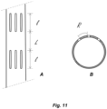
- Fig. 11 shows a longitudinal section of a well casing (A), as well as a cross section (B) of the same, indicating the length (l), and the longitudinal (L) and radial (R) spacing of the cut-outs.
- peridotite rocks contain two types of silicate minerals: olivine and pyroxene.
- Olivine rocks often contain magnesium, oxygen, and silicon. Olivine is the most abundant mineral in the earth's mantle until a depth of 700 km. The composition is usually a combination of SiO 4 and Mg 2+ .
- silicon bonds with 4 oxygen molecules forming a pyramid structure so that the charges of cations and anions are balanced, and Mg 2+ occupies the empty space between the SiO 4 structure. These bonds can be easily triggered to react with carbonic acid.
- the reaction of olivine with CO 2 can be accomplished by the following reaction pathway: MgSiO 4 + 2 CO 2 ⁇ 2 MgCO 3 + SiO 2 [1]
- Peridotite contains mainly the mineral's olivine and pyroxene.
- the following reaction occurs: Mg 2 SiO 4 (olivine) + CaMgSi 2 O 6 (pyroxene) + 2CO 2 + 2H 2 O -> Mg 3 Si 2 O 5 (OH) 4 (serpentine) + CaCO 3 (calcite) + MgCO 3 (magnesite)
- the present disclosure relates to a method that utilizes the above reaction pathways (especially equations 2 - 6) to convert and/or store CO 2 into peridotite rocks, as defined above, as a first aspect of the invention.
- the proposed method also enhances the above reaction rates leading to complete mineralization of total injected CO 2 volumes within two to twelve months from injection.
- the invention also discloses various operating conditions such as temperature, pressure, flowrate (depends on rock permeability), etc. that affect the process efficiency, and at which improved sequestration is obtained.
- Some embodiments of the present invention also cover engineering aspects such as utilizing renewable energy, water looping, and process configuration and design.
- Pyroxene is one of the groups in an inosilicate mineral, which is also abundantly found out in peridotite.
- the general chemical formula for pyroxene is AB(Si) 2 O 6 , in which A can be a cation such as sodium (Na + ), calcium (Ca 2+ ), manganese (Mn 2+ ), iron (Fe 2+ ), magnesium (Mg 2+ ), and lithium (Li + ), and B is calcium (Ca), sodium (Na), iron (Fell) or zinc (Zn), manganese (Mn) or lithium (Li) and B is manganese (Mn 2+ ), iron (Fe 2+ , Fe 3+ ), magnesium (Mg 2+ ), aluminum (Al 3+ ), chromium (Cr 3+ ), titanium (Ti 4+ ).
- A can be a cation such as sodium (Na + ), calcium (Ca 2+ ), manganese (Mn 2+ ), iron (Fe 2+ ), magnesium (Mg 2+ ), and lithium (Li + )
- B is calcium (Ca), sodium (
- pyroxene can often be found as CaMg(SiO 3 ) 2 .
- pyroxene reacts with CO 2 according to the following equation: CaMF(SiO 3 ) 2 + 2 CO 2 -> CaMg(CaCO 3 ) 2 + 2 SiO 2 [5]
- the system illustrates a carbon capture module (B), a system for accelerated in situ CO 2 mineralization (A), comprising an injection module (110), feeding CO 2 through a bore hole into a peridotite rock formation (P) where the process of mineralization takes place (M), a recovery system and a monitoring module (120), said system being powered by renewable energy from an energy generating and/or storage module (C), for example solar panels or generators operating on biofuel, to mention two non-limiting examples.
- a carbon capture module B
- A system for accelerated in situ CO 2 mineralization
- M peridotite rock formation
- M peridotite rock formation
- M a recovery system and a monitoring module
- C energy generating and/or storage module
- ambient air AA
- one or more chemicals capable of reacting with and trapping CO 2 for example potassium hydroxide
- the compressed CO 2 can be directly fed into the system (A) or stored and transported to an in situ mineralization site (A).
- some embodiments of the disclosed invention include a water looping system having a water storage module (210), a carbon dioxide injection module and injection well (220), a peridotite formation here schematically illustrated as a substantially horizontal layer (P), and an observation well module (230) for monitoring and controlling carbonation reactions.
- the process begins by identifying a suitable location with the peridotite layer being at least 0.5 km thick.
- An injection borehole is drilled into this peridotite layer. Said borehole should be at least 0.5 km deep and up to a maximum of 1.8 km in depth with the preferred depth being between 0.8 to 1.2 km deep.
- An observation borehole is drilled alongside the injection borehole with hydraulic connection between the two holes.
- the injection borehole is fitted with an engineered well casing (preferably steel or concrete) which is perforated at the targeted areas for peridotite mineralization in the geological formation (see FIG 11 and the text further below for more details).
- an engineered well casing preferably steel or concrete
- the buffer tank is fitted to receive water from different sources such as underground water resources, sea water, treated water etc.
- the water, at ambient temperature, is then pumped at pressure through the injection pipeline to the injection borehole well head by using a set of booster pumps.
- the formation temperature at 1 km depth is about 60 - 80°C. Pumping water to this formation will also help controlling the temperature at the site and, consequently, gives greater control over the reaction rate.
- a preferred embodiment of the invention utilizes water looping to minimize the consumption, loss and/or use of water during the CO 2 fixation process (sequestering).
- the water mass ratio of the amount of water injected into a subterranean geologic formation (e.g., a rock or peridotite formation) and the amount of water that is recovered at the recovery well (e.g., observation borehole, monitoring borehole or return well) is preferably close to 1: 1.
- Engineering the ingress point at which water injected into the borehole enters into the rock formation and/or engineering of a rock formation that with fissures or fractures functions to improve the overall recovery of water and reduces water loss.
- Water flow entering the geologic formation from the injection borehole can be directed by careful placement of longitudinal perforations in well tubing present inside the injection borehole or the casing surrounding the borehole in contact with the geologic formation.
- the perforations are disposed within a zone of injection that corresponds to a shortest distance direct line from the borehole wall of the injection borehole to the borehole wall of the return well.
- Perforations in the borehole are disposed in the casing of the borehole in only a single hemisphere of the borehole, e.g., the hemisphere encompassing the shortest distance direct borehole-borehole line. Disposing the perforations in this way functions to reduce unwanted or unintended flow of water in a direction away from the recovery well. Alignment of the perforations with fractures and fissures that are in hydraulic communication with the recovery well may also be favored.
- the longitudinal perforations preferably occur at depths in the injection borehole that are within the target zone of the geological formation proximal to an upper boundary. Additional perforations at progressively deeper borehole depths, but preferably in the same hemisphere, may extend downwardly into the borehole proximal to a maximum depth of the peridotite-containing rock formation.
- the recovery borehole preferably has a depth that is at least the same as the maximum depth of the perforations of the injection borehole. In other embodiments the recovery borehole has a depth that is deeper than the deepest perforation of the injection borehole such that water flowing by gravity will pool or collect at the deeper portions of the recovery borehole and thereby minimize water loss.
- the recovery borehole depth is no greater than the maximum depth of the rock formation that comprises mainly peridotite.
- Total dissolved solids of the water may decrease as the water passes through the rock formation.
- the recovery borehole collects water that is of greater purity the water (CO 2 rich fluid-mixture) initially injected into the injection borehole.
- Saline water, brackish water and/or seawater can have a reduced total solids content after flowing through the injection borehole, through the rock formation and recovery borehole.
- Water looping is likewise utilized in above ground handling and treatment of water, e.g., during processing of water collected in the recovery borehole prior to injection into the injection borehole.
- Preferably at least a majority of the water injected into the injection borehole is recycled or reused for later injection of additional CO 2 into the injection borehole.
- Preferably, all of the water obtained from the recovery borehole is used in the injection borehole after the addition of further CO 2 .
- Water looping in this manner minimizes the need to pre-purify water prior to injecting into the rock formation and maximizes the reuse and recycle of the water.
- the recovery borehole is preferably an uncased well so that water may more easily enter and collect in the recovering borehole.
- the recovery borehole is partially cased with at least a major portion of the borehole length that passes through the target zone remaining uncased. Partial casing of the recovery borehole reduces loss of water in strata above and/or below the target zone that may be porous and/or otherwise hydraulically communicate with other underground rock formations that do not permit recovery of water.
- the CO 2 rich fluid-mixture is injected into the geologic formation through the injection borehole at an ambient temperature preferably 25-30° C ⁇ 15°C, preferably ⁇ 10°C, more preferably ⁇ 5°C.
- ambient temperature preferably 25-30° C ⁇ 15°C, preferably ⁇ 10°C, more preferably ⁇ 5°C.
- cooler temperatures are capable of dissolving greater amounts of CO 2 .
- This aspect of the invention is particularly well-suited for evaporative cooling of the return fluid obtained from the recovery, observation or monitoring well.
- Fixation of the CO 2 in the CO 2 rich fluid-mixture injected into the geologic formation is, in a preferred embodiment, essentially complete.
- a CO 2 rich fluid-mixture injected into the injection borehole forms a return fluid collected at the return well (observation or monitoring borehole) having an amount of dissolved CO 2 that is less than 0.1 wt-%, preferably less than 0.05 wt-%, more preferably less than 0.01% by weight based on the total weight of the return fluid and the CO 2 .
- the return fluid may be completely free of CO 2 .
- the geologic formation is first subject to pretreatment with water or an aqueous solution before the CO 2 rich fluid-mixture is injected therein.
- Pretreatment with water or aqueous solution can enhance initial absorption and fixation of CO 2 .
- Treatment with an aqueous solution such as an aqueous acidic solution may enhance CO 2 absorption of fixation by forming voids and crevices within the geologic formation thereby providing enhanced fluid flow through the formation and/or otherwise activating the peridotite formation for reaction with CO 2 .
- Prior mechanical fracturing of the geologic formation is not required.
- the CO 2 rich fluid-mixture is injected into the geologic formation at pressures substantially less than those necessary in order to mechanically fracture the formation.
- CO 2 is dissolved in fluid on surface through a gas dissolution module into the pressurized water stream between the booster pumps and the injection well head.
- Artificial conservative tracer(s) are used to trace the injected CO 2 -saturate fluid within the storage reservoir utilizing the monitoring / observation boreholes. Molar ratio of tracers to CO 2 are kept constant at the injection well, whereas changes of this ratio in the observation borehole indicates CO 2 abatement via reaction with peridotite.
- the CO 2 gas is dissolved once it mixes with the pressurized water stream, where it is carried to the target injection zone.
- the gas pressure in the pressurized water stream is set to be below or close to the hydrostatic pressure at the target injection depth.
- the CO 2 rich fluid-mixture is then injected through the injection borehole well head.
- the injection well head is connected through a non-corrosive pipe to a packer system (312) that is installed just above the target injection zone.
- the packer system (312) hydraulically isolates the column for injection of CO 2 rich fluid-mixture into the peridotite rock formation.
- the injected CO 2 rich fluid-mixture is dispersed through the annulus within the peridotite formation where the dissolved CO 2 reacts in-situ with the peridotite rocks.
- the dispersion of the CO 2 -rich fluid mixture happens via perforated well casing which targets a specific pre-determined permeable layer of the peridotite.
- the CO 2 rich fluid-mixture is preferably injected into the borehole within the target zone by delivery through a steel or polymer tubing string.
- contact between the borehole wall and/or casing with the CO 2 rich fluid-mixture is minimized except for at a location where the borehole is perforated within the target zone of peridotite.
- the point at which the CO 2 rich fluid-mixture is released from the tubing string into the borehole can be determined by using packers at different depths or different positions within the borehole.
- packers are set both upstream and downstream of the injection point(s) within the injection borehole at which the CO 2 rich fluid-mixture is released from the tubing string into the borehole and through perforations in the borehole casing into the rock formation.
- a packer is set above the maximum depth of the target formation and below the minimum depth of the target formation to limit the release of the CO 2 rich fluid-mixture into the portion of the borehole which directly corresponds with and is encompassed by a peridotite rock formation.
- the return fluid formed when the CO 2 rich fluid-mixture e.g., CO 2 saturated water
- the geologic formation e.g., peridotite reservoir
- the return fluid is subject to cooling after return to the surface.
- a portion of the return water is used in an evaporative cooling process.
- the return fluid may flow through a manifold system in which the return fluid is divided into at least two portions.
- a main portion is piped to another location, for example, to a storage tank or directly to the well injection point for further mixing with CO 2 and later injection into the injection borehole.
- the second, typically smaller, portion is transferred to an evaporative cooling apparatus and evaporated.
- a return fluid pipe used for transferring the main portion of the return fluid may disposed in a second pipe of larger diameter forming an annulus space between the outer surface of the return fluid pipe and the inner surface of the second pipe.
- the second portion of the return water may then be sprayed or passed into the annulus in the presence of a stream of gas in which the second portion of the return fluid evaporates thereby providing cooling effect to cool the fluid in the return fluid pipe.
- the gas flow used in the evaporative cooling is CO 2 which may subsequently be transferred to a CO 2 storage facility and/or the well injection point for injection into the geological formation.
- the gas stream exiting the annulus includes evaporated water and mainly carbon dioxide gas.
- Injection of the CO 2 rich fluid-mixture into the injection well may be under conditions permitting effervescence of CO 2 from the CO 2 rich fluid-mixture.
- the formation of bubbles in the geologic formation may permit enhanced absorption and/or fixation through effects that include, for example, disruption of water flow as a two-phase mixture and collisions of CO 2 bubbles with features of the geologic formation surface.
- the hybrid-renewable system preferably includes a plurality of photovoltaic (PV) cells to generate electricity from sunlight.
- PV photovoltaic
- Electrical storage facilities are typically included.
- PV panels are preferably mounted over the injection system and over storage tanks. Especially with respect to mounting above the injection system, electrical energy obtained from the PV cells may be used directly thereby avoiding the complexities and expense of long electrical transfer lines.
- Portability especially as it relates to the injection system, is especially advantageous for relocation of the injection equipment and energy generating equipment to new locations of geologic material. As a geologic formation of peridotite becomes reacted/saturated with CO 2 , the efficiency of further CO 2 fixation decreases. It is then advantageous to seal the return fluid well (for example by cementing) and relocate injection of the CO2 rich fluid-mixture to an injection point located differently than an initial well.
- some embodiments of the disclosed subject matter include a continuous injection method and other embodiments show an overview of the CO 2 injection system.
- a submersible pump (SP2) is installed in the observation borehole at depth and is used to pump ground water into an on-surface storage tank (340).
- SP2 flow rates and pressures preferably match the permeability of the subsurface formation.
- the on-surface storage tank (340) is equipped with sensors that automate the operation of the SP2 and acts as a buffer between the observation and injection boreholes.
- the tank has a volume of at least 5000 L.
- the on-surface storage tank is also fitted with coupling connections to receive water from different other sources.
- a set of booster pumps (BP1, BP2) are used in parallel to inject water from the on-surface storage tank (340) at pressure to the injection well (320).
- the flow rates of the fluid-mixture are adapted to the permeability of the target injection zone at the injection borehole.
- a permeability test is carried out to determine these rates at the injection borehole prior to injecting CO 2 rich fluid-mixture.
- One or more dosing pumps (DP) is/are used to regulate the flow of a tracer fluid from a tracer tank (360).
- said tank has a volume of at least 100 l, and fluorescein is used as the tracer.
- the tracer is injected into the water stream at pressure, in the pipe section between the BPs and the injection well head, using a set of dosing pumps (DPs).
- the dosing rate is regulated throughout the injection process.
- the tracer fluid is used to trace the injected CO 2 rich fluid-mixture in the subsurface using observation boreholes (333).
- a gas dissolution module (310) is installed on a flanged pipe section, before the injection well head.
- CO 2 gas is injected at pressure into the water stream.
- CO 2 gas injection pressure is regulated by a mass flow controller device that is connected to a gas manifold. The gas manifold controls the supply of CO 2 gas from the CO 2 storage tanks at a regulated pressure level.
- the gas dissolution module is designed to maximize gas transfer efficiencies as well as buffer capacities within the injection pipe column and to release CO 2 gas bubbles at ⁇ 50 ⁇ m to maximize bubbles surface area for solubility and to reduce the buoyancy effect.
- the CO 2 rich fluid-mixture is injected into the subsurface through an injection well head on the injection borehole.
- the injection well head holds the string assembly that is suspended on a supported mechanical system on the surface.
- the string assembly is composed of (1) Non-corrosive fluid pipes that connect the injection well head on surface to the packer system (312) and acts as the injection column for the CO 2 rich fluid-mixture; (2) Submersible pump (SP1) placed on the injection borehole and connected on the string assembly used to pump back the injected CO 2 rich fluid-mixture any at given point during the injection process; (3) Shut-In-Tool (SIT, 311) that is used to isolate the injection interval once the CO 2 rich fluid-mixture is injected into peridotite formation which acts as a safety measure to prevent any undissolved CO 2 gas bubbles from rising back to the surface during any maintenance operations; and (4) packer system or packer module (PS) consists of a water or gas inflation packer that is used to pack off the interval at the target injection zones.
- SP1 Submersible pump
- SIT, 311 Shut-In-Tool
- PS packer system or packer module
- the packer is equipped with various sensors to monitor hydraulic pressures of the column above and below the packed off interval as well as the packer pressure.
- the PS is also set-up with other sensors for live monitoring of the injection zone interval.
- the interval is packed off at a differential to the column hydrostatic pressure ensuring a proper seal is maintained once hydraulic pressure below the packed off interval begins to increase.
- confirmation that CO 2 injected into the geological formation is absorbed and fixed can be determining by measuring the CO 2 /fluid ratio at the well injection point in comparison to the CO 2 /fluid ratio in the return fluid at a surface return site.
- the CO 2 injected into the geologic formation can be modified to include an amount of nucleotide-labeled material (for example CO 2 labeled with 17 O or CO 2 labeled with 14 C) and compared with a corresponding amount (concentration) in the return fluid.
- a fluid recovery well (330) for the return fluid can be located at a distance from the CO 2 injection well (320) such that the distance the CO 2 rich fluid mixture traverses through the geologic formation is sufficient to absorb and/or fixate substantially all of CO 2 in the CO 2 rich fluid-mixture.
- This distance may vary depending on the location of the injection well, the structure of the geologic formation and the availability of water for injecting the CO 2 rich fluid-mixture into the geologic formation.
- a distance of 0.1-10 km, preferably 0.2-5 km, 0.5-1 km or 0.7-0.9 km can be used.
- some embodiments of the disclosed subject matter include a renewable energy system that consists of for example, a solar cell module (410), solar inverters (420), an energy storage module comprising a battery system (460), an energy management system, EMS (470), wind turbines (not shown), and a biofuel module, comprising for example synchronized generators (440), a fuel tank (450) for holding biofuel. Further, switchgear (430) and an energy meter (480) is preferably included.
- the renewable energy system works in such a way that during daytime, solar energy is used to supply the loads to all injection systems on the ground. Excess renewable energy is stored to be used for improved system performance and for operation during night-time.
- the energy stored is used for supplying the required loads. Based on site consumption, the energy stored would be utilized to supply the night loads throughout the entire night period along with renewable energy sources that can operate at night (Eg; wind turbines and biofuel generators). There is no loss in power while transitioning from solar/off-grid operation to energy storage, the stored energy will instantly take over supply and smoothly transition to energy storage operation only.
- the hybrid controller will be responsible for communication among the inverters, storage, biofuel generators and the overall transfer of power within the system
- Another preferred embodiment of the present invention is the injection borehole (310, 320) development. This involves increasing wellbore diameter from 16.5 cm to 25 cm for the full depth of the borehole and permanent installation of non-corrosive casing, ideally 7-inch (17.78 cm) in diameter, with slotted sections or screen in the injection zone.
- Drilling Rate of Penetration can be used to interpret rock properties. A slower rate of penetration indicates a requirement for higher fracture stress by the drill bit to break the rock. For rock types that are known to be homogenous this information will serve as an indication for the level of porosity at different depths. Porosity reduces the fracture stress of bulk rock type and therefore increased ROP is indicative to higher porosity.
- downhole injection assembly system is described.
- a packer tool (312) is installed to isolate the injection interval from the remaining part of the borehole. This allows for installation of pressure monitoring devices above and below the packer tool (312).
- a shut-in tool (311) is installed to isolate the injection interval after injection to ensure no upward drift of injected fluid to the top intervals.
- the submersible pump (SP-1) is used to draw water from the isolated injection interval and for sampling purposes.
- Downhole injection piping and equipment are pressure rated to withstand injection pressures required.
- Well head installed constitutes of two ports: 1) Incoming injection fluid and 2) outgoing sampling port. It is noteworthy to mention that a check should carried out for any blockages and remove any existing blockages for the complete depth of the open borehole.
- a submersible intake pump (SP2) is used in the observation well (333).
- SP2 submersible intake pump
- a submersible pump is used to draw water from the observation well to be used for injection purposes in the injection borehole.
- the submersible pump is placed at least 60 mbgl to draw water from above the injection interval in injection borehole. This is done to minimize interference in the event of existing subsurface connectivity between the two wellbores.
- the submersible pump is sized on the following flow basis: provide a flow rate of a minimum of 0.1 L/s and a minimum of 8640 L/day under the recommended operating schedule.
- the submersible pump is sized on the following pressure basis: placement depth is a minimum of 60 mbgl (meters below ground level); pumping head must be sufficient to deliver water to surface at ease.
- Submersible pumps cannot operate continuously for extended period. Therefore, the observation well water will be supplied with temporarily stored water in a buffer tank to counteract the intermittent nature of submersible pumps.
- a water buffer tank In another preferred embodiment of the present invention a water buffer tank is described.
- the water buffer tank or tanks will hold water from observation wells or from another source to counteract pumping intermittency, flow intermittency, stabilize pressure and for additional process control and operational reasons.
- Sizing of the buffer tank is dependent on the selection of the submersible pump and is made on the following basis: 1) the tank holds sufficient capacity to allow the submersible pump to deliver the daily required volumes following the recommended hours of operation schedule; and 2) the tank should hold sufficient capacity to allow for continuous and uninterrupted draw of at least 0.1 L/s for injection.
- a buffer tank capacity of 5500 L was chosen.
- the buffer tank also plays a critical role of dampening pressure fluctuation caused by natural changes in water levels in the observation borehole and will therefore allow for a stable pressure supply by the injection pumps.
- the injection pump/s are selected for continuous and uninterrupted operation.
- the sizing of the pumps are made on the following basis: 1) flow rate set at a minimum of 0.1 L/s; 2) sufficient overpressure to cover hydrostatic head at the injection interval, major and minor head losses due to the system assembly, and account for pressure build up to allow flow through the injection zone is done through energy balance equation used to calculate head loss in system and Darcy's law used to determine flow into the injection zone by assuming linear cylindrical outward flow; and 3) provide a pressure high enough to ensure solubility of dissolved CO 2 on surface at steady state flow conditions.
- a dosing pump (DP1) is used to inject set volume (at least 5 mL/min) of liquid conservative tracers, e.g. fluorescein, into along with the injection fluid. Dosing is done inline after the injection pumps / booster pumps. Due to the dynamic changes in the subsurface pressure conditions after the start of injection flow rate is expected to change over time to reflect the change in conditions. The water flowmeter will record changes in the injected fluid flow rate over injection time to monitor the system behavior with respect to subsurface pressure and to allow for accurate accounting of total injected volumes and to assist with dynamic data interpretation.
- DP1 dosing pump
- an electromagnetic flow meter is selected for its uniform behavior, responsive reading time, un-interruption to flow and due to the homogenous nature of the injected fluid that allows for consistent magnetic behavior and therefore consistent flow reading accuracy.
- the flow meter is calibrated specifically for the project application to ensure the accuracy of the meter for the expected flow conditions.
- the Automatic CO 2 gas switchover manifold is used to stabilize and regulate the pressure from CO 2 tanks.
- CO 2 tank pressure gradually decreases as the contained gas is depleted and due to the sensitive thermodynamic behavior of gas temperature swings between day and night has a significant impact on tank supply pressure. Further the expansion of the gas through various valves and through the pipes also associate with temperature changes and consequently pressure changes.
- the manifold regulates the delivery pressure from tanks to a selected setpoint.
- the manifold also ensures uninterrupted CO 2 supply by operating one wing (301) and keeping the second wing (302) on standby.
- the gas flow controller will adjust the flow to account for all gas flow fluctuation to maintain a stable flow rate of a minimum of 1.3 g/s.
- a gas dissolution module is used to mix CO 2 into the water.
- a gas dissolution system (310) can be used to maximize the gas liquid contact surface area to minimize gas dissolution time and to ensure complete dissolution of CO 2 in the injected water.
- This system is placed after the injection pump as higher pressures promote higher gas solubility.
- the system is designed to dissolve gas with a bubble diameter less than 100 ⁇ m and is specifically designed and tuned for the project application accounting for both water and gas flow rates and pressures.
- the design of the system also accounts for the gas pressure drop across the system to balance with the maximum delivery pressure available from the manifold and additional pressure drops in the gas delivery system, to ensure flow into the high-pressure water line.
- the housing of the system is designed to accommodate all components with minimal interruption to water flow, provides easy internal access for servicing purposes and allows for slower flow velocity so that the dissolution residence time matches the fluid residence time in the unit.
- Monitoring includes a complete water quality testing, pH, total dissolved solids (TDS), electrical conductivity (EC), temperature, Oxidation Reduction Potential (ORP) and other physical properties.
- TDS total dissolved solids
- EC electrical conductivity
- ORP Oxidation Reduction Potential
- a sample from borehole water has been collected after drilling activity for complete water quality testing by an independent laboratory.
- a submersible pump placed at a minimum of 60 mbgl was used to collect water for pH, EC, TDS, Temperature and ORP on site.
- An additional submersible pump was placed at a minimum of 60 mbgl used to collect samples to test for cations, anions, alkalinity, and dissolved CO 2 .
- monitoring system also included the injected conservative tracers to monitor the change of the molar ratio of CO 2 to tracers, which was kept constant in the injection well. Changes in this ratio will indicate CO 2 -water-rock reactions and thus CO 2 abatement.
- natural tracers such as stable carbon, strontium, magnesium and calcium isotopes, it is possible to determine the reactivity of the peridotite system to mineralize the injected CO 2 .
- the fluid flow path between the injected borehole and the observation borehole are natural fractures that extend in other directions than upward or downward or in case of limiting natural fractures, a fracture network that has been induced through permeability enhancement.
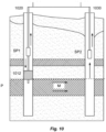
- FIGs 3 and 10 In a pilot scale experiment carried out in the Samail Ophiolites in the Sultanate of Oman and supervised by the inventors, a system was constructed as schematically shown in FIGs 3 and 10 . Two boreholes (1020, and 1030) were drilled into the rock until a peridotite layer (P) was reached. The first borehole (1020) was fitted with well casing which was perforated (See FIG 11 ) at the targeted areas for peridotite mineralization. A packer (1012) was used to isolate the peridotite layer (P) for targeted injection of the CO 2 - water mixture.
- a submersible pump (SP1) located in the borehole (1020) above the packer was used to recoup the injected fluid mixture after an incubation period for sampling and analysis, to prove occurrence of mineralization (M).
- a submersible pump (SP2), in the opposite borehole (1030), was used to pump groundwater for injection into the injection borehole.
- CO 2 was fully dissolved in the groundwater on the surface using a gas dissolution module (310) at a pre-defined CO 2 to water ratio.
- a conservative tracer here sodium fluorescein
- the CO 2 saturated fluid was injected via a non-corrosive pipe to the hydraulically isolated target injection interval in the first borehole (1020).
- a monitoring borehole (not shown) that was hydraulically connected to the injection borehole via a natural fracture network in the peridotite reservoir, was utilized for estimating the CO 2 mineralization capacity of said reservoir rock. Samples were also taken in the first borehole (1020) in an upper section above the packer (1012) peridotite layer (P).
- a monitoring equipment was used to monitor the degree of CO 2 abatement via peridotite-water reactions, utilizing the molar ratio of CO 2 to said conservative tracer.
- CO 2 mineralization could be quantified by monitoring the dissolved CO 2 content in the injected fluid and in the observation borehole via said membrane system. Decreased dissolved CO 2 concentration in the observation borehole fluids compared to the initial concentration in the injection borehole clearly indicated that an amount of CO 2 was sequestered.
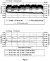
- the experiment was performed during a period of six days, and the measured results are shown in FIGs 5 - 9 .
Landscapes
- Chemical & Material Sciences (AREA)
- Life Sciences & Earth Sciences (AREA)
- Geology (AREA)
- Engineering & Computer Science (AREA)
- Organic Chemistry (AREA)
- Mining & Mineral Resources (AREA)
- Environmental & Geological Engineering (AREA)
- Inorganic Chemistry (AREA)
- Fluid Mechanics (AREA)
- General Life Sciences & Earth Sciences (AREA)
- Geochemistry & Mineralogy (AREA)
- Physics & Mathematics (AREA)
- Chemical Kinetics & Catalysis (AREA)
- Physical Or Chemical Processes And Apparatus (AREA)
- Gas Separation By Absorption (AREA)
Description
- The present disclosure relates to a system and method for permanent carbon dioxide (CO2) sequestration in peridotite rock formations. More specifically, the present disclosure relates to accelerating and controlling natural peridotite carbonation between peridotite and a source of carbon dioxide to be sequestered. The present disclosure also relates to methods for permanently sequestering carbon dioxide that is captured from industrial emissions, atmospheric air, or that contained in bodies of fluid. The present disclosure also relates to the use of renewable sources of energy for carbon capture plants and carbon storage process equipment.
- Over the past century, industrial activities, particularly fossil fuel consumption, have caused a dramatic increase of the CO2 concentration in the atmosphere. This anthropogenic impact on the global carbon cycle is the main reason for the observed climate change over the past decades. Global climate change has been linked to various other phenomena, including hurricanes, droughts, floods, glacier retreat, and rising sea levels. A recent United Nations Environment Programme report on global warming indicates that `human influences will continue to change atmospheric composition throughout the 21st century' and carbon dioxide makes the largest contribution out of these human activities. CO2 is released into the atmosphere by the combustion of fossil fuels such as coal, oil or natural gas, and renewable fuels like biomass; by the burning of, for example, forests during land clearance; and from certain industrial and resource extraction processes. As a result, `emissions of CO2 due to fossil fuel burning are virtually certain to be the dominant influence on the trends in atmospheric CO2 concentration during the 21st century' and 'global average temperatures and sea level are projected to rise'.
- As such, large efforts have been made to develop effective carbon capture and storage (CCS) methods that remove CO2 from the atmosphere. Chemical weathering is a slow process that controls atmospheric CO2 concentrations over geological time scales. Several prior art references have proposed accelerating chemical weathering to counter global climate change. The goal of enhanced weathering is to hasten silicate mineral weathering rates to accelerate the removal of CO2 from the atmosphere in the form of dissolved inorganic carbon and/or as carbonate minerals. Because of their relatively rapid dissolution rates, enhanced weathering has focused on mafic and ultramafic rocks.
- Because of its high concentration of Mg, tectonically exposed peridotite from the Earth's upper mantle, which is composed largely of the mineral olivine ((Mg, Fe)SiO4), with lesser proportions of pyroxene minerals ((Mg, Fe, Ca)Si2O) and spinel ((Mg, Fe)(Cr, Al)O), and its hydrous alteration product serpentine (Mg3Si2O5(OH)5), have been considered a promising reactant for conversion of atmospheric carbon dioxide to solid carbonate. Natural carbonation of peridotite has been found to be surprisingly rapid compared to other types of rocks. For example, carbonate veins in mantle peridotite in Oman have an average age of approximately 26,000 years and are not 30 to 95 million years old as previously believed. These data and reconnaissance mappings show that approximately 104 to 105 tons per year of atmospheric carbon dioxide are converted to solid carbonate minerals via peridotite weathering in Oman (Peter B. Kelemen and Jürg Matter, In situ carbonation of peridotite for CO2 storage, PNAS November 11, 2008 105 (45) 17295-17300).
- Mantle peridotite is ordinarily more than 6 km below the seafloor and is strongly out of equilibrium with air and water at the Earth's surface. Its exposure along large thrust faults and along tectonic plate boundaries creates a large reservoir of chemical potential energy. Despite the available chemical potential, engineering techniques for carbon sequestration have many challenges. Engineering solutions involve grinding peridotite to a fine powder, purifying carbon dioxide gas, using reaction vessels at elevated pressure, and/or heating reactants to 100 degrees Celsius or more, and this comes at a substantial financial and energy cost.
- Various methods have been experimentally evaluated, including direct carbonation of olivine and serpentine powders at elevated temperature, dissolution of serpentine or olivine in hydrochloric acid followed by carbonation of Mg and cations in solution, and reaction of olivine and serpentine with carbonic acid (very similar to natural alteration). Reaction kinetics have been found to be too slow for significant sequestration of carbon dioxide unless the olivine or serpentine reactants are raised to more than 100 degrees Celsius, ground to a fine powder, and/or pre-treated at above 600 degrees Celsius to increase reactive surface area. For the most part, because of the requirements for heating and processing, these approaches have been found to be too expensive in financial terms and, more importantly, in energy expenditure, not commercially viable at present.
-
US9193594B2 -
US8524152B2 discloses methods and systems for enhancing rates of in situ carbonation of peridotite. In some embodiments, the methods and systems include the following: fracturing a volume of peridotite in situ; heating the volume of peridotite in situ; injecting carbon dioxide into the volume of peridotite in situ; and forming carbonate in situ with the volume of peridotite and the carbon dioxide. -
US9266061B2 -
JP2007283279A -
CN108658104A discloses a magnesium sinking technique during a kind of peridotite ore production of magnesia, including processing steps such as ore dressing, grinding, purification and impurity removal, flotation processing, magnesium sinking processing, acid leach removal of impurities, flotation purifying, precipitate separation, to increase the purity and recovery rate of magnesia. The method is disclosed to provide a magnesia purity of up to 99.7% or more, and up to 89.7 94.2%. -
PCT/EP2020/064306 WO/2020/234464 ) discloses a method and a system of abating carbon dioxide (CO2) and/or hydrogen sulfide (H2S) in a geological reservoir. Water is pumped or transferred from a water source to an injection well. The gasses are merged with the water under conditions where the hydraulic pressure of the water is less than the pressure of CO2 and/or H2S gas at the merging point. The water with CO2 and/or H2S gas bubbles is transferred further downwardly at a certain velocity higher than the upward flow velocity of said CO2 and/or H2S gas bubbles ensuring downward movement of gas bubbles resulting in full dissolution of said CO2 and/or H2S in the water due to elevating pressure. The complete dissolution ensures a lowered pH of the water entering a geological (e.g. geothermal) reservoir which is needed to promote mineral reactions leading to CO2 and H2S abatement. This abatement may be quantified by dissolving a tracer substance in a predetermined molar ratio to said dissolved CO2 and/or H2S and monitored in a monitoring well. - A process disclosed by D.E.Clark et al. ("CarbFix2: CO2 and H2S mineralization during 3.5 years of continuous injection into basaltic rocks at more than 250°C" by Deidre E. Clark et al., published in Geochimica et Cosmochimica Acta, ) involves the separation of CO2 and H2S from a geothermal exhaust gas stream, dissolution of the separated CO2 and H2S into a condensed waste stream from said geothermal power plant, injection of the gas-charged condensate to a specific depth in the injection well, using a stainless steel pipe installed inside the injection well casing. In addition, effluent water from the geothermal plant is injected into the injection well in order to drag down (wash down) the gas-charged condensate to the target injection depth. There remains a need for improved methods and systems for efficient and practical CO2 mineralization in large scale and with reduced environmental impact.
- The present disclosure provides an efficient and controlled method for CO2 mineralization into peridotite rocks using renewable energy. Peridotite rocks are known for comprising mostly silicate minerals such as olivine and pyroxene. These types of minerals are active in the presence of solubilized CO2 producing various carbonate rocks. The present disclosure is based on the idea of injecting solubilized carbon dioxide (water-CO2 mixture) into peridotite rock formations and creating efficient reaction pathways by manipulating the operation conditions (temperature and pressure) for the mineralization reaction to happen. Consequently, CO2 be converted into magnesite (MgCO3) and calcite (CaCO3) and stored permanently in the rock formation in mineral form.
- A first aspect relates to a method of carbon dioxide sequestration by in situ mineralization comprising the steps of
- dissolving an amount of carbon dioxide into water to form a carbon dioxide and water mixture;
- injecting an amount of said carbon dioxide and water mixture into a rock formation comprising peridotite via an injection well, wherein the carbon dioxide and water mixture is flowed through the injection well or an injection well tubing disposed in the rock formation, the injection well and/or injection well tubing having a plurality of longitudinal perforations at a depth of 0.4 to 4 km in the rock formation;
- recycling water from said rock formation via an observation well; and
- reacting carbon dioxide in said carbon dioxide and water mixture with said rock formation to form calcites and magnesites, and
- all steps of the process are powered by a renewable energy source.
- According to an example not forming part of the present invention, said rock formation consists mainly of peridotite.
- According to an embodiment, said injection and observation wells have the same depth.
- According to an embodiment, said longitudinal perforations have a length (l) of at least 15 cm and the density of said perforations along the injection well tubing and, optionally, a well casing in the injection well, are chosen depending on the fluid flow rate at the permeable zones.
- According to an example not forming part of the present invention, said perforations are radially separated with a gap (R) of at least 15 cm in the well casing.
- According to an embodiment of the first aspect, said renewable energy source is selected from the group consisting of solar energy, wind energy, biofuel energy, hydroelectric power, geothermal energy and other green energy sources.
- According to an embodiment, said method further comprises recycling water recycled back to a storage tank.
- According to another embodiment, during the injecting, a high-pressure zone is created within said injection well below a packed off interval and a low-pressure zone is created during the recycling through the observation well.
- According to yet another embodiment, most of the carbon dioxide and water mixture flows from a high- to a low-pressure zone and most of the fluid volume of the water is recycled back through the observation well. According to an example, at least 50 % of the injected water is recycled, more preferably between 80 % and 100 % of the water is recycled.
- A second aspect relates to a system for controlled enhancement of peridotite in situ mineralization, comprising:
- an injection well bored in a rock formation and having a non-corrosive well casing;
- a non-corrosive injection well tubing disposed in the injection well;
- a packer module connected to the injection tubing and disposed in the injection well;
- a renewable energy source;
- a gas dissolution module connected to the renewable energy source, wherein the gas dissolution module includes a carbon dioxide and water mixture ejection port, and
- wherein all steps are powered by a renewable energy source.
- According to an embodiment of the above second aspect, said packer module is an inflatable unit for hydraulic isolation of an injection interval at a predetermined depth in the injection well.
- According to an example not forming part of the present invention, the packer module is configured to be inflated one or more of an aqueous solution and a gas.
- According to yet another embodiment, the system further comprises:
- a packer having a minimum 1 m sealing length;
- an on-surface packer controller;
- in-line hydrostatic pressure sensors at an upstream end and a downstream end of said packer;
- an in-line pressure sensor;
- an injection and pumping head units; and
- channels for wiring, data acquisition and live monitoring.
- According to another embodiment of the second aspect, the renewable energy source is a hybrid energy source selected from the group consisting of a solar energy module; a renewable energy storage module; a wind turbine; a source of hydroelectric power; a biofuel generator; and other renewable energy sources.
- According to yet another embodiment, said renewable energy source comprises one or more of: a solar photovoltaic panel; a solar inverter; a synchronized biofuel generator; an energy storage module; and control panels and switch gears.
- According to yet another embodiment, said renewable energy source provides power to on-surface and sub-surface modules.
- According to yet another embodiment, the gas dissolution module is installed on the surface for gas transfer of carbon dioxide into water prior to the injection well tubing.
- According to yet another embodiment, said gas dissolution module is configured to inject at a gas flow rate of a minimum of 15 litre per minute, a gas pressure of a minimum 8 bar, and a minimum temperature of 20°C.
- According to an example not forming part of the present invention, said gas dissolution module is configured to inject gas bubbles into a water flow in the well injection tubing of a size less than 100 micrometers into a water flow in the non-corrosive well injection tubing.
- According to yet another example not forming part of the present invention, said well casing is about 18 to 23 cm (7 to 9 inches) in diameter.
- According to another example not forming part of the present invention, said well casing comprises longitudinal perforations of a length (l) of at least 15 cm.
- Preferably said perforations are longitudinally separated with a gap (L) of at least 30 cm. These perforations and their spacing is schematically illustrated in
Fig. 11 , which shows a longitudinal section of a well casing (A), as well as a cross section (B) of the same, indicating the length (l), and the longitudinal (L) and radial (R) spacing of the cut-outs. - As previously mentioned, peridotite rocks contain two types of silicate minerals: olivine and pyroxene. Olivine rocks often contain magnesium, oxygen, and silicon. Olivine is the most abundant mineral in the earth's mantle until a depth of 700 km. The composition is usually a combination of SiO4 and Mg2+. Typically, silicon bonds with 4 oxygen molecules forming a pyramid structure so that the charges of cations and anions are balanced, and Mg2+ occupies the empty space between the SiO4 structure. These bonds can be easily triggered to react with carbonic acid. The reaction of olivine with CO2 can be accomplished by the following reaction pathway:
MgSiO4 + 2 CO2 → 2 MgCO3 + SiO2 [1]
- It is also proven that the rate of reaction increases significantly by introducing water. Water helps CO2 to be solubilized forming carbonic acid and therefore making the mineralization and ion exchange process far easier and more efficient. Below is the reaction pathway in presence of water:
CO2 + H2O → H2CO3 → H+ + HCO3 - [2]
Mg2SiO4 + 4 H+ → Mg2+ + SiO2 + 2 H2O [3]
Mg2+ + HCO3 - → MgCO3 + H+ [4]
- Peridotite contains mainly the mineral's olivine and pyroxene. In the presence of water and CO2, the following reaction occurs:
Mg2SiO4 (olivine) + CaMgSi2O6 (pyroxene) + 2CO2 + 2H2O -> Mg3Si2O5(OH)4 (serpentine) + CaCO3 (calcite) + MgCO3 (magnesite)
- The present disclosure relates to a method that utilizes the above reaction pathways (especially equations 2 - 6) to convert and/or store CO2 into peridotite rocks, as defined above, as a first aspect of the invention. The proposed method also enhances the above reaction rates leading to complete mineralization of total injected CO2 volumes within two to twelve months from injection. The invention also discloses various operating conditions such as temperature, pressure, flowrate (depends on rock permeability), etc. that affect the process efficiency, and at which improved sequestration is obtained. Some embodiments of the present invention also cover engineering aspects such as utilizing renewable energy, water looping, and process configuration and design.
- Another aspect not forming part of the present invention concerns a method for carbon dioxide sequestration utilizing pyroxene minerals. Pyroxene is one of the groups in an inosilicate mineral, which is also abundantly found out in peridotite. The general chemical formula for pyroxene is AB(Si)2O6, in which A can be a cation such as sodium (Na+), calcium (Ca2+), manganese (Mn2+), iron (Fe2+), magnesium (Mg2+), and lithium (Li+), and B is calcium (Ca), sodium (Na), iron (Fell) or zinc (Zn), manganese (Mn) or lithium (Li) and B is manganese (Mn2+), iron (Fe2+, Fe3+), magnesium (Mg2+), aluminum (Al3+), chromium (Cr3+), titanium (Ti4+). Most commonly, pyroxene can often be found as CaMg(SiO3)2. Naturally, pyroxene reacts with CO2 according to the following equation:
CaMF(SiO3)2 + 2 CO2 -> CaMg(CaCO3)2 + 2 SiO2 [5]
- However, similar to olivine, water increases the rate of reaction, therefore, in presence of water, below is the reaction pathway for CO2-pyroxene reaction:
CaMgSiO6 + CO2 + H2O -> Ca2Mg5Si8O22(OH)2 + CaCO3 + SiO2 [6]
- The drawings show embodiments of the disclosed subject matter for the purpose illustrating the invention. However, it should be understood that the present application is not limited to the precise arrangements and instrumentalities shown in the drawings, wherein:
-
FIG. 1 is a schematic process flow diagram of a system and method according to some embodiments of the disclosed subject matter; -
FIG. 2 is schematic process flow diagram of a system and method according to some embodiments of the disclosed subject matter; -
FIG. 3 is schematic process flow diagram of a system and method according to some embodiments of the disclosed subject matter; -
FIG. 4 illustrates a renewable energy module according to some embodiments of the disclosed subject matter; and -
FIG. 5 is a diagram of a well log data that reports level of porosity of rock formation. -
FIG. 6 shows two diagrams, unprocessed and processed pressure and flow rate data of a system and method according to some embodiments of the disclosed subject matter; -
FIG. 7 is diagram showing the packer pressure of a system and method according to some embodiments of the disclosed subject matter; -
FIG. 8 is diagram showing water quality monitoring results (alkalinity, total dissolved solids (TDS), electrical conductivity (EC), and pH) recorded during a five-day test run operating a system and method according to an embodiment of the disclosed subject matter; -
FIG. 9 shows the pressure and flow rate during a five-day test run of a system and method according to an embodiment of the disclosed subject matter; -
FIG. 10 schematically shows an embodiment which corresponds to the set-up used in the example. -
Fig. 11 shows a longitudinal section of a well casing (A), as well as a cross section (B), indicating the length (l), and the longitudinal (L) and radial (R) spacing of the perforations. - Referring now to
FIG. 1 , the embodiments described include systems and methods for sequestering carbon dioxide via in situ carbonation of peridotite. The system illustrates a carbon capture module (B), a system for accelerated in situ CO2 mineralization (A), comprising an injection module (110), feeding CO2 through a bore hole into a peridotite rock formation (P) where the process of mineralization takes place (M), a recovery system and a monitoring module (120), said system being powered by renewable energy from an energy generating and/or storage module (C), for example solar panels or generators operating on biofuel, to mention two non-limiting examples. In a direct capture module (B), ambient air (AA) is circulated through a contactor system where the air comes in contact with one or more chemicals capable of reacting with and trapping CO2, for example potassium hydroxide, is concentrated and purified, whereafter the captured CO2 is compressed. The compressed CO2 can be directly fed into the system (A) or stored and transported to an in situ mineralization site (A). - Referring to
FIG. 2 , some embodiments of the disclosed invention include a water looping system having a water storage module (210), a carbon dioxide injection module and injection well (220), a peridotite formation here schematically illustrated as a substantially horizontal layer (P), and an observation well module (230) for monitoring and controlling carbonation reactions. The process begins by identifying a suitable location with the peridotite layer being at least 0.5 km thick. An injection borehole is drilled into this peridotite layer. Said borehole should be at least 0.5 km deep and up to a maximum of 1.8 km in depth with the preferred depth being between 0.8 to 1.2 km deep. An observation borehole is drilled alongside the injection borehole with hydraulic connection between the two holes. The injection borehole is fitted with an engineered well casing (preferably steel or concrete) which is perforated at the targeted areas for peridotite mineralization in the geological formation (seeFIG 11 and the text further below for more details). In the continuous injection process water is first pumped from the observation borehole or another source to a buffer storage tank on surface. The buffer tank is fitted to receive water from different sources such as underground water resources, sea water, treated water etc. The water, at ambient temperature, is then pumped at pressure through the injection pipeline to the injection borehole well head by using a set of booster pumps. The formation temperature at 1 km depth is about 60 - 80°C. Pumping water to this formation will also help controlling the temperature at the site and, consequently, gives greater control over the reaction rate. - A preferred embodiment of the invention utilizes water looping to minimize the consumption, loss and/or use of water during the CO2 fixation process (sequestering). The water mass ratio of the amount of water injected into a subterranean geologic formation (e.g., a rock or peridotite formation) and the amount of water that is recovered at the recovery well (e.g., observation borehole, monitoring borehole or return well) is preferably close to 1: 1. Engineering the ingress point at which water injected into the borehole enters into the rock formation and/or engineering of a rock formation that with fissures or fractures functions to improve the overall recovery of water and reduces water loss. Water flow entering the geologic formation from the injection borehole can be directed by careful placement of longitudinal perforations in well tubing present inside the injection borehole or the casing surrounding the borehole in contact with the geologic formation. Preferably the perforations are disposed within a zone of injection that corresponds to a shortest distance direct line from the borehole wall of the injection borehole to the borehole wall of the return well. Perforations in the borehole are disposed in the casing of the borehole in only a single hemisphere of the borehole, e.g., the hemisphere encompassing the shortest distance direct borehole-borehole line. Disposing the perforations in this way functions to reduce unwanted or unintended flow of water in a direction away from the recovery well. Alignment of the perforations with fractures and fissures that are in hydraulic communication with the recovery well may also be favored.
- The longitudinal perforations preferably occur at depths in the injection borehole that are within the target zone of the geological formation proximal to an upper boundary. Additional perforations at progressively deeper borehole depths, but preferably in the same hemisphere, may extend downwardly into the borehole proximal to a maximum depth of the peridotite-containing rock formation. The recovery borehole preferably has a depth that is at least the same as the maximum depth of the perforations of the injection borehole. In other embodiments the recovery borehole has a depth that is deeper than the deepest perforation of the injection borehole such that water flowing by gravity will pool or collect at the deeper portions of the recovery borehole and thereby minimize water loss. Preferably the recovery borehole depth is no greater than the maximum depth of the rock formation that comprises mainly peridotite.
- Total dissolved solids of the water may decrease as the water passes through the rock formation. In this manner the recovery borehole collects water that is of greater purity the water (CO2 rich fluid-mixture) initially injected into the injection borehole. Saline water, brackish water and/or seawater can have a reduced total solids content after flowing through the injection borehole, through the rock formation and recovery borehole.
- Water looping is likewise utilized in above ground handling and treatment of water, e.g., during processing of water collected in the recovery borehole prior to injection into the injection borehole. Preferably at least a majority of the water injected into the injection borehole is recycled or reused for later injection of additional CO2 into the injection borehole. Preferably, all of the water obtained from the recovery borehole is used in the injection borehole after the addition of further CO2. Water looping in this manner minimizes the need to pre-purify water prior to injecting into the rock formation and maximizes the reuse and recycle of the water.
- The recovery borehole is preferably an uncased well so that water may more easily enter and collect in the recovering borehole. In other embodiments the recovery borehole is partially cased with at least a major portion of the borehole length that passes through the target zone remaining uncased. Partial casing of the recovery borehole reduces loss of water in strata above and/or below the target zone that may be porous and/or otherwise hydraulically communicate with other underground rock formations that do not permit recovery of water.
- In a preferred embodiment of the invention the CO2 rich fluid-mixture is injected into the geologic formation through the injection borehole at an ambient temperature preferably 25-30° C ±15°C, preferably ±10°C, more preferably ±5°C. As recognized by one of skill in the art, cooler temperatures are capable of dissolving greater amounts of CO2. This aspect of the invention is particularly well-suited for evaporative cooling of the return fluid obtained from the recovery, observation or monitoring well.
- Fixation of the CO2 in the CO2 rich fluid-mixture injected into the geologic formation is, in a preferred embodiment, essentially complete. For example, a CO2 rich fluid-mixture injected into the injection borehole forms a return fluid collected at the return well (observation or monitoring borehole) having an amount of dissolved CO2 that is less than 0.1 wt-%, preferably less than 0.05 wt-%, more preferably less than 0.01% by weight based on the total weight of the return fluid and the CO2. The return fluid may be completely free of CO2.
- In a still further embodiment of the invention the geologic formation is first subject to pretreatment with water or an aqueous solution before the CO2 rich fluid-mixture is injected therein. Pretreatment with water or aqueous solution can enhance initial absorption and fixation of CO2. Treatment with an aqueous solution such as an aqueous acidic solution may enhance CO2 absorption of fixation by forming voids and crevices within the geologic formation thereby providing enhanced fluid flow through the formation and/or otherwise activating the peridotite formation for reaction with CO2.
- Prior mechanical fracturing of the geologic formation is not required. Preferably the CO2 rich fluid-mixture is injected into the geologic formation at pressures substantially less than those necessary in order to mechanically fracture the formation.
- CO2 is dissolved in fluid on surface through a gas dissolution module into the pressurized water stream between the booster pumps and the injection well head. Artificial conservative tracer(s) are used to trace the injected CO2-saturate fluid within the storage reservoir utilizing the monitoring / observation boreholes. Molar ratio of tracers to CO2 are kept constant at the injection well, whereas changes of this ratio in the observation borehole indicates CO2 abatement via reaction with peridotite. The CO2 gas is dissolved once it mixes with the pressurized water stream, where it is carried to the target injection zone. The gas pressure in the pressurized water stream is set to be below or close to the hydrostatic pressure at the target injection depth. The CO2 rich fluid-mixture is then injected through the injection borehole well head. The injection well head is connected through a non-corrosive pipe to a packer system (312) that is installed just above the target injection zone. The packer system (312) hydraulically isolates the column for injection of CO2 rich fluid-mixture into the peridotite rock formation. The injected CO2 rich fluid-mixture is dispersed through the annulus within the peridotite formation where the dissolved CO2 reacts in-situ with the peridotite rocks. The dispersion of the CO2-rich fluid mixture happens via perforated well casing which targets a specific pre-determined permeable layer of the peridotite. Monitoring of both the injected CO2 rich fluid-mixture on surface and the hydraulic pressures at the injection interval is continuously logged for analysis using sensors and a data acquisition system. Samples from the injection borehole below the packed off interval are collected through a membrane system to the surface for continuous dissolved CO2 analysis. The injection well head is fitted with CO2 gas detection devices to monitor any potential leakages of the gas on the surface. This whole process is advantageously powered by a hybrid-renewable system to keep a carbon footprint low and maximize the net amount of CO2 eliminated (see
section 2 below). - The CO2 rich fluid-mixture is preferably injected into the borehole within the target zone by delivery through a steel or polymer tubing string. In this embodiment contact between the borehole wall and/or casing with the CO2 rich fluid-mixture is minimized except for at a location where the borehole is perforated within the target zone of peridotite. The point at which the CO2 rich fluid-mixture is released from the tubing string into the borehole can be determined by using packers at different depths or different positions within the borehole. Preferably packers are set both upstream and downstream of the injection point(s) within the injection borehole at which the CO2 rich fluid-mixture is released from the tubing string into the borehole and through perforations in the borehole casing into the rock formation. Preferably a packer is set above the maximum depth of the target formation and below the minimum depth of the target formation to limit the release of the CO2 rich fluid-mixture into the portion of the borehole which directly corresponds with and is encompassed by a peridotite rock formation.
- In a preferred embodiment of the invention the return fluid formed when the CO2 rich fluid-mixture (e.g., CO2 saturated water) passes through the geologic formation (e.g., peridotite reservoir) is subject to cooling after return to the surface. In order to make good use of renewable resources a portion of the return water is used in an evaporative cooling process. For example, when returning to the surface the return fluid may flow through a manifold system in which the return fluid is divided into at least two portions. A main portion is piped to another location, for example, to a storage tank or directly to the well injection point for further mixing with CO2 and later injection into the injection borehole. The second, typically smaller, portion is transferred to an evaporative cooling apparatus and evaporated. A return fluid pipe used for transferring the main portion of the return fluid may disposed in a second pipe of larger diameter forming an annulus space between the outer surface of the return fluid pipe and the inner surface of the second pipe. The second portion of the return water may then be sprayed or passed into the annulus in the presence of a stream of gas in which the second portion of the return fluid evaporates thereby providing cooling effect to cool the fluid in the return fluid pipe. Preferably, the gas flow used in the evaporative cooling is CO2 which may subsequently be transferred to a CO2 storage facility and/or the well injection point for injection into the geological formation. The gas stream exiting the annulus includes evaporated water and mainly carbon dioxide gas.
- Injection of the CO2 rich fluid-mixture into the injection well may be under conditions permitting effervescence of CO2 from the CO2 rich fluid-mixture. The formation of bubbles in the geologic formation may permit enhanced absorption and/or fixation through effects that include, for example, disruption of water flow as a two-phase mixture and collisions of CO2 bubbles with features of the geologic formation surface.
- The hybrid-renewable system preferably includes a plurality of photovoltaic (PV) cells to generate electricity from sunlight. Electrical storage facilities are typically included. PV panels are preferably mounted over the injection system and over storage tanks. Especially with respect to mounting above the injection system, electrical energy obtained from the PV cells may be used directly thereby avoiding the complexities and expense of long electrical transfer lines.
- Aspects of the invention include portability of injection and renewable energy components. Portability, especially as it relates to the injection system, is especially advantageous for relocation of the injection equipment and energy generating equipment to new locations of geologic material. As a geologic formation of peridotite becomes reacted/saturated with CO2, the efficiency of further CO2 fixation decreases. It is then advantageous to seal the return fluid well (for example by cementing) and relocate injection of the CO2 rich fluid-mixture to an injection point located differently than an initial well.
- Referring to
FIGs. 2 and3 , some embodiments of the disclosed subject matter include a continuous injection method and other embodiments show an overview of the CO2 injection system. A submersible pump (SP2) is installed in the observation borehole at depth and is used to pump ground water into an on-surface storage tank (340). SP2 flow rates and pressures preferably match the permeability of the subsurface formation. The on-surface storage tank (340) is equipped with sensors that automate the operation of the SP2 and acts as a buffer between the observation and injection boreholes. In one embodiment, the tank has a volume of at least 5000 L. The on-surface storage tank is also fitted with coupling connections to receive water from different other sources. A set of booster pumps (BP1, BP2) are used in parallel to inject water from the on-surface storage tank (340) at pressure to the injection well (320). The flow rates of the fluid-mixture are adapted to the permeability of the target injection zone at the injection borehole. A permeability test is carried out to determine these rates at the injection borehole prior to injecting CO2 rich fluid-mixture. One or more dosing pumps (DP) is/are used to regulate the flow of a tracer fluid from a tracer tank (360). In one embodiment, said tank has a volume of at least 100 l, and fluorescein is used as the tracer. - The tracer is injected into the water stream at pressure, in the pipe section between the BPs and the injection well head, using a set of dosing pumps (DPs). The dosing rate is regulated throughout the injection process. The tracer fluid is used to trace the injected CO2 rich fluid-mixture in the subsurface using observation boreholes (333). A gas dissolution module (310) is installed on a flanged pipe section, before the injection well head. CO2 gas is injected at pressure into the water stream. CO2 gas injection pressure is regulated by a mass flow controller device that is connected to a gas manifold. The gas manifold controls the supply of CO2 gas from the CO2 storage tanks at a regulated pressure level. The gas dissolution module is designed to maximize gas transfer efficiencies as well as buffer capacities within the injection pipe column and to release CO2 gas bubbles at <50 µm to maximize bubbles surface area for solubility and to reduce the buoyancy effect. The CO2 rich fluid-mixture is injected into the subsurface through an injection well head on the injection borehole. The injection well head holds the string assembly that is suspended on a supported mechanical system on the surface. The string assembly is composed of (1) Non-corrosive fluid pipes that connect the injection well head on surface to the packer system (312) and acts as the injection column for the CO2 rich fluid-mixture; (2) Submersible pump (SP1) placed on the injection borehole and connected on the string assembly used to pump back the injected CO2 rich fluid-mixture any at given point during the injection process; (3) Shut-In-Tool (SIT, 311) that is used to isolate the injection interval once the CO2 rich fluid-mixture is injected into peridotite formation which acts as a safety measure to prevent any undissolved CO2 gas bubbles from rising back to the surface during any maintenance operations; and (4) packer system or packer module (PS) consists of a water or gas inflation packer that is used to pack off the interval at the target injection zones. The packer is equipped with various sensors to monitor hydraulic pressures of the column above and below the packed off interval as well as the packer pressure. The PS is also set-up with other sensors for live monitoring of the injection zone interval. The interval is packed off at a differential to the column hydrostatic pressure ensuring a proper seal is maintained once hydraulic pressure below the packed off interval begins to increase.
- In addition to conventional tracers, confirmation that CO2 injected into the geological formation is absorbed and fixed can be determining by measuring the CO2/fluid ratio at the well injection point in comparison to the CO2/fluid ratio in the return fluid at a surface return site. The CO2 injected into the geologic formation can be modified to include an amount of nucleotide-labeled material (for example CO2 labeled with 17O or CO2 labeled with 14C) and compared with a corresponding amount (concentration) in the return fluid.
- A fluid recovery well (330) for the return fluid can be located at a distance from the CO2 injection well (320) such that the distance the CO2 rich fluid mixture traverses through the geologic formation is sufficient to absorb and/or fixate substantially all of CO2 in the CO2 rich fluid-mixture. This distance may vary depending on the location of the injection well, the structure of the geologic formation and the availability of water for injecting the CO2 rich fluid-mixture into the geologic formation. A distance of 0.1-10 km, preferably 0.2-5 km, 0.5-1 km or 0.7-0.9 km can be used.
- Referring to
FIG. 4 , some embodiments of the disclosed subject matter include a renewable energy system that consists of for example, a solar cell module (410), solar inverters (420), an energy storage module comprising a battery system (460), an energy management system, EMS (470), wind turbines (not shown), and a biofuel module, comprising for example synchronized generators (440), a fuel tank (450) for holding biofuel. Further, switchgear (430) and an energy meter (480) is preferably included. The renewable energy system works in such a way that during daytime, solar energy is used to supply the loads to all injection systems on the ground. Excess renewable energy is stored to be used for improved system performance and for operation during night-time. During night-time operation, energy stored is used for supplying the required loads. Based on site consumption, the energy stored would be utilized to supply the night loads throughout the entire night period along with renewable energy sources that can operate at night (Eg; wind turbines and biofuel generators). There is no loss in power while transitioning from solar/off-grid operation to energy storage, the stored energy will instantly take over supply and smoothly transition to energy storage operation only. The hybrid controller will be responsible for communication among the inverters, storage, biofuel generators and the overall transfer of power within the system - Another preferred embodiment of the present invention is the injection borehole (310, 320) development. This involves increasing wellbore diameter from 16.5 cm to 25 cm for the full depth of the borehole and permanent installation of non-corrosive casing, ideally 7-inch (17.78 cm) in diameter, with slotted sections or screen in the injection zone. Drilling Rate of Penetration (ROP) can be used to interpret rock properties. A slower rate of penetration indicates a requirement for higher fracture stress by the drill bit to break the rock. For rock types that are known to be homogenous this information will serve as an indication for the level of porosity at different depths. Porosity reduces the fracture stress of bulk rock type and therefore increased ROP is indicative to higher porosity.
- Referring to
FIG. 5 , this confirms that faster ROP above 100 meters below ground level (mbgl) is indicative of a higher level of porosity and therefore a higher water to rock ratio. Below 100 mbgl the porosity is lower and therefore the water to rock ratio is expected to be lower. However, the plot shows distinct regions below 100 mbgl where the ROP increases which indicate the presence of intervals with higher porosity. - In another preferred embodiment of the present invention, downhole injection assembly system is described. A packer tool (312) is installed to isolate the injection interval from the remaining part of the borehole. This allows for installation of pressure monitoring devices above and below the packer tool (312). A shut-in tool (311) is installed to isolate the injection interval after injection to ensure no upward drift of injected fluid to the top intervals. The submersible pump (SP-1) is used to draw water from the isolated injection interval and for sampling purposes. Downhole injection piping and equipment are pressure rated to withstand injection pressures required. Well head installed constitutes of two ports: 1) Incoming injection fluid and 2) outgoing sampling port. It is noteworthy to mention that a check should carried out for any blockages and remove any existing blockages for the complete depth of the open borehole. A submersible intake pump (SP2) is used in the observation well (333). A submersible pump is used to draw water from the observation well to be used for injection purposes in the injection borehole. The submersible pump is placed at least 60 mbgl to draw water from above the injection interval in injection borehole. This is done to minimize interference in the event of existing subsurface connectivity between the two wellbores. The submersible pump is sized on the following flow basis: provide a flow rate of a minimum of 0.1 L/s and a minimum of 8640 L/day under the recommended operating schedule. The submersible pump is sized on the following pressure basis: placement depth is a minimum of 60 mbgl (meters below ground level); pumping head must be sufficient to deliver water to surface at ease. Submersible pumps cannot operate continuously for extended period. Therefore, the observation well water will be supplied with temporarily stored water in a buffer tank to counteract the intermittent nature of submersible pumps.
- In another preferred embodiment of the present invention a water buffer tank is described. The water buffer tank or tanks will hold water from observation wells or from another source to counteract pumping intermittency, flow intermittency, stabilize pressure and for additional process control and operational reasons. Sizing of the buffer tank is dependent on the selection of the submersible pump and is made on the following basis: 1) the tank holds sufficient capacity to allow the submersible pump to deliver the daily required volumes following the recommended hours of operation schedule; and 2) the tank should hold sufficient capacity to allow for continuous and uninterrupted draw of at least 0.1 L/s for injection. In a test run performed by the present inventors, a buffer tank capacity of 5500 L was chosen.
- The buffer tank also plays a critical role of dampening pressure fluctuation caused by natural changes in water levels in the observation borehole and will therefore allow for a stable pressure supply by the injection pumps. The injection pump/s are selected for continuous and uninterrupted operation. The sizing of the pumps are made on the following basis: 1) flow rate set at a minimum of 0.1 L/s; 2) sufficient overpressure to cover hydrostatic head at the injection interval, major and minor head losses due to the system assembly, and account for pressure build up to allow flow through the injection zone is done through energy balance equation used to calculate head loss in system and Darcy's law used to determine flow into the injection zone by assuming linear cylindrical outward flow; and 3) provide a pressure high enough to ensure solubility of dissolved CO2 on surface at steady state flow conditions. A dosing pump (DP1) is used to inject set volume (at least 5 mL/min) of liquid conservative tracers, e.g. fluorescein, into along with the injection fluid. Dosing is done inline after the injection pumps / booster pumps. Due to the dynamic changes in the subsurface pressure conditions after the start of injection flow rate is expected to change over time to reflect the change in conditions. The water flowmeter will record changes in the injected fluid flow rate over injection time to monitor the system behavior with respect to subsurface pressure and to allow for accurate accounting of total injected volumes and to assist with dynamic data interpretation. Preferably, an electromagnetic flow meter is selected for its uniform behavior, responsive reading time, un-interruption to flow and due to the homogenous nature of the injected fluid that allows for consistent magnetic behavior and therefore consistent flow reading accuracy. The flow meter is calibrated specifically for the project application to ensure the accuracy of the meter for the expected flow conditions.
- Another preferred embodiment of the present invention is a CO2 injection system development. The Automatic CO2 gas switchover manifold is used to stabilize and regulate the pressure from CO2 tanks. CO2 tank pressure gradually decreases as the contained gas is depleted and due to the sensitive thermodynamic behavior of gas temperature swings between day and night has a significant impact on tank supply pressure. Further the expansion of the gas through various valves and through the pipes also associate with temperature changes and consequently pressure changes. To allow for accurate and controlled pressure delivery the manifold regulates the delivery pressure from tanks to a selected setpoint. The manifold also ensures uninterrupted CO2 supply by operating one wing (301) and keeping the second wing (302) on standby. Once the delivery pressure from the primary wing is not capable of meeting the target setpoint the manifold automatically switches to the secondary standby wing. Gas flow is difficult to regulate due to the impact of temperature upstream and downstream pressure on the flow rate. The gas flow controller will adjust the flow to account for all gas flow fluctuation to maintain a stable flow rate of a minimum of 1.3 g/s. A gas dissolution module is used to mix CO2 into the water.
- A gas dissolution system (310) can be used to maximize the gas liquid contact surface area to minimize gas dissolution time and to ensure complete dissolution of CO2 in the injected water. This system is placed after the injection pump as higher pressures promote higher gas solubility. The system is designed to dissolve gas with a bubble diameter less than 100 µm and is specifically designed and tuned for the project application accounting for both water and gas flow rates and pressures. The design of the system also accounts for the gas pressure drop across the system to balance with the maximum delivery pressure available from the manifold and additional pressure drops in the gas delivery system, to ensure flow into the high-pressure water line. The housing of the system is designed to accommodate all components with minimal interruption to water flow, provides easy internal access for servicing purposes and allows for slower flow velocity so that the dissolution residence time matches the fluid residence time in the unit.
- In another preferred embodiment include a monitoring system. Monitoring includes a complete water quality testing, pH, total dissolved solids (TDS), electrical conductivity (EC), temperature, Oxidation Reduction Potential (ORP) and other physical properties. A sample from borehole water has been collected after drilling activity for complete water quality testing by an independent laboratory. A submersible pump placed at a minimum of 60 mbgl was used to collect water for pH, EC, TDS, Temperature and ORP on site. An additional submersible pump was placed at a minimum of 60 mbgl used to collect samples to test for cations, anions, alkalinity, and dissolved CO2. In addition, monitoring system also included the injected conservative tracers to monitor the change of the molar ratio of CO2 to tracers, which was kept constant in the injection well. Changes in this ratio will indicate CO2-water-rock reactions and thus CO2 abatement. In addition, utilizing natural tracers such as stable carbon, strontium, magnesium and calcium isotopes, it is possible to determine the reactivity of the peridotite system to mineralize the injected CO2.
- In another preferred embodiment of the present invention, the fluid flow path between the injected borehole and the observation borehole are natural fractures that extend in other directions than upward or downward or in case of limiting natural fractures, a fracture network that has been induced through permeability enhancement.
- In a pilot scale experiment carried out in the Samail Ophiolites in the Sultanate of Oman and supervised by the inventors, a system was constructed as schematically shown in
FIGs 3 and10 . Two boreholes (1020, and 1030) were drilled into the rock until a peridotite layer (P) was reached. The first borehole (1020) was fitted with well casing which was perforated (SeeFIG 11 ) at the targeted areas for peridotite mineralization. A packer (1012) was used to isolate the peridotite layer (P) for targeted injection of the CO2 - water mixture. A submersible pump (SP1) located in the borehole (1020) above the packer was used to recoup the injected fluid mixture after an incubation period for sampling and analysis, to prove occurrence of mineralization (M). A submersible pump (SP2), in the opposite borehole (1030), was used to pump groundwater for injection into the injection borehole. - CO2 was fully dissolved in the groundwater on the surface using a gas dissolution module (310) at a pre-defined CO2 to water ratio. A conservative tracer (here sodium fluorescein) was metered into the water injection stream using a dosing pump, operated at a specific rate that accounted for dilution in the subsurface. The CO2 saturated fluid was injected via a non-corrosive pipe to the hydraulically isolated target injection interval in the first borehole (1020). A monitoring borehole (not shown) that was hydraulically connected to the injection borehole via a natural fracture network in the peridotite reservoir, was utilized for estimating the CO2 mineralization capacity of said reservoir rock. Samples were also taken in the first borehole (1020) in an upper section above the packer (1012) peridotite layer (P).
- A monitoring equipment was used to monitor the degree of CO2 abatement via peridotite-water reactions, utilizing the molar ratio of CO2 to said conservative tracer. Using the measured concentration of said conservative tracer in the injected fluid and the fluid retrieved in the monitoring borehole allowed calculating the dilution of the injected fluid with ambient reservoir groundwater via dispersion. Changes in the conservative tracer to CO2 molar ratio from the injection borehole (which is fixed for said injection) to the observation borehole indicated CO2-peridotite reactions and thus a loss of CO2 along the said flow path. CO2 mineralization could be quantified by monitoring the dissolved CO2 content in the injected fluid and in the observation borehole via said membrane system. Decreased dissolved CO2 concentration in the observation borehole fluids compared to the initial concentration in the injection borehole clearly indicated that an amount of CO2 was sequestered.
- The experiment was performed during a period of six days, and the measured results are shown in
FIGs 5 - 9 . The results indicated that the system remained stable and operational during the test period.
Claims (16)
- A method of carbon dioxide sequestration by in situ mineralization characterized in that:an amount of carbon dioxide is dissolved into water to form a carbon dioxide and water mixture;an amount of said carbon dioxide and water mixture is injected into a rock formation comprising peridotite via an injection well (220, 320, 1020), wherein the carbon dioxide and water mixture is flowed through said injection well having a non-corrosive well casing and a non-corrosive injection well tubing disposed in the rock formation, and at least one packer creating a packed off interval, said injection well tubing having a plurality of longitudinal perforations at a depth of 0.4 to 4 km in said rock formation;a high-pressure zone is created within said injection well (220, 320, 1020) below said packed off interval,water from said rock formation is recycled via an observation well (230, 330, 1030) creating a low-pressure zone during said recycling through the observation well (230, 330, 1030). ;carbon dioxide in said carbon dioxide and water mixture is reacted with said rock formation to form calcites and magnesites, andall steps of the process are powered by a renewable energy source.
- The method of carbon dioxide sequestration of claim 1, wherein said injection and observation wells have the same depth.
- The method of carbon dioxide sequestration of claim 1, wherein said longitudinal perforations have a length (l) of at least 15 cm and the density of said perforations along the injection well tubing and, optionally, a well casing in the injection well (220, 320, 1020), are chosen depending on the fluid flow rate at the permeable zones.
- The method of carbon dioxide sequestration of claim 1, wherein said high pressure zone is used to inject said carbon dioxide and water mixture into said injection well at depth between 0.8 to 1.2 km.
- The method of carbon dioxide sequestration of claim 1, wherein said renewable energy source is selected from the group consisting of solar energy, wind energy, biofuel energy, hydroelectric power, geothermal energy and other green energy sources.
- The method of carbon dioxide sequestration of claim 1, further comprising a step of recycling water back to a storage tank (340).
- The method of carbon dioxide sequestration of claim 6, wherein during the injecting, a high-pressure zone is created within said injection well (220, 320, 1020) below a packed off interval and a low-pressure zone is created during the recycling through the observation well (230, 330, 1030).
- The method of carbon dioxide sequestration of claim 7, wherein most of the carbon dioxide and water mixture flows from a high- to a low-pressure zone and most of fluid volume is recycled back through the observation well (230, 330, 1030).
- A system for controlled enhancement of peridotite in situ mineralization characterized in that said system comprises:an injection well (220, 320, 1020) bored in a rock formation comprising peridotite and having a non-corrosive well casing;a non-corrosive injection well tubing disposed in said injection well;a packer module (312, 1012) connected to the injection tubing and disposed in the injection well;a renewable energy source;a gas dissolution module (310) connected to the renewable energy source, wherein the gas dissolution module includes a carbon dioxide and water mixture ejection port,and wherein all steps are powered by the renewable energy source.
- The system of claim 9, wherein the packer module (312, 1012) is an inflatable unit for hydraulic isolation of an injection interval at an identified depth in the injection well (220, 320, 1020).
- The system of claim 9 wherein the packer (312, 1012) has a minimum 1 m sealing length, and wherein said system comprises- an on-surface packer controller;- in-line hydrostatic pressure sensors at an upstream end and a downstream end of said packer;- an in-line pressure sensor;- an injection and pumping head units; and- channels for wiring, data acquisition and live monitoring.
- The system of claim 9, wherein the renewable energy source is a hybrid energy source selected from the group consisting of a solar energy module; a renewable energy storage module; a wind turbine; hydroelectric power; a biofuel generator; and other renewable energy sources.
- The system of claim 9, wherein said renewable energy source comprises one or more of: solar photovoltaic panels; solar inverters; synchronized biofuel generators; an energy storage module; and control panels and switch gears.
- The system of claim 12 or 13, wherein said renewable energy source provides power to on-surface and sub-surface modules.
- The system of claim 9, wherein the gas dissolution module is installed on the surface for gas transfer of carbon dioxide into water prior to the injection well tubing.
- The system of claim 15, wherein said gas dissolution module is configured to inject at a gas flow rate of a minimum of 15 litre per minute, a gas pressure of a minimum 800 kPa (8 bar), and a minimum temperature of 20°C.
Applications Claiming Priority (2)
| Application Number | Priority Date | Filing Date | Title |
|---|---|---|---|
| US202163230843P | 2021-08-09 | 2021-08-09 | |
| US17/705,792 US12168610B2 (en) | 2021-08-09 | 2022-03-28 | System and method for permanent carbon dioxide sequestration using a renewable energy source |
Publications (3)
| Publication Number | Publication Date |
|---|---|
| EP4134513A1 EP4134513A1 (en) | 2023-02-15 |
| EP4134513C0 EP4134513C0 (en) | 2024-08-07 |
| EP4134513B1 true EP4134513B1 (en) | 2024-08-07 |
Family
ID=81850363
Family Applications (1)
| Application Number | Title | Priority Date | Filing Date |
|---|---|---|---|
| EP22175231.4A Active EP4134513B1 (en) | 2021-08-09 | 2022-05-24 | System and method for permanent carbon dioxide sequestration using a renewable energy source |
Country Status (5)
| Country | Link |
|---|---|
| US (1) | US12168610B2 (en) |
| EP (1) | EP4134513B1 (en) |
| JP (1) | JP7384477B2 (en) |
| AU (1) | AU2022209209A1 (en) |
| ES (1) | ES2997244T3 (en) |
Families Citing this family (15)
| Publication number | Priority date | Publication date | Assignee | Title |
|---|---|---|---|---|
| US20230323755A1 (en) * | 2022-04-08 | 2023-10-12 | Saudi Arabian Oil Company | Method for co2 sequestration measurement and quantification |
| US12116868B2 (en) * | 2022-10-03 | 2024-10-15 | Fmc Technologies, Inc. | Method and systems for subsurface carbon capture |
| WO2024220438A2 (en) * | 2023-04-17 | 2024-10-24 | Chevron U.S.A. Inc. | Methods and systems for optimizing the storage of carbon in subterranean mafic and ultramafic rock formations |
| US12551845B2 (en) * | 2023-05-04 | 2026-02-17 | sequestAir Inc. | Carbon capture device |
| US20250052151A1 (en) * | 2023-08-09 | 2025-02-13 | Halliburton Energy Services, Inc | Anisotropy measurements by formation tester tracer measurements |
| GB2632672A (en) * | 2023-08-16 | 2025-02-19 | Bp Exploration Operating Co Ltd | Systems and methods for increasing subsurface greenhouse gas storage capacity |
| WO2025040953A2 (en) | 2023-08-21 | 2025-02-27 | Protostar Group Ltd. | Method and system to digitally model, monitor, measure, report and verify in-situ co2 mineralization |
| WO2025076520A1 (en) * | 2023-10-06 | 2025-04-10 | Schlumberger Technology Corporation | Geologic chemical transport framework |
| CN117108273B (en) * | 2023-10-24 | 2023-12-26 | 西南石油大学 | Method to obtain absolute permeability of coal seam carbon sequestration process using bottom hole pressure gauge |
| CN117231169B (en) * | 2023-10-30 | 2026-03-27 | 大连理工大学 | A novel method for enhanced CO2 injection and mineralization storage |
| US12297730B1 (en) * | 2024-01-25 | 2025-05-13 | Saudi Arabian Oil Company | Methods of stimulating geological formations with acidic fracturing fluids |
| CN118306949B (en) * | 2024-03-05 | 2024-12-17 | 武汉大学 | Based on water-CO2Geological carbon-fixation hydrogen-production structure and method for spontaneous reaction of active minerals |
| US12467339B2 (en) | 2024-03-05 | 2025-11-11 | Saudi Arabian Oil Company | Carbon dioxide mineralization and storage |
| US12534979B2 (en) * | 2024-03-28 | 2026-01-27 | Saudi Arabian Oil Company | Carbon dioxide mineralization and storage |
| CN120087975B (en) * | 2025-02-11 | 2025-11-21 | 中国地质调查局水文地质环境地质调查中心 | Methods for assessing the environmental impact of carbon dioxide leakage from carbon sequestration projects on groundwater |
Family Cites Families (17)
| Publication number | Priority date | Publication date | Assignee | Title |
|---|---|---|---|---|
| US4441555A (en) * | 1982-04-27 | 1984-04-10 | Mobil Oil Corporation | Carbonated waterflooding for viscous oil recovery |
| US4632601A (en) * | 1985-11-01 | 1986-12-30 | Kuwada James T | System and method for disposal of noncondensable gases from geothermal wells |
| FR2792678B1 (en) * | 1999-04-23 | 2001-06-15 | Inst Francais Du Petrole | ASSISTED RECOVERY OF HYDROCARBONS BY COMBINED INJECTION OF AN AQUEOUS PHASE AND AT LEAST PARTIALLY MISCIBLE GAS |
| US20040200618A1 (en) * | 2002-12-04 | 2004-10-14 | Piekenbrock Eugene J. | Method of sequestering carbon dioxide while producing natural gas |
| JP2007283279A (en) | 2006-04-13 | 2007-11-01 | Raizu System Service:Kk | Contaminant treatment agent mainly composed of uncalcined peridotite and its use. |
| JP5347154B2 (en) * | 2006-06-28 | 2013-11-20 | 小出 仁 | CO2 underground storage processing method and system |
| JP5163996B2 (en) * | 2007-07-06 | 2013-03-13 | 小出 仁 | Liquefied carbon dioxide inflow method and underground infeed device |
| WO2009086551A1 (en) | 2008-01-03 | 2009-07-09 | The Trustees Of Columbia University In The City Of New York | Systems and methods for enhancing rates of in situ carbonation of peridotite |
| FR2932842B1 (en) * | 2008-06-24 | 2010-08-20 | Inst Francais Du Petrole | METHOD FOR TREATING ACID GAS STORAGE WELL ABORTS |
| EP2451563A1 (en) | 2009-07-10 | 2012-05-16 | The Trustees of Columbia University in the City of New York | Systems and methods for enhancing rates of carbonation of peridotite |
| EP2457638B1 (en) | 2010-11-26 | 2015-01-07 | Darius Greenidge | Utilization of peridotite-type rock for the treatment of CO2 from a CO2-emitting industrial plant |
| EP2723475A4 (en) * | 2011-06-24 | 2015-12-09 | Maurice B Dusseault | Sequestration of greenhouse gasses by generating an unstable gas/saline front within a formation |
| JP2015078677A (en) * | 2013-10-18 | 2015-04-23 | ユニコ、インコーポレーテッドUnico,Inc. | Rod pump device with crank and method |
| US9845667B2 (en) * | 2015-07-09 | 2017-12-19 | King Fahd University Of Petroleum And Minerals | Hybrid solar thermal enhanced oil recovery system with oxy-fuel combustor |
| CN108658104A (en) | 2018-06-05 | 2018-10-16 | 张勤福 | Peridotite ore produces the magnesium sinking technique during magnesia |
| NZ782088A (en) | 2019-05-22 | 2023-02-24 | Carbfix | A method of abating carbon dioxide and hydrogen sulfide |
| EP4107129A4 (en) * | 2020-02-20 | 2023-11-08 | Hydrozonix, Llc | Combined aeration and nanobubble delivery system for water treatment and carbon capture |
-
2022
- 2022-03-28 US US17/705,792 patent/US12168610B2/en active Active
- 2022-05-24 ES ES22175231T patent/ES2997244T3/en active Active
- 2022-05-24 EP EP22175231.4A patent/EP4134513B1/en active Active
- 2022-07-25 AU AU2022209209A patent/AU2022209209A1/en active Pending
- 2022-07-29 JP JP2022121235A patent/JP7384477B2/en active Active
Also Published As
| Publication number | Publication date |
|---|---|
| EP4134513C0 (en) | 2024-08-07 |
| EP4134513A1 (en) | 2023-02-15 |
| JP2023024948A (en) | 2023-02-21 |
| US12168610B2 (en) | 2024-12-17 |
| ES2997244T3 (en) | 2025-02-14 |
| AU2022209209A1 (en) | 2023-02-23 |
| US20230038447A1 (en) | 2023-02-09 |
| JP7384477B2 (en) | 2023-11-21 |
Similar Documents
| Publication | Publication Date | Title |
|---|---|---|
| EP4134513A1 (en) | System and method for permanent carbon dioxide sequestration using a renewable energy source | |
| Wu et al. | The potential of coupled carbon storage and geothermal extraction in a CO2-enhanced geothermal system: a review | |
| CN113874098B (en) | Methods for reducing carbon dioxide and hydrogen sulfide emissions | |
| Zhang et al. | Carbon dioxide storage schemes: technology, assessment and deployment | |
| Sigfusson et al. | Solving the carbon-dioxide buoyancy challenge: The design and field testing of a dissolved CO2 injection system | |
| CN105003237B (en) | Apparatus and method for integrating geothermal exploitation of natural gas hydrate and CO2 waste gas reinjection treatment | |
| US20250179901A1 (en) | Extraction and integration of waste heat from enhanced geologic hydrogen production | |
| EP4031267B1 (en) | A method for abating h2s and co2 from h2s and co2 rich gas mixtures such as geothermal non-condensable gas mixtures | |
| US9586759B2 (en) | Method for storing carbon dioxide compositions in subterranean geological formations and an arrangement for use in such methods | |
| CN113404538A (en) | System and method for sealing and storing carbon dioxide based on coal mine goaf | |
| CN103648615A (en) | Method for sequestering greenhouse gases by creating unstable gas/brine interfaces in formations | |
| CN116328510A (en) | Self-sufficient CO2 capture and storage system | |
| CN116553060B (en) | A method for combined storage of CO2 in deep and shallow formations | |
| CN215633143U (en) | System for sealing and storing carbon dioxide based on coal mine goaf | |
| CA2767780A1 (en) | Systems and methods for enhancing rates of carbonation of peridotite | |
| Suzuki et al. | Feasibility study on CO2 micro-bubble storage (CMS) | |
| EP3368738B1 (en) | Method for permanent storage of carbon dioxide in shale reservoirs | |
| CN119855771A (en) | Quenching and/or sequestering process fluids within a subterranean carbonaceous formation, and related systems and methods | |
| WO2013163645A1 (en) | Methods and systems for causing reaction driven cracking in subsurface rock formations | |
| CA3191648A1 (en) | System and method for permanent carbon dioxide sequestration using a renewable energy source | |
| CN116658123B (en) | A method for self-generated heat-assisted pressure reduction and enhanced mining of hydrates | |
| Liu | Research Progress on Carbon Dioxide Geological Storage | |
| Brown | In situ coal gasification: An emerging technology | |
| Smith | Potential for descending meteoric water recharge in hydrothermal systems as a pathway for carbon dioxide sequestration | |
| US20250282551A1 (en) | System and method to store fluid underground |
Legal Events
| Date | Code | Title | Description |
|---|---|---|---|
| PUAI | Public reference made under article 153(3) epc to a published international application that has entered the european phase |
Free format text: ORIGINAL CODE: 0009012 |
|
| STAA | Information on the status of an ep patent application or granted ep patent |
Free format text: STATUS: THE APPLICATION HAS BEEN PUBLISHED |
|
| AK | Designated contracting states |
Kind code of ref document: A1 Designated state(s): AL AT BE BG CH CY CZ DE DK EE ES FI FR GB GR HR HU IE IS IT LI LT LU LV MC MK MT NL NO PL PT RO RS SE SI SK SM TR |
|
| STAA | Information on the status of an ep patent application or granted ep patent |
Free format text: STATUS: REQUEST FOR EXAMINATION WAS MADE |
|
| 17P | Request for examination filed |
Effective date: 20230815 |
|
| RBV | Designated contracting states (corrected) |
Designated state(s): AL AT BE BG CH CY CZ DE DK EE ES FI FR GB GR HR HU IE IS IT LI LT LU LV MC MK MT NL NO PL PT RO RS SE SI SK SM TR |
|
| GRAP | Despatch of communication of intention to grant a patent |
Free format text: ORIGINAL CODE: EPIDOSNIGR1 |
|
| STAA | Information on the status of an ep patent application or granted ep patent |
Free format text: STATUS: GRANT OF PATENT IS INTENDED |
|
| RIC1 | Information provided on ipc code assigned before grant |
Ipc: E21B 43/16 20060101AFI20240221BHEP |
|
| INTG | Intention to grant announced |
Effective date: 20240327 |
|
| RIN1 | Information on inventor provided before grant (corrected) |
Inventor name: TASFAI, EHAB Inventor name: KHIMJI, KARAN Inventor name: HASAN, TALAL |
|
| GRAS | Grant fee paid |
Free format text: ORIGINAL CODE: EPIDOSNIGR3 |
|
| GRAA | (expected) grant |
Free format text: ORIGINAL CODE: 0009210 |
|
| STAA | Information on the status of an ep patent application or granted ep patent |
Free format text: STATUS: THE PATENT HAS BEEN GRANTED |
|
| AK | Designated contracting states |
Kind code of ref document: B1 Designated state(s): AL AT BE BG CH CY CZ DE DK EE ES FI FR GB GR HR HU IE IS IT LI LT LU LV MC MK MT NL NO PL PT RO RS SE SI SK SM TR |
|
| REG | Reference to a national code |
Ref country code: GB Ref legal event code: FG4D |
|
| REG | Reference to a national code |
Ref country code: CH Ref legal event code: EP |
|
| REG | Reference to a national code |
Ref country code: IE Ref legal event code: FG4D |
|
| REG | Reference to a national code |
Ref country code: DE Ref legal event code: R096 Ref document number: 602022005092 Country of ref document: DE |
|
| U01 | Request for unitary effect filed |
Effective date: 20240906 |
|
| U07 | Unitary effect registered |
Designated state(s): AT BE BG DE DK EE FI FR IT LT LU LV MT NL PT RO SE SI Effective date: 20240919 |
|
| REG | Reference to a national code |
Ref country code: GR Ref legal event code: EP Ref document number: 20240402559 Country of ref document: GR Effective date: 20241209 |
|
| PG25 | Lapsed in a contracting state [announced via postgrant information from national office to epo] |
Ref country code: PL Free format text: LAPSE BECAUSE OF FAILURE TO SUBMIT A TRANSLATION OF THE DESCRIPTION OR TO PAY THE FEE WITHIN THE PRESCRIBED TIME-LIMIT Effective date: 20240807 |
|
| PG25 | Lapsed in a contracting state [announced via postgrant information from national office to epo] |
Ref country code: HR Free format text: LAPSE BECAUSE OF FAILURE TO SUBMIT A TRANSLATION OF THE DESCRIPTION OR TO PAY THE FEE WITHIN THE PRESCRIBED TIME-LIMIT Effective date: 20240807 |
|
| PG25 | Lapsed in a contracting state [announced via postgrant information from national office to epo] |
Ref country code: RS Free format text: LAPSE BECAUSE OF FAILURE TO SUBMIT A TRANSLATION OF THE DESCRIPTION OR TO PAY THE FEE WITHIN THE PRESCRIBED TIME-LIMIT Effective date: 20241107 |
|
| PG25 | Lapsed in a contracting state [announced via postgrant information from national office to epo] |
Ref country code: RS Free format text: LAPSE BECAUSE OF FAILURE TO SUBMIT A TRANSLATION OF THE DESCRIPTION OR TO PAY THE FEE WITHIN THE PRESCRIBED TIME-LIMIT Effective date: 20241107 Ref country code: PL Free format text: LAPSE BECAUSE OF FAILURE TO SUBMIT A TRANSLATION OF THE DESCRIPTION OR TO PAY THE FEE WITHIN THE PRESCRIBED TIME-LIMIT Effective date: 20240807 Ref country code: HR Free format text: LAPSE BECAUSE OF FAILURE TO SUBMIT A TRANSLATION OF THE DESCRIPTION OR TO PAY THE FEE WITHIN THE PRESCRIBED TIME-LIMIT Effective date: 20240807 |
|
| REG | Reference to a national code |
Ref country code: ES Ref legal event code: FG2A Ref document number: 2997244 Country of ref document: ES Kind code of ref document: T3 Effective date: 20250214 |
|
| PG25 | Lapsed in a contracting state [announced via postgrant information from national office to epo] |
Ref country code: SM Free format text: LAPSE BECAUSE OF FAILURE TO SUBMIT A TRANSLATION OF THE DESCRIPTION OR TO PAY THE FEE WITHIN THE PRESCRIBED TIME-LIMIT Effective date: 20240807 |
|
| PG25 | Lapsed in a contracting state [announced via postgrant information from national office to epo] |
Ref country code: CZ Free format text: LAPSE BECAUSE OF FAILURE TO SUBMIT A TRANSLATION OF THE DESCRIPTION OR TO PAY THE FEE WITHIN THE PRESCRIBED TIME-LIMIT Effective date: 20240807 |
|
| PG25 | Lapsed in a contracting state [announced via postgrant information from national office to epo] |
Ref country code: SK Free format text: LAPSE BECAUSE OF FAILURE TO SUBMIT A TRANSLATION OF THE DESCRIPTION OR TO PAY THE FEE WITHIN THE PRESCRIBED TIME-LIMIT Effective date: 20240807 |
|
| PLBE | No opposition filed within time limit |
Free format text: ORIGINAL CODE: 0009261 |
|
| STAA | Information on the status of an ep patent application or granted ep patent |
Free format text: STATUS: NO OPPOSITION FILED WITHIN TIME LIMIT |
|
| U20 | Renewal fee for the european patent with unitary effect paid |
Year of fee payment: 4 Effective date: 20250516 |
|
| PGFP | Annual fee paid to national office [announced via postgrant information from national office to epo] |
Ref country code: ES Payment date: 20250611 Year of fee payment: 4 |
|
| PGFP | Annual fee paid to national office [announced via postgrant information from national office to epo] |
Ref country code: IS Payment date: 20250523 Year of fee payment: 4 Ref country code: NO Payment date: 20250519 Year of fee payment: 4 |
|
| PGFP | Annual fee paid to national office [announced via postgrant information from national office to epo] |
Ref country code: AL Payment date: 20250506 Year of fee payment: 4 |
|
| 26N | No opposition filed |
Effective date: 20250508 |
|
| PGFP | Annual fee paid to national office [announced via postgrant information from national office to epo] |
Ref country code: GR Payment date: 20250521 Year of fee payment: 4 |
|
| PGFP | Annual fee paid to national office [announced via postgrant information from national office to epo] |
Ref country code: TR Payment date: 20250507 Year of fee payment: 4 |
|
| REG | Reference to a national code |
Ref country code: CH Ref legal event code: H13 Free format text: ST27 STATUS EVENT CODE: U-0-0-H10-H13 (AS PROVIDED BY THE NATIONAL OFFICE) Effective date: 20251223 |
|
| PG25 | Lapsed in a contracting state [announced via postgrant information from national office to epo] |
Ref country code: CH Free format text: LAPSE BECAUSE OF NON-PAYMENT OF DUE FEES Effective date: 20250531 |
|
| PGFP | Annual fee paid to national office [announced via postgrant information from national office to epo] |
Ref country code: CY Payment date: 20250505 Year of fee payment: 4 |
|
| PG25 | Lapsed in a contracting state [announced via postgrant information from national office to epo] |
Ref country code: MC Free format text: LAPSE BECAUSE OF FAILURE TO SUBMIT A TRANSLATION OF THE DESCRIPTION OR TO PAY THE FEE WITHIN THE PRESCRIBED TIME-LIMIT Effective date: 20240807 |
|
| PGFP | Annual fee paid to national office [announced via postgrant information from national office to epo] |
Ref country code: GB Payment date: 20260326 Year of fee payment: 5 |
|
| PG25 | Lapsed in a contracting state [announced via postgrant information from national office to epo] |
Ref country code: IE Free format text: LAPSE BECAUSE OF NON-PAYMENT OF DUE FEES Effective date: 20250524 |