EP4134480A1 - Foreign particulate collector for a laundry appliance - Google Patents
Foreign particulate collector for a laundry appliance Download PDFInfo
- Publication number
- EP4134480A1 EP4134480A1 EP22188410.9A EP22188410A EP4134480A1 EP 4134480 A1 EP4134480 A1 EP 4134480A1 EP 22188410 A EP22188410 A EP 22188410A EP 4134480 A1 EP4134480 A1 EP 4134480A1
- Authority
- EP
- European Patent Office
- Prior art keywords
- drum
- door
- foreign
- laundry appliance
- particulate collector
- Prior art date
- Legal status (The legal status is an assumption and is not a legal conclusion. Google has not performed a legal analysis and makes no representation as to the accuracy of the status listed.)
- Withdrawn
Links
Images




Classifications
-
- D—TEXTILES; PAPER
- D06—TREATMENT OF TEXTILES OR THE LIKE; LAUNDERING; FLEXIBLE MATERIALS NOT OTHERWISE PROVIDED FOR
- D06F—LAUNDERING, DRYING, IRONING, PRESSING OR FOLDING TEXTILE ARTICLES
- D06F58/00—Domestic laundry dryers
- D06F58/20—General details of domestic laundry dryers
- D06F58/22—Lint collecting arrangements
-
- D—TEXTILES; PAPER
- D06—TREATMENT OF TEXTILES OR THE LIKE; LAUNDERING; FLEXIBLE MATERIALS NOT OTHERWISE PROVIDED FOR
- D06F—LAUNDERING, DRYING, IRONING, PRESSING OR FOLDING TEXTILE ARTICLES
- D06F58/00—Domestic laundry dryers
- D06F58/02—Domestic laundry dryers having dryer drums rotating about a horizontal axis
-
- D—TEXTILES; PAPER
- D06—TREATMENT OF TEXTILES OR THE LIKE; LAUNDERING; FLEXIBLE MATERIALS NOT OTHERWISE PROVIDED FOR
- D06F—LAUNDERING, DRYING, IRONING, PRESSING OR FOLDING TEXTILE ARTICLES
- D06F39/00—Details of washing machines not specific to a single type of machines covered by groups D06F9/00 - D06F27/00
- D06F39/12—Casings; Tubs
- D06F39/14—Doors or covers; Securing means therefor
Definitions
- the present disclosure generally relates to a laundry appliance, and more specifically, to a foreign particulate collector for a laundry appliance.
- a laundry appliance includes a cabinet defining an opening.
- a drum is disposed within the cabinet and defines a processing space.
- a blower directs process air through an airflow path that includes the drum.
- a door is operably coupled to the cabinet. The door is operable to an open position that provides selective access through the opening and into the drum.
- a foreign particulate collector is operably coupled to the door. The foreign particulate collector includes a collection material configured to collect foreign particulates within the drum.
- a method for collecting particulate during performance of a laundry cycle of a laundry appliance includes applying a spray to at least one of an inner surface of a door and an interior surface of a rotating drum for a laundry appliance.
- the spray defines a tacky layer.
- Articles to be processed are disposed within the drum.
- a laundry cycle is operated, where rotation of the drum directs the articles against the tacky layer.
- Foreign particulate is collected, where engagement of the articles with the tacky layer transfers the foreign particulate from the articles to the tacky layer.
- the laundry cycle is completed.
- the tacky layer is removed from the appliance..
- a method for collecting particulate during performance of a laundry cycle of a laundry appliance includes disposing articles to be processed within a drum.
- a consumable orb is disposed within the drum, where the consumable orb includes a plurality of disposable tacky layers.
- a laundry cycle is operated, where rotation of the drum moves the consumable orb within the articles.
- Foreign particulate is collected, where engagement of the articles with an outermost tacky layer of the plurality of disposable tacky layers transfers the foreign particulate from the articles to the outermost tacky layer.
- a drying cycle is completed. The outermost tacky layer is removed from the consumable orb to define a new outermost tacky layer.
- the terms “upper,” “lower,” “right,” “left,” “rear,” “front,” “vertical,” “horizontal,” and derivatives thereof shall relate to the disclosure as oriented in FIG. 1 .
- the term “front” shall refer to the surface of the element closer to an intended viewer, and the term “rear” shall refer to the surface of the element further from the intended viewer.
- the disclosure may assume various alternative orientations, except where expressly specified to the contrary.
- the specific devices and processes illustrated in the attached drawings, and described in the following specification are simply exemplary embodiments of the inventive concepts defined in the appended claims. Hence, specific dimensions and other physical characteristics relating to the embodiments disclosed herein are not to be considered as limiting, unless the claims expressly state otherwise.
- reference numeral 10 generally designates a laundry appliance including a cabinet 12 that defines an opening 14.
- a door 16 is operably coupled to the cabinet 12 proximate to the opening 14.
- a drum 18 is disposed within the cabinet 12 and defines a processing space 20.
- the drum 18 also includes baffles 22.
- a foreign particulate collector 24 is operably coupled to and selectively removable from at least one of the door 16 and the drum 18.
- the foreign particulate collector 24 includes a collection material 26 configured to collect foreign particulates 28 within the processing space 20 defined by the drum 18.
- the laundry appliance 10 is illustrated as a laundry dryer. It is also contemplated that the laundry appliance 10 may be configured as any one of a washer, a dryer, and/or a combination washer and dryer.
- the cabinet 12 is illustrated as having an outer shell 40, including a front panel 42 to which the door 16 is coupled, in which a machine compartment 44 is disposed. It is also contemplated that the cabinet 12 defines a slot 46 proximate to the door 16 and the opening 14 in which a lint filter 48 may be selectively disposed.
- the lint filter 48 may collect foreign particulates 28.
- the foreign particulate collector 24 may include a first foreign particulate collector 50 and a second foreign particulate collector 52.
- the lint filter 48 may be configured as the second foreign particulate collector 52 in some configurations.
- the drum 18 includes the baffles 22 operably coupled to sidewalls 54 of the drum 18.
- the drum 18 is positioned within the cabinet 12 proximate to the opening 14. It is also contemplated that the drum 18 is proximate to a rear wall 56 of the laundry appliance 10. Additionally or alternatively, the rear wall 56 of the laundry appliance 10 may be coupled to the drum 18. As described further herein, the foreign particulate collector 24 may be coupled to or integrally formed with anyone of the drum 18, the rear wall 56, and/or the door 16 of the laundry appliance 10.
- the door 16 is illustrated as being operably coupled to the front panel 42 of the cabinet 12 proximate to the opening 14.
- the door 16 may be configured as a flat panel, a fishbowl, and/or any other practicable door for use with the laundry appliance 10.
- the door 16 is configured to selectively conceal the opening 14 between an open position and a closed position. Stated differently, the door 16 may provide selective access to the processing space 20 via the opening 14.
- the door 16 includes a peripheral rim 60 disposed around a central body 62.
- the peripheral rim 60 is selectively and operably coupled to the cabinet 12, and the central body 62 is selectively disposed within the opening 14 in the closed position of the door 16.
- the central body 62 may be formed from a plastic transparent material and/or any other practicable material, such as metals, to construct the door 16.
- a housing 64 is operably coupled to the central body 62 of the door 16. It is generally contemplated that the housing 64 is configured to receive the foreign particulate collector 24, such that the housing 64 defines a central cavity 66 in which the foreign particulate collector 24 may be disposed.
- the housing 64 may be comprised of a heat resistant plastic and/or other heat resistant material generally practicable for use proximate to the processing space 20 during operation of the laundry cycle.
- the foreign particulate collector 24 includes a collection feature 68 that can be disposed within the housing 64.
- the collection feature 68 may be selectively removed from the housing 64 and repositioned within the housing 64 after a cleaning process of the collection feature 68.
- the collection feature 68 is configured to collect the foreign particulates 28 within the processing space 20.
- the collection feature 68 includes the collection material 26 of the foreign particulate collector 24, which is configured to attract and retain the foreign particulates 28.
- the collection material 26 may be a sticky material, a tacky surface, abrasive fabric, and/or other collection materials practicable for removing and collecting the foreign particulates 28.
- the collection feature 68 may have a circular shape with an indicia 70 that indicates that the collection feature 68 is configured to collect the foreign particulates 28, such as pet hair.
- the foreign particulate collector 24 illustrated in FIG. 3 includes a paw-print indicia 70 to indicate that pet hair may be collected by the foreign particulate collector 24.
- the collection feature 68 may include other indicia 70 to indicate various uses and may have any shape practicable for collecting the foreign particulates 28.
- the foreign particulates 28 can accumulate along the collection material 26 of the collection feature 68, such that the foreign particulates 28 are retained on the collection feature 68 via the collection material 26.
- the collection material 26 is contemplated to be compatible with water or other liquids to assist in the removal of the foreign particulates 28 from the collection feature 68.
- the collection feature 68 is typically a cleanable member that can be reused for a plurality of laundry cycles.
- the collection material 26 of the foreign particulate collector 24 can configured to remain sticky or otherwise tacky after cleaning and removal of the foreign particulates 28 from the collection feature 68.
- the collection material 26 may be an abrasive fabric that may be cleaned of the foreign particulates 28 to be reused.
- the collection feature 68 may be removed from the housing 64 after the foreign particulates 28 have accumulated on the collection material 26 to be cleaned, and subsequently disposed back into the housing 64 for continued and repeated use. When wetted, the collection feature 68 has diminished adhesive properties for cleaning. When dry, the collection feature 68 exhibits the adhesive features needed to collect the foreign particulates 28.
- the housing 64 includes a plurality of apertures 72 that receive the foreign particulates 28 from the processing space 20. Additionally or alternatively, the housing 64 may include slots and/or other openings configured to receive the foreign particulates 28 from the processing space 20.
- a blower moves process air 74 through an airflow path that includes the processing space 20. The process air 74 directs the foreign particulates 28 toward the housing 64 during the laundry cycle. The flow of process air 74 may assist in removing the foreign particulates 28 from clothing items 76 to be collected by the foreign particulate collector 24.
- the foreign particulate collector 24 includes a plurality of layers 80 that are removably coupled to one another via the collection material 26.
- the foreign particulate collector 24 includes a plurality of removable layers 80. It is contemplated that the plurality of layers 80 may be disposed on the central body 62 of the door 16 proximate to the opening 14 defined by the cabinet 12.
- Each layer 80 includes the collection material 26 of the foreign particulate collector 24, such that an outermost layer 82 is configured to collect the foreign particulates 28 within the processing space 20.
- Each of the plurality of layers 80 defines a contact surface 84 which intermittently contacts the clothing items 76. The clothing items 76 tumble within the processing space 20 and may contact the contact surface 84 of the foreign particulate collector 24. The contact between the contact surface 84 and the clothing items 76 assists in releasing and removing the foreign particulates 28 from the clothing items 76.
- Each layer 80 has a first side 86 and a second side 88, and it is generally contemplated that the first side 86 includes the collection material 26 of the foreign particulate collector 24.
- the second side 88 may be laminated or otherwise coated. The coating of the second side 88 assists in selectively removing the outermost layer 82 from the collection material 26 of the first side 86 of an adjacent layer 90.
- the second side 88 of a first layer 92 of the foreign particulate collector 24 is removably coupled with the first side 86 of a second layer 94 of the foreign particulate collector 24.
- the first layer 92 is configured with the collection material 26 to selectively retain the adjacent layer 90.
- Each layer 80 is selectively removable to provide a clean layer 80 of the collection material 26 to collect the foreign particulates 28 within the processing space 20.
- the plurality of layers 80 of the foreign particulate collector 24 may be coupled to the door 16 via magnets, clips, snaps, adhesives, and/or other methods of coupling.
- the selective removal of each of the plurality of layers 80 assists the user in removing the foreign particulates 28 from the processing space 20.
- the user can selectively remove the visible, outermost layer 82 of the plurality of layers 80 when the foreign particulates 28 have accumulated on the outermost layer 82.
- FIG. 4 depicts the plurality of layers 80 being coupled to the door 16, it is also contemplated that the plurality of layers 80 may be operably coupled to the sidewalls 54 of the drum 18 and/or the baffles 22 of the drum 18.
- FIG. 6 depicts the foreign particulate collector 24 with the plurality of layers 80 on the baffles 22. Regardless of the placement of the foreign particulate collector 24, the plurality of layers 80 selectively remove the foreign particulates 28 from the clothing items 76 during a laundry cycle. Stated differently, the foreign particulate collector 24 disposed on the baffles 22 may include the plurality of layers 80, such that each layer 80 may be selectively removed upon completion of the laundry cycle for removal of the foreign particulates 28. The position of the foreign particulate collector 24 on the baffles 22 maximizes the contact with the clothing items 76 to assist in removing and collecting the foreign particulates 28.
- the foreign particulate collector 24 may be a consumable spray 100.
- the collection material 26 may be integrated in the consumable spray 100 as an adhesive.
- the consumable spray 100 provides an adhesive surface 102 that is applied to an application surface 104.
- the application surface 104 may be the sidewalls 54 of the drum 18 and/or the central body 62 of the door 16.
- the adhesive surface 102 is configured to capture the foreign particulates 28 within the drum 18 on the collection material 26.
- the clothing items 76 contact the adhesive surface 102 during the laundry cycle, and the foreign particulates 28 may be trapped on the adhesive surface 102.
- the adhesive surface 102 may be removed after the laundry cycle is complete.
- the adhesive surface 102 may be peeled, wiped and/or vacuumed off of the application surface 104.
- the adhesive surface 102 may subsequently be reapplied via the consumable spray 100 for an upcoming laundry cycle.
- the consumable spray 100 may be disposed upon a removable pad 110, such that the consumable spray 100 can dispose the adhesive surface 102 on the removable pad 110.
- the removable pad 110 may then be disposed on the application surface 104, such as within the drum 18, to trap the foreign particulates 28.
- the removable pads 110 may be operably coupled to the sidewalls 54 of the drum 18 via magnets, clips, snaps, adhesive, and/or other practicable coupling methods. It is also contemplated that the removable pads 110 may be operably coupled to the baffles 22 and/or the door 16 ( FIG. 4 ) proximate to the opening 14 of the cabinet 12.
- the removable pad 110 is illustrated as the foreign particulate collector 24.
- the removable pad 110 may include the collection material 26 integrally formed with a collection surface 112 on which the foreign particulates 28 may be collected.
- the collection material 26 is disposed along the collection surface 112 of the removable pad 110 to remove the foreign particulates 28 from the clothing items 76 within the drum 18.
- the removable pad 110 is configured to be washable as the removable pad 110 is removably coupled to the laundry appliance 10.
- the removable pad 110 may be removed from the drum 18 once the collection surface 112 is filled with the foreign particulates 28.
- the removable pad 110 may be washed via a separate laundry machine and/or by hand by the user.
- the user may rinse the mat with a liquid to remove the foreign particulates 28 outside of the laundry appliance 10.
- the removable pad 110 can be operably coupled to the sidewalls 54 of the drum 18 via magnets and/or other coupling features to assist in the selective and operable removal from the sidewalls 54.
- the foreign particulate collector 24 may include a plurality of projections 120 extending from the collection material 26. As described herein, the foreign particulate collector 24 may be operably coupled to any one of the drum 18, the door 16, the sidewalls 54 of the drum 18, and/or the rear wall 56 of the laundry appliance 10. It is also contemplated that the foreign particulate collector 24 may be coupled to a grill or ventilation plate 122 ( FIG. 2 ) of the laundry appliance 10 proximate to the lint filter 48 ( FIG. 1 ).
- the ventilation plate 122 defines an inner surface of the door 16 and is exposed to the processing space 20 when the door 16 is in a closed position.
- the collection feature 68 is positioned within the door 16, such as behind the ventilation plate 122. In this manner, the ventilation plate 122 defines a communication between the processing space 20 and the collection feature 68.
- the housing 64 can include an access panel that is operable to provide access to the collection feature 68. In certain aspects of the device, the ventilation plate 122 can operate as an access panel. It is also contemplated that the ventilation plate 122 can include a slot 46 or other opening 14 that allows the collection feature 68 to be inserted and removed from the door 16. As illustrated in FIG.
- the first foreign particulate collector 50 may be operably coupled to the door 16, and the second foreign particulate collector 52 may be operably coupled to the rear wall 56 of the laundry appliance 10. Additionally, as exemplified in FIG. 2 , the ventilation plate 122 can be positioned below a viewing window of the door 16.
- the projections 120 outwardly extend from the collection material 26 of each of the first and second foreign particulate collectors 50, 52 and are configured to engage and gently agitate the clothing items 76 within the processing space 20.
- the gentle engagement of the projections 120 assists in removal, and potentially capture, of the foreign particulates 28 from the clothing items 76.
- the projections 120 may be configured as spikes and/or rounded protrusions extending from the collection material 26 to assist in releasing the foreign particulates 28 from the clothing items 76.
- the foreign particulate collector 24 may include both spiked projections 120 and rounded projections 120 to provide a varied surface 124 along the foreign particulate collector 24. The varied surface 124 may further assist in the removal of the foreign particulates 28 from the clothing items 76.
- the projections 120 may be formed from a generally flexible material, such that the projections 120 can gently engage the clothing items 76 within the processing space 20.
- the projections 120 may flex and bend to minimize potential abrasive contact with the clothing items 76.
- the process air 74 ( FIG. 1 ) within the processing space 20 may assist in directing any remaining foreign particulates 28 toward either the foreign particulate collector 24 disposed on the door 16 and/or the lint filter 48 configured to collect any remaining foreign particulates 28.
- the foreign particulate collector 24 is configured to be selectively removable from the laundry appliance 10 to assist in cleaning and maintenance of the foreign particulate collectors 24. It is also contemplated that the foreign particulate collectors 24 illustrated in FIGS. 9-11 may include the plurality of layers 80 described herein. It is generally contemplated that the plurality of layers 80 may be configured as removable tacky layers or removable sticky layers with a dedicated set of the projections 120, incorporated into each layer 80. Accordingly, the first side 86 includes both the collection material 26 and the projections 120. Each layer 80 may be selectively removed to reveal a new set of projections 120 and collection material 26 along the first side 86 of the layer 80.
- the foreign particulate collector 24 may be alternately configured as a ball 130, such as a consumable orb, having the plurality of layers 80 and/or the projections 120 that are layered around a central core. It is generally contemplated that the balls 130 are formed from the collection material 26. Like the other configurations described herein, the balls 130 are configured to collect the foreign particulates 28 within the processing space 20 during a laundry cycle via gentle engagement with the clothing items 76. At least one ball 130 is disposed within the processing space 20 during the laundry cycle. The ball 130 rotates around the drum 18 with the clothing items 76 to collect the foreign particulates 28. The rotation of the ball 130 and the clothing items 76 within the drum 18 maximizes the contact between the clothing items 76 and the ball 130 to collect the foreign particulates 28.
- a ball 130 such as a consumable orb
- the balls 130 may access portions of the clothing items 76 that may be set apart from the sidewalls 54 of the drum 18, such that the balls 130 access a concealed portion of the clothing items 76 relative to the sidewalls 54 of the drum 18.
- multiple configurations of the foreign particulate collector 24, as described herein may be utilized in various combinations.
- the clothing items 76 may gently engage the first foreign particulate collector 50 on the sidewalls 54 of the drum 18 and the second foreign particulate collector 52 configured as the ball 130 within the processing space 20. The maximized contact between the multiple foreign particulate collectors 24 assists in the maximal removal of the foreign particulates 28 from the clothing items 76.
- a method 400 for collecting foreign particulates 28 during performance of a laundry cycle.
- This method 400 includes a step 402 of applying an adhesive spray that forms an adhesive surface 102 on at least one of an inner surface of a door 16 and an interior surface 58 of a rotating drum 18 for a laundry appliance 10 to form a tacky layer.
- a step 404 includes disposing articles, such as clothing items 76, to be processed within the drum 18.
- Step 406 includes operating a laundry cycle, wherein rotation of the drum 18 directs the clothing items 76 against the tacky layer.
- Step 408 includes collecting foreign particulates 28 using the tacky layer.
- Step 410 includes completing the drying cycle.
- Step 412 includes removing the tacky layer from the appliance 10. This sprayed on tacky layer is configured to typically be used for a single drying cycle or a small number of drying cycles. After this use, the tacky layer can be peeled or otherwise removed from the appliance 10 for disposal.
- a method 500 is a method for collecting foreign particulates 28 during performance of a laundry cycle of a laundry appliance 10.
- step 502 includes disposing articles, such as clothing items 76 to be processed within a drum 18.
- step 504 includes disposing a consumable orb 130 within the drum 18.
- the consumable orb 130 includes a plurality of disposable tacky layers that can be peeled off as the consumable orb 130 is used.
- Step 506 includes operating a laundry cycle, wherein rotation of the drum 18 moves the consumable orb 130 within the articles.
- Step 508 includes collecting foreign particulate 28, wherein engagement of the articles with an outermost tacky layer of the plurality of disposable tacky layers transfers the foreign particulate 28 from the articles to the outermost tacky layer.
- Step 510 includes completing a drying cycle.
- Step 512 of the method 500 includes removing the outermost tacky layer from the consumable orb 130 to define a new outermost tacky layer.
- the foreign particulate collector 24 advantageously assists in removing foreign particulates 28 from the clothing items 76 in the drum 18.
- the selective removability of the foreign particulate collector 24 assists in maintaining a clean surface with which the clothing items 76 may engage.
- the inclusion of the collection material 26 assists in grabbing and retaining the foreign particulates 28 to assist in removal from the clothing items 76.
- the projections 120 may further assist in gently agitating the clothing items 76 to release the foreign particulates 28.
- the foreign particulate collector 24 maximizes the removal of foreign particulates 28 from the clothing items 76 within the processing space 20, regardless of the configuration.
- a laundry appliance includes a cabinet defining an opening.
- a drum is disposed within the cabinet and defines a processing space.
- a blower directs process air through an airflow path that includes the drum.
- a door is operably coupled to the cabinet. The door is operable to an open position that provides selective access through the opening and into the drum.
- a foreign particulate collector is operably coupled to the door. The foreign particulate collector includes a collection material configured to collect foreign particulates within the drum.
- the foreign particulate collector includes a housing operably coupled to the door and a collection feature selectively disposed within the housing.
- the door includes a central body and the housing is attached to the central body.
- the door, the housing and the drum define the processing space for treating clothing items.
- the foreign particulate collector includes the collection feature that is disposed within the housing.
- the drum and the blower operate to direct the process air through the housing and along the collection feature.
- the collection feature includes a tacky surface.
- the collection feature of the foreign particulate collector includes projections extending from the tacky surface.
- the housing includes a ventilation plate that defines an inner surface of the door that is exposed to the processing space in a closed position.
- the collection feature is positioned within the door and the ventilation plate provides communication between the drum and the collection feature.
- the ventilation plate is positioned below a window disposed within the door.
- the housing includes an access panel that is operable to remove the collection feature from the door.
- the collection feature is a cleanable member that can be removed from the housing for cleaning and replacement within the housing.
- the foreign particulate collector is attached to an inner surface of the door.
- the foreign particulate collector defines a portion of the processing space when the door is in the closed position.
- the foreign particulate collector includes one of a tacky surface and a plurality of projections.
- the foreign particulate collector includes the tacky surface, wherein the tacky surface is defined within a plurality of removable tacky layers.
- each of the removable tacky layers includes a dedicated set of projections.
- operation of the drum manipulates articles in the drum to engage at least a portion of the foreign particulate collector.
- a method for collecting particulate during performance of a laundry cycle of a laundry appliance includes applying a spray to at least one of an inner surface of a door and an interior surface of a rotating drum for a laundry appliance.
- the spray defines a tacky layer.
- Articles to be processed are disposed within the drum.
- a laundry cycle is operated, where rotation of the drum directs the articles against the tacky layer.
- Foreign particulate is collected, where engagement of the articles with the tacky layer transfers the foreign particulate from the articles to the tacky layer.
- the laundry cycle is completed.
- the tacky layer is removed from the appliance.
- the spray is disposed on a removable pad that is selectively coupled to one of the door and the drum.
- the removable pad is selectively attached to a baffle of the drum.
- a method for collecting particulate during performance of a laundry cycle of a laundry appliance includes disposing articles to be processed within a drum.
- a consumable orb is disposed within the drum, where the consumable orb includes a plurality of disposable tacky layers.
- a laundry cycle is operated, where rotation of the drum moves the consumable orb within the articles.
- Foreign particulate is collected, where engagement of the articles with an outermost tacky layer of the plurality of disposable tacky layers transfers the foreign particulate from the articles to the outermost tacky layer.
- a drying cycle is completed. The outermost tacky layer is removed from the consumable orb to define a new outermost tacky layer.
- the orb includes a central core that is surrounded by the plurality of disposable tacky layers.
Landscapes
- Engineering & Computer Science (AREA)
- Textile Engineering (AREA)
- Detail Structures Of Washing Machines And Dryers (AREA)
Abstract
Description
- The present disclosure generally relates to a laundry appliance, and more specifically, to a foreign particulate collector for a laundry appliance.
- According to one aspect of the present disclosure, a laundry appliance includes a cabinet defining an opening. A drum is disposed within the cabinet and defines a processing space. A blower directs process air through an airflow path that includes the drum. A door is operably coupled to the cabinet. The door is operable to an open position that provides selective access through the opening and into the drum. A foreign particulate collector is operably coupled to the door. The foreign particulate collector includes a collection material configured to collect foreign particulates within the drum.
- According to another aspect of the present disclosure, a method for collecting particulate during performance of a laundry cycle of a laundry appliance includes applying a spray to at least one of an inner surface of a door and an interior surface of a rotating drum for a laundry appliance. The spray defines a tacky layer. Articles to be processed are disposed within the drum. A laundry cycle is operated, where rotation of the drum directs the articles against the tacky layer. Foreign particulate is collected, where engagement of the articles with the tacky layer transfers the foreign particulate from the articles to the tacky layer. The laundry cycle is completed. The tacky layer is removed from the appliance..
- According to yet another aspect of the present disclosure, a method for collecting particulate during performance of a laundry cycle of a laundry appliance includes disposing articles to be processed within a drum. A consumable orb is disposed within the drum, where the consumable orb includes a plurality of disposable tacky layers. A laundry cycle is operated, where rotation of the drum moves the consumable orb within the articles. Foreign particulate is collected, where engagement of the articles with an outermost tacky layer of the plurality of disposable tacky layers transfers the foreign particulate from the articles to the outermost tacky layer. A drying cycle is completed. The outermost tacky layer is removed from the consumable orb to define a new outermost tacky layer.
- These and other features, advantages, and objects of the present disclosure will be further understood and appreciated by those skilled in the art by reference to the following specification, claims, and appended drawings.
- In the drawings:
-
FIG. 1 is a top side perspective view of a laundry appliance of the present disclosure; -
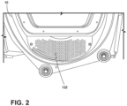
FIG. 2 is an enlarged partial perspective view of a front grille of the laundry appliance ofFIG. 1 ; -
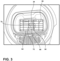
FIG. 3 is an enlarged partial perspective view of a foreign particulate collector of the present disclosure coupled to a door; -
FIG. 4 is a front elevational view of a laundry appliance with a foreign particulate collector of the present disclosure coupled to a door of the laundry appliance; -
FIG. 5 is a schematic view of a foreign particulate collector of the present disclosure including a plurality of layers; -
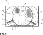
FIG. 6 is an enlarged partial perspective view of a drum with a foreign particulate collector of the present disclosure coupled to baffles in the drum; -
FIG. 7 is an enlarged partial perspective view of a drum with a foreign particulate collector of the present disclosure in the form of a consumable spray; -
FIG. 8 is an enlarged partial perspective view of a drum of a laundry appliance with a foreign particulate collector of the present disclosure with removable pads coupled to the drum; -
FIG. 9 is a front perspective view of a laundry appliance with a first foreign particulate collector and a second foreign particulate collector of the present disclosure; -
FIG. 10 is an enlarged partial perspective view of a foreign substrate collector of the present disclosure coupled to a front grille of a laundry appliance; -
FIG. 11 is an enlarged partial perspective view of a foreign substrate collector of the present disclosure coupled to a rear wall of a laundry appliance; -
FIG. 12 is an enlarged partial perspective view of a foreign substrate collector of the present disclosure disposed within a laundry cavity of a laundry appliance; -
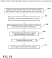
FIG. 13 is a linear flow diagram illustrating a method for collecting particulate during performance of a laundry cycle; and -
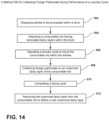
FIG. 14 is a linear flow diagram illustrating a method for collecting particulate during performance of a laundry cycle. - The components in the figures are not necessarily to scale, emphasis instead being placed upon illustrating the principles described herein.
- The present illustrated embodiments reside primarily in combinations of method steps and apparatus components related to a foreign particulate collector. Accordingly, the apparatus components and method steps have been represented, where appropriate, by conventional symbols in the drawings, showing only those specific details that are pertinent to understanding the embodiments of the present disclosure so as not to obscure the disclosure with details that will be readily apparent to those of ordinary skill in the art having the benefit of the description herein. Further, like numerals in the description and drawings represent like elements.
- For purposes of description herein, the terms "upper," "lower," "right," "left," "rear," "front," "vertical," "horizontal," and derivatives thereof shall relate to the disclosure as oriented in
FIG. 1 . Unless stated otherwise, the term "front" shall refer to the surface of the element closer to an intended viewer, and the term "rear" shall refer to the surface of the element further from the intended viewer. However, it is to be understood that the disclosure may assume various alternative orientations, except where expressly specified to the contrary. It is also to be understood that the specific devices and processes illustrated in the attached drawings, and described in the following specification are simply exemplary embodiments of the inventive concepts defined in the appended claims. Hence, specific dimensions and other physical characteristics relating to the embodiments disclosed herein are not to be considered as limiting, unless the claims expressly state otherwise. - The terms "including," "comprises," "comprising," or any other variation thereof, are intended to cover a non-exclusive inclusion, such that a process, method, article, or apparatus that comprises a list of elements does not include only those elements but may include other elements not expressly listed or inherent to such process, method, article, or apparatus. An element proceeded by "comprises a . . . " does not, without more constraints, preclude the existence of additional identical elements in the process, method, article, or apparatus that comprises the element.
- Referring to
FIGS. 1-12 ,reference numeral 10 generally designates a laundry appliance including acabinet 12 that defines anopening 14. Adoor 16 is operably coupled to thecabinet 12 proximate to the opening 14. Adrum 18 is disposed within thecabinet 12 and defines aprocessing space 20. Thedrum 18 also includesbaffles 22. Aforeign particulate collector 24 is operably coupled to and selectively removable from at least one of thedoor 16 and thedrum 18. Theforeign particulate collector 24 includes acollection material 26 configured to collectforeign particulates 28 within theprocessing space 20 defined by thedrum 18. - Referring to
FIGS. 1-3 , thelaundry appliance 10 is illustrated as a laundry dryer. It is also contemplated that thelaundry appliance 10 may be configured as any one of a washer, a dryer, and/or a combination washer and dryer. Thecabinet 12 is illustrated as having anouter shell 40, including afront panel 42 to which thedoor 16 is coupled, in which amachine compartment 44 is disposed. It is also contemplated that thecabinet 12 defines aslot 46 proximate to thedoor 16 and theopening 14 in which alint filter 48 may be selectively disposed. Thelint filter 48 may collectforeign particulates 28. As discussed in more detail below, theforeign particulate collector 24 may include a firstforeign particulate collector 50 and a secondforeign particulate collector 52. By way of example, not limitation, thelint filter 48 may be configured as the secondforeign particulate collector 52 in some configurations. - The
drum 18 includes thebaffles 22 operably coupled to sidewalls 54 of thedrum 18. Thedrum 18 is positioned within thecabinet 12 proximate to theopening 14. It is also contemplated that thedrum 18 is proximate to arear wall 56 of thelaundry appliance 10. Additionally or alternatively, therear wall 56 of thelaundry appliance 10 may be coupled to thedrum 18. As described further herein, theforeign particulate collector 24 may be coupled to or integrally formed with anyone of thedrum 18, therear wall 56, and/or thedoor 16 of thelaundry appliance 10. - Referring still to
FIGS. 1-3 , thedoor 16 is illustrated as being operably coupled to thefront panel 42 of thecabinet 12 proximate to theopening 14. Thedoor 16 may be configured as a flat panel, a fishbowl, and/or any other practicable door for use with thelaundry appliance 10. Thedoor 16 is configured to selectively conceal theopening 14 between an open position and a closed position. Stated differently, thedoor 16 may provide selective access to theprocessing space 20 via theopening 14. Thedoor 16 includes aperipheral rim 60 disposed around acentral body 62. Theperipheral rim 60 is selectively and operably coupled to thecabinet 12, and thecentral body 62 is selectively disposed within theopening 14 in the closed position of thedoor 16. It is generally contemplated that thecentral body 62 may be formed from a plastic transparent material and/or any other practicable material, such as metals, to construct thedoor 16. - With further reference to
FIGS. 1-3 , ahousing 64 is operably coupled to thecentral body 62 of thedoor 16. It is generally contemplated that thehousing 64 is configured to receive theforeign particulate collector 24, such that thehousing 64 defines acentral cavity 66 in which theforeign particulate collector 24 may be disposed. Thehousing 64 may be comprised of a heat resistant plastic and/or other heat resistant material generally practicable for use proximate to theprocessing space 20 during operation of the laundry cycle. As illustrated inFIG. 3 , theforeign particulate collector 24 includes acollection feature 68 that can be disposed within thehousing 64. - It is generally contemplated that the
collection feature 68 may be selectively removed from thehousing 64 and repositioned within thehousing 64 after a cleaning process of thecollection feature 68. By way of example, not limitation, thecollection feature 68 is configured to collect theforeign particulates 28 within theprocessing space 20. Thecollection feature 68 includes thecollection material 26 of theforeign particulate collector 24, which is configured to attract and retain theforeign particulates 28. It is generally contemplated that thecollection material 26 may be a sticky material, a tacky surface, abrasive fabric, and/or other collection materials practicable for removing and collecting theforeign particulates 28. The user may remove thecollection feature 68 from thehousing 64 to clean or otherwise remove theforeign particulates 28 from theforeign particulate collector 24 once thecollection feature 68 appears to be fully saturated withforeign particulates 28. As illustrated inFIG. 3 , thecollection feature 68 may have a circular shape with anindicia 70 that indicates that thecollection feature 68 is configured to collect theforeign particulates 28, such as pet hair. For example, theforeign particulate collector 24 illustrated inFIG. 3 includes a paw-print indicia 70 to indicate that pet hair may be collected by theforeign particulate collector 24. It is also contemplated that thecollection feature 68 may includeother indicia 70 to indicate various uses and may have any shape practicable for collecting theforeign particulates 28. - With further reference to
FIGS. 1-3 , theforeign particulates 28 can accumulate along thecollection material 26 of thecollection feature 68, such that theforeign particulates 28 are retained on thecollection feature 68 via thecollection material 26. Thecollection material 26 is contemplated to be compatible with water or other liquids to assist in the removal of theforeign particulates 28 from thecollection feature 68. In this manner, thecollection feature 68 is typically a cleanable member that can be reused for a plurality of laundry cycles. Thecollection material 26 of theforeign particulate collector 24 can configured to remain sticky or otherwise tacky after cleaning and removal of theforeign particulates 28 from thecollection feature 68. Additionally or alternatively, thecollection material 26 may be an abrasive fabric that may be cleaned of theforeign particulates 28 to be reused. In either configuration, thecollection feature 68 may be removed from thehousing 64 after theforeign particulates 28 have accumulated on thecollection material 26 to be cleaned, and subsequently disposed back into thehousing 64 for continued and repeated use. When wetted, thecollection feature 68 has diminished adhesive properties for cleaning. When dry, the collection feature 68 exhibits the adhesive features needed to collect theforeign particulates 28. - As illustrated in
FIGS. 2 and3 , thehousing 64 includes a plurality ofapertures 72 that receive theforeign particulates 28 from theprocessing space 20. Additionally or alternatively, thehousing 64 may include slots and/or other openings configured to receive theforeign particulates 28 from theprocessing space 20. A blower movesprocess air 74 through an airflow path that includes theprocessing space 20. Theprocess air 74 directs theforeign particulates 28 toward thehousing 64 during the laundry cycle. The flow ofprocess air 74 may assist in removing theforeign particulates 28 fromclothing items 76 to be collected by theforeign particulate collector 24. - Referring now to
FIGS. 1 and4-6 , theforeign particulate collector 24 includes a plurality oflayers 80 that are removably coupled to one another via thecollection material 26. Stated differently, theforeign particulate collector 24 includes a plurality ofremovable layers 80. It is contemplated that the plurality oflayers 80 may be disposed on thecentral body 62 of thedoor 16 proximate to theopening 14 defined by thecabinet 12. Eachlayer 80 includes thecollection material 26 of theforeign particulate collector 24, such that anoutermost layer 82 is configured to collect theforeign particulates 28 within theprocessing space 20. Each of the plurality oflayers 80 defines acontact surface 84 which intermittently contacts theclothing items 76. Theclothing items 76 tumble within theprocessing space 20 and may contact thecontact surface 84 of theforeign particulate collector 24. The contact between thecontact surface 84 and theclothing items 76 assists in releasing and removing theforeign particulates 28 from theclothing items 76. - Each
layer 80 has afirst side 86 and asecond side 88, and it is generally contemplated that thefirst side 86 includes thecollection material 26 of theforeign particulate collector 24. Thesecond side 88 may be laminated or otherwise coated. The coating of thesecond side 88 assists in selectively removing theoutermost layer 82 from thecollection material 26 of thefirst side 86 of anadjacent layer 90. Stated differently, thesecond side 88 of afirst layer 92 of theforeign particulate collector 24 is removably coupled with thefirst side 86 of asecond layer 94 of theforeign particulate collector 24. Thefirst layer 92 is configured with thecollection material 26 to selectively retain theadjacent layer 90. Eachlayer 80 is selectively removable to provide aclean layer 80 of thecollection material 26 to collect theforeign particulates 28 within theprocessing space 20. - Referring still to
FIGS. 1 and4-6 , it is generally contemplated that the plurality oflayers 80 of theforeign particulate collector 24 may be coupled to thedoor 16 via magnets, clips, snaps, adhesives, and/or other methods of coupling. The selective removal of each of the plurality oflayers 80 assists the user in removing theforeign particulates 28 from theprocessing space 20. The user can selectively remove the visible,outermost layer 82 of the plurality oflayers 80 when theforeign particulates 28 have accumulated on theoutermost layer 82. - While
FIG. 4 depicts the plurality oflayers 80 being coupled to thedoor 16, it is also contemplated that the plurality oflayers 80 may be operably coupled to thesidewalls 54 of thedrum 18 and/or thebaffles 22 of thedrum 18. For example,FIG. 6 depicts theforeign particulate collector 24 with the plurality oflayers 80 on thebaffles 22. Regardless of the placement of theforeign particulate collector 24, the plurality oflayers 80 selectively remove theforeign particulates 28 from theclothing items 76 during a laundry cycle. Stated differently, theforeign particulate collector 24 disposed on thebaffles 22 may include the plurality oflayers 80, such that eachlayer 80 may be selectively removed upon completion of the laundry cycle for removal of theforeign particulates 28. The position of theforeign particulate collector 24 on thebaffles 22 maximizes the contact with theclothing items 76 to assist in removing and collecting theforeign particulates 28. - With reference now to
FIGS. 7 and 8 , theforeign particulate collector 24 may be aconsumable spray 100. Thecollection material 26 may be integrated in theconsumable spray 100 as an adhesive. Theconsumable spray 100 provides anadhesive surface 102 that is applied to anapplication surface 104. By way of example, not limitation, theapplication surface 104 may be the sidewalls 54 of thedrum 18 and/or thecentral body 62 of thedoor 16. Theadhesive surface 102 is configured to capture theforeign particulates 28 within thedrum 18 on thecollection material 26. Theclothing items 76 contact theadhesive surface 102 during the laundry cycle, and theforeign particulates 28 may be trapped on theadhesive surface 102. It is generally contemplated that theadhesive surface 102 may be removed after the laundry cycle is complete. For example, theadhesive surface 102 may be peeled, wiped and/or vacuumed off of theapplication surface 104. Theadhesive surface 102 may subsequently be reapplied via theconsumable spray 100 for an upcoming laundry cycle. - Alternatively, the
consumable spray 100 may be disposed upon aremovable pad 110, such that theconsumable spray 100 can dispose theadhesive surface 102 on theremovable pad 110. Theremovable pad 110 may then be disposed on theapplication surface 104, such as within thedrum 18, to trap theforeign particulates 28. For example, theremovable pads 110 may be operably coupled to thesidewalls 54 of thedrum 18 via magnets, clips, snaps, adhesive, and/or other practicable coupling methods. It is also contemplated that theremovable pads 110 may be operably coupled to thebaffles 22 and/or the door 16 (FIG. 4 ) proximate to theopening 14 of thecabinet 12. - Referring now to
FIG. 8 , theremovable pad 110 is illustrated as theforeign particulate collector 24. Theremovable pad 110 may include thecollection material 26 integrally formed with acollection surface 112 on which theforeign particulates 28 may be collected. Thecollection material 26 is disposed along thecollection surface 112 of theremovable pad 110 to remove theforeign particulates 28 from theclothing items 76 within thedrum 18. It is also contemplated that theremovable pad 110 is configured to be washable as theremovable pad 110 is removably coupled to thelaundry appliance 10. For example, theremovable pad 110 may be removed from thedrum 18 once thecollection surface 112 is filled with theforeign particulates 28. Theremovable pad 110 may be washed via a separate laundry machine and/or by hand by the user. For example, the user may rinse the mat with a liquid to remove theforeign particulates 28 outside of thelaundry appliance 10. It is contemplated that theremovable pad 110 can be operably coupled to thesidewalls 54 of thedrum 18 via magnets and/or other coupling features to assist in the selective and operable removal from thesidewalls 54. - With reference to
FIGS. 9-11 , theforeign particulate collector 24 may include a plurality ofprojections 120 extending from thecollection material 26. As described herein, theforeign particulate collector 24 may be operably coupled to any one of thedrum 18, thedoor 16, thesidewalls 54 of thedrum 18, and/or therear wall 56 of thelaundry appliance 10. It is also contemplated that theforeign particulate collector 24 may be coupled to a grill or ventilation plate 122 (FIG. 2 ) of thelaundry appliance 10 proximate to the lint filter 48 (FIG. 1 ). - The
ventilation plate 122 defines an inner surface of thedoor 16 and is exposed to theprocessing space 20 when thedoor 16 is in a closed position. Thecollection feature 68 is positioned within thedoor 16, such as behind theventilation plate 122. In this manner, theventilation plate 122 defines a communication between the processingspace 20 and thecollection feature 68. Thehousing 64 can include an access panel that is operable to provide access to thecollection feature 68. In certain aspects of the device, theventilation plate 122 can operate as an access panel. It is also contemplated that theventilation plate 122 can include aslot 46 orother opening 14 that allows thecollection feature 68 to be inserted and removed from thedoor 16. As illustrated inFIG. 9 , the firstforeign particulate collector 50 may be operably coupled to thedoor 16, and the secondforeign particulate collector 52 may be operably coupled to therear wall 56 of thelaundry appliance 10. Additionally, as exemplified inFIG. 2 , theventilation plate 122 can be positioned below a viewing window of thedoor 16. - The
projections 120 outwardly extend from thecollection material 26 of each of the first and second foreignparticulate collectors clothing items 76 within theprocessing space 20. The gentle engagement of theprojections 120 assists in removal, and potentially capture, of theforeign particulates 28 from theclothing items 76. For example, theprojections 120 may be configured as spikes and/or rounded protrusions extending from thecollection material 26 to assist in releasing theforeign particulates 28 from theclothing items 76. Theforeign particulate collector 24 may include both spikedprojections 120 androunded projections 120 to provide avaried surface 124 along theforeign particulate collector 24. Thevaried surface 124 may further assist in the removal of theforeign particulates 28 from theclothing items 76. - With further reference to
FIGS. 9-11 , it is generally contemplated that theprojections 120 may be formed from a generally flexible material, such that theprojections 120 can gently engage theclothing items 76 within theprocessing space 20. Theprojections 120 may flex and bend to minimize potential abrasive contact with theclothing items 76. It is also contemplated that the process air 74 (FIG. 1 ) within theprocessing space 20 may assist in directing any remainingforeign particulates 28 toward either theforeign particulate collector 24 disposed on thedoor 16 and/or thelint filter 48 configured to collect any remainingforeign particulates 28. - In any one of these configurations, the
foreign particulate collector 24 is configured to be selectively removable from thelaundry appliance 10 to assist in cleaning and maintenance of the foreignparticulate collectors 24. It is also contemplated that the foreignparticulate collectors 24 illustrated inFIGS. 9-11 may include the plurality oflayers 80 described herein. It is generally contemplated that the plurality oflayers 80 may be configured as removable tacky layers or removable sticky layers with a dedicated set of theprojections 120, incorporated into eachlayer 80. Accordingly, thefirst side 86 includes both thecollection material 26 and theprojections 120. Eachlayer 80 may be selectively removed to reveal a new set ofprojections 120 andcollection material 26 along thefirst side 86 of thelayer 80. - With reference now to
FIG. 12 , theforeign particulate collector 24 may be alternately configured as aball 130, such as a consumable orb, having the plurality oflayers 80 and/or theprojections 120 that are layered around a central core. It is generally contemplated that theballs 130 are formed from thecollection material 26. Like the other configurations described herein, theballs 130 are configured to collect theforeign particulates 28 within theprocessing space 20 during a laundry cycle via gentle engagement with theclothing items 76. At least oneball 130 is disposed within theprocessing space 20 during the laundry cycle. Theball 130 rotates around thedrum 18 with theclothing items 76 to collect theforeign particulates 28. The rotation of theball 130 and theclothing items 76 within thedrum 18 maximizes the contact between theclothing items 76 and theball 130 to collect theforeign particulates 28. - For example, the
balls 130 may access portions of theclothing items 76 that may be set apart from thesidewalls 54 of thedrum 18, such that theballs 130 access a concealed portion of theclothing items 76 relative to thesidewalls 54 of thedrum 18. It is also contemplated that multiple configurations of theforeign particulate collector 24, as described herein may be utilized in various combinations. For example, theclothing items 76 may gently engage the firstforeign particulate collector 50 on thesidewalls 54 of thedrum 18 and the secondforeign particulate collector 52 configured as theball 130 within theprocessing space 20. The maximized contact between the multiple foreignparticulate collectors 24 assists in the maximal removal of theforeign particulates 28 from theclothing items 76. - Referring now to
FIGS 1-13 , having described various aspects of the device, amethod 400 is disclosed for collectingforeign particulates 28 during performance of a laundry cycle. Thismethod 400 includes astep 402 of applying an adhesive spray that forms anadhesive surface 102 on at least one of an inner surface of adoor 16 and aninterior surface 58 of arotating drum 18 for alaundry appliance 10 to form a tacky layer. Astep 404 includes disposing articles, such asclothing items 76, to be processed within thedrum 18. Step 406 includes operating a laundry cycle, wherein rotation of thedrum 18 directs theclothing items 76 against the tacky layer. Step 408 includes collectingforeign particulates 28 using the tacky layer. Step 410 includes completing the drying cycle. Step 412 includes removing the tacky layer from theappliance 10. This sprayed on tacky layer is configured to typically be used for a single drying cycle or a small number of drying cycles. After this use, the tacky layer can be peeled or otherwise removed from theappliance 10 for disposal. - Referring now to
FIGS 1-12 and14 , having described various aspects of the device, amethod 500 is a method for collectingforeign particulates 28 during performance of a laundry cycle of alaundry appliance 10. According to themethod 500,step 502 includes disposing articles, such asclothing items 76 to be processed within adrum 18. Step 504 includes disposing aconsumable orb 130 within thedrum 18. As described herein, theconsumable orb 130 includes a plurality of disposable tacky layers that can be peeled off as theconsumable orb 130 is used. Step 506 includes operating a laundry cycle, wherein rotation of thedrum 18 moves theconsumable orb 130 within the articles. Step 508 includes collectingforeign particulate 28, wherein engagement of the articles with an outermost tacky layer of the plurality of disposable tacky layers transfers the foreign particulate 28 from the articles to the outermost tacky layer. Step 510 includes completing a drying cycle. Step 512 of themethod 500 includes removing the outermost tacky layer from theconsumable orb 130 to define a new outermost tacky layer. - Referring again to
FIGS. 1-14 , theforeign particulate collector 24 advantageously assists in removingforeign particulates 28 from theclothing items 76 in thedrum 18. The selective removability of theforeign particulate collector 24 assists in maintaining a clean surface with which theclothing items 76 may engage. The inclusion of thecollection material 26 assists in grabbing and retaining theforeign particulates 28 to assist in removal from theclothing items 76. Theprojections 120 may further assist in gently agitating theclothing items 76 to release theforeign particulates 28. Overall, theforeign particulate collector 24 maximizes the removal offoreign particulates 28 from theclothing items 76 within theprocessing space 20, regardless of the configuration. - The invention disclosed herein is further summarized in the following paragraphs and is further characterized by combinations of any and all of the various aspects described therein.
- According to another aspect of the present disclosure, a laundry appliance includes a cabinet defining an opening. A drum is disposed within the cabinet and defines a processing space. A blower directs process air through an airflow path that includes the drum. A door is operably coupled to the cabinet. The door is operable to an open position that provides selective access through the opening and into the drum. A foreign particulate collector is operably coupled to the door. The foreign particulate collector includes a collection material configured to collect foreign particulates within the drum.
- According to another aspect, the foreign particulate collector includes a housing operably coupled to the door and a collection feature selectively disposed within the housing.
- According to yet another aspect, the door includes a central body and the housing is attached to the central body. The door, the housing and the drum define the processing space for treating clothing items.
- According to another aspect of the present disclosure, the foreign particulate collector includes the collection feature that is disposed within the housing. The drum and the blower operate to direct the process air through the housing and along the collection feature.
- According to another aspect, the collection feature includes a tacky surface.
- According to yet another aspect, the collection feature of the foreign particulate collector includes projections extending from the tacky surface.
- According to another aspect of the present disclosure, the housing includes a ventilation plate that defines an inner surface of the door that is exposed to the processing space in a closed position. The collection feature is positioned within the door and the ventilation plate provides communication between the drum and the collection feature.
- According to another aspect, the ventilation plate is positioned below a window disposed within the door.
- According to yet another aspect, the housing includes an access panel that is operable to remove the collection feature from the door.
- According to another aspect of the present disclosure, the collection feature is a cleanable member that can be removed from the housing for cleaning and replacement within the housing.
- According to another aspect, the foreign particulate collector is attached to an inner surface of the door. The foreign particulate collector defines a portion of the processing space when the door is in the closed position.
- According to yet another aspect, the foreign particulate collector includes one of a tacky surface and a plurality of projections.
- According to another aspect of the present disclosure, the foreign particulate collector includes the tacky surface, wherein the tacky surface is defined within a plurality of removable tacky layers.
- According to another aspect, each of the removable tacky layers includes a dedicated set of projections.
- According to yet another aspect, operation of the drum manipulates articles in the drum to engage at least a portion of the foreign particulate collector.
- According to another aspect of the present disclosure, a method for collecting particulate during performance of a laundry cycle of a laundry appliance includes applying a spray to at least one of an inner surface of a door and an interior surface of a rotating drum for a laundry appliance. The spray defines a tacky layer. Articles to be processed are disposed within the drum. A laundry cycle is operated, where rotation of the drum directs the articles against the tacky layer. Foreign particulate is collected, where engagement of the articles with the tacky layer transfers the foreign particulate from the articles to the tacky layer. The laundry cycle is completed. The tacky layer is removed from the appliance.
- According to another aspect, the spray is disposed on a removable pad that is selectively coupled to one of the door and the drum.
- According to yet another aspect, the removable pad is selectively attached to a baffle of the drum.
- According to another aspect of the present disclosure, a method for collecting particulate during performance of a laundry cycle of a laundry appliance includes disposing articles to be processed within a drum. A consumable orb is disposed within the drum, where the consumable orb includes a plurality of disposable tacky layers. A laundry cycle is operated, where rotation of the drum moves the consumable orb within the articles. Foreign particulate is collected, where engagement of the articles with an outermost tacky layer of the plurality of disposable tacky layers transfers the foreign particulate from the articles to the outermost tacky layer. A drying cycle is completed. The outermost tacky layer is removed from the consumable orb to define a new outermost tacky layer.
- According to another aspect, the orb includes a central core that is surrounded by the plurality of disposable tacky layers.
Claims (15)
- A laundry appliance (10) comprising:a cabinet (12) defining an opening (14);a drum (18) disposed within the cabinet (12) and defining a processing space (20);a blower that directs process air (74) through an airflow path that includes the drum (18);a door (16) operably coupled to the cabinet (12), wherein the door (16) is operable to an open position that provides selective access through the opening (14) and into the drum (18); anda foreign particulate collector (24) operably coupled to the door (16), the foreign particulate collector (24) including a collection material (26) configured to collect foreign particulates (28) within the drum (18).
- The laundry appliance (10) of claim 1, wherein the foreign particulate collector (24) includes a housing (64) operably coupled to the door (16) and a collection feature (68) selectively disposed within the housing (64).
- The laundry appliance (10) of claim 2, wherein the door (16) includes a central body (62) and wherein the housing (64) is attached to the central body (62), wherein the door (16), the housing (64) and the drum (18) define the processing space (20) for treating clothing items (76).
- The laundry appliance (10) of any one of claims 2-3, wherein the foreign particulate collector (24) includes the collection feature (68) that is disposed within the housing (64), wherein the drum (18) and the blower operate to direct the process air (74) through the housing (64) and along the collection feature (68).
- The laundry appliance (10) of claim 4, wherein the collection feature (68) includes a tacky surface.
- The laundry appliance (10) of claim 5, wherein the collection feature (68) of the foreign particulate collector (24) includes projections (120) extending from the tacky surface.
- The laundry appliance (10) of claim 6, wherein the housing (64) includes a ventilation plate (122) that defines an inner surface of the door (16) that is exposed to the processing space (20) in a closed position, wherein the collection feature (68) is positioned within the door (16) and the ventilation plate (122) provides communication between the drum (18) and the collection feature (68).
- The laundry appliance (10) of claim 7, wherein the ventilation plate (122) is positioned below a window disposed within the door (16).
- The laundry appliance (10) of any one of claims 2-8, wherein the housing (64) includes an access panel that is operable to remove the collection feature (68) from the door (16).
- The laundry appliance (10) of claim 9, wherein the collection feature (68) is a cleanable member that can be removed from the housing (64) for cleaning and replacement within the housing (64).
- The laundry appliance (10) of any one of claims 7-10, wherein the foreign particulate collector (24) is attached to an inner surface of the door (16), and wherein the foreign particulate collector (24) defines a portion of the processing space (20) when the door (16) is in the closed position.
- The laundry appliance (10) of claim 11, wherein the foreign particulate collector (24) includes one of a tacky surface and a plurality of projections (120).
- The laundry appliance (10) of claim 12, wherein the foreign particulate collector (24) includes the tacky surface, wherein the tacky surface is defined within a plurality of removable tacky layers.
- The laundry appliance (10) of claim 13, wherein each of the removable tacky layers includes a dedicated set of projections (120).
- The laundry appliance (10) of any one of claims 11-14, wherein operation of the drum (18) manipulates articles in the drum (18) to engage at least a portion of the foreign particulate collector (24).
Applications Claiming Priority (2)
| Application Number | Priority Date | Filing Date | Title |
|---|---|---|---|
| US202163232260P | 2021-08-12 | 2021-08-12 | |
| US17/859,298 US12442125B2 (en) | 2021-08-12 | 2022-07-07 | Foreign particulate collector for a laundry appliance |
Publications (1)
| Publication Number | Publication Date |
|---|---|
| EP4134480A1 true EP4134480A1 (en) | 2023-02-15 |
Family
ID=82786902
Family Applications (1)
| Application Number | Title | Priority Date | Filing Date |
|---|---|---|---|
| EP22188410.9A Withdrawn EP4134480A1 (en) | 2021-08-12 | 2022-08-02 | Foreign particulate collector for a laundry appliance |
Country Status (3)
| Country | Link |
|---|---|
| US (1) | US12442125B2 (en) |
| EP (1) | EP4134480A1 (en) |
| CN (1) | CN115710812A (en) |
Families Citing this family (1)
| Publication number | Priority date | Publication date | Assignee | Title |
|---|---|---|---|---|
| US12577716B2 (en) * | 2022-05-27 | 2026-03-17 | Samsung Electronics Co., Ltd. | Desiccant-based laundry device |
Citations (5)
| Publication number | Priority date | Publication date | Assignee | Title |
|---|---|---|---|---|
| DE8224528U1 (en) * | 1982-08-31 | 1983-02-03 | Licentia Patent-Verwaltungs-Gmbh, 6000 Frankfurt | ELECTRIC LAUNDRY DRYER |
| US4920662A (en) * | 1988-10-11 | 1990-05-01 | Seeburger James W | Lint remover for tumble-dryer |
| JPH09290097A (en) * | 1996-04-26 | 1997-11-11 | Nishida Kk | Waste remover for dryer |
| US20170055807A1 (en) * | 2015-08-31 | 2017-03-02 | Bradley M. C. Rucki | Devices and Methods for Adhesive-Based Removal of Pet Hair, Lint or Other Debris Using a Tumble Dryer |
| CN114575120A (en) * | 2022-03-01 | 2022-06-03 | 珠海格力电器股份有限公司 | Hair removing assembly, clothes treating equipment and clothes treating method |
Family Cites Families (20)
| Publication number | Priority date | Publication date | Assignee | Title |
|---|---|---|---|---|
| US2780009A (en) * | 1953-09-25 | 1957-02-05 | Gen Motors Corp | Domestic appliance |
| US5210960A (en) * | 1992-09-14 | 1993-05-18 | Larue Len | Lint filter |
| US6576323B2 (en) | 1998-03-11 | 2003-06-10 | Procter & Gamble | Fabric cleaning article with texturing and/or a tackiness agent |
| US7441345B2 (en) | 2005-06-07 | 2008-10-28 | Ken Taylor | Laundering aid removing adherent matter from fabric articles |
| DE102005035652A1 (en) * | 2005-07-29 | 2007-02-01 | BSH Bosch und Siemens Hausgeräte GmbH | Heat exchanger device for a tumble dryer |
| KR101443605B1 (en) * | 2007-04-05 | 2014-09-23 | 엘지전자 주식회사 | operating method for drum type laundry machine |
| BR112012028154B8 (en) * | 2010-05-04 | 2022-06-07 | Lg Electronics Inc | Method of controlling equipment for treating clothes |
| KR20120082968A (en) * | 2011-01-16 | 2012-07-25 | 삼성전자주식회사 | Washing machine and pulsator thereof |
| DE102013008483A1 (en) | 2013-05-10 | 2014-11-27 | Stefan Melzner | Hair and lint wiper with rubber surface and Bschwerung as an addition to the tumble dryer, especially for the removal of animal hair from fabric surfaces |
| KR102460252B1 (en) * | 2015-07-17 | 2022-10-27 | 엘지전자 주식회사 | Fabric dryer |
| KR102627696B1 (en) * | 2016-07-22 | 2024-01-23 | 삼성전자주식회사 | Clothes dryer |
| US10531784B2 (en) | 2016-11-21 | 2020-01-14 | Michael Sweigart | Device and method for removing fur and hair from fabrics |
| US10280551B2 (en) | 2016-11-21 | 2019-05-07 | Michael Sweigart | Device and method for removing fur and hair from fabrics |
| US10100459B2 (en) * | 2017-01-06 | 2018-10-16 | Whirlpool Corporation | Flexible drying solution for delivering clothing care externally of a drying appliance |
| WO2019199269A1 (en) | 2018-04-09 | 2019-10-17 | Kramer Carol | Laundering aid systems for removing matter from objects |
| US10765974B2 (en) * | 2019-01-25 | 2020-09-08 | Haier Us Appliance Solutions, Inc. | Lint collection assembly for a dryer appliance |
| KR20200096049A (en) * | 2019-02-01 | 2020-08-11 | 엘지전자 주식회사 | Laundry treating apparatus |
| US10941513B2 (en) * | 2019-04-23 | 2021-03-09 | Haier Us Appliance Solutions, Inc. | Hinged housing for a lint trap of a dryer appliance |
| US12139843B2 (en) * | 2021-01-12 | 2024-11-12 | Whirlpool Corporation | Foreign substrate collector for a laundry appliance |
| WO2022169322A1 (en) * | 2021-02-08 | 2022-08-11 | Lg Electronics Inc. | Laundry treating apparatus |
-
2022
- 2022-07-07 US US17/859,298 patent/US12442125B2/en active Active
- 2022-08-02 EP EP22188410.9A patent/EP4134480A1/en not_active Withdrawn
- 2022-08-11 CN CN202210964187.1A patent/CN115710812A/en active Pending
Patent Citations (5)
| Publication number | Priority date | Publication date | Assignee | Title |
|---|---|---|---|---|
| DE8224528U1 (en) * | 1982-08-31 | 1983-02-03 | Licentia Patent-Verwaltungs-Gmbh, 6000 Frankfurt | ELECTRIC LAUNDRY DRYER |
| US4920662A (en) * | 1988-10-11 | 1990-05-01 | Seeburger James W | Lint remover for tumble-dryer |
| JPH09290097A (en) * | 1996-04-26 | 1997-11-11 | Nishida Kk | Waste remover for dryer |
| US20170055807A1 (en) * | 2015-08-31 | 2017-03-02 | Bradley M. C. Rucki | Devices and Methods for Adhesive-Based Removal of Pet Hair, Lint or Other Debris Using a Tumble Dryer |
| CN114575120A (en) * | 2022-03-01 | 2022-06-03 | 珠海格力电器股份有限公司 | Hair removing assembly, clothes treating equipment and clothes treating method |
Also Published As
| Publication number | Publication date |
|---|---|
| US20230046936A1 (en) | 2023-02-16 |
| US12442125B2 (en) | 2025-10-14 |
| CN115710812A (en) | 2023-02-24 |
Similar Documents
| Publication | Publication Date | Title |
|---|---|---|
| EP2376702B1 (en) | Dryer and foreign material removing apparatus thereof | |
| EP2366044B1 (en) | Dryer | |
| JP4245653B1 (en) | Dryer | |
| US20100146812A1 (en) | Dryer and method of removing foreign substance in dryer | |
| US20080235978A1 (en) | Self-cleaning lint collector | |
| EP4026939A1 (en) | Foreign substrate collector for a laundry appliance | |
| JPS59214494A (en) | Drum type clothing dryer | |
| US12442125B2 (en) | Foreign particulate collector for a laundry appliance | |
| WO2008026724A1 (en) | Air conditioner | |
| JP6373020B2 (en) | Dryer | |
| CN115945002B (en) | Self-cleaning filter device and clothes dryer having the same | |
| EP4137633A1 (en) | Foreign particulate collector for a laundry appliance | |
| KR100959525B1 (en) | Foreign body collecting device of clothes dryer | |
| JP3259474B2 (en) | Clothes dryer lint collecting device | |
| TWI275678B (en) | Laundry washer/dryer | |
| JP3262656B2 (en) | Clothes dryer | |
| KR101685977B1 (en) | drying device | |
| KR101177479B1 (en) | drying device | |
| JP2011245099A (en) | Vacuum cleaner | |
| JP2744079B2 (en) | Clothes dryer | |
| JPH07204398A (en) | Device for collecting lint of clothes dryer | |
| JP4367244B2 (en) | Washing and drying machine | |
| JP2006000172A (en) | Washing and drying machine | |
| JPH0326299A (en) | clothes dryer | |
| JP3260359B2 (en) | Filter equipment such as dryers |
Legal Events
| Date | Code | Title | Description |
|---|---|---|---|
| PUAI | Public reference made under article 153(3) epc to a published international application that has entered the european phase |
Free format text: ORIGINAL CODE: 0009012 |
|
| STAA | Information on the status of an ep patent application or granted ep patent |
Free format text: STATUS: THE APPLICATION HAS BEEN PUBLISHED |
|
| AK | Designated contracting states |
Kind code of ref document: A1 Designated state(s): AL AT BE BG CH CY CZ DE DK EE ES FI FR GB GR HR HU IE IS IT LI LT LU LV MC MK MT NL NO PL PT RO RS SE SI SK SM TR |
|
| RAP3 | Party data changed (applicant data changed or rights of an application transferred) |
Owner name: WHIRLPOOL CORPORATION |
|
| STAA | Information on the status of an ep patent application or granted ep patent |
Free format text: STATUS: REQUEST FOR EXAMINATION WAS MADE |
|
| 17P | Request for examination filed |
Effective date: 20230814 |
|
| RBV | Designated contracting states (corrected) |
Designated state(s): AL AT BE BG CH CY CZ DE DK EE ES FI FR GB GR HR HU IE IS IT LI LT LU LV MC MK MT NL NO PL PT RO RS SE SI SK SM TR |
|
| P01 | Opt-out of the competence of the unified patent court (upc) registered |
Effective date: 20230821 |
|
| STAA | Information on the status of an ep patent application or granted ep patent |
Free format text: STATUS: THE APPLICATION HAS BEEN WITHDRAWN |
|
| 18W | Application withdrawn |
Effective date: 20240625 |