EP4134299A1 - Fuel dams, aircraft wing boxes, aircraft, and methods of assembling aircraft wings - Google Patents
Fuel dams, aircraft wing boxes, aircraft, and methods of assembling aircraft wings Download PDFInfo
- Publication number
- EP4134299A1 EP4134299A1 EP22186542.1A EP22186542A EP4134299A1 EP 4134299 A1 EP4134299 A1 EP 4134299A1 EP 22186542 A EP22186542 A EP 22186542A EP 4134299 A1 EP4134299 A1 EP 4134299A1
- Authority
- EP
- European Patent Office
- Prior art keywords
- fuel
- dams
- rib
- stringers
- ribs
- Prior art date
- Legal status (The legal status is an assumption and is not a legal conclusion. Google has not performed a legal analysis and makes no representation as to the accuracy of the status listed.)
- Granted
Links
Images



Classifications
-
- B—PERFORMING OPERATIONS; TRANSPORTING
- B64—AIRCRAFT; AVIATION; COSMONAUTICS
- B64D—EQUIPMENT FOR FITTING IN OR TO AIRCRAFT; FLIGHT SUITS; PARACHUTES; ARRANGEMENT OR MOUNTING OF POWER PLANTS OR PROPULSION TRANSMISSIONS IN AIRCRAFT
- B64D37/00—Arrangements in connection with fuel supply for power plant
- B64D37/02—Tanks
- B64D37/06—Constructional adaptations thereof
- B64D37/08—Internal partitioning
-
- B—PERFORMING OPERATIONS; TRANSPORTING
- B64—AIRCRAFT; AVIATION; COSMONAUTICS
- B64C—AEROPLANES; HELICOPTERS
- B64C3/00—Wings
- B64C3/18—Spars; Ribs; Stringers
-
- B—PERFORMING OPERATIONS; TRANSPORTING
- B64—AIRCRAFT; AVIATION; COSMONAUTICS
- B64C—AEROPLANES; HELICOPTERS
- B64C3/00—Wings
- B64C3/18—Spars; Ribs; Stringers
- B64C3/182—Stringers, longerons
-
- B—PERFORMING OPERATIONS; TRANSPORTING
- B64—AIRCRAFT; AVIATION; COSMONAUTICS
- B64C—AEROPLANES; HELICOPTERS
- B64C3/00—Wings
- B64C3/18—Spars; Ribs; Stringers
- B64C3/185—Spars
-
- B—PERFORMING OPERATIONS; TRANSPORTING
- B64—AIRCRAFT; AVIATION; COSMONAUTICS
- B64C—AEROPLANES; HELICOPTERS
- B64C3/00—Wings
- B64C3/18—Spars; Ribs; Stringers
- B64C3/187—Ribs
-
- B—PERFORMING OPERATIONS; TRANSPORTING
- B64—AIRCRAFT; AVIATION; COSMONAUTICS
- B64C—AEROPLANES; HELICOPTERS
- B64C3/00—Wings
- B64C3/34—Tanks constructed integrally with wings, e.g. for fuel or water
-
- B—PERFORMING OPERATIONS; TRANSPORTING
- B64—AIRCRAFT; AVIATION; COSMONAUTICS
- B64F—GROUND OR AIRCRAFT-CARRIER-DECK INSTALLATIONS SPECIALLY ADAPTED FOR USE IN CONNECTION WITH AIRCRAFT; DESIGNING, MANUFACTURING, ASSEMBLING, CLEANING, MAINTAINING OR REPAIRING AIRCRAFT, NOT OTHERWISE PROVIDED FOR; HANDLING, TRANSPORTING, TESTING OR INSPECTING AIRCRAFT COMPONENTS, NOT OTHERWISE PROVIDED FOR
- B64F5/00—Designing, manufacturing, assembling, cleaning, maintaining or repairing aircraft, not otherwise provided for; Handling, transporting, testing or inspecting aircraft components, not otherwise provided for
Definitions
- the present disclosure relates to fuel dams of aircraft wings.
- Typical wing construction includes front and rear spars, ribs that are spaced apart and extend between the spars, stringers that are spaced apart and extend transverse to the ribs, and skins that are coupled to the stringers.
- fuel dams may be used at interfaces between the stringers and tank end ribs to prevent fuel from passing through the interfaces and at interfaces between the stringers and fuel control ribs to restrict fuel from passing through the interfaces.
- installation of the fuel dams is performed after the wing box is already constructed, requiring technicians to enter the confined space of the wing box and making the installation difficult and time consuming.
- Fuel dams, aircraft wing boxes, aircraft, and methods of assembling aircraft wings are disclosed.
- Fuel dams comprise a fuel-dam body that defines a channel that is shaped to receive a portion of a stringer of the aircraft wing.
- the fuel-dam body comprises a stringer adherent surface, a rib adherent surface, and a pair of spaced-apart flanges.
- the stringer adherent surface defines the channel and is shaped to be adhered to the portion of the stringer of the aircraft wing.
- the rib adherent surface is shaped to be adhered to a rib of the aircraft wing within a notch of the rib.
- the spaced-apart flanges extend from the rib adherent surface and are positioned to project from the rib adherent surface on opposing sides of the notch of the rib.
- Aircraft wing boxes comprise spars, ribs, stringers, and fuel dams.
- the ribs extend between the spars and comprise notches.
- the stringers extend transverse to the ribs and are positioned partially within the notches.
- the fuel dams are positioned at interfaces between the stringers and the notches of at least a subset of the ribs.
- Aircraft comprise a fuselage and wings supported by the fuselage, with each wing comprising an aircraft wing box.
- Methods of assembling aircraft wings comprise adhering fuel dams to stringers and adhering the fuel dams to ribs.
- Aircraft 10, aircraft wing boxes 36 thereof, and methods 200 of assembling aircraft wings 12 are disclosed herein.
- aircraft 10 comprise at least a fuselage 11 and wings 12 that are supported by the fuselage 11.
- Each wing 12 comprises an aircraft wing box 36.
- aircraft wing boxes 36 typically comprise front and rear spars 14, ribs 16 that are spaced apart and extend between the spars 14, and stringers 18 that are spaced apart and extend transverse to the ribs 16.
- the ribs 16 comprise notches 22, and the stringers 18 are positioned partially within the notches 22 of the ribs 16.
- Notches 22 additionally or alternatively may be described as mouseholes in the aerospace industry. As shown in Fig.
- aircraft wing boxes 36 also typically comprise fuel dams 100 that are positioned at least a subset of interfaces 34 between the stringers 18 and the notches 22 of the ribs 16, such as at fuel flow control ribs and/or tank end ribs.
- the fuel dams 100 effectively seal the interfaces 34 to prevent or restrict fuel passing through the interfaces 34 at fuel tank boundaries or fuel tank baffles.
- T-stringers 24 comprise a base 26 and a blade 28 extending from the base 26.
- I-stringers, J-stringers, and Z-stringers may be described as comprising a base 26.
- the base 26 is coupled to a skin 20 of the aircraft wing 12.
- Hat stringers 30 typically comprise two base flanges 32 and a hat portion 35 extending away from and between the base flanges 32.
- the base flanges 32 are coupled to a skin 20 of the aircraft wing 12.
- Figs. 3-11 Examples of fuel dams 100 are illustrated in Figs. 3-11 .
- Fig. 3 illustrates a portion of an example wing box and shows example fuel dams 100 having two different configurations, specifically an example fuel dam for use with T-stringers, indicated at 102, and an example fuel dam for use with hat stringers, indicated at 120.
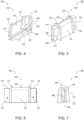
- Figs. 4-7 illustrate several views of example fuel dam 102 for use with T-stringers 24, and
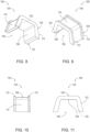
- Figs. 8-11 illustrate several views of example fuel dam 120 for use with hat stringers 30.
- the examples shown in Figs. 3-11 are non-exclusive and do not limit fuel dams 100 to the illustrated examples.
- fuel dams 100 each comprise a fuel-dam body 104 that defines a channel 106 that is shaped to receive a portion of a stringer 18, such as to fit over a cross-section of a stringer 18.
- the two examples of the fuel dams 100 that are illustrated in Figs. 3-11 differ mainly in terms of the configuration of the fuel-dam body 104 and the channel 106, which are respectively shaped to accommodate a different type of stringer, with fuel dam 102 configured to accommodate a T-stringer, and fuel dam 120 shaped to accommodate a hat stringer.
- the fuel-dam body 104 comprises a stringer adherent surface 108, a rib adherent surface 110, and a pair of spaced-apart flanges 112.
- the stringer adherent surface 108 defines the channel 106 and is shaped to be adhered to the portion of the stringer 18 received within the channel 106.
- the rib adherent surface 110 is shaped to be adhered to a rib 16 within a notch 22 of the rib 16.
- the spaced-apart flanges 112 extend from the rib adherent surface 110 and are positioned to project from the rib adherent surface 110 on opposing sides of the notch 22 within which the stringer 18 is positioned.
- the spaced-apart flanges 112 serve to contain any excess adhesive, or sealant, that is squeezed out from between the rib adherent surface 110 and the notch 22 of the rib 16 within which the fuel dam 100 is installed. Indeed, in some examples, the containment of any excess adhesive by the spaced-apart flanges 112 may result in the excess adhesive not needing to be removed following installation of a fuel dam 100, resulting in an efficient installation process.
- the spaced-apart flanges 112 are generally parallel to each other. In some examples, the spaced-apart flanges 112 extend generally perpendicular from the rib adherent surface 110. As used herein "generally parallel” and “generally perpendicular” means within 10 degrees of parallel and perpendicular, respectively.
- the specific orientation of the spaced-apart flanges 112 relative to the remainder of the fuel-dam body 104 of a specific fuel dam 100 may be based on corresponding shapes, dimensions, and configurations of the corresponding rib 16 and notch 22, adjacent which the spaced-apart flanges 112 will be positioned when the fuel dam 100 is operatively installed.
- a fuel dam 100 is monolithic or unitary in structure, that is, in its final manufactured form, it is constructed from a single unitary piece of material, as opposed to an assembly of discrete components that are coupled together via fasteners and/or adhesives.
- a fuel dam 100 may be additively manufactured or molded from a feedstock to form a monolithic body.
- a fuel dam 100 may be machined from a piece of material to form a monolithic body.
- a fuel dam 100 first may be molded or additively manufactured and subsequently machined to refine the final surfaces of the fuel dam 100.
- Fuel dams 100 may be constructed from any suitable material depending on the aircraft 10, such that the fuel dams 100 are compatible with aircraft fuel.
- fuel dams 100 may be constructed from a metal, a plastic material, or a fiber-reinforced plastic material.
- the spars 14, the ribs 16, the stringers 18, and the skins 20 of an aircraft wing 12 may be constructed from various materials, including metals, plastics, and fiber-reinforced plastics, depending on the construction of an aircraft 10.
- fuel dams 100 may be constructed from a nylon material that is selected to be compliant with electromagnetic emission specifications of aircrafts.
- the fuel-dam body 104 comprises end regions 114 that extend beyond the spaced-apart flanges 112 and that partially define the channel 106 and the stringer adherent surface 108. When present, such end regions 114 provide a greater surface area for stringer adherent surface 108 to be adhered and coupled to a corresponding stringer 18. In some such examples, the end regions 114 comprise fastener holes 116 for operatively fastening the fuel dam 100 to a corresponding stringer 18. Some such examples of fuel dams 100 may be configured as non-hat fuel dams. Some fuel dams 100 according to the present disclosure are free of fastener holes and exclusively rely on an adhesive for being adhered and coupled to a corresponding stringer 18 and a corresponding rib 16.
- fuel dams 100 may include one or more holes 122 extending through the fuel-dam body 104.
- the fuel dams 100 may be used at fuel tank baffles where fuel and/or water is permitted to flow, or drain, from one side of a corresponding rib 16 to the other.
- Fig. 12 methods 200 of assembling aircraft wings 12 are schematically presented.
- some steps are illustrated in dashed boxes indicating that such steps may be optional or may correspond to an optional version of a method 200. That said, not all methods according to the present disclosure are required to include the steps illustrated in solid boxes.
- the methods and steps illustrated in Fig. 12 are not limiting and other methods and steps are within the scope of the present disclosure, including methods having greater than or fewer than the number of steps illustrated, as understood from the discussions herein.
- the order of steps illustrated in Fig. 12 is not limiting, and the steps of methods 200 may be performed in any suitable order.
- methods 200 comprise adhering 202 fuel dams 100 to stringers 18, and adhering 204 the fuel dams 100 to at least a subset of ribs 16.
- adhering 202 the fuel dams 100 to the stringers 18 is performed prior to adhering 204 the fuel dams 100 to the ribs 16.
- the stringers 18 already may be coupled to a corresponding skin 20 when the fuel dams 100 are coupled to the stringers 18 or the fuel dams 100 may be adhered to the stringers 18 and then the combined stringers 18 and fuel dams 100 may be coupled to the corresponding skin 20.
- the assembly of the skin 20, the stringers 18, and the fuel dams 100 may be coupled to the ribs 16, including adhering 204 the fuel dams 100 to the ribs 16.
- Such implementations of methods 200 provide for the operative placement of the fuel dams 100 on the stringers 18 in an open environment, spaced-away from the remainder of the wing 12 or wing box 36 being assembled, enabling more ergonomic assembling of wings 12 than traditional wing assembly methods.
- not all methods 200 require the adhering of step 202 to be performed prior to the adhering step 204, and in other examples of methods 200, the adhering of step 204 is performed prior to the adhering of step 202.
- the adhering of step 202 and the adhering of step 204 may utilize any adhesive suitable for the materials of the ribs 16, the stringers 18, and the fuel dams 100, and the corresponding required strength and other specifications of an aircraft wing 12, as well as being compatible with aircraft fuel.
- Example adhesives include two-part, manganese dioxide cured polysulfide compounds and vulcanizing silicone rubber adhesives. Adhesives additionally or alternatively may be referred to as sealants.
- the adhering of step 202 comprises adhering 206 the fuel dams 100 to the stringers 18 in predetermined locations along the stringers 18.
- Some such methods 200 may further comprise indexing 228 the fuel dams 100 relative to the stringers 18 to determine the predetermined locations. Proper positioning of the fuel dams 100 on the stringers 18 results in the fuel dams 100 being spaced apart from each other at the correct spacing in relation to the ribs 16.
- step 204 the adhering of step 204 comprises positioning 208 the fuel dams 100 within respective notches 22 of the ribs 16.
- Some methods 200 further comprise coupling 210 the stringers 18 to a skin 20.
- the coupling of step 210 is performed prior to the adhering of step 202.
- such an order of assembly provides for the operative placement of the fuel dams 100 on the stringers 18 in an open environment, spaced-away from the remainder of the wing 12 or wing box 36 being assembled and resulting in more ergonomic assembling of wings 12 than traditional wing assembly methods.
- some methods 200 further comprise, prior to the adhering of step 202, acquiring 212 surface contour data of the stringers 18 and/or acquiring 214 surface contour data of the ribs 16, and then based on the surface contour data of the stringers 18 and/or the surface contour data of the ribs 16, refining 216 computer models of the fuel dams 100.
- coupling 210 is performed prior to the acquiring 212.
- the surface contour data may be acquired from detailed reviews of tolerance allocations and/or by reviewing previous fabrication data to establish statistical bounds of the fuel dams.
- the surface contour data may be acquired by various three-dimensional (3D) scanning techniques, such as time-of-flight laser scanning, triangulation based laser scanning, structured light 3D scanning, modulated light 3D scanning, passive stereoscopic 3D imaging, photogrammetric non-contact passive methods, etc.
- the computer models may be computer-aided design (CAD) and/or computer-aided manufacturing (CAM) models or files, which generally may be described as 3D models.
- step 212 The acquiring of step 212, the acquiring of step 214, and/or the refining of step 216 of such methods 200 may be described as being computer-implemented steps of methods 200. Accordingly, such steps of methods 200 may be performed by or controlled by a controller, that is, any suitable device or devices that are configured to perform the recited functions of the acquiring of step 212, the acquiring of step 214, and/or the refining of step 216.
- the controller may include one or more of an electronic controller, a dedicated controller, a special-purpose controller, a personal computer, a special-purpose computer, a display device, a logic device, a memory device, and/or a memory device having computer readable media suitable for storing computer-executable instructions for implementing aspects of systems and/or methods according to the present disclosure.
- one or more controllers may include, or be configured to read, non-transitory computer readable storage, or memory, media suitable for storing computer-executable instructions, or software, for implementing the acquiring of step 212, the acquiring of step 214, and/or the refining of step 216. Examples of such media include CD-ROMs, disks, hard drives, flash memory, etc.
- storage, or memory, devices and media having computer-executable instructions as well as computer-implemented methods and steps according to the present disclosure are considered to be within the scope of subject matter deemed patentable in accordance with Section 101 of Title 35 of the United States Code.
- a default computer model of a fuel dam 100 may be based on typical final dimensions of fuel dams 100 or based on the largest typical fuel dam 100 for a particular aircraft 10.
- the refining of step 216 manipulates the default computer model based on the acquired surface contour data of the stringers 18 and/or the ribs 16 to arrive at an updated computer model that has the desired dimensions of a specific fuel dam 100 based on a specific interface 34 between a specific stringer 18 and a specific rib 16 and based on desired tolerances.
- the refining of step 216 comprises defining 218 the stringer adherent surfaces 108 and/or the rib adherent surfaces 110 of the computer models of the fuel dams 100.
- the default computer model has corresponding adherent surfaces, but the modeling of one or both of these surfaces is refined based on the acquired surface contour data of a specific stringer 18 and/or a specific rib 16 with which a specific fuel dam 100 will be installed at the corresponding interface 34 thereof.
- the defining of step 218 comprises defining 220 spatial relationships between the stringer adherent surfaces 108 and the rib adherent surfaces 110 of the computer model for a particular fuel dam 100.
- some such methods 200 further comprise, following the refining of step 216, manufacturing 222 the fuel dams 100 based on the computer models. That is, custom fuel dams 100 are manufactured based on the surface contour data of the stringers 18 and/or the ribs 16 so that the fuel dams 100 meet appropriate dimensional tolerances of the actual aircraft wing box 36 being assembled.
- manufacturing 222 comprises additively manufacturing the fuel dams 100 based on the computer models. In some methods 200, manufacturing 222 comprises subtractively machining the fuel dams 100 based on the computer models. In some such methods 200, the additive manufacturing process may result in a final part with the desired dimensions. In other examples, a machining step may be performed following the additive manufacturing step to arrive at the final design dimensions of a fuel dam 100.
- the positioning of step 208 comprises positioning 224 the pair of spaced-apart flanges 112 of each fuel-dam body 104 on opposing sides of the notch 22 of the respective rib 16.
- adhering 204 the fuel dams 100 to the ribs 16 comprises containing 226 adhesive squeezeout between the pair of spaced-apart flanges 112 and the respective rib 16. That is, as discussed, the spaced-apart flanges 112 may serve to contain any excess adhesive that is squeezed out from between the rib adherent surface 110 of a fuel dam 100 and a notch 22 of the rib 16 within which the fuel dam 100 is being installed. In fact, in some examples, the excess adhesive contained by the spaced-apart flanges 112 may not need to be removed following installation of a fuel dam 100, resulting in an efficient installation process. In particular, in some methods 200, the adhering of step 202 and/or the adhering of step 204 does not require removal or cleaning of excess adhesive.
- methods 200 in which a fuel dam 100 comprises end regions 114 and fastener holes 116 extending therethough, such methods 200 also may comprise fastening 230 the fuel dams 100 to the stringers 18 with fasteners extending through the fastener holes 116 as schematically indicated in Fig. 12 . In other methods 200, no fasteners are used to couple the fuel dams 100 to the stringers 18 and/or to the ribs 16.
- the terms “adapted” and “configured” mean that the element, component, or other subject matter is designed and/or intended to perform a given function. Thus, the use of the terms “adapted” and “configured” should not be construed to mean that a given element, component, or other subject matter is simply “capable of” performing a given function but that the element, component, and/or other subject matter is specifically selected, created, implemented, utilized, programmed, and/or designed for the purpose of performing the function. It is also within the scope of the present disclosure that elements, components, and/or other recited subject matter that is recited as being adapted to perform a particular function may additionally or alternatively be described as being configured to perform that function, and vice versa. Similarly, subject matter that is recited as being configured to perform a particular function may additionally or alternatively be described as being operative to perform that function.
- the term "and/or" placed between a first entity and a second entity means one of (1) the first entity, (2) the second entity, and (3) the first entity and the second entity.
- Multiple entries listed with “and/or” should be construed in the same manner, i.e., "one or more" of the entities so conjoined.
- Other entities optionally may be present other than the entities specifically identified by the "and/or” clause, whether related or unrelated to those entities specifically identified.
- a reference to "A and/or B,” when used in conjunction with open-ended language such as “comprising,” may refer, in one example, to A only (optionally including entities other than B); in another example, to B only (optionally including entities other than A); in yet another example, to both A and B (optionally including other entities).
- These entities may refer to elements, actions, structures, steps, operations, values, and the like.
Landscapes
- Engineering & Computer Science (AREA)
- Aviation & Aerospace Engineering (AREA)
- Mechanical Engineering (AREA)
- Manufacturing & Machinery (AREA)
- Transportation (AREA)
- Standing Axle, Rod, Or Tube Structures Coupled By Welding, Adhesion, Or Deposition (AREA)
Abstract
Description
- The present disclosure relates to fuel dams of aircraft wings.
- Typical wing construction includes front and rear spars, ribs that are spaced apart and extend between the spars, stringers that are spaced apart and extend transverse to the ribs, and skins that are coupled to the stringers. When wings are used as fuel tanks, fuel dams may be used at interfaces between the stringers and tank end ribs to prevent fuel from passing through the interfaces and at interfaces between the stringers and fuel control ribs to restrict fuel from passing through the interfaces. Traditionally, installation of the fuel dams is performed after the wing box is already constructed, requiring technicians to enter the confined space of the wing box and making the installation difficult and time consuming.
- Fuel dams, aircraft wing boxes, aircraft, and methods of assembling aircraft wings are disclosed.
- Fuel dams comprise a fuel-dam body that defines a channel that is shaped to receive a portion of a stringer of the aircraft wing. The fuel-dam body comprises a stringer adherent surface, a rib adherent surface, and a pair of spaced-apart flanges. The stringer adherent surface defines the channel and is shaped to be adhered to the portion of the stringer of the aircraft wing. The rib adherent surface is shaped to be adhered to a rib of the aircraft wing within a notch of the rib. The spaced-apart flanges extend from the rib adherent surface and are positioned to project from the rib adherent surface on opposing sides of the notch of the rib.
- Aircraft wing boxes comprise spars, ribs, stringers, and fuel dams. The ribs extend between the spars and comprise notches. The stringers extend transverse to the ribs and are positioned partially within the notches. The fuel dams are positioned at interfaces between the stringers and the notches of at least a subset of the ribs.
- Aircraft comprise a fuselage and wings supported by the fuselage, with each wing comprising an aircraft wing box.
- Methods of assembling aircraft wings comprise adhering fuel dams to stringers and adhering the fuel dams to ribs.
-
-
Fig. 1 is an illustration of an example aircraft. -
Fig. 2 is a fragmentary view of an example wing box of an aircraft. -
Fig. 3 is an isometric view of a portion of an example wing box of an aircraft. -
Fig. 4 is an isometric view of an example fuel dam. -
Fig. 5 is another isometric view of the fuel dam ofFig. 4 . -
Fig. 6 is a side view of the fuel dam ofFig. 4 . -
Fig. 7 is an end view of the fuel dam ofFig. 4 . -
Fig. 8 is an isometric view of another example fuel dam. -
Fig. 9 is another isometric view of the fuel dam ofFig. 8 . -
Fig. 10 is a side view of the fuel dam ofFig. 8 . -
Fig. 11 is an end view of the fuel dam offig. 8 . -
Fig. 12 is a flowchart schematically representing methods of assembling an aircraft wing. -
Aircraft 10,aircraft wing boxes 36 thereof, andmethods 200 of assemblingaircraft wings 12 are disclosed herein. As schematically illustrated inFig. 1 ,aircraft 10 comprise at least afuselage 11 andwings 12 that are supported by thefuselage 11. Eachwing 12 comprises anaircraft wing box 36. As schematically represented inFig. 2 ,aircraft wing boxes 36 typically comprise front andrear spars 14,ribs 16 that are spaced apart and extend between thespars 14, and stringers 18 that are spaced apart and extend transverse to theribs 16. Theribs 16 comprisenotches 22, and thestringers 18 are positioned partially within thenotches 22 of theribs 16. Notches 22 additionally or alternatively may be described as mouseholes in the aerospace industry. As shown inFig. 3 , and in more detail inFigs. 4-11 ,aircraft wing boxes 36 also typically comprisefuel dams 100 that are positioned at least a subset ofinterfaces 34 between thestringers 18 and thenotches 22 of theribs 16, such as at fuel flow control ribs and/or tank end ribs. Thefuel dams 100 effectively seal theinterfaces 34 to prevent or restrict fuel passing through theinterfaces 34 at fuel tank boundaries or fuel tank baffles. - Various configurations of
stringers 18 may be incorporated into anaircraft wing box 36, examples of which include stringers having T-shaped, I-shaped, J-shaped, Z-shaped, and hat-shaped cross-sections as generally known in the art. In the example assembly ofFig. 3 , an example T-stringer 24 and anexample hat stringer 30 are illustrated; however, the present disclosure is not limited to T-stringers and hat stringers. As illustrated, T-stringers 24 comprise abase 26 and ablade 28 extending from thebase 26. Similarly, I-stringers, J-stringers, and Z-stringers may be described as comprising abase 26. Thebase 26 is coupled to askin 20 of theaircraft wing 12.Hat stringers 30 typically comprise twobase flanges 32 and ahat portion 35 extending away from and between thebase flanges 32. Thebase flanges 32 are coupled to askin 20 of theaircraft wing 12. - Examples of
fuel dams 100 are illustrated inFigs. 3-11 .Fig. 3 illustrates a portion of an example wing box and showsexample fuel dams 100 having two different configurations, specifically an example fuel dam for use with T-stringers, indicated at 102, and an example fuel dam for use with hat stringers, indicated at 120.Figs. 4-7 illustrate several views ofexample fuel dam 102 for use with T-stringers 24, andFigs. 8-11 illustrate several views ofexample fuel dam 120 for use withhat stringers 30. However, the examples shown inFigs. 3-11 are non-exclusive and do not limitfuel dams 100 to the illustrated examples. - As shown in
Figs. 3-11 ,fuel dams 100 according to the present disclosure each comprise a fuel-dam body 104 that defines achannel 106 that is shaped to receive a portion of astringer 18, such as to fit over a cross-section of astringer 18. The two examples of thefuel dams 100 that are illustrated inFigs. 3-11 differ mainly in terms of the configuration of the fuel-dam body 104 and thechannel 106, which are respectively shaped to accommodate a different type of stringer, withfuel dam 102 configured to accommodate a T-stringer, andfuel dam 120 shaped to accommodate a hat stringer. In either example, the fuel-dam body 104 comprises a stringeradherent surface 108, a ribadherent surface 110, and a pair of spaced-apart flanges 112. The stringeradherent surface 108 defines thechannel 106 and is shaped to be adhered to the portion of thestringer 18 received within thechannel 106. The ribadherent surface 110 is shaped to be adhered to arib 16 within anotch 22 of therib 16. The spaced-apart flanges 112 extend from the ribadherent surface 110 and are positioned to project from the ribadherent surface 110 on opposing sides of thenotch 22 within which thestringer 18 is positioned. As a result, the spaced-apart flanges 112 serve to contain any excess adhesive, or sealant, that is squeezed out from between the ribadherent surface 110 and thenotch 22 of therib 16 within which thefuel dam 100 is installed. Indeed, in some examples, the containment of any excess adhesive by the spaced-apart flanges 112 may result in the excess adhesive not needing to be removed following installation of afuel dam 100, resulting in an efficient installation process. - In some examples, the spaced-
apart flanges 112 are generally parallel to each other. In some examples, the spaced-apart flanges 112 extend generally perpendicular from the ribadherent surface 110. As used herein "generally parallel" and "generally perpendicular" means within 10 degrees of parallel and perpendicular, respectively. The specific orientation of the spaced-apart flanges 112 relative to the remainder of the fuel-dam body 104 of aspecific fuel dam 100 may be based on corresponding shapes, dimensions, and configurations of thecorresponding rib 16 andnotch 22, adjacent which the spaced-apart flanges 112 will be positioned when thefuel dam 100 is operatively installed. - In some examples, a
fuel dam 100 is monolithic or unitary in structure, that is, in its final manufactured form, it is constructed from a single unitary piece of material, as opposed to an assembly of discrete components that are coupled together via fasteners and/or adhesives. For example, afuel dam 100 may be additively manufactured or molded from a feedstock to form a monolithic body. Alternatively, afuel dam 100 may be machined from a piece of material to form a monolithic body. Additionally or alternatively, afuel dam 100 first may be molded or additively manufactured and subsequently machined to refine the final surfaces of thefuel dam 100.Fuel dams 100 may be constructed from any suitable material depending on theaircraft 10, such that thefuel dams 100 are compatible with aircraft fuel. For example,fuel dams 100 may be constructed from a metal, a plastic material, or a fiber-reinforced plastic material. Similarly, thespars 14, theribs 16, thestringers 18, and theskins 20 of anaircraft wing 12 may be constructed from various materials, including metals, plastics, and fiber-reinforced plastics, depending on the construction of anaircraft 10. As an illustrative, non-exclusive example,fuel dams 100 may be constructed from a nylon material that is selected to be compliant with electromagnetic emission specifications of aircrafts. - In some examples of
fuel dams 100, including theexample fuel dam 102 ofFigs. 4-7 , the fuel-dam body 104 comprisesend regions 114 that extend beyond the spaced-apart flanges 112 and that partially define thechannel 106 and the stringeradherent surface 108. When present,such end regions 114 provide a greater surface area for stringeradherent surface 108 to be adhered and coupled to acorresponding stringer 18. In some such examples, theend regions 114 comprisefastener holes 116 for operatively fastening thefuel dam 100 to acorresponding stringer 18. Some such examples offuel dams 100 may be configured as non-hat fuel dams. Somefuel dams 100 according to the present disclosure are free of fastener holes and exclusively rely on an adhesive for being adhered and coupled to acorresponding stringer 18 and acorresponding rib 16. - As schematically and optionally illustrated in dashed lines in the example fuel dams of
Figs. 3-11 ,fuel dams 100 may include one ormore holes 122 extending through the fuel-dam body 104. In such examples, thefuel dams 100 may be used at fuel tank baffles where fuel and/or water is permitted to flow, or drain, from one side of acorresponding rib 16 to the other. - Turning now to
Fig. 12 ,methods 200 of assemblingaircraft wings 12 are schematically presented. InFig. 12 , some steps are illustrated in dashed boxes indicating that such steps may be optional or may correspond to an optional version of amethod 200. That said, not all methods according to the present disclosure are required to include the steps illustrated in solid boxes. The methods and steps illustrated inFig. 12 are not limiting and other methods and steps are within the scope of the present disclosure, including methods having greater than or fewer than the number of steps illustrated, as understood from the discussions herein. Moreover, the order of steps illustrated inFig. 12 is not limiting, and the steps ofmethods 200 may be performed in any suitable order. - As schematically indicated in
Fig. 12 ,methods 200 comprise adhering 202fuel dams 100 tostringers 18, and adhering 204 thefuel dams 100 to at least a subset ofribs 16. In some examples ofmethods 200, adhering 202 thefuel dams 100 to thestringers 18 is performed prior to adhering 204 thefuel dams 100 to theribs 16. In some such examples, thestringers 18 already may be coupled to a correspondingskin 20 when thefuel dams 100 are coupled to thestringers 18 or thefuel dams 100 may be adhered to thestringers 18 and then the combinedstringers 18 andfuel dams 100 may be coupled to the correspondingskin 20. Then, the assembly of theskin 20, thestringers 18, and thefuel dams 100 may be coupled to theribs 16, including adhering 204 thefuel dams 100 to theribs 16. Such implementations ofmethods 200 provide for the operative placement of thefuel dams 100 on thestringers 18 in an open environment, spaced-away from the remainder of thewing 12 orwing box 36 being assembled, enabling more ergonomic assembling ofwings 12 than traditional wing assembly methods. - That said, not all
methods 200 require the adhering ofstep 202 to be performed prior to the adheringstep 204, and in other examples ofmethods 200, the adhering ofstep 204 is performed prior to the adhering ofstep 202. - The adhering of
step 202 and the adhering ofstep 204 may utilize any adhesive suitable for the materials of theribs 16, thestringers 18, and thefuel dams 100, and the corresponding required strength and other specifications of anaircraft wing 12, as well as being compatible with aircraft fuel. Example adhesives include two-part, manganese dioxide cured polysulfide compounds and vulcanizing silicone rubber adhesives. Adhesives additionally or alternatively may be referred to as sealants. - As schematically indicated in
Fig. 12 , in somemethods 200, the adhering ofstep 202 comprises adhering 206 thefuel dams 100 to thestringers 18 in predetermined locations along thestringers 18. Somesuch methods 200, therefore, may further comprise indexing 228 thefuel dams 100 relative to thestringers 18 to determine the predetermined locations. Proper positioning of thefuel dams 100 on thestringers 18 results in thefuel dams 100 being spaced apart from each other at the correct spacing in relation to theribs 16. - With continued reference to
Fig. 12 , in somemethods 200, the adhering ofstep 204 comprises positioning 208 thefuel dams 100 withinrespective notches 22 of theribs 16. - Some
methods 200further comprise coupling 210 thestringers 18 to askin 20. In somesuch methods 200, the coupling ofstep 210 is performed prior to the adhering ofstep 202. As discussed, such an order of assembly provides for the operative placement of thefuel dams 100 on thestringers 18 in an open environment, spaced-away from the remainder of thewing 12 orwing box 36 being assembled and resulting in more ergonomic assembling ofwings 12 than traditional wing assembly methods. - With continued reference to
Fig. 12 , somemethods 200 further comprise, prior to the adhering ofstep 202, acquiring 212 surface contour data of thestringers 18 and/or acquiring 214 surface contour data of theribs 16, and then based on the surface contour data of thestringers 18 and/or the surface contour data of theribs 16, refining 216 computer models of thefuel dams 100. In somesuch methods 200,coupling 210 is performed prior to the acquiring 212. - Various techniques may be utilized to acquire the surface contour data. For example, the surface contour data may be acquired from detailed reviews of tolerance allocations and/or by reviewing previous fabrication data to establish statistical bounds of the fuel dams. Additionally or alternatively, the surface contour data may be acquired by various three-dimensional (3D) scanning techniques, such as time-of-flight laser scanning, triangulation based laser scanning, structured light 3D scanning, modulated light 3D scanning, passive stereoscopic 3D imaging, photogrammetric non-contact passive methods, etc. The computer models may be computer-aided design (CAD) and/or computer-aided manufacturing (CAM) models or files, which generally may be described as 3D models. The acquiring of
step 212, the acquiring ofstep 214, and/or the refining ofstep 216 ofsuch methods 200 may be described as being computer-implemented steps ofmethods 200. Accordingly, such steps ofmethods 200 may be performed by or controlled by a controller, that is, any suitable device or devices that are configured to perform the recited functions of the acquiring ofstep 212, the acquiring ofstep 214, and/or the refining ofstep 216. For example, the controller may include one or more of an electronic controller, a dedicated controller, a special-purpose controller, a personal computer, a special-purpose computer, a display device, a logic device, a memory device, and/or a memory device having computer readable media suitable for storing computer-executable instructions for implementing aspects of systems and/or methods according to the present disclosure. Additionally or alternatively, one or more controllers may include, or be configured to read, non-transitory computer readable storage, or memory, media suitable for storing computer-executable instructions, or software, for implementing the acquiring ofstep 212, the acquiring ofstep 214, and/or the refining ofstep 216. Examples of such media include CD-ROMs, disks, hard drives, flash memory, etc. As used herein, storage, or memory, devices and media having computer-executable instructions as well as computer-implemented methods and steps according to the present disclosure are considered to be within the scope of subject matter deemed patentable in accordance with Section 101 ofTitle 35 of the United States Code. - As an example, a default computer model of a
fuel dam 100 may be based on typical final dimensions offuel dams 100 or based on the largesttypical fuel dam 100 for aparticular aircraft 10. The refining ofstep 216 manipulates the default computer model based on the acquired surface contour data of thestringers 18 and/or theribs 16 to arrive at an updated computer model that has the desired dimensions of aspecific fuel dam 100 based on aspecific interface 34 between aspecific stringer 18 and aspecific rib 16 and based on desired tolerances. In particular, as schematically indicated inFig. 12 , in somemethods 200, the refining ofstep 216 comprises defining 218 the stringeradherent surfaces 108 and/or the rib adherent surfaces 110 of the computer models of thefuel dams 100. That is, the default computer model has corresponding adherent surfaces, but the modeling of one or both of these surfaces is refined based on the acquired surface contour data of aspecific stringer 18 and/or aspecific rib 16 with which aspecific fuel dam 100 will be installed at the correspondinginterface 34 thereof. In more particular examples, the defining ofstep 218 comprises defining 220 spatial relationships between the stringeradherent surfaces 108 and the rib adherent surfaces 110 of the computer model for aparticular fuel dam 100. - As schematically indicated in
Fig. 12 , somesuch methods 200 further comprise, following the refining ofstep 216, manufacturing 222 thefuel dams 100 based on the computer models. That is,custom fuel dams 100 are manufactured based on the surface contour data of thestringers 18 and/or theribs 16 so that thefuel dams 100 meet appropriate dimensional tolerances of the actualaircraft wing box 36 being assembled. - In some
methods 200, manufacturing 222 comprises additively manufacturing thefuel dams 100 based on the computer models. In somemethods 200, manufacturing 222 comprises subtractively machining thefuel dams 100 based on the computer models. In somesuch methods 200, the additive manufacturing process may result in a final part with the desired dimensions. In other examples, a machining step may be performed following the additive manufacturing step to arrive at the final design dimensions of afuel dam 100. - As schematically indicated in
Fig. 12 , inmethods 200 that comprise positioning 208 thefuel dams 100 withinrespective notches 22 of theribs 16, the positioning ofstep 208 comprises positioning 224 the pair of spaced-apart flanges 112 of each fuel-dam body 104 on opposing sides of thenotch 22 of therespective rib 16. - In some
methods 200, adhering 204 thefuel dams 100 to theribs 16 comprises containing 226 adhesive squeezeout between the pair of spaced-apart flanges 112 and therespective rib 16. That is, as discussed, the spaced-apart flanges 112 may serve to contain any excess adhesive that is squeezed out from between the ribadherent surface 110 of afuel dam 100 and anotch 22 of therib 16 within which thefuel dam 100 is being installed. In fact, in some examples, the excess adhesive contained by the spaced-apart flanges 112 may not need to be removed following installation of afuel dam 100, resulting in an efficient installation process. In particular, in somemethods 200, the adhering ofstep 202 and/or the adhering ofstep 204 does not require removal or cleaning of excess adhesive. - In examples of
methods 200 in which afuel dam 100 comprisesend regions 114 andfastener holes 116 extending therethough,such methods 200 also may comprise fastening 230 thefuel dams 100 to thestringers 18 with fasteners extending through the fastener holes 116 as schematically indicated inFig. 12 . Inother methods 200, no fasteners are used to couple thefuel dams 100 to thestringers 18 and/or to theribs 16. - Illustrative, non-exclusive examples of inventive subject matter according to the present disclosure are described in the following enumerated paragraphs:
- A. A method of assembling an aircraft wing, the method comprising:
- adhering fuel dams to stringers; and
- adhering the fuel dams to ribs.
- A1. The method of paragraph A, wherein the adhering the fuel dams to the stringers is performed prior to the adhering the fuel dams to the ribs.
- A2. The method of paragraph A, wherein the adhering the fuel dams to the ribs is performed prior to the adhering the fuel dams to the stringers.
- A3. The method of any of paragraphs A-A2, wherein the adhering the fuel dams to the stringers comprises adhering the fuel dams to the stringers in predetermined locations along the stringers.
- A3.1. The method of paragraph A3, further comprising indexing the fuel dams relative to the stringers to determine the predetermined locations.
- A4. The method of any of paragraphs A-A3.1, wherein the adhering the fuel dams to the ribs comprises positioning the fuel dams within respective notches of the ribs.
- A5. The method of any of paragraphs A-A4, further comprising coupling the stringers to a skin.
- A5.1. The method of paragraph A5, wherein the coupling the stringers to the skin is performed prior to the adhering the fuel dams to the stringers.
- A6. The method of any of paragraphs A-A5.1, further comprising prior to the adhering the fuel dams to the stringers:
- acquiring surface contour data of the stringers and/or acquiring surface contour data of the ribs; and
- based on the surface contour data of the stringers and/or the surface contour data of the ribs, refining computer models of the fuel dams.
- A6.1. The method of paragraph A6, wherein the refining the computer models of the fuel dams comprises defining stringer adherent surfaces and/or rib adherent surfaces of the computer models of the fuel dams.
- A6.1.1. The method of paragraph A6.1, wherein the defining the stringer adherent surfaces and the rib adherent surfaces of the computer models of the fuel dams comprises defining spatial relationships between the stringer adherent surfaces and the rib adherent surfaces.
- A6.2. The method of any of paragraphs A6-A6.1.1, further comprising following the refining the computer models of the fuel dams, manufacturing the fuel dams based on the computer models.
- A6.2.1. The method of any of paragraphs A6-A6.2, wherein the manufacturing comprises additively manufacturing the fuel dams based on the computer models.
- A6.2.2. The method of any of paragraphs A6-A6.2.1, wherein the manufacturing comprises subtractively machining the fuel dams based on the computer models.
- A7. The method of any of paragraphs A-A6.2.2, wherein each fuel dam comprises a fuel-dam body that defines a channel shaped to receive a portion of a respective stringer, wherein the fuel-dam body comprises:
- a/the stringer adherent surface that defines the channel and is shaped to be adhered to the portion of the respective stringer;
- a/the rib adherent surface shaped to be adhered to a respective rib within a/the notch of the respective rib; and
- a pair of spaced-apart flanges extending from the rib adherent surface and positioned to project from the rib adherent surface on opposing sides of the notch of the respective rib.
- A7.1. The method of paragraph A7, wherein the spaced-apart flanges are generally parallel to each other.
- A7.2. The method of any of paragraphs A7-A7.1, wherein the spaced-apart flanges extend generally perpendicular from the rib adherent surface.
- A7.3. The method of any of paragraphs A7-A7.2 when depending from paragraph A4, wherein the positioning the fuel dams comprises positioning the pair of spaced-apart flanges of each fuel-dam body on opposing sides of the notch of the respective rib.
- A7.4. The method of any of paragraphs A7-A7.3, wherein the adhering the fuel dams to the ribs comprises containing adhesive squeezeout between the pair of spaced-apart flanges and the respective rib.
- A7.5. The method of any of paragraphs A7-A7.4, wherein the fuel-dam body comprises end regions extending beyond the pair of spaced-apart flanges and that partially define the channel.
- A7.5.1. The method of paragraph A7.5, wherein the end regions comprise fastener holes.
- A7.5.1.1. The method of paragraph A7.5.1, further comprising fastening the fuel dams to the stringers with fasteners extending through the fastener holes.
- A7.6. The method of any of paragraphs A7-A7.5.1.1, wherein each fuel dam is monolithic in structure.
- A8. The method of any of paragraphs A-A7.6, wherein the adhering the fuel dams to the stringers does not require removal or cleaning of excess adhesive.
- A9. The method of any of paragraphs A-A8, wherein the adhering the fuel dams to the ribs does not require removal or cleaning of excess adhesive.
- A10. The method of any of paragraphs A-A9 but for paragraph A7.5.1.1, wherein no fasteners are used to couple the fuel dams to the stringers.
- A11. The method of any of paragraphs A-A10, wherein no fasteners are used to couple the fuel dams to the ribs.
- B. A fuel dam for an aircraft wing, comprising:
- a fuel-dam body that defines a channel shaped to receive a portion of a stringer of the aircraft wing, wherein the fuel-dam body comprises:
- a stringer adherent surface that defines the channel and is shaped to be adhered to the portion of the stringer of the aircraft wing;
- a rib adherent surface shaped to be adhered to a rib of the aircraft wing within a notch of the rib; and
- a pair of spaced-apart flanges extending from the rib adherent surface and positioned to project from the rib adherent surface on opposing sides of the notch of the rib.
- B1. The fuel dam of paragraph B, wherein the spaced-apart flanges are generally parallel to each other.
- B2. The fuel dam of any of paragraph B-B1, wherein the spaced-apart flanges extend generally perpendicular from the rib adherent surface.
- B3. The fuel dam of any of paragraphs B-B2, wherein the fuel dam is monolithic in structure.
- B4. The fuel dam of any of paragraphs B-B3, wherein the fuel-dam body comprises end regions extending beyond the pair of spaced-apart flanges and that partially define the channel.
- B4.1. The fuel dam of paragraph B4, wherein the end regions comprise fastener holes.
- B5. The fuel dam of any of paragraphs B-B4, wherein the fuel dam is free of fastener holes.
- B6. Use of the fuel dam of any of paragraphs B-B5 to seal an interface between the stringer and the rib.
- C. An aircraft wing box, comprising:
- spars;
- ribs extending between the spars and comprising notches;
- stringers extending transverse to the ribs and positioned partially within the notches; and
- a plurality of the fuel dams of any of paragraphs B-B5 positioned at interfaces between the stringers and the notches of at least a subset of the ribs.
- D. An aircraft, comprising:
- a fuselage; and
- wings supported by the fuselage; wherein each wing comprises an aircraft wing box of paragraph C.
- As used herein, the terms "adapted" and "configured" mean that the element, component, or other subject matter is designed and/or intended to perform a given function. Thus, the use of the terms "adapted" and "configured" should not be construed to mean that a given element, component, or other subject matter is simply "capable of" performing a given function but that the element, component, and/or other subject matter is specifically selected, created, implemented, utilized, programmed, and/or designed for the purpose of performing the function. It is also within the scope of the present disclosure that elements, components, and/or other recited subject matter that is recited as being adapted to perform a particular function may additionally or alternatively be described as being configured to perform that function, and vice versa. Similarly, subject matter that is recited as being configured to perform a particular function may additionally or alternatively be described as being operative to perform that function.
- As used herein, the term "and/or" placed between a first entity and a second entity means one of (1) the first entity, (2) the second entity, and (3) the first entity and the second entity. Multiple entries listed with "and/or" should be construed in the same manner, i.e., "one or more" of the entities so conjoined. Other entities optionally may be present other than the entities specifically identified by the "and/or" clause, whether related or unrelated to those entities specifically identified. Thus, as a nonlimiting example, a reference to "A and/or B," when used in conjunction with open-ended language such as "comprising," may refer, in one example, to A only (optionally including entities other than B); in another example, to B only (optionally including entities other than A); in yet another example, to both A and B (optionally including other entities). These entities may refer to elements, actions, structures, steps, operations, values, and the like.
- The various disclosed elements of apparatuses and steps of methods disclosed herein are not required to all apparatuses and methods according to the present disclosure, and the present disclosure includes all novel and non-obvious combinations and subcombinations of the various elements and steps disclosed herein. Moreover, one or more of the various elements and steps disclosed herein may define independent inventive subject matter that is separate and apart from the whole of a disclosed apparatus or method. Accordingly, such inventive subject matter is not required to be associated with the specific apparatuses and methods that are expressly disclosed herein, and such inventive subject matter may find utility in apparatuses and/or methods that are not expressly disclosed herein.
Claims (15)
- A method (200) of assembling an aircraft wing (12), the method (200) comprising:adhering (202) fuel dams (100) to stringers (18); andadhering (204) the fuel dams (100) to ribs (16).
- The method (200) of claim 1, wherein the adhering (202) the fuel dams (100) to the stringers (18) is performed prior to the adhering (204) the fuel dams (100) to the ribs (16).
- The method (200) of claim 1 or claim 2, wherein the adhering (204) the fuel dams (100) to the ribs (16) is performed prior to the adhering (202) the fuel dams (100) to the stringers (18).
- The method (200) of any preceding claim, wherein the adhering (202) the fuel dams (100) to the stringers (18) comprises adhering (206) the fuel dams (100) to the stringers (18) in predetermined locations along the stringers (18).
- The method (200) of claim 4, further comprising indexing (228) the fuel dams (100) relative to the stringers (18) to determine the predetermined locations.
- The method (200) of any preceding claim, wherein the adhering (204) the fuel dams (100) to the ribs (16) comprises positioning (208) the fuel dams (100) within respective notches (22) of the ribs (16).
- The method (200) of any preceding claim, further comprising coupling (210) the stringers (18) to a skin (20).
- The method (200) of any preceding claim, further comprising, prior to the adhering (202) the fuel dams (100) to the stringers (18):acquiring (212) surface contour data of the stringers (18) and/or acquiring (214) surface contour data of the ribs (16); andbased on the surface contour data of the stringers (18) and/or the surface contour data of the ribs (16), refining (216) computer models of the fuel dams (100).
- The method (200) of claim 8, wherein the refining (216) the computer models of the fuel dams (100) comprises defining (218) stringer adherent surfaces (108) and/or rib adherent surfaces (110) of the computer models of the fuel dams (100).
- The method (200) of claim 9, wherein the defining (218) the stringer adherent surfaces (108) and the rib adherent surfaces (110) of the computer models of the fuel dams (100) comprises defining (220) spatial relationships between the stringer adherent surfaces (108) and the rib adherent surfaces (110).
- The method (200) of any of claims 8-10, further comprising, following the refining (216) the computer models of the fuel dams (100), manufacturing (222) the fuel dams (100) based on the computer models.
- The method (200) of any preceding claim, wherein each fuel dam (100) comprises a fuel-dam body (104) that defines a channel (106) shaped to receive a portion of a respective stringer (18), wherein the fuel-dam body (104) comprises:a stringer adherent surface (108) that defines the channel (106) and is shaped to be adhered to the portion of the respective stringer (18);a rib adherent surface (110) shaped to be adhered to a respective rib (16) within a notch (22) of the respective rib (16); anda pair of spaced-apart flanges (112) extending from the rib adherent surface (110) and positioned to project from the rib adherent surface (110) on opposing sides of the notch (22) of the respective rib (16).
- The method (200) of claim 12, wherein the adhering (204) the fuel dams (100) to the ribs (16) comprises containing (226) adhesive squeezeout between the pair of spaced-apart flanges (112) and the respective rib (16).
- A fuel dam (100) for an aircraft wing (12), comprising:
a fuel-dam body (104) that defines a channel (106) shaped to receive a portion of a stringer (18) of the aircraft wing (12), wherein the fuel-dam body (104) comprises:a stringer adherent surface (108) that defines the channel (106) and is shaped to be adhered to the portion of the stringer (18) of the aircraft wing (12);a rib adherent surface (110) shaped to be adhered to a rib (16) of the aircraft wing (12) within a notch (22) of the rib (16); anda pair of spaced-apart flanges (112) extending from the rib adherent surface (110) and positioned to project from the rib adherent surface (110) on opposing sides of the notch (22) of the rib (16). - An aircraft wing box (36), comprising:spars (14);ribs (16) extending between the spars (14) and comprising notches (22);stringers (18) extending transverse to the ribs (16) and positioned partially within the notches (22); anda plurality of the fuel dams (100) according to claim 14, the fuel dams (100) positioned at interfaces (34) between the stringers (18) and the notches (22) of at least a subset of the ribs (16).
Applications Claiming Priority (1)
| Application Number | Priority Date | Filing Date | Title |
|---|---|---|---|
| US17/402,098 US11787555B2 (en) | 2021-08-13 | 2021-08-13 | Fuel dams, aircraft wing boxes, aircraft, and methods of assembling aircraft wings |
Publications (2)
| Publication Number | Publication Date |
|---|---|
| EP4134299A1 true EP4134299A1 (en) | 2023-02-15 |
| EP4134299B1 EP4134299B1 (en) | 2025-12-17 |
Family
ID=82701747
Family Applications (1)
| Application Number | Title | Priority Date | Filing Date |
|---|---|---|---|
| EP22186542.1A Active EP4134299B1 (en) | 2021-08-13 | 2022-07-22 | Fuel dams, aircraft wing boxes, aircraft, and methods of assembling aircraft wings |
Country Status (5)
| Country | Link |
|---|---|
| US (1) | US11787555B2 (en) |
| EP (1) | EP4134299B1 (en) |
| JP (1) | JP2023026401A (en) |
| CN (1) | CN115703537A (en) |
| AU (1) | AU2022202493A1 (en) |
Citations (7)
| Publication number | Priority date | Publication date | Assignee | Title |
|---|---|---|---|---|
| EP2502824A2 (en) * | 2011-03-25 | 2012-09-26 | The Boeing Company | Joint sealing system |
| US20160355273A1 (en) * | 2015-06-03 | 2016-12-08 | The Boeing Company | Quick installation fuel dam |
| EP3205986A1 (en) * | 2016-02-04 | 2017-08-16 | Simmonds Precision Products, Inc. | Imaging system for fuel tank analysis |
| US20170371989A1 (en) * | 2016-06-24 | 2017-12-28 | The Boeing Company | Modeling and analysis of leading edge ribs of an aircraft wing |
| EP3450321A1 (en) * | 2017-08-29 | 2019-03-06 | Goodrich Corporation | Conformable tank fabricated using additive manufacturing |
| EP3656657A1 (en) * | 2018-11-26 | 2020-05-27 | Airbus Operations Limited | Aircraft fuel tank aperture sealing |
| EP3766784A1 (en) * | 2018-07-20 | 2021-01-20 | Mitsubishi Heavy Industries, Ltd. | Fuel tank dam |
Family Cites Families (4)
| Publication number | Priority date | Publication date | Assignee | Title |
|---|---|---|---|---|
| US8167245B1 (en) | 2009-11-03 | 2012-05-01 | The Boeing Company | Fuel barrier |
| JP6381191B2 (en) * | 2013-09-11 | 2018-08-29 | 三菱重工業株式会社 | Dam for fuel tank |
| US9599983B2 (en) * | 2015-01-21 | 2017-03-21 | The Boeing Company | Systems, methods, and apparatus for automated predictive shimming for large structures |
| US10317886B1 (en) * | 2018-04-30 | 2019-06-11 | Shimtech Industries US, Inc. | Method and system for automated shim manufacturing |
-
2021
- 2021-08-13 US US17/402,098 patent/US11787555B2/en active Active
-
2022
- 2022-04-14 AU AU2022202493A patent/AU2022202493A1/en active Pending
- 2022-05-24 CN CN202210569325.6A patent/CN115703537A/en active Pending
- 2022-07-22 EP EP22186542.1A patent/EP4134299B1/en active Active
- 2022-08-12 JP JP2022128662A patent/JP2023026401A/en active Pending
Patent Citations (7)
| Publication number | Priority date | Publication date | Assignee | Title |
|---|---|---|---|---|
| EP2502824A2 (en) * | 2011-03-25 | 2012-09-26 | The Boeing Company | Joint sealing system |
| US20160355273A1 (en) * | 2015-06-03 | 2016-12-08 | The Boeing Company | Quick installation fuel dam |
| EP3205986A1 (en) * | 2016-02-04 | 2017-08-16 | Simmonds Precision Products, Inc. | Imaging system for fuel tank analysis |
| US20170371989A1 (en) * | 2016-06-24 | 2017-12-28 | The Boeing Company | Modeling and analysis of leading edge ribs of an aircraft wing |
| EP3450321A1 (en) * | 2017-08-29 | 2019-03-06 | Goodrich Corporation | Conformable tank fabricated using additive manufacturing |
| EP3766784A1 (en) * | 2018-07-20 | 2021-01-20 | Mitsubishi Heavy Industries, Ltd. | Fuel tank dam |
| EP3656657A1 (en) * | 2018-11-26 | 2020-05-27 | Airbus Operations Limited | Aircraft fuel tank aperture sealing |
Also Published As
| Publication number | Publication date |
|---|---|
| EP4134299B1 (en) | 2025-12-17 |
| US20230045886A1 (en) | 2023-02-16 |
| AU2022202493A1 (en) | 2023-03-02 |
| JP2023026401A (en) | 2023-02-24 |
| US11787555B2 (en) | 2023-10-17 |
| CN115703537A (en) | 2023-02-17 |
Similar Documents
| Publication | Publication Date | Title |
|---|---|---|
| EP3257664B1 (en) | System for analysis of a repair for a structure | |
| US7010472B1 (en) | Knowledge driven composite design optimization process and system therefor | |
| CA3195503C (en) | Methods of synchronizing manufacturing of shimless assembly | |
| US7406403B2 (en) | Systems and methods for automatically generating 3D wireframe CAD models of aircraft | |
| CN111539149A (en) | Ship model establishment and modal analysis method | |
| Forlingieri | The four dimensions of Variability and their impact on MBPLE: How to approach variability in the development of aircraft product lines at Airbus | |
| Führer et al. | Automated model generation and sizing of aircraft structures | |
| US11787555B2 (en) | Fuel dams, aircraft wing boxes, aircraft, and methods of assembling aircraft wings | |
| van Schie et al. | Large-scale distributed multidisciplinary design optimization of the NASA lift-plus-cruise air taxi concept | |
| US7953506B2 (en) | Skin design process | |
| Abras et al. | Comparison of computational fluid dynamics hover predictions on the S-76 rotor | |
| US7623996B1 (en) | Mass morphing system and method | |
| Schwinn et al. | Development of a multidisciplinary process chain for the preliminary design of aircraft structures | |
| Patil et al. | Aerodynamic Performance Prediction of a Car Using GEKO Turbulence Model and Application of Gradient Based Optimisation for Improving Aerodynamic Drag | |
| de Boer et al. | Integrated Structural Design and Analysis Applied to a Large Surveillance Drone | |
| Curran et al. | Cost modelling of composite aerospace parts and assemblies | |
| Schuchter et al. | Digital Integrated Design and Assembly Planning Processes for Sports Vehicles Using the Example of a Skateboard. Vehicles 2025, 7, 22 | |
| ISTRATE et al. | Role of parametrised design from development process to product manufacturing | |
| Lemmens et al. | Architecture‐driven Design Study Of An Electrically‐Powered UAV | |
| Acheson et al. | Influence and control of unstructured volume meshes for enhanced fidelity performance predictions | |
| Maksymiuk et al. | Application of CFD in aeronautics at NASA Ames Research Center | |
| van der Laan et al. | An interactive conceptual development environment for wing box like structures | |
| Kelly et al. | Topology optimisation: Increasing the speed and reliability of design | |
| McKenzie et al. | RA Camin, Structural Engineering | |
| Romano et al. | AERODYNAMIC OPTIMIZATION OF A GREEN ATF REGIONAL AIRCRAFT IN CRUISE CONDITION |
Legal Events
| Date | Code | Title | Description |
|---|---|---|---|
| PUAI | Public reference made under article 153(3) epc to a published international application that has entered the european phase |
Free format text: ORIGINAL CODE: 0009012 |
|
| STAA | Information on the status of an ep patent application or granted ep patent |
Free format text: STATUS: THE APPLICATION HAS BEEN PUBLISHED |
|
| AK | Designated contracting states |
Kind code of ref document: A1 Designated state(s): AL AT BE BG CH CY CZ DE DK EE ES FI FR GB GR HR HU IE IS IT LI LT LU LV MC MK MT NL NO PL PT RO RS SE SI SK SM TR |
|
| RAP3 | Party data changed (applicant data changed or rights of an application transferred) |
Owner name: THE BOEING COMPANY |
|
| STAA | Information on the status of an ep patent application or granted ep patent |
Free format text: STATUS: REQUEST FOR EXAMINATION WAS MADE |
|
| 17P | Request for examination filed |
Effective date: 20230803 |
|
| RBV | Designated contracting states (corrected) |
Designated state(s): AL AT BE BG CH CY CZ DE DK EE ES FI FR GB GR HR HU IE IS IT LI LT LU LV MC MK MT NL NO PL PT RO RS SE SI SK SM TR |
|
| STAA | Information on the status of an ep patent application or granted ep patent |
Free format text: STATUS: EXAMINATION IS IN PROGRESS |
|
| 17Q | First examination report despatched |
Effective date: 20240710 |
|
| GRAP | Despatch of communication of intention to grant a patent |
Free format text: ORIGINAL CODE: EPIDOSNIGR1 |
|
| STAA | Information on the status of an ep patent application or granted ep patent |
Free format text: STATUS: GRANT OF PATENT IS INTENDED |
|
| INTG | Intention to grant announced |
Effective date: 20250919 |
|
| GRAS | Grant fee paid |
Free format text: ORIGINAL CODE: EPIDOSNIGR3 |
|
| GRAA | (expected) grant |
Free format text: ORIGINAL CODE: 0009210 |
|
| STAA | Information on the status of an ep patent application or granted ep patent |
Free format text: STATUS: THE PATENT HAS BEEN GRANTED |
|
| AK | Designated contracting states |
Kind code of ref document: B1 Designated state(s): AL AT BE BG CH CY CZ DE DK EE ES FI FR GB GR HR HU IE IS IT LI LT LU LV MC MK MT NL NO PL PT RO RS SE SI SK SM TR |
|
| REG | Reference to a national code |
Ref country code: CH Ref legal event code: F10 Free format text: ST27 STATUS EVENT CODE: U-0-0-F10-F00 (AS PROVIDED BY THE NATIONAL OFFICE) Effective date: 20251217 Ref country code: GB Ref legal event code: FG4D |
|
| REG | Reference to a national code |
Ref country code: DE Ref legal event code: R096 Ref document number: 602022026900 Country of ref document: DE |
|
| P01 | Opt-out of the competence of the unified patent court (upc) registered |
Free format text: CASE NUMBER: UPC_APP_0014859_4134299/2025 Effective date: 20251126 |
|
| REG | Reference to a national code |
Ref country code: DE Ref legal event code: R082 Ref document number: 602022026900 Country of ref document: DE |
|
| REG | Reference to a national code |
Ref country code: LT Ref legal event code: MG9D |
|
| PG25 | Lapsed in a contracting state [announced via postgrant information from national office to epo] |
Ref country code: NO Free format text: LAPSE BECAUSE OF FAILURE TO SUBMIT A TRANSLATION OF THE DESCRIPTION OR TO PAY THE FEE WITHIN THE PRESCRIBED TIME-LIMIT Effective date: 20260317 |
|
| PG25 | Lapsed in a contracting state [announced via postgrant information from national office to epo] |
Ref country code: FI Free format text: LAPSE BECAUSE OF FAILURE TO SUBMIT A TRANSLATION OF THE DESCRIPTION OR TO PAY THE FEE WITHIN THE PRESCRIBED TIME-LIMIT Effective date: 20251217 Ref country code: HR Free format text: LAPSE BECAUSE OF FAILURE TO SUBMIT A TRANSLATION OF THE DESCRIPTION OR TO PAY THE FEE WITHIN THE PRESCRIBED TIME-LIMIT Effective date: 20251217 |
|
| PG25 | Lapsed in a contracting state [announced via postgrant information from national office to epo] |
Ref country code: RS Free format text: LAPSE BECAUSE OF FAILURE TO SUBMIT A TRANSLATION OF THE DESCRIPTION OR TO PAY THE FEE WITHIN THE PRESCRIBED TIME-LIMIT Effective date: 20260317 |
|
| REG | Reference to a national code |
Ref country code: NL Ref legal event code: MP Effective date: 20251217 |
|
| PG25 | Lapsed in a contracting state [announced via postgrant information from national office to epo] |
Ref country code: LV Free format text: LAPSE BECAUSE OF FAILURE TO SUBMIT A TRANSLATION OF THE DESCRIPTION OR TO PAY THE FEE WITHIN THE PRESCRIBED TIME-LIMIT Effective date: 20251217 |
|
| PG25 | Lapsed in a contracting state [announced via postgrant information from national office to epo] |
Ref country code: BG Free format text: LAPSE BECAUSE OF FAILURE TO SUBMIT A TRANSLATION OF THE DESCRIPTION OR TO PAY THE FEE WITHIN THE PRESCRIBED TIME-LIMIT Effective date: 20251217 |
|
| REG | Reference to a national code |
Ref country code: AT Ref legal event code: MK05 Ref document number: 1868295 Country of ref document: AT Kind code of ref document: T Effective date: 20251217 |
|
| PG25 | Lapsed in a contracting state [announced via postgrant information from national office to epo] |
Ref country code: NL Free format text: LAPSE BECAUSE OF FAILURE TO SUBMIT A TRANSLATION OF THE DESCRIPTION OR TO PAY THE FEE WITHIN THE PRESCRIBED TIME-LIMIT Effective date: 20251217 |
|
| PG25 | Lapsed in a contracting state [announced via postgrant information from national office to epo] |
Ref country code: LT Free format text: LAPSE BECAUSE OF FAILURE TO SUBMIT A TRANSLATION OF THE DESCRIPTION OR TO PAY THE FEE WITHIN THE PRESCRIBED TIME-LIMIT Effective date: 20251217 |
|
| PG25 | Lapsed in a contracting state [announced via postgrant information from national office to epo] |
Ref country code: SM Free format text: LAPSE BECAUSE OF FAILURE TO SUBMIT A TRANSLATION OF THE DESCRIPTION OR TO PAY THE FEE WITHIN THE PRESCRIBED TIME-LIMIT Effective date: 20251217 |
|
| PG25 | Lapsed in a contracting state [announced via postgrant information from national office to epo] |
Ref country code: ES Free format text: LAPSE BECAUSE OF FAILURE TO SUBMIT A TRANSLATION OF THE DESCRIPTION OR TO PAY THE FEE WITHIN THE PRESCRIBED TIME-LIMIT Effective date: 20251217 |
|
| PG25 | Lapsed in a contracting state [announced via postgrant information from national office to epo] |
Ref country code: PL Free format text: LAPSE BECAUSE OF FAILURE TO SUBMIT A TRANSLATION OF THE DESCRIPTION OR TO PAY THE FEE WITHIN THE PRESCRIBED TIME-LIMIT Effective date: 20251217 |
|
| PG25 | Lapsed in a contracting state [announced via postgrant information from national office to epo] |
Ref country code: IT Free format text: LAPSE BECAUSE OF FAILURE TO SUBMIT A TRANSLATION OF THE DESCRIPTION OR TO PAY THE FEE WITHIN THE PRESCRIBED TIME-LIMIT Effective date: 20251217 |
|
| PG25 | Lapsed in a contracting state [announced via postgrant information from national office to epo] |
Ref country code: AT Free format text: LAPSE BECAUSE OF FAILURE TO SUBMIT A TRANSLATION OF THE DESCRIPTION OR TO PAY THE FEE WITHIN THE PRESCRIBED TIME-LIMIT Effective date: 20251217 |
|
| PG25 | Lapsed in a contracting state [announced via postgrant information from national office to epo] |
Ref country code: EE Free format text: LAPSE BECAUSE OF FAILURE TO SUBMIT A TRANSLATION OF THE DESCRIPTION OR TO PAY THE FEE WITHIN THE PRESCRIBED TIME-LIMIT Effective date: 20251217 |
|
| PG25 | Lapsed in a contracting state [announced via postgrant information from national office to epo] |
Ref country code: IS Free format text: LAPSE BECAUSE OF FAILURE TO SUBMIT A TRANSLATION OF THE DESCRIPTION OR TO PAY THE FEE WITHIN THE PRESCRIBED TIME-LIMIT Effective date: 20260417 Ref country code: PT Free format text: LAPSE BECAUSE OF FAILURE TO SUBMIT A TRANSLATION OF THE DESCRIPTION OR TO PAY THE FEE WITHIN THE PRESCRIBED TIME-LIMIT Effective date: 20260417 |
|
| PG25 | Lapsed in a contracting state [announced via postgrant information from national office to epo] |
Ref country code: CZ Free format text: LAPSE BECAUSE OF FAILURE TO SUBMIT A TRANSLATION OF THE DESCRIPTION OR TO PAY THE FEE WITHIN THE PRESCRIBED TIME-LIMIT Effective date: 20251217 |
|
| PG25 | Lapsed in a contracting state [announced via postgrant information from national office to epo] |
Ref country code: SK Free format text: LAPSE BECAUSE OF FAILURE TO SUBMIT A TRANSLATION OF THE DESCRIPTION OR TO PAY THE FEE WITHIN THE PRESCRIBED TIME-LIMIT Effective date: 20251217 |
|
| PG25 | Lapsed in a contracting state [announced via postgrant information from national office to epo] |
Ref country code: SE Free format text: LAPSE BECAUSE OF FAILURE TO SUBMIT A TRANSLATION OF THE DESCRIPTION OR TO PAY THE FEE WITHIN THE PRESCRIBED TIME-LIMIT Effective date: 20251217 |