EP4134250A1 - Tire - Google Patents
Tire Download PDFInfo
- Publication number
- EP4134250A1 EP4134250A1 EP22187379.7A EP22187379A EP4134250A1 EP 4134250 A1 EP4134250 A1 EP 4134250A1 EP 22187379 A EP22187379 A EP 22187379A EP 4134250 A1 EP4134250 A1 EP 4134250A1
- Authority
- EP
- European Patent Office
- Prior art keywords
- circumferential
- tire
- groove
- width
- sipe
- Prior art date
- Legal status (The legal status is an assumption and is not a legal conclusion. Google has not performed a legal analysis and makes no representation as to the accuracy of the status listed.)
- Granted
Links
Images


Classifications
-
- B—PERFORMING OPERATIONS; TRANSPORTING
- B60—VEHICLES IN GENERAL
- B60C—VEHICLE TYRES; TYRE INFLATION; TYRE CHANGING; CONNECTING VALVES TO INFLATABLE ELASTIC BODIES IN GENERAL; DEVICES OR ARRANGEMENTS RELATED TO TYRES
- B60C11/00—Tyre tread bands; Tread patterns; Anti-skid inserts
- B60C11/03—Tread patterns
- B60C11/032—Patterns comprising isolated recesses
- B60C11/0323—Patterns comprising isolated recesses tread comprising channels under the tread surface, e.g. for draining water
-
- B—PERFORMING OPERATIONS; TRANSPORTING
- B60—VEHICLES IN GENERAL
- B60C—VEHICLE TYRES; TYRE INFLATION; TYRE CHANGING; CONNECTING VALVES TO INFLATABLE ELASTIC BODIES IN GENERAL; DEVICES OR ARRANGEMENTS RELATED TO TYRES
- B60C11/00—Tyre tread bands; Tread patterns; Anti-skid inserts
- B60C11/03—Tread patterns
- B60C11/04—Tread patterns in which the raised area of the pattern consists only of continuous circumferential ribs, e.g. zig-zag
- B60C11/042—Tread patterns in which the raised area of the pattern consists only of continuous circumferential ribs, e.g. zig-zag further characterised by the groove cross-section
-
- B—PERFORMING OPERATIONS; TRANSPORTING
- B60—VEHICLES IN GENERAL
- B60C—VEHICLE TYRES; TYRE INFLATION; TYRE CHANGING; CONNECTING VALVES TO INFLATABLE ELASTIC BODIES IN GENERAL; DEVICES OR ARRANGEMENTS RELATED TO TYRES
- B60C11/00—Tyre tread bands; Tread patterns; Anti-skid inserts
- B60C11/03—Tread patterns
- B60C11/12—Tread patterns characterised by the use of narrow slits or incisions, e.g. sipes
- B60C11/1236—Tread patterns characterised by the use of narrow slits or incisions, e.g. sipes with special arrangements in the tread pattern
- B60C11/125—Tread patterns characterised by the use of narrow slits or incisions, e.g. sipes with special arrangements in the tread pattern arranged at the groove bottom
-
- B—PERFORMING OPERATIONS; TRANSPORTING
- B60—VEHICLES IN GENERAL
- B60C—VEHICLE TYRES; TYRE INFLATION; TYRE CHANGING; CONNECTING VALVES TO INFLATABLE ELASTIC BODIES IN GENERAL; DEVICES OR ARRANGEMENTS RELATED TO TYRES
- B60C11/00—Tyre tread bands; Tread patterns; Anti-skid inserts
- B60C11/03—Tread patterns
- B60C2011/0337—Tread patterns characterised by particular design features of the pattern
- B60C2011/0339—Grooves
- B60C2011/0341—Circumferential grooves
-
- B—PERFORMING OPERATIONS; TRANSPORTING
- B60—VEHICLES IN GENERAL
- B60C—VEHICLE TYRES; TYRE INFLATION; TYRE CHANGING; CONNECTING VALVES TO INFLATABLE ELASTIC BODIES IN GENERAL; DEVICES OR ARRANGEMENTS RELATED TO TYRES
- B60C11/00—Tyre tread bands; Tread patterns; Anti-skid inserts
- B60C11/03—Tread patterns
- B60C2011/0337—Tread patterns characterised by particular design features of the pattern
- B60C2011/0339—Grooves
- B60C2011/0341—Circumferential grooves
- B60C2011/0353—Circumferential grooves characterised by width
-
- B—PERFORMING OPERATIONS; TRANSPORTING
- B60—VEHICLES IN GENERAL
- B60C—VEHICLE TYRES; TYRE INFLATION; TYRE CHANGING; CONNECTING VALVES TO INFLATABLE ELASTIC BODIES IN GENERAL; DEVICES OR ARRANGEMENTS RELATED TO TYRES
- B60C11/00—Tyre tread bands; Tread patterns; Anti-skid inserts
- B60C11/03—Tread patterns
- B60C2011/0337—Tread patterns characterised by particular design features of the pattern
- B60C2011/0339—Grooves
- B60C2011/0341—Circumferential grooves
- B60C2011/0355—Circumferential grooves characterised by depth
-
- B—PERFORMING OPERATIONS; TRANSPORTING
- B60—VEHICLES IN GENERAL
- B60C—VEHICLE TYRES; TYRE INFLATION; TYRE CHANGING; CONNECTING VALVES TO INFLATABLE ELASTIC BODIES IN GENERAL; DEVICES OR ARRANGEMENTS RELATED TO TYRES
- B60C11/00—Tyre tread bands; Tread patterns; Anti-skid inserts
- B60C11/03—Tread patterns
- B60C11/12—Tread patterns characterised by the use of narrow slits or incisions, e.g. sipes
- B60C11/1204—Tread patterns characterised by the use of narrow slits or incisions, e.g. sipes with special shape of the sipe
- B60C2011/1209—Tread patterns characterised by the use of narrow slits or incisions, e.g. sipes with special shape of the sipe straight at the tread surface
-
- Y—GENERAL TAGGING OF NEW TECHNOLOGICAL DEVELOPMENTS; GENERAL TAGGING OF CROSS-SECTIONAL TECHNOLOGIES SPANNING OVER SEVERAL SECTIONS OF THE IPC; TECHNICAL SUBJECTS COVERED BY FORMER USPC CROSS-REFERENCE ART COLLECTIONS [XRACs] AND DIGESTS
- Y02—TECHNOLOGIES OR APPLICATIONS FOR MITIGATION OR ADAPTATION AGAINST CLIMATE CHANGE
- Y02T—CLIMATE CHANGE MITIGATION TECHNOLOGIES RELATED TO TRANSPORTATION
- Y02T10/00—Road transport of goods or passengers
- Y02T10/80—Technologies aiming to reduce greenhouse gasses emissions common to all road transportation technologies
- Y02T10/86—Optimisation of rolling resistance, e.g. weight reduction
Definitions
- the present disclosure relates to a tire.
- Japanese Laid-Open Patent Publication No. 2018-202956 discloses a pneumatic tire having a plurality of rib-like land portions formed by at least four circumferential grooves.
- the circumferential grooves include outermost circumferential grooves disposed on the outermost sides in the tire width direction, and inner adjacent circumferential grooves that are disposed adjacent to and inward of the outermost circumferential grooves in the tire width direction.
- Each rib-like land portion has a protrusion that protrudes from the side wall surface thereof and extends in the tread circumferential direction.
- the protrusion in the inner adjacent circumferential groove is formed at a shallow position that is closer to the tread surface than the protrusion in the outermost circumferential groove is.
- Such a pneumatic tire is considered to exhibit enhanced wet grip performance and inhibit enhancement of rolling resistance.
- the present disclosure has been made in view of the aforementioned circumstances, and a main object of the present disclosure is to provide a tire that exhibits excellent rolling resistance performance and wet grip performance.
- the present disclosure is directed to a tire that includes a tread portion.
- the tread portion includes a plurality of circumferential grooves extending continuously in a tire circumferential direction.
- the circumferential grooves include a pair of shoulder circumferential grooves, and at least one middle circumferential groove disposed between the pair of shoulder circumferential grooves.
- a groove depth of the middle circumferential groove is less than a groove depth of each of the shoulder circumferential grooves.
- a circumferential sipe extending inwardly from the groove bottom in a tire radial direction, and a circumferential width-increased portion extending inwardly from the circumferential sipe in the tire radial direction and extending in the tire circumferential direction with a width greater than a width of the circumferential sipe, are formed.
- the tire of the present disclosure has the above-described structures, and thus exhibits excellent rolling resistance performance and wet grip performance.
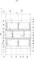
- FIG. 1 is a plan view of a tread portion 2 of a tire 1 according to the present embodiment.
- the tire 1 of the present embodiment is preferably used as a heavy-duty pneumatic tire.
- the present disclosure can also be adopted for the tire 1 for passenger cars and light trucks or airless tires which are not filled with air.
- the tread portion 2 includes a plurality of circumferential grooves 3 extending continuously in the tire circumferential direction and land portions 4 demarcated by the circumferential grooves 3.
- the circumferential grooves 3 include a pair of shoulder circumferential grooves 3A and at least one middle circumferential groove 3B disposed between the paired shoulder circumferential grooves 3A.
- the land portions 4 include a pair of outer land portions 4A disposed outward of the pair of shoulder circumferential grooves 3A in the tire axial direction, and two or more inner land portions 4B demarcated by the middle circumferential groove 3B between the paired shoulder circumferential grooves 3A.
- a higher ground contact pressure acts on the inner land portions 4B as compared with the outer land portions 4A during straight running.
- FIG. 2 is a cross-sectional view taken along a line A-A in FIG. 1 .
- a groove depth D2 of the middle circumferential groove 3B is formed so as to be less than a groove depth D1 of the shoulder circumferential groove 3A.
- stiffness of the inner land portions 4B disposed adjacent to the middle circumferential groove 3B is maintained to be high, and deformation of the inner land portion 4B during running with the tire is reduced, thereby enhancing rolling resistance performance.
- FIG. 3 is a perspective cross-sectional view of the middle circumferential groove 3B.
- a circumferential sipe 7 and a circumferential width-increased portion 9 are formed in a groove bottom 5B of the middle circumferential groove 3B.
- the circumferential sipe 7 extends inwardly from the groove bottom 5B in the tire radial direction.
- the circumferential width-increased portion 9 extends inwardly from the circumferential sipe 7 in the tire radial direction, and extends in the tire circumferential direction with a width w2 greater than a width of the circumferential sipe 7.
- the circumferential width-increased portion 9 allows enhancement of wet grip performance at an end stage of wear at which the circumferential width-increased portion 9 comes into contact with a road surface.
- “sipe” refers to a cut-like portion in which the width orthogonal to the longitudinal direction is not greater than 1.5 mm.
- “Groove” refers to a groove-like portion in which the groove width orthogonal to the longitudinal direction is greater than 1.5 mm.
- the tread portion 2 has two middle circumferential grooves 3B.
- the inner land portions 4B include a pair of first inner land portions 11 each demarcated by the shoulder circumferential groove 3A and the middle circumferential groove 3B, and a second inner land portion 12 demarcated by the two middle circumferential grooves 3B.
- the number of the middle circumferential grooves 3B may be greater than or equal to three.
- the middle circumferential grooves 3B are preferably disposed in a range defined from the tire equator C toward both sides in the tire axial direction so as to be less than or equal to 35% of a tread width TW.
- a water film at the land portion 4 near the tire equator C from which water is not easily drained can be effectively discharged.
- the middle circumferential grooves 3B are preferably disposed in a range that is distant by 20% or more of the tread width TW from the tire equator C toward both the sides in the tire axial direction.
- the tread width TW represents a distance in the tire axial direction between tread ends Te of the tire 1 in the normal state.
- the "normal state” represents a state in which the tire 1 is mounted on a normal rim (not shown) and is inflated to a normal internal pressure and no load is applied to the tire 1, in a case where various standards are defined for the tire 1.
- the normal state represents a standard use state, corresponding to a purpose of use of the tire 1, in which the tire 1 is not mounted to a vehicle and no load is applied to the tire 1.
- dimensions and the like of components of the tire 1 are represented by values measured in the normal state.
- the "normal rim” represents a rim that is defined by a standard, in a standard system including the standard on which the tire is based, for each tire, and is, for example, “standard rim” in the JATMA standard, "Design Rim” in the TRA standard, or “Measuring Rim” in the ETRTO standard.
- the "normal internal pressure” represents an air pressure that is defined by a standard, in a standard system including the standard on which the tire is based, for each tire, and is “maximum air pressure” in the JATMA standard, the maximum value recited in the table "TIRE LOAD LIMITS AT VARIOUS COLD INFLATION PRESSURES" in the TRA standard, or "INFLATION PRESSURE” in the ETRTO standard.
- the tread ends Te represent the outermost ground contact positions in the tire axial direction in a state where the normal load is applied to the tire 1 in the normal state and the tire 1 is in contact with a plane at a camber angle of 0°.
- the shoulder circumferential groove 3A is preferably disposed in a range defined from the tire equator C toward the outer side in the tire axial direction so as to be less than or equal to 37.5% of the tread width TW.
- the shoulder circumferential grooves 3A and the middle circumferential grooves 3B linearly extend.
- drainage resistance is reduced and wet grip performance can be enhanced.
- groove edges 8, 8 on both sides linearly extend.
- the shoulder circumferential groove 3A and the middle circumferential groove 3B may extend in a wavy manner or zigzag.
- the groove width W2 of the middle circumferential groove 3B is, but is not particularly limited to, preferably not less than 80% of a groove width W1 of the shoulder circumferential groove 3A and more preferably not less than 90% thereof, and preferably not greater than 120% thereof and more preferably not greater than 110% thereof.
- the groove depth D1 (shown in FIG. 2 ) of the shoulder circumferential groove 3A is, for example, 11.0 to 20.0 mm.
- the groove depth D2 of the middle circumferential groove 3B is preferably not less than 30% of the groove depth D1 of the shoulder circumferential groove 3A and more preferably not less than 40% thereof, and preferably not greater than 60% thereof and more preferably not greater than 50% thereof.
- the groove depth D2 of the middle circumferential groove 3B is, for example, preferably 3.0 to 12.0 mm.
- a cross-sectional area A2 of the middle circumferential groove 3B is 20% to 60% of a cross-sectional area A1 of the shoulder circumferential groove 3A. Since the cross-sectional area A2 of the middle circumferential groove 3B is not less than 20% of the cross-sectional area A1 of the shoulder circumferential groove 3A, wet grip performance is assured. Since the cross-sectional area A2 of the middle circumferential groove 3B is not greater than 60% of the cross-sectional area A1 of the shoulder circumferential groove 3A, high stiffness of the inner land portion 4B can be assured. From such a viewpoint, the cross-sectional area A2 of the middle circumferential groove 3B is more preferably not less than 30% of the cross-sectional area A1 of the shoulder circumferential groove 3A and more preferably not greater than 50% thereof.
- the circumferential sipe 7 is disposed only in the groove bottom 5B of the middle circumferential groove 3B.
- the shoulder circumferential groove 3A (groove bottom 5A of the shoulder circumferential groove 3A) does not have the circumferential sipe 7 and the circumferential width-increased portion 9.
- land portion stiffness is maintained in the outer land portion 4A and the inner land portion 4B on which a relatively high ground contact pressure acts, in a well-balanced manner, and degradation of rolling resistance performance is inhibited.
- a depth d1 of the circumferential sipe 7 is preferably 0.5 to 2.0 times a depth d2 of the circumferential width-increased portion 9. Since the depth d1 of the circumferential sipe 7 is not less than 0.5 times the depth d2 of the circumferential width-increased portion 9, stiffness of the inner land portion 4B can be further enhanced while a groove volume of the circumferential width-increased portion 9 is maintained. Since the depth d1 of the circumferential sipe 7 is not greater than 2.0 times the depth d2 of the circumferential width-increased portion 9, a groove volume of the circumferential width-increased portion 9 can be enhanced while stiffness of the inner land portion 4B is maintained.
- the depth d1 of the circumferential sipe 7 is, for example, preferably 40% to 80% of the groove depth D2 of the middle circumferential groove 3B.
- the circumferential sipe 7 is disposed at a position at which the groove bottom 5B has the maximum depth.
- the circumferential sipe 7 is, for example, disposed at a groove center line 3c of the middle circumferential groove 3B (shown in FIG. 1 ).
- the width w2 of the circumferential width-increased portion 9 is, but is not particularly limited to, preferably not less than 150% of a width w1 of the circumferential sipe 7 and more preferably not less than 200% thereof, and preferably not greater than 400% thereof and more preferably not greater than 350% thereof.
- the width w2 of the circumferential width-increased portion 9 is, for example, formed so as to be less than the groove width W2 of the middle circumferential groove 3B. Thus, stiffness of the inner land portion 4B is maintained and rolling resistance performance is enhanced. If the width w2 of the circumferential width-increased portion 9 is excessively small, an effect of enhancing wet grip performance may be reduced. Therefore, the width w2 of the circumferential width-increased portion 9 is, for example, preferably not less than 20% of the groove width W2 of the middle circumferential groove 3B and more preferably not less than 30% thereof, and preferably not greater than 65% thereof and more preferably not greater than 55% thereof.
- a cross-sectional area A3 of the circumferential width-increased portion 9 is preferably not less than 8% of the cross-sectional area A1 of the shoulder circumferential groove 3A and more preferably not less than 12% thereof, and preferably not greater than 24% thereof and more preferably not greater than 20% thereof.
- the cross-section of the circumferential width-increased portion 9 has an ellipsoidal shape. Thus, stiffness of each land portion 4 is maintained to be high.
- the shape of the circumferential width-increased portion 9 is not limited to such a shape, and may be, for example, round, rectangular, or triangular.
- a groove depth D3 of the total of the depths of the middle circumferential groove 3B, the circumferential sipe 7, and the circumferential width-increased portion 9 is preferably greater than the groove depth D1 of the shoulder circumferential groove 3A. Since the groove depth D3 is greater than the groove depth D1 of the shoulder circumferential groove 3A, reduction of stiffness of the outer land portion 4A is particularly inhibited, and balance with stiffness of the inner land portion 4B is maintained, whereby an effect of inhibiting degradation of rolling resistance performance is exhibited.
- At least one of the inner land portions 4B includes an axial sipe 15 extending in the tire axial direction, and an axial width-increased portion 16 extending inwardly from the axial sipe 15 in the tire radial direction and extending in the tire axial direction with a width w4 greater than a width of the axial sipe 15.
- the axial sipe 15 and the axial width-increased portion 16 having such structures enhance wet grip performance.
- the axial sipe 15 and the axial width-increased portion 16 are collectively referred to as an axial groove portion 17.
- the axial groove portion 17 is, for example, disposed in the first inner land portions 11 and the second inner land portion 12.
- Axial groove portions 17A of the first inner land portions 11 and axial groove portions 17B of the second inner land portion 12 are aligned in the tire circumferential direction.
- the axial groove portions 17 are not disposed in the outer land portions 4A.
- the axial groove portions 17A of the pair of first inner land portions 11 are, for example, disposed at the same positions in the tire circumferential direction.
- Each axial groove portion 17B of the second inner land portion 12 is displaced from the axial groove portion 17A of the first inner land portion 11 by half a pitch in the tire circumferential direction.
- the positions at which the axial groove portions 17A and the axial groove portions 17B are disposed are not limited to such positions.
- the axial sipe 15 is continuous with the shoulder circumferential groove 3A or the middle circumferential groove 3B.
- the axial groove portion 17 is continuous with the shoulder circumferential groove 3A or the middle circumferential groove 3B.
- water in the axial groove portion 17 is discharged into the shoulder circumferential groove 3A or the middle circumferential groove 3B, whereby wet grip performance is further enhanced.
- the axial sipe 15 is, for example, disposed at an angle ⁇ 1 of not greater than 30° relative to the tire axial direction.
- the axial groove portion 17 is disposed at an angle ⁇ 1 of not greater than 30° relative to the tire axial direction.
- the width w4 of the axial width-increased portion 16 is, but is not particularly limited to, preferably 2.0 to 4.0 times a width w3 of the axial sipe 15.
- a depth d3 of the axial sipe 15 is preferably 90% to 110% of the groove depth D2 of the middle circumferential groove 3B.
- the axial width-increased portion 16 is continuous with the circumferential sipe 7 or the shoulder circumferential groove 3A.
- an outer end e1 in the tire axial direction is continuous with the shoulder circumferential groove 3A and an inner end e2 is continuous with the circumferential sipe 7.
- Both ends of an axial width-increased portion 16B of the second inner land portion 12 are continuous with the circumferential sipes 7.
- a depth d4 of the axial width-increased portion 16 is preferably 90% to 110% of the depth d1 of the circumferential sipe 7.
- stiffness of the inner land portion 4B is maintained to be high by the circumferential sipe 7 and wet grip performance is enhanced by the axial width-increased portion 16. Therefore, in the present embodiment, the depth d4 of the axial width-increased portion 16 is equal to the depth d1 of the circumferential sipe 7.
- the outer land portion 4A is formed as a plain land portion having no sipes and grooves.
- the outer land portion 4A having such a structure has high stiffness and enhances rolling resistance performance.
- the outer land portion 4A is not limited to such a structure.
- the outer land portion 4A may include a shoulder lateral groove (not shown) having a groove depth of not greater than 2 mm.
- Tires having the basic pattern shown in FIG. 1 were produced. For each test tire, wet grip performance and rolling resistance performance were tested. Specifications common to the test tires and test methods were as follows.
- Rolling resistance performance was evaluated according to ECE R117-02 (ECE Regulation No. 117 Revision 2).
- the rolling resistance performance was evaluated by rolling resistance obtained when running with the test tire was performed on a pseudo road surface of an indoor drum tester. The evaluation is indicated as an index with rolling resistance value in comparative example 1 being 100. In the results, the less the value is, the more excellent rolling resistance performance is.
- wet grip performance was evaluated according to ECE R117-02.
- the wet grip performance was evaluated by a braking distance obtained when the test tires were mounted to a vehicle described below and the vehicle was caused to run on a road surface having specifications described below.
- the evaluation is indicated as an index with a braking distance in comparative example 1 being 100.
- the results at an initial stage of wear, an intermediate stage of wear, and an end stage of wear are indicated.
- Table 1 indicates the test results.
- Comp. Ex. 1 Comp. Ex. 2 Comp. Ex. 3 Comp. Ex. 4 Ex. 1 Ex. 2 Ex. 3 Ex. 4 Ex. 5 D2/D1 (%) 100 - - 50 35 50 55 50 50 A2/A1 (%) 100 - - 40 20 40 60 40 40 d1 (mm) - 20 10 - 6.5 5 4.5 3.3 6.6 d2 (mm) - - 10 - 6.5 5 4.5 6.6 3.3 dl/d2 (%) - - 100 - 100 100 100 50 200 Rolling resistance performance [index, the less the value is, the better the performance is] 100 80 80 85 80 83 85 85 80 Wet grip performance at initial stage of wear [index, the less the value is, the better the performance is] 100 110 110 100 100 100 100 100 100 100 100 Wet grip performance at intermediate stage of wear [index, the less the value is, the better the performance is] 100 105 110 110 100 100 100 100 100 100 Wet grip performance at end stage of wear [index, the less
- the present disclosure includes the following aspects.
- a tire including a tread portion, in which
- the circumferential sipe is disposed only in the groove bottom of the middle circumferential groove.
- the middle circumferential groove is disposed in a range defined from a tire equator toward both sides in a tire axial direction so as to be less than or equal to 35% of a tread width.
- the width of the circumferential width-increased portion is less than a groove width of the middle circumferential groove.
- a cross-sectional area of the middle circumferential groove is 20% to 60% of a cross-sectional area of each shoulder circumferential groove.
- a cross-sectional area of the circumferential width-increased portion is 8% to 24% of the cross-sectional area of each shoulder circumferential groove.
- a depth of the circumferential sipe is 0.5 to 2.0 times a depth of the circumferential width-increased portion.
- the axial sipe is continuous with a corresponding one of the shoulder circumferential grooves or the middle circumferential groove.
- the axial width-increased portion is continuous with the circumferential sipe or a corresponding one of the shoulder circumferential grooves.
- a depth of the axial sipe is 90% to 110% of the groove depth of the middle circumferential groove.
- a depth of the axial width-increased portion is 90% to 110% of the depth of the circumferential sipe.
- the axial sipe is disposed at an angle of not greater than 30° relative to the tire axial direction.
Landscapes
- Engineering & Computer Science (AREA)
- Mechanical Engineering (AREA)
- Tires In General (AREA)
Abstract
Description
- The present disclosure relates to a tire.
-
Japanese Laid-Open Patent Publication No. 2018-202956 - In recent years, rolling resistance performance and wet grip performance have been required to be further enhanced.
- The present disclosure has been made in view of the aforementioned circumstances, and a main object of the present disclosure is to provide a tire that exhibits excellent rolling resistance performance and wet grip performance.
- The present disclosure is directed to a tire that includes a tread portion. The tread portion includes a plurality of circumferential grooves extending continuously in a tire circumferential direction. The circumferential grooves include a pair of shoulder circumferential grooves, and at least one middle circumferential groove disposed between the pair of shoulder circumferential grooves. A groove depth of the middle circumferential groove is less than a groove depth of each of the shoulder circumferential grooves. In a groove bottom of the middle circumferential groove, a circumferential sipe extending inwardly from the groove bottom in a tire radial direction, and a circumferential width-increased portion extending inwardly from the circumferential sipe in the tire radial direction and extending in the tire circumferential direction with a width greater than a width of the circumferential sipe, are formed.
- The tire of the present disclosure has the above-described structures, and thus exhibits excellent rolling resistance performance and wet grip performance.
-
-
FIG. 1 is a plan view of a tire according to one embodiment of the present disclosure; -
FIG. 2 is a cross-sectional view taken along a line A-A inFIG. 1 ; and -
FIG. 3 is a perspective cross-sectional view of a middle circumferential groove. - One embodiment of the present disclosure will be described below with reference to the drawings.
-
FIG. 1 is a plan view of atread portion 2 of a tire 1 according to the present embodiment. The tire 1 of the present embodiment is preferably used as a heavy-duty pneumatic tire. However, the present disclosure can also be adopted for the tire 1 for passenger cars and light trucks or airless tires which are not filled with air. - As shown in
FIG. 1 , in the present embodiment, thetread portion 2 includes a plurality ofcircumferential grooves 3 extending continuously in the tire circumferential direction andland portions 4 demarcated by thecircumferential grooves 3. In the present embodiment, thecircumferential grooves 3 include a pair of shouldercircumferential grooves 3A and at least one middlecircumferential groove 3B disposed between the paired shouldercircumferential grooves 3A. In the present embodiment, theland portions 4 include a pair ofouter land portions 4A disposed outward of the pair of shouldercircumferential grooves 3A in the tire axial direction, and two or moreinner land portions 4B demarcated by the middlecircumferential groove 3B between the paired shouldercircumferential grooves 3A. A higher ground contact pressure acts on theinner land portions 4B as compared with theouter land portions 4A during straight running. -
FIG. 2 is a cross-sectional view taken along a line A-A inFIG. 1 . As shown inFIG. 2 , a groove depth D2 of the middlecircumferential groove 3B is formed so as to be less than a groove depth D1 of the shouldercircumferential groove 3A. Thus, stiffness of theinner land portions 4B disposed adjacent to the middlecircumferential groove 3B is maintained to be high, and deformation of theinner land portion 4B during running with the tire is reduced, thereby enhancing rolling resistance performance. -
FIG. 3 is a perspective cross-sectional view of the middlecircumferential groove 3B. As shown inFIG. 2 andFIG. 3 , in agroove bottom 5B of the middlecircumferential groove 3B, acircumferential sipe 7 and a circumferential width-increasedportion 9 are formed. In the present embodiment, thecircumferential sipe 7 extends inwardly from thegroove bottom 5B in the tire radial direction. In the present embodiment, the circumferential width-increasedportion 9 extends inwardly from thecircumferential sipe 7 in the tire radial direction, and extends in the tire circumferential direction with a width w2 greater than a width of thecircumferential sipe 7. Thus, reduction of an amount of water drained by the middlecircumferential groove 3B having a relatively small groove depth can be compensated for, whereby excellent rolling resistance performance and wet grip performance are exhibited. Particularly, the circumferential width-increasedportion 9 allows enhancement of wet grip performance at an end stage of wear at which the circumferential width-increasedportion 9 comes into contact with a road surface. In the description herein, "sipe" refers to a cut-like portion in which the width orthogonal to the longitudinal direction is not greater than 1.5 mm. "Groove" refers to a groove-like portion in which the groove width orthogonal to the longitudinal direction is greater than 1.5 mm. - As shown in
FIG. 1 , in the present embodiment, thetread portion 2 has two middlecircumferential grooves 3B. Thus, theinner land portions 4B include a pair of firstinner land portions 11 each demarcated by the shouldercircumferential groove 3A and the middlecircumferential groove 3B, and a secondinner land portion 12 demarcated by the two middlecircumferential grooves 3B. The number of the middlecircumferential grooves 3B may be greater than or equal to three. - For example, the middle
circumferential grooves 3B are preferably disposed in a range defined from the tire equator C toward both sides in the tire axial direction so as to be less than or equal to 35% of a tread width TW. Thus, a water film at theland portion 4 near the tire equator C from which water is not easily drained can be effectively discharged. In a case where thetread portion 2 has the two middlecircumferential grooves 3B, the middlecircumferential grooves 3B are preferably disposed in a range that is distant by 20% or more of the tread width TW from the tire equator C toward both the sides in the tire axial direction. - In the description herein, the tread width TW represents a distance in the tire axial direction between tread ends Te of the tire 1 in the normal state.
- The "normal state" represents a state in which the tire 1 is mounted on a normal rim (not shown) and is inflated to a normal internal pressure and no load is applied to the tire 1, in a case where various standards are defined for the tire 1. For the tires 1 for which various standards are not defined, the normal state represents a standard use state, corresponding to a purpose of use of the tire 1, in which the tire 1 is not mounted to a vehicle and no load is applied to the tire 1. In the description herein, unless otherwise specified, dimensions and the like of components of the tire 1 are represented by values measured in the normal state.
- The "normal rim" represents a rim that is defined by a standard, in a standard system including the standard on which the tire is based, for each tire, and is, for example, "standard rim" in the JATMA standard, "Design Rim" in the TRA standard, or "Measuring Rim" in the ETRTO standard.
- The "normal internal pressure" represents an air pressure that is defined by a standard, in a standard system including the standard on which the tire is based, for each tire, and is "maximum air pressure" in the JATMA standard, the maximum value recited in the table "TIRE LOAD LIMITS AT VARIOUS COLD INFLATION PRESSURES" in the TRA standard, or "INFLATION PRESSURE" in the ETRTO standard.
- In the description herein, the tread ends Te represent the outermost ground contact positions in the tire axial direction in a state where the normal load is applied to the tire 1 in the normal state and the tire 1 is in contact with a plane at a camber angle of 0°.
- The shoulder
circumferential groove 3A is preferably disposed in a range defined from the tire equator C toward the outer side in the tire axial direction so as to be less than or equal to 37.5% of the tread width TW. Thus, stiffness of theouter land portion 4A is assured and degradation of rolling resistance performance is inhibited. - In the present embodiment, the shoulder
circumferential grooves 3A and the middlecircumferential grooves 3B linearly extend. Thus, drainage resistance is reduced and wet grip performance can be enhanced. In the shouldercircumferential groove 3A and the middlecircumferential groove 3B,groove edges circumferential groove 3A and the middlecircumferential groove 3B may extend in a wavy manner or zigzag. - The groove width W2 of the middle
circumferential groove 3B is, but is not particularly limited to, preferably not less than 80% of a groove width W1 of the shouldercircumferential groove 3A and more preferably not less than 90% thereof, and preferably not greater than 120% thereof and more preferably not greater than 110% thereof. The groove depth D1 (shown inFIG. 2 ) of the shouldercircumferential groove 3A is, for example, 11.0 to 20.0 mm. - In
FIG. 2 , in a case where the groove depth D2 of the middlecircumferential groove 3B is excessively less than the groove depth D1 of the shouldercircumferential groove 3A, wet grip performance may be degraded. Therefore, the groove depth D2 of the middlecircumferential groove 3B is preferably not less than 30% of the groove depth D1 of the shouldercircumferential groove 3A and more preferably not less than 40% thereof, and preferably not greater than 60% thereof and more preferably not greater than 50% thereof. The groove depth D2 of the middlecircumferential groove 3B is, for example, preferably 3.0 to 12.0 mm. - In the present embodiment, a cross-sectional area A2 of the middle
circumferential groove 3B is 20% to 60% of a cross-sectional area A1 of theshoulder circumferential groove 3A. Since the cross-sectional area A2 of the middlecircumferential groove 3B is not less than 20% of the cross-sectional area A1 of theshoulder circumferential groove 3A, wet grip performance is assured. Since the cross-sectional area A2 of the middlecircumferential groove 3B is not greater than 60% of the cross-sectional area A1 of theshoulder circumferential groove 3A, high stiffness of theinner land portion 4B can be assured. From such a viewpoint, the cross-sectional area A2 of the middlecircumferential groove 3B is more preferably not less than 30% of the cross-sectional area A1 of theshoulder circumferential groove 3A and more preferably not greater than 50% thereof. - In the present embodiment, the
circumferential sipe 7 is disposed only in thegroove bottom 5B of the middlecircumferential groove 3B. In other words, theshoulder circumferential groove 3A (groove bottom 5A of theshoulder circumferential groove 3A) does not have thecircumferential sipe 7 and the circumferential width-increasedportion 9. Thus, land portion stiffness is maintained in theouter land portion 4A and theinner land portion 4B on which a relatively high ground contact pressure acts, in a well-balanced manner, and degradation of rolling resistance performance is inhibited. - As shown in
FIG. 3 , a depth d1 of thecircumferential sipe 7 is preferably 0.5 to 2.0 times a depth d2 of the circumferential width-increasedportion 9. Since the depth d1 of thecircumferential sipe 7 is not less than 0.5 times the depth d2 of the circumferential width-increasedportion 9, stiffness of theinner land portion 4B can be further enhanced while a groove volume of the circumferential width-increasedportion 9 is maintained. Since the depth d1 of thecircumferential sipe 7 is not greater than 2.0 times the depth d2 of the circumferential width-increasedportion 9, a groove volume of the circumferential width-increasedportion 9 can be enhanced while stiffness of theinner land portion 4B is maintained. The depth d1 of thecircumferential sipe 7 is, for example, preferably 40% to 80% of the groove depth D2 of the middlecircumferential groove 3B. - In the present embodiment, the
circumferential sipe 7 is disposed at a position at which thegroove bottom 5B has the maximum depth. Thus, water entering the groove smoothly flows into the circumferential width-increasedportion 9, whereby wet grip performance can be further enhanced. Thecircumferential sipe 7 is, for example, disposed at agroove center line 3c of the middlecircumferential groove 3B (shown inFIG. 1 ). - The width w2 of the circumferential width-increased
portion 9 is, but is not particularly limited to, preferably not less than 150% of a width w1 of thecircumferential sipe 7 and more preferably not less than 200% thereof, and preferably not greater than 400% thereof and more preferably not greater than 350% thereof. - The width w2 of the circumferential width-increased
portion 9 is, for example, formed so as to be less than the groove width W2 of the middlecircumferential groove 3B. Thus, stiffness of theinner land portion 4B is maintained and rolling resistance performance is enhanced. If the width w2 of the circumferential width-increasedportion 9 is excessively small, an effect of enhancing wet grip performance may be reduced. Therefore, the width w2 of the circumferential width-increasedportion 9 is, for example, preferably not less than 20% of the groove width W2 of the middlecircumferential groove 3B and more preferably not less than 30% thereof, and preferably not greater than 65% thereof and more preferably not greater than 55% thereof. - A cross-sectional area A3 of the circumferential width-increased
portion 9 is preferably not less than 8% of the cross-sectional area A1 of theshoulder circumferential groove 3A and more preferably not less than 12% thereof, and preferably not greater than 24% thereof and more preferably not greater than 20% thereof. Thus, the above-described effects are effectively exhibited. - The cross-section of the circumferential width-increased
portion 9 has an ellipsoidal shape. Thus, stiffness of eachland portion 4 is maintained to be high. The shape of the circumferential width-increasedportion 9 is not limited to such a shape, and may be, for example, round, rectangular, or triangular. - A groove depth D3 of the total of the depths of the middle
circumferential groove 3B, thecircumferential sipe 7, and the circumferential width-increasedportion 9 is preferably greater than the groove depth D1 of theshoulder circumferential groove 3A. Since the groove depth D3 is greater than the groove depth D1 of theshoulder circumferential groove 3A, reduction of stiffness of theouter land portion 4A is particularly inhibited, and balance with stiffness of theinner land portion 4B is maintained, whereby an effect of inhibiting degradation of rolling resistance performance is exhibited. - As shown in
FIG. 1 , at least one of theinner land portions 4B includes anaxial sipe 15 extending in the tire axial direction, and an axial width-increasedportion 16 extending inwardly from theaxial sipe 15 in the tire radial direction and extending in the tire axial direction with a width w4 greater than a width of theaxial sipe 15. Theaxial sipe 15 and the axial width-increasedportion 16 having such structures enhance wet grip performance. In the description herein, theaxial sipe 15 and the axial width-increasedportion 16 are collectively referred to as anaxial groove portion 17. - The
axial groove portion 17 is, for example, disposed in the firstinner land portions 11 and the secondinner land portion 12.Axial groove portions 17A of the firstinner land portions 11 and axial groove portions 17B of the secondinner land portion 12 are aligned in the tire circumferential direction. In the present embodiment, theaxial groove portions 17 are not disposed in theouter land portions 4A. - The
axial groove portions 17A of the pair of firstinner land portions 11 are, for example, disposed at the same positions in the tire circumferential direction. Each axial groove portion 17B of the secondinner land portion 12 is displaced from theaxial groove portion 17A of the firstinner land portion 11 by half a pitch in the tire circumferential direction. The positions at which theaxial groove portions 17A and the axial groove portions 17B are disposed are not limited to such positions. - In the present embodiment, the
axial sipe 15 is continuous with theshoulder circumferential groove 3A or the middlecircumferential groove 3B. In other words, theaxial groove portion 17 is continuous with theshoulder circumferential groove 3A or the middlecircumferential groove 3B. Thus, water in theaxial groove portion 17 is discharged into theshoulder circumferential groove 3A or the middlecircumferential groove 3B, whereby wet grip performance is further enhanced. - The
axial sipe 15 is, for example, disposed at an angle θ1 of not greater than 30° relative to the tire axial direction. In other words, theaxial groove portion 17 is disposed at an angle θ1 of not greater than 30° relative to the tire axial direction. Thus, stiffness of theinner land portion 4B in the tire axial direction is maintained to be high, and rolling resistance performance is enhanced. - The width w4 of the axial width-increased
portion 16 is, but is not particularly limited to, preferably 2.0 to 4.0 times a width w3 of theaxial sipe 15. - As shown in
FIG. 2 andFIG. 3 , a depth d3 of theaxial sipe 15 is preferably 90% to 110% of the groove depth D2 of the middlecircumferential groove 3B. Thus, in a period from a time when the tire 1 is new to an initial stage of wear at which the middlecircumferential groove 3B exists, reduction of stiffness of theinner land portion 4B is inhibited by theaxial sipe 15, and wet grip performance is maintained by the middlecircumferential groove 3B. Therefore, in the present embodiment, the depth d3 of theaxial sipe 15 is equal to the groove depth D2 of the middlecircumferential groove 3B. - In the present embodiment, the axial width-increased
portion 16 is continuous with thecircumferential sipe 7 or theshoulder circumferential groove 3A. As shown inFIG. 1 , in an axial width-increasedportion 16A of the firstinner land portion 11, for example, an outer end e1 in the tire axial direction is continuous with theshoulder circumferential groove 3A and an inner end e2 is continuous with thecircumferential sipe 7. Both ends of an axial width-increased portion 16B of the secondinner land portion 12 are continuous with thecircumferential sipes 7. - As shown in
FIG. 2 , a depth d4 of the axial width-increasedportion 16 is preferably 90% to 110% of the depth d1 of thecircumferential sipe 7. Thus, at an intermediate stage of wear from a time after disappearance of the middlecircumferential groove 3B to disappearance of thecircumferential sipe 7, stiffness of theinner land portion 4B is maintained to be high by thecircumferential sipe 7 and wet grip performance is enhanced by the axial width-increasedportion 16. Therefore, in the present embodiment, the depth d4 of the axial width-increasedportion 16 is equal to the depth d1 of thecircumferential sipe 7. - In the present embodiment, the
outer land portion 4A is formed as a plain land portion having no sipes and grooves. Theouter land portion 4A having such a structure has high stiffness and enhances rolling resistance performance. Theouter land portion 4A is not limited to such a structure. For example, theouter land portion 4A may include a shoulder lateral groove (not shown) having a groove depth of not greater than 2 mm. - Although the tire according to one embodiment of the present disclosure has been described in detail above, the present disclosure is not limited to the above-described specific embodiment, and various modifications can be made to implement the technique of the present disclosure.
- Tires having the basic pattern shown in
FIG. 1 were produced. For each test tire, wet grip performance and rolling resistance performance were tested. Specifications common to the test tires and test methods were as follows. - Tire size: 315/70R22.5
- Normal rim: 22.5×9.00
- Tire internal pressure: 900 kPa
- Groove depth D1 of shoulder circumferential groove: 14.5 mm
- Rolling resistance performance was evaluated according to ECE R117-02 (ECE Regulation No. 117 Revision 2). The rolling resistance performance was evaluated by rolling resistance obtained when running with the test tire was performed on a pseudo road surface of an indoor drum tester. The evaluation is indicated as an index with rolling resistance value in comparative example 1 being 100. In the results, the less the value is, the more excellent rolling resistance performance is.
- Load: 31.25 kN
- Running speed: 80 km/h
- Wet grip performance was evaluated according to ECE R117-02. The wet grip performance was evaluated by a braking distance obtained when the test tires were mounted to a vehicle described below and the vehicle was caused to run on a road surface having specifications described below. The evaluation is indicated as an index with a braking distance in comparative example 1 being 100. In the results, the less the value is, the more excellent wet grip performance is. Furthermore, the results at an initial stage of wear, an intermediate stage of wear, and an end stage of wear are indicated.
- Road surface: asphalt road surface having a water depth of 0.5 to 2.0 mm
- Vehicle: 10-ton truck (loaded with cargo corresponding to 75% of standard payload)
- Braking distance: distance until stop of the vehicle running at a speed of 65±2 km/h
- Table 1 indicates the test results.
[Table 1] Comp. Ex. 1 Comp. Ex. 2 Comp. Ex. 3 Comp. Ex. 4 Ex. 1 Ex. 2 Ex. 3 Ex. 4 Ex. 5 D2/D1 (%) 100 - - 50 35 50 55 50 50 A2/A1 (%) 100 - - 40 20 40 60 40 40 d1 (mm) - 20 10 - 6.5 5 4.5 3.3 6.6 d2 (mm) - - 10 - 6.5 5 4.5 6.6 3.3 dl/d2 (%) - - 100 - 100 100 100 50 200 Rolling resistance performance [index, the less the value is, the better the performance is] 100 80 80 85 80 83 85 85 80 Wet grip performance at initial stage of wear [index, the less the value is, the better the performance is] 100 110 110 100 100 100 100 100 100 Wet grip performance at intermediate stage of wear [index, the less the value is, the better the performance is] 100 105 110 110 100 100 100 100 100 Wet grip performance at end stage of wear [index, the less the value is, the better the performance is] 100 105 100 110 100 100 100 100 100 - According to the test results, it was confirmed that the tires of the examples exhibited excellent rolling resistance performance and wet grip performance.
- The present disclosure includes the following aspects.
- A tire including a tread portion, in which
- the tread portion includes a plurality of circumferential grooves extending continuously in a tire circumferential direction,
- the circumferential grooves include a pair of shoulder circumferential grooves, and at least one middle circumferential groove disposed between the pair of shoulder circumferential grooves,
- a groove depth of the middle circumferential groove is less than a groove depth of each of the shoulder circumferential grooves, and
- in a groove bottom of the middle circumferential groove, a circumferential sipe extending inwardly from the groove bottom in a tire radial direction, and a circumferential width-increased portion extending inwardly from the circumferential sipe in the tire radial direction and extending in the tire circumferential direction with a width greater than a width of the circumferential sipe, are formed.
- In the tire according to disclosure 1, the circumferential sipe is disposed only in the groove bottom of the middle circumferential groove.
- In the tire according to
disclosure 1 or 2, the middle circumferential groove is disposed in a range defined from a tire equator toward both sides in a tire axial direction so as to be less than or equal to 35% of a tread width. - In the tire according to any one of disclosures 1 to 3, the width of the circumferential width-increased portion is less than a groove width of the middle circumferential groove.
- In the tire according to any one of disclosures 1 to 4, a cross-sectional area of the middle circumferential groove is 20% to 60% of a cross-sectional area of each shoulder circumferential groove.
- In the tire according to any one of disclosures 1 to 5, a cross-sectional area of the circumferential width-increased portion is 8% to 24% of the cross-sectional area of each shoulder circumferential groove.
- In the tire according to any one of disclosures 1 to 6, a depth of the circumferential sipe is 0.5 to 2.0 times a depth of the circumferential width-increased portion.
- In the tire according to any one of disclosures 1 to 7,
- the tread portion includes land portions demarcated by the circumferential grooves,
- the land portions include two or more inner land portions demarcated by the middle circumferential groove between the pair of shoulder circumferential grooves, and
- at least one of the inner land portions includes an axial sipe extending in the tire axial direction, and an axial width-increased portion extending inwardly from the axial sipe in the tire radial direction and extending in the tire axial direction with a width greater than a width of the axial sipe.
- In the tire according to
disclosure 8, the axial sipe is continuous with a corresponding one of the shoulder circumferential grooves or the middle circumferential groove. - In the tire according to
disclosure - In the tire according to any one of
disclosures 8 to 10, a depth of the axial sipe is 90% to 110% of the groove depth of the middle circumferential groove. - In the tire according to any one of
disclosures 8 to 11, a depth of the axial width-increased portion is 90% to 110% of the depth of the circumferential sipe. - In the tire according to any one of
disclosures 8 to 12, the axial sipe is disposed at an angle of not greater than 30° relative to the tire axial direction.
Claims (13)
- A tire (1) comprisinga tread portion (2), whereinthe tread portion (2) includes a plurality of circumferential grooves (3) extending continuously in a tire circumferential direction,the circumferential grooves (3) include a pair of shoulder circumferential grooves (3A), and at least one middle circumferential groove (3B) disposed between the pair of shoulder circumferential grooves (3A),a groove depth (D2) of the middle circumferential groove (3B) is less than a groove depth (D1) of each of the shoulder circumferential grooves (3A), andin a groove bottom (5B) of the middle circumferential groove (3B), a circumferential sipe (7) extending inwardly from the groove bottom (5B) in a tire radial direction, and a circumferential width-increased portion (9) extending inwardly from the circumferential sipe (7) in the tire radial direction and extending in the tire circumferential direction with a width (w2) greater than a width of the circumferential sipe (7), are formed.
- The tire (1) according to claim 1, wherein the circumferential sipe (7) is disposed only in the groove bottom (5B) of the middle circumferential groove (3B).
- The tire (1) according to claim 1 or 2, wherein the middle circumferential groove (3B) is disposed in a range defined from a tire equator (C) toward both sides in a tire axial direction so as to be less than or equal to 35% of a tread width (TW).
- The tire (1) according to any one of claims 1 to 3, wherein the width (w2) of the circumferential width-increased portion (9) is less than a groove width (W2) of the middle circumferential groove (3B).
- The tire (1) according to any one of claims 1 to 4, wherein a cross-sectional area (A2) of the middle circumferential groove (3B) is 20% to 60% of a cross-sectional area (A1) of each shoulder circumferential groove (3A).
- The tire (1) according to any one of claims 1 to 5, wherein a cross-sectional area (A3) of the circumferential width-increased portion (9) is 8% to 24% of the cross-sectional area (A1) of each shoulder circumferential groove (3A).
- The tire (1) according to any one of claims 1 to 6, wherein a depth (d1) of the circumferential sipe (7) is 0.5 to 2.0 times a depth (d2) of the circumferential width-increased portion (9).
- The tire (1) according to any one of claims 1 to 7, whereinthe tread portion (2) includes land portions (4) demarcated by the circumferential grooves (3),the land portions (4) include two or more inner land portions (4B) demarcated by the middle circumferential groove (3B) between the pair of shoulder circumferential grooves (3A), andat least one of the inner land portions (4B) includes an axial sipe (15) extending in the tire axial direction, and an axial width-increased portion (16) extending inwardly from the axial sipe (15) in the tire radial direction and extending in the tire axial direction with a width (w4) greater than a width of the axial sipe (15).
- The tire (1) according to claim 8, wherein the axial sipe (15) is continuous with a corresponding one of the shoulder circumferential grooves (3A) or the middle circumferential groove (3B).
- The tire (1) according to claim 8 or 9, wherein the axial width-increased portion (16) is continuous with the circumferential sipe (7) or a corresponding one of the shoulder circumferential grooves (3A).
- The tire (1) according to any one of claims 8 to 10, wherein a depth (d3) of the axial sipe (15) is 90% to 110% of the groove depth (D2) of the middle circumferential groove (3B).
- The tire (1) according to any one of claims 8 to 11, wherein a depth (d4) of the axial width-increased portion (16) is 90% to 110% of the depth (d1) of the circumferential sipe (7).
- The tire (1) according to any one of claims 8 to 12, wherein the axial sipe (15) is disposed at an angle θ1 of not greater than 30° relative to the tire axial direction.
Applications Claiming Priority (1)
| Application Number | Priority Date | Filing Date | Title |
|---|---|---|---|
| JP2021130865A JP7711476B2 (en) | 2021-08-10 | 2021-08-10 | tire |
Publications (2)
| Publication Number | Publication Date |
|---|---|
| EP4134250A1 true EP4134250A1 (en) | 2023-02-15 |
| EP4134250B1 EP4134250B1 (en) | 2024-01-24 |
Family
ID=82748285
Family Applications (1)
| Application Number | Title | Priority Date | Filing Date |
|---|---|---|---|
| EP22187379.7A Active EP4134250B1 (en) | 2021-08-10 | 2022-07-28 | Tire |
Country Status (2)
| Country | Link |
|---|---|
| EP (1) | EP4134250B1 (en) |
| JP (1) | JP7711476B2 (en) |
Cited By (2)
| Publication number | Priority date | Publication date | Assignee | Title |
|---|---|---|---|---|
| EP4613504A1 (en) * | 2024-03-07 | 2025-09-10 | Sumitomo Rubber Industries, Ltd. | Heavy duty tire |
| EP4699817A1 (en) | 2024-08-12 | 2026-02-25 | The Goodyear Tire & Rubber Company | Tire tread with a bottom groove and a reinforcing structure with angles |
Citations (5)
| Publication number | Priority date | Publication date | Assignee | Title |
|---|---|---|---|---|
| WO2013150143A1 (en) * | 2012-04-05 | 2013-10-10 | Compagnie Generale Des Etablissements Michelin | Heavy goods vehicle driven axle tyre tread |
| WO2017176280A1 (en) * | 2016-04-08 | 2017-10-12 | Compagnie Generale Des Etablissements Michelin | Truck tire tread and truck tire |
| JP2018202956A (en) | 2017-06-01 | 2018-12-27 | 株式会社ブリヂストン | Pneumatic tire |
| EP3492283A1 (en) * | 2017-12-01 | 2019-06-05 | The Goodyear Tire & Rubber Company | Tire tread comprising a stabilizer structure |
| EP3974208A1 (en) * | 2020-09-24 | 2022-03-30 | Continental Reifen Deutschland GmbH | Vehicle tyres |
Family Cites Families (1)
| Publication number | Priority date | Publication date | Assignee | Title |
|---|---|---|---|---|
| JP2010058696A (en) | 2008-09-04 | 2010-03-18 | Bridgestone Corp | Tire |
-
2021
- 2021-08-10 JP JP2021130865A patent/JP7711476B2/en active Active
-
2022
- 2022-07-28 EP EP22187379.7A patent/EP4134250B1/en active Active
Patent Citations (5)
| Publication number | Priority date | Publication date | Assignee | Title |
|---|---|---|---|---|
| WO2013150143A1 (en) * | 2012-04-05 | 2013-10-10 | Compagnie Generale Des Etablissements Michelin | Heavy goods vehicle driven axle tyre tread |
| WO2017176280A1 (en) * | 2016-04-08 | 2017-10-12 | Compagnie Generale Des Etablissements Michelin | Truck tire tread and truck tire |
| JP2018202956A (en) | 2017-06-01 | 2018-12-27 | 株式会社ブリヂストン | Pneumatic tire |
| EP3492283A1 (en) * | 2017-12-01 | 2019-06-05 | The Goodyear Tire & Rubber Company | Tire tread comprising a stabilizer structure |
| EP3974208A1 (en) * | 2020-09-24 | 2022-03-30 | Continental Reifen Deutschland GmbH | Vehicle tyres |
Cited By (2)
| Publication number | Priority date | Publication date | Assignee | Title |
|---|---|---|---|---|
| EP4613504A1 (en) * | 2024-03-07 | 2025-09-10 | Sumitomo Rubber Industries, Ltd. | Heavy duty tire |
| EP4699817A1 (en) | 2024-08-12 | 2026-02-25 | The Goodyear Tire & Rubber Company | Tire tread with a bottom groove and a reinforcing structure with angles |
Also Published As
| Publication number | Publication date |
|---|---|
| JP2023025551A (en) | 2023-02-22 |
| EP4134250B1 (en) | 2024-01-24 |
| JP7711476B2 (en) | 2025-07-23 |
Similar Documents
| Publication | Publication Date | Title |
|---|---|---|
| EP2583839B1 (en) | Heavy duty tyre | |
| EP2578418B1 (en) | Pneumatic tire | |
| EP3153334B1 (en) | Tire | |
| EP3296127B1 (en) | Pneumatic tire | |
| EP3118026B1 (en) | Pneumatic tire | |
| US8267133B2 (en) | Pneumatic tire | |
| EP2289714B1 (en) | Pneumatic tire | |
| EP2457744B1 (en) | Pneumatic tire | |
| US9090134B2 (en) | Pneumatic tire | |
| EP3012119B1 (en) | Pneumatic tire | |
| EP2311659B1 (en) | Pneumatic tire | |
| EP3260308A1 (en) | Tire | |
| EP3318421B1 (en) | Tire | |
| EP3572243B1 (en) | Tire | |
| EP3744539B1 (en) | Tire | |
| US10173476B2 (en) | Pneumatic tire | |
| EP3064378A1 (en) | Pneumatic tire | |
| EP4134250A1 (en) | Tire | |
| US11458775B2 (en) | Pneumatic tyre, tyre mold and method for manufacturing pneumatic tyre using the same | |
| US20200198408A1 (en) | Tire | |
| EP3552846B1 (en) | Tyre | |
| EP3970996B1 (en) | Tire | |
| EP3689644B1 (en) | Tire | |
| US20220161605A1 (en) | Tire | |
| US12472781B2 (en) | Heavy duty tire |
Legal Events
| Date | Code | Title | Description |
|---|---|---|---|
| PUAI | Public reference made under article 153(3) epc to a published international application that has entered the european phase |
Free format text: ORIGINAL CODE: 0009012 |
|
| STAA | Information on the status of an ep patent application or granted ep patent |
Free format text: STATUS: THE APPLICATION HAS BEEN PUBLISHED |
|
| AK | Designated contracting states |
Kind code of ref document: A1 Designated state(s): AL AT BE BG CH CY CZ DE DK EE ES FI FR GB GR HR HU IE IS IT LI LT LU LV MC MK MT NL NO PL PT RO RS SE SI SK SM TR |
|
| STAA | Information on the status of an ep patent application or granted ep patent |
Free format text: STATUS: REQUEST FOR EXAMINATION WAS MADE |
|
| 17P | Request for examination filed |
Effective date: 20230421 |
|
| RBV | Designated contracting states (corrected) |
Designated state(s): AL AT BE BG CH CY CZ DE DK EE ES FI FR GB GR HR HU IE IS IT LI LT LU LV MC MK MT NL NO PL PT RO RS SE SI SK SM TR |
|
| P01 | Opt-out of the competence of the unified patent court (upc) registered |
Effective date: 20230510 |
|
| GRAP | Despatch of communication of intention to grant a patent |
Free format text: ORIGINAL CODE: EPIDOSNIGR1 |
|
| STAA | Information on the status of an ep patent application or granted ep patent |
Free format text: STATUS: GRANT OF PATENT IS INTENDED |
|
| INTG | Intention to grant announced |
Effective date: 20231018 |
|
| RAP3 | Party data changed (applicant data changed or rights of an application transferred) |
Owner name: SUMITOMO RUBBER INDUSTRIES, LTD. |
|
| GRAS | Grant fee paid |
Free format text: ORIGINAL CODE: EPIDOSNIGR3 |
|
| GRAA | (expected) grant |
Free format text: ORIGINAL CODE: 0009210 |
|
| STAA | Information on the status of an ep patent application or granted ep patent |
Free format text: STATUS: THE PATENT HAS BEEN GRANTED |
|
| AK | Designated contracting states |
Kind code of ref document: B1 Designated state(s): AL AT BE BG CH CY CZ DE DK EE ES FI FR GB GR HR HU IE IS IT LI LT LU LV MC MK MT NL NO PL PT RO RS SE SI SK SM TR |
|
| REG | Reference to a national code |
Ref country code: GB Ref legal event code: FG4D |
|
| REG | Reference to a national code |
Ref country code: CH Ref legal event code: EP |
|
| REG | Reference to a national code |
Ref country code: IE Ref legal event code: FG4D |
|
| REG | Reference to a national code |
Ref country code: DE Ref legal event code: R096 Ref document number: 602022001687 Country of ref document: DE |
|
| REG | Reference to a national code |
Ref country code: LT Ref legal event code: MG9D |
|
| REG | Reference to a national code |
Ref country code: NL Ref legal event code: MP Effective date: 20240124 |
|
| PG25 | Lapsed in a contracting state [announced via postgrant information from national office to epo] |
Ref country code: NL Free format text: LAPSE BECAUSE OF FAILURE TO SUBMIT A TRANSLATION OF THE DESCRIPTION OR TO PAY THE FEE WITHIN THE PRESCRIBED TIME-LIMIT Effective date: 20240124 |
|
| PG25 | Lapsed in a contracting state [announced via postgrant information from national office to epo] |
Ref country code: NL Free format text: LAPSE BECAUSE OF FAILURE TO SUBMIT A TRANSLATION OF THE DESCRIPTION OR TO PAY THE FEE WITHIN THE PRESCRIBED TIME-LIMIT Effective date: 20240124 |
|
| PG25 | Lapsed in a contracting state [announced via postgrant information from national office to epo] |
Ref country code: IS Free format text: LAPSE BECAUSE OF FAILURE TO SUBMIT A TRANSLATION OF THE DESCRIPTION OR TO PAY THE FEE WITHIN THE PRESCRIBED TIME-LIMIT Effective date: 20240524 |
|
| PG25 | Lapsed in a contracting state [announced via postgrant information from national office to epo] |
Ref country code: LT Free format text: LAPSE BECAUSE OF FAILURE TO SUBMIT A TRANSLATION OF THE DESCRIPTION OR TO PAY THE FEE WITHIN THE PRESCRIBED TIME-LIMIT Effective date: 20240124 |
|
| PG25 | Lapsed in a contracting state [announced via postgrant information from national office to epo] |
Ref country code: GR Free format text: LAPSE BECAUSE OF FAILURE TO SUBMIT A TRANSLATION OF THE DESCRIPTION OR TO PAY THE FEE WITHIN THE PRESCRIBED TIME-LIMIT Effective date: 20240425 |
|
| REG | Reference to a national code |
Ref country code: AT Ref legal event code: MK05 Ref document number: 1651904 Country of ref document: AT Kind code of ref document: T Effective date: 20240124 |
|
| PG25 | Lapsed in a contracting state [announced via postgrant information from national office to epo] |
Ref country code: RS Free format text: LAPSE BECAUSE OF FAILURE TO SUBMIT A TRANSLATION OF THE DESCRIPTION OR TO PAY THE FEE WITHIN THE PRESCRIBED TIME-LIMIT Effective date: 20240424 Ref country code: HR Free format text: LAPSE BECAUSE OF FAILURE TO SUBMIT A TRANSLATION OF THE DESCRIPTION OR TO PAY THE FEE WITHIN THE PRESCRIBED TIME-LIMIT Effective date: 20240124 |
|
| PG25 | Lapsed in a contracting state [announced via postgrant information from national office to epo] |
Ref country code: ES Free format text: LAPSE BECAUSE OF FAILURE TO SUBMIT A TRANSLATION OF THE DESCRIPTION OR TO PAY THE FEE WITHIN THE PRESCRIBED TIME-LIMIT Effective date: 20240124 |
|
| PG25 | Lapsed in a contracting state [announced via postgrant information from national office to epo] |
Ref country code: AT Free format text: LAPSE BECAUSE OF FAILURE TO SUBMIT A TRANSLATION OF THE DESCRIPTION OR TO PAY THE FEE WITHIN THE PRESCRIBED TIME-LIMIT Effective date: 20240124 |
|
| PG25 | Lapsed in a contracting state [announced via postgrant information from national office to epo] |
Ref country code: RS Free format text: LAPSE BECAUSE OF FAILURE TO SUBMIT A TRANSLATION OF THE DESCRIPTION OR TO PAY THE FEE WITHIN THE PRESCRIBED TIME-LIMIT Effective date: 20240424 Ref country code: NO Free format text: LAPSE BECAUSE OF FAILURE TO SUBMIT A TRANSLATION OF THE DESCRIPTION OR TO PAY THE FEE WITHIN THE PRESCRIBED TIME-LIMIT Effective date: 20240424 Ref country code: LT Free format text: LAPSE BECAUSE OF FAILURE TO SUBMIT A TRANSLATION OF THE DESCRIPTION OR TO PAY THE FEE WITHIN THE PRESCRIBED TIME-LIMIT Effective date: 20240124 Ref country code: IS Free format text: LAPSE BECAUSE OF FAILURE TO SUBMIT A TRANSLATION OF THE DESCRIPTION OR TO PAY THE FEE WITHIN THE PRESCRIBED TIME-LIMIT Effective date: 20240524 Ref country code: HR Free format text: LAPSE BECAUSE OF FAILURE TO SUBMIT A TRANSLATION OF THE DESCRIPTION OR TO PAY THE FEE WITHIN THE PRESCRIBED TIME-LIMIT Effective date: 20240124 Ref country code: GR Free format text: LAPSE BECAUSE OF FAILURE TO SUBMIT A TRANSLATION OF THE DESCRIPTION OR TO PAY THE FEE WITHIN THE PRESCRIBED TIME-LIMIT Effective date: 20240425 Ref country code: FI Free format text: LAPSE BECAUSE OF FAILURE TO SUBMIT A TRANSLATION OF THE DESCRIPTION OR TO PAY THE FEE WITHIN THE PRESCRIBED TIME-LIMIT Effective date: 20240124 Ref country code: ES Free format text: LAPSE BECAUSE OF FAILURE TO SUBMIT A TRANSLATION OF THE DESCRIPTION OR TO PAY THE FEE WITHIN THE PRESCRIBED TIME-LIMIT Effective date: 20240124 Ref country code: BG Free format text: LAPSE BECAUSE OF FAILURE TO SUBMIT A TRANSLATION OF THE DESCRIPTION OR TO PAY THE FEE WITHIN THE PRESCRIBED TIME-LIMIT Effective date: 20240124 Ref country code: AT Free format text: LAPSE BECAUSE OF FAILURE TO SUBMIT A TRANSLATION OF THE DESCRIPTION OR TO PAY THE FEE WITHIN THE PRESCRIBED TIME-LIMIT Effective date: 20240124 |
|
| PG25 | Lapsed in a contracting state [announced via postgrant information from national office to epo] |
Ref country code: PT Free format text: LAPSE BECAUSE OF FAILURE TO SUBMIT A TRANSLATION OF THE DESCRIPTION OR TO PAY THE FEE WITHIN THE PRESCRIBED TIME-LIMIT Effective date: 20240524 Ref country code: PL Free format text: LAPSE BECAUSE OF FAILURE TO SUBMIT A TRANSLATION OF THE DESCRIPTION OR TO PAY THE FEE WITHIN THE PRESCRIBED TIME-LIMIT Effective date: 20240124 |
|
| PG25 | Lapsed in a contracting state [announced via postgrant information from national office to epo] |
Ref country code: SE Free format text: LAPSE BECAUSE OF FAILURE TO SUBMIT A TRANSLATION OF THE DESCRIPTION OR TO PAY THE FEE WITHIN THE PRESCRIBED TIME-LIMIT Effective date: 20240124 Ref country code: PT Free format text: LAPSE BECAUSE OF FAILURE TO SUBMIT A TRANSLATION OF THE DESCRIPTION OR TO PAY THE FEE WITHIN THE PRESCRIBED TIME-LIMIT Effective date: 20240524 Ref country code: PL Free format text: LAPSE BECAUSE OF FAILURE TO SUBMIT A TRANSLATION OF THE DESCRIPTION OR TO PAY THE FEE WITHIN THE PRESCRIBED TIME-LIMIT Effective date: 20240124 Ref country code: LV Free format text: LAPSE BECAUSE OF FAILURE TO SUBMIT A TRANSLATION OF THE DESCRIPTION OR TO PAY THE FEE WITHIN THE PRESCRIBED TIME-LIMIT Effective date: 20240124 |
|
| PG25 | Lapsed in a contracting state [announced via postgrant information from national office to epo] |
Ref country code: DK Free format text: LAPSE BECAUSE OF FAILURE TO SUBMIT A TRANSLATION OF THE DESCRIPTION OR TO PAY THE FEE WITHIN THE PRESCRIBED TIME-LIMIT Effective date: 20240124 |
|
| PG25 | Lapsed in a contracting state [announced via postgrant information from national office to epo] |
Ref country code: SM Free format text: LAPSE BECAUSE OF FAILURE TO SUBMIT A TRANSLATION OF THE DESCRIPTION OR TO PAY THE FEE WITHIN THE PRESCRIBED TIME-LIMIT Effective date: 20240124 |
|
| PG25 | Lapsed in a contracting state [announced via postgrant information from national office to epo] |
Ref country code: CZ Free format text: LAPSE BECAUSE OF FAILURE TO SUBMIT A TRANSLATION OF THE DESCRIPTION OR TO PAY THE FEE WITHIN THE PRESCRIBED TIME-LIMIT Effective date: 20240124 Ref country code: EE Free format text: LAPSE BECAUSE OF FAILURE TO SUBMIT A TRANSLATION OF THE DESCRIPTION OR TO PAY THE FEE WITHIN THE PRESCRIBED TIME-LIMIT Effective date: 20240124 |
|
| REG | Reference to a national code |
Ref country code: DE Ref legal event code: R097 Ref document number: 602022001687 Country of ref document: DE |
|
| PG25 | Lapsed in a contracting state [announced via postgrant information from national office to epo] |
Ref country code: SK Free format text: LAPSE BECAUSE OF FAILURE TO SUBMIT A TRANSLATION OF THE DESCRIPTION OR TO PAY THE FEE WITHIN THE PRESCRIBED TIME-LIMIT Effective date: 20240124 |
|
| PG25 | Lapsed in a contracting state [announced via postgrant information from national office to epo] |
Ref country code: SM Free format text: LAPSE BECAUSE OF FAILURE TO SUBMIT A TRANSLATION OF THE DESCRIPTION OR TO PAY THE FEE WITHIN THE PRESCRIBED TIME-LIMIT Effective date: 20240124 Ref country code: SK Free format text: LAPSE BECAUSE OF FAILURE TO SUBMIT A TRANSLATION OF THE DESCRIPTION OR TO PAY THE FEE WITHIN THE PRESCRIBED TIME-LIMIT Effective date: 20240124 Ref country code: EE Free format text: LAPSE BECAUSE OF FAILURE TO SUBMIT A TRANSLATION OF THE DESCRIPTION OR TO PAY THE FEE WITHIN THE PRESCRIBED TIME-LIMIT Effective date: 20240124 Ref country code: DK Free format text: LAPSE BECAUSE OF FAILURE TO SUBMIT A TRANSLATION OF THE DESCRIPTION OR TO PAY THE FEE WITHIN THE PRESCRIBED TIME-LIMIT Effective date: 20240124 Ref country code: CZ Free format text: LAPSE BECAUSE OF FAILURE TO SUBMIT A TRANSLATION OF THE DESCRIPTION OR TO PAY THE FEE WITHIN THE PRESCRIBED TIME-LIMIT Effective date: 20240124 |
|
| PLBE | No opposition filed within time limit |
Free format text: ORIGINAL CODE: 0009261 |
|
| STAA | Information on the status of an ep patent application or granted ep patent |
Free format text: STATUS: NO OPPOSITION FILED WITHIN TIME LIMIT |
|
| PG25 | Lapsed in a contracting state [announced via postgrant information from national office to epo] |
Ref country code: IT Free format text: LAPSE BECAUSE OF FAILURE TO SUBMIT A TRANSLATION OF THE DESCRIPTION OR TO PAY THE FEE WITHIN THE PRESCRIBED TIME-LIMIT Effective date: 20240124 |
|
| PG25 | Lapsed in a contracting state [announced via postgrant information from national office to epo] |
Ref country code: IT Free format text: LAPSE BECAUSE OF FAILURE TO SUBMIT A TRANSLATION OF THE DESCRIPTION OR TO PAY THE FEE WITHIN THE PRESCRIBED TIME-LIMIT Effective date: 20240124 |
|
| 26N | No opposition filed |
Effective date: 20241025 |
|
| PG25 | Lapsed in a contracting state [announced via postgrant information from national office to epo] |
Ref country code: MC Free format text: LAPSE BECAUSE OF FAILURE TO SUBMIT A TRANSLATION OF THE DESCRIPTION OR TO PAY THE FEE WITHIN THE PRESCRIBED TIME-LIMIT Effective date: 20240124 |
|
| PG25 | Lapsed in a contracting state [announced via postgrant information from national office to epo] |
Ref country code: LU Free format text: LAPSE BECAUSE OF NON-PAYMENT OF DUE FEES Effective date: 20240728 |
|
| PG25 | Lapsed in a contracting state [announced via postgrant information from national office to epo] |
Ref country code: LU Free format text: LAPSE BECAUSE OF NON-PAYMENT OF DUE FEES Effective date: 20240728 |
|
| PG25 | Lapsed in a contracting state [announced via postgrant information from national office to epo] |
Ref country code: SI Free format text: LAPSE BECAUSE OF FAILURE TO SUBMIT A TRANSLATION OF THE DESCRIPTION OR TO PAY THE FEE WITHIN THE PRESCRIBED TIME-LIMIT Effective date: 20240124 Ref country code: BE Free format text: LAPSE BECAUSE OF NON-PAYMENT OF DUE FEES Effective date: 20240731 |
|
| REG | Reference to a national code |
Ref country code: BE Ref legal event code: MM Effective date: 20240731 |
|
| PGFP | Annual fee paid to national office [announced via postgrant information from national office to epo] |
Ref country code: FR Payment date: 20250610 Year of fee payment: 4 |
|
| PG25 | Lapsed in a contracting state [announced via postgrant information from national office to epo] |
Ref country code: IE Free format text: LAPSE BECAUSE OF NON-PAYMENT OF DUE FEES Effective date: 20240728 |
|
| PGFP | Annual fee paid to national office [announced via postgrant information from national office to epo] |
Ref country code: DE Payment date: 20250604 Year of fee payment: 4 |
|
| PG25 | Lapsed in a contracting state [announced via postgrant information from national office to epo] |
Ref country code: RO Free format text: LAPSE BECAUSE OF FAILURE TO SUBMIT A TRANSLATION OF THE DESCRIPTION OR TO PAY THE FEE WITHIN THE PRESCRIBED TIME-LIMIT Effective date: 20240124 |
|
| PG25 | Lapsed in a contracting state [announced via postgrant information from national office to epo] |
Ref country code: CY Free format text: LAPSE BECAUSE OF FAILURE TO SUBMIT A TRANSLATION OF THE DESCRIPTION OR TO PAY THE FEE WITHIN THE PRESCRIBED TIME-LIMIT; INVALID AB INITIO Effective date: 20220728 |
|
| REG | Reference to a national code |
Ref country code: CH Ref legal event code: H13 Free format text: ST27 STATUS EVENT CODE: U-0-0-H10-H13 (AS PROVIDED BY THE NATIONAL OFFICE) Effective date: 20260224 |
|
| PG25 | Lapsed in a contracting state [announced via postgrant information from national office to epo] |
Ref country code: HU Free format text: LAPSE BECAUSE OF FAILURE TO SUBMIT A TRANSLATION OF THE DESCRIPTION OR TO PAY THE FEE WITHIN THE PRESCRIBED TIME-LIMIT; INVALID AB INITIO Effective date: 20220728 |
|
| PG25 | Lapsed in a contracting state [announced via postgrant information from national office to epo] |
Ref country code: CH Free format text: LAPSE BECAUSE OF NON-PAYMENT OF DUE FEES Effective date: 20250731 |