EP4134152A1 - Electrochemical metal removal - Google Patents
Electrochemical metal removal Download PDFInfo
- Publication number
- EP4134152A1 EP4134152A1 EP21190802.5A EP21190802A EP4134152A1 EP 4134152 A1 EP4134152 A1 EP 4134152A1 EP 21190802 A EP21190802 A EP 21190802A EP 4134152 A1 EP4134152 A1 EP 4134152A1
- Authority
- EP
- European Patent Office
- Prior art keywords
- solvent
- rich
- lean
- metal
- inlet
- Prior art date
- Legal status (The legal status is an assumption and is not a legal conclusion. Google has not performed a legal analysis and makes no representation as to the accuracy of the status listed.)
- Withdrawn
Links
- 229910052751 metal Inorganic materials 0.000 title claims description 48
- 239000002184 metal Substances 0.000 title claims description 48
- 238000000034 method Methods 0.000 claims abstract description 58
- 229910001428 transition metal ion Inorganic materials 0.000 claims abstract description 17
- 239000002904 solvent Substances 0.000 claims description 119
- 239000012530 fluid Substances 0.000 claims description 42
- XEEYBQQBJWHFJM-UHFFFAOYSA-N iron Substances [Fe] XEEYBQQBJWHFJM-UHFFFAOYSA-N 0.000 claims description 41
- -1 iron cations Chemical class 0.000 claims description 36
- 239000012528 membrane Substances 0.000 claims description 24
- 229910052742 iron Inorganic materials 0.000 claims description 23
- 229910021645 metal ion Inorganic materials 0.000 claims description 22
- 230000002829 reductive effect Effects 0.000 claims description 20
- 150000001412 amines Chemical class 0.000 claims description 18
- 239000006096 absorbing agent Substances 0.000 claims description 17
- 239000007788 liquid Substances 0.000 claims description 17
- HZAXFHJVJLSVMW-UHFFFAOYSA-N 2-Aminoethan-1-ol Chemical compound NCCO HZAXFHJVJLSVMW-UHFFFAOYSA-N 0.000 claims description 16
- PXHVJJICTQNCMI-UHFFFAOYSA-N nickel Substances [Ni] PXHVJJICTQNCMI-UHFFFAOYSA-N 0.000 claims description 15
- 239000011651 chromium Substances 0.000 claims description 10
- 238000005349 anion exchange Methods 0.000 claims description 9
- GLUUGHFHXGJENI-UHFFFAOYSA-N Piperazine Chemical compound C1CNCCN1 GLUUGHFHXGJENI-UHFFFAOYSA-N 0.000 claims description 8
- 238000005341 cation exchange Methods 0.000 claims description 7
- 239000011572 manganese Substances 0.000 claims description 7
- 229910052759 nickel Inorganic materials 0.000 claims description 7
- CBTVGIZVANVGBH-UHFFFAOYSA-N aminomethyl propanol Chemical compound CC(C)(N)CO CBTVGIZVANVGBH-UHFFFAOYSA-N 0.000 claims description 6
- 229910052804 chromium Inorganic materials 0.000 claims description 6
- 229910052723 transition metal Inorganic materials 0.000 claims description 5
- LYCAIKOWRPUZTN-UHFFFAOYSA-N Ethylene glycol Chemical compound OCCO LYCAIKOWRPUZTN-UHFFFAOYSA-N 0.000 claims description 4
- 150000003624 transition metals Chemical class 0.000 claims description 4
- 229910017052 cobalt Inorganic materials 0.000 claims description 3
- 239000010941 cobalt Substances 0.000 claims description 3
- 229910052748 manganese Inorganic materials 0.000 claims description 3
- CRVGTESFCCXCTH-UHFFFAOYSA-N methyl diethanolamine Chemical compound OCCN(C)CCO CRVGTESFCCXCTH-UHFFFAOYSA-N 0.000 claims description 3
- 239000000203 mixture Substances 0.000 claims description 3
- 150000001413 amino acids Chemical class 0.000 claims description 2
- 238000011437 continuous method Methods 0.000 claims description 2
- WGCNASOHLSPBMP-UHFFFAOYSA-N hydroxyacetaldehyde Natural products OCC=O WGCNASOHLSPBMP-UHFFFAOYSA-N 0.000 claims description 2
- 230000008021 deposition Effects 0.000 claims 1
- CURLTUGMZLYLDI-UHFFFAOYSA-N Carbon dioxide Chemical compound O=C=O CURLTUGMZLYLDI-UHFFFAOYSA-N 0.000 description 74
- 229910002092 carbon dioxide Inorganic materials 0.000 description 69
- 239000007789 gas Substances 0.000 description 16
- OKTJSMMVPCPJKN-UHFFFAOYSA-N Carbon Chemical compound [C] OKTJSMMVPCPJKN-UHFFFAOYSA-N 0.000 description 15
- 239000000243 solution Substances 0.000 description 14
- 230000015556 catabolic process Effects 0.000 description 13
- 238000006731 degradation reaction Methods 0.000 description 13
- CWYNVVGOOAEACU-UHFFFAOYSA-N Fe2+ Chemical compound [Fe+2] CWYNVVGOOAEACU-UHFFFAOYSA-N 0.000 description 12
- 230000008569 process Effects 0.000 description 11
- 230000009467 reduction Effects 0.000 description 11
- 150000001768 cations Chemical class 0.000 description 6
- 239000012466 permeate Substances 0.000 description 6
- 239000001569 carbon dioxide Substances 0.000 description 5
- 239000002738 chelating agent Substances 0.000 description 5
- 239000007857 degradation product Substances 0.000 description 5
- 229910002804 graphite Inorganic materials 0.000 description 5
- 239000010439 graphite Substances 0.000 description 5
- 238000005260 corrosion Methods 0.000 description 4
- 230000007797 corrosion Effects 0.000 description 4
- 239000003792 electrolyte Substances 0.000 description 4
- 238000002474 experimental method Methods 0.000 description 4
- 239000003456 ion exchange resin Substances 0.000 description 4
- 229920003303 ion-exchange polymer Polymers 0.000 description 4
- 239000000463 material Substances 0.000 description 4
- 150000002739 metals Chemical class 0.000 description 4
- 238000010525 oxidative degradation reaction Methods 0.000 description 4
- 230000008929 regeneration Effects 0.000 description 4
- 238000011069 regeneration method Methods 0.000 description 4
- 150000003839 salts Chemical class 0.000 description 4
- 241000894007 species Species 0.000 description 4
- 229910001220 stainless steel Inorganic materials 0.000 description 4
- 239000010935 stainless steel Substances 0.000 description 4
- XLYOFNOQVPJJNP-UHFFFAOYSA-N water Substances O XLYOFNOQVPJJNP-UHFFFAOYSA-N 0.000 description 4
- KXDHJXZQYSOELW-UHFFFAOYSA-M Carbamate Chemical compound NC([O-])=O KXDHJXZQYSOELW-UHFFFAOYSA-M 0.000 description 3
- VTLYFUHAOXGGBS-UHFFFAOYSA-N Fe3+ Chemical compound [Fe+3] VTLYFUHAOXGGBS-UHFFFAOYSA-N 0.000 description 3
- 229910021607 Silver chloride Inorganic materials 0.000 description 3
- 239000003957 anion exchange resin Substances 0.000 description 3
- 150000001450 anions Chemical class 0.000 description 3
- 239000003125 aqueous solvent Substances 0.000 description 3
- QVGXLLKOCUKJST-UHFFFAOYSA-N atomic oxygen Chemical compound [O] QVGXLLKOCUKJST-UHFFFAOYSA-N 0.000 description 3
- 125000002091 cationic group Chemical group 0.000 description 3
- 238000000909 electrodialysis Methods 0.000 description 3
- 239000001301 oxygen Substances 0.000 description 3
- 229910052760 oxygen Inorganic materials 0.000 description 3
- 239000011347 resin Substances 0.000 description 3
- 229920005989 resin Polymers 0.000 description 3
- HKZLPVFGJNLROG-UHFFFAOYSA-M silver monochloride Chemical compound [Cl-].[Ag+] HKZLPVFGJNLROG-UHFFFAOYSA-M 0.000 description 3
- 239000002699 waste material Substances 0.000 description 3
- QGZKDVFQNNGYKY-UHFFFAOYSA-N Ammonia Chemical compound N QGZKDVFQNNGYKY-UHFFFAOYSA-N 0.000 description 2
- UQSXHKLRYXJYBZ-UHFFFAOYSA-N Iron oxide Chemical compound [Fe]=O UQSXHKLRYXJYBZ-UHFFFAOYSA-N 0.000 description 2
- WAEMQWOKJMHJLA-UHFFFAOYSA-N Manganese(2+) Chemical compound [Mn+2] WAEMQWOKJMHJLA-UHFFFAOYSA-N 0.000 description 2
- 230000002378 acidificating effect Effects 0.000 description 2
- 125000000129 anionic group Chemical group 0.000 description 2
- 239000007864 aqueous solution Substances 0.000 description 2
- 229910052799 carbon Inorganic materials 0.000 description 2
- BVKZGUZCCUSVTD-UHFFFAOYSA-N carbonic acid Chemical compound OC(O)=O BVKZGUZCCUSVTD-UHFFFAOYSA-N 0.000 description 2
- 230000006652 catabolic pathway Effects 0.000 description 2
- 238000006243 chemical reaction Methods 0.000 description 2
- BFGKITSFLPAWGI-UHFFFAOYSA-N chromium(3+) Chemical compound [Cr+3] BFGKITSFLPAWGI-UHFFFAOYSA-N 0.000 description 2
- JOPOVCBBYLSVDA-UHFFFAOYSA-N chromium(6+) Chemical compound [Cr+6] JOPOVCBBYLSVDA-UHFFFAOYSA-N 0.000 description 2
- 230000000694 effects Effects 0.000 description 2
- 238000001914 filtration Methods 0.000 description 2
- XLYOFNOQVPJJNP-UHFFFAOYSA-M hydroxide Chemical compound [OH-] XLYOFNOQVPJJNP-UHFFFAOYSA-M 0.000 description 2
- 239000012535 impurity Substances 0.000 description 2
- 150000002500 ions Chemical class 0.000 description 2
- 229910044991 metal oxide Inorganic materials 0.000 description 2
- VNWKTOKETHGBQD-UHFFFAOYSA-N methane Chemical compound C VNWKTOKETHGBQD-UHFFFAOYSA-N 0.000 description 2
- 230000007935 neutral effect Effects 0.000 description 2
- 230000003647 oxidation Effects 0.000 description 2
- 238000007254 oxidation reaction Methods 0.000 description 2
- 238000000746 purification Methods 0.000 description 2
- PVXVWWANJIWJOO-UHFFFAOYSA-N 1-(1,3-benzodioxol-5-yl)-N-ethylpropan-2-amine Chemical compound CCNC(C)CC1=CC=C2OCOC2=C1 PVXVWWANJIWJOO-UHFFFAOYSA-N 0.000 description 1
- IJGRMHOSHXDMSA-UHFFFAOYSA-N Atomic nitrogen Chemical compound N#N IJGRMHOSHXDMSA-UHFFFAOYSA-N 0.000 description 1
- BVKZGUZCCUSVTD-UHFFFAOYSA-M Bicarbonate Chemical compound OC([O-])=O BVKZGUZCCUSVTD-UHFFFAOYSA-M 0.000 description 1
- UGFAIRIUMAVXCW-UHFFFAOYSA-N Carbon monoxide Chemical compound [O+]#[C-] UGFAIRIUMAVXCW-UHFFFAOYSA-N 0.000 description 1
- BVKZGUZCCUSVTD-UHFFFAOYSA-L Carbonate Chemical compound [O-]C([O-])=O BVKZGUZCCUSVTD-UHFFFAOYSA-L 0.000 description 1
- VYZAMTAEIAYCRO-UHFFFAOYSA-N Chromium Chemical compound [Cr] VYZAMTAEIAYCRO-UHFFFAOYSA-N 0.000 description 1
- MYMOFIZGZYHOMD-UHFFFAOYSA-N Dioxygen Chemical compound O=O MYMOFIZGZYHOMD-UHFFFAOYSA-N 0.000 description 1
- QMMZSJPSPRTHGB-UHFFFAOYSA-N MDEA Natural products CC(C)CCCCC=CCC=CC(O)=O QMMZSJPSPRTHGB-UHFFFAOYSA-N 0.000 description 1
- PWHULOQIROXLJO-UHFFFAOYSA-N Manganese Chemical compound [Mn] PWHULOQIROXLJO-UHFFFAOYSA-N 0.000 description 1
- RTAQQCXQSZGOHL-UHFFFAOYSA-N Titanium Chemical compound [Ti] RTAQQCXQSZGOHL-UHFFFAOYSA-N 0.000 description 1
- 238000010521 absorption reaction Methods 0.000 description 1
- 239000002253 acid Substances 0.000 description 1
- 150000007513 acids Chemical class 0.000 description 1
- 229910021529 ammonia Inorganic materials 0.000 description 1
- 239000003011 anion exchange membrane Substances 0.000 description 1
- 239000003054 catalyst Substances 0.000 description 1
- 239000010406 cathode material Substances 0.000 description 1
- 239000003729 cation exchange resin Substances 0.000 description 1
- 229940023913 cation exchange resins Drugs 0.000 description 1
- 230000008859 change Effects 0.000 description 1
- 150000001875 compounds Chemical class 0.000 description 1
- 239000000356 contaminant Substances 0.000 description 1
- 150000004696 coordination complex Chemical class 0.000 description 1
- 230000001419 dependent effect Effects 0.000 description 1
- 229910001882 dioxygen Inorganic materials 0.000 description 1
- 239000003480 eluent Substances 0.000 description 1
- 238000005516 engineering process Methods 0.000 description 1
- 230000002349 favourable effect Effects 0.000 description 1
- 239000003546 flue gas Substances 0.000 description 1
- 239000005431 greenhouse gas Substances 0.000 description 1
- 239000002920 hazardous waste Substances 0.000 description 1
- 238000011065 in-situ storage Methods 0.000 description 1
- 235000014413 iron hydroxide Nutrition 0.000 description 1
- IEECXTSVVFWGSE-UHFFFAOYSA-M iron(3+);oxygen(2-);hydroxide Chemical compound [OH-].[O-2].[Fe+3] IEECXTSVVFWGSE-UHFFFAOYSA-M 0.000 description 1
- NCNCGGDMXMBVIA-UHFFFAOYSA-L iron(ii) hydroxide Chemical compound [OH-].[OH-].[Fe+2] NCNCGGDMXMBVIA-UHFFFAOYSA-L 0.000 description 1
- 230000007774 longterm Effects 0.000 description 1
- MMIPFLVOWGHZQD-UHFFFAOYSA-N manganese(3+) Chemical compound [Mn+3] MMIPFLVOWGHZQD-UHFFFAOYSA-N 0.000 description 1
- 238000004519 manufacturing process Methods 0.000 description 1
- 230000007246 mechanism Effects 0.000 description 1
- 238000009285 membrane fouling Methods 0.000 description 1
- 229910000000 metal hydroxide Inorganic materials 0.000 description 1
- 150000004692 metal hydroxides Chemical class 0.000 description 1
- 150000004706 metal oxides Chemical class 0.000 description 1
- 239000003345 natural gas Substances 0.000 description 1
- 230000001590 oxidative effect Effects 0.000 description 1
- 238000012856 packing Methods 0.000 description 1
- 239000002244 precipitate Substances 0.000 description 1
- 239000000047 product Substances 0.000 description 1
- 238000007790 scraping Methods 0.000 description 1
- 239000000126 substance Substances 0.000 description 1
- 239000010936 titanium Substances 0.000 description 1
- 229910052719 titanium Inorganic materials 0.000 description 1
Images







Classifications
-
- B—PERFORMING OPERATIONS; TRANSPORTING
- B01—PHYSICAL OR CHEMICAL PROCESSES OR APPARATUS IN GENERAL
- B01D—SEPARATION
- B01D53/00—Separation of gases or vapours; Recovering vapours of volatile solvents from gases; Chemical or biological purification of waste gases, e.g. engine exhaust gases, smoke, fumes, flue gases, aerosols
- B01D53/34—Chemical or biological purification of waste gases
- B01D53/96—Regeneration, reactivation or recycling of reactants
- B01D53/965—Regeneration, reactivation or recycling of reactants including an electrochemical process step
-
- B—PERFORMING OPERATIONS; TRANSPORTING
- B01—PHYSICAL OR CHEMICAL PROCESSES OR APPARATUS IN GENERAL
- B01D—SEPARATION
- B01D53/00—Separation of gases or vapours; Recovering vapours of volatile solvents from gases; Chemical or biological purification of waste gases, e.g. engine exhaust gases, smoke, fumes, flue gases, aerosols
- B01D53/14—Separation of gases or vapours; Recovering vapours of volatile solvents from gases; Chemical or biological purification of waste gases, e.g. engine exhaust gases, smoke, fumes, flue gases, aerosols by absorption
- B01D53/1425—Regeneration of liquid absorbents
-
- B—PERFORMING OPERATIONS; TRANSPORTING
- B01—PHYSICAL OR CHEMICAL PROCESSES OR APPARATUS IN GENERAL
- B01D—SEPARATION
- B01D53/00—Separation of gases or vapours; Recovering vapours of volatile solvents from gases; Chemical or biological purification of waste gases, e.g. engine exhaust gases, smoke, fumes, flue gases, aerosols
- B01D53/14—Separation of gases or vapours; Recovering vapours of volatile solvents from gases; Chemical or biological purification of waste gases, e.g. engine exhaust gases, smoke, fumes, flue gases, aerosols by absorption
- B01D53/1456—Removing acid components
- B01D53/1475—Removing carbon dioxide
-
- B—PERFORMING OPERATIONS; TRANSPORTING
- B01—PHYSICAL OR CHEMICAL PROCESSES OR APPARATUS IN GENERAL
- B01D—SEPARATION
- B01D53/00—Separation of gases or vapours; Recovering vapours of volatile solvents from gases; Chemical or biological purification of waste gases, e.g. engine exhaust gases, smoke, fumes, flue gases, aerosols
- B01D53/14—Separation of gases or vapours; Recovering vapours of volatile solvents from gases; Chemical or biological purification of waste gases, e.g. engine exhaust gases, smoke, fumes, flue gases, aerosols by absorption
- B01D53/1493—Selection of liquid materials for use as absorbents
-
- B—PERFORMING OPERATIONS; TRANSPORTING
- B01—PHYSICAL OR CHEMICAL PROCESSES OR APPARATUS IN GENERAL
- B01D—SEPARATION
- B01D53/00—Separation of gases or vapours; Recovering vapours of volatile solvents from gases; Chemical or biological purification of waste gases, e.g. engine exhaust gases, smoke, fumes, flue gases, aerosols
- B01D53/34—Chemical or biological purification of waste gases
- B01D53/46—Removing components of defined structure
- B01D53/62—Carbon oxides
-
- B—PERFORMING OPERATIONS; TRANSPORTING
- B01—PHYSICAL OR CHEMICAL PROCESSES OR APPARATUS IN GENERAL
- B01D—SEPARATION
- B01D53/00—Separation of gases or vapours; Recovering vapours of volatile solvents from gases; Chemical or biological purification of waste gases, e.g. engine exhaust gases, smoke, fumes, flue gases, aerosols
- B01D53/34—Chemical or biological purification of waste gases
- B01D53/74—General processes for purification of waste gases; Apparatus or devices specially adapted therefor
- B01D53/77—Liquid phase processes
- B01D53/78—Liquid phase processes with gas-liquid contact
-
- B—PERFORMING OPERATIONS; TRANSPORTING
- B01—PHYSICAL OR CHEMICAL PROCESSES OR APPARATUS IN GENERAL
- B01D—SEPARATION
- B01D61/00—Processes of separation using semi-permeable membranes, e.g. dialysis, osmosis or ultrafiltration; Apparatus, accessories or auxiliary operations specially adapted therefor
- B01D61/42—Electrodialysis; Electro-osmosis ; Electro-ultrafiltration; Membrane capacitive deionization
- B01D61/44—Ion-selective electrodialysis
- B01D61/445—Ion-selective electrodialysis with bipolar membranes; Water splitting
-
- B—PERFORMING OPERATIONS; TRANSPORTING
- B01—PHYSICAL OR CHEMICAL PROCESSES OR APPARATUS IN GENERAL
- B01D—SEPARATION
- B01D61/00—Processes of separation using semi-permeable membranes, e.g. dialysis, osmosis or ultrafiltration; Apparatus, accessories or auxiliary operations specially adapted therefor
- B01D61/42—Electrodialysis; Electro-osmosis ; Electro-ultrafiltration; Membrane capacitive deionization
- B01D61/44—Ion-selective electrodialysis
- B01D61/46—Apparatus therefor
- B01D61/463—Apparatus therefor comprising the membrane sequence AC or CA, where C is a cation exchange membrane
-
- B—PERFORMING OPERATIONS; TRANSPORTING
- B01—PHYSICAL OR CHEMICAL PROCESSES OR APPARATUS IN GENERAL
- B01D—SEPARATION
- B01D2252/00—Absorbents, i.e. solvents and liquid materials for gas absorption
- B01D2252/20—Organic absorbents
- B01D2252/202—Alcohols or their derivatives
- B01D2252/2023—Glycols, diols or their derivatives
-
- B—PERFORMING OPERATIONS; TRANSPORTING
- B01—PHYSICAL OR CHEMICAL PROCESSES OR APPARATUS IN GENERAL
- B01D—SEPARATION
- B01D2252/00—Absorbents, i.e. solvents and liquid materials for gas absorption
- B01D2252/20—Organic absorbents
- B01D2252/204—Amines
- B01D2252/20405—Monoamines
-
- B—PERFORMING OPERATIONS; TRANSPORTING
- B01—PHYSICAL OR CHEMICAL PROCESSES OR APPARATUS IN GENERAL
- B01D—SEPARATION
- B01D2252/00—Absorbents, i.e. solvents and liquid materials for gas absorption
- B01D2252/20—Organic absorbents
- B01D2252/204—Amines
- B01D2252/20421—Primary amines
-
- B—PERFORMING OPERATIONS; TRANSPORTING
- B01—PHYSICAL OR CHEMICAL PROCESSES OR APPARATUS IN GENERAL
- B01D—SEPARATION
- B01D2252/00—Absorbents, i.e. solvents and liquid materials for gas absorption
- B01D2252/20—Organic absorbents
- B01D2252/204—Amines
- B01D2252/20436—Cyclic amines
- B01D2252/20447—Cyclic amines containing a piperazine-ring
-
- B—PERFORMING OPERATIONS; TRANSPORTING
- B01—PHYSICAL OR CHEMICAL PROCESSES OR APPARATUS IN GENERAL
- B01D—SEPARATION
- B01D2252/00—Absorbents, i.e. solvents and liquid materials for gas absorption
- B01D2252/20—Organic absorbents
- B01D2252/204—Amines
- B01D2252/20478—Alkanolamines
- B01D2252/20484—Alkanolamines with one hydroxyl group
-
- B—PERFORMING OPERATIONS; TRANSPORTING
- B01—PHYSICAL OR CHEMICAL PROCESSES OR APPARATUS IN GENERAL
- B01D—SEPARATION
- B01D2257/00—Components to be removed
- B01D2257/50—Carbon oxides
- B01D2257/504—Carbon dioxide
-
- C—CHEMISTRY; METALLURGY
- C25—ELECTROLYTIC OR ELECTROPHORETIC PROCESSES; APPARATUS THEREFOR
- C25D—PROCESSES FOR THE ELECTROLYTIC OR ELECTROPHORETIC PRODUCTION OF COATINGS; ELECTROFORMING; APPARATUS THEREFOR
- C25D5/00—Electroplating characterised by the process; Pretreatment or after-treatment of workpieces
- C25D5/003—Electroplating using gases, e.g. pressure influence
-
- Y—GENERAL TAGGING OF NEW TECHNOLOGICAL DEVELOPMENTS; GENERAL TAGGING OF CROSS-SECTIONAL TECHNOLOGIES SPANNING OVER SEVERAL SECTIONS OF THE IPC; TECHNICAL SUBJECTS COVERED BY FORMER USPC CROSS-REFERENCE ART COLLECTIONS [XRACs] AND DIGESTS
- Y02—TECHNOLOGIES OR APPLICATIONS FOR MITIGATION OR ADAPTATION AGAINST CLIMATE CHANGE
- Y02C—CAPTURE, STORAGE, SEQUESTRATION OR DISPOSAL OF GREENHOUSE GASES [GHG]
- Y02C20/00—Capture or disposal of greenhouse gases
- Y02C20/40—Capture or disposal of greenhouse gases of CO2
Definitions
- the invention is in the field of CO 2 capture.
- the invention relates to a method to remove metal ions from a solvent from CO 2 capture processes, and a system for the method.
- a method to minimize emission is to capture and optionally regenerate the carbon dioxide.
- Conventional CO 2 capture include processes as described in US1783901 and for absorption based technologies the carbon dioxide containing gas (e.g. a flue gas) is fed to an absorber wherein it is contacted with a solvent.
- the solvent are typically amine-based aqueous solvents, such as alkanolamines.
- the CO 2 reacts with the solvent to form i.a. carbamate and/or carbonate and/or bicarbonate ions and protonated alkanolamines, and a CO 2 -lean gas which leaves the absorber.
- the CO 2 -rich stream can be fed to a regenerator (e.g. stripper), wherein typically a reboiler is present at the bottom to remove the CO 2 from the solvent.
- a regenerator e.g. stripper
- the highest temperature in the regenerator is around 120°C.
- the high temperature in the stripper can cause degradation of the amine (thermal degradation).
- the feed gas typically comprises oxygen and the presence of oxygen cause solvent degradation (e.g. through an oxidative degradation pathway).
- the oxidative degradation pathway is the main degradation mechanism and it is responsible for about 70% of total amine losses. This may be severe and a wide variety of volatile products (e.g. ammonia) and heat-stable salts can be formed.
- the degradation products can be corrosive to the material of the CO 2 capture plant (i.a. absorber, regenerator, pipes), which typically comprise stainless steel.
- the corrosion may be monitored by the amount of metal that originate from the material of the CO 2 capture plant.
- the particular metals and what metal may be predominantly present may for instance depend on i.a. the type of stainless steel and/or the degree of stainless steel.
- iron, chromium and nickel can be found as dissolved ions in the capture solvent.
- the dissolved metal ions can further be considered as a catalyst for the oxidative degradation, which will subsequently lead to more degradation and that will lead to more corrosivity of the solvent. This cycle can be considered as an autocatalytic process.
- Reclaiming processes can be employed. Reclaiming processes are typically operated batch-wise and may be costly.
- thermal reclaiming An example of a solvent reclaiming process is thermal reclaiming, wherein heat is used to distill a part of the non-degraded solvent (e.g. amines) from the solution.
- a solvent reclaiming process thermal reclaiming, wherein heat is used to distill a part of the non-degraded solvent (e.g. amines) from the solution.
- more solvent may degrade during the reclaiming and thermal reclaiming is typically paired with significant losses of the non-reclaimed solvent.
- thermal reclaiming is energy intensive and typically results in a hazardous waste stream comprising impurities, degradation products and salts.
- a further drawback is the limited throughput, roughly 1-2% of the total solvent flow can be subjected to thermal reclaiming.
- Another method comprises ion-exchange resins, which are often used to remove charged contaminants.
- the principle is based on the use of cation exchange resins to replace cationic species with protons and anion exchange resins to replace anionic species with hydroxyl ions.
- An example hereof is disclosed in US4795565 .
- heat stable salts are removed from ethanolamine gas purification process units using ion-exchange resins.
- anion exchange resins is disclosed in EP0430432 .
- an alkanolamine solution containing heat stable alkanolamine salts of acidic anions is contacted with an anion exchange resin to remove the acidic anions. Small amounts of metal cations may also be captured by the resin.
- ion-exchange resins may require aggressive regeneration cycles, typically leading to large amounts of strong acids and bases that have to be recycled or disposed of. Accordingly, the use of ion-exchange resins may be paired with increasing complexity of the solvent and waste management. Additionally, there is typically a risk that some of the carbamate ions and protonated alkanolamines are captured by the resins.
- Electrodialysis can be employed to remove charged species from aqueous solvents.
- a stack of alternating cation exchange membranes and anion exchange membranes are typically used to drive charged species through the selectively permeable membranes under an applied potential difference.
- a drawback of using electrodialysis is membrane fouling which increases ohmic resistance and accordingly reduces efficiency.
- the carbamate ions and protonated amines may permeate through the membranes leading to a loss of solvent. This may be particularly unbeneficial at high CO 2 loading as a high concentration of carbamate and protonated amines may be present.
- Activated carbon is also a proposed solution to remove degradation products from CO 2 capture solvents.
- the throughput is variable, from approximately 1-2% up to 10-20% of the total solvent flow.
- the activated carbon typically needs to be replaced or regenerated. As the activated carbon may absorb degradation compounds safety issues are typically associated with replacing the activated carbon.
- the present invention is directed to a method for CO 2 capture from a CO 2 -containing feed gas stream (10).
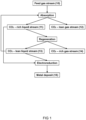
- the method is schematically illustrated as flow-chart in Figure 1 .
- the method accordingly comprises providing the feed gas stream in an absorber (101) comprising an solvent to absorb CO 2 in the solvent to obtain a CO 2 -rich solvent stream (11) and a CO 2 -lean gas stream (12).
- the solvent typically reacts with the CO 2 present in the feed gas.
- the CO 2 -rich solvent stream can be led to a regenerator (104). In the regenerator the reaction of the solvent with CO 2 is typically reversed to obtain a CO 2 -lean solvent stream (13) and a CO 2 -rich gas stream (14).
- the CO 2 -lean solvent stream is preferably led back to the absorber.
- oxygen is present in the feed gas which may cause solvent degradation.
- the solvent degradation products can be corrosive. This can lead to the generation of metal ions into solution.
- the origin of the metal ions can be from the metallic parts of the capture plant (e.g. absorber, heat exchangers, stripper, piping, packing material).
- the CO 2 -rich solvent stream and/or the CO 2 -lean solvent stream comprise dissolved transition metal ions.
- the method further comprises at least partially removing these dissolved transition metal ions. Removal of the dissolved metal ions comprises electroreduction of the dissolved transition metal ions in an electrochemical cell (1) to obtain a metal deposit (15).
- the method may be performed at ambient temperature and pressure, but as well at temperature and pressure conditions present in the capture plant.
- the method according to the present invention may allow for a reduced waste management, avoid fast degradation of the solvents and increase the lifetime of both solvent and industrial equipment.
- the CO 2 -containing feed gas stream may be any feed gas that comprises carbon dioxide. Examples include, but are not limited to flue gasses from industrial processes, air, exhaust gasses and natural gas.
- the feed gasses may further comprise other gasses such as molecular oxygen and/or molecular nitrogen.
- the feed gas enters an absorber in which during use a solvent is provided and reacts with the carbon dioxide to absorb the CO 2 .
- solvents typically comprise amine-based solvents.
- the solvent comprises a CO 2 capture solvent (i.e. a liquid that reacts with the CO 2 ), herein also referred to as capture solvent.
- CO 2 capture solvent include amine-based liquids such as piperazine, glycol-based liquids and/or liquids comprising an amino-acid. More specific examples are for instance alkanolamines, such as monoethanolamine (MEA), aminomethyl propanol (AMP), methyl diethanolamine (MDEA)and combinations thereof such as a blend of 27 wt% AMP and 13 wt% piperazine (CESAR1).
- the CO 2 reacts with such solvents to produce i.a. charged species, in particular carbamate, bicarbonate and carbonate ions and protonated amines.
- the solvent streams typically comprises these solvents.
- the solvent may further comprise water but it may also be anhydrous.
- the solvent may for instance be an aqueous solution of MEA.
- the CO 2 -lean solvent stream may be subjected to electroreduction.
- the CO 2 -lean loading is preferably around 0.2mol CO 2 /mol amine.
- the CO 2 plant in particular the absorber, regenerator and/or the pipes, typically comprise stainless steel housing. Accordingly, the corrosion due to the degradation products typically result in the release of transition metal ions in the liquid.
- transition metal are typically iron cations, nickel cations, chromium cations, cobalt cations and/or manganese cations. Cations are herein used to refer to any individual or combination of oxidation states of the metal. For instance iron cations refer to Fe(II), Fe(III), Fe(IV) and/or Fe(VI). Similarly, nickel cations may refer to Ni(I), Ni(II), Ni(III) and/or Ni(IV).
- Chromium cations is used for Cr(I), Cr(II), Cr(III), Cr(IV), Cr(V) and/or Cr(VI).
- Cobalt cations may refer to Co(I), Co(I), Co(III), Co(IV) and/or Co(V).
- Manganese cations may be Mn(I), Mn(II), Mn(III), Mn(IV), Mn(V), Mn(VI) and/or Mn(VII).
- the metal ions include Fe(II), Fe(III), Ni(II), Ni(III), Cr(III), Cr(VI), Co (II), Co(III) and/or Mn(II).
- the metal ions are iron cations, nickel cations and/or chromium cations, mainly iron cations.
- Iron cations are typically present in higher concentrations and accordingly, the transition metal cations are typically Fe(II) and/or Fe(III).
- the Roman numerals in the brackets indicate the oxidative state, e.g . Fe(II) is Fe 2+ .
- the transition metal concentration in the CO 2 -rich solvent stream and/or the CO 2 -lean solvent stream depends on the nature of the feed gas and solvent used. For a stable operation with minimal corrosion and degradation, a metal concentration of less than 5 mg/kg is typically preferred. If no reclaiming process is used, the iron concentration increases over time, typically reaching values much higher than 5 mg/kg, up to 50-100 mg/kg, a point at which operation of the plant needs to be stopped. Accordingly, the method of the present application can be applied to a transition metal concentration in the CO 2 -rich solvent stream and/or the CO 2 -lean solvent stream of at least 5 mg/kg, preferably at least 15 mg/kg, such as at least 20 mg/kg..
- the dissolved metal ions are at least partially removed through electroreduction of the dissolved transition metal ions in an electrochemical cell (1) to obtain a metal deposit.
- Electroreduction is generally based on the application of an electric current or a reductive potential to discharge cationic species in an electrolyte via an electron-accepting step at the cathode.
- the electroreduction is carried out in an electrochemical cell.
- the cells typically comprise a cathode and an anode that are separated by an electrolyte and/or membrane. Additionally, as conventional in the art, the cell may comprise one or more reference electrodes that may be used to control the cathode and/or anode potential.
- the process can be run galvanostatically ( i.e. by applying a current) or potentiostatically ( i.e. by applying a potential on either the cathode, anode or cell).
- a reductive potential or a reductive current is typically applied to the cathode.
- the reductive potential or current may be specifically chosen such that it allows for the selective reduction of the targeted species (i.e. the metal ion(s)).
- the reductive potential typically varies depending on the conditions such as the cathode material, the cation(s) to be reduced and the electrolyte composition.
- the reductive potential applied at the cathode is preferably between -3 and 3V vs Ag/AgCl, preferably between 0 and -3V vs Ag/AgCl.
- the reductive potential applied may be between -0.8 and -1.5V, such as between -1.0 and -1.4V. This potential is particularly favorable for reduction of iron cations.
- the reduction potential may be amended over time, to for instance first reduce a first metal followed by the reduction of a second metal.
- multiple electrochemical cells may be employed to selectively reduce the individual metal ions.
- the metals may be similar ( i.e. close in the period table) the metals may have an overlapping reduction potential that may result in the reduction of more than one metal ion at a particular applied reduction potential.
- the electrochemical cell is preferably a two-compartment electrochemical cell.
- a one-compartment cell comprising a cathode and an anode may suffice for a capture solvent that is stable.
- a suitable two-compartment electrochemical cell is illustrated in Figure 3 .
- the two-compartment electrochemical cell preferably comprises a cathodic compartment (2) comprising a cathode (3) and an anodic compartment (4) comprising an anode (5).
- the electrochemical cell preferably comprises a bipolar membrane (6) that separates the anodic compartment and the cathodic compartment.
- the reduced losses of charged species may contribute to an increased solvent stability, such as increased lifetime and electrochemical stability of the solvent.
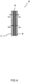
- a bipolar membrane is schematically illustrated in Figure 4 .
- the bipolar membrane (6) typically comprises an anion exchange layer (AEL) (7), a cation exchange layer (CEL) (8) and an interface layer (9).
- Cation exchange layers are typically permeable to cationic species and anion exchange layers are typically permeable to anions.
- the interface layer can generally be considered a bipolar junctional and forms the interface between the CEL and AEL. Different morphologies for such an interface layer may be possible as can be seen in e.g. Parnamae et al., Journal of Membrane Science, 617, 2021, 118538 .
- Charged species can therefore typically not be transported through all layers of bipolar membrane, however neutral species may be transported through the layers.
- the anion exchange layer faces the cathodic compartment.
- the bipolar membrane is accordingly preferably operated under forward-bias mode.
- the electrochemical cell is a two-compartment electrochemical flow cell.
- the to be treated liquid i.e. the CO 2 -lean solvent and/or the CO 2 -rich solvent
- the anodic compartment may comprise any conventional electrolyte.
- the to be treated liquid is provided in the cathodic compartment (2).
- a potential difference can be applied between the cathode and a reference electrode. Alternatively, a current can be applied.
- the method may accordingly be run galvanostatically or potentiostatically.
- a reduction potential may be applied to the cathode (3). Due to the potential at the cathode and anode (5), water may split at both the anode and cathode into H + and OH - , respectively. Water splitting at the cathode may however be preferably minimized, as this reaction may compete with the reduction of the metal ions. Accordingly, due to the bipolar membrane only a positively or negatively charged species may permeate through the exchange layers.
- the hydroxyl anions may permeate through the anionic exchange layer but are typically blocked by the cation exchange layer.
- H + may permeate through the cation exchange layer and are typically blocked by the anion exchange layer. Both ions typically meet in the interface layer.
- the hydroxyl anions and protons may recombine and the neutral water molecules may permeate back to the anodic and/or cathodic compartments through the exchange layers.
- the preferred bipolar membrane configuration may beneficially assist in resisting a pH change in the compartments as protons generated in the anodic compartment will consume the hydroxyl anions present in the cathodic compartment in the membrane interfacial layer. Further, due to the presence of the preferred bipolar membrane positively charged amines and carbamate ions are typically prevented to transport to the anodic compartment. Accordingly, oxidation of the amines is typically minimized or prevented resulting in less degradation and solvent loss. Additionally, the bipolar membrane may block metal cations to permeate through the membrane to the anodic compartment.
- the metal cations are typically reduced.
- the metal cations may be reduced to e.g. its elemental state, hydroxide, oxide and/or oxide hydroxide.
- Fe(II) may accept two electrons from the cathode and form a metal deposit of elemental iron.
- the Fe(II) may form a metal deposit of iron hydroxide, iron oxide or iron oxide hydroxide.
- the metal deposit may comprise metallic metal, metal oxide, metal oxide hydroxide and/or metal hydroxides.
- the metal deposit may be removed from the electrochemical cell for instance by filtration and/or electrochemical regeneration of the electrodes. Filtration may for instance be used in case the metal deposit is not too strongly adhered to the cathode but present as e.g. a precipitate, while for a more strongly adhered metal deposit to the cathode the metal deposit is typically removed by electrochemical regeneration of the electrodes.
- the metal is typically removed from the CO 2 -capture plant and thus tends to break the autocatalytic solvent degradation cycle.
- the cathode may also be replaced and/or removed, cleaned or regenerated (e.g. scraping and/or electrochemical treatment) and placed back.
- the cathode may comprise any suitable material including for example carbon and/or metals such as titanium, nickel, and/or iron.
- the cathode comprises graphite.
- Graphite electrodes are preferred as they are typically cheap.
- the electrode surface area may be amended to allow for a more optimal metal ion removal.
- the metal-lean fraction typically comprises the solvent that can be reused in the absorber of the CO 2 capture system.
- the metal-lean fraction may accordingly be less corrosive and an increased lifetime of the industrial equipment as well as the solvent may be achieved. Accordingly, it is preferred that the metal-lean fraction is fed to the absorber.
- a schematic overview is illustrated in Figure 2 .
- the method is a continuous method as this typically allows for the CO 2 capture process to remain active. If the method is employed continuously, the anolyte may require occasional or continuous refreshing.
- the invention is further related to a method for at least partially removing transition metal ions from a solution.
- the method comprises electroreduction of the metal ions in a two-compartment electrochemical cell comprising a bipolar membrane (6).
- the bipolar membrane separates a cathodic compartment (2) from an anodic compartment (4).
- the anion exchange layer faces the cathodic compartment.
- the invention is related to a system (100) for the method according to the present invention.
- the system comprises an absorber (101) comprising a feed fluid inlet (102) and CO 2 -rich solvent outlet (103).
- the absorber typically comprises an amine-based capture solvent, which can react with CO 2 ( vide supra ).
- the system further comprises a regenerator (104) comprising a CO 2 -rich solvent inlet (105) and a CO 2 -lean solvent outlet (106).
- the system comprises an electrochemical cell (1) comprising a metal-rich fraction inlet (108) and a metal-lean fraction outlet (109).
- the CO 2 -rich solvent outlet (103) is in fluid connection with the CO 2 -rich solvent inlet (105) and in fluid connection with the metal-rich fraction inlet (108).
- the metal-lean fraction outlet (109) is in fluid connection with the feed fluid inlet (102).
- the metal-lean fraction obtained from the electroreduction can thus be fed ( e.g. recycled) to the absorber.
- the CO 2 -lean solvent outlet (106) is in fluid connection with the feed fluid inlet (102).
- Figure 5 accordingly illustrates that the metal removal may be employed for a part of the CO 2 -rich solvent stream.
- the metal-lean fraction outlet (109) may also be in fluid connection with the CO 2 -rich liquid inlet (105).
- FIG. 6 An alternative embodiment is illustrated in Figure 6 , herein the CO 2 -lean solvent outlet (106) is in fluid connection with the feed fluid inlet (102).
- the CO 2 -rich solvent outlet (103) is in fluid connection with the metal-rich fraction inlet (108).
- the metal-lean fraction may be lead from the metal-lean fraction outlet (109) to the CO 2 -rich solvent inlet (105). Accordingly, Figure 6 illustrates that all of the CO 2 -rich solvent may be subjected to electroreduction.
- Figure 7 illustrates yet another alternative embodiment.
- the CO 2 -rich solvent outlet (103) is in fluid connection with the CO 2 -rich solvent inlet (105) and in fluid connection with the metal-rich fraction inlet (108).
- the CO 2 -lean solvent outlet (106) is in fluid connection with the feed fluid inlet (102) and with the metal-rich fraction inlet (108).
- the metal-lean fraction outlet (109) is in fluid connection with the feed fluid inlet (102).
- Figure 7 accordingly illustrates an embodiment wherein at least part of the CO 2 -rich solvent and at least part of the CO 2 -lean aqueous solvent may be subjected to the electroreduction. It may be appreciated that the metal-lean fraction outlet (109) may also be in fluid connection with the CO 2 -rich liquid inlet (105).
- Figure 8 illustrates another alternative embodiment wherein the CO 2 -rich solvent outlet (103) is in fluid connection with the CO 2 -rich solvent inlet (105).
- the CO 2 -lean solvent outlet (106) is in fluid connection with the feed fluid inlet (102) and with the metal-rich fraction inlet (108).
- the metal-lean fraction outlet (109) is in fluid connection with the feed fluid inlet (102).
- Figure 8 illustrates that at least part of the CO 2 -lean solvent is subjected to electroreduction. It may be appreciated that the metal-lean fraction outlet (109) may also be in fluid connection with the CO 2 -rich liquid inlet (105).
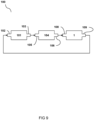
- the electrochemical cell may be placed between the regenerator and the absorber as for instance illustrated in Figure 9 .
- the CO 2 -rich solvent outlet (103) is in fluid connection with the CO 2 -rich solvent inlet (105).
- the CO 2 -lean solvent outlet (106) is in fluid connection with the metal-rich fraction inlet (108).
- the metal-lean fraction outlet (109) is in fluid connection with the feed fluid inlet (102).
- all of the CO 2 -lean solvent is subjected to electroreduction to allow for optimal metal removal and optimal recyclability.
- FIG. 10 A schematic overview of a suitable system is illustrated in Figure 10 .
- a heat exchanger (21) and a heater (23).
- the CO 2 -rich gas stream (14) may be further led to a condenser (24) to obtain a CO 2 gas stream (17).
- the electrochemical cell (1) is placed such that at least part of the CO 2 -rich solvent stream is subjected to electroreduction.
- the electrochemical cell for the method according to the present invention may be located at any place in the solvent loop of a CO 2 capture system, to allow for in-situ metal removal.
- Part of the liquids may for instance be tapped or bypassed to be subjected to electroreduction.
- the metal ions may be removed from these liquids allowing for a sufficient purification to continue the process with minimal corrosion and degradation.
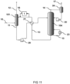
- FIG. 11 A schematic overview of a preferred system is illustrated in Figure 11 . Similarly to Figure 10 , several pumps (20, 22) a heat exchanger (21) and a heater (23) are shown. It further illustrates that the electrochemical cell is preferably placed such that at least part of the CO 2 -lean solvent stream (e.g. a slip stream) is subjected to electroreduction.
- the CO 2 -lean solvent stream e.g. a slip stream
- the invention may further be illustrated by the following nonlimiting examples.
- Figure 12 illustrates the concentration of Fe over time. At a potential of -1.3V the iron concentration is reduced from roughly 31 to 24 ppm in 5 hours.
- Example 2 electrode surface area
- the results are illustrated in Figure 13 .
- the iron concentration is reduced in three hours from roughly 75 to 60 ppm in the first cell.
- the iron concentration is reduced from approximately 35 to 30 ppm in three hours.
- the cathode was a polished graphite cathode plate with a surface area of 10cm 2 and the anode was a Pt anode plate.
- the iron concentration over time is illustrated in Figure 14 . As illustrated after roughly 21 hours the iron concentration is reduced from approximately 15 to 0.1 ppm in the second cell. After approximately 22 hours the iron concentration in the first cell is reduced from roughly 35 to 3 ppm.
Landscapes
- Chemical & Material Sciences (AREA)
- Engineering & Computer Science (AREA)
- Chemical Kinetics & Catalysis (AREA)
- Analytical Chemistry (AREA)
- General Chemical & Material Sciences (AREA)
- Oil, Petroleum & Natural Gas (AREA)
- Health & Medical Sciences (AREA)
- Environmental & Geological Engineering (AREA)
- Water Supply & Treatment (AREA)
- Biomedical Technology (AREA)
- Urology & Nephrology (AREA)
- Electrochemistry (AREA)
- Life Sciences & Earth Sciences (AREA)
- Sustainable Development (AREA)
- Water Treatment By Electricity Or Magnetism (AREA)
- Electrolytic Production Of Non-Metals, Compounds, Apparatuses Therefor (AREA)
- Gas Separation By Absorption (AREA)
Abstract
The invention is in the field of CO2 capture. In particular the invention relates to a method for capturing CO2 from a CO2-containing feed gas stream, wherein the method comprises at least partially removing dissolved transition metal ions by electroreduction. The invention further relates to a system for the method.
Description
- The invention is in the field of CO2 capture. In particular the invention relates to a method to remove metal ions from a solvent from CO2 capture processes, and a system for the method.
- It is widely acknowledged that it is desirable to minimize carbon dioxide emission and move towards a sustainable economy. A method to minimize emission is to capture and optionally regenerate the carbon dioxide. Conventional CO2 capture include processes as described in
US1783901 and for absorption based technologies the carbon dioxide containing gas (e.g. a flue gas) is fed to an absorber wherein it is contacted with a solvent. The solvent are typically amine-based aqueous solvents, such as alkanolamines. The CO2 reacts with the solvent to form i.a. carbamate and/or carbonate and/or bicarbonate ions and protonated alkanolamines, and a CO2-lean gas which leaves the absorber. The CO2-rich stream can be fed to a regenerator (e.g. stripper), wherein typically a reboiler is present at the bottom to remove the CO2 from the solvent. Typically, the highest temperature in the regenerator is around 120°C. - The high temperature in the stripper can cause degradation of the amine (thermal degradation). Moreover, the feed gas typically comprises oxygen and the presence of oxygen cause solvent degradation (e.g. through an oxidative degradation pathway). As described i.a. by H. Liu & G. Rochelle (Oxidative degradation of amine solvents for CO2 capture, Master Thesis UT Austin (2015)), the oxidative degradation pathway is the main degradation mechanism and it is responsible for about 70% of total amine losses. This may be severe and a wide variety of volatile products (e.g. ammonia) and heat-stable salts can be formed. Further, the degradation products can be corrosive to the material of the CO2 capture plant (i.a. absorber, regenerator, pipes), which typically comprise stainless steel. The corrosion may be monitored by the amount of metal that originate from the material of the CO2 capture plant. The particular metals and what metal may be predominantly present may for instance depend on i.a. the type of stainless steel and/or the degree of stainless steel. Typically, iron, chromium and nickel can be found as dissolved ions in the capture solvent. The dissolved metal ions can further be considered as a catalyst for the oxidative degradation, which will subsequently lead to more degradation and that will lead to more corrosivity of the solvent. This cycle can be considered as an autocatalytic process.
- To recover the solvent quality by removing impurities, reclaiming processes can be employed. Reclaiming processes are typically operated batch-wise and may be costly.
- An example of a solvent reclaiming process is thermal reclaiming, wherein heat is used to distill a part of the non-degraded solvent (e.g. amines) from the solution. However, more solvent may degrade during the reclaiming and thermal reclaiming is typically paired with significant losses of the non-reclaimed solvent. Additionally, thermal reclaiming is energy intensive and typically results in a hazardous waste stream comprising impurities, degradation products and salts. A further drawback is the limited throughput, roughly 1-2% of the total solvent flow can be subjected to thermal reclaiming.
- Another method comprises ion-exchange resins, which are often used to remove charged contaminants. The principle is based on the use of cation exchange resins to replace cationic species with protons and anion exchange resins to replace anionic species with hydroxyl ions. An example hereof is disclosed in
US4795565 . Herein heat stable salts are removed from ethanolamine gas purification process units using ion-exchange resins. A further example, in particular for anion exchange resins, is disclosed inEP0430432 . Herein an alkanolamine solution containing heat stable alkanolamine salts of acidic anions is contacted with an anion exchange resin to remove the acidic anions. Small amounts of metal cations may also be captured by the resin. However, ion-exchange resins may require aggressive regeneration cycles, typically leading to large amounts of strong acids and bases that have to be recycled or disposed of. Accordingly, the use of ion-exchange resins may be paired with increasing complexity of the solvent and waste management. Additionally, there is typically a risk that some of the carbamate ions and protonated alkanolamines are captured by the resins. - A further example is electrodialysis. Electrodialysis can be employed to remove charged species from aqueous solvents. Herein a stack of alternating cation exchange membranes and anion exchange membranes are typically used to drive charged species through the selectively permeable membranes under an applied potential difference. A drawback of using electrodialysis is membrane fouling which increases ohmic resistance and accordingly reduces efficiency. Additionally, the carbamate ions and protonated amines may permeate through the membranes leading to a loss of solvent. This may be particularly unbeneficial at high CO2 loading as a high concentration of carbamate and protonated amines may be present.
- A need however remains on the removal of the metal ions as these seem to be a major contributor to solvent degradation. One way to remove metal from an amine-based solvent from a CO2 capture process is disclosed in
US2015/0258497 . Herein a metal ion chelator is used to form a coordination complex with the metal ion. However, the metal ion chelator is in the form of a resin which requires the use of chemical eluents for the regeneration of the chelator and accordingly creates another waste stream or, alternatively, requires frequent refreshing of the chelator. Additionally, with increasing cationic amine species the selectivity of the chelator may decrease. - Activated carbon is also a proposed solution to remove degradation products from CO2 capture solvents. The throughput is variable, from approximately 1-2% up to 10-20% of the total solvent flow. In a campaign at a large pilot plant operating with monoethanolamine, no effect of the active carbon on the iron content was observed (Morken et al. International Journal of Greenhouse Gas Control (2019) Vol. 82 175-183). Further, the activated carbon typically needs to be replaced or regenerated. As the activated carbon may absorb degradation compounds safety issues are typically associated with replacing the activated carbon.
- It is an object of the present inventors to provide an improved method for removing transition metal ions (herein also referred to as metal ions) from CO2 capture liquids that overcomes at least part of the above-mentioned drawbacks. The present inventors surprisingly found that such a method can be obtained by using electroreduction of the metal ions.
-
Figure 1 illustrates a schematic flow-chart of a preferred method according to the present invention. -
Figure 2 illustrates a schematic flow-chart of a preferred method according to the present invention. -
Figure 3 illustrates an electrochemical cell suitable for the method according to the present invention. -
Figure 4 illustrates a bipolar membrane suitable for the method according to the present invention. -
Figure 5-10 illustrate schematic overviews of alternative embodiments of a system according to the present invention. -
Figure 11 illustrates a schematic overview of a preferred system according to the present invention. -
Figure 12 illustrates the iron concentration over time at different cell potentials. -
Figure 13 illustrates the iron concentration over time for different starting concentrations.. -
Figure 14 illustrates the iron concentration over time for different starting concentrations and long-term operation (> 20h). - Thus, in a first aspect the present invention is directed to a method for CO2 capture from a CO2-containing feed gas stream (10). The method is schematically illustrated as flow-chart in
Figure 1 . The method accordingly comprises providing the feed gas stream in an absorber (101) comprising an solvent to absorb CO2 in the solvent to obtain a CO2-rich solvent stream (11) and a CO2-lean gas stream (12). The solvent typically reacts with the CO2 present in the feed gas. The CO2-rich solvent stream can be led to a regenerator (104). In the regenerator the reaction of the solvent with CO2 is typically reversed to obtain a CO2-lean solvent stream (13) and a CO2-rich gas stream (14). Further illustrated inFigure 1 , the CO2-lean solvent stream is preferably led back to the absorber. Generally, oxygen is present in the feed gas which may cause solvent degradation. The solvent degradation products can be corrosive. This can lead to the generation of metal ions into solution. The origin of the metal ions can be from the metallic parts of the capture plant (e.g. absorber, heat exchangers, stripper, piping, packing material). Accordingly, the CO2-rich solvent stream and/or the CO2-lean solvent stream comprise dissolved transition metal ions. The method further comprises at least partially removing these dissolved transition metal ions. Removal of the dissolved metal ions comprises electroreduction of the dissolved transition metal ions in an electrochemical cell (1) to obtain a metal deposit (15). - The method may be performed at ambient temperature and pressure, but as well at temperature and pressure conditions present in the capture plant. The method according to the present invention may allow for a reduced waste management, avoid fast degradation of the solvents and increase the lifetime of both solvent and industrial equipment.
- The CO2-containing feed gas stream may be any feed gas that comprises carbon dioxide. Examples include, but are not limited to flue gasses from industrial processes, air, exhaust gasses and natural gas. The feed gasses may further comprise other gasses such as molecular oxygen and/or molecular nitrogen.
- The feed gas enters an absorber in which during use a solvent is provided and reacts with the carbon dioxide to absorb the CO2. Such solvents typically comprise amine-based solvents. Preferably the solvent comprises a CO2 capture solvent (i.e. a liquid that reacts with the CO2), herein also referred to as capture solvent. Examples of suitable CO2 capture solvent include amine-based liquids such as piperazine, glycol-based liquids and/or liquids comprising an amino-acid. More specific examples are for instance alkanolamines, such as monoethanolamine (MEA), aminomethyl propanol (AMP), methyl diethanolamine (MDEA)and combinations thereof such as a blend of 27 wt% AMP and 13 wt% piperazine (CESAR1). The CO2 reacts with such solvents to produce i.a. charged species, in particular carbamate, bicarbonate and carbonate ions and protonated amines. Accordingly, the solvent streams typically comprises these solvents. The solvent may further comprise water but it may also be anhydrous. The solvent may for instance be an aqueous solution of MEA.
- It may be preferred to subject the CO2-lean solvent stream to electroreduction. Considering MEA as capture solvent, for example, the CO2-lean loading is preferably around 0.2mol CO2/mol amine.
- The CO2 plant, in particular the absorber, regenerator and/or the pipes, typically comprise stainless steel housing. Accordingly, the corrosion due to the degradation products typically result in the release of transition metal ions in the liquid. These transition metal are typically iron cations, nickel cations, chromium cations, cobalt cations and/or manganese cations. Cations are herein used to refer to any individual or combination of oxidation states of the metal. For instance iron cations refer to Fe(II), Fe(III), Fe(IV) and/or Fe(VI). Similarly, nickel cations may refer to Ni(I), Ni(II), Ni(III) and/or Ni(IV). Chromium cations is used for Cr(I), Cr(II), Cr(III), Cr(IV), Cr(V) and/or Cr(VI). Cobalt cations may refer to Co(I), Co(I), Co(III), Co(IV) and/or Co(V). Manganese cations may be Mn(I), Mn(II), Mn(III), Mn(IV), Mn(V), Mn(VI) and/or Mn(VII). Generally, in the solvent the metal ions include Fe(II), Fe(III), Ni(II), Ni(III), Cr(III), Cr(VI), Co (II), Co(III) and/or Mn(II). Typically, the metal ions are iron cations, nickel cations and/or chromium cations, mainly iron cations. Iron cations are typically present in higher concentrations and accordingly, the transition metal cations are typically Fe(II) and/or Fe(III). The Roman numerals in the brackets indicate the oxidative state, e.g. Fe(II) is Fe2+.
- Typically, the transition metal concentration in the CO2-rich solvent stream and/or the CO2-lean solvent stream depends on the nature of the feed gas and solvent used. For a stable operation with minimal corrosion and degradation, a metal concentration of less than 5 mg/kg is typically preferred. If no reclaiming process is used, the iron concentration increases over time, typically reaching values much higher than 5 mg/kg, up to 50-100 mg/kg, a point at which operation of the plant needs to be stopped. Accordingly, the method of the present application can be applied to a transition metal concentration in the CO2-rich solvent stream and/or the CO2-lean solvent stream of at least 5 mg/kg, preferably at least 15 mg/kg, such as at least 20 mg/kg..
- The dissolved metal ions are at least partially removed through electroreduction of the dissolved transition metal ions in an electrochemical cell (1) to obtain a metal deposit. Electroreduction is generally based on the application of an electric current or a reductive potential to discharge cationic species in an electrolyte via an electron-accepting step at the cathode. The electroreduction is carried out in an electrochemical cell. The cells typically comprise a cathode and an anode that are separated by an electrolyte and/or membrane. Additionally, as conventional in the art, the cell may comprise one or more reference electrodes that may be used to control the cathode and/or anode potential. The process can be run galvanostatically (i.e. by applying a current) or potentiostatically (i.e. by applying a potential on either the cathode, anode or cell).
- During electroreduction, a reductive potential or a reductive current is typically applied to the cathode. The reductive potential or current may be specifically chosen such that it allows for the selective reduction of the targeted species (i.e. the metal ion(s)). Accordingly, the reductive potential typically varies depending on the conditions such as the cathode material, the cation(s) to be reduced and the electrolyte composition. Generally, the reductive potential applied at the cathode is preferably between -3 and 3V vs Ag/AgCl, preferably between 0 and -3V vs Ag/AgCl. As an example, for the reduction of Fe(II) to Fe(0) on a graphite electrode in a 30% MEA aqueous solution with Ag/AgCl as reference electrode, the reductive potential applied may be between -0.8 and -1.5V, such as between -1.0 and -1.4V. This potential is particularly favorable for reduction of iron cations. Further, the reduction potential may be amended over time, to for instance first reduce a first metal followed by the reduction of a second metal. Alternatively or additionally, multiple electrochemical cells may be employed to selectively reduce the individual metal ions. As the metals may be similar (i.e. close in the period table) the metals may have an overlapping reduction potential that may result in the reduction of more than one metal ion at a particular applied reduction potential.
- In order to minimize or prevent any losses of oxidizable species in the solvent, such as carbamate ions, amines or protonated amines, the electrochemical cell is preferably a two-compartment electrochemical cell. However, a one-compartment cell comprising a cathode and an anode may suffice for a capture solvent that is stable. A suitable two-compartment electrochemical cell is illustrated in
Figure 3 . The two-compartment electrochemical cell preferably comprises a cathodic compartment (2) comprising a cathode (3) and an anodic compartment (4) comprising an anode (5). Further, the electrochemical cell preferably comprises a bipolar membrane (6) that separates the anodic compartment and the cathodic compartment. The reduced losses of charged species may contribute to an increased solvent stability, such as increased lifetime and electrochemical stability of the solvent. - A bipolar membrane is schematically illustrated in
Figure 4 . The bipolar membrane (6) typically comprises an anion exchange layer (AEL) (7), a cation exchange layer (CEL) (8) and an interface layer (9). Cation exchange layers are typically permeable to cationic species and anion exchange layers are typically permeable to anions. The interface layer can generally be considered a bipolar junctional and forms the interface between the CEL and AEL. Different morphologies for such an interface layer may be possible as can be seen in e.g. Parnamae et al., Journal of Membrane Science, 617, 2021, 118538. Charged species can therefore typically not be transported through all layers of bipolar membrane, however neutral species may be transported through the layers. Typically, the anion exchange layer faces the cathodic compartment. The bipolar membrane is accordingly preferably operated under forward-bias mode. - It is even more preferred that the electrochemical cell is a two-compartment electrochemical flow cell. In such a flow cell, the to be treated liquid (i.e. the CO2-lean solvent and/or the CO2-rich solvent) is typically fed to and flows through the cathodic compartment. The anodic compartment may comprise any conventional electrolyte.
- In the two-compartment flow cell as illustrated in
Figure 3 the to be treated liquid is provided in the cathodic compartment (2). A potential difference can be applied between the cathode and a reference electrode. Alternatively, a current can be applied. The method may accordingly be run galvanostatically or potentiostatically. A reduction potential may be applied to the cathode (3). Due to the potential at the cathode and anode (5), water may split at both the anode and cathode into H+ and OH-, respectively. Water splitting at the cathode may however be preferably minimized, as this reaction may compete with the reduction of the metal ions. Accordingly, due to the bipolar membrane only a positively or negatively charged species may permeate through the exchange layers. In other words, from the cathodic compartment only the hydroxyl anions may permeate through the anionic exchange layer but are typically blocked by the cation exchange layer. Similarly, from the anodic compartment only H+ may permeate through the cation exchange layer and are typically blocked by the anion exchange layer. Both ions typically meet in the interface layer. Here, the hydroxyl anions and protons may recombine and the neutral water molecules may permeate back to the anodic and/or cathodic compartments through the exchange layers. - The preferred bipolar membrane configuration may beneficially assist in resisting a pH change in the compartments as protons generated in the anodic compartment will consume the hydroxyl anions present in the cathodic compartment in the membrane interfacial layer. Further, due to the presence of the preferred bipolar membrane positively charged amines and carbamate ions are typically prevented to transport to the anodic compartment. Accordingly, oxidation of the amines is typically minimized or prevented resulting in less degradation and solvent loss. Additionally, the bipolar membrane may block metal cations to permeate through the membrane to the anodic compartment.
- By applying the reduction potential or a current to the cathode, the metal cations are typically reduced. The metal cations may be reduced to e.g. its elemental state, hydroxide, oxide and/or oxide hydroxide. For instance, Fe(II) may accept two electrons from the cathode and form a metal deposit of elemental iron. Alternatively or additionally, the Fe(II) may form a metal deposit of iron hydroxide, iron oxide or iron oxide hydroxide. Without wishing to be bound by theory the present inventors believe that the reduced metal at the cathode may re-oxidize after the reductive potential is removed. Accordingly, the metal deposit may comprise metallic metal, metal oxide, metal oxide hydroxide and/or metal hydroxides.
- Dependent on the metal deposit, the metal deposit may be removed from the electrochemical cell for instance by filtration and/or electrochemical regeneration of the electrodes. Filtration may for instance be used in case the metal deposit is not too strongly adhered to the cathode but present as e.g. a precipitate, while for a more strongly adhered metal deposit to the cathode the metal deposit is typically removed by electrochemical regeneration of the electrodes. The metal is typically removed from the CO2-capture plant and thus tends to break the autocatalytic solvent degradation cycle. As the metal deposit typically forms on the cathode, the cathode may also be replaced and/or removed, cleaned or regenerated (e.g. scraping and/or electrochemical treatment) and placed back. The cathode may comprise any suitable material including for example carbon and/or metals such as titanium, nickel, and/or iron. Preferably, the cathode comprises graphite. Graphite electrodes are preferred as they are typically cheap. The electrode surface area may be amended to allow for a more optimal metal ion removal.
- Further, as the transition metal ions are deposited a metal-lean fraction (16) remains. The metal-lean fraction typically comprises the solvent that can be reused in the absorber of the CO2 capture system. The metal-lean fraction may accordingly be less corrosive and an increased lifetime of the industrial equipment as well as the solvent may be achieved. Accordingly, it is preferred that the metal-lean fraction is fed to the absorber. A schematic overview is illustrated in
Figure 2 . - In a preferred embodiment, the method is a continuous method as this typically allows for the CO2 capture process to remain active. If the method is employed continuously, the anolyte may require occasional or continuous refreshing.
- The invention is further related to a method for at least partially removing transition metal ions from a solution. The method comprises electroreduction of the metal ions in a two-compartment electrochemical cell comprising a bipolar membrane (6). The bipolar membrane separates a cathodic compartment (2) from an anodic compartment (4). Preferably wherein the anion exchange layer faces the cathodic compartment.
- In a further aspect, the invention is related to a system (100) for the method according to the present invention. Several embodiments are illustrated in
Figures 5-10 . The system comprises an absorber (101) comprising a feed fluid inlet (102) and CO2-rich solvent outlet (103). During use the absorber typically comprises an amine-based capture solvent, which can react with CO2 (vide supra). The system further comprises a regenerator (104) comprising a CO2-rich solvent inlet (105) and a CO2-lean solvent outlet (106). Additionally, the system comprises an electrochemical cell (1) comprising a metal-rich fraction inlet (108) and a metal-lean fraction outlet (109). As can be seen inFigure 5 , the CO2-rich solvent outlet (103) is in fluid connection with the CO2-rich solvent inlet (105) and in fluid connection with the metal-rich fraction inlet (108). The metal-lean fraction outlet (109) is in fluid connection with the feed fluid inlet (102). The metal-lean fraction obtained from the electroreduction can thus be fed (e.g. recycled) to the absorber. Additionally, inFigure 5 it is further illustrated that the CO2-lean solvent outlet (106) is in fluid connection with the feed fluid inlet (102).Figure 5 accordingly illustrates that the metal removal may be employed for a part of the CO2-rich solvent stream. It may be appreciated that the metal-lean fraction outlet (109) may also be in fluid connection with the CO2-rich liquid inlet (105). - An alternative embodiment is illustrated in
Figure 6 , herein the CO2-lean solvent outlet (106) is in fluid connection with the feed fluid inlet (102). The CO2-rich solvent outlet (103) is in fluid connection with the metal-rich fraction inlet (108). The metal-lean fraction may be lead from the metal-lean fraction outlet (109) to the CO2-rich solvent inlet (105). Accordingly,Figure 6 illustrates that all of the CO2-rich solvent may be subjected to electroreduction. -
Figure 7 illustrates yet another alternative embodiment. Herein, the CO2-rich solvent outlet (103) is in fluid connection with the CO2-rich solvent inlet (105) and in fluid connection with the metal-rich fraction inlet (108). The CO2-lean solvent outlet (106) is in fluid connection with the feed fluid inlet (102) and with the metal-rich fraction inlet (108). The metal-lean fraction outlet (109) is in fluid connection with the feed fluid inlet (102).Figure 7 accordingly illustrates an embodiment wherein at least part of the CO2-rich solvent and at least part of the CO2-lean aqueous solvent may be subjected to the electroreduction. It may be appreciated that the metal-lean fraction outlet (109) may also be in fluid connection with the CO2-rich liquid inlet (105). -
Figure 8 illustrates another alternative embodiment wherein the CO2-rich solvent outlet (103) is in fluid connection with the CO2-rich solvent inlet (105). The CO2-lean solvent outlet (106) is in fluid connection with the feed fluid inlet (102) and with the metal-rich fraction inlet (108). The metal-lean fraction outlet (109) is in fluid connection with the feed fluid inlet (102).Figure 8 illustrates that at least part of the CO2-lean solvent is subjected to electroreduction. It may be appreciated that the metal-lean fraction outlet (109) may also be in fluid connection with the CO2-rich liquid inlet (105). - In another alternative embodiment, the electrochemical cell may be placed between the regenerator and the absorber as for instance illustrated in
Figure 9 . Herein the CO2-rich solvent outlet (103) is in fluid connection with the CO2-rich solvent inlet (105). The CO2-lean solvent outlet (106) is in fluid connection with the metal-rich fraction inlet (108). The metal-lean fraction outlet (109) is in fluid connection with the feed fluid inlet (102). In this preferred embodiment, all of the CO2-lean solvent is subjected to electroreduction to allow for optimal metal removal and optimal recyclability. - A schematic overview of a suitable system is illustrated in
Figure 10 . Herein several pumps (20, 22) are shown, a heat exchanger (21) and a heater (23). Further, it illustrates that the CO2-rich gas stream (14) may be further led to a condenser (24) to obtain a CO2 gas stream (17). The electrochemical cell (1) is placed such that at least part of the CO2-rich solvent stream is subjected to electroreduction. - Accordingly, the electrochemical cell for the method according to the present invention may be located at any place in the solvent loop of a CO2 capture system, to allow for in-situ metal removal. Part of the liquids may for instance be tapped or bypassed to be subjected to electroreduction. As at least part of the liquids is subjected to electroreduction, the metal ions may be removed from these liquids allowing for a sufficient purification to continue the process with minimal corrosion and degradation.
- A schematic overview of a preferred system is illustrated in
Figure 11 . Similarly toFigure 10 , several pumps (20, 22) a heat exchanger (21) and a heater (23) are shown. It further illustrates that the electrochemical cell is preferably placed such that at least part of the CO2-lean solvent stream (e.g. a slip stream) is subjected to electroreduction. - For the purpose of clarity and a concise description features are described herein as part of the same or separate embodiments, however, it will be appreciated that the scope of the invention may include embodiments having combinations of all or some of the features described.
- The invention may further be illustrated by the following nonlimiting examples.
- Two batch experiments were performed using an aqueous MEA solution with approximately 30 ppm Fe2+ concentration and a CO2 loading of approximately 0.48 mol CO2/mol MEA (typical rich loading). In a first two-compartment cell a potential of -1.3V was applied. In the second two-compartment cell a potential of -0.6V was applied. Graphite cathodes of 1cm2 surface area were used in both cells.
-
Figure 12 illustrates the concentration of Fe over time. At a potential of -1.3V the iron concentration is reduced from roughly 31 to 24 ppm in 5 hours. - Two experiments were carried out in a two-compartment electrochemical flow cell with 10cm2 cathode surface area to determine if the increase in cathode surface area from 1cm2 (Example 1) to 10cm2 has an effect. Both experiments used aqueous MEA solutions. A first solution comprised approximately 75 ppm Fe2+, the second solution comprised approximately 35 ppm Fe2+. Both solutions had a CO2 loading of roughly 0.23 mol CO2/mol MEA (typical lean loading). The applied potential in both two-compartment cells was -1.3 V.
- The results are illustrated in
Figure 13 . The iron concentration is reduced in three hours from roughly 75 to 60 ppm in the first cell. In the second cell the iron concentration is reduced from approximately 35 to 30 ppm in three hours. - Two batch experiments were carried out using aqueous MEA solutions in a two-compartment electrochemical flow cell. The first solution had an Fe2+ concentration of approximately 35 ppm and the second solution approximately 15 ppm. Both solutions had a CO2 loading of roughly 0.25 mol CO2/mol MEA. The applied potential in both cells was -1.3V. The cathode was a polished graphite cathode plate with a surface area of 10cm2 and the anode was a Pt anode plate.
- The iron concentration over time is illustrated in
Figure 14 . As illustrated after roughly 21 hours the iron concentration is reduced from approximately 15 to 0.1 ppm in the second cell. After approximately 22 hours the iron concentration in the first cell is reduced from roughly 35 to 3 ppm.
Claims (15)
- A method for capturing CO2 from a CO2-containing feed gas stream, wherein the method comprises:- providing the feed gas stream (10) in an absorber (101) comprising a solvent to absorb CO2 in the solvent to obtain a CO2-rich solvent stream (11) and a CO2-lean gas stream (12);- leading the CO2-rich solvent stream to a regenerator (104) to obtain a CO2-lean solvent stream (13) and a CO2-rich gas stream (14);wherein the CO2-rich solvent stream and/or the CO2-lean solvent stream comprise dissolved transition metal ions;wherein the method further comprises at least partially removing the dissolved transition metal ions from the CO2-rich solvent stream and/or the CO2-lean solvent stream comprising electroreduction and deposition of the dissolved transition metal ions in an electrochemical cell (1) to obtain a metal deposit.
- Method according to the previous claim, wherein the CO2-rich solvent stream and the CO2-lean solvent stream comprises a CO2 capture solvent, preferably an amine-based liquid such as piperazine, a glycol-based liquid and/or a liquid comprising an amino-acid, more preferably an alkanolamine, most preferably aminomethyl propanol (AMP), methyl diethanolamine (MDEA), monoethanolamine (MEA) or combinations thereof such as a blend of 27 wt% AMP and 13 wt% piperazine (CESAR1).
- Method according to any the previous claims, wherein the transition metal ions are selected from the group consisting of: iron cations, nickel cations, chromium cations, cobalt cations, manganese cations and a combination thereof, preferably wherein the transition metal ions are selected from the group consisting of: iron cations, nickel cations, chromium cations and a combination thereof, more preferably the transition metal ions are iron cations.
- Method according to any of the previous claims, wherein the electrochemical cell (1) is a one-compartment electrochemical cell comprising a cathode (3) and an anode (5).
- Method according to any of the previous claims 1-3, wherein the electrochemical cell (1) is a two-compartment electrochemical cell comprising a cathodic compartment (2) comprising a cathode (3) and an anodic compartment (4) comprising an anode (5), preferably wherein the electrochemical cell is a two-compartment electrochemical flow cell.
- Method according to the previous claim, wherein the two-compartment electrochemical cell further comprises a bipolar membrane (6) comprising an anion exchange layer (7), a cation exchange layer (8) and an interface layer (9), wherein the bipolar membrane separates the anodic compartment and the cathodic compartment.
- Method according to the previous claim, wherein the anion exchange layer (7) of the bipolar membrane (6) faces the cathodic compartment.
- Method according to any of the previous claims, wherein the transition metal concentration in the CO2-rich solvent stream and/or the CO2-lean solvent stream is at least 5 ppm.
- Method according to any of the previous claims, wherein the method further comprises:- feeding at least part of the CO2-rich solvent stream and/or at least part of the CO2-lean solvent stream to the electrochemical cell (1), preferably to the cathodic compartment (2) of the electrochemical cell;- applying the reductive potential to reduce the transition metal ions to obtain a metal deposit and a metal-lean fraction (15).
- Method according to the previous claim, wherein the metal-lean fraction is fed to the absorber.
- Method according to any of the previous claims, wherein the method further comprises removing the metal deposit.
- Method according to any of the previous claims, wherein the method is a continuous method.
- Method for at least partially removing transition metal ions from a solution, wherein the method comprises electroreduction of the metal ions in a two-compartment electrochemical cell comprising a bipolar membrane (6) comprising an anion exchange layer (7), a cation exchange layer (8) and an interface layer (9), wherein the bipolar membrane separates a cathodic compartment (2) from an anodic compartment (4), preferably wherein the anion exchange layer faces the cathodic compartment.
- A system (100) for capturing CO2 from a CO2-containing feed gas stream according to the method of any of the previous claims, wherein the system comprises;- an absorber (101) comprising a feed fluid inlet (102) and CO2-rich solvent outlet (103);- a regenerator (104) comprising a CO2-rich solvent inlet (105) and a CO2-lean solvent outlet (106);- an electrochemical cell (1) comprising a metal-rich fraction inlet (108) and a metal-lean fraction outlet (109),wherein the CO2-rich solvent outlet (103) is in fluid connection with the CO2-rich solvent inlet (105) and/or in fluid connection with the metal-rich fraction inlet (108);wherein the CO2-lean solvent outlet (106) is in fluid connection with the metal-rich fraction inlet (108) and/or in fluid connection with the feed fluid inlet (102);wherein the metal-lean fraction outlet (109) is in fluid connection with the feed fluid inlet (102) and/or in fluid connection with the CO2-rich solvent inlet (105).
- System according to the previous claim wherein the CO2-lean solvent outlet (106) is in fluid connection with the metal-rich fraction inlet (108), preferably wherein the CO2-lean solvent outlet (106) is in fluid connection with the metal-rich fraction inlet (108), the metal-lean fraction outlet (109) is in fluid connection with the fluid inlet (102) and the CO2-rich solvent outlet (103) is in fluid connection with the CO2-rich solvent inlet (105).
Priority Applications (4)
| Application Number | Priority Date | Filing Date | Title |
|---|---|---|---|
| EP21190802.5A EP4134152A1 (en) | 2021-08-11 | 2021-08-11 | Electrochemical metal removal |
| EP22754583.7A EP4384302A1 (en) | 2021-08-11 | 2022-08-11 | Electrochemical metal removal |
| US18/293,855 US20240325976A1 (en) | 2021-08-11 | 2022-08-11 | Electrochemical Metal Removal |
| PCT/NL2022/050466 WO2023018331A1 (en) | 2021-08-11 | 2022-08-11 | Electrochemical metal removal |
Applications Claiming Priority (1)
| Application Number | Priority Date | Filing Date | Title |
|---|---|---|---|
| EP21190802.5A EP4134152A1 (en) | 2021-08-11 | 2021-08-11 | Electrochemical metal removal |
Publications (1)
| Publication Number | Publication Date |
|---|---|
| EP4134152A1 true EP4134152A1 (en) | 2023-02-15 |
Family
ID=77300832
Family Applications (2)
| Application Number | Title | Priority Date | Filing Date |
|---|---|---|---|
| EP21190802.5A Withdrawn EP4134152A1 (en) | 2021-08-11 | 2021-08-11 | Electrochemical metal removal |
| EP22754583.7A Pending EP4384302A1 (en) | 2021-08-11 | 2022-08-11 | Electrochemical metal removal |
Family Applications After (1)
| Application Number | Title | Priority Date | Filing Date |
|---|---|---|---|
| EP22754583.7A Pending EP4384302A1 (en) | 2021-08-11 | 2022-08-11 | Electrochemical metal removal |
Country Status (3)
| Country | Link |
|---|---|
| US (1) | US20240325976A1 (en) |
| EP (2) | EP4134152A1 (en) |
| WO (1) | WO2023018331A1 (en) |
Families Citing this family (1)
| Publication number | Priority date | Publication date | Assignee | Title |
|---|---|---|---|---|
| CN119701618B (en) * | 2025-02-25 | 2025-05-09 | 中国华能集团清洁能源技术研究院有限公司 | Electrochemical carbon capture flue gas purification method and system |
Citations (7)
| Publication number | Priority date | Publication date | Assignee | Title |
|---|---|---|---|---|
| US1783901A (en) | 1930-10-07 | 1930-12-02 | Girdler Corp | Process for separating acidic gases |
| US4795565A (en) | 1987-10-28 | 1989-01-03 | Mobil Oil Corporation | Clean up of ethanolamine to improve performance and control corrosion of ethanolamine units |
| EP0430432A2 (en) | 1989-10-26 | 1991-06-05 | Conoco Inc. | Removal of heat stable anions from alkanolamine salts |
| US5622681A (en) * | 1992-01-21 | 1997-04-22 | The Dow Chemical Company | Dialysis separation of heat stable organic amine salts in an acid gas absorption process |
| US20150258497A1 (en) | 2014-03-13 | 2015-09-17 | Fluor Technologies Corporation | Removal of metals from co2 capture solvents |
| US20150290576A1 (en) * | 2012-11-16 | 2015-10-15 | Asahi Kasei Kabushiki Kaisha | Bipolar electrodialyzer and purification method for amine fluid using same |
| US20210047743A1 (en) * | 2018-03-05 | 2021-02-18 | Nederlandse Organisatie Voor Toegepast-Natuurwetenschappelijk Onderzoek Tno | Method for electrochemically reducing carbon dioxide |
-
2021
- 2021-08-11 EP EP21190802.5A patent/EP4134152A1/en not_active Withdrawn
-
2022
- 2022-08-11 WO PCT/NL2022/050466 patent/WO2023018331A1/en not_active Ceased
- 2022-08-11 US US18/293,855 patent/US20240325976A1/en active Pending
- 2022-08-11 EP EP22754583.7A patent/EP4384302A1/en active Pending
Patent Citations (7)
| Publication number | Priority date | Publication date | Assignee | Title |
|---|---|---|---|---|
| US1783901A (en) | 1930-10-07 | 1930-12-02 | Girdler Corp | Process for separating acidic gases |
| US4795565A (en) | 1987-10-28 | 1989-01-03 | Mobil Oil Corporation | Clean up of ethanolamine to improve performance and control corrosion of ethanolamine units |
| EP0430432A2 (en) | 1989-10-26 | 1991-06-05 | Conoco Inc. | Removal of heat stable anions from alkanolamine salts |
| US5622681A (en) * | 1992-01-21 | 1997-04-22 | The Dow Chemical Company | Dialysis separation of heat stable organic amine salts in an acid gas absorption process |
| US20150290576A1 (en) * | 2012-11-16 | 2015-10-15 | Asahi Kasei Kabushiki Kaisha | Bipolar electrodialyzer and purification method for amine fluid using same |
| US20150258497A1 (en) | 2014-03-13 | 2015-09-17 | Fluor Technologies Corporation | Removal of metals from co2 capture solvents |
| US20210047743A1 (en) * | 2018-03-05 | 2021-02-18 | Nederlandse Organisatie Voor Toegepast-Natuurwetenschappelijk Onderzoek Tno | Method for electrochemically reducing carbon dioxide |
Non-Patent Citations (3)
| Title |
|---|
| H. LIUG. ROCHELLE: "Master Thesis UT Austin", 2015, article "Oxidative degradation of amine solvents for C0 capture" |
| MORKEN ET AL., INTERNATIONAL JOURNAL OF GREENHOUSE GAS CONTROL, vol. 82, 2019, pages 175 - 183 |
| PARNAMAE ET AL., JOURNAL OF MEMBRANE SCIENCE, vol. 617, 2021, pages 118538 |
Also Published As
| Publication number | Publication date |
|---|---|
| WO2023018331A1 (en) | 2023-02-16 |
| US20240325976A1 (en) | 2024-10-03 |
| EP4384302A1 (en) | 2024-06-19 |
Similar Documents
| Publication | Publication Date | Title |
|---|---|---|
| US6149788A (en) | Method and apparatus for preventing scaling in electrodeionization units | |
| US6294066B1 (en) | Apparatus and process for electrodialysis of salts | |
| CN117222465A (en) | Electrochemically enhanced methods for next-generation carbon dioxide capture | |
| WO2013153692A1 (en) | Method for collecting lithium | |
| EP3762522A1 (en) | Method for electrochemically reducing carbon dioxide | |
| Bazhenov et al. | Heat stable salts (HSS) removal by electrodialysis: reclaiming of MEA used in post-combustion CO2-capture | |
| EP1890970A1 (en) | Electrodialysis reversal and electrochemical wastewater treatment method of compound containing nitrogen | |
| CN112742176B (en) | Method and device for purifying and removing heat-stable salt in amine liquid | |
| WO2014120876A1 (en) | Rechargeable electrochemical cells | |
| JP2011131210A (en) | Device and method for treating nitrogen compound-containing acidic solutions | |
| US20130008858A1 (en) | Systems and Methods for Process Stream Treatment | |
| US20240325976A1 (en) | Electrochemical Metal Removal | |
| CN112742177A (en) | Method and device for purifying and removing heat stable salt in amine liquid | |
| Wang et al. | Removal of heat stable salts from degraded amine solvent by “BMED+ ED” two-stage electrodialysis unit | |
| WO2008079362A1 (en) | Systems and methods for process stream treatment | |
| WO2012139219A1 (en) | Process for purifying absorbents comprising polyethylene glycol dimethyl ethers | |
| Burns et al. | The UCARSEP® process for on-line removal of non-regenerable salts from amine units | |
| Shen et al. | Clean post-processing of 2-amino-1-propanol sulphate by bipolar membrane electrodialysis for industrial processing of 2-amino-1-propanol | |
| RU2824632C1 (en) | Method of regenerating package of ion-exchange membranes of electrodialyzer from degradation products of amine absorbent | |
| JPH08966A (en) | Purification by electrodialysis | |
| US20260015747A1 (en) | System and methods of water electrolysis | |
| EP4729660A2 (en) | System and methods of water electrolysis | |
| CN115806369B (en) | A process for desalting and dechlorinating lean amine solution | |
| CN112811687A (en) | Treatment method and treatment system for salt-containing wastewater | |
| US20250368550A1 (en) | Mitigation and recovery of degraded device efficiency in water electrolyzers caused by impurities |
Legal Events
| Date | Code | Title | Description |
|---|---|---|---|
| PUAI | Public reference made under article 153(3) epc to a published international application that has entered the european phase |
Free format text: ORIGINAL CODE: 0009012 |
|
| STAA | Information on the status of an ep patent application or granted ep patent |
Free format text: STATUS: THE APPLICATION HAS BEEN PUBLISHED |
|
| AK | Designated contracting states |
Kind code of ref document: A1 Designated state(s): AL AT BE BG CH CY CZ DE DK EE ES FI FR GB GR HR HU IE IS IT LI LT LU LV MC MK MT NL NO PL PT RO RS SE SI SK SM TR |
|
| P01 | Opt-out of the competence of the unified patent court (upc) registered |
Effective date: 20230522 |
|
| STAA | Information on the status of an ep patent application or granted ep patent |
Free format text: STATUS: THE APPLICATION IS DEEMED TO BE WITHDRAWN |
|
| 18D | Application deemed to be withdrawn |
Effective date: 20230817 |